EP3349262B1 - Metallpaste und thermoelektrisches modul - Google Patents
Metallpaste und thermoelektrisches modul Download PDFInfo
- Publication number
- EP3349262B1 EP3349262B1 EP16875953.8A EP16875953A EP3349262B1 EP 3349262 B1 EP3349262 B1 EP 3349262B1 EP 16875953 A EP16875953 A EP 16875953A EP 3349262 B1 EP3349262 B1 EP 3349262B1
- Authority
- EP
- European Patent Office
- Prior art keywords
- metal
- thermoelectric
- metal paste
- weight
- thermoelectric module
- Prior art date
- Legal status (The legal status is an assumption and is not a legal conclusion. Google has not performed a legal analysis and makes no representation as to the accuracy of the status listed.)
- Active
Links
Images



Classifications
-
- H—ELECTRICITY
- H01—ELECTRIC ELEMENTS
- H01B—CABLES; CONDUCTORS; INSULATORS; SELECTION OF MATERIALS FOR THEIR CONDUCTIVE, INSULATING OR DIELECTRIC PROPERTIES
- H01B1/00—Conductors or conductive bodies characterised by the conductive materials; Selection of materials as conductors
- H01B1/20—Conductive material dispersed in non-conductive organic material
- H01B1/22—Conductive material dispersed in non-conductive organic material the conductive material comprising metals or alloys
-
- H—ELECTRICITY
- H10—SEMICONDUCTOR DEVICES; ELECTRIC SOLID-STATE DEVICES NOT OTHERWISE PROVIDED FOR
- H10N—ELECTRIC SOLID-STATE DEVICES NOT OTHERWISE PROVIDED FOR
- H10N10/00—Thermoelectric devices comprising a junction of dissimilar materials, i.e. devices exhibiting Seebeck or Peltier effects
- H10N10/80—Constructional details
- H10N10/81—Structural details of the junction
- H10N10/817—Structural details of the junction the junction being non-separable, e.g. being cemented, sintered or soldered
-
- H—ELECTRICITY
- H10—SEMICONDUCTOR DEVICES; ELECTRIC SOLID-STATE DEVICES NOT OTHERWISE PROVIDED FOR
- H10N—ELECTRIC SOLID-STATE DEVICES NOT OTHERWISE PROVIDED FOR
- H10N10/00—Thermoelectric devices comprising a junction of dissimilar materials, i.e. devices exhibiting Seebeck or Peltier effects
- H10N10/80—Constructional details
- H10N10/85—Thermoelectric active materials
-
- B—PERFORMING OPERATIONS; TRANSPORTING
- B23—MACHINE TOOLS; METAL-WORKING NOT OTHERWISE PROVIDED FOR
- B23K—SOLDERING OR UNSOLDERING; WELDING; CLADDING OR PLATING BY SOLDERING OR WELDING; CUTTING BY APPLYING HEAT LOCALLY, e.g. FLAME CUTTING; WORKING BY LASER BEAM
- B23K35/00—Rods, electrodes, materials, or media, for use in soldering, welding, or cutting
- B23K35/02—Rods, electrodes, materials, or media, for use in soldering, welding, or cutting characterised by mechanical features, e.g. shape
- B23K35/0222—Rods, electrodes, materials, or media, for use in soldering, welding, or cutting characterised by mechanical features, e.g. shape for use in soldering or brazing
- B23K35/0244—Powders, particles or spheres; Preforms made therefrom
-
- B—PERFORMING OPERATIONS; TRANSPORTING
- B23—MACHINE TOOLS; METAL-WORKING NOT OTHERWISE PROVIDED FOR
- B23K—SOLDERING OR UNSOLDERING; WELDING; CLADDING OR PLATING BY SOLDERING OR WELDING; CUTTING BY APPLYING HEAT LOCALLY, e.g. FLAME CUTTING; WORKING BY LASER BEAM
- B23K35/00—Rods, electrodes, materials, or media, for use in soldering, welding, or cutting
- B23K35/02—Rods, electrodes, materials, or media, for use in soldering, welding, or cutting characterised by mechanical features, e.g. shape
- B23K35/0222—Rods, electrodes, materials, or media, for use in soldering, welding, or cutting characterised by mechanical features, e.g. shape for use in soldering or brazing
- B23K35/0244—Powders, particles or spheres; Preforms made therefrom
- B23K35/025—Pastes, creams or slurries
-
- B—PERFORMING OPERATIONS; TRANSPORTING
- B23—MACHINE TOOLS; METAL-WORKING NOT OTHERWISE PROVIDED FOR
- B23K—SOLDERING OR UNSOLDERING; WELDING; CLADDING OR PLATING BY SOLDERING OR WELDING; CUTTING BY APPLYING HEAT LOCALLY, e.g. FLAME CUTTING; WORKING BY LASER BEAM
- B23K35/00—Rods, electrodes, materials, or media, for use in soldering, welding, or cutting
- B23K35/22—Rods, electrodes, materials, or media, for use in soldering, welding, or cutting characterised by the composition or nature of the material
- B23K35/24—Selection of soldering or welding materials proper
- B23K35/26—Selection of soldering or welding materials proper with the principal constituent melting at less than 400°C
- B23K35/262—Sn as the principal constituent
-
- B—PERFORMING OPERATIONS; TRANSPORTING
- B23—MACHINE TOOLS; METAL-WORKING NOT OTHERWISE PROVIDED FOR
- B23K—SOLDERING OR UNSOLDERING; WELDING; CLADDING OR PLATING BY SOLDERING OR WELDING; CUTTING BY APPLYING HEAT LOCALLY, e.g. FLAME CUTTING; WORKING BY LASER BEAM
- B23K35/00—Rods, electrodes, materials, or media, for use in soldering, welding, or cutting
- B23K35/22—Rods, electrodes, materials, or media, for use in soldering, welding, or cutting characterised by the composition or nature of the material
- B23K35/24—Selection of soldering or welding materials proper
- B23K35/26—Selection of soldering or welding materials proper with the principal constituent melting at less than 400°C
- B23K35/264—Bi as the principal constituent
-
- B—PERFORMING OPERATIONS; TRANSPORTING
- B23—MACHINE TOOLS; METAL-WORKING NOT OTHERWISE PROVIDED FOR
- B23K—SOLDERING OR UNSOLDERING; WELDING; CLADDING OR PLATING BY SOLDERING OR WELDING; CUTTING BY APPLYING HEAT LOCALLY, e.g. FLAME CUTTING; WORKING BY LASER BEAM
- B23K35/00—Rods, electrodes, materials, or media, for use in soldering, welding, or cutting
- B23K35/22—Rods, electrodes, materials, or media, for use in soldering, welding, or cutting characterised by the composition or nature of the material
- B23K35/24—Selection of soldering or welding materials proper
- B23K35/28—Selection of soldering or welding materials proper with the principal constituent melting at less than 950°C
- B23K35/282—Zn as the principal constituent
-
- B—PERFORMING OPERATIONS; TRANSPORTING
- B23—MACHINE TOOLS; METAL-WORKING NOT OTHERWISE PROVIDED FOR
- B23K—SOLDERING OR UNSOLDERING; WELDING; CLADDING OR PLATING BY SOLDERING OR WELDING; CUTTING BY APPLYING HEAT LOCALLY, e.g. FLAME CUTTING; WORKING BY LASER BEAM
- B23K35/00—Rods, electrodes, materials, or media, for use in soldering, welding, or cutting
- B23K35/22—Rods, electrodes, materials, or media, for use in soldering, welding, or cutting characterised by the composition or nature of the material
- B23K35/24—Selection of soldering or welding materials proper
- B23K35/30—Selection of soldering or welding materials proper with the principal constituent melting at less than 1550°C
- B23K35/3033—Ni as the principal constituent
-
- B—PERFORMING OPERATIONS; TRANSPORTING
- B23—MACHINE TOOLS; METAL-WORKING NOT OTHERWISE PROVIDED FOR
- B23K—SOLDERING OR UNSOLDERING; WELDING; CLADDING OR PLATING BY SOLDERING OR WELDING; CUTTING BY APPLYING HEAT LOCALLY, e.g. FLAME CUTTING; WORKING BY LASER BEAM
- B23K35/00—Rods, electrodes, materials, or media, for use in soldering, welding, or cutting
- B23K35/22—Rods, electrodes, materials, or media, for use in soldering, welding, or cutting characterised by the composition or nature of the material
- B23K35/36—Selection of non-metallic compositions, e.g. coatings or fluxes; Selection of soldering or welding materials, conjoint with selection of non-metallic compositions, both selections being of interest
- B23K35/3601—Selection of non-metallic compositions, e.g. coatings or fluxes; Selection of soldering or welding materials, conjoint with selection of non-metallic compositions, both selections being of interest with inorganic compounds as principal constituents
-
- B—PERFORMING OPERATIONS; TRANSPORTING
- B23—MACHINE TOOLS; METAL-WORKING NOT OTHERWISE PROVIDED FOR
- B23K—SOLDERING OR UNSOLDERING; WELDING; CLADDING OR PLATING BY SOLDERING OR WELDING; CUTTING BY APPLYING HEAT LOCALLY, e.g. FLAME CUTTING; WORKING BY LASER BEAM
- B23K35/00—Rods, electrodes, materials, or media, for use in soldering, welding, or cutting
- B23K35/22—Rods, electrodes, materials, or media, for use in soldering, welding, or cutting characterised by the composition or nature of the material
- B23K35/36—Selection of non-metallic compositions, e.g. coatings or fluxes; Selection of soldering or welding materials, conjoint with selection of non-metallic compositions, both selections being of interest
- B23K35/3601—Selection of non-metallic compositions, e.g. coatings or fluxes; Selection of soldering or welding materials, conjoint with selection of non-metallic compositions, both selections being of interest with inorganic compounds as principal constituents
- B23K35/3603—Halide salts
-
- B—PERFORMING OPERATIONS; TRANSPORTING
- B23—MACHINE TOOLS; METAL-WORKING NOT OTHERWISE PROVIDED FOR
- B23K—SOLDERING OR UNSOLDERING; WELDING; CLADDING OR PLATING BY SOLDERING OR WELDING; CUTTING BY APPLYING HEAT LOCALLY, e.g. FLAME CUTTING; WORKING BY LASER BEAM
- B23K35/00—Rods, electrodes, materials, or media, for use in soldering, welding, or cutting
- B23K35/22—Rods, electrodes, materials, or media, for use in soldering, welding, or cutting characterised by the composition or nature of the material
- B23K35/36—Selection of non-metallic compositions, e.g. coatings or fluxes; Selection of soldering or welding materials, conjoint with selection of non-metallic compositions, both selections being of interest
- B23K35/3612—Selection of non-metallic compositions, e.g. coatings or fluxes; Selection of soldering or welding materials, conjoint with selection of non-metallic compositions, both selections being of interest with organic compounds as principal constituents
-
- B—PERFORMING OPERATIONS; TRANSPORTING
- B23—MACHINE TOOLS; METAL-WORKING NOT OTHERWISE PROVIDED FOR
- B23K—SOLDERING OR UNSOLDERING; WELDING; CLADDING OR PLATING BY SOLDERING OR WELDING; CUTTING BY APPLYING HEAT LOCALLY, e.g. FLAME CUTTING; WORKING BY LASER BEAM
- B23K35/00—Rods, electrodes, materials, or media, for use in soldering, welding, or cutting
- B23K35/22—Rods, electrodes, materials, or media, for use in soldering, welding, or cutting characterised by the composition or nature of the material
- B23K35/36—Selection of non-metallic compositions, e.g. coatings or fluxes; Selection of soldering or welding materials, conjoint with selection of non-metallic compositions, both selections being of interest
- B23K35/3612—Selection of non-metallic compositions, e.g. coatings or fluxes; Selection of soldering or welding materials, conjoint with selection of non-metallic compositions, both selections being of interest with organic compounds as principal constituents
- B23K35/3618—Carboxylic acids or salts
-
- H—ELECTRICITY
- H10—SEMICONDUCTOR DEVICES; ELECTRIC SOLID-STATE DEVICES NOT OTHERWISE PROVIDED FOR
- H10N—ELECTRIC SOLID-STATE DEVICES NOT OTHERWISE PROVIDED FOR
- H10N10/00—Thermoelectric devices comprising a junction of dissimilar materials, i.e. devices exhibiting Seebeck or Peltier effects
- H10N10/01—Manufacture or treatment
-
- H—ELECTRICITY
- H10—SEMICONDUCTOR DEVICES; ELECTRIC SOLID-STATE DEVICES NOT OTHERWISE PROVIDED FOR
- H10N—ELECTRIC SOLID-STATE DEVICES NOT OTHERWISE PROVIDED FOR
- H10N10/00—Thermoelectric devices comprising a junction of dissimilar materials, i.e. devices exhibiting Seebeck or Peltier effects
- H10N10/10—Thermoelectric devices comprising a junction of dissimilar materials, i.e. devices exhibiting Seebeck or Peltier effects operating with only the Peltier or Seebeck effects
- H10N10/13—Thermoelectric devices comprising a junction of dissimilar materials, i.e. devices exhibiting Seebeck or Peltier effects operating with only the Peltier or Seebeck effects characterised by the heat-exchanging means at the junction
-
- H—ELECTRICITY
- H10—SEMICONDUCTOR DEVICES; ELECTRIC SOLID-STATE DEVICES NOT OTHERWISE PROVIDED FOR
- H10N—ELECTRIC SOLID-STATE DEVICES NOT OTHERWISE PROVIDED FOR
- H10N10/00—Thermoelectric devices comprising a junction of dissimilar materials, i.e. devices exhibiting Seebeck or Peltier effects
- H10N10/10—Thermoelectric devices comprising a junction of dissimilar materials, i.e. devices exhibiting Seebeck or Peltier effects operating with only the Peltier or Seebeck effects
- H10N10/17—Thermoelectric devices comprising a junction of dissimilar materials, i.e. devices exhibiting Seebeck or Peltier effects operating with only the Peltier or Seebeck effects characterised by the structure or configuration of the cell or thermocouple forming the device
-
- H—ELECTRICITY
- H10—SEMICONDUCTOR DEVICES; ELECTRIC SOLID-STATE DEVICES NOT OTHERWISE PROVIDED FOR
- H10N—ELECTRIC SOLID-STATE DEVICES NOT OTHERWISE PROVIDED FOR
- H10N10/00—Thermoelectric devices comprising a junction of dissimilar materials, i.e. devices exhibiting Seebeck or Peltier effects
- H10N10/80—Constructional details
- H10N10/85—Thermoelectric active materials
- H10N10/851—Thermoelectric active materials comprising inorganic compositions
-
- H—ELECTRICITY
- H10—SEMICONDUCTOR DEVICES; ELECTRIC SOLID-STATE DEVICES NOT OTHERWISE PROVIDED FOR
- H10N—ELECTRIC SOLID-STATE DEVICES NOT OTHERWISE PROVIDED FOR
- H10N10/00—Thermoelectric devices comprising a junction of dissimilar materials, i.e. devices exhibiting Seebeck or Peltier effects
- H10N10/80—Constructional details
- H10N10/85—Thermoelectric active materials
- H10N10/851—Thermoelectric active materials comprising inorganic compositions
- H10N10/853—Thermoelectric active materials comprising inorganic compositions comprising arsenic, antimony or bismuth
-
- H—ELECTRICITY
- H10—SEMICONDUCTOR DEVICES; ELECTRIC SOLID-STATE DEVICES NOT OTHERWISE PROVIDED FOR
- H10N—ELECTRIC SOLID-STATE DEVICES NOT OTHERWISE PROVIDED FOR
- H10N10/00—Thermoelectric devices comprising a junction of dissimilar materials, i.e. devices exhibiting Seebeck or Peltier effects
- H10N10/80—Constructional details
- H10N10/85—Thermoelectric active materials
- H10N10/856—Thermoelectric active materials comprising organic compositions
Definitions
- the present invention relates to a metal paste having excellent thermal and electrical properties and a sufficient adhesive property, and to a thermoelectric module which adopts a bonding technique using the metal paste between a thermoelectric element and an electrode.
- thermoelectric effect means reversible and direct energy conversion of a temperature difference to an electrical voltage.
- the thermoelectric effect may be classified into thermoelectric power generation that produces electrical energy, and in contrast, thermoelectric cooling/heating that induces a temperature difference between both ends by electricity supply.
- thermoelectric material exhibiting the thermoelectric effect that is, a thermoelectric semiconductor
- thermoelectric material has been extensively studied because it has the advantage of being eco-friendly and sustainable during power generation and cooling.
- thermoelectric material is capable of directly producing power from industrial waste heat, vehicle waste heat, etc., and thus is useful for improving fuel efficiency or reducing CO 2 , etc., the thermoelectric material has gained more and more attention.
- thermoelectric module has, as a basic unit, one pair of p-n thermoelectric elements including a p-type thermoelectric element (TE) in which holes move to transfer thermal energy, and an n-type thermoelectric element in which electrons move to transfer thermal energy. Further, the thermoelectric module may include an electrode that connects the p-type thermoelectric element and the n-type thermoelectric element.
- TE p-type thermoelectric element
- thermoelectric module soldering has been widely used to bond an electrode with a thermoelectric element.
- the electrode and the thermoelectric element are generally bonded using, for example, a Sn-based solder paste or a Pb-based solder paste.
- solder paste has a limitation in driving a thermoelectric module in a high-temperature condition because of its low melting point.
- the document US 2015 0239069 A1 discloses a solder paste consisting of a first metal powder and a second metal powder having a melting point higher than that of the first metal, and a flux component.
- the first metal is Sn or an alloy containing Sn
- the second metal is a metal or alloy which forms an intermetallic compound having a melting point of 310° C. or higher.
- thermoelectric module Accordingly, there is a need to develop a novel bonding material having excellent thermal and electrical properties so that a thermoelectric module can be stably driven at a temperature of 300 °C or higher.
- the present invention provides a metal paste having excellent thermal and electrical properties and sufficient adhesive properties.
- the present invention also provides a thermoelectric module which adopts a bonding technique using the metal paste between a thermoelectric element and an electrode.
- the present invention provides a metal paste according to claim 1 and a thermoelectric module according to claim 9.
- a metal paste including a first metal powder including nickel (Ni); a second metal powder including at least one selected from the group consisting of tin (Sn), zinc (Zn), bismuth (Bi), and indium (In); and a dispersing agent, wherein the dispersing agent is sodium stearate; and an average particle size of the first metal powder and the second metal powder is independently 10 ⁇ m or less, is provided.
- thermoelectric module solder pastes conventionally used for bonding an electrode and a thermoelectric element have a limitation in driving a thermoelectric module under a high-temperature condition because of its low melting point, and carried out studies on a novel bonding material having excellent thermal and electrical properties so that the thermoelectric module can be stably driven at a temperature of 300 °C or higher.
- a metal paste including a high-melting point metal powder, a low-melting point metal powder, and a dispersing agent can impart sufficient adhesive properties between a thermoelectric element and an electrode while having excellent thermal and electrical properties.
- a binder resin is added to improve dispersibility of a metal powder and to improve wettability of a paste during manufacture of a solder paste. Further, since the binder resin has a decomposition temperature of about 350 °C or higher, it may remain in the form of residual carbon in the bonding layer even after the bonding process at about 350 °C to 450 °C. This residual carbon disturbs the aggregation between metal particles, and ultimately deteriorates sinterability of the metal, which may deteriorate the bonding strength and the electrical/thermal properties of the bonding layer.
- the metal paste of one embodiment uses the high-melting point metal powder and the low-melting point metal powder together as described above, it exhibits not only excellent dispersibility of metal powders, but also excellent bonding strength and electrical/thermal properties, even though it does not contain a binder resin.
- the metal paste does not contain a binder resin, it does not need to undergo a thermal decomposition process of a resin, thereby providing a more free bonding environment during the bonding process, and in particular, the bonding process may be carried out even in a low-temperature environment of 300 °C to 400 °C.
- the metal paste of one embodiment includes a first metal powder including nickel (Ni), and a second metal powder including at least one selected from the group consisting of tin (Sn), zinc (Zn), bismuth (Bi), and indium (In).
- the first metal powder may include at least one selected from the group consisting of copper (Cu), iron (Fe), and silver (Ag) in addition to nickel (Ni).
- the first metal powder is a high-melting point metal having a melting point of about 900 °C or higher
- the second metal powder is a low-melting point metal having a melting point of about 500 °C or lower.
- an intermetallic compound bonding layer composed of the first and second metal powders may be formed at a relatively low temperature.
- the flowability of the second metal is enhanced in an environment having a temperature of equal to or higher than the melting point of the second metal powder, which significantly increases the diffusibility of the first and second metals, thereby facilitating the formation of intermetallic compounds due to an intermetallic reaction and the sintering reaction (densification).
- the intermetallic compound bonding layer formed through these processes has high electrical conductivity and thermal conductivity due to the properties of the first and second metals, and high heat resistance due to the properties of the first metal, and thus can function as a high temperature bonding layer which effectively connects the thermoelectric element and the electrode.
- the first metal powder has an average particle diameter of 10 ⁇ m or less, preferably 0.1 ⁇ m to 3 ⁇ m, and more preferably 0.3 ⁇ m to 3 ⁇ m.
- the second metal powder has an average particle diameter of 10 ⁇ m or less, preferably 0.5 ⁇ m to 10 ⁇ m, and more preferably 1 ⁇ m to 10 ⁇ m.
- the average particle diameter of the first and second metal powders satisfies the above-described range, the degree of oxidation of the metal powders can be lowered, and the intermetallic compound forming the reaction and the degree of sintering can be improved by an appropriate specific surface area.
- the weight ratio between a first metal powder and a second metal powder may be about 15:85 to about 90:10, and preferably about 20:80 to about 35:65.
- the metal paste mayfurther includes a dispersing agent in addition to the first metal powder and the second metal powder.
- the dispersing agent plays a role in improving dispersibility in solvents of the first and second metal powders in the metal paste of one embodiment not including a binder resin, and it may exist by being adsorbed on the surface of the first metal powder and the second metal powder.
- the dispersing agent is sodium stearate.
- the dispersing agent may be contained in an amount of about 0.1 % by weight to 5 % by weight, and preferably about 0.5 % by weight to 1.5 % by weight, based on the total weight of the metal paste.
- the metal paste of one embodiment may further include a solvent having a boiling point of 150 °C to 350 °C.
- the solvent imparts wettability to the metal paste and serves as a vehicle for bearing the first and the second metal powders.
- the boiling point of the solvent is 150 °C to 350 °C, a drying process and bonding process can be carried out at a low temperature of less than 350 °C.
- the solvent may include at least one selected from the group consisting of alcohols, carbonates, acetates, and polyols, and more specifically, it may be dodecanol, propylene carbonate, diethylene glycol monoethyl acetate, tetrahydrofurfuryl alcohol, terpineol, dihydro terpineol, ethylene glycol, glycerin, tridecanol, or isotridecanol.
- the solvent may be contained in an amount of about 1 % by weight to 10 % by weight, and preferably about 3 % by weight to 10 % by weight, based on the total weight of the metal paste.
- the metal paste of one embodiment may further include a sintering-inducing additive.
- the sintering-inducing additive serves to reduce an oxidized layer of the metal surface in the paste, to induce the initiation of a synthesis reaction, to assist thermal decomposition of a carbon-based dispersing agent, etc., in order to induce and promote the formation and sintering of the intermetallic compound.
- the metal paste including the same can form a denser bonding layer even under the same bonding conditions.
- the sintering-inducing additive may be contained in an amount of about 2 % by weight to 20 % by weight, and preferably about 5 % by weight to 10 % by weight, based on the total weight of the metal paste.
- thermoelectric module including: a plurality of thermoelectric elements including a thermoelectric semiconductor; an electrode which is composed of a metal material and is connected between the thermoelectric elements; and a bonding layer in which the metal paste according to claim 1 is sintered to bond the thermoelectric elements and the electrodes, is provided.
- thermoelectric module which adopts a bonding technique using the metal paste of one embodiment including the low-melting point metal powder, the high-melting point metal powder, and the dispersing agent can be stably driven at a high temperature of 300 °C or higher.
- thermoelectric element used in the thermoelectric module is not particularly limited.
- a BiTe-based, a skutterudite-based, a silicide-based, a half-Heusler-based, a PbTe-based, a Si-based, and a SiGe-based thermoelectric semiconductor can be used.
- the material of the electrode used in the thermoelectric module is not particularly limited, and a material having high electrical conductivity generally used for a thermoelectric module can be used.
- a material having high electrical conductivity generally used for a thermoelectric module can be used.
- it may be composed of a material including at least one selected from the group consisting of nickel (Ni), copper (Cu), copper-molybdenum (Cu-Mo), silver (Ag), gold (Au), and platinum (Pt).
- thermoelectric module is formed as the metal paste of one embodiment is sintered, and includes a bonding layer which bonds the thermoelectric element and the electrode.
- the bonding layer may be prepared by interposing the metal paste of one embodiment between the thermoelectric element and the electrode, followed by sintering. At this time, the sintering step may be carried out at a temperature of equal to or higher than the melting point of the second metal powder by a pressure sintering method that is well known to those skilled in the art.
- the bonding layer may be composed of a single phase of the intermetallic compound formed by the sintering process of the paste, or a mixed phase of the intermetallic compound and the first and second metals.
- the bonding layer may further include transition metal particles in addition to the first and second metals in order to improve bonding performance and electrical and thermal properties.
- the bonding layer may have porosity of about 10 % or less, and preferably about 5 % or less.
- the porosity is a ratio occupied by pores relative to the total area of the bonding layer as measured by a device such as a SEM, a TEM, and the like.
- the bonding layer shows low porosity of about 10 % or less, and thus excellent mechanical bonding strength and high temperature reliability can be expected.
- the bonding layer may have bonding strength of about 1 MPa or more, preferably about 10 MPa or more, and more preferably 20 MPa or more.
- the bonding strength is measured as instantaneous shear strength when the device ruptures from the electrode by applying a shear force to the thermoelectric device using a bond tester (Nordson DAGE 4000).
- the bonding layer has resistivity of about 70 ⁇ cm or less at 50 °C, about 80 ⁇ cm or less at 300 °C, and about 90 ⁇ cm or less at 400 °C.
- the bonding layer has a thermal conductivity of about 10 W/m ⁇ k or more at 27 °C, about 15 W/m ⁇ k or more at 300 °C, and about 16 W/m ⁇ k or more at 400 °C.
- thermoelectric module includes the metal paste of one embodiment, it can be driven at a high temperature, can exhibit excellent thermoelectric performance, and can be preferably applied to a thermoelectric cooling system or thermoelectric powder generation system, etc., in various fields and uses.
- thermoelectric module which adopts a bonding technique using the metal paste between a thermoelectric element and an electrode, may be provided.
- thermoelectric module was prepared in the same manner as in Example 1, except that 27.5 % by weight of Ni powder (0.6 ⁇ m), 67.5 % by weight of Sn powder (2.5 ⁇ m), 1 % by weight of oleylamine, and 4.0 % by weight of dihydro terpineol were mixed to prepare a metal paste.
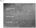
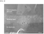
- the cross-section of the thus-prepared thermoelectric module was analyzed by SEM, and the analysis image thereof is shown in FIG. 2 .
- thermoelectric module was prepared in the same manner as in Example 1, except that 26.6 % by weight of Ni powder (3 ⁇ m), 62.1 % by weight of Sn powder (1 ⁇ m), 1.5 % by weight of ethyl cellulose (binder resin), and 9.8 % by weight of dihydro terpineol were mixed to prepare a metal paste.
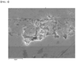
- thermoelectric module The cross-section of the thus-prepared thermoelectric module was analyzed by SEM, and the analysis image thereof is shown in FIG. 3 .
- the porosity of the bonding layer of Comparative Example 1 was about 24 %, confirming that it showed high porosity.
- thermoelectric module of Comparative Example 1 using EDX (energy-dispersive X-ray spectroscopy) is shown in FIG. 4 .
- EDX energy-dispersive X-ray spectroscopy
- thermoelectric module was prepared in the same manner as in Example 1, except that 26.5 % by weight of Ni powder (3 ⁇ m), 60.0 % by weight of Sn 97.8 Ag 1.9 Cu 0.3 powder (2-7 ⁇ m), 1.5 % by weight of ethyl cellulose (binder resin), and 12 % by weight of dihydro terpineol were mixed to prepare a metal paste.
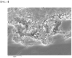
- thermoelectric module The cross-section of the thus-prepared thermoelectric module was analyzed by SEM, and the analysis image thereof is shown in FIG. 5 . Referring to FIG. 5 , it was confirmed that the bonding layer of Comparative Example 2 exhibited high porosity of about 41 %.
- thermoelectric module of Comparative Example 2 the elemental analysis image of the cross-section of the thermoelectric module of Comparative Example 2 using EDX (energy-dispersive X-ray spectroscopy) is shown in FIG. 6 .
- EDX energy-dispersive X-ray spectroscopy
- thermoelectric module was prepared in the same manner as in Example 1, except that 27.4 % by weight of Ni powder (0.3 ⁇ m), 64.6 % by weight of Sn powder (1 ⁇ m), 1.4 % by weight of ethyl cellulose (binder resin), and 6.6 % by weight of dihydro terpineol were mixed to prepare a metal paste.
- thermoelectric module The cross-section of the thus-prepared thermoelectric module was analyzed by SEM, and the analysis image thereof is shown in FIG. 7 .
- the bonding layer of Comparative Example 3 exhibited porosity of about 2.6 %, similar to that of the examples, but it was confirmed through an experimental example described below that the bonding strength and the electrical/thermal properties of the bonding layer were not good compared to the examples not using a binder resin.
- thermoelectric module was prepared in the same manner as in Example 1, except that 73 % by weight of Ag powder (0.3 ⁇ m), 10.0 % by weight of Sn powder (1 ⁇ m), 2.6 % by weight of methyl methacrylate (binder resin), and 14.4 % by weight of isophorone were mixed to prepare a metal paste.
- thermoelectric module A cross-sectional photograph of the thus-prepared thermoelectric module was printed out by using SEM, and the porosity of the bonding layer measured by analyzing particles using an image analysis program (Image J) was about 2.4 %, showing a value similar to those obtained in the examples.
- Image J image analysis program
- thermoelectric module was prepared in the same manner as in Example 1, except that 73 % by weight of Ag powder (0.3 ⁇ m), 10.0 % by weight of Zn powder (6-9 ⁇ m), 2.6 % by weight of methyl methacrylate (binder resin), and 14.4 % by weight of isophorone were mixed to prepare a metal paste.
- thermoelectric module resistivity The bonding layer resistivity, bonding strength, and bonding layer thermal conductivity of the thermoelectric modules prepared in Examples 1 and 2 and Comparative Examples 1 to 5 were measured by the following methods, and the results are shown in Tables 1 and 2 below.
- Bonding strength Instantaneous shear strength when the device ruptures from the electrode by applying a shear force to the thermoelectric device while the thermoelectric device is attached to the substrate through the metal paste was measured using a bond tester (Nordson DAGE 4000).
- Porosity of bonding layer Cross-sectional image of the bonding layer obtained by SEM was measured by analyzing particles using an image analysis program (Image J).
- Resistivity of bonding layer Resistivity value according to temperature was measured by bringing the electrode into contact with the bonding material having a predetermined standard using a resistivity measuring device (Linseis LSR-3).
- Thermal conductivity of bonding layer Thermal diffusivity and thermal conductivity according to temperature were each measured by irradiating the bonding material having a predetermined standard with a laser using a thermal conductivity measuring device (Netzsch LFA457).
- thermoelectric modules prepared in the examples had a high average bonding strength of 22 MPa and 39 MPa, they showed sufficient bonding properties compared to the thermoelectric modules of the comparative examples having a low bonding strength of 12 MPa, 10 MPa, 18 MPa, 11 MPa, and 6 MPa.
- thermoelectric modules prepared in the examples had a low bonding layer resistivity of 61 ⁇ cm, 76 ⁇ cm, and 85 ⁇ cm or less at 50 °C, 300 °C, and 400 °C, respectively, they showed excellent electrical conductivity compared to the thermoelectric modules of the comparative examples having high resistivity.
- thermoelectric modules of the examples had bonding layer thermal conductivity of 12.4 W/m ⁇ k, 16.6 W/m ⁇ k, and 17.2 W/m ⁇ k or higher at 27 °C, 300 °C, and 400 °C, respectively, which were higher thermal conductivities compared to the thermoelectric modules of the comparative examples.
Landscapes
- Engineering & Computer Science (AREA)
- Mechanical Engineering (AREA)
- Chemical & Material Sciences (AREA)
- Inorganic Chemistry (AREA)
- Physics & Mathematics (AREA)
- Dispersion Chemistry (AREA)
- Spectroscopy & Molecular Physics (AREA)
- Manufacturing & Machinery (AREA)
- Powder Metallurgy (AREA)
Claims (12)
- Metallpaste, umfassend: ein erstes Metallpulver, das Nickel (Ni) beinhaltet; ein zweites Metallpulver, das mindestens eines beinhaltet, das aus der Gruppe ausgewählt ist, die aus Zinn (Sn), Zink (Zn), Wismut (Bi) und Indium (In) besteht; und ein Dispergiermittel;dadurch gekennzeichnet, dass das Dispergiermittel Natriumstearat ist; undeine durchschnittliche Partikelgröße des ersten Metallpulvers und des zweiten Metallpulvers unabhängig 10 µm oder weniger beträgt.
- Metallpaste nach Anspruch 1, wobei das erste Metallpulver ferner mindestens eines beinhaltet, das aus der Gruppe ausgewählt ist, die aus Kupfer (Cu), Eisen (Fe) und Silber (Ag) besteht.
- Metallpaste nach Anspruch 1, wobei ein Gewichtsverhältnis zwischen dem ersten Metallpulver und dem zweiten Metallpulver 15:85 bis 90:10 beträgt.
- Metallpaste nach Anspruch 1, wobei das Dispergiermittel in einer Menge von 0,1 Gew.-% bis 5 Gew.-%, bezogen auf das Gesamtgewicht der Paste, enthalten ist.
- Metallpaste nach Anspruch 1, ferner umfassend ein Lösungsmittel mit einem Siedepunkt von 150 °C bis 350 °C.
- Metallpaste nach Anspruch 5, wobei das Lösungsmittel mindestens eines beinhaltet, das aus der Gruppe ausgewählt ist, die aus Alkoholen, Carbonaten, Acetaten und Polyolen besteht.
- Metallpaste nach Anspruch 1, ferner umfassend ein sinterinduzierendes Additiv.
- Metallpaste nach Anspruch 7, wobei das sinterinduzierende Additiv in einer Menge von 2 Gew.-% bis 20 Gew.-%, bezogen auf das Gesamtgewicht der Metallpaste, enthalten ist.
- Thermoelektrisches Modul, umfassend eine Mehrzahl von thermoelektrischen Elementen, umfassend: einen thermoelektrischen Halbleiter; eine Elektrode, die aus einem Metallmaterial besteht und zwischen den thermoelektrischen Elementen verbunden ist; und eine Verbindungsschicht, in der die Metallpaste nach Anspruch 1 gesintert ist, um die thermoelektrischen Elemente und die Elektrode zu verbinden.
- Thermoelektrisches Modul nach Anspruch 9, wobei die Verbindungsschicht eine Porosität von 10 % oder weniger aufweist.
- Thermoelektrisches Modul nach Anspruch 9, wobei die Verbindungsschicht einen spezifischen Widerstand von 70 µΩ·cm oder weniger bei 50 °C und 80 µΩ·cm oder weniger bei 300 °C aufweist.
- Thermoelektrisches Modul nach Anspruch 9, wobei die Verbindungsschicht eine Wärmeleitfähigkeit von 10 W/m·k oder mehr bei 27 °C und 15 W/m·k oder mehr bei 300 °C aufweist.
Applications Claiming Priority (3)
| Application Number | Priority Date | Filing Date | Title |
|---|---|---|---|
| KR20150179577 | 2015-12-15 | ||
| KR1020160127765A KR102101474B1 (ko) | 2015-12-15 | 2016-10-04 | 금속 페이스트 및 열전 모듈 |
| PCT/KR2016/014056 WO2017105011A1 (ko) | 2015-12-15 | 2016-12-01 | 금속 페이스트 및 열전 모듈 |
Publications (3)
| Publication Number | Publication Date |
|---|---|
| EP3349262A1 EP3349262A1 (de) | 2018-07-18 |
| EP3349262A4 EP3349262A4 (de) | 2018-10-31 |
| EP3349262B1 true EP3349262B1 (de) | 2024-02-07 |
Family
ID=59283400
Family Applications (1)
| Application Number | Title | Priority Date | Filing Date |
|---|---|---|---|
| EP16875953.8A Active EP3349262B1 (de) | 2015-12-15 | 2016-12-01 | Metallpaste und thermoelektrisches modul |
Country Status (4)
| Country | Link |
|---|---|
| US (2) | US10622533B2 (de) |
| EP (1) | EP3349262B1 (de) |
| KR (1) | KR102101474B1 (de) |
| CN (1) | CN108140710A (de) |
Families Citing this family (6)
| Publication number | Priority date | Publication date | Assignee | Title |
|---|---|---|---|---|
| KR102474624B1 (ko) * | 2018-05-03 | 2022-12-05 | 주식회사 엘지화학 | 니켈 소결 페이스트 및 이를 이용한 열전 모듈 |
| US11581239B2 (en) | 2019-01-18 | 2023-02-14 | Indium Corporation | Lead-free solder paste as thermal interface material |
| KR102632573B1 (ko) * | 2019-06-07 | 2024-01-31 | 주식회사 엘지화학 | 열전 모듈 제조용 금속 페이스트 및 이를 이용하여 제조된 열전 모듈 |
| CN110153592B (zh) * | 2019-06-20 | 2021-12-28 | 常熟理工学院 | 一种In-Ni体系钎料及其制备方法 |
| CN116408568B (zh) * | 2021-12-30 | 2024-09-10 | 比亚迪股份有限公司 | 一种焊膏和组合件 |
| JP2023144806A (ja) * | 2022-03-28 | 2023-10-11 | 住友金属鉱山株式会社 | 評価装置、評価システム、評価方法、及びプログラム |
Citations (1)
| Publication number | Priority date | Publication date | Assignee | Title |
|---|---|---|---|---|
| EP2799164A1 (de) * | 2013-05-03 | 2014-11-05 | Heraeus Materials Technology GmbH & Co. KG | Verbesserte Sinterpaste mit teilweise oxidierten Metallpartikeln |
Family Cites Families (28)
| Publication number | Priority date | Publication date | Assignee | Title |
|---|---|---|---|---|
| JPS5255611A (en) | 1975-10-31 | 1977-05-07 | Matsushita Electric Ind Co Ltd | Magnetic recording and playback apparatus |
| WO2001089757A1 (en) * | 2000-05-24 | 2001-11-29 | Corbin Stephen F | Variable melting point solders and brazes |
| JP3763520B2 (ja) | 2000-12-25 | 2006-04-05 | Tdk株式会社 | はんだ付け用組成物 |
| US6989110B2 (en) * | 2003-06-13 | 2006-01-24 | Murata Manufacturing Co., Ltd. | Electroconductive paste and method of producing the same |
| JP4490206B2 (ja) | 2004-08-11 | 2010-06-23 | ナミックス株式会社 | 金属ペースト |
| JP4584035B2 (ja) * | 2005-05-31 | 2010-11-17 | トヨタ自動車株式会社 | 熱電モジュール |
| US8388724B2 (en) * | 2006-04-26 | 2013-03-05 | Senju Metal Industry Co., Ltd. | Solder paste |
| JP4933217B2 (ja) | 2006-10-26 | 2012-05-16 | タツタ電線株式会社 | 導電性接着剤 |
| JP4678654B2 (ja) | 2007-09-03 | 2011-04-27 | 有限会社ナプラ | 電子デバイス。 |
| JP5611537B2 (ja) | 2009-04-28 | 2014-10-22 | 日立化成株式会社 | 導電性接合材料、それを用いた接合方法、並びにそれによって接合された半導体装置 |
| KR101276147B1 (ko) * | 2009-09-03 | 2013-06-18 | 가부시키가이샤 무라타 세이사쿠쇼 | 솔더 페이스트, 그것을 사용한 접합 방법, 및 접합 구조 |
| JP5733610B2 (ja) | 2010-01-25 | 2015-06-10 | 三菱マテリアル株式会社 | Au−Sn合金はんだペースト、およびこれにより形成されるAu−Sn合金はんだ |
| KR20130061671A (ko) | 2010-03-18 | 2013-06-11 | 후루카와 덴키 고교 가부시키가이샤 | 도전성 페이스트, 및 이 페이스트로부터 얻어지는 도전접속부재 |
| US9636784B2 (en) * | 2010-05-03 | 2017-05-02 | Indium Corporation | Mixed alloy solder paste |
| JP5811314B2 (ja) * | 2010-06-16 | 2015-11-11 | 国立研究開発法人物質・材料研究機構 | 金属ナノ粒子ペースト、並びに金属ナノ粒子ペーストを用いた電子部品接合体、ledモジュール及びプリント配線板の回路形成方法 |
| KR101414107B1 (ko) * | 2010-11-19 | 2014-07-01 | 가부시키가이샤 무라타 세이사쿠쇼 | 도전성 재료, 그것을 이용한 접속 방법, 및 접속 구조 |
| JP5733678B2 (ja) * | 2010-12-24 | 2015-06-10 | 日立化成株式会社 | 熱電変換モジュールおよびその製造方法 |
| WO2013031588A1 (ja) | 2011-09-02 | 2013-03-07 | 三菱マテリアル株式会社 | ハンダ粉末及びこの粉末を用いたハンダ用ペースト |
| CN103187519B (zh) * | 2011-12-30 | 2016-02-03 | 财团法人工业技术研究院 | 热电模块及其制造方法 |
| TWI605620B (zh) * | 2011-12-30 | 2017-11-11 | 財團法人工業技術研究院 | 熱電模組及其製造方法 |
| KR20140050390A (ko) * | 2012-10-19 | 2014-04-29 | 삼성전자주식회사 | 열전모듈, 이를 구비한 열전장치, 및 열전모듈의 제조방법 |
| KR102156373B1 (ko) | 2013-05-10 | 2020-09-16 | 엘지이노텍 주식회사 | 솔더 페이스트 |
| JP6118192B2 (ja) * | 2013-06-21 | 2017-04-19 | Dowaエレクトロニクス株式会社 | 接合材およびそれを用いた接合方法 |
| JP5967316B2 (ja) * | 2013-11-05 | 2016-08-24 | 千住金属工業株式会社 | Cu核ボール、はんだペースト、フォームはんだ及びはんだ継手 |
| JP6281916B2 (ja) * | 2013-12-03 | 2018-02-21 | 国立大学法人広島大学 | はんだ材料および接合構造体 |
| US10232472B2 (en) * | 2014-11-12 | 2019-03-19 | University Of Maryland College Park | Transient liquid phase sinter pastes and application and processing methods relating thereto |
| CN104741821B (zh) | 2015-04-17 | 2016-10-05 | 哈尔滨工业大学 | 一种用于电子模块高温封装微纳米铜颗粒填充Sn基焊膏的制备方法 |
| CN107251246B (zh) | 2015-07-21 | 2020-05-08 | 株式会社Lg化学 | 热电模块及其制造方法 |
-
2016
- 2016-10-04 KR KR1020160127765A patent/KR102101474B1/ko active Active
- 2016-12-01 US US15/766,167 patent/US10622533B2/en active Active
- 2016-12-01 EP EP16875953.8A patent/EP3349262B1/de active Active
- 2016-12-01 CN CN201680060308.2A patent/CN108140710A/zh active Pending
-
2020
- 2020-03-06 US US16/811,359 patent/US10998482B2/en active Active
Patent Citations (1)
| Publication number | Priority date | Publication date | Assignee | Title |
|---|---|---|---|---|
| EP2799164A1 (de) * | 2013-05-03 | 2014-11-05 | Heraeus Materials Technology GmbH & Co. KG | Verbesserte Sinterpaste mit teilweise oxidierten Metallpartikeln |
Also Published As
| Publication number | Publication date |
|---|---|
| US20200212280A1 (en) | 2020-07-02 |
| EP3349262A1 (de) | 2018-07-18 |
| US20180287032A1 (en) | 2018-10-04 |
| US10998482B2 (en) | 2021-05-04 |
| KR20170071405A (ko) | 2017-06-23 |
| EP3349262A4 (de) | 2018-10-31 |
| KR102101474B1 (ko) | 2020-04-16 |
| US10622533B2 (en) | 2020-04-14 |
| CN108140710A (zh) | 2018-06-08 |
Similar Documents
| Publication | Publication Date | Title |
|---|---|---|
| US10998482B2 (en) | Metal paste and thermoelectric module | |
| EP3590909B1 (de) | Isolierte leiterplatte mit kupfer-keramik-fügekörper, verfahren zur herstellung eines kupfer-keramik-fügekörpers und verfahren zur herstellung einer isolierten leiterplatte | |
| US10016956B2 (en) | Cu/ceramic bonded body, method for manufacturing Cu/ceramic bonded body, and power module substrate | |
| EP3352233B1 (de) | Modul zur thermoelektrischen umwandlung und vorrichtung zur thermoelektrischen umwandlung | |
| EP3041042B1 (de) | Verfahren zur herstellung eines verbundkörpers und verfahren zur herstellung eines strommodulsubstrats | |
| KR20170012119A (ko) | 열전 모듈 및 그 제조 방법 | |
| EP3415578B1 (de) | Elektrisch leitfähiger klebefilm und vereinzelnde chip-bonding-film damit | |
| JP2013258414A (ja) | 熱電モジュール | |
| US9960335B2 (en) | Thermoelectric element, thermoelectric module and method of manufacturing thermoelectric element | |
| KR102063774B1 (ko) | 금속 페이스트 및 열전 모듈 | |
| EP3139419A1 (de) | Modul zur thermoelektrischen umwandlung und herstellungsverfahren dafür | |
| EP3226314B1 (de) | Modul zur thermoelektrischen umwandlung mit spannungsabbaustruktur | |
| JP7315377B2 (ja) | 熱電モジュール | |
| US20160121431A1 (en) | Silver-composite sintering pastes for low-temperature sintering-bonding | |
| CN110402180A (zh) | 接合用成型体及其制造方法 | |
| KR102129050B1 (ko) | 열전 모듈 | |
| JP2007136503A (ja) | 接合用クラッドはんだ | |
| KR102123040B1 (ko) | 열전 모듈 | |
| KR102121438B1 (ko) | 소결 접합층을 포함하는 열전 모듈 | |
| KR102634932B1 (ko) | 전도성 페이스트 | |
| KR102121439B1 (ko) | 금속 페이스트 및 열전 모듈 | |
| KR102632573B1 (ko) | 열전 모듈 제조용 금속 페이스트 및 이를 이용하여 제조된 열전 모듈 | |
| KR102134378B1 (ko) | 열전 모듈 및 그 제조 방법 | |
| WO2017105011A1 (ko) | 금속 페이스트 및 열전 모듈 | |
| TW201623638A (zh) | 基於銀奈米粒子之複合太陽能金屬化漿料 |
Legal Events
| Date | Code | Title | Description |
|---|---|---|---|
| STAA | Information on the status of an ep patent application or granted ep patent |
Free format text: STATUS: THE INTERNATIONAL PUBLICATION HAS BEEN MADE |
|
| PUAI | Public reference made under article 153(3) epc to a published international application that has entered the european phase |
Free format text: ORIGINAL CODE: 0009012 |
|
| STAA | Information on the status of an ep patent application or granted ep patent |
Free format text: STATUS: REQUEST FOR EXAMINATION WAS MADE |
|
| 17P | Request for examination filed |
Effective date: 20180413 |
|
| AK | Designated contracting states |
Kind code of ref document: A1 Designated state(s): AL AT BE BG CH CY CZ DE DK EE ES FI FR GB GR HR HU IE IS IT LI LT LU LV MC MK MT NL NO PL PT RO RS SE SI SK SM TR |
|
| AX | Request for extension of the european patent |
Extension state: BA ME |
|
| A4 | Supplementary search report drawn up and despatched |
Effective date: 20181002 |
|
| RIC1 | Information provided on ipc code assigned before grant |
Ipc: B23K 35/02 20060101ALI20180926BHEP Ipc: B23K 35/36 20060101ALI20180926BHEP Ipc: H01B 1/22 20060101AFI20180926BHEP Ipc: B23K 35/30 20060101ALI20180926BHEP Ipc: H01L 35/08 20060101ALI20180926BHEP Ipc: B23K 35/28 20060101ALI20180926BHEP Ipc: B23K 35/26 20060101ALI20180926BHEP |
|
| DAV | Request for validation of the european patent (deleted) | ||
| DAX | Request for extension of the european patent (deleted) | ||
| STAA | Information on the status of an ep patent application or granted ep patent |
Free format text: STATUS: EXAMINATION IS IN PROGRESS |
|
| 17Q | First examination report despatched |
Effective date: 20191112 |
|
| REG | Reference to a national code |
Ref legal event code: R079 Ipc: H01B0001220000 Ref country code: DE Ref legal event code: R079 Ref document number: 602016085706 Country of ref document: DE Free format text: PREVIOUS MAIN CLASS: H01L0035120000 Ipc: H01B0001220000 |
|
| RIC1 | Information provided on ipc code assigned before grant |
Ipc: H10N 10/817 20230101ALI20231003BHEP Ipc: B23K 35/02 20060101ALI20231003BHEP Ipc: B23K 35/36 20060101ALI20231003BHEP Ipc: B23K 35/30 20060101ALI20231003BHEP Ipc: B23K 35/28 20060101ALI20231003BHEP Ipc: B23K 35/26 20060101ALI20231003BHEP Ipc: H01B 1/22 20060101AFI20231003BHEP |
|
| GRAP | Despatch of communication of intention to grant a patent |
Free format text: ORIGINAL CODE: EPIDOSNIGR1 |
|
| STAA | Information on the status of an ep patent application or granted ep patent |
Free format text: STATUS: GRANT OF PATENT IS INTENDED |
|
| INTG | Intention to grant announced |
Effective date: 20231110 |
|
| GRAS | Grant fee paid |
Free format text: ORIGINAL CODE: EPIDOSNIGR3 |
|
| GRAA | (expected) grant |
Free format text: ORIGINAL CODE: 0009210 |
|
| STAA | Information on the status of an ep patent application or granted ep patent |
Free format text: STATUS: THE PATENT HAS BEEN GRANTED |
|
| AK | Designated contracting states |
Kind code of ref document: B1 Designated state(s): AL AT BE BG CH CY CZ DE DK EE ES FI FR GB GR HR HU IE IS IT LI LT LU LV MC MK MT NL NO PL PT RO RS SE SI SK SM TR |
|
| REG | Reference to a national code |
Ref country code: GB Ref legal event code: FG4D |
|
| REG | Reference to a national code |
Ref country code: CH Ref legal event code: EP |
|
| REG | Reference to a national code |
Ref country code: DE Ref legal event code: R096 Ref document number: 602016085706 Country of ref document: DE |
|
| REG | Reference to a national code |
Ref country code: IE Ref legal event code: FG4D |
|
| REG | Reference to a national code |
Ref country code: LT Ref legal event code: MG9D |
|
| REG | Reference to a national code |
Ref country code: NL Ref legal event code: MP Effective date: 20240207 |
|
| PG25 | Lapsed in a contracting state [announced via postgrant information from national office to epo] |
Ref country code: IS Free format text: LAPSE BECAUSE OF FAILURE TO SUBMIT A TRANSLATION OF THE DESCRIPTION OR TO PAY THE FEE WITHIN THE PRESCRIBED TIME-LIMIT Effective date: 20240607 |
|
| PG25 | Lapsed in a contracting state [announced via postgrant information from national office to epo] |
Ref country code: LT Free format text: LAPSE BECAUSE OF FAILURE TO SUBMIT A TRANSLATION OF THE DESCRIPTION OR TO PAY THE FEE WITHIN THE PRESCRIBED TIME-LIMIT Effective date: 20240207 |
|
| PG25 | Lapsed in a contracting state [announced via postgrant information from national office to epo] |
Ref country code: GR Free format text: LAPSE BECAUSE OF FAILURE TO SUBMIT A TRANSLATION OF THE DESCRIPTION OR TO PAY THE FEE WITHIN THE PRESCRIBED TIME-LIMIT Effective date: 20240508 |
|
| REG | Reference to a national code |
Ref country code: AT Ref legal event code: MK05 Ref document number: 1655892 Country of ref document: AT Kind code of ref document: T Effective date: 20240207 |
|
| PG25 | Lapsed in a contracting state [announced via postgrant information from national office to epo] |
Ref country code: NL Free format text: LAPSE BECAUSE OF FAILURE TO SUBMIT A TRANSLATION OF THE DESCRIPTION OR TO PAY THE FEE WITHIN THE PRESCRIBED TIME-LIMIT Effective date: 20240207 Ref country code: RS Free format text: LAPSE BECAUSE OF FAILURE TO SUBMIT A TRANSLATION OF THE DESCRIPTION OR TO PAY THE FEE WITHIN THE PRESCRIBED TIME-LIMIT Effective date: 20240507 Ref country code: HR Free format text: LAPSE BECAUSE OF FAILURE TO SUBMIT A TRANSLATION OF THE DESCRIPTION OR TO PAY THE FEE WITHIN THE PRESCRIBED TIME-LIMIT Effective date: 20240207 |
|
| PG25 | Lapsed in a contracting state [announced via postgrant information from national office to epo] |
Ref country code: ES Free format text: LAPSE BECAUSE OF FAILURE TO SUBMIT A TRANSLATION OF THE DESCRIPTION OR TO PAY THE FEE WITHIN THE PRESCRIBED TIME-LIMIT Effective date: 20240207 |
|
| PG25 | Lapsed in a contracting state [announced via postgrant information from national office to epo] |
Ref country code: AT Free format text: LAPSE BECAUSE OF FAILURE TO SUBMIT A TRANSLATION OF THE DESCRIPTION OR TO PAY THE FEE WITHIN THE PRESCRIBED TIME-LIMIT Effective date: 20240207 |
|
| PG25 | Lapsed in a contracting state [announced via postgrant information from national office to epo] |
Ref country code: RS Free format text: LAPSE BECAUSE OF FAILURE TO SUBMIT A TRANSLATION OF THE DESCRIPTION OR TO PAY THE FEE WITHIN THE PRESCRIBED TIME-LIMIT Effective date: 20240507 Ref country code: NO Free format text: LAPSE BECAUSE OF FAILURE TO SUBMIT A TRANSLATION OF THE DESCRIPTION OR TO PAY THE FEE WITHIN THE PRESCRIBED TIME-LIMIT Effective date: 20240507 Ref country code: NL Free format text: LAPSE BECAUSE OF FAILURE TO SUBMIT A TRANSLATION OF THE DESCRIPTION OR TO PAY THE FEE WITHIN THE PRESCRIBED TIME-LIMIT Effective date: 20240207 Ref country code: LT Free format text: LAPSE BECAUSE OF FAILURE TO SUBMIT A TRANSLATION OF THE DESCRIPTION OR TO PAY THE FEE WITHIN THE PRESCRIBED TIME-LIMIT Effective date: 20240207 Ref country code: IS Free format text: LAPSE BECAUSE OF FAILURE TO SUBMIT A TRANSLATION OF THE DESCRIPTION OR TO PAY THE FEE WITHIN THE PRESCRIBED TIME-LIMIT Effective date: 20240607 Ref country code: HR Free format text: LAPSE BECAUSE OF FAILURE TO SUBMIT A TRANSLATION OF THE DESCRIPTION OR TO PAY THE FEE WITHIN THE PRESCRIBED TIME-LIMIT Effective date: 20240207 Ref country code: GR Free format text: LAPSE BECAUSE OF FAILURE TO SUBMIT A TRANSLATION OF THE DESCRIPTION OR TO PAY THE FEE WITHIN THE PRESCRIBED TIME-LIMIT Effective date: 20240508 Ref country code: FI Free format text: LAPSE BECAUSE OF FAILURE TO SUBMIT A TRANSLATION OF THE DESCRIPTION OR TO PAY THE FEE WITHIN THE PRESCRIBED TIME-LIMIT Effective date: 20240207 Ref country code: ES Free format text: LAPSE BECAUSE OF FAILURE TO SUBMIT A TRANSLATION OF THE DESCRIPTION OR TO PAY THE FEE WITHIN THE PRESCRIBED TIME-LIMIT Effective date: 20240207 Ref country code: BG Free format text: LAPSE BECAUSE OF FAILURE TO SUBMIT A TRANSLATION OF THE DESCRIPTION OR TO PAY THE FEE WITHIN THE PRESCRIBED TIME-LIMIT Effective date: 20240207 Ref country code: AT Free format text: LAPSE BECAUSE OF FAILURE TO SUBMIT A TRANSLATION OF THE DESCRIPTION OR TO PAY THE FEE WITHIN THE PRESCRIBED TIME-LIMIT Effective date: 20240207 |
|
| PG25 | Lapsed in a contracting state [announced via postgrant information from national office to epo] |
Ref country code: PL Free format text: LAPSE BECAUSE OF FAILURE TO SUBMIT A TRANSLATION OF THE DESCRIPTION OR TO PAY THE FEE WITHIN THE PRESCRIBED TIME-LIMIT Effective date: 20240207 Ref country code: PT Free format text: LAPSE BECAUSE OF FAILURE TO SUBMIT A TRANSLATION OF THE DESCRIPTION OR TO PAY THE FEE WITHIN THE PRESCRIBED TIME-LIMIT Effective date: 20240607 |
|
| PG25 | Lapsed in a contracting state [announced via postgrant information from national office to epo] |
Ref country code: SE Free format text: LAPSE BECAUSE OF FAILURE TO SUBMIT A TRANSLATION OF THE DESCRIPTION OR TO PAY THE FEE WITHIN THE PRESCRIBED TIME-LIMIT Effective date: 20240207 Ref country code: PT Free format text: LAPSE BECAUSE OF FAILURE TO SUBMIT A TRANSLATION OF THE DESCRIPTION OR TO PAY THE FEE WITHIN THE PRESCRIBED TIME-LIMIT Effective date: 20240607 Ref country code: PL Free format text: LAPSE BECAUSE OF FAILURE TO SUBMIT A TRANSLATION OF THE DESCRIPTION OR TO PAY THE FEE WITHIN THE PRESCRIBED TIME-LIMIT Effective date: 20240207 Ref country code: LV Free format text: LAPSE BECAUSE OF FAILURE TO SUBMIT A TRANSLATION OF THE DESCRIPTION OR TO PAY THE FEE WITHIN THE PRESCRIBED TIME-LIMIT Effective date: 20240207 |
|
| PG25 | Lapsed in a contracting state [announced via postgrant information from national office to epo] |
Ref country code: DK Free format text: LAPSE BECAUSE OF FAILURE TO SUBMIT A TRANSLATION OF THE DESCRIPTION OR TO PAY THE FEE WITHIN THE PRESCRIBED TIME-LIMIT Effective date: 20240207 |
|
| PG25 | Lapsed in a contracting state [announced via postgrant information from national office to epo] |
Ref country code: SM Free format text: LAPSE BECAUSE OF FAILURE TO SUBMIT A TRANSLATION OF THE DESCRIPTION OR TO PAY THE FEE WITHIN THE PRESCRIBED TIME-LIMIT Effective date: 20240207 |
|
| PG25 | Lapsed in a contracting state [announced via postgrant information from national office to epo] |
Ref country code: CZ Free format text: LAPSE BECAUSE OF FAILURE TO SUBMIT A TRANSLATION OF THE DESCRIPTION OR TO PAY THE FEE WITHIN THE PRESCRIBED TIME-LIMIT Effective date: 20240207 Ref country code: EE Free format text: LAPSE BECAUSE OF FAILURE TO SUBMIT A TRANSLATION OF THE DESCRIPTION OR TO PAY THE FEE WITHIN THE PRESCRIBED TIME-LIMIT Effective date: 20240207 |
|
| PG25 | Lapsed in a contracting state [announced via postgrant information from national office to epo] |
Ref country code: SK Free format text: LAPSE BECAUSE OF FAILURE TO SUBMIT A TRANSLATION OF THE DESCRIPTION OR TO PAY THE FEE WITHIN THE PRESCRIBED TIME-LIMIT Effective date: 20240207 |
|
| PG25 | Lapsed in a contracting state [announced via postgrant information from national office to epo] |
Ref country code: SM Free format text: LAPSE BECAUSE OF FAILURE TO SUBMIT A TRANSLATION OF THE DESCRIPTION OR TO PAY THE FEE WITHIN THE PRESCRIBED TIME-LIMIT Effective date: 20240207 Ref country code: SK Free format text: LAPSE BECAUSE OF FAILURE TO SUBMIT A TRANSLATION OF THE DESCRIPTION OR TO PAY THE FEE WITHIN THE PRESCRIBED TIME-LIMIT Effective date: 20240207 Ref country code: RO Free format text: LAPSE BECAUSE OF FAILURE TO SUBMIT A TRANSLATION OF THE DESCRIPTION OR TO PAY THE FEE WITHIN THE PRESCRIBED TIME-LIMIT Effective date: 20240207 Ref country code: EE Free format text: LAPSE BECAUSE OF FAILURE TO SUBMIT A TRANSLATION OF THE DESCRIPTION OR TO PAY THE FEE WITHIN THE PRESCRIBED TIME-LIMIT Effective date: 20240207 Ref country code: DK Free format text: LAPSE BECAUSE OF FAILURE TO SUBMIT A TRANSLATION OF THE DESCRIPTION OR TO PAY THE FEE WITHIN THE PRESCRIBED TIME-LIMIT Effective date: 20240207 Ref country code: CZ Free format text: LAPSE BECAUSE OF FAILURE TO SUBMIT A TRANSLATION OF THE DESCRIPTION OR TO PAY THE FEE WITHIN THE PRESCRIBED TIME-LIMIT Effective date: 20240207 |
|
| REG | Reference to a national code |
Ref country code: DE Ref legal event code: R097 Ref document number: 602016085706 Country of ref document: DE |
|
| PG25 | Lapsed in a contracting state [announced via postgrant information from national office to epo] |
Ref country code: IT Free format text: LAPSE BECAUSE OF FAILURE TO SUBMIT A TRANSLATION OF THE DESCRIPTION OR TO PAY THE FEE WITHIN THE PRESCRIBED TIME-LIMIT Effective date: 20240207 |
|
| PLBE | No opposition filed within time limit |
Free format text: ORIGINAL CODE: 0009261 |
|
| STAA | Information on the status of an ep patent application or granted ep patent |
Free format text: STATUS: NO OPPOSITION FILED WITHIN TIME LIMIT |
|
| PG25 | Lapsed in a contracting state [announced via postgrant information from national office to epo] |
Ref country code: IT Free format text: LAPSE BECAUSE OF FAILURE TO SUBMIT A TRANSLATION OF THE DESCRIPTION OR TO PAY THE FEE WITHIN THE PRESCRIBED TIME-LIMIT Effective date: 20240207 |
|
| 26N | No opposition filed |
Effective date: 20241108 |
|
| PG25 | Lapsed in a contracting state [announced via postgrant information from national office to epo] |
Ref country code: SI Free format text: LAPSE BECAUSE OF FAILURE TO SUBMIT A TRANSLATION OF THE DESCRIPTION OR TO PAY THE FEE WITHIN THE PRESCRIBED TIME-LIMIT Effective date: 20240207 |
|
| PG25 | Lapsed in a contracting state [announced via postgrant information from national office to epo] |
Ref country code: MC Free format text: LAPSE BECAUSE OF FAILURE TO SUBMIT A TRANSLATION OF THE DESCRIPTION OR TO PAY THE FEE WITHIN THE PRESCRIBED TIME-LIMIT Effective date: 20240207 |
|
| REG | Reference to a national code |
Ref country code: CH Ref legal event code: PL |
|
| PG25 | Lapsed in a contracting state [announced via postgrant information from national office to epo] |
Ref country code: LU Free format text: LAPSE BECAUSE OF NON-PAYMENT OF DUE FEES Effective date: 20241201 |
|
| REG | Reference to a national code |
Ref country code: BE Ref legal event code: MM Effective date: 20241231 |
|
| PG25 | Lapsed in a contracting state [announced via postgrant information from national office to epo] |
Ref country code: BE Free format text: LAPSE BECAUSE OF NON-PAYMENT OF DUE FEES Effective date: 20241231 |
|
| PG25 | Lapsed in a contracting state [announced via postgrant information from national office to epo] |
Ref country code: CH Free format text: LAPSE BECAUSE OF NON-PAYMENT OF DUE FEES Effective date: 20241231 |
|
| PG25 | Lapsed in a contracting state [announced via postgrant information from national office to epo] |
Ref country code: IE Free format text: LAPSE BECAUSE OF NON-PAYMENT OF DUE FEES Effective date: 20241201 |
|
| PGFP | Annual fee paid to national office [announced via postgrant information from national office to epo] |
Ref country code: DE Payment date: 20251120 Year of fee payment: 10 |
|
| PGFP | Annual fee paid to national office [announced via postgrant information from national office to epo] |
Ref country code: GB Payment date: 20251120 Year of fee payment: 10 |
|
| PGFP | Annual fee paid to national office [announced via postgrant information from national office to epo] |
Ref country code: FR Payment date: 20251125 Year of fee payment: 10 |
|
| PG25 | Lapsed in a contracting state [announced via postgrant information from national office to epo] |
Ref country code: CY Free format text: LAPSE BECAUSE OF FAILURE TO SUBMIT A TRANSLATION OF THE DESCRIPTION OR TO PAY THE FEE WITHIN THE PRESCRIBED TIME-LIMIT; INVALID AB INITIO Effective date: 20161201 |