EP3347181B1 - Dachstein mit angeformter wassersperre - Google Patents
Dachstein mit angeformter wassersperre Download PDFInfo
- Publication number
- EP3347181B1 EP3347181B1 EP16748115.9A EP16748115A EP3347181B1 EP 3347181 B1 EP3347181 B1 EP 3347181B1 EP 16748115 A EP16748115 A EP 16748115A EP 3347181 B1 EP3347181 B1 EP 3347181B1
- Authority
- EP
- European Patent Office
- Prior art keywords
- water barrier
- roof tile
- roof
- tile blank
- blank
- Prior art date
- Legal status (The legal status is an assumption and is not a legal conclusion. Google has not performed a legal analysis and makes no representation as to the accuracy of the status listed.)
- Active
Links
Images

Classifications
-
- B—PERFORMING OPERATIONS; TRANSPORTING
- B28—WORKING CEMENT, CLAY, OR STONE
- B28B—SHAPING CLAY OR OTHER CERAMIC COMPOSITIONS; SHAPING SLAG; SHAPING MIXTURES CONTAINING CEMENTITIOUS MATERIAL, e.g. PLASTER
- B28B11/00—Apparatus or processes for treating or working the shaped or preshaped articles
- B28B11/003—Apparatus or processes for treating or working the shaped or preshaped articles the shaping of preshaped articles, e.g. by bending
-
- B—PERFORMING OPERATIONS; TRANSPORTING
- B29—WORKING OF PLASTICS; WORKING OF SUBSTANCES IN A PLASTIC STATE IN GENERAL
- B29C—SHAPING OR JOINING OF PLASTICS; SHAPING OF MATERIAL IN A PLASTIC STATE, NOT OTHERWISE PROVIDED FOR; AFTER-TREATMENT OF THE SHAPED PRODUCTS, e.g. REPAIRING
- B29C53/00—Shaping by bending, folding, twisting, straightening or flattening; Apparatus therefor
- B29C53/02—Bending or folding
-
- E—FIXED CONSTRUCTIONS
- E04—BUILDING
- E04D—ROOF COVERINGS; SKY-LIGHTS; GUTTERS; ROOF-WORKING TOOLS
- E04D1/00—Roof covering by making use of tiles, slates, shingles, or other small roofing elements
- E04D1/02—Grooved or vaulted roofing elements
- E04D1/04—Grooved or vaulted roofing elements of ceramics, glass or concrete, with or without reinforcement
Definitions
- the invention relates to a roof tile with a molded water barrier according to claim 1.
- Roof tiles with a water barrier are particularly suitable for use on roofs with a low pitch.
- Laying conventional roofing tiles on roofs with a slight pitch of less than 22° is problematic, since the amount of overlapping of the roofing tiles depends on the roof pitch.
- An overlap of the roofing tiles laid from the eaves to the ridge is necessary to prevent water from penetrating, for example in the form of driving rain.
- the strength of the overlap correlates with the pitch of the roof. If the slope is steep, a small overlap is possible, whereas if the slope is small, a strong overlap of roofing tiles without a water barrier is required.
- the roof batten construction must be adjusted according to the overlap. This, as well as the high demand for roofing tiles with large overlaps, significantly increase the material and labor costs.
- the roof construction with heavily overlapping roof tiles already has a high dead weight, which means that further structural measures must be taken into account. This problem of strong overlapping with a low roof pitch is overcome with the help of water barriers.
- the water barrier is then attached to the roof tile blank, which is often used as a separate component.
- the water barrier can be made of the same material as the roof stone, which can be used, for example, in DE 000 00 18 12 456 A1 is shown or made of a material different from the Dachstein, as shown in DE 10 2005 050 657 B3 the case is.
- the water barriers are each pressed as a separate component into the still fresh concrete of the Dachstein. The stability required for the function of the water barrier is obtained after the fresh concrete has dried.
- the disadvantage here is that the roof tile and water barrier have to be manufactured individually and can only be brought together in a further work step.
- the connection between the two parts has weak points. Leaks can occur between the two components during manufacture, which means that water can get into the connection point or even into the roof. If the water that has penetrated into the gaps freezes, frost cracking can occur and thus damage to the connection, the water barrier and/or the roof tile.
- the different materials used in the second example, the roof stone and the water barrier have inconsistent material properties. When the roof surface heats up, a differential coefficient of thermal expansion leads to tension between the water barrier and the roof tile, which can then result in the connection breaking.
- these roof tiles have a heterogeneous visual appearance. Even with a subsequent surface coating, the color of the water barrier may differ from that of the rest of the Dachstein, as the materials have different surface properties.
- the water barrier is formed from the material of the roof tile blank, with a fitting in the watercourses on the Top of the head-side end of the roof tile blank is arranged and a movable forming die penetrates into the rear edge of the roof tile blank and pushes the still fresh concrete up into a mold cavity of the fitting.
- Two different methods are proposed for this. On the one hand, the roof tile blank is lifted and thus brought up to the shaping unit consisting of the shaped piece and shaping die from below. On the other hand, several shaping units are placed on a conveyor belt at a tilted angle onto the roof tile blanks on a conveyor belt. With a constant joint movement of the shaping unit and the roof tile blank, the water barrier is then formed.
- both variants in EP 18 55 856 B1 have the disadvantage that the roof tile blank cannot be precisely aligned with the shaping unit, or vice versa.
- the forming stamp has to be guided at a relatively large distance from the lower edge of the roof tile blank or the upper edge of the lower mold, and a residual portion of concrete, a so-called burr, remains. If the appropriate distance between the punch and the lower mold were not maintained, a collision between the two components would be likely.
- the burr that remains means that not all of the available fresh concrete material is used.
- the small ridge carries the risk of irregularly breaking off, giving the roof tile a poor appearance and perceived by the consumer as damaged. This significantly reduces the quality of the Dachstein.
- JP S57 126614 A , JP S61 56418 U and GB 664 010 A show the production of roofing tiles with a water barrier or at least roofing tiles with a water barrier per se.
- the document EP 18 55 856 B1 discloses a roof tile with a molded water barrier according to the preamble of claim 1.
- the object of the invention is therefore to eliminate the existing disadvantages of the prior art and to provide roofing tiles with a molded water barrier of high quality for use on roofs with a low pitch.
- the production of roofing tiles with a molded water barrier should be inexpensive, economical, reliable and easy to carry out.
- roofing tiles produced using the method should be stackable in order to enable cost-effective transport and to make handling easier for the consumer.
- a method for producing a roof tile with a water stop the water stop being molded onto a roof tile blank which is fed to a lower mold of a shaping unit with a shaped piece and a shaping die that can be moved relative thereto, the shaped piece being placed on a top side of a head-side end of the roof tile blank and the shaping stamp presses against the head end of the roof tile blank, whereby material of the roof tile blank is pressed into a mold cavity of the shaped piece
- the invention provides that the roof tile blank is arranged below the shaping unit and the shaping unit is singed vertically onto the roof tile blank.
- the process control enables the roof tile blank to be precisely aligned under the shaping unit. Since the roof tile blank is stopped below the shaping unit and the shaping does not take place during a movement of the roof tile blank, precise alignment under the shaping unit is possible. The shaping unit is then singed down vertically, which can also be precisely aligned. Furthermore, with this method, a significantly increased production cycle compared to the method according to the prior art, in which the roof tile blank is lifted, reachable. Also, only one shaping unit is required, which reduces the system costs compared to the second variant EP 18 55 856 B1 reduced.
- This exact positioning of the roof tile blank under the shaping unit ensures that the shaping punch is moved parallel to the lower mold and the shaped piece, with an underside of the shaping punch being guided at the same height as the underside of the roof tile blank.
- the tip of the forming stamp can therefore penetrate directly into the parting plane between the upper side of the lower mold and the lower side of the roof tile blank. This is referred to below as the penetration position P of the forming die.
- This penetration position P of the forming die allows a water barrier to be formed in the area of the watercourses without creating a burr.
- the concrete volume that remains in the state of the art is now completely available for the formation of the water barrier, so that a more solid dimensioning of the water barrier and greater compaction of the fresh concrete are achieved.
- the more massive dimensioning reduces a possible risk of fracture and the increased compaction of the concrete reduces the porosity of the water barrier. Reduced porosity means that less water can penetrate and the frost resistance of the roof tile is significantly increased.
- V of fresh concrete For the formation of a high-quality water barrier, it is preferred that a sufficient volume V of fresh concrete is available, so that the highest possible compaction and a sufficiently massive dimensioning of the water barrier can be achieved. This is important because the watertightness of the water barrier increases with the compaction of the fresh concrete and the risk of fracture decreases with an increase in dimensioning. This is ensured by various parameters in favored areas.
- the forming die is pressed into the head end of the roof tile blank with a penetration depth E of 10 to 20 mm.
- the water barrier can be designed with an angle of attack of 60° to 90°.
- the angle of attack ⁇ is preferably approximately 75°.
- This angle of attack ⁇ is determined by the wedge angle ⁇ of the forming die.
- the depth T of the recess of the water barrier is measured from the original head-side edge of the roof tile blank.
- the smallest possible depth T which is determined by the penetration depth E, is important so that the covering length of the roof tiles is not reduced due to an unfavorable positioning of the hanging lugs.
- the hanging lugs are used to attach the roof tiles to the roof batten construction.
- the wedge angle ⁇ of the forming die with an inclination of 60° to 90° is preferred, so that fresh concrete can be pushed on and pressed into the mold cavity of the shaped piece during the movement of the forming die from the head-side edge in the direction of the roof tile blank.
- the wedge effect must be high enough to ensure that the fresh concrete moves upwards and that the cavity is filled and compacted accordingly. With a larger wedge angle (> 90°), the fresh concrete would be pressed downwards, which would result in the underside being compacted.
- the mold cavity would not be filled with fresh concrete that had been pushed on, which would mean that no water barrier would be formed.
- the forming punch With a wedge angle of less than 60°, the forming punch has to carry out a very long feed movement so that a sufficient quantity of fresh concrete is moved into the mold cavity with the small wedge effect. It is not only important that the mold cavity is completely filled, but also that the material is compacted. Due to the large penetration depth of the forming stamp with a small wedge angle, a deep recess would occur, which would mean that the hook-in lugs on the underside of the roofing tile would have to be arranged very far away from the original top edge of the roofing tile. The greater this distance M between the hanging lugs, the shorter the covering length of the roof tile when hanging on the roof battens.
- the water barrier In the area of the Dachstein watercourse, the water barrier must have a sufficient height H between the surface of the watercourse and the top of the water barrier.
- the water barrier should have a height H of at least 5 mm so that wind-induced rainwater can be safely prevented from driving into the overlapping area. If the height H is lower, there is a risk of the water barrier being flooded, which would cause water to penetrate into the roof structure.
- the height of the water stop on the top of a roofing tile lying in the stack may correspond to a maximum projection height of the hanging lugs on the underside of the roofing tile lying above in the stack.
- the roofing tiles can no longer be stacked straight, since the upper roofing tile is then no longer supported by the hanging lug as usual, but by the excessively high water barrier of the roofing tile below.
- the roof stone stack would become crooked and tip over.
- the level of the water barrier is determined during the manufacturing process via the Shape of the mold cavity determined. This results preferably in the mold cavity forming the water barrier with a height of 5 to 20 mm.
- the mold recess forms the water barrier with a thickness S of 5 to 15 mm.
- a thickness S of 5 to 15 mm.
- its root which extends from the top of the roof tile, must have a thickness S of at least 5 mm. If the strength S is lower, not only does the stability suffer, but also the watertightness of the water barrier. However, the thickness S should not be more than 15 mm, as this would have a negative effect on the positioning of the hanging lugs and thus the covering length of the roof tiles.
- the upper side of the roof tile blank is provided with a separating agent before the water barrier is formed.
- a separating agent prevents fresh concrete from adhering and thus prevents a build-up of layers in the mold cavity of the fitting.
- An improved molding accuracy of the water barrier, even over a long period of time during production, can thus be guaranteed.
- sand can be used as a release agent, which is inert and inexpensive. After the shaping process, the sand particles of the loose, dry sand are pressed into the top of the roof tile blank, which means that the visual appearance is not or only minimally affected.
- the release agent is applied as a 2 to 5 cm wide strip to the top of the head end of the roof tile blank.
- This width of applied release agent ensures that there is no build-up of layers in the mold cavity without having to apply release agent to the entire upper side of the roof tile. This saves release agent and continues to achieve the desired effect.
- Other substances as release agents and different application variants are conceivable.
- the unfinished roof tile with a molded water barrier can be subjected to further processing steps.
- the fresh concrete is then dried and hardens.
- a surface coating as well as a color coating to achieve a visual appearance desired by the consumer are also possible.
- the invention relates to a roofing tile with a molded water barrier, which was produced using the method described above, the water barrier and the roofing tile being formed in one piece and the water barrier having a flat rear side. If, according to the invention, the water barrier and the roof tile are designed in one piece, the connection between the two has no weak points that would lead to leaks or weather-related damage. In addition, the level rear allows as much volume of fresh concrete as possible to form the water barrier. This allows enough material to be deformed for massive dimensioning and high density.
- the Dachstein is characterized in that the water barrier has an increased density. This reduces the porosity and thereby reduces the penetration of water. The stability against environmental influences is increased compared to the prior art.
- the Dachstein has preferred shaping parameters analogous to the method.
- the water barrier should have an angle of attack ⁇ of 60° to 90°. In particular, an angle of attack ⁇ of 75° is considered optimal.
- the water stop has a thickness S of 5 to 15 mm, which ensures sufficient stability of the water stop. The penetration of water into the roof truss and good stackability of the roof tiles is ensured by the water barrier having a height of 5 to 20 mm.
- the water barrier is formed from sufficient fresh concrete, which influences the compaction at this point, and at the same time does not negatively affect the cover length when roofing, the water barrier, in the area of the watercourse with a depth T of a recess, to the head end of the roof tile blank, of 10 formed up to 20 mm.
- At least one hook-in lug is formed on the underside of the roofing tile blank at a minimum distance M from the head end of the roofing tile blank.
- the minimum distance M of the at least one hanging lug corresponds to at least the sum of the depth T of the recess and the thickness S of the water barrier (M ⁇ T + S). This ensures that when the roofing tiles are stacked, the water barrier formed on the top of a roofing tile does not collide with the hook-in lugs on the underside of a roofing tile lying above in the stack. If the minimum distance M were smaller than the sum of the depth T and the thickness S, water barrier and Attachment lugs at least partially in the same position. This would cause the roof tile stack to become crooked and could tip over more quickly.
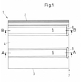
- the Dachstein 1 shows a roof tile 1 according to the invention in plan view.
- the Dachstein 1 has a water fold 2 and a cover fold 3 on its longitudinal edges, as well as a central flange 4 lying between them. Between the folds 2, 3 and the central brim 4, a watercourse 5, 6 is formed.
- a water barrier 8, 9 is formed in each case in the area of the watercourse 5, 6.
- the water barrier 8, 9 extends at least over the area of the watercourse 5, 6.
- a single water barrier can also run over the entire length of the top edge 7 of the Dachstein 1.
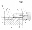
- the water stop 8, 9 is formed at the head end 7 in the area of the watercourse 5 of a roof tile blank 10
- Roof tile blank 10 made of fresh concrete 11 rests with its underside 12 on a lower mold 13 .
- a shaping unit 14 which is formed from a shaped piece 15 with a mold trough 16 and a shaping die 17, this is lowered vertically.
- the lateral opening of the mold cavity 16 is arranged opposite the wedge-shaped mold stamp 17 .
- the shaped piece 15 with the shaped cavity 16 the inner contour of which corresponds to the shape of the water barrier to be produced, lies on an upper side 18 of the roof tile blank 10 near the head-side edge 7.
- the shaped cavity 16 has an L-shaped cross section with rounded corners .
- a separating layer 19 is applied to the upper side 18 of the roof tile blank 10 near the edge 7 on the head side before the shaped piece 15 is placed in place.
- This separating layer 19 can preferably consist of a scattered layer of loose, dry sand particles 20 and prevents the fresh concrete 11 from adhering to the mold cavity 16.
- the fresh concrete 11 for forming the water barrier 8 is obtained by pushing the forming die 17, which is provided with a wedge angle ⁇ , from the head side Penetrates the roof stone blank 10 at the end of 7.
- the forming die 17 is reversingly moved parallel to the lower mold 13, the underside 21 of the forming die 17 being guided at a level with the underside 12 of the roof tile blank.
- the penetration position is denoted by P.
- the fresh concrete 11 detaches itself from the lower mold 13 and slides upwards on the sloping wedge surface into the mold cavity 16, where it is compacted to form the water barrier 8.
- the particles of the separating layer 19, for example sand particles 20 lie against the wall of the mold cavity 16 and thus ensure good detachment of the formed water barrier 8 from the mold cavity 16.
- the sand particles 20 are in the upper side 18 of the roof tile blank 10 or the water barrier 8 pressed, so that they do not appear optically or only minimally.
- the head-side end 7 of the roof tile blank 10 jumps back in the area of the watercourse 5 or the water barrier 8 arranged there compared to a plane E1.
- the plane E1 is formed by the original end 7 on the head side.
- this recess 22 has a depth T that corresponds to the penetration depth E of the forming die 17.
- the wedge angle ⁇ of the forming die 17 is at least 60° and should not exceed 90°.
- the wedge angle ⁇ is preferably approximately 75°.
- the forming die 17 must carry out a very long advance movement so that, given the small wedge effect, an upward movement of the fresh concrete 11 sufficient for filling the forming cavity 16 and for compacting is generated.
- a very deep recess 22 occurs at the head-side end 7 of the roof tile blank 10 due to the necessary large penetration depth E of the forming die 17, as a result of which the hook-in lugs 23 are arranged on the underside 12 of the roof tile blank 10 at a very large distance from the plane E1 of the head-side end 7 would have to.
- a reduction in the covering length has the disadvantage that more rows of roofing tiles running parallel to the eaves have to be laid in the direction of the ridge and eaves. This increases the load on the roof substructure, material and labor costs.
- the wedge angle ⁇ of the forming stamp 17 and the penetration depth E of the forming stamp 17 should therefore be coordinated in such a way that a recess 22 with the smallest possible depth T is created on the roof tile 1, so that on the one hand the covering length of the roof tile 1 is not reduced by an unfavorable positioning of hanging lugs 23 is reduced and on the other hand the largest possible volume V of fresh concrete 11 is obtained.
- it is also important to place the penetration position P of the forming die 17 in the parting plane ( E2) between the underside 12 of the roof tile blank 10 and an upper side 24 of the lower mold 13.
- the forming of the water barrier 8, 9 takes place in four work steps: First, the unfinished roof tile 10 is positioned precisely below the shaping unit 14, with the shaped piece 15 being located near the end 7 of the unfinished roof tile 10 on the head side.
- the shaping unit 14 can be moved reversing vertically in the direction of the upper side 18 of the roof tile blank 10 .
- the shaping unit 14 is lowered in the direction of the upper side 18 of the roof tile blank 10, the shaped piece 15 coming to rest on the upper side 18 of the roof tile blank 10 and the side opening of the mold cavity 16 being arranged at the head end 7.
- the forming die 17 is lowered so that its tip is positioned in front of the lower mold 13 and at the level of the parting plane between the upper side 24 of the lower mold 13 and the lower side 12 of the roof tile blank 10 .
- the forming die 17 executes a movement parallel to the lower mold 13 and directed towards the head end of the roof tile blank 30, during which the forming die 17, which is provided with the wedge angle ⁇ , penetrates the fresh concrete 11 and presses it into the mold cavity 16 of the shaped piece 15 .
- the forming stamp 17 penetrates the penetration depth E into the forming cavity 16 .
- the pressed fresh concrete 11 fills the mold trough 16 completely, so that a roof tile blank 10 with a monolithically formed water barrier 8, 9 is produced.
- the shaping die 17 is then returned to its starting position, and in the fourth work step, the shaping unit 14 is pulled back from the top of the roof tile blank 18, so that the shaped piece 15 is removed from the top of the roof tile blank 10 and the mold cavity 16 monolithically molded on Water locks 8, 9 are free. Further steps connected to the production process can serve for surface coating, curing and packaging.
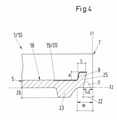
- the roof tile blank 10 or roof tile 1 with a water barrier 8 produced using the method according to the invention is in 4 shown.
- the shaping parameters preferred in the process can be seen on the finished roof tile 1.
- the water stop 5 has an angle of attack ⁇ , based on the plane E2, which corresponds to the wedge angle ⁇ of the forming die 17.
- the depth T of the recess 22 corresponds to Penetration depth E of the forming die 17, which should be at least 10 mm and should not exceed 22 mm.
- the water barrier 8 on the top 18 of a roofing tile 1 at the bottom of the stack should not be positioned in the same place as the hanging lug 23 on the bottom 12 of a roofing tile 1 at the top of the stack, otherwise the stack would the roof tiles 1 become crooked and tilt.
- the hanging lugs 23 should maintain a minimum distance M from the head end 7 of the roof tile 1, which results as follows: M ⁇ depth T of the recess 22 + thickness S of the Root 25 of the water barrier 8, 9.
Landscapes
- Engineering & Computer Science (AREA)
- Chemical & Material Sciences (AREA)
- Ceramic Engineering (AREA)
- Structural Engineering (AREA)
- Mechanical Engineering (AREA)
- Architecture (AREA)
- Civil Engineering (AREA)
- Press-Shaping Or Shaping Using Conveyers (AREA)
Description
- Die Erfindung betrifft einen Dachstein mit angeformter Wassersperre nach Anspruch 1.
- Dachsteine mit Wassersperre sind insbesondere für den Einsatz auf Dächern mit geringer Neigung geeignet. Ein Verlegen von herkömmlichen Dachsteinen auf Dächern mit einer geringen Neigung unter 22° ist problematisch, da das Maß der Überlappung der Dachsteine von der Dachneigung abhängig ist. Eine Überlappung der, von Traufe nach First verlegten, Dachsteine ist notwendig um ein Eindringen von Wasser, in Form von beispielsweise Schlagregen, zu verhindern. Weiterhin korreliert die Stärke der Überlappung mit der Dachneigung. Bei starker Neigung ist eine geringe Überlappung möglich, wohingegen bei geringer Neigung eine starke Überlappung von Dachsteinen ohne Wassersperre erforderlich ist. Dadurch bedingt, muss die Dachlattenkonstruktion entsprechend der Überlappung angepasst werden. Dieses, sowie der hohe Dachsteinbedarf bei starker Überlappung, erhöhen die Material- und Arbeitskosten deutlich. Zusätzlich weist die Dachkonstruktion mit stark überlappenden Dachsteinen bereits ein hohes Eigengewicht auf, wodurch weitere bauliche Maßnahmen beachtet werden müssen. Diese Problematik der starken Überlappung bei geringer Dachneigung wird mit Hilfe von Wassersperren überwunden.
- Es sind verschiedene Verfahren für das Anbringen einer Wassersperre an einen Dachstein bekannt. Dabei wird meist der Dachstein, beziehungsweise der Dachsteinrohling, aus Frischbeton vorgeformt. Mittels Strangpressverfahren wird eine Frischbetonschicht als endloses Band auf aneinander gereihte Unterformen gleicher Länge aufgebracht. Die Oberflächenkontur des Dachsteins wird, bereits in diesen frühen Herstellungsschritten, durch Formwerkzeuge vorgegeben. Der Strang wird anschließend in einer Schneidstation in Untereinheiten zerschnitten, so dass jede Unterform einen einzelnen Dachsteinrohling trägt. Die Herstellung von Dachsteinen aus Beton im Strangpreßverfahren ist in den Dokumenten
DE 3522 846 A1 undDE 22 52 047 C3 beschrieben. - Das Anbringen der Wassersperre an den Dachsteinrohling erfolgt anschließend, wobei diese häufig als separates Bauteil eingesetzt wird. Dabei kann die Wassersperre aus demselben Material wie der Dachstein bestehen, welches beispielsweise in
DE 000 00 18 12 456 A1 gezeigt ist oder aus einem vom Dachstein abweichenden Material, wie es inDE 10 2005 050 657 B3 der Fall ist. Die Wassersperren werden jeweils als separates Bauteil in den noch frischen Beton des Dachsteins eingepresst. Die für die Funktion der Wassersperre notwendige Stabilität wird nach Trocknung des Frischbetons erhalten. - Hierbei nachteilig ist, dass Dachstein und Wassersperre einzeln hergestellt werden müssen und erst in einem weiteren Arbeitsschritt zusammengeführt werden können. Die Verbindung der beiden Teile weist Schwachstellen auf. So können bei der Herstellung Undichtigkeiten zwischen den beiden Bauteilen auftreten, wodurch Wasser in die Verbindungsstelle oder sogar ins Dach eintreten kann. Friert das in die Zwischenräume eingedrungene Wasser, kann es zu Frostsprengungen kommen und somit zur Beschädigungen der Verbindung, der Wassersperre und/oder des Dachsteins. Weiterhin weisen die im zweiten Beispiel verwendeten unterschiedlichen Materialen von Dachstein und Wassersperre uneinheitliche Materialeigenschaften auf. Ein differenzierender Wärmeausdehnungskoeffizient führt, bei Erwärmung der Dachfläche, zu Spannungen zwischen Wassersperre und Dachstein, welches dann einen Bruch der Verbindung zur Folge haben kann. Zusätzlich weisen diese Dachsteine ein heterogenes optisches Erscheinungsbild auf. Auch bei einer anschließenden Oberflächenbeschichtung kann es zu einem abweichenden Farbton der Wassersperre vom restlichen Dachstein kommen, da die Materialien verschiedene Oberflächeneigenschaften besitzen.
- Eine andere Variante der Herstellung eines Dachsteins mit Wassersperre ist in
EP 18 55 856 B1 beschrieben. Gemäß dieser Patentschrift wird die Wassersperre aus dem Material des Dachsteinrohlings ausgebildet, wobei ein Formstück im Bereich der Wasserläufe auf der Oberseite des kopfseitigen Endes des Dachsteinrohlings angeordnet wird und ein bewegbarer Formstempel in die hintere Kante des Dachsteinrohlings eindringt und den noch frischen Beton nach oben in eine Formmulde des Formstücks drückt. Hierfür werden zwei unterschiedliche Verfahren vorgeschlagen. Zum einen wird der Dachsteinrohling angehoben und so von unten an die Formgebungseinheit aus Formstück und Formstempel herangeführt. Zum anderen werden mehrere Formgebungseinheiten auf einem Förderband in gekippten Winkel auf die auf einem Laufband befindlichen Dachsteinrohlinge aufgesetzt. Bei konstanter gemeinsamer Bewegung der Formgebungseinheit und des Dachsteinrohlings erfolgt anschließend die Ausbildung der Wassersperre. - Beide Varianten in
EP 18 55 856 B1 haben den Nachteil, dass keine genaue Ausrichtung des Dachsteinrohlings zu der Formgebungseinheit, oder entsprechend andersherum, erfolgen kann. Dadurch muss der Formstempel in einem relativ großen Abstand zu der Unterkante des Dachsteinrohlings, beziehungsweise der Oberkante der Unterform, geführt werden und ein Restanteil an Beton, ein sogenannter Grat, bleibt stehen. Würde kein entsprechender Abstand von Stempel zu Unterform gewahrt werden, so wäre eine Kollision der beiden Bauteile wahrscheinlich. Der zurückbleibende Grat führt dazu, dass nicht das gesamte, zur Verfügung stehende Frischbetonmaterial ausgenutzt wird. Zusätzlich birgt der schmale Grat die Gefahr, unregelmäßig abzubrechen, wodurch der Dachstein ein mangelhaftes Erscheinungsbild aufweist und vom Verbraucher als beschädigt angesehen wird. Dieses mindert die Qualität des Dachsteins deutlich. Weiterhin hat sich herausgestellt, dass die beschriebenen Verfahren nicht wirtschaftlich genug sind. So beschränkt das Anheben des Dachsteinrohlings in die Bearbeitungsposition im ersten beschriebenen Verfahren den Produktionstakt auf wenige Dachsteine pro Minute. Im zweiten Verfahren ist ein höherer Produktionstakt möglich, allerdings werden hier mehrere Formgebungseinheiten auf einem Förderband benötigt, welches die Maschinenanschaffungskosten erhöht. Zusätzlich ist hierbei problematisch, dass ein hoher Produktionstakt kaum ausreichend Zeit zum Reinigen der einzelnen Formgebungseinheiten zur Verfügung stellt. Eine ungenügende Reinigung führt zu einem Schichtaufbau in der Formmulde und somit zu einer unvollständigen Formung der Wassersperre. Bei ungenügender Höhe der Wassersperre kann Wasser ins Dach eindringen und bei nicht ausreichender Stärke kann die Wassersperre bei mechanischer Beanspruchung abbrechen. Zur Beseitigung des Schichtaufbaus in der Formmulde sind ferner häufige Unterbrechungen der laufenden Produktion notwendig, wodurch der Produktionstakt vermindert und eine erhöhte Personalleistung erforderlich wird. - Auch die Dokumente
JP S57 126614 A JP S61 56418 U GB 664 010 A EP 18 55 856 B1 offenbart einen Dachstein mit angeformter Wassersperre nach dem Oberbegriff des Anspruchs 1. - Aufgabe der Erfindung ist es daher, die bestehenden Nachteile des Stands der Technik zu beseitigen, sowie Dachsteine mit angeformter Wassersperre in hoher Qualität für den Einsatz auf Dächern mit geringer Neigung bereitzustellen. Die Herstellung von Dachsteinen mit angeformter Wassersperre soll dabei kostengünstig, wirtschaftlich, zuverlässig und einfach durchführbar sein.
- Darüber hinaus sollten die mit dem Verfahren hergestellten Dachsteine gut stapelbar sein, um einen kostengünstigen Transport zu ermöglichen und die Handhabung für den Verbraucher zu erleichtern.
- Hauptmerkmale der Erfindung sind im kennzeichnenden Teil des Anspruchs 1 angegeben. Ausgestaltungen sind Gegenstand der Ansprüche 2 bis 5.
- Bei einem Verfahren zur Herstellung eines Dachsteins mit einer Wassersperre, wobei die Wassersperre an einen Dachsteinrohling angeformt wird, der auf einer Unterform einer Formgebungseinheit mit einem Formstück und einem relativ dazu bewegbaren Formstempel zugeführt wird, wobei das Formstück auf eine Oberseite eines kopfseitigen Endes des Dachsteinrohlings aufgelegt wird und der Formstempel gegen das kopfseitige Ende des Dachsteinrohlings drückt, wobei Material des Dachsteinrohlings in eine Formmulde des Formstücks gedrückt wird, sieht die Erfindung vor, dass der Dachsteinrohling unterhalb der Formgebungseinheit angeordnet und die Formgebungseinheit vertikal auf den Dachsteinrohling abgesengt wird.
- Die Verfahrensführung ermöglicht eine exakte Ausrichtung des Dachsteinrohlings unter der Formgebungseinheit. Da der Dachsteinrohling unterhalb der Formgebungseinheit gestoppt wird und die Anformung nicht während einer Bewegung des Dachsteinrohlings erfolgt, ist eine präzise Ausrichtung unter der Formgebungseinheit möglich. Anschließend wird die Formgebungseinheit vertikal abgesengt, welches ebenfalls präzise ausgerichtet möglich ist. Weiterhin ist bei dieser Verfahrensführung ein deutlich erhöhter Produktionstakt, verglichen mit dem Verfahren gemäß dem Stand der Technik, in dem der Dachsteinrohling angehoben wird, erreichbar. Auch wird nur eine Formgebungseinheit benötigt, welches die Anlagenkosten gegenüber der zweiten Variante aus
EP 18 55 856 B1 reduziert. - Durch diese exakte Positionierung des Dachsteinrohlings unter der Formgebungseinheit wird erreicht, dass der Formstempel parallel zu der Unterform und dem Formstück bewegt wird, wobei eine Unterseite des Formstempels auf einer Höhe mit einer Unterseite des Dachsteinrohlings geführt wird. Die Spitze des Formstempels kann also direkt in der Trennebene zwischen der Oberseite der Unterform und der Unterseite des Dachsteinrohlings eindringen. Dieses wird im Folgenden als Eindringposition P des Formstempels bezeichnet. Durch diese Eindringposition kann eine Wassersperre im Bereich der Wasserläufe ausgebildet werden, ohne dass ein Grat entsteht. Das beim Stand der Technik stehen bleibende Betonvolumen steht nun vollständig zur Ausbildung der Wassersperre zur Verfügung, so dass eine massivere Dimensionierung der Wassersperre und eine höhere Verdichtung des Frischbetons erzielt wird. Die massivere Dimensionierung reduziert eine mögliche Bruchgefahr und die erhöhte Verdichtung des Betons reduziert die Porosität der Wassersperre. Durch eine verminderte Porosität kann weniger Wasser eindringen und die Frostbeständigkeit des Dachsteins wird deutlich gesteigert.
- Für die Formung einer qualitativ hochwertigen Wassersperre ist bevorzugt, dass ein ausreichendes Volumen V an Frischbeton zur Verfügung steht, so dass eine möglichst hohe Verdichtung und eine ausreichend massive Dimensionierung der Wassersperre erzielt werden kann. Dieses ist wichtig da die Wassserdichtigkeit der Wassersperre mit der Verdichtung des Frischbetons zunimmt sowie die Bruchgefahr mit einer Zunahme der Dimensionierung abnimmt. Dieses wird durch verschiedene Parameter in favorisierten Bereichen gewährleistet.
- In einer bevorzugten Ausführungsform des Verfahrens wird der Formstempel mit einer Eindringtiefe E von 10 bis 20 mm in das kopfseitige Ende des Dachsteinrohlings gedrückt. Weiterhin kann die Wassersperre mit einem Anstellwinkel von 60° bis 90° ausgebildet werden. Vorzugsweise beträgt der Anstellwinkel β etwa 75°. Dieser Anstellwinkel β wird durch den Keilwinkel α des Formstempels bestimmt. Der Keilwinkel α und die Eindringtiefe E des Formstempels sollten so aufeinander abgestimmt werden, dass am kopfseitigen Dachsteinende ein Rücksprung mit einer möglichst geringen Tiefe T (T = E) entsteht, aber dennoch ein möglichst großes Volumen V an Frischbeton zur Verfügung steht. Die Tiefe T des Rücksprungs der Wassersperre wird vom ursprünglichen kopfseitigen Rand des Dachsteinrohlings her gemessen. Die möglichst geringe Tiefe T, welche über die Eindringtiefe E bestimmt wird, ist wichtig, damit die Eindecklänge der Dachsteine nicht durch eine ungünstige Positionierung der Einhängenasen reduziert wird. Die Einhängenasen dienen der Befestigung der Dachsteine auf der Dachlattenkonstruktion.
- Der Keilwinkel α des Formstempels mit einer Neigung von 60° bis 90° ist bevorzugt, damit bei der Bewegung des Formstempels, vom kopfseitigen Rand her in Richtung des Dachsteinrohlings, Frischbeton aufgeschoben und in die Formmulde des Formstücks gedrückt werden kann. Dabei muss die Keilwirkung hoch genug sein, damit eine ausreichende Aufwärtsbewegung des Frischbetons erzielt wird und die Formmulde entsprechend ausgefüllt und verdichtet wird. Bei einem größeren Keilwinkel (> 90°) würde der Frischbeton nach unten gedrückt werden, wodurch es zu einer Verdichtung der Unterseite kommen würde. Die Formmulde würde nicht mit aufgeschobenen Frischbeton gefüllt werden, wodurch keine Wassersperre ausgebildet werden würde. Bei einem Keilwinkel kleiner 60° muss der Formstempel eine sehr lange Vorschubbewegung ausführen, damit bei der geringen Keilwirkung eine ausreichende Menge Frischbeton in die Formmulde bewegt wird. Dabei ist nicht nur die vollständige Füllung der Formmulde wichtig, sondern auch eine Verdichtung des Materials. Aufgrund der großen Eindringtiefe des Formstempels bei geringem Keilwinkel würde ein tiefer Rücksprung entstehen, wodurch die Einhängenasen an der Unterseite des Dachsteins sehr weit vom ursprünglichen kopfseitigen Rand des Dachsteins entfernt angeordnet werden müssten. Je größer dieser Abstand M der Einhängenasen ist, desto geringer wird die Eindecklänge des Dachsteins beim Einhängen an den Dachlatten.
- Die Wassersperre muss im Bereich des Wasserlaufs des Dachsteins eine ausreichende Höhe H zwischen der Oberfläche des Wasserlaufs und der Oberseite der Wassersperre aufweisen. Damit der windbedingte Eintrieb von Regenwasser im Überlappungsbereich sicher verhindert werden kann, sollte die Wassersperre wenigstens eine Höhe H von 5 mm aufweisen. Wird die Höhe H geringer ausgeführt, besteht die Gefahr der Überflutung der Wassersperre, wodurch Wasser in den Dachstuhl eindringen würde. Um zusätzlich eine Stapelbarkeit der Dachsteine sicherzustellen, darf die Höhe der Wassersperre auf der Oberseite eines im Stapel liegenden Dachsteins, maximal einer Vorsprungshöhe der Einhängenasen auf der Unterseite des im Stapel oberhalb liegenden Dachsteins, entsprechen. Wird die Höhe H der Wassersperre höher angesetzt, lassen sich die Dachsteine nicht mehr gerade stapeln, da der obere Dachstein dann nicht mehr wie üblich über die Einhängenase abgestützt wird, sondern über die zu hohe Wassersperre des unterhalb liegenden Dachsteins. Der Dachsteinstapel würde schief werden und kippen. Die Höhe der Wassersperre wird während des Herstellungsverfahrens über die Form der Formmulde bestimmt. Daraus ergibt sich bevorzugt, dass die Formmulde die Wassersperre mit einer Höhe von 5 bis 20 mm ausbildet.
- In einer alternativen Ausgestaltung des erfindungsgemäßen Verfahrens ist vorgesehen, dass die Formmulde die Wassersperre in einer Stärke S von 5 bis 15 mm formt. Dachsteine werden beim Verlegen meistens am kopfseitigen Ende angefasst und oftmals von Dachdecker zu Dachdecker geworfen, so dass die angeformte Wassersperre hohen mechanischen Belastungen ausgesetzt ist. Um der Wassersperre eine ausreichende Stabilität zu verleihen, wodurch eine Abbruchgefahr der Wassersperre minimiert werden soll, muss deren von der Oberseite des Dachsteins ausgehende Wurzel eine Stärke S von wenigstens 5 mm besitzen. Wird die Stärke S geringer ausgeführt, so leidet nicht nur die Stabilität, sondern auch die Wasserdichtigkeit der Wassersperre. Die Stärke S sollte allerdings auch nicht mehr als 15 mm betragen, denn dies würde die Positionierung der Einhängenasen und dadurch die Eindecklänge der Dachsteine negativ beeinflussen.
- Bei einer bevorzugten Fortbildung des Verfahrens wird die Oberseite des Dachsteinrohlings vor der Ausbildung der Wassersperre mit einem Trennmittel versehen. Dieses verhindert ein Anhaften von Frischbeton und damit einen Schichtaufbau in der Formmulde des Formstücks. Eine verbesserte Anformgenauigkeit der Wassersperre, auch über einen langen Zeitraum während der Produktion, kann somit gewährleistet werden. Beispielweise kann als Trennmittel Sand verwendet werden, welcher inert und kostengünstig ist. Nach dem Formungsvorgang sind die Sandpartikel, des losen, trockenen Sandes, in die Oberseite des Dachsteinrohlings eingedrückt, wodurch das optische Erscheinungsbild nicht oder nur minimal beeinflusst wird. In einer Variante des Verfahrens wird das Trennmittel als 2 bis 5 cm breiter Streifen auf die Oberseite des kopfseitigen Endes des Dachsteinrohlings aufgetragen. Diese Breite an aufgetragenem Trennmittel gewährleistet, dass es zu keinem Schichtaufbau in der Formmulde kommt, ohne dass die gesamte Oberseite des Dachsteins mit Trennmittel versehen werden müsste. Dadurch wird Trennmittel gespart und der gewünschte Effekt weiterhin erzielt. Weitere Substanzen als Trennmittel und verschiedene Auftragevarianten sind denkbar.
- Gemäß einer Ausgestaltung des Verfahrens kann der Dachsteinrohling mit angeformter Wassersperre weiteren Bearbeitungsschritten unterzogen werden. So wird der Frischbeton anschließend getrocknet und härtet aus. Auch eine Oberflächenbeschichtung sowie eine Farbbeschichtung, um ein vom Verbraucher gewünschte optisches Erscheinungsbild zu erzielen, sind möglich.
- Die Erfindung betrifft einen Dachstein mit angeformter Wassersperre, der mit dem vorher beschriebenen Verfahren hergestellt wurde, wobei die Wassersperre und der Dachstein einstückig ausgebildet sind und die Wassersperre eine ebene Rückseite aufweist. Wenn erfindungsgemäß die Wassersperre und der Dachstein einstückig ausgebildet sind, weist die Verbindung der beiden keine Schwachstellen auf, die zu Undichtigkeit oder witterungsbedingten Schäden führen würden. Zusätzlich ermöglicht die ebene Rückseite, dass möglichst viel Volumen an Frischbeton zur Verfügung steht, um die Wassersperre auszubilden. Dadurch kann ausreichend Material für eine massive Dimensionierung und hohe Dichte verformt werden.
- Der Dachstein ist in einer bevorzugten Ausführungsform dadurch gekennzeichnet, dass die Wassersperre eine erhöhte Dichte aufweist. Dieses reduziert die Porosität und vermindert dadurch das Eindringen von Wasser. Die Stabilität gegenüber Umwelteinflüssen wird gegenüber dem Stand der Technik erhöht.
- In favorisierten Ausführungsformen weist der Dachstein analog zu dem Verfahren bevorzugte formgebende Parameter auf. So sollte die Wassersperre einen Anstellwinkel β von 60° bis 90° aufweisen. Im speziellen wird ein Anstellwinkel β von 75° als optimal angesehen. Weiterhin wird vorgezogen, dass die Wassersperre eine Stärke S von 5 bis 15 mm aufweist, wodurch eine ausreichende Stabilität der Wassersperre gewährleistet wird. Das Eindringen von Wasser in den Dachstuhl und eine gute Stapelbarkeit der Dachsteine wird sichergestellt, indem die Wassersperre eine Höhe von 5 bis 20 mm aufweist. Damit die Wassersperre aus ausreichend Frischbeton ausgebildet wird, welches die Verdichtung an dieser Stelle beeinflusst, und zugleich die Decklänge beim Dachdecken nicht negativ beeinflusst, ist die Wassersperre, im Bereich des Wasserlaufs mit einer Tiefe T eines Rücksprungs, zum kopfseitigen Ende des Dachsteinrohlings, von 10 bis 20 mm ausgebildet.
- Es ist vorgesehen, dass mindestens eine Einhängenase an der Unterseite des Dachsteinrohlings in einem Mindestabstand M zum kopfseitigen Ende des Dachsteinrohlings ausgebildet ist. Dabei entspricht der Mindestabstand M der mindestens einen Einhängenase mindestens der Summe aus der Tiefe T des Rücksprungs und der Stärke S der Wassersperre (M ≥ T + S). Dieses stellt sicher, dass beim Stapeln der Dachsteine die angeformte Wassersperre auf der Oberseite eines Dachsteins nicht mit den Einhängenasen auf der Unterseite eines im Stapel oberhalb liegenden Dachsteins kollidiert. Wäre der Mindestabstand M kleiner als die Summe aus der Tiefe T und der Stärke S, wären Wassersperre und Einhängenasen zumindest teilweise auf der gleichen Position. Dies würde dazu führen, dass der Dachsteinstapel schief wird und schneller kippen könnte.
- Weitere Merkmale, Einzelheiten und Vorteile der Erfindung ergeben sich aus dem Wortlaut der Ansprüche sowie aus der folgenden Beschreibung von Ausführungsbeispielen anhand der Zeichnungen.
- Es zeigen:
- Fig. 1
- Ansicht auf einen erfindungsgemäßen Dachstein
- Fig. 2
- Querschnittsansicht eines Dachsteinrohlings vor der Anformung einer Wassersperre
- Fig. 3
- Querschnittsansicht eines Dachsteinrohlings während der Anformung einer Wassersperre
- Fig. 4
- Querschnittansicht eines erfindungsgemäßen Dachsteins mit angeformter Wassersperre
-
Fig. 1 zeigt einen erfindungsgemäßen Dachstein 1 in der Draufsicht. Der Dachstein 1 weist an seinen Längsrändern einen Wasserfalz 2 und einen Deckfalz 3 sowie eine dazwischen liegende Mittelkrempe 4 auf. Zwischen den Falzen 2, 3 und der Mittelkrempe 4 ist jeweils ein Wasserlauf 5, 6 ausgebildet. An einem kopfseitigen Ende 7 des Dachsteins 1 ist jeweils im Bereich des Wasserlaufs 5, 6 eine Wassersperre 8, 9 ausgebildet. Dabei erstreckt sich die Wassersperre 8, 9 mindestens über den Bereich des Wasserlaufs 5, 6. Es kann aber auch eine einzige Wassersperre über die ganze Länge des kopfseitigen Randes 7 des Dachstein 1 verlaufen. - Das Verfahren zur Herstellung eines Dachsteins mit einer Wassersperre sowie der nach diesem Verfahren hergestellte Dachstein werden nachfolgend anhand der
Fig. 2 bis 4 erläutert. In denFiguren 2 bis 4 ist der Dachstein 1 oder Vorstufen des Dachsteins 1 ausFig. 1 im Bereich des kopfseitigen Rands 7 im Längsschnitt B - B dargestellt, wobei der Längsschnitt durch den Wasserlauf 5 verläuft. - Die Anformung der Wassersperre 8, 9 erfolgt am kopfseitigen Ende 7 im Bereich des Wasserlaufs 5 eines Dachsteinrohlings 10. Aus diesem Dachsteinrohling 10 entsteht durch Anformung der erfindungsgemäßen Wassersperre 8, 9 der fertige Dachstein 1. Der Dachsteinrohling 10 aus Frischbeton 11 liegt mit seiner Unterseite 12 auf einer Unterform 13 auf. Nach Stoppen und Ausrichtung des Dachsteinrohlings 10 unterhalb einer Formgebungseinheit 14, die aus einem Formstück 15 mit einer Formmulde 16 und einem Formstempel 17 gebildet ist, wird diese vertikal abgesenkt. Dabei ist die seitliche eine Öffnung der Formmulde 16 gegenüber dem keilförmigen Formstempel 17 angeordnet. Durch das Absenken der Formgebungseinheit 14 liegt das Formstück 15 mit der Formmulde 16, deren Innenkontur der Form der herzustellenden Wassersperre entspricht, auf einer Oberseite 18 des Dachsteinrohlings 10 nahe des kopfseitigen Randes 7. Die Formmulde 16 weist einen L-förmigen Querschnitt mit abgerundeten Ecken auf. Um ein Anhaften von Frischbeton 11 und damit einen Schichtaufbau in der Formmulde 16 zu verhindern, wird vor dem Aufsetzen des Formstücks 15 nahe des kopfseitigen Randes 7 eine Trennschicht 19 auf die Oberseite 18 des Dachsteinrohlings 10 aufgebracht. Diese Trennschicht 19 kann vorzugsweise aus einer aufgestreuten Lage loser, trockener Sandpartikel 20 bestehen und verhindert das Anhaften des Frischbetons 11 in der Formmulde 16. Der Frischbeton 11 für die Formung der Wassersperre 8 wird gewonnen, indem der mit einem Keilwinkel α versehene Formstempel 17 vom kopfseitigen Ende 7 her in den Dachsteinrohling 10 eindringt. In einer bevorzugten Ausführungsform wird der Formstempel 17 parallel zu der Unterform 13 reversierend bewegt, wobei die Unterseite 21 des Formstempels 17 auf einer Höhe mit der Unterseite 12 des Dachsteinrohlings geführt wird. Die Eindringposition wird mit P bezeichnet.
- Beim weiteren Vorschub des Formstempels 17, wie es in
Fig. 3 dargestellt ist, löst sich der Frischbeton 11 von der Unterform 13 ab und gleitet auf der schrägen Keilfläche aufwärts in die Formmulde 16 hinein, wo er zur Wassersperre 8 verdichtet wird. Hierbei legen sich die Partikel der Trennschicht 19, beispielweise Sandpartikel 20, an die Wandung der Formmulde 16 an und sorgen so für eine gute Ablösung der geformten Wassersperre 8 von der Formmulde 16. Nach dem Formvorgang sind die Sandpartikel 20 in die Oberseite 18 des Dachsteinrohlings 10 bzw. der Wassersperre 8 eingedrückt, so dass sie optisch nicht oder nur minimal in Erscheinung treten. Aufgrund der Vorschubbewegung des Formstempels 17 springt das kopfseitige Ende 7 des Dachsteinrohlings 10 im Bereich des Wasserlaufs 5 bzw. die dort angeordnete Wassersperre 8 gegenüber einer Ebene E1 zurück. Die Ebene E1 wird durch das ursprüngliche kopfseitige Ende 7 gebildet. Dieser Rücksprung 22 weist in einer Ebene 2 (E2), die durch die Trennschicht zwischen Dachsteinrohling 10 und Unterform13 verläuft, eine Tiefe T auf, die der Eindringtiefe E des Formstempels 17 entspricht. - Für die Formung einer qualitativ hochwertigen Wassersperre 8, 9 ist es entscheidend, dass ein ausreichendes Volumen V (s.
Fig. 3 , Kreuzschraffur) an Frischbeton 11 zur Verfügung steht, wodurch eine möglichst hohe Verdichtung des Frischbetons 11 erzielt werden kann. Dabei ist die Wasserdichtigkeit der Wassersperre 8, 9 umso besser, je höher die Verdichtung des Frischbetons 11 in der Formmulde 16 ist. - Die Größe des zur Verfügung stehenden Volumens V an Frischbeton 11 und dessen Verdichtung wird im Wesentlichen durch folgende Werkzeug- und Verfahrensparameter bestimmt:
- den Keilwinkel α des Formstempels 17
- die Eindringtiefe E des Formstempels 17
- die Eindringposition P des Formstempels 17
- Es wird favorisiert, dass der Keilwinkel α des Formstempels 17 mindestens 60° aufweist und 90° nicht überschreiten sollte. Vorzugsweise beträgt der Keilwinkel α etwa 75°.
- Wird der Keilwinkel α zu klein gewählt, so muss der Formstempel 17 eine sehr lange Vorschubbewegung ausführen, damit bei der geringen Keilwirkung eine zum Befüllen der Formmulde 16 und zum Verdichten ausreichende Aufwärtsbewegung des Frischbetons 11 erzeugt wird. In diesem Fall entsteht am kopfseitigen Ende 7 des Dachsteinrohlings 10 aufgrund der notwendigen großen Eindringtiefe E des Formstempels 17 ein sehr tiefer Rücksprung 22, wodurch die Einhängenasen 23 an der Unterseite 12 des Dachsteinrohlings 10 sehr weit von der Ebene E1 des kopfseitigen Endes 7 beabstandet angeordnet werden müsste. Je größer dieser Abstand M (s.
Fig. 4 ) wird, desto geringer ist die mögliche Eindecklänge des Dachsteins 1 beim Einhängen an den Dachlatten. Eine Reduzierung der Eindecklänge hat den Nachteil, dass in First-Trauf-Richtung mehr traufparallel verlaufende Reihen von Dachsteinen verlegt werden müssen. Dies erhöht die Last auf der Dachunterkonstruktion, die Material- und die Arbeitskosten. - Der Keilwinkel α des Formstempels 17 und die Eindringtiefe E des Formstempels 17 sollten also so aufeinander abgestimmt werden, dass am Dachstein 1 ein Rücksprung 22 mit einer möglichst geringen Tiefe T entsteht, damit einerseits die Eindecklänge des Dachsteins 1 nicht durch eine ungünstige Positionierung von Einhängenasen 23 reduziert wird und andererseits dennoch ein möglichst großes Volumen V an Frischbeton 11 gewonnen wird. Für die Gewinnung des Volumens V an Frischbeton 11 ist es zudem wichtig, die Eindringposition P des Formstempels 17 in die Trennebene (= E2) zwischen der Unterseite 12 des Dachsteinrohlings 10 und einer Oberseite 24 der Unterform 13 zu legen. In diesem Fall entsteht am kopfseitigen Ende 7 im Bereich des Wasserlaufes 5 kein Grat mehr, sondern lediglich der Rücksprung 22. Das bisher zur Ausbildung des Grates vergeudete Betonvolumen wird komplett in die Wassersperre 8 verpresst. Hierdurch kann die Wassersperre 8 stärker dimensioniert werden und es ergibt sich eine bessere Verdichtung des Frischbetons 11 im Bereich der Wassersperre 8.
- Zusammenfassend erfolgt das Anformen der Wassersperre 8, 9 in vier Arbeitsschritten: Zuerst wird der Dachsteinrohling 10 unterhalb der Formgebungseinheit 14 positionsgenau platziert, wobei sich das Formstück 15 nahe des kopfseitigen Endes 7 des Dachsteinrohlings 10 befindet. Die Formgebungseinheit 14 ist vertikal in Richtung der Oberseite 18 des Dachsteinrohlings 10 reversierend bewegbar. In einem ersten Arbeitsschritt wird die Formgebungseinheit 14 in Richtung der Oberseite 18 des Dachsteinrohlings 10 abgesenkt, wobei das Formstück 15 an der Oberseite 18 des Dachsteinrohlings 10 zur Anlage kommt und die seitliche Öffnung der Formmulde 16 am kopfseitigen Ende 7 angeordnet ist. Hierbei wird gleichzeitig der Formstempel 17 abgesenkt, so dass dessen Spitze vor der Unterform 13 und in Höhe der Trennebene zwischen der Oberseite 24 der Unterform 13 und der Unterseite 12 des Dachsteinrohlings 10 positioniert wird. Im zweiten Arbeitsschritt führt der Formstempel 17 einen parallel zur Unterform 13 erfolgenden und auf das kopfseitige Ende des Dachsteinrohlings 30 gerichtete Bewegung aus, bei der der mit dem Keilwinkel α versehene Formstempel 17 in den Frischbeton 11 eindringt und diesen in die Formmulde 16 des Formstücks 15 hineinpresst. Hierbei dringt der Formstempel 17 um die Eindringtiefe E in die Formmulde 16 ein. Der verpresste Frischbeton 11 füllt die Formmulde 16 vollständig aus, so dass ein Dachsteinrohling 10 mit einer monolithisch angeformten Wassersperren 8, 9 entsteht. Im dritten Arbeitsschritt wird der Formstempel 17 dann in seine Ausgangsposition zurück geführt, und im vierten Arbeitsschritt wird die Formgebungseinheit 14 von der Oberseite des Dachsteinrohling 18 zurückgezogen, so dass sich das Formstück 15 von der Oberseite des Dachsteinrohlings 10 entfernt und die Formmulde 16 die monolithisch angeformte Wassersperren 8, 9 frei gibt. Weitere dem Herstellungsverfahren angeschlossene Schritte können der Oberflächenbeschichtung, der Aushärtung und der Verpackung dienen.
- Der mit dem erfindungsgemäßen Verfahren hergestellte Dachsteinrohling 10 beziehungsweise Dachstein 1 mit ausgebildeter Wassersperre 8 ist in
Fig. 4 gezeigt. Die im Verfahren bevorzugten formgebenden Parameter sind am fertigen Dachstein 1 zu erkennen. So weist die Wassersperre 5 einen, auf die Ebene E2 bezogenen, Anstellwinkel β auf, der dem Keilwinkel α des Formstempels 17 entspricht. Weiterhin entspricht die Tiefe T des Rücksprungs 22 der Eindringtiefe E des Formstempels 17, welche mindestens 10 mm betragen und 22 mm nicht überschreiten sollte. Die Form der Formmulde 16 gibt die Form der Wassersperre 8 vor, insbesondere die Höhe H (H = 5 bis 20 mm) und die Stärke S (S = 5 bis 15 mm), wobei die Stärke S der Wassersperre 8 der Breite einer von der Oberseite 18 des Dachsteins 1 ausgehenden Wurzel 25 entspricht. - Um die Stapelbarkeit der Dachsteine 1 sicherzustellen, sollte die Wassersperre 8 auf der Oberseite 18 eines im Stapel unteren Dachsteins 1 nicht an der gleichen Stelle positioniert sein, wie die Einhängenase 23 auf der Unterseite 12 eines im Stapel oberen Dachsteins 1, denn ansonsten würde der Stapel der Dachsteine 1 schief werden und kippen.
- Damit folglich beim Stapeln die Kollision zwischen der Wassersperre 8 und der Einhängenase 23 verhindert wird, sollten die Einhängenasen 23 einen Mindestabstand M zum kopfseitigen Ende 7 des Dachsteins 1 einhalten, der sich wie folgt ergibt: M ≥ Tiefe T des Rücksprungs 22 + Stärke S der Wurzel 25 der Wassersperre 8, 9.
-
- 1
- Dachstein
- 2
- Wasserfalz
- 3
- Deckfalz
- 4
- Mittelkrempe
- 5
- Wasserlauf
- 6
- Wasserlauf
- 7
- kopfseitiges Ende
- 8
- Wassersperre
- 9
- Wassersperre
- 10
- Dachsteinrohling
- 11
- Frischbeton
- 12
- Unterseite
- 13
- Unterform
- 14
- Formgebungseinheit
- 15
- Formstück
- 16
- Formmulde
- 17
- Formstempel
- 18
- Oberseite
- 19
- Trennschicht
- 20
- Sandpartikel
- 21
- Unterseite des Formstempels 17
- 22
- Rücksprung
- 23
- Einhängenase
- 24
- Oberseite der Unterform 13
- 25
- Wurzel der Wassersperre 8, 9
- 26
- Vorsprungshöhe der Einhängenase 23
- A-A
- Schnittebene durch den Dachstein 1
- B-B
- Schnittebene durch den Dachstein 1
- E
- Eindringtiefe des Formstempels 17
- E1
- Ebene des ursprünglichen kopfseitigen Randes 7
- E2
- Trennebene zwischen der Unterform 7 und dem Dachsteinrohling 10
- H
- Höhe der Wassersperre 8, 9 und der Formmulde 16
- M
- Mindestabstand der Einhängenase 23
- P
- Eindringposition des Formstempels 17
- S
- Stärke der Wurzel der Wassersperre 8, 9 und der Formmulde 16
- T
- Tiefe des Rücksprungs 22
- V
- Volumen an Frischbeton 11
- α
- Keilwinkel des Formstempels 17
- β
- Anstellwinkel des Dachsteinrohlings 10 / Dachsteins 1
Claims (5)
- Dachstein (1) mit angeformter Wassersperre (8, 9), der mit einem Verfahren hergestellt ist, bei dem die Wassersperre (8, 9) an einen Dachsteinrohling (10) angeformt wird, der auf einer Unterform (13), einer Formgebungseinheit (14), mit einem Formstück (15) und einem relativ dazu bewegbaren Formstempel (17), zugeführt wird wobei das Formstück (15) auf eine Oberseite (18) eines kopfseitigen Endes (7) des Dachsteinrohlings (10) aufgelegt wird und der Formstempel (17) parallel zu der Unterform (13) und dem Formstück (15) bewegt wird und gegen das kopfseitige Ende (7) des Dachsteinrohlings (10) drückt, sodass Material des Dachsteinrohlings (10) in eine Formmulde (16) des Formstücks (15) gedrückt wird, wobei der Dachsteinrohling (10) unterhalb derFormgebungseinheit (14) angeordnet wird und dass die Formgebungseinheit (14) vertikal auf den Dachsteinrohling (10) abgesenkt wird, wobei die Wassersperre (8, 9) und der Dachstein (1) einstückig ausgebildet sind und die Wassersperre (8, 9) eine ebene Rückseite aufweist, wobeidie Wassersperre (8, 9) mit einer Tiefe T zum kopfseitigen Ende (7) des Dachsteinrohlings (10) von 10 bis 20 mm eingerückt ist, dadurch gekennzeichnet, dass mindestens eine Einhängenase (23) an der Unterseite (12) des Dachsteinrohlings (10) in einem Mindestabstand M zum kopfseitigen Ende (7) des Dachsteinrohlings (10) ausgebildet ist, wobei der Mindestabstand M mindestens der Summe aus der Tiefe T des Rücksprungs (22) und der Stärke S der Wassersperre (8, 9) entspricht (M ≥ T + S).
- Dachstein (1) mit angeformter Wassersperre (8, 9) nach Anspruch 1, dadurch gekennzeichnet, dass die Wassersperre (8, 9) eine erhöhte Dichte aufweist.
- Dachstein (1) mit angeformter Wassersperre (8, 9) nach einem der Ansprüche 1 und 2, dadurch gekennzeichnet, dass die Wassersperre einen Anstellwinkel β von 60° bis 90° aufweist.
- Dachstein (1) mit angeformter Wassersperre (8, 9) nach einem der Ansprüche 1 bis 3, dadurch gekennzeichnet, dass die Wassersperre (8, 9) eine Stärke S von 5 bis 15 mm aufweist.
- Dachstein (1) mit angeformter Wassersperre (8, 9) nach einem der Ansprüche 1 bis 4, dadurch gekennzeichnet, dass die Wassersperre (8, 9) eine Höhe H von 5 bis 20 mm aufweist.
Priority Applications (1)
| Application Number | Priority Date | Filing Date | Title |
|---|---|---|---|
| PL16748115T PL3347181T3 (pl) | 2015-08-12 | 2016-08-05 | Dachówka z uformowaną barierą wodną |
Applications Claiming Priority (2)
| Application Number | Priority Date | Filing Date | Title |
|---|---|---|---|
| DE102015113328.8A DE102015113328A1 (de) | 2015-08-12 | 2015-08-12 | Verfahren zur Herstellung eines Dachsteins mit einer Wassersperre und Dachstein mit angeformter Wassersperre |
| PCT/EP2016/068735 WO2017025455A1 (de) | 2015-08-12 | 2016-08-05 | Verfahren zur herstellung eines dachsteins mit einer wassersperre und dachstein mit angeformter wassersperre |
Publications (2)
| Publication Number | Publication Date |
|---|---|
| EP3347181A1 EP3347181A1 (de) | 2018-07-18 |
| EP3347181B1 true EP3347181B1 (de) | 2022-02-16 |
Family
ID=56611261
Family Applications (1)
| Application Number | Title | Priority Date | Filing Date |
|---|---|---|---|
| EP16748115.9A Active EP3347181B1 (de) | 2015-08-12 | 2016-08-05 | Dachstein mit angeformter wassersperre |
Country Status (9)
| Country | Link |
|---|---|
| US (1) | US10946550B2 (de) |
| EP (1) | EP3347181B1 (de) |
| CN (1) | CN107921661A (de) |
| AU (1) | AU2016307249B2 (de) |
| DE (1) | DE102015113328A1 (de) |
| MY (1) | MY198790A (de) |
| PL (1) | PL3347181T3 (de) |
| WO (1) | WO2017025455A1 (de) |
| ZA (1) | ZA201800628B (de) |
Families Citing this family (2)
| Publication number | Priority date | Publication date | Assignee | Title |
|---|---|---|---|---|
| DE102018106614A1 (de) | 2018-03-21 | 2019-09-26 | Monier Roofing Gmbh | Dachstein und Verfahren zur Herstellung eines Dachsteins |
| CN112895370B (zh) * | 2020-12-23 | 2025-03-18 | 曾永明 | 一种带屋檐一体化的挤塑瓦片的制作方法 |
Citations (3)
| Publication number | Priority date | Publication date | Assignee | Title |
|---|---|---|---|---|
| US2683297A (en) | 1950-09-05 | 1954-07-13 | Atlas Products Overseas Ltd | Apparatus for the manufacture of roofing tiles and the like |
| JPS57126614A (en) | 1981-01-30 | 1982-08-06 | Matsushita Electric Works Ltd | Manufacture of tile, upper surface thereof has projecting streak for flashing |
| EP1855856B1 (de) | 2005-03-09 | 2015-05-06 | Monier Technical Centre GmbH | Vorrichtung und verfahren zur herstellung einer wassersperre bei einem noch nicht erhärteten dachstein |
Family Cites Families (17)
| Publication number | Priority date | Publication date | Assignee | Title |
|---|---|---|---|---|
| DE279528C (de) * | ||||
| US2644217A (en) * | 1948-09-29 | 1953-07-07 | George W A Agar | Method of and apparatus for the manufacture of roofing tiles and the like |
| GB664010A (en) * | 1948-09-29 | 1951-01-02 | Atlas Products Overseas Ltd | Improvements in method of and apparatus for the manufacture of tiles and the like |
| GB707172A (en) * | 1950-09-05 | 1954-04-14 | Atlas Products Overseas Ltd | Improvements in or relating to apparatus for the manufacture of roofing tiles |
| GB1174993A (en) | 1968-02-09 | 1969-12-17 | Anchor Building Products Ltd | Apparatus for Applying Barrier Means to a Contoured Roofing Tile |
| BE790282A (fr) | 1971-10-25 | 1973-02-15 | Redland Tiles Ltd | Appareil perfectionne pour la fabrication de tuiles |
| DE3343568A1 (de) * | 1983-12-01 | 1985-06-13 | Helmut 4447 Hopsten Jasper | Abdeckelement fuer daecher, waende od.dgl. |
| JPS6156418U (de) * | 1984-06-27 | 1986-04-16 | ||
| JPS6156418A (ja) | 1984-08-28 | 1986-03-22 | Fujitsu Ltd | エツチング方法 |
| DE3522846A1 (de) | 1985-06-26 | 1987-01-02 | Braas & Co Gmbh | Verfahren und vorrichtung zur herstellung von betondachsteinen |
| CN2148796Y (zh) | 1992-10-10 | 1993-12-08 | 孙立民 | 无隔离剂预应力空心板模具 |
| DE102005050657B3 (de) | 2005-10-20 | 2007-01-11 | Lafarge Roofing Technical Centers Gmbh | Dachstein mit wenigstens einem durch Erhöhungen begrenzten Wasserlauf |
| DE102009021123B4 (de) * | 2009-05-13 | 2015-01-15 | Monier Technical Centre Gmbh | Verfahren zum Herstellen eines Betonkörpers sowie Anlage hierfür |
| FR2967179B1 (fr) * | 2010-11-05 | 2019-06-21 | Decors De Ferryville | Revetement multi-couches a base de beton auto-nivelant et procede de realisation dudit revetement |
| CN103850398A (zh) * | 2012-12-05 | 2014-06-11 | 上海勤川建筑工程有限公司 | 一种能收集雨或雪水的屋面瓦或外墙挂板 |
| JP6491603B2 (ja) * | 2013-11-06 | 2019-03-27 | 株式会社クラレ | コンクリート瓦およびその成形材料 |
| CN104032930A (zh) * | 2014-06-27 | 2014-09-10 | 中建八局第二建设有限公司 | 压模混凝土地面施工工法 |
-
2015
- 2015-08-12 DE DE102015113328.8A patent/DE102015113328A1/de active Pending
-
2016
- 2016-08-05 EP EP16748115.9A patent/EP3347181B1/de active Active
- 2016-08-05 US US15/752,066 patent/US10946550B2/en active Active
- 2016-08-05 CN CN201680047013.1A patent/CN107921661A/zh active Pending
- 2016-08-05 WO PCT/EP2016/068735 patent/WO2017025455A1/de not_active Ceased
- 2016-08-05 AU AU2016307249A patent/AU2016307249B2/en active Active
- 2016-08-05 MY MYPI2018700468A patent/MY198790A/en unknown
- 2016-08-05 PL PL16748115T patent/PL3347181T3/pl unknown
-
2018
- 2018-01-30 ZA ZA2018/00628A patent/ZA201800628B/en unknown
Patent Citations (3)
| Publication number | Priority date | Publication date | Assignee | Title |
|---|---|---|---|---|
| US2683297A (en) | 1950-09-05 | 1954-07-13 | Atlas Products Overseas Ltd | Apparatus for the manufacture of roofing tiles and the like |
| JPS57126614A (en) | 1981-01-30 | 1982-08-06 | Matsushita Electric Works Ltd | Manufacture of tile, upper surface thereof has projecting streak for flashing |
| EP1855856B1 (de) | 2005-03-09 | 2015-05-06 | Monier Technical Centre GmbH | Vorrichtung und verfahren zur herstellung einer wassersperre bei einem noch nicht erhärteten dachstein |
Also Published As
| Publication number | Publication date |
|---|---|
| WO2017025455A1 (de) | 2017-02-16 |
| EP3347181A1 (de) | 2018-07-18 |
| US20180236689A1 (en) | 2018-08-23 |
| ZA201800628B (en) | 2018-12-19 |
| CN107921661A (zh) | 2018-04-17 |
| MY198790A (en) | 2023-09-27 |
| AU2016307249B2 (en) | 2021-10-14 |
| US10946550B2 (en) | 2021-03-16 |
| AU2016307249A1 (en) | 2018-03-22 |
| PL3347181T3 (pl) | 2022-07-11 |
| DE102015113328A1 (de) | 2017-02-16 |
Similar Documents
| Publication | Publication Date | Title |
|---|---|---|
| EP1937910B1 (de) | Dachstein mit wenigstens einem durch erhöhungen begrenzten wasserlauf | |
| EP3347181B1 (de) | Dachstein mit angeformter wassersperre | |
| EP0173873B2 (de) | Verfahren zur kontinuierlichen Herstellung von Platten aus Faserbeton | |
| EP0320504B1 (de) | Verfahren und vorrichtung zur herstellung von dacheindeckungsplatten mit angeformtem querflansch | |
| EP1762668B1 (de) | Drainagematerial für die Drainierung von auf Treppenstufen aufgebrachten Belägen | |
| DE102020134667B4 (de) | Verfahren und Vorrichtung zur Herstellung von Beton-Pflastersteinen sowie Beton-Pflasterstein | |
| EP0590121A1 (de) | Form für betonstein-formmaschinen | |
| EP0148363B1 (de) | Verfahren zur Herstellung einer Gebäudetreppe oder eines Treppenelementes, Schalung zur Durchführung des Verfahrens | |
| DE8717484U1 (de) | Plasterförmiger Betonstein | |
| DE19916772C2 (de) | Grundmauerschutzsystem für Bauzwecke | |
| WO2013076115A1 (de) | Pflasterelement aus kunststein und verfahren zu seiner herstellung | |
| DE3025813A1 (de) | Falzziegel | |
| EP4038238B1 (de) | Pflasterstein aus beton, pflasterverband und verfahren zum herstellen eines pflastersteins | |
| DE2849168A1 (de) | Vorrichtung zur ausgerichteten halterung von platten | |
| DE69101761T2 (de) | Verfahren zur Herstellung von Verkleidungselementen. | |
| EP3664979A2 (de) | Verfahren zur herstellung eines aushärtbaren, plattenförmigen lichtkörpers, werkzeug zur durchführung des verfahrens und nach dem verfahren hergestellter lichtleitkörper | |
| EP1566502A2 (de) | Dachziegel, Verfahren zur Herstellung eines Dachziegels und Dach mit einer Eindeckung mit verlegten Dachziegeln | |
| DE1584719C3 (de) | Vorrichtung zum Herstellen von Betondachpfannen | |
| EP1870217A2 (de) | Verfahren sowie Form zum Herstellen von Bodenplatten aus zementgebundenem Material bzw. Beton | |
| DE2404082A1 (de) | Plattenfoermiges bauelement aus beton fuer insbesondere deckwerke | |
| WO2019179784A1 (de) | Dachstein und verfahren zur herstellung eines dachsteins | |
| EP2236670A2 (de) | Wasserdurchlässiger Pflasterstein und Verfahren zu seiner Herstellung | |
| EP0778112A1 (de) | Verfahren zur Herstellung von Mauerelementen | |
| DE2804460A1 (de) | Vorrichtung zur herstellung von dachziegeln | |
| AT10133U1 (de) | Dachziegel |
Legal Events
| Date | Code | Title | Description |
|---|---|---|---|
| STAA | Information on the status of an ep patent application or granted ep patent |
Free format text: STATUS: THE INTERNATIONAL PUBLICATION HAS BEEN MADE |
|
| PUAI | Public reference made under article 153(3) epc to a published international application that has entered the european phase |
Free format text: ORIGINAL CODE: 0009012 |
|
| STAA | Information on the status of an ep patent application or granted ep patent |
Free format text: STATUS: REQUEST FOR EXAMINATION WAS MADE |
|
| 17P | Request for examination filed |
Effective date: 20180312 |
|
| AK | Designated contracting states |
Kind code of ref document: A1 Designated state(s): AL AT BE BG CH CY CZ DE DK EE ES FI FR GB GR HR HU IE IS IT LI LT LU LV MC MK MT NL NO PL PT RO RS SE SI SK SM TR |
|
| AX | Request for extension of the european patent |
Extension state: BA ME |
|
| DAV | Request for validation of the european patent (deleted) | ||
| DAX | Request for extension of the european patent (deleted) | ||
| STAA | Information on the status of an ep patent application or granted ep patent |
Free format text: STATUS: EXAMINATION IS IN PROGRESS |
|
| 17Q | First examination report despatched |
Effective date: 20201214 |
|
| GRAP | Despatch of communication of intention to grant a patent |
Free format text: ORIGINAL CODE: EPIDOSNIGR1 |
|
| STAA | Information on the status of an ep patent application or granted ep patent |
Free format text: STATUS: GRANT OF PATENT IS INTENDED |
|
| INTG | Intention to grant announced |
Effective date: 20210915 |
|
| GRAS | Grant fee paid |
Free format text: ORIGINAL CODE: EPIDOSNIGR3 |
|
| GRAA | (expected) grant |
Free format text: ORIGINAL CODE: 0009210 |
|
| STAA | Information on the status of an ep patent application or granted ep patent |
Free format text: STATUS: THE PATENT HAS BEEN GRANTED |
|
| AK | Designated contracting states |
Kind code of ref document: B1 Designated state(s): AL AT BE BG CH CY CZ DE DK EE ES FI FR GB GR HR HU IE IS IT LI LT LU LV MC MK MT NL NO PL PT RO RS SE SI SK SM TR |
|
| REG | Reference to a national code |
Ref country code: GB Ref legal event code: FG4D Free format text: NOT ENGLISH |
|
| REG | Reference to a national code |
Ref country code: CH Ref legal event code: EP |
|
| REG | Reference to a national code |
Ref country code: DE Ref legal event code: R096 Ref document number: 502016014521 Country of ref document: DE |
|
| REG | Reference to a national code |
Ref country code: AT Ref legal event code: REF Ref document number: 1468617 Country of ref document: AT Kind code of ref document: T Effective date: 20220315 |
|
| REG | Reference to a national code |
Ref country code: IE Ref legal event code: FG4D Free format text: LANGUAGE OF EP DOCUMENT: GERMAN |
|
| REG | Reference to a national code |
Ref country code: NL Ref legal event code: FP |
|
| REG | Reference to a national code |
Ref country code: LT Ref legal event code: MG9D |
|
| PG25 | Lapsed in a contracting state [announced via postgrant information from national office to epo] |
Ref country code: SE Free format text: LAPSE BECAUSE OF FAILURE TO SUBMIT A TRANSLATION OF THE DESCRIPTION OR TO PAY THE FEE WITHIN THE PRESCRIBED TIME-LIMIT Effective date: 20220216 Ref country code: RS Free format text: LAPSE BECAUSE OF FAILURE TO SUBMIT A TRANSLATION OF THE DESCRIPTION OR TO PAY THE FEE WITHIN THE PRESCRIBED TIME-LIMIT Effective date: 20220216 Ref country code: PT Free format text: LAPSE BECAUSE OF FAILURE TO SUBMIT A TRANSLATION OF THE DESCRIPTION OR TO PAY THE FEE WITHIN THE PRESCRIBED TIME-LIMIT Effective date: 20220616 Ref country code: NO Free format text: LAPSE BECAUSE OF FAILURE TO SUBMIT A TRANSLATION OF THE DESCRIPTION OR TO PAY THE FEE WITHIN THE PRESCRIBED TIME-LIMIT Effective date: 20220516 Ref country code: LT Free format text: LAPSE BECAUSE OF FAILURE TO SUBMIT A TRANSLATION OF THE DESCRIPTION OR TO PAY THE FEE WITHIN THE PRESCRIBED TIME-LIMIT Effective date: 20220216 Ref country code: HR Free format text: LAPSE BECAUSE OF FAILURE TO SUBMIT A TRANSLATION OF THE DESCRIPTION OR TO PAY THE FEE WITHIN THE PRESCRIBED TIME-LIMIT Effective date: 20220216 Ref country code: ES Free format text: LAPSE BECAUSE OF FAILURE TO SUBMIT A TRANSLATION OF THE DESCRIPTION OR TO PAY THE FEE WITHIN THE PRESCRIBED TIME-LIMIT Effective date: 20220216 Ref country code: BG Free format text: LAPSE BECAUSE OF FAILURE TO SUBMIT A TRANSLATION OF THE DESCRIPTION OR TO PAY THE FEE WITHIN THE PRESCRIBED TIME-LIMIT Effective date: 20220516 |
|
| PG25 | Lapsed in a contracting state [announced via postgrant information from national office to epo] |
Ref country code: LV Free format text: LAPSE BECAUSE OF FAILURE TO SUBMIT A TRANSLATION OF THE DESCRIPTION OR TO PAY THE FEE WITHIN THE PRESCRIBED TIME-LIMIT Effective date: 20220216 Ref country code: GR Free format text: LAPSE BECAUSE OF FAILURE TO SUBMIT A TRANSLATION OF THE DESCRIPTION OR TO PAY THE FEE WITHIN THE PRESCRIBED TIME-LIMIT Effective date: 20220517 Ref country code: FI Free format text: LAPSE BECAUSE OF FAILURE TO SUBMIT A TRANSLATION OF THE DESCRIPTION OR TO PAY THE FEE WITHIN THE PRESCRIBED TIME-LIMIT Effective date: 20220216 |
|
| PG25 | Lapsed in a contracting state [announced via postgrant information from national office to epo] |
Ref country code: IS Free format text: LAPSE BECAUSE OF FAILURE TO SUBMIT A TRANSLATION OF THE DESCRIPTION OR TO PAY THE FEE WITHIN THE PRESCRIBED TIME-LIMIT Effective date: 20220617 |
|
| PG25 | Lapsed in a contracting state [announced via postgrant information from national office to epo] |
Ref country code: SM Free format text: LAPSE BECAUSE OF FAILURE TO SUBMIT A TRANSLATION OF THE DESCRIPTION OR TO PAY THE FEE WITHIN THE PRESCRIBED TIME-LIMIT Effective date: 20220216 Ref country code: SK Free format text: LAPSE BECAUSE OF FAILURE TO SUBMIT A TRANSLATION OF THE DESCRIPTION OR TO PAY THE FEE WITHIN THE PRESCRIBED TIME-LIMIT Effective date: 20220216 Ref country code: RO Free format text: LAPSE BECAUSE OF FAILURE TO SUBMIT A TRANSLATION OF THE DESCRIPTION OR TO PAY THE FEE WITHIN THE PRESCRIBED TIME-LIMIT Effective date: 20220216 Ref country code: EE Free format text: LAPSE BECAUSE OF FAILURE TO SUBMIT A TRANSLATION OF THE DESCRIPTION OR TO PAY THE FEE WITHIN THE PRESCRIBED TIME-LIMIT Effective date: 20220216 Ref country code: DK Free format text: LAPSE BECAUSE OF FAILURE TO SUBMIT A TRANSLATION OF THE DESCRIPTION OR TO PAY THE FEE WITHIN THE PRESCRIBED TIME-LIMIT Effective date: 20220216 Ref country code: CZ Free format text: LAPSE BECAUSE OF FAILURE TO SUBMIT A TRANSLATION OF THE DESCRIPTION OR TO PAY THE FEE WITHIN THE PRESCRIBED TIME-LIMIT Effective date: 20220216 |
|
| REG | Reference to a national code |
Ref country code: DE Ref legal event code: R026 Ref document number: 502016014521 Country of ref document: DE |
|
| PLBI | Opposition filed |
Free format text: ORIGINAL CODE: 0009260 |
|
| PG25 | Lapsed in a contracting state [announced via postgrant information from national office to epo] |
Ref country code: AL Free format text: LAPSE BECAUSE OF FAILURE TO SUBMIT A TRANSLATION OF THE DESCRIPTION OR TO PAY THE FEE WITHIN THE PRESCRIBED TIME-LIMIT Effective date: 20220216 |
|
| 26 | Opposition filed |
Opponent name: CREATON GMBH Effective date: 20221103 |
|
| PLAX | Notice of opposition and request to file observation + time limit sent |
Free format text: ORIGINAL CODE: EPIDOSNOBS2 |
|
| PG25 | Lapsed in a contracting state [announced via postgrant information from national office to epo] |
Ref country code: SI Free format text: LAPSE BECAUSE OF FAILURE TO SUBMIT A TRANSLATION OF THE DESCRIPTION OR TO PAY THE FEE WITHIN THE PRESCRIBED TIME-LIMIT Effective date: 20220216 |
|
| PG25 | Lapsed in a contracting state [announced via postgrant information from national office to epo] |
Ref country code: MC Free format text: LAPSE BECAUSE OF FAILURE TO SUBMIT A TRANSLATION OF THE DESCRIPTION OR TO PAY THE FEE WITHIN THE PRESCRIBED TIME-LIMIT Effective date: 20220216 |
|
| REG | Reference to a national code |
Ref country code: CH Ref legal event code: PL |
|
| PG25 | Lapsed in a contracting state [announced via postgrant information from national office to epo] |
Ref country code: LU Free format text: LAPSE BECAUSE OF NON-PAYMENT OF DUE FEES Effective date: 20220805 Ref country code: LI Free format text: LAPSE BECAUSE OF NON-PAYMENT OF DUE FEES Effective date: 20220831 Ref country code: CH Free format text: LAPSE BECAUSE OF NON-PAYMENT OF DUE FEES Effective date: 20220831 |
|
| REG | Reference to a national code |
Ref country code: BE Ref legal event code: MM Effective date: 20220831 |
|
| PLBB | Reply of patent proprietor to notice(s) of opposition received |
Free format text: ORIGINAL CODE: EPIDOSNOBS3 |
|
| PG25 | Lapsed in a contracting state [announced via postgrant information from national office to epo] |
Ref country code: IE Free format text: LAPSE BECAUSE OF NON-PAYMENT OF DUE FEES Effective date: 20220805 Ref country code: FR Free format text: LAPSE BECAUSE OF NON-PAYMENT OF DUE FEES Effective date: 20220831 |
|
| P01 | Opt-out of the competence of the unified patent court (upc) registered |
Effective date: 20230731 |
|
| PG25 | Lapsed in a contracting state [announced via postgrant information from national office to epo] |
Ref country code: BE Free format text: LAPSE BECAUSE OF NON-PAYMENT OF DUE FEES Effective date: 20220831 |
|
| PG25 | Lapsed in a contracting state [announced via postgrant information from national office to epo] |
Ref country code: HU Free format text: LAPSE BECAUSE OF FAILURE TO SUBMIT A TRANSLATION OF THE DESCRIPTION OR TO PAY THE FEE WITHIN THE PRESCRIBED TIME-LIMIT; INVALID AB INITIO Effective date: 20160805 |
|
| PG25 | Lapsed in a contracting state [announced via postgrant information from national office to epo] |
Ref country code: CY Free format text: LAPSE BECAUSE OF FAILURE TO SUBMIT A TRANSLATION OF THE DESCRIPTION OR TO PAY THE FEE WITHIN THE PRESCRIBED TIME-LIMIT Effective date: 20220216 |
|
| PG25 | Lapsed in a contracting state [announced via postgrant information from national office to epo] |
Ref country code: MK Free format text: LAPSE BECAUSE OF FAILURE TO SUBMIT A TRANSLATION OF THE DESCRIPTION OR TO PAY THE FEE WITHIN THE PRESCRIBED TIME-LIMIT Effective date: 20220216 |
|
| PG25 | Lapsed in a contracting state [announced via postgrant information from national office to epo] |
Ref country code: TR Free format text: LAPSE BECAUSE OF FAILURE TO SUBMIT A TRANSLATION OF THE DESCRIPTION OR TO PAY THE FEE WITHIN THE PRESCRIBED TIME-LIMIT Effective date: 20220216 |
|
| PG25 | Lapsed in a contracting state [announced via postgrant information from national office to epo] |
Ref country code: MT Free format text: LAPSE BECAUSE OF FAILURE TO SUBMIT A TRANSLATION OF THE DESCRIPTION OR TO PAY THE FEE WITHIN THE PRESCRIBED TIME-LIMIT Effective date: 20220216 |
|
| APAH | Appeal reference modified |
Free format text: ORIGINAL CODE: EPIDOSCREFNO |
|
| APBP | Date of receipt of notice of appeal recorded |
Free format text: ORIGINAL CODE: EPIDOSNNOA2O |
|
| APBM | Appeal reference recorded |
Free format text: ORIGINAL CODE: EPIDOSNREFNO |
|
| APBP | Date of receipt of notice of appeal recorded |
Free format text: ORIGINAL CODE: EPIDOSNNOA2O |
|
| APBQ | Date of receipt of statement of grounds of appeal recorded |
Free format text: ORIGINAL CODE: EPIDOSNNOA3O |
|
| APBQ | Date of receipt of statement of grounds of appeal recorded |
Free format text: ORIGINAL CODE: EPIDOSNNOA3O |
|
| PGFP | Annual fee paid to national office [announced via postgrant information from national office to epo] |
Ref country code: NL Payment date: 20250821 Year of fee payment: 10 |
|
| PGFP | Annual fee paid to national office [announced via postgrant information from national office to epo] |
Ref country code: DE Payment date: 20250819 Year of fee payment: 10 |
|
| PGFP | Annual fee paid to national office [announced via postgrant information from national office to epo] |
Ref country code: PL Payment date: 20250724 Year of fee payment: 10 Ref country code: IT Payment date: 20250829 Year of fee payment: 10 |
|
| PGFP | Annual fee paid to national office [announced via postgrant information from national office to epo] |
Ref country code: GB Payment date: 20250822 Year of fee payment: 10 |
|
| PGFP | Annual fee paid to national office [announced via postgrant information from national office to epo] |
Ref country code: AT Payment date: 20250819 Year of fee payment: 10 |
|
| PLAB | Opposition data, opponent's data or that of the opponent's representative modified |
Free format text: ORIGINAL CODE: 0009299OPPO |
|
| R26 | Opposition filed (corrected) |
Opponent name: WIENERBERGER GMBH Effective date: 20221103 |