EP3344165B1 - Perceuse chirurgicale motorisée présentant une jauge de profondeur intégrée qui comprend une sonde qui coulisse sur le trépan - Google Patents
Perceuse chirurgicale motorisée présentant une jauge de profondeur intégrée qui comprend une sonde qui coulisse sur le trépan Download PDFInfo
- Publication number
- EP3344165B1 EP3344165B1 EP16763694.3A EP16763694A EP3344165B1 EP 3344165 B1 EP3344165 B1 EP 3344165B1 EP 16763694 A EP16763694 A EP 16763694A EP 3344165 B1 EP3344165 B1 EP 3344165B1
- Authority
- EP
- European Patent Office
- Prior art keywords
- drill
- drill bit
- bore
- rotor
- probe
- Prior art date
- Legal status (The legal status is an assumption and is not a legal conclusion. Google has not performed a legal analysis and makes no representation as to the accuracy of the status listed.)
- Active
Links
- 239000000523 sample Substances 0.000 title claims description 68
- 230000033001 locomotion Effects 0.000 claims description 30
- 230000008878 coupling Effects 0.000 claims description 23
- 238000010168 coupling process Methods 0.000 claims description 23
- 238000005859 coupling reaction Methods 0.000 claims description 23
- 238000000034 method Methods 0.000 claims description 22
- 230000005540 biological transmission Effects 0.000 claims description 15
- 230000008569 process Effects 0.000 claims description 12
- 230000006870 function Effects 0.000 claims description 10
- 238000004804 winding Methods 0.000 claims description 9
- 238000005553 drilling Methods 0.000 claims description 7
- 230000001954 sterilising effect Effects 0.000 claims description 4
- 238000004659 sterilization and disinfection Methods 0.000 claims description 4
- 210000000988 bone and bone Anatomy 0.000 description 44
- 239000011800 void material Substances 0.000 description 40
- 210000001519 tissue Anatomy 0.000 description 19
- 230000003068 static effect Effects 0.000 description 14
- 238000003475 lamination Methods 0.000 description 11
- 238000005259 measurement Methods 0.000 description 11
- 230000000712 assembly Effects 0.000 description 9
- 238000000429 assembly Methods 0.000 description 9
- 238000011156 evaluation Methods 0.000 description 6
- 239000007943 implant Substances 0.000 description 6
- 238000006073 displacement reaction Methods 0.000 description 5
- 238000012360 testing method Methods 0.000 description 5
- 238000012546 transfer Methods 0.000 description 5
- 230000008901 benefit Effects 0.000 description 4
- 230000000994 depressogenic effect Effects 0.000 description 4
- 238000012544 monitoring process Methods 0.000 description 4
- 230000035515 penetration Effects 0.000 description 4
- 238000001356 surgical procedure Methods 0.000 description 4
- 230000008859 change Effects 0.000 description 3
- 230000007423 decrease Effects 0.000 description 3
- 238000007373 indentation Methods 0.000 description 3
- 230000036961 partial effect Effects 0.000 description 3
- 230000001681 protective effect Effects 0.000 description 3
- 230000004888 barrier function Effects 0.000 description 2
- 238000004364 calculation method Methods 0.000 description 2
- 230000000295 complement effect Effects 0.000 description 2
- 230000002401 inhibitory effect Effects 0.000 description 2
- 230000003287 optical effect Effects 0.000 description 2
- 238000003825 pressing Methods 0.000 description 2
- 238000012545 processing Methods 0.000 description 2
- 230000004044 response Effects 0.000 description 2
- 206010002091 Anaesthesia Diseases 0.000 description 1
- 208000010392 Bone Fractures Diseases 0.000 description 1
- 229910000906 Bronze Inorganic materials 0.000 description 1
- 229910000976 Electrical steel Inorganic materials 0.000 description 1
- 229910001030 Iron–nickel alloy Inorganic materials 0.000 description 1
- 229910000831 Steel Inorganic materials 0.000 description 1
- 230000001133 acceleration Effects 0.000 description 1
- 230000002411 adverse Effects 0.000 description 1
- 229910045601 alloy Inorganic materials 0.000 description 1
- 239000000956 alloy Substances 0.000 description 1
- 230000037005 anaesthesia Effects 0.000 description 1
- 230000033228 biological regulation Effects 0.000 description 1
- 239000010974 bronze Substances 0.000 description 1
- 230000006835 compression Effects 0.000 description 1
- 238000007906 compression Methods 0.000 description 1
- 239000004020 conductor Substances 0.000 description 1
- KUNSUQLRTQLHQQ-UHFFFAOYSA-N copper tin Chemical compound [Cu].[Sn] KUNSUQLRTQLHQQ-UHFFFAOYSA-N 0.000 description 1
- 230000000881 depressing effect Effects 0.000 description 1
- 238000013461 design Methods 0.000 description 1
- 238000010586 diagram Methods 0.000 description 1
- 230000009977 dual effect Effects 0.000 description 1
- 230000000694 effects Effects 0.000 description 1
- 238000005516 engineering process Methods 0.000 description 1
- 239000012530 fluid Substances 0.000 description 1
- 239000002783 friction material Substances 0.000 description 1
- 208000015181 infectious disease Diseases 0.000 description 1
- 208000014674 injury Diseases 0.000 description 1
- 230000002452 interceptive effect Effects 0.000 description 1
- 238000004519 manufacturing process Methods 0.000 description 1
- 239000000463 material Substances 0.000 description 1
- 238000012829 orthopaedic surgery Methods 0.000 description 1
- 230000000399 orthopedic effect Effects 0.000 description 1
- 230000035699 permeability Effects 0.000 description 1
- 238000002360 preparation method Methods 0.000 description 1
- 230000001105 regulatory effect Effects 0.000 description 1
- 230000008439 repair process Effects 0.000 description 1
- 230000002441 reversible effect Effects 0.000 description 1
- 229920006395 saturated elastomer Polymers 0.000 description 1
- 210000004872 soft tissue Anatomy 0.000 description 1
- 238000009987 spinning Methods 0.000 description 1
- 239000010959 steel Substances 0.000 description 1
- 230000008733 trauma Effects 0.000 description 1
- XLYOFNOQVPJJNP-UHFFFAOYSA-N water Chemical compound O XLYOFNOQVPJJNP-UHFFFAOYSA-N 0.000 description 1
Images


Classifications
-
- A—HUMAN NECESSITIES
- A61—MEDICAL OR VETERINARY SCIENCE; HYGIENE
- A61B—DIAGNOSIS; SURGERY; IDENTIFICATION
- A61B17/00—Surgical instruments, devices or methods, e.g. tourniquets
- A61B17/16—Bone cutting, breaking or removal means other than saws, e.g. Osteoclasts; Drills or chisels for bones; Trepans
- A61B17/1613—Component parts
- A61B17/1622—Drill handpieces
-
- A—HUMAN NECESSITIES
- A61—MEDICAL OR VETERINARY SCIENCE; HYGIENE
- A61B—DIAGNOSIS; SURGERY; IDENTIFICATION
- A61B17/00—Surgical instruments, devices or methods, e.g. tourniquets
- A61B17/16—Bone cutting, breaking or removal means other than saws, e.g. Osteoclasts; Drills or chisels for bones; Trepans
- A61B17/1613—Component parts
- A61B17/1628—Motors; Power supplies
-
- A—HUMAN NECESSITIES
- A61—MEDICAL OR VETERINARY SCIENCE; HYGIENE
- A61B—DIAGNOSIS; SURGERY; IDENTIFICATION
- A61B17/00—Surgical instruments, devices or methods, e.g. tourniquets
- A61B17/16—Bone cutting, breaking or removal means other than saws, e.g. Osteoclasts; Drills or chisels for bones; Trepans
- A61B17/1613—Component parts
- A61B17/1615—Drill bits, i.e. rotating tools extending from a handpiece to contact the worked material
-
- A—HUMAN NECESSITIES
- A61—MEDICAL OR VETERINARY SCIENCE; HYGIENE
- A61B—DIAGNOSIS; SURGERY; IDENTIFICATION
- A61B17/00—Surgical instruments, devices or methods, e.g. tourniquets
- A61B17/16—Bone cutting, breaking or removal means other than saws, e.g. Osteoclasts; Drills or chisels for bones; Trepans
- A61B17/1613—Component parts
- A61B17/1622—Drill handpieces
- A61B17/1624—Drive mechanisms therefor
-
- A—HUMAN NECESSITIES
- A61—MEDICAL OR VETERINARY SCIENCE; HYGIENE
- A61B—DIAGNOSIS; SURGERY; IDENTIFICATION
- A61B17/00—Surgical instruments, devices or methods, e.g. tourniquets
- A61B17/16—Bone cutting, breaking or removal means other than saws, e.g. Osteoclasts; Drills or chisels for bones; Trepans
- A61B17/1613—Component parts
- A61B17/1626—Control means; Display units
-
- A—HUMAN NECESSITIES
- A61—MEDICAL OR VETERINARY SCIENCE; HYGIENE
- A61B—DIAGNOSIS; SURGERY; IDENTIFICATION
- A61B17/00—Surgical instruments, devices or methods, e.g. tourniquets
- A61B17/16—Bone cutting, breaking or removal means other than saws, e.g. Osteoclasts; Drills or chisels for bones; Trepans
- A61B17/1613—Component parts
- A61B17/1633—Sleeves, i.e. non-rotating parts surrounding the bit shaft, e.g. the sleeve forming a single unit with the bit shaft
-
- A—HUMAN NECESSITIES
- A61—MEDICAL OR VETERINARY SCIENCE; HYGIENE
- A61B—DIAGNOSIS; SURGERY; IDENTIFICATION
- A61B90/00—Instruments, implements or accessories specially adapted for surgery or diagnosis and not covered by any of the groups A61B1/00 - A61B50/00, e.g. for luxation treatment or for protecting wound edges
- A61B90/03—Automatic limiting or abutting means, e.g. for safety
-
- A—HUMAN NECESSITIES
- A61—MEDICAL OR VETERINARY SCIENCE; HYGIENE
- A61B—DIAGNOSIS; SURGERY; IDENTIFICATION
- A61B90/00—Instruments, implements or accessories specially adapted for surgery or diagnosis and not covered by any of the groups A61B1/00 - A61B50/00, e.g. for luxation treatment or for protecting wound edges
- A61B90/06—Measuring instruments not otherwise provided for
-
- A—HUMAN NECESSITIES
- A61—MEDICAL OR VETERINARY SCIENCE; HYGIENE
- A61B—DIAGNOSIS; SURGERY; IDENTIFICATION
- A61B90/00—Instruments, implements or accessories specially adapted for surgery or diagnosis and not covered by any of the groups A61B1/00 - A61B50/00, e.g. for luxation treatment or for protecting wound edges
- A61B90/03—Automatic limiting or abutting means, e.g. for safety
- A61B2090/033—Abutting means, stops, e.g. abutting on tissue or skin
- A61B2090/036—Abutting means, stops, e.g. abutting on tissue or skin abutting on tissue or skin
-
- A—HUMAN NECESSITIES
- A61—MEDICAL OR VETERINARY SCIENCE; HYGIENE
- A61B—DIAGNOSIS; SURGERY; IDENTIFICATION
- A61B90/00—Instruments, implements or accessories specially adapted for surgery or diagnosis and not covered by any of the groups A61B1/00 - A61B50/00, e.g. for luxation treatment or for protecting wound edges
- A61B90/06—Measuring instruments not otherwise provided for
- A61B2090/062—Measuring instruments not otherwise provided for penetration depth
Definitions
- the powered surgical drill of this invention includes a depth gauge that measures bore depth and that does not appreciably interfere with the view of the tissue into which the associated drill bit is driven.
- One type of powered surgical tool used in orthopedic surgery is the surgical drill.
- This type of tool includes a housing that contains a motor.
- a coupling assembly also part of the drill, releasably holds a drill bit to the motor so that, upon actuation of the motor, the drill bit rotates.
- a surgical drill drills bores in the tissue against which the drill bit is applied.
- One type of surgical procedure in which it is necessary to drill a bore is a trauma procedure to repair a broken bone.
- an elongated rod sometimes called a nail, is used to hold the fractured sections of the bone together.
- To hold the nail in place one or more bores are driven into the bone. These bores are positioned to align with complementary holes formed in the nail.
- a screw is inserted in each aligned bore and nail hole. The screws hold the nail in the proper position relative to the bone.
- an implant known as a plate is secured to the outer surfaces of the fractured sections of a bone to hold the sections together. Screws hold the plate to the separate sections of bone. To fit a screw that holds a plate to bone it is necessary to first drill a bore to receive the screw.
- the end-to-end depth of the bore As part of a procedure used to drill a screw-receiving bore in a bone, it is desirable to know the end-to-end depth of the bore. This information allows the surgeon to select size of screw that is fitted in the bore hole. If the screw is too short, the screw may not securely hold the nail into which the screw is inserted in place. If the screw is too long, the screw can extend an excessive distance out beyond the bone. If the screw extends an excessive distance beyond the bone, the exposed end of the screw can rub against the surrounding tissue. If this event occurs, the tissue can against which the screw rubs can be damaged.
- an integral part of many bone bore-forming procedures is the measuring of the depth of the bore.
- this measurement is often taken with a depth gauge separate from the drill. This requires the surgeon to, after withdrawing the drill bit from the bore, insert the depth gauge into the bore. Then, based on tactile feedback, the surgeon sets the gauge so the distal end of the gauge only extends to the far opening of the bore. Once these processes are complete, the surgeon reads the gauge to determine the depth of the bore.
- a disadvantage of this protocol is that after the bore is formed, the surgeon must take the time to: insert the depth gauge in the bore; position the gauge properly to ensure the bore depth is accurately measured; read the gauge to determine bore depth; and withdraw the gauge. Having to perform these sub-steps adds to the overall time it takes to perform a surgical procedure. Having to perform these sub-steps thus goes against one of the objective of modern surgical practice; the procedure should be performed as quickly as possible to both minimize the time the interior tissue is exposed to the ambient environment and therefore open to infection and to reduce the exposure of the patient to anesthesia.
- This type drill typically includes a rod that is slidably mounted to the drill housing.
- the rod is positioned to be parallel with and spaced away from the drill bit.
- a head is located at the distal end of the rod.
- the head is positioned to seat around the drill bit.
- the drill is positioned so that, while the rod is extended the head is place against the bone around which the bore is to be formed. As the bore is formed, the head and rod remain static.
- the drill moves towards the head.
- a sensor mounted to the drill monitors the movement of the drill relative to the rod. The measurement from the sensor of the movement of the drill is employed as the measure of the depth of the bore.
- the above type of drill can form a bore in tissue and simultaneously provide a measure of bore depth.
- a problem with this type of drill is that the rod, which is spaced away from the drill bit by a distance of 0.5 cm or more, and the head, which can have a diameter of 0.8 cm or more, obstruct the surgeon's view of the tissue against which the drill bit is pressed. For this reason, this particular type of drill has not proven to be a popular device for forming a bore while simultaneously providing a measure of bore depth.
- a drilling tool for a surgical drilling machine including a drill bit which comprises a shaft, a tip and a coupling member for establishing a rotary connection to a rotary drive for the drilling machine.
- the document WO 97/24991 A1 discloses a driver for use in orthopaedic surgery or the like having a generally elongate housing adapted for single-handed gripping operation.
- the driver includes engagement means associated with the housing for releasably engaging the proximal end of a longitudinally extending driven member and includes drive means, such as a flexible drive spindle, for rotatably driving the engagement means.
- the driver further includes shield means that are supportingly connected with an end of the housing so as to extend co-axially with and fully circumscribe the driven member.
- This invention is related to a new and useful drill capable of simultaneously drilling a bore in tissue and providing a measure of bore depth.
- the drill of this invention is designed so that the depth measuring components do not appreciably obstruct the field of view of the tissue against which the drill bit is applied.
- a further feature of this invention is that presence of the depth measuring components do not require the surgeon to appreciable enlarge the size of the incision adjacent the bone in order to accommodate the depth measuring components.
- the drill of this invention includes a drill bit that extends from the drill housing.
- the drill also includes a depth gauge.
- One component of the depth gauge is an elongated probe that is slidably mounted to the housing so as to be in close proximity to the drill bit.
- the probe is a tube, a cannula, that extends over the drill bit.
- the drill bit extends forward from a cannulated rotor that provides the rotational moment that rotates the drill bit. Within the bore of the rotor, there is void space dimensioned to receive the proximal portion of the probe.
- the drill bit is mounted to a coupling assembly attached to the proximal end of the rotor.
- the rotor is the rotor internal to the motor. In other versions of invention, this rotor is separate from the motor.
- a gear assembly connects the rotating shaft of the motor to this rotor so that the rotation of the motor shaft results in the rotation of the rotor that turns the drill bit and that receives the proximal end of the probe.
- the drill of this invention is thus designed so that the probe extends forward from the drill through the same opening in the drill from which the drill bit also extends.
- the depth gauge includes a sensor that is mounted to the drill housing.
- the sensor generates a signal representative of the position of the distal end of the probe relative to the housing.
- the housing moves relative to the probe.
- the distal end of the drill bit is at a longitudinally position relative to the housing. Therefore, the signal output by the sensor representative of housing movement is employed as a measure of bore depth.
- a further feature of the drill of this invention is the drill provides a measure of bore depth even if, after the bore is formed, the drill bit continues to advance into the patient.
- the drill of this invention provides this measure of bore depth by monitoring a signal generated by at least one component of the drill.
- this end-of-bore determination is made by monitoring the sensor signal. More particularly the sensor signal is monitored to determine if the signal indicates there has been appreciable change in the depth of the drill bit.
- the end-of-bore determination is made by monitoring the torque output by the motor internal to the drill that drives the drill bit or changes in drill bit speed.
- the components forming the depth gauge freeze the measurement of bore depth.
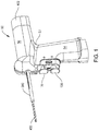
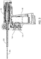
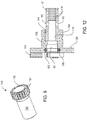
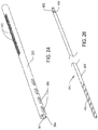
- FIGS 1-3 illustrate a surgical drill 50 of this invention and a drill bit 450 that extends from and is rotated by the drill 50.
- Drill 50 includes a housing 52.
- drill housing 52 is pistol shaped.
- the housing 52 has a grip 54.
- a barrel 56 also part of the housing 52, is located above and extends proximally away from the grip 54.
- Proximally is understood to mean towards the practitioner holding the drill 50; away from the site to which the drill bit 450 is applied.
- “Distally” is understood to mean away from the practitioner holding the drill 50; towards the site to which the drill bit 450 is applied.
- a motor 60 is disposed in the handpiece barrel 56.
- the drill bit 450 is connected to the motor 60 to be rotated by the motor.
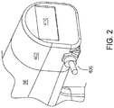
- a display 410 is mounted to the proximal end of the barrel 56.
- Power for energizing the motor 60 is typically provided by a battery (not illustrated) attached to the butt end of the handgrip 54.
- a battery (not illustrated) attached to the butt end of the handgrip 54.
- One such battery is disclosed in the Applicant's US Pub. No. US 2007/0090788/PCT Pub. No. WO 2007/050439 .
- Power may also be supplied from a console over a cable that extends between the console and the drill 50.
- One such console is disclosed in the Applicant's US Pat. Pub. No. US 2006/0074405/PCT Pub. No. WO 2006/039331 .
- Manually actuatable triggers 138 and 139 extend forward from the handgrip 54 below the distal end of the barrel 56.
- a control module 140 Internal into the handgrip 54 is a control module 140.
- sensors Internal to the control module 140 are sensors (not illustrated) that monitor both the state of the motor 60 and the displacement of the triggers 138 and 139. Based on the signals produced by the sensors, control module 140 selectively applies energization signals from the power source to the motor windings 85 ( Figure 7 ) to cause the desired actuation of the motor 60.
- the structure of the control module 140 including the components that regulation the actuation of the motor 60, are not part of the present invention. Further understanding of the design of the control module 140 can be obtained from US Pat. Pub. No. US 2007/0085496/PCT Pub. No. WO 2007/002180 .
- Surgical drill 50 of this invention also includes a probe that is located in close proximity to the drill bit 450.
- the probe is tube shaped, a cannula 380, that circumferentially surrounds the drill bit 450.
- the cannula 380 is slidably mounted to the drill housing 52.
- a transducer assembly 260 ( Figure 16 ) generates signals representative of the position of the distal end of the cannula 380 relative to the drill housing 52. Based on these signals, other components integral with the drill 50 cause data to be presented on the display 410 that indicates the depth of bore formed by the drill bit 450.
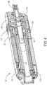
- Motor 60 as seen in Figure 4 , includes a front cap 62 and a back cap 92 that is axially aligned with and spaced distally away from the front cap 62.
- the front cap 62 as seen in Figure 5 , includes a rim 66 that is tube like in shape. Not identified is the step between the proximal section of the rim 66 that has a large outer diameter and the distal section of the rim 66 that has a small outer diameter.
- Three equangularly spaced apart feet 64 two feet seen in Figure 5 , project proximally from the proximal end of rim 66.
- a plate 68 extends over the distal end of the rim 66.
- a boss 70 extends forward from plate 68.
- Boss 70 is formed to define a bore 72 that extends from the distal end of the boss and opens up into the cylindrical void defined by rim 66.
- Front cap 62 is also formed to define a tube shaped sleeve 74.
- Sleeve 74 extends proximally from the proximally directed face of plate 68.
- the front cap 62 is formed so that the sleeve 74 is spaced radially outwardly away from opening in the plate 68 that leads into bore 72.
- the sleeve 74 which is located with the space defined by rim 66, is spaced radially inwardly away from the inner cylindrical wall of the rim.
- the back cap 92 includes a tube like outer sleeve 94.
- Outer sleeve 94 has outer and inner diameters substantially equal to, respectively, the outer and inner diameters of front cap rim 66.
- the back cap 92 also includes an inner sleeve 98.
- the inner sleeve 98 is disposed in the outer sleeve 94 and is spaced radially inwardly from the outer sleeve 94.
- a circularly shaped web 96 also part of back cap 92, extends between the proximal ends of sleeves 94 and 98 to connect the sleeves together. Extending distally forward from web 96, the inner sleeve 98 is shorter in length than the outer sleeve 94. A lip 102 protrudes radially inwardly from the distal end of the inner sleeve 98.
- a tube-shaped lamination stack 78 is disposed between the front cap 62 and the back cap 92.
- the lamination stack 78 is formed from lamination steel.
- One such steel is nickel-iron alloy known as the Carpenter High Permeability "49" Alloy available from the Carpenter Technology Corporation of Wyomissing, Pennsylvania, United States.
- the outer wall of the lamination stack 78 is generally cylindrical.
- the outer wall of the lamination stack 78 has a diameter approximately equal to the common diameter of the rim 66 of the front 66 and outer sleeve 94 of the back cap 92.
- Three equangularly spaced apart longitudinally extending grooves 80 extend inwardly from the outer surface of the lamination stack 78.
- Lamination stack 78 is further formed so plural grooves 82 extend inwardly from the inner surface of the stack (one groove 82 identified).
- the motor windings 85 two ends of which are illustrated in Figure 7 , are seated in the grooves 82.
- the windings 85 extend outwardly beyond the opposed proximal and distal ends of the lamination stack 78.
- the sections of the windings 85 that extend proximally from the lamination stack 78 extend into the annular void space between the outer and inner sleeves 94 and 98, respectively, of the back cap 92.
- the sections of the windings 85 that project forward of the distal end of the lamination stack 78 seat in the annular void space between rim 66 and sleeve 74 of the front cap 62.
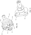
- the rotor 110 of motor 60 is tube like in shape. At the proximal end, the rotor 110 has a foot 112. Foot 112 has a diameter that allows the foot to freely rotate in the circular space defined by the inner surface of lip 102 internal to the back cap 92. Forward of the foot 112, rotor 110 has a torso 114. Torso 114 is shaped so to have an outer surface that, in cross-sectional planes perpendicular to the longitudinal axis through the rotor 110, appears polygonal. The number of faces 115 torso 114 has corresponds to the number of the below discussed magnets 118 disposed over the torso. In Figure 8 , the edge of one face 115 is identified.
- Rotor 110 is further shaped to have a head 116 that extends forward of the torso 114.
- Rotor head 116 has an outer diameter that is located radially inwardly from the faces 115 of the adjacent torso 114.
- a bore 117 extends axially through rotor 110, from the proximal end of the foot 112, to the distal end of the head 116.
- Plural equangularly spaced apart magnets 118 are disposed against the outer surface of the torso 114. Each magnet 118 is disposed over a separate one of the outer faces 115 of the torso 114. In the illustrated version of the invention, six magnets 118 are disposed over the torso 114. Three of the six magnets 118 are seen in Figure 8 .
- a tube shaped sleeve 120 surrounds the magnets 118. Sleeve 120 holds the magnets 118 to the rotor 110.
- Bearing assemblies 122 and 124 rotatably hold the rotor 110 in the bore that extends through the lamination stack 78. (Not illustrated are the inner and outer races of the bearing assemblies 122 and 124.) The inner race of bearing assembly 122 is seated against rotor foot 112. The outer race of bearing assembly 122 is seated against the inner cylindrical surface of the inner sleeve 98 integral with the back cap 92. The inner race of bearing assembly 124 is seated against the rotor head 116. The outer race of bearing assembly 124 is seated against the inner cylindrical surface of sleeve 74 internal to the front cap 62.
- Output shaft 128 extends proximally rearwardly from the rotor 110.
- Output shaft 128 has a tube like stem 130.
- Stem 130 is dimensioned to be compression fit in bore 117 internal to the rotor 110.
- a head 132 is located at the proximal end of stem 130. Head 132 has teeth 134, two teeth identified, that extend radially outwardly beyond the stem 130.
- FIG. 3A When drill 50 of this invention is assembled, it can be seen from Figure 3A that the head 132 of the output shaft 128 is located immediately rearward of the proximal end of the motor back cap 92.
- a tube like motor nut 136 extends over the back cap 92 and projects rearwardly from the back cap 92.
- One of the outer surfaces of the motor nut 136 is formed with threading 137 seen in Figure 4 .
- the threading 137 of the motor nut 136 engages complementary threading on an inner surface of the barrel 56 of the housing 52. (Housing threading not illustrated).
- the motor nut 136 holds the motor 60 and the below described gear train 142 in the housing barrel 56.
- the gear train 142 transfers the rotational moment of the motor rotor 110 to the drill 450.
- the gear train 142 consists of two planetary gear assemblies.
- One planetary gear assembly includes a first disc shaped carrier 148.
- Three equangularly spaced apart planet gears 146 are rotatably mounted to carrier 148 so as to extend forward from the distally directed face of the carrier.
- a bore 150 extends through the center of carrier 148.
- the sun gear integral with carrier 148 that is located rearward of the proximally directed face of the carrier.
- the second planetary gear assembly includes a second disc-shaped carrier, carrier 156.
- Three equangularly spaced apart planet gears 154, two identified in Figure 11 are rotatably mounted to carrier 156 so as to be adjacent the distally directed face of the carrier 156.
- a boss 158 projects rearwardly from the proximally directed face of carrier 156.
- Carrier 156 is further formed to have a center located bore 162. Bore 162 extends through carrier 156 and partially through boss 158. Not identified are the different sections of bore 162. Bore 162 opens into a counterbore 164 formed in boss 158.
- the counterbore 164 which is larger in diameter than bore 162, extends to the proximal end of boss 158.
- carrier 156 Immediately proximal to the open end of bore 162, carrier 156 has a groove 165 that extends radially outwardly from the inner surface of the carrier that defines bore 162.
- An 0-ring 166 is seated in the groove 165 and projects into bore 162. The 0-ring 166 serves as a seal between the below described stationary cannula 602 ( Figure 33 ) and carrier 156.
- Gear train 142 also includes a sleeve 170, identified only in Figure 3A .
- Sleeve 170 abuts and extends proximally away from the back cap 92.
- the sleeve 170 is dimensioned to receive the planetary gear assemblies.
- the inner surface of the sleeve 170 is formed with teeth, (teeth not identified).
- the teeth of planet gears 146 and 154 engage the teeth integral with sleeve 170.
- Sleeve 170 thus functions as the single static ring gear of both planetary gear assemblies.
- gear train 142 When drill 50 is assembled, gear train 142 is located immediately proximal to the motor 60. Head 132 of output shaft is seated between and engages planet gears 146. The output shaft head 132 thus functions as the sun gear for the first planetary gear assembly. In some versions of the invention, the gear train 132 reduces the speed of rotation so that the speed ratio of boss 158 relative to the output shaft 128 is approximately 1:10 to 1:20.
- a spindle 174 is mounted to the boss 158 of the planetary gear assembly to rotate in unison with the boss.
- Spindle 174 is tube like in shape.
- the spindle 174 has an outer diameter that facilitates the press fitting of the spindle in the counterbore 164 internal to boss 158.
- the spindle 174 is formed to have a bore 176 that extends axially through the spindle between the opposed proximal and distal ends of the bore.
- Immediately forward of the proximal end spindle 174 is formed so that teeth 178 project inward into bore 176.
- the teeth 178 extend a distance equal to about one-third the overall length of the bore 176.
- bore 176 is smooth walled.
- the spindle 174 is further formed to have two side bores 180.
- Side bores 180 are diametrically opposed to each other relative to the longitudinal axis through bore 178.
- the side bores 180 are located a short distance forward of the distal ends of teeth 178.
- Each side bore 180 extends from the outer surface of the spindle into bore 176.
- Each side bore 180 has a shape such that, extending radially inwardly from the outer surface of the opening, the diameter of the bore 180 decreases.
- a groove 181 extends inwardly and circumferentially around the outer surface of spindle 174. Groove 181 is located a short distance, less than 1 cm, forward of the proximal end of the spindle 174.
- the coupling assembly includes two balls 184.
- Each ball 184 is seated in a separate one of the side bores 180 formed in spindle 174.
- the components forming drill 50 are arranged so that each ball 184 can partially project through the small diameter opening of the side bore 180 in which the bore is seated.
- balls 184 can extend into, but not completely pass into, the main axial bore 176 formed in the spindle 174.
- Balls 184 are further dimensioned to project outwardly from the spindle 174.
- a lock ring 186 selectively holds the balls 184 to the spindle 174 so the balls are blocked from movement out of the main axial bore 176.
- the lock ring 186 includes a cylindrical collar 188. Immediately proximal to the collar 188, the lock ring has a head 190. For an arc of approximately 300°, head 190 projects radially outwardly beyond the collar 188.
- Lock ring 186 is further formed so that the head 190 is formed with a tapered surface 192 located on the opposed sides of the collar 188. The opposed sides of tapered surface 192 start from the opposed arcuate ends of the head 190. As the sections of the tapered surface 192 extend away from these ends of head 190, tapered surface 192 angles towards the distal end of drill 50.
- Lock ring 186 includes a number of contiguous bores.
- a bore 196 extends proximally from the distal end of collar 188. Bore 196 opens into a bore 198. Bore 198 is smaller in diameter than bore 196.
- a bore 202 extends proximally from the proximal end of bore 198. Bore 202 is tapered. Thus, as bore 202 extends proximally from bore 198, the diameter of bore 202 decreases. Bore 202 opens into a constant diameter bore 204.
- the lock ring 186 is formed so that bore 204 has a diameter equal to the adjacent smallest diameter portion of bore 202.
- the components forming drill 50 are further formed so that bore 204 has a diameter slightly greater than the diameter of spindle 174.
- the diameter of bore 204 is such that when the section of the lock ring 186 in which bore 204 is formed is disposed over the spindle side bores 180, the inner cylindrical wall of the lock ring that defines bore 204 holds balls 184 in the spindle side bores 180. More specifically, the balls 184 are held in the spindle side bores 180 so the balls extend into the main axial bore 176 of the spindle 174.
- the lock ring 186 is formed to have a bore 206. Bore 206 is larger in diameter than bore 204. The lock ring 186 is formed so that bore 206 extends to the proximal of the ring head 190.
- lock ring 186 When the drill 50 is assembled, the lock ring 186 is seated over spindle 174 so that the head 190 of the ring 186 is disposed over the proximal section of the spindle.
- a spring 210 is disposed around the spindle 174 to be located between the spindle and the inner cylindrical wall of the lock ring that defines bore 206.
- One end of the spring seats against a snap ring 212, seen in Figure 3A , seated in spindle groove 181.
- the opposed end of the spring 210 seats against the step internal to the lock ring between bores 204 and 206.
- Spring 212 thus normally urges the lock ring distally forward.
- Lock ring 186 is normally in the position in which the inner surface of the ring that defines bore 204 is positioned around against balls 184. When lock ring 186 is in this position, the coupling assembly is in the locked position.
- a lock actuator 218, best seen in Figure 15 that is moveably disposed in shell 402 moves the lock ring 186 between the locked position and a load position.
- the lock actuator 218 is formed with a rectangular base 220. Two parallel, spaced apart tines 222 extend outwardly from one of the major surfaces of the base. Tines 222 are spaced apart from each other so the lock ring collar 188 can seat between the tines.
- the lock actuator 218 is formed so the tines 222 have coplanar tapered surfaces 224.
- lock actuator 218 is positioned relative to the lock ring 186 so the tapered surfaces 224 of the lock ring abut the spaced apart sections of tapered surface 192 of the lock ring.
- the lock actuator 218 is further formed have a bore 228. Bore 228 extends inwardly from the surface of base 220 from which the tines 222 extend. The bore 228 extends to the opposed surface of the base 220.
- a release button 230 displaces the lock actuator.
- the release button has a stem 232 the end of which is mounted in bore 228 internal to the lock actuator 218.
- the stem 232 of the release button 230 extends through an opening in the shell 402 to which display 410 is mounted.
- the release button has a head 234 located over the end of the stem that is spaced from the actuator.
- the head 234 of button 230 sits in bore 403 formed in shell 402 and extends out of the shell as seen best in Figure 3A .
- a spring 238 is disposed around the portion of stem 232 disposed in bore 403. One end of spring 238 seats against the annular step around the end bore 403. The opposed end of the spring 238 presses against the underside of head 234 integral with the release button 230.
- Spring 238 exerts a force on the release button 230 that results in the button normally holding the lock actuator 218 in a position in which the actuator base 220 is spaced from the lock ring 186. When the lock actuator 218 is in this position, the coupling assembly is in the locked state.
- the transducer assembly 260 is disposed in a pair of opposed shells that are located immediately forward of the distal end of the housing barrel 56.
- One shell, the right shell 262 is seen best in Figure 20 .
- Shell 262 includes a base 264.
- a semi-circular shaped arm 266 protrudes from the base. Arm 266 is dimensioned to fit in the adjacent open end of the housing barrel 56.
- the right shell 262 is formed to have a number of voids.
- One void, void 270 extends inwardly from the face of the shell 262 that seats against the opposed left shell 286.
- Void 270 is circular in shape.
- a circular void 272 extends inwardly from the base of void 270.
- Void 272 has a diameter less than that of void 270.
- the right shell also has a notch 274.
- Notch 274 extends outwardly from the cylindrical wall internal to the shell that defines void 270.
- Another void formed in the right shell is channel 276.
- the right shell 262 is formed so that channel 276 is centered along a longitudinal axis that extends from arm 266 to the distal end of the shell.
- the channel 276 is arcuately shaped such that the base of the channel subtends an arc of approximately 150°.
- Channel 276 intersects void 270.
- Channel 276 is defined by a side wall, (not identified) immediately below void 270 that extends perpendicularly inward from the inner face of shell 262.
- the right shell 262 is further formed so that two semi-circular ribs 278 extend outwardly from the curved interior wall of the shell that defines channel 276.
- One rib 278 is located proximal to void 270.
- the second rib 278 is located distal to void 270.
- the left shell 286, now described with reference to Figure 21 is the second shell in which the components forming transducer assembly 260 are housed.
- the left shell 286 includes a base 288. While not seen in the drawings, the outside of bases 264 and 288 of, respectively, shells 262 and 286, are essentially mirror images of each other.
- the left shell includes arm 290 that extends from the base 288. Arm 290 is essentially a mirror image component of the right shell arm 266.
- the left shell 286 is formed to define a number of voids.
- One of these voids is a circular void 294 that extends inwardly from the inner face of the shell. Void 294 has the same diameter as void 270. When shells 262 are assembled together, voids 270 and 294 are contiguous.
- a circular void 296 extends inwardly from the base of void 294. Void 296 is smaller in diameter that void 294.
- the left shell 286 is also formed to have an outer channel 298 that is located inwardly of the base of void 296. Channel 298 is generally rectangular in shape. The proximal to distal width across channel 296 is less than the diameter of void 296. Channel 298 extends to the bottom of the base 288.
- a circular void 302 is located inwardly of the inner surface of the left shell 286 that defines the base of channel 298.
- the left shell is formed so that voids 294, 296 and 302 are coaxial.
- Void 302 has a diameter less than the diameter of void 296.
- Left shell 286 also has a generally rectangular inner channel 304 that is recessed relative to the outer channel 298. More particularly, the left shell 286 is formed so that void 302 and inner channel 304 have bases that are coplanar.
- the inner channel 304 extends inwardly from the section of the outer channel that is located closest to arm 290.
- Left shell 286 also has a proximally to distally extending channel 306.
- Channel 306 is a mirror image of the right shell channel 276.
- Channel 306 intersects portions of void 294 and outer channel 298.
- the left shell 286 also includes two ribs 308 that project outwardly from the inner surface of the shell that define channel 306. Ribs 308 are mirror image to the ribs 278 integral with the right shell 262.
- a bushing 316 formed of low friction material such as bronze is disposed in the contiguous channels 276 and 306.
- Bushing 316 includes a proximally located foot 318 and a head 324 that is distally located and spaced forward of the foot 318.
- the bushing foot 318 and head 324 are each shaped like a washer that has a truncated outer rim.
- the bushing foot 316 and head 324 are dimensioned to seat against the inner surfaces of shells 262 and 290 that, respectively, define channels 276 and 306.
- the bushing foot 318 and head 324 each has a flat. Only the flat 319 of the bushing foot 318 is identified. The flats abut the flat inner faces of the shells 262 and 290 that define the channels 276 and 306. This flat-against-flat abutment inhibits rotation of the bushing 316.
- the bushing foot 318 and head 324 each is formed with a groove 323 that extends inwardly from the outer curved surface of the component. Grooves 323 identified in Figure 16 . When the drill is assembled, ribs 278 and 308 seat in bushing grooves 323.
- This rib-in-groove seating serves to prevent longitudinal movement of the bushing 316 relative to the shells 262 and 286.
- the bushing foot 318 and head 324 each have a center-located through opening. In Figure 22 only the opening 321 through the head 324 is identified.
- a web 320 also part of bushing 316, extends between foot 318 and head 324. In cross section, in planes perpendicular to the proximal-to-distal longitudinal axis along the bush, web 320 appears arcuate in shape and subtends an arc of approximately 90°.
- the center openings in the foot 318 and head 324 of the bushing open into the space adjacent the web 320.
- a boss 325 identified only in Figure 19 , also part of bushing 320, extends inwardly from the inner surface of head 324. Boss 325 extends into opening 321.
- Transducer assembly 260 includes a gear 326.
- Gear 326 includes a cylindrical base 328 and a coaxial cylindrical head 330.
- Head 330 has a diameter greater than that of the base 328.
- Gear 326 seats in the voids internal to shells 262 and 286.
- Base 328 seats in void 296 internal to the left shell 286.
- the gear head 330 seats in the contiguous voids 270 and 294.
- the gear teeth 332 are understood to project into the contiguous channels 276 and 306. More particularly, the gear teeth are located within the channels 276 and 306 so as to be between the foot 318 and head 324 of bushing 316.
- a shaft 336 extends axially through gear 326.
- the shaft 336 includes a cylindrical foot 338. Adjacent the foot 338 the shaft includes a leg 340. Leg 340 has a diameter greater than that of foot 338. Adjacent the leg 340 the shaft has a cylindrical torso 342.
- the torso 342 has a diameter greater than that of the leg.
- the torso 342 is the portion of the shaft designed to press fit or otherwise be securely seated in the bore that extends axially through the gear 326.
- Shaft 336 has a neck 344 that projects outwardly from the torso. Neck 344 has a shape that is partially cylindrical.
- the radius of curvature of the curved portion of the neck is less than the radius of the torso 342.
- a head 346 also part of the shaft 336, extends outwardly from the neck 344.
- the head 344 has a shape that is partially cylindrical.
- the radius of curvature of the curved surface of the head is less than radius of curvature of the adjacent curved section of the neck 344.
- the shaft 336 is further formed to have a slot 350 that extends longitudinally through the foot 338 and leg 340 and, for manufacturing reasons a short distance into the torso 342. Slot 350 is centered on the common axis through the foot 338, the leg 340 and the torso 342.
- the shaft 336 is further formed so that the neck 344 and head 346 define a common flat 352. As will be apparent, flat 352 is present in head 346 for ease of assembly.
- bearing assembly 354 and 356 rotatably hold the shaft 336 and, by extension, gear 326 in the shells 262 and 286.
- the races of the bearing assemblies are not identified.
- Bearing assembly 354 is seated in void 272 internal to the right shell 262.
- Bearing assembly 354 has an inner race that extends around the shaft foot 338.
- the outer race of bearing assembly 354 is disposed against the cylindrical wall internal to the shell 262 that defines void 272.
- Bearing assembly 356 is seated in void 302 internal to the left shell 286.
- the outer race of the bearing assembly 356 is seated against the inner surface of the left shell 286 that defines void 302.
- the inner race of the bearing assembly is disposed around shaft head 346.
- a potentiometer 360 is disposed in the outer channel 298 of the left shell 286.
- the shaft neck 344 extends through the potentiometer to displace the wiper of the potentiometer.
- Flat 352 abuts an adjacent flat internal to the potentiometer that rotates the wiper internal to the potentiometer.
- Inner channel 304 is provided to serve as the void for containing the wires that extent to the potentiometer 360. The walls that define the inner channel 304 also hold the potentiometer 360 against rotation.
- the transducer assembly 260 also includes a spiral shaped spring 364.
- Spring 364 is disposed in the right shell void 270 so as to be between the base of the void and gear head 330.
- the outer end of spring 364 is seated in notch 274.
- the inner end of the spring 364 extends into the slot 350 internal to the shaft 336.
- a disc 362 is disposed between the surface internal to the right shell 268 that defines the base of void 270 and the spring 364.
- a disc 366 is disposed between the gear head 330 and the spring 364. Not identified are the holes in discs 362 and 366 through which the shaft 336 extends. Discs 362 and 366 provide a low friction interface between spring 364 and the adjacent components of the transducer assembly 260.
- Cannula 380 is a tube shaped structure.
- the cannula 380 has an outer diameter that allows the cannula to closely slip in the bore 117 that extends through the motor rotor 110.
- the components forming drill 50 are further arranged so that the cannula can slip through the openings forming in the foot 318 and head 324 of bushing 316. Also, the cannula can slide over the web 320 of bushing 316.
- indentations extend arcuately across a section of the cannula so as to give the cannula teeth 382, two teeth identified.
- the cannula 380 is shaped so that the teeth 382 mesh with gear teeth 332.
- the cannula is formed so that the teeth extend a distance equal to approximately 30 to 50% of the overall length of the cannula.
- a lumen 381 extends axially through the cannula.
- the wall thickness of the cannula between the outer surface of the cannula and the inner lumen-defining surface is 2 mm or less. In more preferred versions of the invention, this wall thickness is 1 mm or less.
- the distal end of the cannula is formed with a taper. This taper is such that at the most distal end of the cannula the wall thickness of the cannula is even less than the thickness of the wall proximal to this distal end.
- the cannula 380 is also formed so as to have a groove 384 that extends longitudinally along the cannula. Groove 384 is shown extending into the cannula from the surface of the cannula opposite the surface in which teeth 382 are formed. Cannula 380 also is formed with a number of oval through openings 386, two openings identified. The through openings 386 are located forward of teeth 382. Openings 386 extend to the lumen 381 that extends axially through the cannula When the drill 50 of this invention is actuated, the though openings 386 function as ports through which the drilled out material is discharged from the cannula 380.
- Cannula 380 is slidably mounted in the bushing 316.
- the cannula 380 extends through the bushing head 324 and the bushing foot 318.
- the cannula extends distally forward out of the through opening 321 in the bushing head 324.
- the specific section of the cannula mounted in the bushing is the section of the cannula on which teeth 382 are formed.
- the teeth 382 mesh with gear teeth 332.
- spring 364 exerts a torque on shaft 336 that causes the shaft, and by extension gear 326, to rotate.
- the torque urges the shaft to rotate in the clockwise direction when viewed from the perspective of Figure 16 .
- the rotation of gear 326 causes the movement of the cannula. More particularly, the cannula is displaced distally forward, away from the drill housing 52.
- the movement of the cannula stops when the gear teeth 332 abut the teeth free portion of the cannula proximal to the cannula teeth 382. This abutment of the gear teeth against the outer surface of the cannula stops further rotation of the gear 326.
- Display 410 is contained in shell 402 seen best in Figure 2 .
- the shell 402 is mounted to the proximal end of barrel 56.
- the display 410 is mounted to the shell so as to face proximally from the proximal end of the shell.
- Shell 402, display 410 like the other components of the drill of this invention are constructed out of components able to withstand the rigors of process used to sterilize the drill so the drill can be used in surgery.
- the drill 50 is constructed to be able to withstand exposure to an autoclave sterilization process. In an autoclave sterilization process, the drill is placed in an atmosphere saturated with steam (water vapor) at a temperature of 125°C and a pressure of 2 bar.
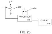
- Figure 25 depicts the basic electrical components of drill 50 that, based on position of the cannula 380, provide an indication of the depth of the bore formed by the drill bit 450. Not identified are the voltage regulating components that ensure the drive signals of the appropriate potentials are supplied to the bore depth displaying components.
- the components that provide the information about bore depth include the potentiometer 360. A voltage is applied to one end of the potentiometer 360. The opposed end of the potentiometer 360 is tied to ground. The voltage present at the wiper of the potentiometer is applied to a signal processor 408. Also shown attached to the signal processor 408 is a zeroing switch 406. In the drawings switch 406 is shown mounted to the display shell 402.
- the signal processor 408 includes a number of components that are not illustrated. These components include a memory. Instructions and data needed by the drill 50 to generate the indications of bore depth are contained in the memory.
- the signal processor 408 also includes a clock or a timer, the purpose of which will become apparent below.
- signal processor 408 Based on changes in the voltage present between the wiper of the potentiometer 360 and one terminal of the potentiometer and the signal from the zeroing switch 406, signal processor 408 generates data representative of the depth of the bore formed by the drill bit 450. Signals representative of the bore depth are applied to the display 410.
- the drill bit includes an elongated shaft 458.
- the components of this invention are arranged so that drill bit shaft 458 has a diameter that is approximately 0.02 to 0.25 mm less than the diameter of cannula lumen 381.
- the relative dimensioning of these two components allows the drill bit 450 both freely rotate and move longitudinally within the cannula 380.
- the cannula has a foot 452. Foot 452, in cross sectional planes perpendicular to the proximal-to-distal longitudinal axis through drill bit 450, is polygonal in shape.
- the foot 452 is shaped so the corner sections between adjacent sides can fit between the teeth 178 of the drive spindle 174. This face-against-teeth arrangement facilitates the transfer of torque from the drive spindle 174 to the drill bit 450.
- a groove 456 is formed in shaft 458.
- Groove 456 extends inwardly from the outer surface of the shaft and circumferentially around the shaft.
- Drill bit 450 is formed so that groove 456 has an arcuate shape. More particularly, the drill bit 450 is formed so that groove 450 can receive balls 184.
- the distal end of drill bit 450 is formed with flutes 460, one flute identified.
- the flutes 460 are designed to drill out the tissue, typically bone, in which the drill 50 is used to form a bore.
- the geometry of the flute 460, including the geometry of the distal end of the drill bit 450 is not part of the present invention.
- Preparation of drill 50 of this invention for use often starts with the releasable attachment of the drill bit 450 to the drill.
- button 230 is pressed inwardly. This results in the movement of the lock actuator 218 laterally, along a plane perpendicular to the longitudinal axis through the drill barrel 56.
- the tapered surfaces 224 move against the adjacent tapered surface 192 of the lock ring 186.
- the force imposed by the lock actuator 218 against the lock ring 186 is sufficient to overcome the force spring 210 places on the lock ring to hold the lock ring in the locked position.
- the lock ring 186 is thus urged proximally.
- the drill bit 450 is inserted into the drill 50.
- the drill bit 450 is inserted through the cannula 380. Once the proximal portion of the drill bit 450 moves proximally past the rotor, this portion of the drill bit moves through the bores 150 and 142 internal to gear train 142 and into the drive spindle 174. As a result of this positioning of the drill bit 450, the corners of the drill bit foot 452 seat between the teeth 178 of the drive spindle 174.
- the finger force applied to button 230 is released. Spring 238 returns the release button 230 and the lock actuator 218 to the locked state.
- Spring 210 then urges the lock ring 186 back to the locked state.
- the tapered surface of the ring that defines bore 202 is urged against the balls.
- This lock ring-against balls abutment urges the balls into the fully seated position in bores 180.
- balls 184 are constrained from outward movement by the surface of the lock ring that defines bore 204. The balls 184 are thus locked in the groove 456 internal to the drill bit 450.
- the seating of balls 184 in groove 456 holds the drill bit to the drive spindle 174.
- drill bit 450 when drill bit 450 is mounted to the housing 52, the drill bit extends out from the housing through the same opening, opening 321 in bushing head 324, from which the cannula 380 extends distally forward.
- the drill 50 is connected to a power supply such as a battery or a power console.
- the drill is first positioned so the distal end of the cannula 380 abuts the surface of the bone around which the bore is to be formed. If the bore is to be formed below a surgical implant such as a plate, after the implant is positioned, the drill is positioned so the cannula abuts the exposed surface of the implant. The implant is formed with an opening through which the drill bit is pressed in order to form the bore. As a result of this initial positioning of the drill 50, the cannula 380 is blocked from further advancement.
- the cannula 380 is static. The drill 50 advances over the cannula 380.
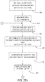
- processor 408 stores the voltage present at the wiper of potentiometer 360 as the zero-state voltage for the procedure.
- the surgeon depresses the appropriate trigger 138 or 139.
- the control module 140 causes drive signals to be applied to the motor that cause the forward rotation of the drill bit, the rotation of the bit that drives the bit into the bone, (step not illustrated).
- Step 484 the drill housing 50 and components inside the housing advance with the drill bit.
- Cannula 380 it is recalled, is blocked from advancing by the continued abutment of the cannula against the tissue or implant surrounding the tissue in which the bore is being formed.
- gear 326 continues to be rotated by the movement of the gear over the cannula 380.
- the rotation of the gear results in the like displacement of the wiper of potentiometer 360. This results in a change in the voltage output of the potentiometer relative to the zero state voltage.
- Step 486 represents the measurement of the voltage of the wiper of the potentiometer as well as the time the measurement is made.
- Step 486 the time the voltage measurement is made is also recorded. These time data are based on the time or clock data from the timer or clock internal to the drill 50. Step 488 is the calculation by the signal processor of the difference between these two voltages. This second voltage is referred to as the present state voltage.
- processor 408 determines the current depth of the bore being formed by drill bit 450. In some versions of the invention, this determination is made by using this voltage difference as the input variable into an algorithm. The output value of this algorithm is the current depth of the bore. Alternatively, the determination of current bore depth in step 490 is made by reference to a set of look up tables. In these tables, the input value is the voltage difference, the output value is bore depth.
- step 490 is the measure of the circumferential distance gear 326 has advanced over the static cannula 380. This distance corresponds to the distance the drill bit 450 has advanced beyond the distal end of the cannula after the zero button was depressed. As discussed below, this distance is generally, but not always, the depth of the bore in the tissue against which the drill bit 450 is applied.
- the signal processor records data indicating the time each determination of bore depth is made. These time data are based on the time the voltage measurement was made.
- Step 492 is the processor presenting on the display 410 the current measurement of bore depth.
- cannula 380 appears to retract into and beyond the shells 262 and 282 that contain the transducer assembly 260.
- the proximal section of the cannula retracts into rotor bore 117.
- cannula 380 is provided with a component that limits the extent to which the drill 50 is allowed to advance over the cannula. This is to prevent the rapidly spinning output shaft 128 from pressing against the static cannula 380.
- a static ring (not illustrated) is disposed over and rigidly mounted to the cannula.
- the ring is positioned so that, once the drill 50 advances a certain distance of the cannula the front face of the drill, actually the front face of bushing head 324 abuts this ring. This drill-against-ring abutment prevents the drill from advancing to a position in which the output shaft 128 presses against the cannula 380.
- drill 50 is designed so that drill can advance over the cannula at least 1 cm, and more typically at least 5 cm and more preferably at least 10 cm. In most versions of the invention, drill 50 is designed so that the drill can advance over the cannula a distance at least equal to 0.5 cm more than the depth of the deepest bore the drill is intended to form.
- step 494 the processor 408 determines if the current bore depth is greater than a previously stored deepest bore depth. If the evaluation of step 494 tests positive, the processor considers the drill 50 to be in a state in which the drill bit 450 is advancing. In a step 496 the processor resets the value of the deepest bore depth to the just calculated current bore depth.
- step 498 Another step executed if the evaluation of step 494 tests positive is the determination of a breakthrough depth, step 498.
- the breakthrough depth is the depth of the bore at the moment the drill bit has broken through the bone. The breakthrough depth is thus the depth of the fully formed bore in the bone.
- one variable used to determine breakthrough depth is the time the deepest bore depth was reached.
- breakthrough depth is the deepest bore depth at a fixed time prior to when the drill bit was at the deepest bore depth.
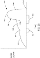
- Plot 530 represents the depth of the bore as measured by the transducer assembly over time.
- Section 532 of the plot represents that, as the drill bit 450 is advanced through bone, the depth of the bore over time advances at a relatively slow speed.
- Indentation 534 in section 532 represents that while the bit 450 is being advanced through the bone, there may be instances in which the current depth of the drill bit may be momentarily less than the bore depth. This can occur if the surgeon momentarily retracts and then resets the drill bit 450.
- time period 533 after the bit is retracted until the drill bit tip again engages bone, the evaluation of step 494 tests negative.
- Point 538 represents the bore depth and time at which the drill bit 450 breaks through the bone. At this time, the surgeon is still applying an axial force on the drill to advance the bit 450. Accordingly, once breakthrough occurs, the drill bit continues to advance for a short period of time. Soft tissue places less resistance on the advancement of the bit than bone. Accordingly, the advancement of bit 450 during this time period is at a speed higher than the speed at which the advancement previously occurred. This high speed advancement of the bit is represented by section 540 of plot 530. Point 542 represents the bore depth and time at which the surgeon stops advancing the drill bit. This depth is referred to as the final penetration depth. This depth is the deepest bore depth value set in the last execution of step 496.
- Section 544 of plot 530 represents the complete withdrawal of the drill bit 450 from the patient.
- Point 546 represents that, as a result of the withdrawal of the drill bit and the retraction of the drill 50 from over the cannula 380, the processor 408 calculates the bore depth as being back at a zero depth state. It should be understood that in this withdrawal process, the surgeon typically actuates the drill bit. Often the surgeon performs this step by reverse driving the drill bit 450. In the described version of the invention, the motor 60 is run in verse by depressing trigger 139.
- the determination of step 498 is based on the start time of a time frame the end of which is the time at point 542 the surgeon starts the final retraction of the drill 450.
- This time frame is represented by bracket 535.
- the start time of this time frame is represented by point 536 on the bore depth plot 530.
- This start time of the time frame is prior to when the breakthrough occurred, point, 538.
- the margin of error between the bur depth at the beginning of this time frame, point 536 on plot 530, and the bur depth at point 538 is typically within an acceptable range of accuracy for providing a measure of bore depth at drill bit break through.
- step 498 processor 408 continues to execute step 498.
- the breakthrough depth is determined by first assigning the time at which the deepest bore depth was measured as the end time for time frame. Based on this end time, a fixed time value, the time value of the time frame, is subtracted from the end time to determine the start time. Then the bore depth at the start time for this time frame is assigned the value of the breakthrough depth. It should be understood that as long as the bore is advancing through the bone, the breakthrough bore depths determined in the plural executions of step 498 represent neither the breakthrough bore depth nor the actual depth of the bore in the bone. Only the depth determination made during the last execution of step 498, which is based on when the drill bit 450 reached the final penetration depth, represents the actual depth of the bone at break through.
- step 486 represents that the measurement of bore depth, the display of current bore depth, the determination of whether or not the measured depth is the deepest bore depth and the calculation of a breakthrough depth occur repeatedly while the drill bit 450 is advanced through bone.
- step 494 If the evaluation of step 494 tests negative, then the surgeon either has momentarily retracted the drill bit 450 or completed the process of drilling the bore. In either situation, steps 494-498 are not executed.
- step 504 is executed.
- the processor evaluates whether or not based on the current measurement of bore depth measurement the drill bit indicates the drill bit has been retracted to a zero depth relative to the surface of the bone.
- step 504 If the evaluation of step 504 is negative, the processor 408 considers the drill to be in a state in which the drill bit has been momentarily retracted, the period 536 of indentation 534, or the drill bit is being subjected to complete retraction, the period of section 544 of plot 530. In either case, the drill bit 450 is still in bone. The processor 408 loops back to step 486.
- step 504 If the evaluation of step 504 tests positive, then the drill bit 450 is fully retracted from the bone.
- Processor 408 interprets the drill 50 being in this state as an indication that the bore was completely formed in the bone. Accordingly, in a step 506, the processor presents on the display the last calculated breakthrough depth as the measured depth of the bore in the bone.
- Drill 50 of this invention thus provides data that accurately represents the depth of the bore the drill is used to form and provides these data without appreciably interfering with the view of the drill bit or the tissue surrounding the drill bit.
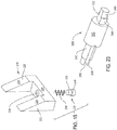
- Figure 29 depicts how the drill 50 of this invention may be used with a drill guide 550.
- the drill guide 550 is used when the drill 450 is used to form bores designed to receive screws used to hold a locking style plate to the outer surface of section of bone. This type of plate is used to hold fractured sections of bone together.
- the locking plate is formed with small 1 through openings designed to receive the screws. The through openings are provided with threading designed to hold the screws fitted in the openings to the plate.
- Drill guide 550 is generally cylindrical is shape.
- a foot 552 forms the most distal section of the drill guide 550.
- the outer surface of the foot 552 is formed with threading (not identified).
- the foot threading is designed to engage with the threading in the plate openings. This allows the drill guide 550 to be temporarily secured in each of the plate openings.
- Proximal to the foot 552 the drill guide has a trunk 554.
- Trunk 554 has an outer diameter greater than that of the foot 552.
- a neck 556 extends rearward from the proximal end of the trunk 554.Forward of the neck 556, drill guide 550 has a head 560.
- the head 560 is largest diameter section of the drill guide 550.
- a distal bore 564 extends through the foot 552 and trunk 554 and a short distance into the neck 556.
- Distal bore 564 like the cannula lumen 381 is dimensioned to receive the drill bit 450 so the drill bit can rotate in the bore 564.
- the distal bore 564 opens into a proximal bore 568.
- the drill guide 550 is shaped so that proximal bore 568 has a diameter greater than that of distal bore 564. More specifically, the proximal bore 568 has a diameter that allows the cannula 380 to closely slip fit in the bore 568.
- the proximal bore 568 extends through the neck 556 and head 560 to the proximal end of the head 560 which is the proximal end of the drill guide 550.
- Drill guide 550 is further formed so that proximal to the foot a number of oval shaped openings 566 extend through the trunk 554 into the distal bore 564. Openings 566 serve the same function as openings 386 internal to the cannula 380.
- a drill 50 with drill guide 550 is used by initially configuring the drill as if the drill is to be used without the drill guide.
- the foot 552 of the drill guide 550 is screwed into one of the bore holes of the plate adjacent which the bore is to be formed. Once the plate is properly positioned, drill bit 450 is inserted into first bore 568 and then bore 564 of the drill guide 550.
- the cannula 380 eventually abuts the step internal the drill guide between the bores 564 and 568. This abutment of the cannula 380 stops the simultaneous advancement of the cannula with the drill bit 450. As the drill bit and drill continue to advance, the advancement of the drill cause the drill to move over the cannula 380. Gear 326 rotates as the gear advances over the cannula 380.
- the drill bit 450 abuts the bone to which the drill bit is to be applied.
- This bit-against-bone abutment stops further advancement of the drill bit and the drill 50.
- the drill 50 is set to form the bore in the bone.
- the process described with respect to Figures 27A and 27B is performed to both form the bore and simultaneously provide a measure of bore depth.
- the cannula is held static by the continued abutment of the cannula against the step internal to the drill guide.
- step 482 the zeroing of the cannula position is performed when the drill is in a state in which the cannula has abutted the step internal to the drill guide and the drill bit has first abutted the underlying bone.
- the calculated difference in potentiometer voltage again represents the distance the drill 50 has advanced toward the distal end of the cannula. This distance again corresponds to the depth of the bore the drill bit has formed in the bone.
- drill guide 550 By providing drill guide 550, one can use drill 50 of this invention to precisely orient the drill bit relative to the plate adjacent which the bore is to be formed. This ensures the resultant bore will have the correct orientation relative to the screw thread of the plate.
- FIG. 31 depicts an alternative housing 582 for the drill of the invention.
- display 584 is mounted to the portion of the housing that contains the transducer assembly.
- Figure 32 depicts a portion of an alternative drill 50a of this invention.
- the drill bit is not shown disposed in the motor rotor.
- the drill 50a includes the housing 582 and display 584 described above.
- Drill 50a also includes a motor 60a.
- Motor 60a is substantially identical to the first described motor 60.
- Motor 60a includes an additional component, a static cannula 602 seen best in Figure 33 .
- Static cannula 602 includes a tubular trunk 610. Trunk 610 has an outer diameter less than the diameter of the inner surface of rotor 110 that defines bore 117. At the proximal end of the trunk 610 a ring like head 608 protrudes radially outwardly and circumferentially around the trunk.
- the outer cylindrical surface of the head 608 is typically provided with threading (not illustrated). More particularly, the head 610 is shaped to seat in the bore 72 internal to the front cap boss 70.
- a tail 612 extends proximally from the proximal end of the trunk 612.
- Stationary cannula 602 is formed so that the tail has an outer diameter less than that of the trunk 610. More particularly the outer diameter of tail 612 is such that the tail can seat in and be spaced inwardly from the surface internal to the boss 158 of carrier 156 that defines bore 162.
- the static cannula 602 is further formed so that the inner wall that defines the bore 618 that extends through tail 612 has a diameter sufficient to allow the drill bit 450 to seat and freely rotate in the tail.
- Static cannula 602 has two contiguous bores that extend axially through the cannula.
- a bore 616 extends proximally from the distal end of the head 608, through the head and to the proximal end of the trunk 610. Bore 616 opens into a bore 618. Bore 618 extends through the tail 612 of the cannula 602and forms the opening at the proximal end of the cannula. Bore 618 it should be understood has a diameter less than the diameter of bore 616.
- front cap 62 is formed so the inner surface of boss 70 that defines bore 72 is formed with threading (not illustrated).
- the stationary cannula 602 is fixedly secured in the rotor bore 117 by rotating the cannula 602 so the threading around the cannula head 608 engages the threading internal to boss 70.
- Drill 50a is used in the same manner in which the first described drill 50 is used. The only appreciable difference in use is that when the drill bit 450 is fitted to drill 50a, the bit extends through bores 616 and 618 internal to the static cannula 602 prior to extending into the spindle 174.
- a benefit of drill 50a is that the static cannula 602 functions as a barrier between the ambient environment and moving components of the motor 60a. This barrier prevents the fluids and debris that are present when the drill 50a is employed from contacting the moving components of the motor 60a.
- the motor may be a pneumatic motor or a hydraulic motor.
- the probe that extends forward from the drill be a cannula that essentially circumferentially surrounds the drill bit.
- the probe may be a rod that subtends a relatively small arc around the drill bit.
- the probe may consist of plural arcuately spaced apart rods.
- a stop, that subtends a larger arc may be located at the distal end of the rod (or rods).
- the inner surface of the probe, the surface adjacent the drill bit is spaced no more than 2 mm from the drill bit.
- the outer surface of the probe, the surface spaced furthest away from the drill bit is located a maximum of 5 mm away from the drill bit.
- this invention is not limited to drills in which the transducer assembly that measures displacement of the drill relative to the probe includes a gear that engages the probe or a potentiometer that measures gear rotation.
- a linear variable differential transformer may function as the transducer that measures the relative movement of the drill to the probe and provides a signal representative of this movement. The sensor signal will vary based on the relative location of the magnet to the sensor. Based on changes in this sensor signal, the signal processor is able to determine the movement of the drill relative to the probe.
- the transducer may be a transducer that generates signals as a function of the transit of the teeth past the sensor.
- One such sensor is the ATS605LSG Dual Output Differential Speed And Direction Sensor available from Allegro MicroSystems of Worcester, Massachusetts.
- the transducer outputs a distinct pulse signal.
- the number of pulses emitted by the transducer is representative of the number of teeth that move past the sensor.
- the number of teeth that move past the sensor is corresponds to the distance the drill 50 has advanced over the cannula 380.
- the senor may be an optical sensor.
- the probe is formed with marking that are readable by the sensor.
- Other sensor capable of providing a signal representative of the movement of one components relative second component may also be employed.
- the components of the transducer assembly 260 be removably mounted to the drill housing 52.
- a benefit of these versions of the invention is that these removable components do not need to be designed to withstand the rigors of repeated sterilization processes.
- the probe is built into the removable module that includes the transducer assembly.
- the probe is removably attached to the drill housing.
- the elongated groove that extends laterally along the outer surface of the probe, groove 384 of cannula 380 may start at a location distal to the proximal end of the probe or terminate at a location proximal to the distal end of the probe.
- the abutment of the boss 325 against the end or ends of the groove limits the movement of the probe relative to the drill.
- the common opening in the drill housing 52 through which both the cannula 380 and drill bit 450 extend distally forward need not always be in the bushing that supports the cannula for the slidable movement. Similarly, this common opening may not always be an opening formed in a component that forms part of transducer assembly.
- the bushing may not always be the single piece assembly described with respect to the primary version of the invention.
- the bushing may consist of two or more spaced apart members that hold the probe so as to allow longitudinal movement of the probe while inhibiting movement away from the axis of the drill bit 450.
- This flexure if it were allowed to occur, could adversely affect the ability of the drill to provide an accurate measure of bore depth. A more serious effect of allowing this flexure is that it could result in the probe pressing against the rotating drill bit.
- the bushing assembly should restrain the probe from lateral movement, side-to-side movement, along a distance that is at least 1 cm long, more often at least 1.5 cm in length and more preferably still at least 2 cm in length.
- this force may be provided by a spring that applies a longitudinal force directly on the probe. It is likewise within the scope of this invention that the assembly that provides this biasing force be one that relies on a magnetic or electromagnet force to urge the probe distally forward. It should thus be appreciated that it falls within the scope of this invention to provide a biasing member that urges the probe distally forward that is not integral with the transducer assembly.
- the biasing member that urges the probe distally forward may not be part of the transducer assembly.
- the biasing member may be a helical spring disposed in the rotor bore that pushes against a proximal portion of the probe.
- gear train sometimes referred to as a transmission
- the gear train may have a structure different from what has been described.
- the gear train include a single planetary gear assembly or three or more planetary gear assemblies.
- the transmission may not always physically be located between the motor 60 and the drive spindle 174, the component to which the drill bit 450 is coupled.
- the components may be arranged so that the drive spindle is located between the motor and the transmission.
- the transmission reduces the rotational speed of the drive spindle relative to the speed of the motor rotor. It is within the scope of this invention that the transmission may actually serve to increase the speed of rotation of the drive spindle relative to that of the motor. Similarly, in some versions of the invention, the transmission may only serve to transfer the rotational motion of the motor rotor to the drive spindle without causing either an increase or decrease in rotational speed of the drive spindle relative to the rotor.
- this invention is not limited to a drill constructed so that the rotor that drives the drill bit and in which both the drill bit are seated is the rotor internal to the drill motor.
- An alternative drive of this invention may be one in which the motor rotor and drill bit-receiving rotor are separate from each other.
- an alternative drill of this invention may be constructed so that the motor is contained with the handgrip of the drill housing.
- the rotor that both rotates the drill bit and that receives the probe is rotatably contained with the barrel of the housing.
- the motor has a rotor is disposed with the windings.
- a gear assembly transmits the rotational moment of this rotor to a second rotor.
- This second rotor is the rotor to which the drive spindle is connected.
- this gear assembly also functions as the transmission that steps down the rotational moment so the rotor through which the drill bit and probe extend rotate at a speed slower than the rotational speed of the motor drive shaft.
- the motor rotor and drill bit-receiving rotor turn at the same speed.
- a gear assembly similar to gear assembly similar to gear assembly 142 steps down the speed of the drive spindle, the component to which the drill bit 450 is actually coupled, so the drive spindle rotates at a speed less than the speed at which the rotor turns.
- the drill may not include a rotor with a bore through which the drill bit extends and in which the probe is slidably received. It falls within the scope of the drill of this invention to construct the drill so that motor is located proximal to the coupling assembly that connects the drill bit 450 for rotation by the motor.
- components other than a rotor may transfer torque from the output shaft of the motor to the spindle or other component to which the drill bit is removably connected. It should be understood that in these versions of the invention, it may not be necessary to include a rotor with a bore that transfers torque to the drill bit coupling assembly.
- the probe 380 extends distally forward from the handpiece through the opening through which the drill bit 450 extends.
- a bushing assembly is most likely present to prevent lateral movement of the probe.
- the coupling assembly used to releasably hold the drill bit to the motor 60 be different from what has described.
- one alternative coupling assembly that can be incorporated into the drill of this invention is a coupling assembly with a collet that has flexible feet.
- a collar that is selectively moveable holds the feet against the drill bit so as to place the coupling assembly in the locked state.
- by moving the collar the feet are able to flex away from the drill bit. This facilitates the removal of the drill bit and the loading of a new drill bit.
- This type of coupling assembly can be obtained from US Pat. Pub. No. 2002/0058958/PCT Pub. No. WO 2001/0060261 .
- the drive spindle may be integral with the motor rotor.
- the coupling assembly essentially directly secures the drill bit 450 to the motor rotor 60 so the drill bit rotates in unison with the motor rotor.
- the housing be pistol shaped.
- processor 408 determines and displays the final value of the depth of the bore formed in the bone based on the surgeon's determining that the drill bit 450 has fully bored through the bone.
- the input cue that triggers the final determination by the processor 408 of bore depth may be different from what has been described.
- the input cue that the drill bit 450 has broken through the bone may be based on one or more of the input variables: depth of bore; speed of advancement of drill bit through the bone, including changes in acceleration; torque output by the motor; current drawn by the motor; or motor speed.
- the variables used to determine bore depth may include one or more above the listed variables.
- the display on which the data regarding bore depth is presented by built into the handpiece may be on a remote console.
- the display can be part of image presented on the remote console used to source power to the motor 60.
- the processor that, in response to the signals output by the transducer assembly 260 determines the depth of the bore may likewise built into the remote console that includes the display.
- a cable from the drill housing 52 to the console includes the conductors over which the signals from the transducer assembly 260 are forwarded to the processor.
- the method of determining breakthrough of a bore using the surgical drill of this invention described with respect to Figures 27A and 27B maybe practiced using assemblies for determining bore depth other than the assembly of this invention.
- this method can be used with an assembly that measures bore depth with a probe that is spaced more than 5 mm away from the drill bit.
- the sensor that measures depth of drill penetration be an assembly that, by monitoring the time it takes for waves to reflect back to the transducer assembly determine the advance of the drill to the bone and, by extension, the depth of drill bit penetration.
- step 498 of determining breakthrough depth may only be determined once, after the comparison of step 504 indicates that the determined depth has returned to the zero depth.
Claims (13)
- Perceuse chirurgicale (50, 50a) pour actionner un foret (450), la perceuse chirurgicale incluant :un logement (52, 582) ;un moteur (60, 60a) disposé dans le logement ;un rotor (110) qui est disposé rotatif dans le logement et qui fait partie du ou est connecté au moteur de telle sorte que l'actionnement du moteur résulte en la rotation du rotor, le rotor ayant des extrémités proximale et distale opposées ;un ensemble (174, 184, 186, 218) d'accouplement disposé dans le logement, l'ensemble d'accouplement étant adapté à coupler de façon libérable un foret (450) configuré pour former un alésage dans un tissu vivant au rotor (110) de telle sorte que le foret tourne à la rotation du rotor ;une sonde (380), la sonde étant montée coulissante sur le logement de façon à s'étendre vers l'avant depuis le logement, la sonde ayant une extrémité distale adaptée à un placement contre un tissu ; etun ensemble (260) de transducteur monté sur le logement pour produire un signal représentatif de la distance sur laquelle le logement (52, 582) se déplace par rapport à l'extrémité distale de la sonde (380) lorsque le foret (450) est fait avancer dans le tissu ;dans lequelle rotor (110) est formé avec un alésage (117) dimensionné pour recevoir une section proximale du foret (450) et une section proximale de la sonde (380) ;l'ensemble (174, 184, 186, 218) d'accouplement est situé dans le logement adjacent à l'extrémité proximale du rotor (110) de telle sorte que, lorsque le foret (450) est couplé au rotor (110) de moteur, une section proximale du foret est couplée à l'extrémité proximale du rotor et le foret s'étend à travers l'alésage (117) de rotor et le foret s'étend vers l'avant hors de l'extrémité distale du rotor vers le tissu contre lequel le foret doit être appliqué ; etla sonde est montée sur le logement (52, 582) de façon à avoir une section proximale qui est apte à se déplacer longitudinalement dans l'alésage (117) du rotor (110) et une section distale qui s'étend en avant du rotor de façon à être située adjacente à une extrémité distale du foret (450).
- Perceuse chirurgicale (50, 50a) selon la revendication 1, dans laquelle ledit ensemble d'accouplement inclut :un arbre creux (174) qui est disposé rotatif dans le logement (52, 582), ledit arbre creux ayant des caractéristiques adaptées à recevoir le foret (450) de telle sorte que le foret tourne à l'unisson avec ledit arbre creux et ledit arbre creux étant connecté au rotor (110) de façon à tourner à l'actionnement du rotor ; etdes caractéristiques de maintien (184) qui couplent de façon libérable le foret audit arbre creux (174).
- Perceuse chirurgicale (50, 50a) selon la revendication 2, dans laquelle :le rotor (110) et ledit arbre creux (174) sont séparés l'un de l'autre ; etune transmission (142) est connectée entre le rotor (110) et ledit arbre creux (174) pour transférer le mouvement de rotation du rotor à l'arbre creux de telle sorte que l'arbre creux tourne à la rotation du rotor ;dans laquelle, comme une option :
ladite transmission (142) est située entre le rotor (110) et ledit arbre creux (174) et ladite transmission est formée avec un alésage traversant (150, 162) à travers lequel le foret (450) s'étend. - Perceuse chirurgicale selon la revendication 3, dans laquelle ladite transmission (142) est configurée pour abaisser la vitesse de rotation dudit arbre creux (174) de telle sorte que l'arbre creux tourne à une vitesse inférieure à la vitesse de rotation du rotor (110).
- Perceuse chirurgicale (50, 50a) selon l'une quelconque des revendications 1 à 4, dans laquelle la sonde est une canule (380) qui entoure circonférentiellement le foret (450) ;
dans laquelle, comme une option, ladite canule (380) est formée avec au moins une ouverture (386) à travers laquelle des débris générés lors d'un percement par le foret (450) sont déchargés de ladite canule. - Perceuse chirurgicale (50, 50a) selon l'une quelconque des revendications 1 à 5, dans laquelle l'ensemble (260) de transducteur inclut :un élément mobile (36) qui est monté mobile sur le logement (52, 582) et adapté à engager la sonde (380) et se déplacer selon le déplacement du logement par rapport à la sonde ; etun transducteur (360) connecté audit élément mobile et configuré pour générer un signal variable comme une fonction du mouvement dudit élément mobile.
- Perceuse chirurgicale (50, 50a) selon la revendication 6, dans laquelle ledit élément mobile (326) est monté rotatif sur le logement de façon à, selon le déplacement du logement par rapport à la sonde (380), tourner ; ou dans laquelle
la sonde (380) est formée avec des dents (386) ; et
ledit élément mobile (326) est une roue dentée qui engage les dents de ladite sonde. - Perceuse chirurgicale (50, 50a) selon l'une quelconque des revendications 6 ou 7, dans laquelle ledit transducteur (360) est un potentiomètre.
- Perceuse chirurgicale (50, 50a) selon l'une quelconque des revendications 1 à 8, dans laquelle l'ensemble (260) de transducteur est monté sur le logement (52, 582) et apte à subir un processus de stérilisation auquel le logement est soumis ; et/ou
la perceuse chirurgicale (50, 50a) incluant en outre un processeur (408) et un afficheur (410) montés sur le logement (52, 582), ledit processeur configuré pour recevoir le signal provenant de l'ensemble (260) de transducteur et, sur la base du signal, amener à ce que soit présentée sur ledit afficheur (410) une indication de la profondeur de l'alésage formé par le foret (450) ; et/ou
dans laquelle le moteur (60, 60a) est un parmi le groupe consistant en : un moteur électrique ; un moteur hydraulique ; et un moteur pneumatique. - Perceuse chirurgicale selon l'une quelconque des revendications 1 à 9, dans laquelle la sonde (380) et l'ensemble (260) de transducteur sont montés amovibles sur le logement.
- Perceuse chirurgicale (50, 50a) selon l'une quelconque des revendications 1 à 10, incluant en outre un élément de poussée (364) qui s'étend entre le logement (52, 582) et la sonde (380) pour placer une force sur la sonde qui pousse l'extrémité distale de la sonde à l'opposé du logement ;
dans laquelle, comme une option, ledit élément de poussée (364) est un ressort. - Perceuse chirurgicale selon la revendication 11, dans laquelle ledit élément de poussée est situé interne à l'ensemble (260) de transducteur.
- Perceuse chirurgicale (50, 50a) selon l'une quelconque des revendications 1 à 12, dans laquelle, au moins le long de la section de 10 mm la plus distale de la sonde (380), la sonde (380) s'étend sur un maximum de 5 mm vers l'extérieur depuis le foret (450) ; et/ou
dans laquelle le moteur (60, 60a) est un moteur électrique qui inclut des enroulements (85) et le rotor (110) avec l'alésage (117) est disposé à l'intérieur des enroulements de moteur et des aimants (118) sont montés sur le rotor (110) de telle sorte le rotor fonctionne comme le rotor du moteur (60, 60a).
Priority Applications (2)
| Application Number | Priority Date | Filing Date | Title |
|---|---|---|---|
| EP20203431.0A EP3808287B1 (fr) | 2015-09-03 | 2016-09-01 | Perceuse chirurgicale motorisée présentant une jauge de profondeur intégrée qui comprend une sonde qui coulisse sur le trépan |
| EP23189640.8A EP4245231A3 (fr) | 2015-09-03 | 2016-09-01 | Perceuse chirurgicale motorisée présentant une jauge de profondeur intégrée qui comprend une sonde qui coulisse sur le trépan |
Applications Claiming Priority (2)
| Application Number | Priority Date | Filing Date | Title |
|---|---|---|---|
| US201562213916P | 2015-09-03 | 2015-09-03 | |
| PCT/US2016/049899 WO2017040783A1 (fr) | 2015-09-03 | 2016-09-01 | Perceuse chirurgicale motorisée présentant une jauge de profondeur intégrée qui comprend une sonde qui coulisse sur le trépan |
Related Child Applications (3)
| Application Number | Title | Priority Date | Filing Date |
|---|---|---|---|
| EP20203431.0A Division EP3808287B1 (fr) | 2015-09-03 | 2016-09-01 | Perceuse chirurgicale motorisée présentant une jauge de profondeur intégrée qui comprend une sonde qui coulisse sur le trépan |
| EP20203431.0A Division-Into EP3808287B1 (fr) | 2015-09-03 | 2016-09-01 | Perceuse chirurgicale motorisée présentant une jauge de profondeur intégrée qui comprend une sonde qui coulisse sur le trépan |
| EP23189640.8A Division EP4245231A3 (fr) | 2015-09-03 | 2016-09-01 | Perceuse chirurgicale motorisée présentant une jauge de profondeur intégrée qui comprend une sonde qui coulisse sur le trépan |
Publications (2)
| Publication Number | Publication Date |
|---|---|
| EP3344165A1 EP3344165A1 (fr) | 2018-07-11 |
| EP3344165B1 true EP3344165B1 (fr) | 2020-12-30 |
Family
ID=56896838
Family Applications (3)
| Application Number | Title | Priority Date | Filing Date |
|---|---|---|---|
| EP16763694.3A Active EP3344165B1 (fr) | 2015-09-03 | 2016-09-01 | Perceuse chirurgicale motorisée présentant une jauge de profondeur intégrée qui comprend une sonde qui coulisse sur le trépan |
| EP20203431.0A Active EP3808287B1 (fr) | 2015-09-03 | 2016-09-01 | Perceuse chirurgicale motorisée présentant une jauge de profondeur intégrée qui comprend une sonde qui coulisse sur le trépan |
| EP23189640.8A Pending EP4245231A3 (fr) | 2015-09-03 | 2016-09-01 | Perceuse chirurgicale motorisée présentant une jauge de profondeur intégrée qui comprend une sonde qui coulisse sur le trépan |
Family Applications After (2)
| Application Number | Title | Priority Date | Filing Date |
|---|---|---|---|
| EP20203431.0A Active EP3808287B1 (fr) | 2015-09-03 | 2016-09-01 | Perceuse chirurgicale motorisée présentant une jauge de profondeur intégrée qui comprend une sonde qui coulisse sur le trépan |
| EP23189640.8A Pending EP4245231A3 (fr) | 2015-09-03 | 2016-09-01 | Perceuse chirurgicale motorisée présentant une jauge de profondeur intégrée qui comprend une sonde qui coulisse sur le trépan |
Country Status (8)
| Country | Link |
|---|---|
| US (3) | US10695074B2 (fr) |
| EP (3) | EP3344165B1 (fr) |
| JP (3) | JP6862429B2 (fr) |
| KR (1) | KR20180048848A (fr) |
| CN (2) | CN108348264B (fr) |
| AU (3) | AU2016317908B2 (fr) |
| CA (1) | CA2997315A1 (fr) |
| WO (1) | WO2017040783A1 (fr) |
Families Citing this family (389)
| Publication number | Priority date | Publication date | Assignee | Title |
|---|---|---|---|---|
| US20070084897A1 (en) | 2003-05-20 | 2007-04-19 | Shelton Frederick E Iv | Articulating surgical stapling instrument incorporating a two-piece e-beam firing mechanism |
| US9060770B2 (en) | 2003-05-20 | 2015-06-23 | Ethicon Endo-Surgery, Inc. | Robotically-driven surgical instrument with E-beam driver |
| US11890012B2 (en) | 2004-07-28 | 2024-02-06 | Cilag Gmbh International | Staple cartridge comprising cartridge body and attached support |
| US8215531B2 (en) | 2004-07-28 | 2012-07-10 | Ethicon Endo-Surgery, Inc. | Surgical stapling instrument having a medical substance dispenser |
| US7934630B2 (en) | 2005-08-31 | 2011-05-03 | Ethicon Endo-Surgery, Inc. | Staple cartridges for forming staples having differing formed staple heights |
| US7669746B2 (en) | 2005-08-31 | 2010-03-02 | Ethicon Endo-Surgery, Inc. | Staple cartridges for forming staples having differing formed staple heights |
| US11246590B2 (en) | 2005-08-31 | 2022-02-15 | Cilag Gmbh International | Staple cartridge including staple drivers having different unfired heights |
| US9237891B2 (en) | 2005-08-31 | 2016-01-19 | Ethicon Endo-Surgery, Inc. | Robotically-controlled surgical stapling devices that produce formed staples having different lengths |
| US10159482B2 (en) | 2005-08-31 | 2018-12-25 | Ethicon Llc | Fastener cartridge assembly comprising a fixed anvil and different staple heights |
| US11484312B2 (en) | 2005-08-31 | 2022-11-01 | Cilag Gmbh International | Staple cartridge comprising a staple driver arrangement |
| US20070106317A1 (en) | 2005-11-09 | 2007-05-10 | Shelton Frederick E Iv | Hydraulically and electrically actuated articulation joints for surgical instruments |
| US8820603B2 (en) | 2006-01-31 | 2014-09-02 | Ethicon Endo-Surgery, Inc. | Accessing data stored in a memory of a surgical instrument |
| US8708213B2 (en) | 2006-01-31 | 2014-04-29 | Ethicon Endo-Surgery, Inc. | Surgical instrument having a feedback system |
| US7845537B2 (en) | 2006-01-31 | 2010-12-07 | Ethicon Endo-Surgery, Inc. | Surgical instrument having recording capabilities |
| US7753904B2 (en) | 2006-01-31 | 2010-07-13 | Ethicon Endo-Surgery, Inc. | Endoscopic surgical instrument with a handle that can articulate with respect to the shaft |
| US11224427B2 (en) | 2006-01-31 | 2022-01-18 | Cilag Gmbh International | Surgical stapling system including a console and retraction assembly |
| US11278279B2 (en) | 2006-01-31 | 2022-03-22 | Cilag Gmbh International | Surgical instrument assembly |
| US20120292367A1 (en) | 2006-01-31 | 2012-11-22 | Ethicon Endo-Surgery, Inc. | Robotically-controlled end effector |
| US20110290856A1 (en) | 2006-01-31 | 2011-12-01 | Ethicon Endo-Surgery, Inc. | Robotically-controlled surgical instrument with force-feedback capabilities |
| US8186555B2 (en) | 2006-01-31 | 2012-05-29 | Ethicon Endo-Surgery, Inc. | Motor-driven surgical cutting and fastening instrument with mechanical closure system |
| US20110024477A1 (en) | 2009-02-06 | 2011-02-03 | Hall Steven G | Driven Surgical Stapler Improvements |
| US11793518B2 (en) | 2006-01-31 | 2023-10-24 | Cilag Gmbh International | Powered surgical instruments with firing system lockout arrangements |
| US8992422B2 (en) | 2006-03-23 | 2015-03-31 | Ethicon Endo-Surgery, Inc. | Robotically-controlled endoscopic accessory channel |
| US8322455B2 (en) | 2006-06-27 | 2012-12-04 | Ethicon Endo-Surgery, Inc. | Manually driven surgical cutting and fastening instrument |
| US10568652B2 (en) | 2006-09-29 | 2020-02-25 | Ethicon Llc | Surgical staples having attached drivers of different heights and stapling instruments for deploying the same |
| US8652120B2 (en) | 2007-01-10 | 2014-02-18 | Ethicon Endo-Surgery, Inc. | Surgical instrument with wireless communication between control unit and sensor transponders |
| US11291441B2 (en) | 2007-01-10 | 2022-04-05 | Cilag Gmbh International | Surgical instrument with wireless communication between control unit and remote sensor |
| US8684253B2 (en) | 2007-01-10 | 2014-04-01 | Ethicon Endo-Surgery, Inc. | Surgical instrument with wireless communication between a control unit of a robotic system and remote sensor |
| US11039836B2 (en) | 2007-01-11 | 2021-06-22 | Cilag Gmbh International | Staple cartridge for use with a surgical stapling instrument |
| US20080169332A1 (en) | 2007-01-11 | 2008-07-17 | Shelton Frederick E | Surgical stapling device with a curved cutting member |
| US20090001121A1 (en) | 2007-03-15 | 2009-01-01 | Hess Christopher J | Surgical staple having an expandable portion |
| US11672531B2 (en) | 2007-06-04 | 2023-06-13 | Cilag Gmbh International | Rotary drive systems for surgical instruments |
| US8931682B2 (en) | 2007-06-04 | 2015-01-13 | Ethicon Endo-Surgery, Inc. | Robotically-controlled shaft based rotary drive systems for surgical instruments |
| US7753245B2 (en) | 2007-06-22 | 2010-07-13 | Ethicon Endo-Surgery, Inc. | Surgical stapling instruments |
| US11849941B2 (en) | 2007-06-29 | 2023-12-26 | Cilag Gmbh International | Staple cartridge having staple cavities extending at a transverse angle relative to a longitudinal cartridge axis |
| US9179912B2 (en) | 2008-02-14 | 2015-11-10 | Ethicon Endo-Surgery, Inc. | Robotically-controlled motorized surgical cutting and fastening instrument |
| BRPI0901282A2 (pt) | 2008-02-14 | 2009-11-17 | Ethicon Endo Surgery Inc | instrumento cirúrgico de corte e fixação dotado de eletrodos de rf |
| US7866527B2 (en) | 2008-02-14 | 2011-01-11 | Ethicon Endo-Surgery, Inc. | Surgical stapling apparatus with interlockable firing system |
| US7819298B2 (en) | 2008-02-14 | 2010-10-26 | Ethicon Endo-Surgery, Inc. | Surgical stapling apparatus with control features operable with one hand |
| US8636736B2 (en) | 2008-02-14 | 2014-01-28 | Ethicon Endo-Surgery, Inc. | Motorized surgical cutting and fastening instrument |
| US8573465B2 (en) | 2008-02-14 | 2013-11-05 | Ethicon Endo-Surgery, Inc. | Robotically-controlled surgical end effector system with rotary actuated closure systems |
| US8758391B2 (en) | 2008-02-14 | 2014-06-24 | Ethicon Endo-Surgery, Inc. | Interchangeable tools for surgical instruments |
| US10390823B2 (en) | 2008-02-15 | 2019-08-27 | Ethicon Llc | End effector comprising an adjunct |
| US8210411B2 (en) | 2008-09-23 | 2012-07-03 | Ethicon Endo-Surgery, Inc. | Motor-driven surgical cutting instrument |
| US9005230B2 (en) | 2008-09-23 | 2015-04-14 | Ethicon Endo-Surgery, Inc. | Motorized surgical instrument |
| US9386983B2 (en) | 2008-09-23 | 2016-07-12 | Ethicon Endo-Surgery, Llc | Robotically-controlled motorized surgical instrument |
| US11648005B2 (en) | 2008-09-23 | 2023-05-16 | Cilag Gmbh International | Robotically-controlled motorized surgical instrument with an end effector |
| US8608045B2 (en) | 2008-10-10 | 2013-12-17 | Ethicon Endo-Sugery, Inc. | Powered surgical cutting and stapling apparatus with manually retractable firing system |
| US8517239B2 (en) | 2009-02-05 | 2013-08-27 | Ethicon Endo-Surgery, Inc. | Surgical stapling instrument comprising a magnetic element driver |
| BRPI1008667A2 (pt) | 2009-02-06 | 2016-03-08 | Ethicom Endo Surgery Inc | aperfeiçoamento do grampeador cirúrgico acionado |
| US8851354B2 (en) | 2009-12-24 | 2014-10-07 | Ethicon Endo-Surgery, Inc. | Surgical cutting instrument that analyzes tissue thickness |
| US8220688B2 (en) | 2009-12-24 | 2012-07-17 | Ethicon Endo-Surgery, Inc. | Motor-driven surgical cutting instrument with electric actuator directional control assembly |
| US8783543B2 (en) | 2010-07-30 | 2014-07-22 | Ethicon Endo-Surgery, Inc. | Tissue acquisition arrangements and methods for surgical stapling devices |
| US9839420B2 (en) | 2010-09-30 | 2017-12-12 | Ethicon Llc | Tissue thickness compensator comprising at least one medicament |
| US8864009B2 (en) | 2010-09-30 | 2014-10-21 | Ethicon Endo-Surgery, Inc. | Tissue thickness compensator for a surgical stapler comprising an adjustable anvil |
| US11298125B2 (en) | 2010-09-30 | 2022-04-12 | Cilag Gmbh International | Tissue stapler having a thickness compensator |
| US11812965B2 (en) | 2010-09-30 | 2023-11-14 | Cilag Gmbh International | Layer of material for a surgical end effector |
| US9629814B2 (en) | 2010-09-30 | 2017-04-25 | Ethicon Endo-Surgery, Llc | Tissue thickness compensator configured to redistribute compressive forces |
| US11849952B2 (en) | 2010-09-30 | 2023-12-26 | Cilag Gmbh International | Staple cartridge comprising staples positioned within a compressible portion thereof |
| US10945731B2 (en) | 2010-09-30 | 2021-03-16 | Ethicon Llc | Tissue thickness compensator comprising controlled release and expansion |
| US9861361B2 (en) | 2010-09-30 | 2018-01-09 | Ethicon Llc | Releasable tissue thickness compensator and fastener cartridge having the same |
| US9386988B2 (en) | 2010-09-30 | 2016-07-12 | Ethicon End-Surgery, LLC | Retainer assembly including a tissue thickness compensator |
| US8695866B2 (en) | 2010-10-01 | 2014-04-15 | Ethicon Endo-Surgery, Inc. | Surgical instrument having a power control circuit |
| JP6026509B2 (ja) | 2011-04-29 | 2016-11-16 | エシコン・エンド−サージェリィ・インコーポレイテッドEthicon Endo−Surgery,Inc. | ステープルカートリッジ自体の圧縮可能部分内に配置されたステープルを含むステープルカートリッジ |
| US9072535B2 (en) | 2011-05-27 | 2015-07-07 | Ethicon Endo-Surgery, Inc. | Surgical stapling instruments with rotatable staple deployment arrangements |
| US11207064B2 (en) | 2011-05-27 | 2021-12-28 | Cilag Gmbh International | Automated end effector component reloading system for use with a robotic system |
| US9044230B2 (en) | 2012-02-13 | 2015-06-02 | Ethicon Endo-Surgery, Inc. | Surgical cutting and fastening instrument with apparatus for determining cartridge and firing motion status |
| MX353040B (es) | 2012-03-28 | 2017-12-18 | Ethicon Endo Surgery Inc | Unidad retenedora que incluye un compensador de grosor de tejido. |
| JP6305979B2 (ja) | 2012-03-28 | 2018-04-04 | エシコン・エンド−サージェリィ・インコーポレイテッドEthicon Endo−Surgery,Inc. | 複数の層を含む組織厚さコンペンセーター |
| BR112014024098B1 (pt) | 2012-03-28 | 2021-05-25 | Ethicon Endo-Surgery, Inc. | cartucho de grampos |
| US9101358B2 (en) | 2012-06-15 | 2015-08-11 | Ethicon Endo-Surgery, Inc. | Articulatable surgical instrument comprising a firing drive |
| US9289256B2 (en) | 2012-06-28 | 2016-03-22 | Ethicon Endo-Surgery, Llc | Surgical end effectors having angled tissue-contacting surfaces |
| US20140001231A1 (en) | 2012-06-28 | 2014-01-02 | Ethicon Endo-Surgery, Inc. | Firing system lockout arrangements for surgical instruments |
| US20140001234A1 (en) | 2012-06-28 | 2014-01-02 | Ethicon Endo-Surgery, Inc. | Coupling arrangements for attaching surgical end effectors to drive systems therefor |
| US11202631B2 (en) | 2012-06-28 | 2021-12-21 | Cilag Gmbh International | Stapling assembly comprising a firing lockout |
| US9649111B2 (en) | 2012-06-28 | 2017-05-16 | Ethicon Endo-Surgery, Llc | Replaceable clip cartridge for a clip applier |
| EP2866686A1 (fr) | 2012-06-28 | 2015-05-06 | Ethicon Endo-Surgery, Inc. | Verrouillage de cartouche d'agrafes vide |
| BR112014032776B1 (pt) | 2012-06-28 | 2021-09-08 | Ethicon Endo-Surgery, Inc | Sistema de instrumento cirúrgico e kit cirúrgico para uso com um sistema de instrumento cirúrgico |
| JP6345707B2 (ja) | 2013-03-01 | 2018-06-20 | エシコン・エンド−サージェリィ・インコーポレイテッドEthicon Endo−Surgery,Inc. | ソフトストップを備えた外科用器具 |
| BR112015021098B1 (pt) | 2013-03-01 | 2022-02-15 | Ethicon Endo-Surgery, Inc | Cobertura para uma junta de articulação e instrumento cirúrgico |
| US9808244B2 (en) | 2013-03-14 | 2017-11-07 | Ethicon Llc | Sensor arrangements for absolute positioning system for surgical instruments |
| US9629629B2 (en) | 2013-03-14 | 2017-04-25 | Ethicon Endo-Surgey, LLC | Control systems for surgical instruments |
| BR112015026109B1 (pt) | 2013-04-16 | 2022-02-22 | Ethicon Endo-Surgery, Inc | Instrumento cirúrgico |
| US9867612B2 (en) | 2013-04-16 | 2018-01-16 | Ethicon Llc | Powered surgical stapler |
| JP6416260B2 (ja) | 2013-08-23 | 2018-10-31 | エシコン エルエルシー | 動力付き外科用器具のための発射部材後退装置 |
| US9775609B2 (en) | 2013-08-23 | 2017-10-03 | Ethicon Llc | Tamper proof circuit for surgical instrument battery pack |
| US9962161B2 (en) | 2014-02-12 | 2018-05-08 | Ethicon Llc | Deliverable surgical instrument |
| BR112016021943B1 (pt) | 2014-03-26 | 2022-06-14 | Ethicon Endo-Surgery, Llc | Instrumento cirúrgico para uso por um operador em um procedimento cirúrgico |
| US9820738B2 (en) | 2014-03-26 | 2017-11-21 | Ethicon Llc | Surgical instrument comprising interactive systems |
| US9826977B2 (en) | 2014-03-26 | 2017-11-28 | Ethicon Llc | Sterilization verification circuit |
| CN106456158B (zh) | 2014-04-16 | 2019-02-05 | 伊西康内外科有限责任公司 | 包括非一致紧固件的紧固件仓 |
| US10299792B2 (en) | 2014-04-16 | 2019-05-28 | Ethicon Llc | Fastener cartridge comprising non-uniform fasteners |
| JP6636452B2 (ja) | 2014-04-16 | 2020-01-29 | エシコン エルエルシーEthicon LLC | 異なる構成を有する延在部を含む締結具カートリッジ |
| US20150297223A1 (en) | 2014-04-16 | 2015-10-22 | Ethicon Endo-Surgery, Inc. | Fastener cartridges including extensions having different configurations |
| BR112016023807B1 (pt) | 2014-04-16 | 2022-07-12 | Ethicon Endo-Surgery, Llc | Conjunto de cartucho de prendedores para uso com um instrumento cirúrgico |
| BR112017004361B1 (pt) | 2014-09-05 | 2023-04-11 | Ethicon Llc | Sistema eletrônico para um instrumento cirúrgico |
| US11311294B2 (en) | 2014-09-05 | 2022-04-26 | Cilag Gmbh International | Powered medical device including measurement of closure state of jaws |
| US10016199B2 (en) | 2014-09-05 | 2018-07-10 | Ethicon Llc | Polarity of hall magnet to identify cartridge type |
| US10105142B2 (en) | 2014-09-18 | 2018-10-23 | Ethicon Llc | Surgical stapler with plurality of cutting elements |
| US11523821B2 (en) | 2014-09-26 | 2022-12-13 | Cilag Gmbh International | Method for creating a flexible staple line |
| BR112017005981B1 (pt) | 2014-09-26 | 2022-09-06 | Ethicon, Llc | Material de escora para uso com um cartucho de grampos cirúrgicos e cartucho de grampos cirúrgicos para uso com um instrumento cirúrgico |
| US10076325B2 (en) | 2014-10-13 | 2018-09-18 | Ethicon Llc | Surgical stapling apparatus comprising a tissue stop |
| US9924944B2 (en) | 2014-10-16 | 2018-03-27 | Ethicon Llc | Staple cartridge comprising an adjunct material |
| US10517594B2 (en) | 2014-10-29 | 2019-12-31 | Ethicon Llc | Cartridge assemblies for surgical staplers |
| US11141153B2 (en) | 2014-10-29 | 2021-10-12 | Cilag Gmbh International | Staple cartridges comprising driver arrangements |
| US9844376B2 (en) | 2014-11-06 | 2017-12-19 | Ethicon Llc | Staple cartridge comprising a releasable adjunct material |
| US10736636B2 (en) | 2014-12-10 | 2020-08-11 | Ethicon Llc | Articulatable surgical instrument system |
| US9844374B2 (en) | 2014-12-18 | 2017-12-19 | Ethicon Llc | Surgical instrument systems comprising an articulatable end effector and means for adjusting the firing stroke of a firing member |
| US10085748B2 (en) | 2014-12-18 | 2018-10-02 | Ethicon Llc | Locking arrangements for detachable shaft assemblies with articulatable surgical end effectors |
| US9943309B2 (en) | 2014-12-18 | 2018-04-17 | Ethicon Llc | Surgical instruments with articulatable end effectors and movable firing beam support arrangements |
| US9987000B2 (en) | 2014-12-18 | 2018-06-05 | Ethicon Llc | Surgical instrument assembly comprising a flexible articulation system |
| US9844375B2 (en) | 2014-12-18 | 2017-12-19 | Ethicon Llc | Drive arrangements for articulatable surgical instruments |
| BR112017012996B1 (pt) | 2014-12-18 | 2022-11-08 | Ethicon Llc | Instrumento cirúrgico com uma bigorna que é seletivamente móvel sobre um eixo geométrico imóvel distinto em relação a um cartucho de grampos |
| US11154301B2 (en) | 2015-02-27 | 2021-10-26 | Cilag Gmbh International | Modular stapling assembly |
| US10441279B2 (en) | 2015-03-06 | 2019-10-15 | Ethicon Llc | Multiple level thresholds to modify operation of powered surgical instruments |
| US10687806B2 (en) | 2015-03-06 | 2020-06-23 | Ethicon Llc | Adaptive tissue compression techniques to adjust closure rates for multiple tissue types |
| US10617412B2 (en) | 2015-03-06 | 2020-04-14 | Ethicon Llc | System for detecting the mis-insertion of a staple cartridge into a surgical stapler |
| US9993248B2 (en) | 2015-03-06 | 2018-06-12 | Ethicon Endo-Surgery, Llc | Smart sensors with local signal processing |
| US10245033B2 (en) | 2015-03-06 | 2019-04-02 | Ethicon Llc | Surgical instrument comprising a lockable battery housing |
| US9901342B2 (en) | 2015-03-06 | 2018-02-27 | Ethicon Endo-Surgery, Llc | Signal and power communication system positioned on a rotatable shaft |
| US10052044B2 (en) | 2015-03-06 | 2018-08-21 | Ethicon Llc | Time dependent evaluation of sensor data to determine stability, creep, and viscoelastic elements of measures |
| JP2020121162A (ja) | 2015-03-06 | 2020-08-13 | エシコン エルエルシーEthicon LLC | 測定の安定性要素、クリープ要素、及び粘弾性要素を決定するためのセンサデータの時間依存性評価 |
| US10213201B2 (en) | 2015-03-31 | 2019-02-26 | Ethicon Llc | Stapling end effector configured to compensate for an uneven gap between a first jaw and a second jaw |
| US11058425B2 (en) | 2015-08-17 | 2021-07-13 | Ethicon Llc | Implantable layers for a surgical instrument |
| EP3344165B1 (fr) | 2015-09-03 | 2020-12-30 | Stryker Corporation | Perceuse chirurgicale motorisée présentant une jauge de profondeur intégrée qui comprend une sonde qui coulisse sur le trépan |
| US10238386B2 (en) | 2015-09-23 | 2019-03-26 | Ethicon Llc | Surgical stapler having motor control based on an electrical parameter related to a motor current |
| US10105139B2 (en) | 2015-09-23 | 2018-10-23 | Ethicon Llc | Surgical stapler having downstream current-based motor control |
| US10299878B2 (en) | 2015-09-25 | 2019-05-28 | Ethicon Llc | Implantable adjunct systems for determining adjunct skew |
| US11890015B2 (en) | 2015-09-30 | 2024-02-06 | Cilag Gmbh International | Compressible adjunct with crossing spacer fibers |
| US10980539B2 (en) | 2015-09-30 | 2021-04-20 | Ethicon Llc | Implantable adjunct comprising bonded layers |
| US10478188B2 (en) | 2015-09-30 | 2019-11-19 | Ethicon Llc | Implantable layer comprising a constricted configuration |
| US10736633B2 (en) | 2015-09-30 | 2020-08-11 | Ethicon Llc | Compressible adjunct with looping members |
| US10368865B2 (en) | 2015-12-30 | 2019-08-06 | Ethicon Llc | Mechanisms for compensating for drivetrain failure in powered surgical instruments |
| US10292704B2 (en) | 2015-12-30 | 2019-05-21 | Ethicon Llc | Mechanisms for compensating for battery pack failure in powered surgical instruments |
| US10265068B2 (en) | 2015-12-30 | 2019-04-23 | Ethicon Llc | Surgical instruments with separable motors and motor control circuits |
| BR112018016098B1 (pt) | 2016-02-09 | 2023-02-23 | Ethicon Llc | Instrumento cirúrgico |
| US11213293B2 (en) | 2016-02-09 | 2022-01-04 | Cilag Gmbh International | Articulatable surgical instruments with single articulation link arrangements |
| US11224426B2 (en) | 2016-02-12 | 2022-01-18 | Cilag Gmbh International | Mechanisms for compensating for drivetrain failure in powered surgical instruments |
| US10448948B2 (en) | 2016-02-12 | 2019-10-22 | Ethicon Llc | Mechanisms for compensating for drivetrain failure in powered surgical instruments |
| US10617413B2 (en) | 2016-04-01 | 2020-04-14 | Ethicon Llc | Closure system arrangements for surgical cutting and stapling devices with separate and distinct firing shafts |
| US10828028B2 (en) | 2016-04-15 | 2020-11-10 | Ethicon Llc | Surgical instrument with multiple program responses during a firing motion |
| US10335145B2 (en) | 2016-04-15 | 2019-07-02 | Ethicon Llc | Modular surgical instrument with configurable operating mode |
| US10426467B2 (en) | 2016-04-15 | 2019-10-01 | Ethicon Llc | Surgical instrument with detection sensors |
| US10492783B2 (en) | 2016-04-15 | 2019-12-03 | Ethicon, Llc | Surgical instrument with improved stop/start control during a firing motion |
| US10456137B2 (en) | 2016-04-15 | 2019-10-29 | Ethicon Llc | Staple formation detection mechanisms |
| US11179150B2 (en) | 2016-04-15 | 2021-11-23 | Cilag Gmbh International | Systems and methods for controlling a surgical stapling and cutting instrument |
| US10357247B2 (en) | 2016-04-15 | 2019-07-23 | Ethicon Llc | Surgical instrument with multiple program responses during a firing motion |
| US11607239B2 (en) | 2016-04-15 | 2023-03-21 | Cilag Gmbh International | Systems and methods for controlling a surgical stapling and cutting instrument |
| US20170296173A1 (en) | 2016-04-18 | 2017-10-19 | Ethicon Endo-Surgery, Llc | Method for operating a surgical instrument |
| US11317917B2 (en) | 2016-04-18 | 2022-05-03 | Cilag Gmbh International | Surgical stapling system comprising a lockable firing assembly |
| US10426469B2 (en) | 2016-04-18 | 2019-10-01 | Ethicon Llc | Surgical instrument comprising a primary firing lockout and a secondary firing lockout |
| US10856868B2 (en) | 2016-12-21 | 2020-12-08 | Ethicon Llc | Firing member pin configurations |
| US11134942B2 (en) | 2016-12-21 | 2021-10-05 | Cilag Gmbh International | Surgical stapling instruments and staple-forming anvils |
| US11419606B2 (en) | 2016-12-21 | 2022-08-23 | Cilag Gmbh International | Shaft assembly comprising a clutch configured to adapt the output of a rotary firing member to two different systems |
| US10835245B2 (en) | 2016-12-21 | 2020-11-17 | Ethicon Llc | Method for attaching a shaft assembly to a surgical instrument and, alternatively, to a surgical robot |
| US20180168615A1 (en) | 2016-12-21 | 2018-06-21 | Ethicon Endo-Surgery, Llc | Method of deforming staples from two different types of staple cartridges with the same surgical stapling instrument |
| US10893864B2 (en) | 2016-12-21 | 2021-01-19 | Ethicon | Staple cartridges and arrangements of staples and staple cavities therein |
| US20180168619A1 (en) | 2016-12-21 | 2018-06-21 | Ethicon Endo-Surgery, Llc | Surgical stapling systems |
| CN110087565A (zh) | 2016-12-21 | 2019-08-02 | 爱惜康有限责任公司 | 外科缝合系统 |
| JP7010956B2 (ja) | 2016-12-21 | 2022-01-26 | エシコン エルエルシー | 組織をステープル留めする方法 |
| US10758230B2 (en) | 2016-12-21 | 2020-09-01 | Ethicon Llc | Surgical instrument with primary and safety processors |
| US10568626B2 (en) | 2016-12-21 | 2020-02-25 | Ethicon Llc | Surgical instruments with jaw opening features for increasing a jaw opening distance |
| US10758229B2 (en) | 2016-12-21 | 2020-09-01 | Ethicon Llc | Surgical instrument comprising improved jaw control |
| US10667809B2 (en) | 2016-12-21 | 2020-06-02 | Ethicon Llc | Staple cartridge and staple cartridge channel comprising windows defined therein |
| US10568624B2 (en) | 2016-12-21 | 2020-02-25 | Ethicon Llc | Surgical instruments with jaws that are pivotable about a fixed axis and include separate and distinct closure and firing systems |
| US10898186B2 (en) | 2016-12-21 | 2021-01-26 | Ethicon Llc | Staple forming pocket arrangements comprising primary sidewalls and pocket sidewalls |
| US11160551B2 (en) | 2016-12-21 | 2021-11-02 | Cilag Gmbh International | Articulatable surgical stapling instruments |
| US10675026B2 (en) | 2016-12-21 | 2020-06-09 | Ethicon Llc | Methods of stapling tissue |
| CN110099619B (zh) | 2016-12-21 | 2022-07-15 | 爱惜康有限责任公司 | 用于外科端部执行器和可替换工具组件的闭锁装置 |
| US11523833B2 (en) * | 2017-02-17 | 2022-12-13 | Globus Medical, Inc. | Surgical rotary tool |
| US11653914B2 (en) | 2017-06-20 | 2023-05-23 | Cilag Gmbh International | Systems and methods for controlling motor velocity of a surgical stapling and cutting instrument according to articulation angle of end effector |
| US10624633B2 (en) | 2017-06-20 | 2020-04-21 | Ethicon Llc | Systems and methods for controlling motor velocity of a surgical stapling and cutting instrument |
| US10980537B2 (en) | 2017-06-20 | 2021-04-20 | Ethicon Llc | Closed loop feedback control of motor velocity of a surgical stapling and cutting instrument based on measured time over a specified number of shaft rotations |
| US10307170B2 (en) | 2017-06-20 | 2019-06-04 | Ethicon Llc | Method for closed loop control of motor velocity of a surgical stapling and cutting instrument |
| US11517325B2 (en) | 2017-06-20 | 2022-12-06 | Cilag Gmbh International | Closed loop feedback control of motor velocity of a surgical stapling and cutting instrument based on measured displacement distance traveled over a specified time interval |
| US10779820B2 (en) | 2017-06-20 | 2020-09-22 | Ethicon Llc | Systems and methods for controlling motor speed according to user input for a surgical instrument |
| USD890784S1 (en) | 2017-06-20 | 2020-07-21 | Ethicon Llc | Display panel with changeable graphical user interface |
| USD879809S1 (en) | 2017-06-20 | 2020-03-31 | Ethicon Llc | Display panel with changeable graphical user interface |
| USD879808S1 (en) | 2017-06-20 | 2020-03-31 | Ethicon Llc | Display panel with graphical user interface |
| US11382638B2 (en) | 2017-06-20 | 2022-07-12 | Cilag Gmbh International | Closed loop feedback control of motor velocity of a surgical stapling and cutting instrument based on measured time over a specified displacement distance |
| US10881399B2 (en) | 2017-06-20 | 2021-01-05 | Ethicon Llc | Techniques for adaptive control of motor velocity of a surgical stapling and cutting instrument |
| US10646220B2 (en) | 2017-06-20 | 2020-05-12 | Ethicon Llc | Systems and methods for controlling displacement member velocity for a surgical instrument |
| US10813639B2 (en) | 2017-06-20 | 2020-10-27 | Ethicon Llc | Closed loop feedback control of motor velocity of a surgical stapling and cutting instrument based on system conditions |
| US10888321B2 (en) | 2017-06-20 | 2021-01-12 | Ethicon Llc | Systems and methods for controlling velocity of a displacement member of a surgical stapling and cutting instrument |
| US11090046B2 (en) | 2017-06-20 | 2021-08-17 | Cilag Gmbh International | Systems and methods for controlling displacement member motion of a surgical stapling and cutting instrument |
| US11071554B2 (en) | 2017-06-20 | 2021-07-27 | Cilag Gmbh International | Closed loop feedback control of motor velocity of a surgical stapling and cutting instrument based on magnitude of velocity error measurements |
| US10881396B2 (en) | 2017-06-20 | 2021-01-05 | Ethicon Llc | Surgical instrument with variable duration trigger arrangement |
| US10772629B2 (en) | 2017-06-27 | 2020-09-15 | Ethicon Llc | Surgical anvil arrangements |
| US11324503B2 (en) | 2017-06-27 | 2022-05-10 | Cilag Gmbh International | Surgical firing member arrangements |
| US10993716B2 (en) | 2017-06-27 | 2021-05-04 | Ethicon Llc | Surgical anvil arrangements |
| US11141154B2 (en) | 2017-06-27 | 2021-10-12 | Cilag Gmbh International | Surgical end effectors and anvils |
| US10856869B2 (en) | 2017-06-27 | 2020-12-08 | Ethicon Llc | Surgical anvil arrangements |
| US11266405B2 (en) | 2017-06-27 | 2022-03-08 | Cilag Gmbh International | Surgical anvil manufacturing methods |
| US11246592B2 (en) | 2017-06-28 | 2022-02-15 | Cilag Gmbh International | Surgical instrument comprising an articulation system lockable to a frame |
| US11058424B2 (en) | 2017-06-28 | 2021-07-13 | Cilag Gmbh International | Surgical instrument comprising an offset articulation joint |
| EP4070740A1 (fr) | 2017-06-28 | 2022-10-12 | Cilag GmbH International | Instrument chirurgical comprenant des coupleurs rotatifs actionnables de façon sélective |
| US10765427B2 (en) | 2017-06-28 | 2020-09-08 | Ethicon Llc | Method for articulating a surgical instrument |
| US11564686B2 (en) | 2017-06-28 | 2023-01-31 | Cilag Gmbh International | Surgical shaft assemblies with flexible interfaces |
| US11259805B2 (en) | 2017-06-28 | 2022-03-01 | Cilag Gmbh International | Surgical instrument comprising firing member supports |
| USD906355S1 (en) | 2017-06-28 | 2020-12-29 | Ethicon Llc | Display screen or portion thereof with a graphical user interface for a surgical instrument |
| US10588633B2 (en) | 2017-06-28 | 2020-03-17 | Ethicon Llc | Surgical instruments with open and closable jaws and axially movable firing member that is initially parked in close proximity to the jaws prior to firing |
| US10716614B2 (en) | 2017-06-28 | 2020-07-21 | Ethicon Llc | Surgical shaft assemblies with slip ring assemblies with increased contact pressure |
| US10903685B2 (en) | 2017-06-28 | 2021-01-26 | Ethicon Llc | Surgical shaft assemblies with slip ring assemblies forming capacitive channels |
| US10932772B2 (en) | 2017-06-29 | 2021-03-02 | Ethicon Llc | Methods for closed loop velocity control for robotic surgical instrument |
| US11007022B2 (en) | 2017-06-29 | 2021-05-18 | Ethicon Llc | Closed loop velocity control techniques based on sensed tissue parameters for robotic surgical instrument |
| US10898183B2 (en) | 2017-06-29 | 2021-01-26 | Ethicon Llc | Robotic surgical instrument with closed loop feedback techniques for advancement of closure member during firing |
| US11471155B2 (en) | 2017-08-03 | 2022-10-18 | Cilag Gmbh International | Surgical system bailout |
| US11304695B2 (en) | 2017-08-03 | 2022-04-19 | Cilag Gmbh International | Surgical system shaft interconnection |
| US11944300B2 (en) | 2017-08-03 | 2024-04-02 | Cilag Gmbh International | Method for operating a surgical system bailout |
| US11105613B2 (en) * | 2017-08-07 | 2021-08-31 | DePuy Synthes Products, Inc. | Universal direct measurement depth gauge |
| CA3073178A1 (fr) | 2017-08-17 | 2019-02-21 | Stryker Corporation | Piece a main chirurgicale pour mesurer la profondeur de trous d'alesage et accessoires associes |
| US11896239B2 (en) | 2017-08-17 | 2024-02-13 | Stryker Corporation | Surgical handpiece system for depth measurement and related accessories |
| US10159495B1 (en) | 2017-08-21 | 2018-12-25 | Stryker Corporation | Drill bit for a handheld surgical instrument |
| USD907647S1 (en) | 2017-09-29 | 2021-01-12 | Ethicon Llc | Display screen or portion thereof with animated graphical user interface |
| US10765429B2 (en) | 2017-09-29 | 2020-09-08 | Ethicon Llc | Systems and methods for providing alerts according to the operational state of a surgical instrument |
| US10743872B2 (en) | 2017-09-29 | 2020-08-18 | Ethicon Llc | System and methods for controlling a display of a surgical instrument |
| US10729501B2 (en) | 2017-09-29 | 2020-08-04 | Ethicon Llc | Systems and methods for language selection of a surgical instrument |
| USD917500S1 (en) | 2017-09-29 | 2021-04-27 | Ethicon Llc | Display screen or portion thereof with graphical user interface |
| USD907648S1 (en) | 2017-09-29 | 2021-01-12 | Ethicon Llc | Display screen or portion thereof with animated graphical user interface |
| US11399829B2 (en) | 2017-09-29 | 2022-08-02 | Cilag Gmbh International | Systems and methods of initiating a power shutdown mode for a surgical instrument |
| US11134944B2 (en) | 2017-10-30 | 2021-10-05 | Cilag Gmbh International | Surgical stapler knife motion controls |
| US11090075B2 (en) | 2017-10-30 | 2021-08-17 | Cilag Gmbh International | Articulation features for surgical end effector |
| US10779903B2 (en) | 2017-10-31 | 2020-09-22 | Ethicon Llc | Positive shaft rotation lock activated by jaw closure |
| US10842490B2 (en) | 2017-10-31 | 2020-11-24 | Ethicon Llc | Cartridge body design with force reduction based on firing completion |
| US10889474B2 (en) * | 2017-12-08 | 2021-01-12 | Hall Labs Llc | Battery cell shifting in rotational motor applications |
| US11006955B2 (en) | 2017-12-15 | 2021-05-18 | Ethicon Llc | End effectors with positive jaw opening features for use with adapters for electromechanical surgical instruments |
| US11197670B2 (en) | 2017-12-15 | 2021-12-14 | Cilag Gmbh International | Surgical end effectors with pivotal jaws configured to touch at their respective distal ends when fully closed |
| US11071543B2 (en) | 2017-12-15 | 2021-07-27 | Cilag Gmbh International | Surgical end effectors with clamping assemblies configured to increase jaw aperture ranges |
| US10687813B2 (en) | 2017-12-15 | 2020-06-23 | Ethicon Llc | Adapters with firing stroke sensing arrangements for use in connection with electromechanical surgical instruments |
| US10966718B2 (en) | 2017-12-15 | 2021-04-06 | Ethicon Llc | Dynamic clamping assemblies with improved wear characteristics for use in connection with electromechanical surgical instruments |
| US10828033B2 (en) | 2017-12-15 | 2020-11-10 | Ethicon Llc | Handheld electromechanical surgical instruments with improved motor control arrangements for positioning components of an adapter coupled thereto |
| US10743875B2 (en) | 2017-12-15 | 2020-08-18 | Ethicon Llc | Surgical end effectors with jaw stiffener arrangements configured to permit monitoring of firing member |
| US11033267B2 (en) | 2017-12-15 | 2021-06-15 | Ethicon Llc | Systems and methods of controlling a clamping member firing rate of a surgical instrument |
| US10779825B2 (en) | 2017-12-15 | 2020-09-22 | Ethicon Llc | Adapters with end effector position sensing and control arrangements for use in connection with electromechanical surgical instruments |
| US10743874B2 (en) | 2017-12-15 | 2020-08-18 | Ethicon Llc | Sealed adapters for use with electromechanical surgical instruments |
| US10869666B2 (en) | 2017-12-15 | 2020-12-22 | Ethicon Llc | Adapters with control systems for controlling multiple motors of an electromechanical surgical instrument |
| US10779826B2 (en) | 2017-12-15 | 2020-09-22 | Ethicon Llc | Methods of operating surgical end effectors |
| US11045270B2 (en) | 2017-12-19 | 2021-06-29 | Cilag Gmbh International | Robotic attachment comprising exterior drive actuator |
| US10729509B2 (en) | 2017-12-19 | 2020-08-04 | Ethicon Llc | Surgical instrument comprising closure and firing locking mechanism |
| US10835330B2 (en) | 2017-12-19 | 2020-11-17 | Ethicon Llc | Method for determining the position of a rotatable jaw of a surgical instrument attachment assembly |
| US10716565B2 (en) | 2017-12-19 | 2020-07-21 | Ethicon Llc | Surgical instruments with dual articulation drivers |
| USD910847S1 (en) | 2017-12-19 | 2021-02-16 | Ethicon Llc | Surgical instrument assembly |
| US11020112B2 (en) | 2017-12-19 | 2021-06-01 | Ethicon Llc | Surgical tools configured for interchangeable use with different controller interfaces |
| US11076853B2 (en) | 2017-12-21 | 2021-08-03 | Cilag Gmbh International | Systems and methods of displaying a knife position during transection for a surgical instrument |
| US11583274B2 (en) | 2017-12-21 | 2023-02-21 | Cilag Gmbh International | Self-guiding stapling instrument |
| US11129680B2 (en) | 2017-12-21 | 2021-09-28 | Cilag Gmbh International | Surgical instrument comprising a projector |
| US11311290B2 (en) | 2017-12-21 | 2022-04-26 | Cilag Gmbh International | Surgical instrument comprising an end effector dampener |
| NL2020243B1 (en) * | 2018-01-08 | 2019-07-15 | Slam Ortho B V | A system and a drill bit for drilling a bore in a bone and measuring a depth of the bore during surgery |
| AU2019263254A1 (en) | 2018-05-01 | 2020-11-26 | Stryker Corporation | Powered surgical drill having transducer assembly including at least two rotation sensor devices for use in determining bore depth of a drilled hole |
| JP2022500096A (ja) * | 2018-07-31 | 2022-01-04 | シンセス・ゲーエムベーハーSynthes GmbH | 外科用器具 |
| US10779821B2 (en) | 2018-08-20 | 2020-09-22 | Ethicon Llc | Surgical stapler anvils with tissue stop features configured to avoid tissue pinch |
| US11045192B2 (en) | 2018-08-20 | 2021-06-29 | Cilag Gmbh International | Fabricating techniques for surgical stapler anvils |
| US10912559B2 (en) | 2018-08-20 | 2021-02-09 | Ethicon Llc | Reinforced deformable anvil tip for surgical stapler anvil |
| US11291440B2 (en) | 2018-08-20 | 2022-04-05 | Cilag Gmbh International | Method for operating a powered articulatable surgical instrument |
| US10856870B2 (en) | 2018-08-20 | 2020-12-08 | Ethicon Llc | Switching arrangements for motor powered articulatable surgical instruments |
| US10842492B2 (en) | 2018-08-20 | 2020-11-24 | Ethicon Llc | Powered articulatable surgical instruments with clutching and locking arrangements for linking an articulation drive system to a firing drive system |
| US11207065B2 (en) | 2018-08-20 | 2021-12-28 | Cilag Gmbh International | Method for fabricating surgical stapler anvils |
| USD914878S1 (en) | 2018-08-20 | 2021-03-30 | Ethicon Llc | Surgical instrument anvil |
| US11324501B2 (en) | 2018-08-20 | 2022-05-10 | Cilag Gmbh International | Surgical stapling devices with improved closure members |
| US11083458B2 (en) | 2018-08-20 | 2021-08-10 | Cilag Gmbh International | Powered surgical instruments with clutching arrangements to convert linear drive motions to rotary drive motions |
| US11039834B2 (en) | 2018-08-20 | 2021-06-22 | Cilag Gmbh International | Surgical stapler anvils with staple directing protrusions and tissue stability features |
| US11253256B2 (en) | 2018-08-20 | 2022-02-22 | Cilag Gmbh International | Articulatable motor powered surgical instruments with dedicated articulation motor arrangements |
| CA3118456A1 (fr) | 2018-11-02 | 2020-05-07 | Stryker Corporation | Determination d'etalonnage et de reglage d'un systeme de piece a main chirurgicale |
| USD981561S1 (en) | 2018-12-21 | 2023-03-21 | Stryker Corporation | Self-aligning surgical drill bit |
| USD893027S1 (en) | 2018-12-21 | 2020-08-11 | Stryker Corporation | Measurement head for surgical tool |
| US11517326B1 (en) | 2019-02-07 | 2022-12-06 | Stryker Corporation | Methods and systems of determining drill breakthrough during surgical drilling |
| US11504169B2 (en) | 2019-03-11 | 2022-11-22 | Edge Surgical, Inc. | Surgical depth instrument |
| JP7281837B2 (ja) | 2019-03-11 | 2023-05-26 | エッジ サージカル, インコーポレイテッド | 外科手術用測深器具 |
| US11172929B2 (en) | 2019-03-25 | 2021-11-16 | Cilag Gmbh International | Articulation drive arrangements for surgical systems |
| US11147551B2 (en) | 2019-03-25 | 2021-10-19 | Cilag Gmbh International | Firing drive arrangements for surgical systems |
| US11147553B2 (en) | 2019-03-25 | 2021-10-19 | Cilag Gmbh International | Firing drive arrangements for surgical systems |
| US11696761B2 (en) | 2019-03-25 | 2023-07-11 | Cilag Gmbh International | Firing drive arrangements for surgical systems |
| US11452528B2 (en) | 2019-04-30 | 2022-09-27 | Cilag Gmbh International | Articulation actuators for a surgical instrument |
| US11253254B2 (en) | 2019-04-30 | 2022-02-22 | Cilag Gmbh International | Shaft rotation actuator on a surgical instrument |
| US11426251B2 (en) | 2019-04-30 | 2022-08-30 | Cilag Gmbh International | Articulation directional lights on a surgical instrument |
| US11432816B2 (en) | 2019-04-30 | 2022-09-06 | Cilag Gmbh International | Articulation pin for a surgical instrument |
| US11471157B2 (en) | 2019-04-30 | 2022-10-18 | Cilag Gmbh International | Articulation control mapping for a surgical instrument |
| US11648009B2 (en) | 2019-04-30 | 2023-05-16 | Cilag Gmbh International | Rotatable jaw tip for a surgical instrument |
| US11903581B2 (en) | 2019-04-30 | 2024-02-20 | Cilag Gmbh International | Methods for stapling tissue using a surgical instrument |
| EP3968874A2 (fr) * | 2019-05-15 | 2022-03-23 | Stryker Corporation | Foret chirurgical motorisé à identification de trépan de champ rotatif |
| US11638587B2 (en) | 2019-06-28 | 2023-05-02 | Cilag Gmbh International | RFID identification systems for surgical instruments |
| US11399837B2 (en) | 2019-06-28 | 2022-08-02 | Cilag Gmbh International | Mechanisms for motor control adjustments of a motorized surgical instrument |
| US11241235B2 (en) | 2019-06-28 | 2022-02-08 | Cilag Gmbh International | Method of using multiple RFID chips with a surgical assembly |
| US11376098B2 (en) | 2019-06-28 | 2022-07-05 | Cilag Gmbh International | Surgical instrument system comprising an RFID system |
| US11298132B2 (en) | 2019-06-28 | 2022-04-12 | Cilag GmbH Inlernational | Staple cartridge including a honeycomb extension |
| US11771419B2 (en) | 2019-06-28 | 2023-10-03 | Cilag Gmbh International | Packaging for a replaceable component of a surgical stapling system |
| US11291451B2 (en) | 2019-06-28 | 2022-04-05 | Cilag Gmbh International | Surgical instrument with battery compatibility verification functionality |
| US11523822B2 (en) | 2019-06-28 | 2022-12-13 | Cilag Gmbh International | Battery pack including a circuit interrupter |
| US11553971B2 (en) | 2019-06-28 | 2023-01-17 | Cilag Gmbh International | Surgical RFID assemblies for display and communication |
| US11259803B2 (en) | 2019-06-28 | 2022-03-01 | Cilag Gmbh International | Surgical stapling system having an information encryption protocol |
| US11224497B2 (en) | 2019-06-28 | 2022-01-18 | Cilag Gmbh International | Surgical systems with multiple RFID tags |
| US11298127B2 (en) | 2019-06-28 | 2022-04-12 | Cilag GmbH Interational | Surgical stapling system having a lockout mechanism for an incompatible cartridge |
| US11051807B2 (en) | 2019-06-28 | 2021-07-06 | Cilag Gmbh International | Packaging assembly including a particulate trap |
| US11426167B2 (en) | 2019-06-28 | 2022-08-30 | Cilag Gmbh International | Mechanisms for proper anvil attachment surgical stapling head assembly |
| US11497492B2 (en) | 2019-06-28 | 2022-11-15 | Cilag Gmbh International | Surgical instrument including an articulation lock |
| US11219455B2 (en) | 2019-06-28 | 2022-01-11 | Cilag Gmbh International | Surgical instrument including a lockout key |
| US11627959B2 (en) | 2019-06-28 | 2023-04-18 | Cilag Gmbh International | Surgical instruments including manual and powered system lockouts |
| US11660163B2 (en) | 2019-06-28 | 2023-05-30 | Cilag Gmbh International | Surgical system with RFID tags for updating motor assembly parameters |
| US11478241B2 (en) | 2019-06-28 | 2022-10-25 | Cilag Gmbh International | Staple cartridge including projections |
| US11464601B2 (en) | 2019-06-28 | 2022-10-11 | Cilag Gmbh International | Surgical instrument comprising an RFID system for tracking a movable component |
| US11684434B2 (en) | 2019-06-28 | 2023-06-27 | Cilag Gmbh International | Surgical RFID assemblies for instrument operational setting control |
| US11246678B2 (en) | 2019-06-28 | 2022-02-15 | Cilag Gmbh International | Surgical stapling system having a frangible RFID tag |
| US11154308B2 (en) | 2019-08-14 | 2021-10-26 | Arthrex, Inc. | Drill assembly for preparation of surgical sites |
| CN110464418A (zh) * | 2019-09-06 | 2019-11-19 | 南京市江宁医院 | 一种改良的骨科电钻 |
| WO2021072373A1 (fr) | 2019-10-11 | 2021-04-15 | Stryker Corporation | Systèmes permettant l'utilisation de l'état d'un moteur pendant une procédure de forage chirurgical destinés à améliorer l'efficacité d'un algorithme de percée |
| US11464512B2 (en) | 2019-12-19 | 2022-10-11 | Cilag Gmbh International | Staple cartridge comprising a curved deck surface |
| US11576672B2 (en) | 2019-12-19 | 2023-02-14 | Cilag Gmbh International | Surgical instrument comprising a closure system including a closure member and an opening member driven by a drive screw |
| US11504122B2 (en) | 2019-12-19 | 2022-11-22 | Cilag Gmbh International | Surgical instrument comprising a nested firing member |
| US11446029B2 (en) | 2019-12-19 | 2022-09-20 | Cilag Gmbh International | Staple cartridge comprising projections extending from a curved deck surface |
| US11529137B2 (en) | 2019-12-19 | 2022-12-20 | Cilag Gmbh International | Staple cartridge comprising driver retention members |
| US11304696B2 (en) | 2019-12-19 | 2022-04-19 | Cilag Gmbh International | Surgical instrument comprising a powered articulation system |
| US11931033B2 (en) | 2019-12-19 | 2024-03-19 | Cilag Gmbh International | Staple cartridge comprising a latch lockout |
| US11911032B2 (en) | 2019-12-19 | 2024-02-27 | Cilag Gmbh International | Staple cartridge comprising a seating cam |
| US11291447B2 (en) | 2019-12-19 | 2022-04-05 | Cilag Gmbh International | Stapling instrument comprising independent jaw closing and staple firing systems |
| US11844520B2 (en) | 2019-12-19 | 2023-12-19 | Cilag Gmbh International | Staple cartridge comprising driver retention members |
| US11234698B2 (en) | 2019-12-19 | 2022-02-01 | Cilag Gmbh International | Stapling system comprising a clamp lockout and a firing lockout |
| US11559304B2 (en) | 2019-12-19 | 2023-01-24 | Cilag Gmbh International | Surgical instrument comprising a rapid closure mechanism |
| US11529139B2 (en) | 2019-12-19 | 2022-12-20 | Cilag Gmbh International | Motor driven surgical instrument |
| US11607219B2 (en) | 2019-12-19 | 2023-03-21 | Cilag Gmbh International | Staple cartridge comprising a detachable tissue cutting knife |
| US11701111B2 (en) | 2019-12-19 | 2023-07-18 | Cilag Gmbh International | Method for operating a surgical stapling instrument |
| US11471168B2 (en) * | 2019-12-20 | 2022-10-18 | Innovations 4 Surgery, LLC | Medical devices and related methods for transforming bone, other tissue, or material |
| USD975851S1 (en) | 2020-06-02 | 2023-01-17 | Cilag Gmbh International | Staple cartridge |
| USD966512S1 (en) | 2020-06-02 | 2022-10-11 | Cilag Gmbh International | Staple cartridge |
| USD967421S1 (en) | 2020-06-02 | 2022-10-18 | Cilag Gmbh International | Staple cartridge |
| USD974560S1 (en) | 2020-06-02 | 2023-01-03 | Cilag Gmbh International | Staple cartridge |
| USD975850S1 (en) | 2020-06-02 | 2023-01-17 | Cilag Gmbh International | Staple cartridge |
| USD976401S1 (en) | 2020-06-02 | 2023-01-24 | Cilag Gmbh International | Staple cartridge |
| USD975278S1 (en) | 2020-06-02 | 2023-01-10 | Cilag Gmbh International | Staple cartridge |
| US20220031320A1 (en) | 2020-07-28 | 2022-02-03 | Cilag Gmbh International | Surgical instruments with flexible firing member actuator constraint arrangements |
| US11717289B2 (en) | 2020-10-29 | 2023-08-08 | Cilag Gmbh International | Surgical instrument comprising an indicator which indicates that an articulation drive is actuatable |
| US11617577B2 (en) | 2020-10-29 | 2023-04-04 | Cilag Gmbh International | Surgical instrument comprising a sensor configured to sense whether an articulation drive of the surgical instrument is actuatable |
| US11931025B2 (en) | 2020-10-29 | 2024-03-19 | Cilag Gmbh International | Surgical instrument comprising a releasable closure drive lock |
| US11534259B2 (en) | 2020-10-29 | 2022-12-27 | Cilag Gmbh International | Surgical instrument comprising an articulation indicator |
| USD1013170S1 (en) | 2020-10-29 | 2024-01-30 | Cilag Gmbh International | Surgical instrument assembly |
| US11452526B2 (en) | 2020-10-29 | 2022-09-27 | Cilag Gmbh International | Surgical instrument comprising a staged voltage regulation start-up system |
| USD980425S1 (en) | 2020-10-29 | 2023-03-07 | Cilag Gmbh International | Surgical instrument assembly |
| US11517390B2 (en) | 2020-10-29 | 2022-12-06 | Cilag Gmbh International | Surgical instrument comprising a limited travel switch |
| US11844518B2 (en) | 2020-10-29 | 2023-12-19 | Cilag Gmbh International | Method for operating a surgical instrument |
| US11779330B2 (en) | 2020-10-29 | 2023-10-10 | Cilag Gmbh International | Surgical instrument comprising a jaw alignment system |
| US11896217B2 (en) | 2020-10-29 | 2024-02-13 | Cilag Gmbh International | Surgical instrument comprising an articulation lock |
| USD954950S1 (en) | 2020-11-18 | 2022-06-14 | Stryker Corporation | Measurement head for a surgical tool |
| US11849943B2 (en) | 2020-12-02 | 2023-12-26 | Cilag Gmbh International | Surgical instrument with cartridge release mechanisms |
| US11744581B2 (en) | 2020-12-02 | 2023-09-05 | Cilag Gmbh International | Powered surgical instruments with multi-phase tissue treatment |
| US11944296B2 (en) | 2020-12-02 | 2024-04-02 | Cilag Gmbh International | Powered surgical instruments with external connectors |
| US11653915B2 (en) | 2020-12-02 | 2023-05-23 | Cilag Gmbh International | Surgical instruments with sled location detection and adjustment features |
| US11678882B2 (en) | 2020-12-02 | 2023-06-20 | Cilag Gmbh International | Surgical instruments with interactive features to remedy incidental sled movements |
| US11627960B2 (en) | 2020-12-02 | 2023-04-18 | Cilag Gmbh International | Powered surgical instruments with smart reload with separately attachable exteriorly mounted wiring connections |
| US11653920B2 (en) | 2020-12-02 | 2023-05-23 | Cilag Gmbh International | Powered surgical instruments with communication interfaces through sterile barrier |
| US11737751B2 (en) | 2020-12-02 | 2023-08-29 | Cilag Gmbh International | Devices and methods of managing energy dissipated within sterile barriers of surgical instrument housings |
| US11890010B2 (en) | 2020-12-02 | 2024-02-06 | Cllag GmbH International | Dual-sided reinforced reload for surgical instruments |
| US11812964B2 (en) | 2021-02-26 | 2023-11-14 | Cilag Gmbh International | Staple cartridge comprising a power management circuit |
| US11925349B2 (en) | 2021-02-26 | 2024-03-12 | Cilag Gmbh International | Adjustment to transfer parameters to improve available power |
| US11950777B2 (en) | 2021-02-26 | 2024-04-09 | Cilag Gmbh International | Staple cartridge comprising an information access control system |
| US11730473B2 (en) | 2021-02-26 | 2023-08-22 | Cilag Gmbh International | Monitoring of manufacturing life-cycle |
| US11950779B2 (en) | 2021-02-26 | 2024-04-09 | Cilag Gmbh International | Method of powering and communicating with a staple cartridge |
| US11701113B2 (en) | 2021-02-26 | 2023-07-18 | Cilag Gmbh International | Stapling instrument comprising a separate power antenna and a data transfer antenna |
| US11749877B2 (en) | 2021-02-26 | 2023-09-05 | Cilag Gmbh International | Stapling instrument comprising a signal antenna |
| US11744583B2 (en) | 2021-02-26 | 2023-09-05 | Cilag Gmbh International | Distal communication array to tune frequency of RF systems |
| US11793514B2 (en) | 2021-02-26 | 2023-10-24 | Cilag Gmbh International | Staple cartridge comprising sensor array which may be embedded in cartridge body |
| US11696757B2 (en) | 2021-02-26 | 2023-07-11 | Cilag Gmbh International | Monitoring of internal systems to detect and track cartridge motion status |
| US11751869B2 (en) | 2021-02-26 | 2023-09-12 | Cilag Gmbh International | Monitoring of multiple sensors over time to detect moving characteristics of tissue |
| US11723657B2 (en) | 2021-02-26 | 2023-08-15 | Cilag Gmbh International | Adjustable communication based on available bandwidth and power capacity |
| KR102285936B1 (ko) * | 2021-03-04 | 2021-08-04 | 아이메디컴(주) | 정형외과용 전동기구 |
| US11826012B2 (en) | 2021-03-22 | 2023-11-28 | Cilag Gmbh International | Stapling instrument comprising a pulsed motor-driven firing rack |
| US11826042B2 (en) | 2021-03-22 | 2023-11-28 | Cilag Gmbh International | Surgical instrument comprising a firing drive including a selectable leverage mechanism |
| US11806011B2 (en) | 2021-03-22 | 2023-11-07 | Cilag Gmbh International | Stapling instrument comprising tissue compression systems |
| US11723658B2 (en) | 2021-03-22 | 2023-08-15 | Cilag Gmbh International | Staple cartridge comprising a firing lockout |
| US11737749B2 (en) | 2021-03-22 | 2023-08-29 | Cilag Gmbh International | Surgical stapling instrument comprising a retraction system |
| US11759202B2 (en) | 2021-03-22 | 2023-09-19 | Cilag Gmbh International | Staple cartridge comprising an implantable layer |
| US11717291B2 (en) | 2021-03-22 | 2023-08-08 | Cilag Gmbh International | Staple cartridge comprising staples configured to apply different tissue compression |
| US11944336B2 (en) | 2021-03-24 | 2024-04-02 | Cilag Gmbh International | Joint arrangements for multi-planar alignment and support of operational drive shafts in articulatable surgical instruments |
| US11849945B2 (en) | 2021-03-24 | 2023-12-26 | Cilag Gmbh International | Rotary-driven surgical stapling assembly comprising eccentrically driven firing member |
| US11786243B2 (en) | 2021-03-24 | 2023-10-17 | Cilag Gmbh International | Firing members having flexible portions for adapting to a load during a surgical firing stroke |
| US11832816B2 (en) | 2021-03-24 | 2023-12-05 | Cilag Gmbh International | Surgical stapling assembly comprising nonplanar staples and planar staples |
| US11793516B2 (en) | 2021-03-24 | 2023-10-24 | Cilag Gmbh International | Surgical staple cartridge comprising longitudinal support beam |
| US11896218B2 (en) | 2021-03-24 | 2024-02-13 | Cilag Gmbh International | Method of using a powered stapling device |
| US11903582B2 (en) | 2021-03-24 | 2024-02-20 | Cilag Gmbh International | Leveraging surfaces for cartridge installation |
| US11849944B2 (en) | 2021-03-24 | 2023-12-26 | Cilag Gmbh International | Drivers for fastener cartridge assemblies having rotary drive screws |
| US11896219B2 (en) | 2021-03-24 | 2024-02-13 | Cilag Gmbh International | Mating features between drivers and underside of a cartridge deck |
| US11744603B2 (en) | 2021-03-24 | 2023-09-05 | Cilag Gmbh International | Multi-axis pivot joints for surgical instruments and methods for manufacturing same |
| US11857183B2 (en) | 2021-03-24 | 2024-01-02 | Cilag Gmbh International | Stapling assembly components having metal substrates and plastic bodies |
| US11786239B2 (en) | 2021-03-24 | 2023-10-17 | Cilag Gmbh International | Surgical instrument articulation joint arrangements comprising multiple moving linkage features |
| US11903591B2 (en) * | 2021-05-12 | 2024-02-20 | Point Robotics (Singapore) Pte. Ltd. | Surgical power drill system |
| US11826047B2 (en) | 2021-05-28 | 2023-11-28 | Cilag Gmbh International | Stapling instrument comprising jaw mounts |
| US11877745B2 (en) | 2021-10-18 | 2024-01-23 | Cilag Gmbh International | Surgical stapling assembly having longitudinally-repeating staple leg clusters |
| US11957337B2 (en) | 2021-10-18 | 2024-04-16 | Cilag Gmbh International | Surgical stapling assembly with offset ramped drive surfaces |
| US11937816B2 (en) | 2021-10-28 | 2024-03-26 | Cilag Gmbh International | Electrical lead arrangements for surgical instruments |
| US11771440B1 (en) * | 2022-08-01 | 2023-10-03 | Kevin Ray Myers | Burring devices, systems, and methods |
| WO2024035819A1 (fr) * | 2022-08-09 | 2024-02-15 | Stryker Corporation | Pièce à main chirurgicale pour entraîner des broches orthopédiques et accessoires associés |
Family Cites Families (124)
| Publication number | Priority date | Publication date | Assignee | Title |
|---|---|---|---|---|
| US1831813A (en) | 1928-07-02 | 1931-11-17 | Independent Pneumatic Tool Co | Attachment for drills |
| US2763935A (en) | 1954-06-11 | 1956-09-25 | Purdne Res Foundation | Determining depth of layers of fat and of muscle on an animal body |
| US3804544A (en) | 1971-12-29 | 1974-04-16 | R Adams | Drill feed control |
| US3897166A (en) | 1971-12-29 | 1975-07-29 | Ralph D Adams | Drill feed control |
| CH633954A5 (de) | 1978-05-20 | 1983-01-14 | Synthes Ag | Einrichtung zum einschrauben einer schraube in einen knochen bei einer operativen knochenbehandlung. |
| US4310269A (en) | 1980-02-19 | 1982-01-12 | Northrop Corporation | Drill break-through sensor |
| JPS58164613U (ja) | 1982-04-26 | 1983-11-02 | 大阪瓦斯株式会社 | 穿孔装置 |
| JPS6110708A (ja) | 1984-06-25 | 1986-01-18 | Kawasaki Steel Corp | 測定用カメラを使用した寸法測定装置 |
| US4688970A (en) | 1985-08-09 | 1987-08-25 | Dresser Industries, Inc. | Power drill and automatic control system therefore |
| US4752161A (en) | 1985-12-16 | 1988-06-21 | The Boeing Company | Hand-held drill with self-advancing bit |
| US5071293A (en) | 1989-10-30 | 1991-12-10 | Mcdonnell Douglas Corporation | Feed rate regulator for a hand-held drill |
| US5257531A (en) * | 1992-08-17 | 1993-11-02 | Masashi Motosugi | Apparatus for monitoring machining state of drill |
| US5339712A (en) * | 1993-10-25 | 1994-08-23 | Daryoush Keyvani | Hand tool having offset work elements |
| US5667509A (en) | 1995-03-02 | 1997-09-16 | Westin; Craig D. | Retractable shield apparatus and method for a bone drill |
| AUPN741996A0 (en) | 1996-01-04 | 1996-01-25 | Interfix Limited | A driver |
| US6106301A (en) * | 1996-09-04 | 2000-08-22 | Ht Medical Systems, Inc. | Interventional radiology interface apparatus and method |
| IT1289301B1 (it) * | 1996-10-31 | 1998-10-02 | Scuola Superiore Di Studi Universitari E Di Perfezionamento Sant Anna | Trapano manuale ad uso ortopedico con controllo di avanzamento e sfondamento incipiente |
| SE9604717L (sv) | 1996-12-20 | 1998-06-21 | Nobel Biocare Ab | Kirurgiinstrument och arrangemang med sådant kirurgiinstrument |
| US5895389A (en) | 1997-05-29 | 1999-04-20 | Synthes (U.S.A.) | Drilling guide and measuring instrumentation |
| US6391005B1 (en) * | 1998-03-30 | 2002-05-21 | Agilent Technologies, Inc. | Apparatus and method for penetration with shaft having a sensor for sensing penetration depth |
| US6514258B1 (en) * | 1998-11-04 | 2003-02-04 | Implant Innovations, Inc. | Penetration limiting stop elements for a drill bit used for bone tissue |
| SE9902734D0 (sv) | 1999-07-19 | 1999-07-19 | Pacesetter Ab | Battery status detection |
| FR2804353B1 (fr) | 2000-01-28 | 2002-04-19 | Recoules | Machine pneumatique d'usinage |
| WO2001060261A2 (fr) | 2000-02-18 | 2001-08-23 | Stryker Corporation | Systeme d'instrument de chirurgie equipe de moyens de fixation presentant des longueurs variables |
| WO2001083933A1 (fr) | 2000-05-03 | 2001-11-08 | Cybersonics, Inc. | Carottier/dispositif de forage sonores/ultrasonores intelligents |
| US6336931B1 (en) | 2000-05-17 | 2002-01-08 | Yeh-Liang Hsu | Automatic bone drilling apparatus for surgery operation |
| DE10064975C1 (de) | 2000-12-23 | 2002-07-25 | Aesculap Ag & Co Kg | Bohrwerkzeug für eine chirurgische Bohrmaschine |
| DE10117952B4 (de) | 2001-04-10 | 2004-07-08 | Hilti Ag | Handwerkzeuggerät mit elektronischem Tiefenanschlag |
| EP1392125A1 (fr) | 2001-05-15 | 2004-03-03 | The Procter & Gamble Company | Compositions de confiseries |
| US6620101B2 (en) | 2001-07-26 | 2003-09-16 | Dentosonic Ltd. | Bone measurement device |
| US6776562B2 (en) | 2001-09-10 | 2004-08-17 | The Boeing Company | Power feed aline-a-drill attachment |
| FR2835732B1 (fr) | 2002-02-11 | 2004-11-12 | Spinevision | Dispositif permettant le suivi de la penetration d'un moyen de penetration dans des elements anatomiques |
| CA2485904C (fr) | 2002-05-31 | 2013-05-21 | Vidacare Corporation | Dispositif et procede permettant d'acceder a la moelle osseuse |
| US20030233098A1 (en) | 2002-06-18 | 2003-12-18 | Stryker Spine | Variable depth drill guide |
| DE10239673A1 (de) | 2002-08-26 | 2004-03-11 | Markus Schwarz | Vorrichtung zur Bearbeitung von Teilen |
| US6665948B1 (en) | 2002-09-05 | 2003-12-23 | Scott Hal Kozin | Drill bit penetration measurement system and method |
| DE10243651A1 (de) | 2002-09-19 | 2004-04-01 | Claas Fertigungstechnik Gmbh | Verfahren und Vorrichtung zur Eindringtiefenermittlung |
| DE10248061A1 (de) * | 2002-10-15 | 2004-05-06 | Disetronic Licensing Ag | Injektionsvorrichtung mit Leerhub |
| US20040092941A1 (en) | 2002-11-12 | 2004-05-13 | Jansen Keith E. | Serratome vertebral cortical endplate cutter |
| DE10301688B3 (de) | 2003-01-17 | 2004-08-26 | Stryker Leibinger Gmbh & Co. Kg | System und Vorrichtung zum Messen von Knochenschrauben |
| DE10303964A1 (de) | 2003-01-31 | 2004-08-19 | Wolfgang Prof. Dr. Oettinger | Medizinische Bohrvorrichtung und medizinisches Bohrverfahren |
| MXPA05010221A (es) | 2003-03-25 | 2006-02-22 | Terry O Herndon | Dispositivo y metodo de taladrado para formar microconductos. |
| US20050116673A1 (en) | 2003-04-18 | 2005-06-02 | Rensselaer Polytechnic Institute | Methods and systems for controlling the operation of a tool |
| WO2004107953A2 (fr) * | 2003-05-30 | 2004-12-16 | Innerspace Medical, Inc. | Systeme et procede d'acces intracranien et de surveillance |
| JP4330388B2 (ja) | 2003-07-28 | 2009-09-16 | 株式会社ミツトヨ | 倣いプローブ |
| US7141074B2 (en) | 2003-09-17 | 2006-11-28 | Depuy Spine, Inc. | Variable depth drill with self-centering sleeve |
| FR2865921B1 (fr) | 2004-02-11 | 2007-06-01 | Spinevision | Dispositif d'exploration pour le suivi de la penetration d'un instrument dans une structure anatomique |
| US7163542B2 (en) | 2004-03-30 | 2007-01-16 | Synthes (U.S.A.) | Adjustable depth drill bit |
| ITBO20040217A1 (it) | 2004-04-16 | 2004-07-16 | Jobs Spa | Testa operatrice per macchine utensili pluriasse |
| FR2874497B1 (fr) | 2004-08-25 | 2007-06-01 | Spinevision Sa | Implant comprenant une ou plusieurs electrodes et instrument de pose associe |
| US7422582B2 (en) | 2004-09-29 | 2008-09-09 | Stryker Corporation | Control console to which powered surgical handpieces are connected, the console configured to simultaneously energize more than one and less than all of the handpieces |
| IL166115A (en) | 2005-01-03 | 2012-06-28 | Dan Adam | Depth measurement, the sound is based on sound for medical applications |
| US7165336B2 (en) | 2005-03-16 | 2007-01-23 | Eidosmed Llc | Surgical depth instrument |
| US7636943B2 (en) | 2005-06-13 | 2009-12-22 | Aladdin Knowledge Systems Ltd. | Method and system for detecting blocking and removing spyware |
| JP5044551B2 (ja) | 2005-06-28 | 2012-10-10 | ストライカー・コーポレイション | 器具発電ユニットを遠隔的に監視するためのセンサを含む制御モジュール付き電動外科用器具 |
| WO2007008703A2 (fr) | 2005-07-08 | 2007-01-18 | Conceptual Gray, Llc | Appareil et procede de formation de trous par increments discrets controles |
| DE102005038090A1 (de) * | 2005-08-11 | 2007-02-15 | Hilti Ag | Werkzeugmaschine mit Eindringtiefenmessung für Werkzeuge |
| CA2626793C (fr) | 2005-10-21 | 2016-02-16 | Stryker Corporation | Systeme et procede de rechargement de batterie exposee a un environnement severe |
| US7771143B2 (en) | 2006-03-03 | 2010-08-10 | Warsaw Orthopedic, Inc | Drill bit assembly with adjustable drill stop sleeve |
| DE102006051510A1 (de) | 2006-03-09 | 2007-09-13 | Kaltenbach & Voigt Gmbh | Zahnärztliches, zahnmedizinisches oder dentaltechnisches Handstück mit Elektromotor |
| JP4182116B2 (ja) | 2006-04-28 | 2008-11-19 | キヤノン株式会社 | 印刷制御装置及びその制御方法及びコンピュータプログラム |
| GB0612452D0 (en) | 2006-06-22 | 2006-08-02 | Univ Aston | Improvements in or relating to drilling apparatus and methods |
| US8460297B2 (en) | 2007-01-05 | 2013-06-11 | Biomet 3I, Llc | Drill bit assembly for bone tissue including depth limiting feature |
| US20100185200A1 (en) | 2007-06-27 | 2010-07-22 | Roland Dricot | Structure for forming bone |
| US8249696B2 (en) | 2007-12-19 | 2012-08-21 | Depuy Spine, Inc. | Smart pedicle tool |
| WO2009111387A1 (fr) | 2008-03-03 | 2009-09-11 | Biospinex, Llc | Procédés et dispositifs pour une navigation in situ dans les tissus |
| WO2009117836A1 (fr) * | 2008-03-28 | 2009-10-01 | Quanser Consulting Inc. | Ensemble pour perçage et procédé permettant de réduire la plongée d’un foret |
| EP3649969A1 (fr) * | 2008-06-26 | 2020-05-13 | Smart Medical Devices, Inc. | Dispositifs de commande médicale à profondeur mesurable et commandable |
| KR101005952B1 (ko) | 2008-11-06 | 2011-01-12 | 우재현 | 천공 깊이 조절 가능한 골 천공 드릴 |
| CA2646110A1 (fr) | 2008-11-21 | 2010-05-21 | Ramon B. Gustilo | Dispositifs, systemes et methodes de forage osseux |
| CN101530341A (zh) * | 2009-04-20 | 2009-09-16 | 马秋野 | 一种智能骨钻及其控制方法 |
| US8480682B2 (en) | 2009-08-28 | 2013-07-09 | Zimmer Dental, Inc. | Device for limiting the drilling depth of a drill |
| NZ574949A (en) | 2010-01-12 | 2011-04-29 | Pranesh Kumar | Cannulated surgical drill with depth gauge |
| WO2011123703A1 (fr) * | 2010-03-31 | 2011-10-06 | Smart Medical Devices, Inc. | Dispositifs de commande medicale de mesure et de controle de la profondeur |
| CA2737498C (fr) | 2010-04-15 | 2018-06-19 | Simon Fraser University | Systeme intelligent de commande d'instrument de dentisterie |
| CN102287429B (zh) * | 2010-06-21 | 2012-11-07 | 朱建彬 | 一种双层套叠伸缩导轨系统 |
| WO2012061733A1 (fr) | 2010-11-04 | 2012-05-10 | Smith & Nephew, Inc. | Butée de profondeur de guide-foret |
| CA2818573C (fr) | 2010-12-24 | 2018-01-02 | Ao Technology Ag | Instrument chirurgical capable de mesurer la resistance mecanique locale d'un corps poreux |
| DE102011003828A1 (de) * | 2011-02-09 | 2012-08-09 | Robert Bosch Gmbh | Handwerkzeugmaschine |
| WO2012109760A1 (fr) * | 2011-02-18 | 2012-08-23 | Traumis Surgical Systems Inc. | Outil comportant un système de navigation et de guidage intégré et appareil et procédés associés |
| WO2012146694A1 (fr) | 2011-04-28 | 2012-11-01 | Materialise N.V. | Guides d'arrêt d'outils et leurs combinaisons avec des guides chirurgicaux, procédés pour les fabriquer et les utiliser |
| TWI418327B (zh) | 2011-06-03 | 2013-12-11 | Kabo Tool Co | 醫療用電鑽 |
| DE102011111671B4 (de) | 2011-08-26 | 2013-08-22 | Roland-Klinik gGmbH | Bohrmaschine, insbesondere medizinische Bohrmaschine, und Bohrverfahren |
| US8911448B2 (en) | 2011-09-23 | 2014-12-16 | Orthosensor, Inc | Device and method for enabling an orthopedic tool for parameter measurement |
| CN103029744B (zh) * | 2011-10-05 | 2017-09-12 | 株式会社捷太格特 | 齿条‑小齿轮式转向装置、其组装方法以及衬套 |
| US9204897B2 (en) | 2011-12-19 | 2015-12-08 | Zimmer, Inc. | Surgical cutting guide |
| CN202376105U (zh) * | 2011-12-22 | 2012-08-15 | 赵卉 | 医用外科手术探针 |
| US10582935B2 (en) * | 2012-01-05 | 2020-03-10 | Stryker Puerto Rico Limited | Flexible drill bit |
| US8970207B2 (en) * | 2012-05-16 | 2015-03-03 | DePuy Synthes Products, LLC | Device for measuring drill bit displacement |
| US9572589B2 (en) | 2012-07-10 | 2017-02-21 | Stryker European Holdings I, Llc | Drill guide |
| US9277926B2 (en) | 2012-10-24 | 2016-03-08 | Wisconsin Alumni Research Foundation | Drill sleeve |
| US20140135744A1 (en) | 2012-11-09 | 2014-05-15 | Orthosensor Inc | Motion and orientation sensing module or device for positioning of implants |
| CN103070713B (zh) * | 2013-01-12 | 2014-08-13 | 青岛理工大学 | 采用钎焊pcbn超硬材料钻头的轴向力可控的外科骨钻 |
| US9345487B2 (en) | 2013-02-05 | 2016-05-24 | Path Scientific, Llc | Precision bone drill and method of use |
| DE102013004146A1 (de) | 2013-03-09 | 2014-09-25 | Peter Rösler | Verpackung für längliche scharfkantige Werkzeuge für medizinische Zwecke |
| DE102013004168A1 (de) | 2013-03-09 | 2014-09-11 | Peter Rösler | Verfahren zur Verpackung von sterilen Operationswerkzeugen und Blisterverpackung zur Ausübung des Verfahrens |
| WO2015006296A1 (fr) * | 2013-07-09 | 2015-01-15 | Stryker Corporation | Fraise chirurgicale ayant un frein empêchant, lors de la pénétration du foret dans un os, l'introduction plus profonde du foret |
| WO2015017681A2 (fr) * | 2013-08-02 | 2015-02-05 | Flower Orthopedics Corporation | Guides de trépan et/ou de fil-guide pour trépans, fils-guides et/ou vis chirurgicaux, et procédés d'utilisation desdits guides |
| US9370372B2 (en) | 2013-09-04 | 2016-06-21 | Mcginley Engineered Solutions, Llc | Drill bit penetration measurement systems and methods |
| WO2015070159A1 (fr) | 2013-11-08 | 2015-05-14 | Mcginley Engineered Solutions, Llc. | Scie chirurgicale ayant une technologie de détection pour déterminer une découpe à travers un os et une profondeur de la lame de scie pendant une chirurgie |
| USD722627S1 (en) | 2013-11-15 | 2015-02-17 | Mcginley Engineered Solutions Llc | Drill bit penetration measurement system control housing |
| USD759245S1 (en) | 2013-11-15 | 2016-06-14 | Mcginley Engineered Solutions, Llc | Drill assembly |
| USD719594S1 (en) | 2013-11-15 | 2014-12-16 | Mcginley Engineered Solutions, Llc | Drill bit assembly |
| USD759244S1 (en) | 2013-11-15 | 2016-06-14 | Mcginley Engineered Solutions, Llc | Drill |
| USD732364S1 (en) | 2014-07-02 | 2015-06-23 | Mcginley Engineered Solutions, Llc | Removable chuck |
| EP3188671A4 (fr) | 2014-09-05 | 2018-03-14 | Mcginley Engineered Solutions LLC | Système et procédé de mesure de bord avant d'instrument |
| CN204394613U (zh) | 2015-01-07 | 2015-06-17 | 华中科技大学同济医学院附属同济医院 | 一种外科用钻头限深装置 |
| DE102015002214B4 (de) | 2015-02-20 | 2021-06-10 | Rose Plastic Ag | Schutzverpackung mit Montage- und Demontagefunktion |
| JP6582549B2 (ja) | 2015-05-25 | 2019-10-02 | ソニー株式会社 | 振動検出モジュール、振動検出装置、振動検出方法及び手術システム |
| EP3344165B1 (fr) | 2015-09-03 | 2020-12-30 | Stryker Corporation | Perceuse chirurgicale motorisée présentant une jauge de profondeur intégrée qui comprend une sonde qui coulisse sur le trépan |
| WO2017075060A1 (fr) | 2015-10-27 | 2017-05-04 | Mcginley Engineered Solutions, Llc | Guide de foret à diamètre variable |
| AU2016343950B2 (en) | 2015-10-27 | 2021-06-17 | Mcginley Engineered Solutions, Llc | Techniques and instruments for placement of orthopedic implants relative to bone features |
| US10321921B2 (en) | 2015-10-27 | 2019-06-18 | Mcginley Engineered Solutions, Llc | Unicortical path detection for a surgical depth measurement system |
| US10321920B2 (en) | 2015-11-06 | 2019-06-18 | Mcginley Engineered Solutions, Llc | Measurement system for use with surgical burr instrument |
| WO2017083989A1 (fr) | 2015-11-16 | 2017-05-26 | Ao Technology Ag | Perceuse chirurgicale comprenant une unité de mesure conçue pour déterminer la longueur d'une vis à os |
| US20170181753A1 (en) | 2015-12-23 | 2017-06-29 | Rolf LANGELAND | Automatic measuring trauma drill |
| SE1850911A1 (en) | 2016-01-25 | 2018-07-17 | Walbro Llc | Engine kill switch and control assembly |
| USD793832S1 (en) | 2016-02-03 | 2017-08-08 | Mcginley Engineered Solutions, Llc | Removable chuck |
| USD794196S1 (en) | 2016-02-03 | 2017-08-08 | Mcginley Engineered Solutions, Llc | Drill with measurement system insert |
| USD793833S1 (en) | 2016-02-03 | 2017-08-08 | Mcginley Engineered Solutions, Llc | Removable chuck |
| USD793831S1 (en) | 2016-02-03 | 2017-08-08 | Mcginley Engineered Solutions, Llc | Removable chuck |
| USD794190S1 (en) | 2016-02-03 | 2017-08-08 | Mcginley Engineered Solutions, Llc | Insert for drill measurement system |
| WO2017139674A1 (fr) | 2016-02-12 | 2017-08-17 | Smart Medical Devices, Inc. | Dispositifs d'entraînement et procédés de détermination de résistance de matériau en temps réel |
| US10028801B1 (en) | 2016-03-31 | 2018-07-24 | Mcginley Engineered Solutions, Llc | Offset reference guide for orthopedic surgical applications |
-
2016
- 2016-09-01 EP EP16763694.3A patent/EP3344165B1/fr active Active
- 2016-09-01 US US15/756,825 patent/US10695074B2/en active Active
- 2016-09-01 CN CN201680062325.XA patent/CN108348264B/zh active Active
- 2016-09-01 JP JP2018511615A patent/JP6862429B2/ja active Active
- 2016-09-01 KR KR1020187008847A patent/KR20180048848A/ko not_active Application Discontinuation
- 2016-09-01 WO PCT/US2016/049899 patent/WO2017040783A1/fr active Application Filing
- 2016-09-01 EP EP20203431.0A patent/EP3808287B1/fr active Active
- 2016-09-01 EP EP23189640.8A patent/EP4245231A3/fr active Pending
- 2016-09-01 CN CN202110371008.9A patent/CN113081155A/zh active Pending
- 2016-09-01 CA CA2997315A patent/CA2997315A1/fr active Pending
- 2016-09-01 AU AU2016317908A patent/AU2016317908B2/en active Active
-
2020
- 2020-06-26 US US16/913,234 patent/US11812977B2/en active Active
-
2021
- 2021-03-29 JP JP2021055123A patent/JP7265574B2/ja active Active
- 2021-08-27 AU AU2021221931A patent/AU2021221931B2/en active Active
-
2023
- 2023-02-16 JP JP2023022718A patent/JP2023065481A/ja active Pending
- 2023-10-23 US US18/492,086 patent/US20240041475A1/en active Pending
-
2024
- 2024-01-10 AU AU2024200162A patent/AU2024200162A1/en active Pending
Non-Patent Citations (1)
| Title |
|---|
| None * |
Also Published As
| Publication number | Publication date |
|---|---|
| AU2016317908B2 (en) | 2021-05-27 |
| EP3808287B1 (fr) | 2023-08-16 |
| CA2997315A1 (fr) | 2017-03-09 |
| US11812977B2 (en) | 2023-11-14 |
| AU2016317908A1 (en) | 2018-04-12 |
| AU2021221931A1 (en) | 2021-09-23 |
| EP3808287A1 (fr) | 2021-04-21 |
| EP4245231A2 (fr) | 2023-09-20 |
| KR20180048848A (ko) | 2018-05-10 |
| US20180250020A1 (en) | 2018-09-06 |
| JP7265574B2 (ja) | 2023-04-26 |
| EP3344165A1 (fr) | 2018-07-11 |
| AU2021221931B2 (en) | 2023-10-12 |
| US20200323543A1 (en) | 2020-10-15 |
| US20240041475A1 (en) | 2024-02-08 |
| CN108348264B (zh) | 2021-04-30 |
| AU2024200162A1 (en) | 2024-01-25 |
| EP4245231A3 (fr) | 2023-11-29 |
| JP6862429B2 (ja) | 2021-04-21 |
| US10695074B2 (en) | 2020-06-30 |
| CN113081155A (zh) | 2021-07-09 |
| JP2021104349A (ja) | 2021-07-26 |
| JP2018526124A (ja) | 2018-09-13 |
| WO2017040783A1 (fr) | 2017-03-09 |
| JP2023065481A (ja) | 2023-05-12 |
| CN108348264A (zh) | 2018-07-31 |
Similar Documents
| Publication | Publication Date | Title |
|---|---|---|
| US11812977B2 (en) | Method and system for determining breakthrough depth of a bore formed in bone | |
| US20230263538A1 (en) | Surgical Drill With Telescoping Member | |
| US10149686B2 (en) | Depth controllable and measurable medical driver devices and methods of use | |
| US20200060694A1 (en) | Depth controllable and measurable medical driver devices and methods of use | |
| EP3282987B1 (fr) | Ensemble adaptateur de broche de kirschner | |
| US9289219B2 (en) | Drill bit incorporating depth gauge | |
| AU2010215340A1 (en) | Device to assist with the placement of screws in bone tissue and instrument applying said device, in particular for performing osteosynthesis of bone fragments |
Legal Events
| Date | Code | Title | Description |
|---|---|---|---|
| STAA | Information on the status of an ep patent application or granted ep patent |
Free format text: STATUS: THE INTERNATIONAL PUBLICATION HAS BEEN MADE |
|
| PUAI | Public reference made under article 153(3) epc to a published international application that has entered the european phase |
Free format text: ORIGINAL CODE: 0009012 |
|
| STAA | Information on the status of an ep patent application or granted ep patent |
Free format text: STATUS: REQUEST FOR EXAMINATION WAS MADE |
|
| 17P | Request for examination filed |
Effective date: 20180320 |
|
| AK | Designated contracting states |
Kind code of ref document: A1 Designated state(s): AL AT BE BG CH CY CZ DE DK EE ES FI FR GB GR HR HU IE IS IT LI LT LU LV MC MK MT NL NO PL PT RO RS SE SI SK SM TR |
|
| AX | Request for extension of the european patent |
Extension state: BA ME |
|
| DAV | Request for validation of the european patent (deleted) | ||
| DAX | Request for extension of the european patent (deleted) | ||
| STAA | Information on the status of an ep patent application or granted ep patent |
Free format text: STATUS: EXAMINATION IS IN PROGRESS |
|
| 17Q | First examination report despatched |
Effective date: 20190930 |
|
| GRAP | Despatch of communication of intention to grant a patent |
Free format text: ORIGINAL CODE: EPIDOSNIGR1 |
|
| STAA | Information on the status of an ep patent application or granted ep patent |
Free format text: STATUS: GRANT OF PATENT IS INTENDED |
|
| INTG | Intention to grant announced |
Effective date: 20200619 |
|
| GRAJ | Information related to disapproval of communication of intention to grant by the applicant or resumption of examination proceedings by the epo deleted |
Free format text: ORIGINAL CODE: EPIDOSDIGR1 |
|
| STAA | Information on the status of an ep patent application or granted ep patent |
Free format text: STATUS: EXAMINATION IS IN PROGRESS |
|
| GRAR | Information related to intention to grant a patent recorded |
Free format text: ORIGINAL CODE: EPIDOSNIGR71 |
|
| GRAS | Grant fee paid |
Free format text: ORIGINAL CODE: EPIDOSNIGR3 |
|
| STAA | Information on the status of an ep patent application or granted ep patent |
Free format text: STATUS: GRANT OF PATENT IS INTENDED |
|
| INTC | Intention to grant announced (deleted) | ||
| GRAA | (expected) grant |
Free format text: ORIGINAL CODE: 0009210 |
|
| STAA | Information on the status of an ep patent application or granted ep patent |
Free format text: STATUS: THE PATENT HAS BEEN GRANTED |
|
| INTG | Intention to grant announced |
Effective date: 20201117 |
|
| AK | Designated contracting states |
Kind code of ref document: B1 Designated state(s): AL AT BE BG CH CY CZ DE DK EE ES FI FR GB GR HR HU IE IS IT LI LT LU LV MC MK MT NL NO PL PT RO RS SE SI SK SM TR |
|
| REG | Reference to a national code |
Ref country code: GB Ref legal event code: FG4D |
|
| REG | Reference to a national code |
Ref country code: AT Ref legal event code: REF Ref document number: 1349140 Country of ref document: AT Kind code of ref document: T Effective date: 20210115 |
|
| REG | Reference to a national code |
Ref country code: DE Ref legal event code: R096 Ref document number: 602016050630 Country of ref document: DE |
|
| REG | Reference to a national code |
Ref country code: IE Ref legal event code: FG4D |
|
| REG | Reference to a national code |
Ref country code: NL Ref legal event code: FP |
|
| PG25 | Lapsed in a contracting state [announced via postgrant information from national office to epo] |
Ref country code: FI Free format text: LAPSE BECAUSE OF FAILURE TO SUBMIT A TRANSLATION OF THE DESCRIPTION OR TO PAY THE FEE WITHIN THE PRESCRIBED TIME-LIMIT Effective date: 20201230 Ref country code: GR Free format text: LAPSE BECAUSE OF FAILURE TO SUBMIT A TRANSLATION OF THE DESCRIPTION OR TO PAY THE FEE WITHIN THE PRESCRIBED TIME-LIMIT Effective date: 20210331 Ref country code: NO Free format text: LAPSE BECAUSE OF FAILURE TO SUBMIT A TRANSLATION OF THE DESCRIPTION OR TO PAY THE FEE WITHIN THE PRESCRIBED TIME-LIMIT Effective date: 20210330 Ref country code: RS Free format text: LAPSE BECAUSE OF FAILURE TO SUBMIT A TRANSLATION OF THE DESCRIPTION OR TO PAY THE FEE WITHIN THE PRESCRIBED TIME-LIMIT Effective date: 20201230 |
|
| REG | Reference to a national code |
Ref country code: AT Ref legal event code: MK05 Ref document number: 1349140 Country of ref document: AT Kind code of ref document: T Effective date: 20201230 |
|
| PG25 | Lapsed in a contracting state [announced via postgrant information from national office to epo] |
Ref country code: SE Free format text: LAPSE BECAUSE OF FAILURE TO SUBMIT A TRANSLATION OF THE DESCRIPTION OR TO PAY THE FEE WITHIN THE PRESCRIBED TIME-LIMIT Effective date: 20201230 Ref country code: LV Free format text: LAPSE BECAUSE OF FAILURE TO SUBMIT A TRANSLATION OF THE DESCRIPTION OR TO PAY THE FEE WITHIN THE PRESCRIBED TIME-LIMIT Effective date: 20201230 Ref country code: BG Free format text: LAPSE BECAUSE OF FAILURE TO SUBMIT A TRANSLATION OF THE DESCRIPTION OR TO PAY THE FEE WITHIN THE PRESCRIBED TIME-LIMIT Effective date: 20210330 |
|
| PG25 | Lapsed in a contracting state [announced via postgrant information from national office to epo] |
Ref country code: HR Free format text: LAPSE BECAUSE OF FAILURE TO SUBMIT A TRANSLATION OF THE DESCRIPTION OR TO PAY THE FEE WITHIN THE PRESCRIBED TIME-LIMIT Effective date: 20201230 |
|
| REG | Reference to a national code |
Ref country code: LT Ref legal event code: MG9D |
|
| PG25 | Lapsed in a contracting state [announced via postgrant information from national office to epo] |
Ref country code: SK Free format text: LAPSE BECAUSE OF FAILURE TO SUBMIT A TRANSLATION OF THE DESCRIPTION OR TO PAY THE FEE WITHIN THE PRESCRIBED TIME-LIMIT Effective date: 20201230 Ref country code: PT Free format text: LAPSE BECAUSE OF FAILURE TO SUBMIT A TRANSLATION OF THE DESCRIPTION OR TO PAY THE FEE WITHIN THE PRESCRIBED TIME-LIMIT Effective date: 20210430 Ref country code: RO Free format text: LAPSE BECAUSE OF FAILURE TO SUBMIT A TRANSLATION OF THE DESCRIPTION OR TO PAY THE FEE WITHIN THE PRESCRIBED TIME-LIMIT Effective date: 20201230 Ref country code: LT Free format text: LAPSE BECAUSE OF FAILURE TO SUBMIT A TRANSLATION OF THE DESCRIPTION OR TO PAY THE FEE WITHIN THE PRESCRIBED TIME-LIMIT Effective date: 20201230 Ref country code: EE Free format text: LAPSE BECAUSE OF FAILURE TO SUBMIT A TRANSLATION OF THE DESCRIPTION OR TO PAY THE FEE WITHIN THE PRESCRIBED TIME-LIMIT Effective date: 20201230 Ref country code: CZ Free format text: LAPSE BECAUSE OF FAILURE TO SUBMIT A TRANSLATION OF THE DESCRIPTION OR TO PAY THE FEE WITHIN THE PRESCRIBED TIME-LIMIT Effective date: 20201230 |
|
| PG25 | Lapsed in a contracting state [announced via postgrant information from national office to epo] |
Ref country code: AT Free format text: LAPSE BECAUSE OF FAILURE TO SUBMIT A TRANSLATION OF THE DESCRIPTION OR TO PAY THE FEE WITHIN THE PRESCRIBED TIME-LIMIT Effective date: 20201230 Ref country code: PL Free format text: LAPSE BECAUSE OF FAILURE TO SUBMIT A TRANSLATION OF THE DESCRIPTION OR TO PAY THE FEE WITHIN THE PRESCRIBED TIME-LIMIT Effective date: 20201230 |
|
| PG25 | Lapsed in a contracting state [announced via postgrant information from national office to epo] |
Ref country code: IS Free format text: LAPSE BECAUSE OF FAILURE TO SUBMIT A TRANSLATION OF THE DESCRIPTION OR TO PAY THE FEE WITHIN THE PRESCRIBED TIME-LIMIT Effective date: 20210430 |
|
| REG | Reference to a national code |
Ref country code: DE Ref legal event code: R097 Ref document number: 602016050630 Country of ref document: DE |
|
| PG25 | Lapsed in a contracting state [announced via postgrant information from national office to epo] |
Ref country code: AL Free format text: LAPSE BECAUSE OF FAILURE TO SUBMIT A TRANSLATION OF THE DESCRIPTION OR TO PAY THE FEE WITHIN THE PRESCRIBED TIME-LIMIT Effective date: 20201230 |
|
| PLBE | No opposition filed within time limit |
Free format text: ORIGINAL CODE: 0009261 |
|
| STAA | Information on the status of an ep patent application or granted ep patent |
Free format text: STATUS: NO OPPOSITION FILED WITHIN TIME LIMIT |
|
| PG25 | Lapsed in a contracting state [announced via postgrant information from national office to epo] |
Ref country code: DK Free format text: LAPSE BECAUSE OF FAILURE TO SUBMIT A TRANSLATION OF THE DESCRIPTION OR TO PAY THE FEE WITHIN THE PRESCRIBED TIME-LIMIT Effective date: 20201230 |
|
| 26N | No opposition filed |
Effective date: 20211001 |
|
| PG25 | Lapsed in a contracting state [announced via postgrant information from national office to epo] |
Ref country code: ES Free format text: LAPSE BECAUSE OF FAILURE TO SUBMIT A TRANSLATION OF THE DESCRIPTION OR TO PAY THE FEE WITHIN THE PRESCRIBED TIME-LIMIT Effective date: 20201230 |
|
| PG25 | Lapsed in a contracting state [announced via postgrant information from national office to epo] |
Ref country code: SI Free format text: LAPSE BECAUSE OF FAILURE TO SUBMIT A TRANSLATION OF THE DESCRIPTION OR TO PAY THE FEE WITHIN THE PRESCRIBED TIME-LIMIT Effective date: 20201230 |
|
| REG | Reference to a national code |
Ref country code: CH Ref legal event code: PL |
|
| REG | Reference to a national code |
Ref country code: BE Ref legal event code: MM Effective date: 20210930 |
|
| PG25 | Lapsed in a contracting state [announced via postgrant information from national office to epo] |
Ref country code: IS Free format text: LAPSE BECAUSE OF FAILURE TO SUBMIT A TRANSLATION OF THE DESCRIPTION OR TO PAY THE FEE WITHIN THE PRESCRIBED TIME-LIMIT Effective date: 20210430 Ref country code: MC Free format text: LAPSE BECAUSE OF FAILURE TO SUBMIT A TRANSLATION OF THE DESCRIPTION OR TO PAY THE FEE WITHIN THE PRESCRIBED TIME-LIMIT Effective date: 20201230 |
|
| PG25 | Lapsed in a contracting state [announced via postgrant information from national office to epo] |
Ref country code: LU Free format text: LAPSE BECAUSE OF NON-PAYMENT OF DUE FEES Effective date: 20210901 Ref country code: BE Free format text: LAPSE BECAUSE OF NON-PAYMENT OF DUE FEES Effective date: 20210930 |
|
| PG25 | Lapsed in a contracting state [announced via postgrant information from national office to epo] |
Ref country code: LI Free format text: LAPSE BECAUSE OF NON-PAYMENT OF DUE FEES Effective date: 20210930 Ref country code: CH Free format text: LAPSE BECAUSE OF NON-PAYMENT OF DUE FEES Effective date: 20210930 |
|
| PGFP | Annual fee paid to national office [announced via postgrant information from national office to epo] |
Ref country code: IT Payment date: 20220811 Year of fee payment: 7 |
|
| PG25 | Lapsed in a contracting state [announced via postgrant information from national office to epo] |
Ref country code: HU Free format text: LAPSE BECAUSE OF FAILURE TO SUBMIT A TRANSLATION OF THE DESCRIPTION OR TO PAY THE FEE WITHIN THE PRESCRIBED TIME-LIMIT; INVALID AB INITIO Effective date: 20160901 |
|
| P01 | Opt-out of the competence of the unified patent court (upc) registered |
Effective date: 20230522 |
|
| PG25 | Lapsed in a contracting state [announced via postgrant information from national office to epo] |
Ref country code: CY Free format text: LAPSE BECAUSE OF FAILURE TO SUBMIT A TRANSLATION OF THE DESCRIPTION OR TO PAY THE FEE WITHIN THE PRESCRIBED TIME-LIMIT Effective date: 20201230 |
|
| PG25 | Lapsed in a contracting state [announced via postgrant information from national office to epo] |
Ref country code: SM Free format text: LAPSE BECAUSE OF FAILURE TO SUBMIT A TRANSLATION OF THE DESCRIPTION OR TO PAY THE FEE WITHIN THE PRESCRIBED TIME-LIMIT Effective date: 20201230 |
|
| PGFP | Annual fee paid to national office [announced via postgrant information from national office to epo] |
Ref country code: NL Payment date: 20230719 Year of fee payment: 8 |
|
| PGFP | Annual fee paid to national office [announced via postgrant information from national office to epo] |
Ref country code: IE Payment date: 20230710 Year of fee payment: 8 Ref country code: GB Payment date: 20230713 Year of fee payment: 8 |
|
| PGFP | Annual fee paid to national office [announced via postgrant information from national office to epo] |
Ref country code: FR Payment date: 20230703 Year of fee payment: 8 Ref country code: DE Payment date: 20230705 Year of fee payment: 8 |