EP3339712A1 - Montagesystem zur befestigung eines wandwinkels einer fluidführenden installation an einer wand - Google Patents
Montagesystem zur befestigung eines wandwinkels einer fluidführenden installation an einer wand Download PDFInfo
- Publication number
- EP3339712A1 EP3339712A1 EP17205409.0A EP17205409A EP3339712A1 EP 3339712 A1 EP3339712 A1 EP 3339712A1 EP 17205409 A EP17205409 A EP 17205409A EP 3339712 A1 EP3339712 A1 EP 3339712A1
- Authority
- EP
- European Patent Office
- Prior art keywords
- wall
- wall bracket
- mounting system
- insulating element
- bracket
- Prior art date
- Legal status (The legal status is an assumption and is not a legal conclusion. Google has not performed a legal analysis and makes no representation as to the accuracy of the status listed.)
- Granted
Links
Images

Classifications
-
- F—MECHANICAL ENGINEERING; LIGHTING; HEATING; WEAPONS; BLASTING
- F16—ENGINEERING ELEMENTS AND UNITS; GENERAL MEASURES FOR PRODUCING AND MAINTAINING EFFECTIVE FUNCTIONING OF MACHINES OR INSTALLATIONS; THERMAL INSULATION IN GENERAL
- F16L—PIPES; JOINTS OR FITTINGS FOR PIPES; SUPPORTS FOR PIPES, CABLES OR PROTECTIVE TUBING; MEANS FOR THERMAL INSULATION IN GENERAL
- F16L55/00—Devices or appurtenances for use in, or in connection with, pipes or pipe systems
- F16L55/02—Energy absorbers; Noise absorbers
- F16L55/033—Noise absorbers
- F16L55/035—Noise absorbers in the form of specially adapted hangers or supports
-
- E—FIXED CONSTRUCTIONS
- E03—WATER SUPPLY; SEWERAGE
- E03C—DOMESTIC PLUMBING INSTALLATIONS FOR FRESH WATER OR WASTE WATER; SINKS
- E03C1/00—Domestic plumbing installations for fresh water or waste water; Sinks
- E03C1/02—Plumbing installations for fresh water
-
- E—FIXED CONSTRUCTIONS
- E03—WATER SUPPLY; SEWERAGE
- E03C—DOMESTIC PLUMBING INSTALLATIONS FOR FRESH WATER OR WASTE WATER; SINKS
- E03C1/00—Domestic plumbing installations for fresh water or waste water; Sinks
- E03C1/02—Plumbing installations for fresh water
- E03C1/021—Devices for positioning or connecting of water supply lines
-
- F—MECHANICAL ENGINEERING; LIGHTING; HEATING; WEAPONS; BLASTING
- F16—ENGINEERING ELEMENTS AND UNITS; GENERAL MEASURES FOR PRODUCING AND MAINTAINING EFFECTIVE FUNCTIONING OF MACHINES OR INSTALLATIONS; THERMAL INSULATION IN GENERAL
- F16B—DEVICES FOR FASTENING OR SECURING CONSTRUCTIONAL ELEMENTS OR MACHINE PARTS TOGETHER, e.g. NAILS, BOLTS, CIRCLIPS, CLAMPS, CLIPS OR WEDGES; JOINTS OR JOINTING
- F16B5/00—Joining sheets or plates, e.g. panels, to one another or to strips or bars parallel to them
- F16B5/06—Joining sheets or plates, e.g. panels, to one another or to strips or bars parallel to them by means of clamps or clips
- F16B5/0607—Joining sheets or plates, e.g. panels, to one another or to strips or bars parallel to them by means of clamps or clips joining sheets or plates to each other
- F16B5/0621—Joining sheets or plates, e.g. panels, to one another or to strips or bars parallel to them by means of clamps or clips joining sheets or plates to each other in parallel relationship
- F16B5/0642—Joining sheets or plates, e.g. panels, to one another or to strips or bars parallel to them by means of clamps or clips joining sheets or plates to each other in parallel relationship the plates being arranged one on top of the other and in full close contact with each other
-
- F—MECHANICAL ENGINEERING; LIGHTING; HEATING; WEAPONS; BLASTING
- F16—ENGINEERING ELEMENTS AND UNITS; GENERAL MEASURES FOR PRODUCING AND MAINTAINING EFFECTIVE FUNCTIONING OF MACHINES OR INSTALLATIONS; THERMAL INSULATION IN GENERAL
- F16B—DEVICES FOR FASTENING OR SECURING CONSTRUCTIONAL ELEMENTS OR MACHINE PARTS TOGETHER, e.g. NAILS, BOLTS, CIRCLIPS, CLAMPS, CLIPS OR WEDGES; JOINTS OR JOINTING
- F16B5/00—Joining sheets or plates, e.g. panels, to one another or to strips or bars parallel to them
- F16B5/06—Joining sheets or plates, e.g. panels, to one another or to strips or bars parallel to them by means of clamps or clips
- F16B5/0607—Joining sheets or plates, e.g. panels, to one another or to strips or bars parallel to them by means of clamps or clips joining sheets or plates to each other
- F16B5/0621—Joining sheets or plates, e.g. panels, to one another or to strips or bars parallel to them by means of clamps or clips joining sheets or plates to each other in parallel relationship
- F16B5/0664—Joining sheets or plates, e.g. panels, to one another or to strips or bars parallel to them by means of clamps or clips joining sheets or plates to each other in parallel relationship at least one of the sheets or plates having integrally formed or integrally connected snap-in-features
Definitions
- the present invention relates to a mounting system for mounting a wall bracket of a fluid-carrying installation on a wall, having a wall bracket, the first holes for receiving fasteners; a wall bracket having through holes for passing the fasteners; an insulating element for the arrangement between the wall bracket and the wall bracket; and fasteners for fixing the wall bracket to the wall bracket; includes.
- Such mounting systems for fixing a wall angle of a fluid-carrying installation on a wall are known from the prior art by public prior use.
- the mounting systems are used in water installations in particular to fasten components such as fittings, joints and the like to a wall.
- the attachment of the wall bracket on the wall bracket is usually done by fasteners such as screws.
- fasteners such as screws.
- For sound insulation serve insulating elements, which are introduced between the wall bracket and the wall bracket and between the fasteners and the wall bracket.
- On the market are such mounting systems in which the other components of the wall mount are enclosed loosely or offered as a separate item by the installation system manufacturers.
- For the installer on site however, this has the disadvantage that the individual components must be assembled on site at the site. In addition to a high amount of time for assembly, especially the handling of a variety of loose components is impractical for the installer. In addition, there is a risk that items fall down or lost during transport or especially in the case of small parts during installation.
- the mounting system according to the invention should be reduced in the mounting system according to the invention, the risk that individual components are lost.
- the installer should be able to do the assembly uncomplicated.
- the loss of individual components, in particular of the insulating element, of the mounting system according to the invention can be prevented by prefixing the insulating element to the wall mounting.
- the insulating element has a male element on its side facing the wall mount. The male element is inserted by clamping into one of the receiving holes in the wall bracket and is delivered so.
- the installer attaches the wall bracket to the wall, the insulation element is immediately in the right place on the wall bracket, so that the installer only needs to put on the wall bracket and attach it to the wall bracket.
- a lengthy search of the individual components is eliminated by the mounting system according to the invention. As a result, the installation of a wall angle over a wall angle on the wall is considerably simplified.
- the present invention is to provide a mounting system for mounting a wall bracket of a fluid-carrying installation on a wall having a wall bracket, the first holes for receiving fasteners; at least one wall angle, the through holes for the implementation of the fasteners has; at least one insulating element for the arrangement between the wall bracket and the wall bracket; and fasteners for attaching the wall bracket to the wall bracket; comprises, according to the invention, the wall bracket further receiving holes for pre-fixing the Dämmelements wall bracket has; and the insulating element has at least one male element for plug-in prefixing to the wall bracket.
- the male member is preferably formed as a protuberance on one side of the Dämmelements, in particular a mushroom-shaped protuberance with retaining lip is preferred.
- a protuberance can be particularly well jammed in the receiving holes of the Dämmelements and thus contributes to a good handling of the mounting system according to the invention.
- the plug-in prefixing of the insulating element to the wall bracket is designed to be reversible.
- the insulating element can be used in case of need in different receiving holes of the wall bracket.
- the insulating element is rotatable by means of the clamping element in the wall bracket. In this way, a mounting of a wall angle in different orientation relative to a receiving hole is possible.
- Thermoplastic elastomers in particular thermoplastic elastomers based on plasticized PVC, PP / EPDM, EPDM and TPS, SBS and ASA (acrylonitrile-styrene-acrylic ester terpolymer), elastomers such as rubber or rubber, and also as materials of the insulating element or of the insulating elements
- Polyurethanes in particular foamed polyurethanes are preferred.
- the materials of the Dämmelements or the Dämm preferably have a Shore hardness in the range of 50 Shore A to 80 Shore A. These are elastically deformable materials with a Shore hardness (Shore A) in the range of 60 Shore A to 78 Shore A.
- a particularly preferred material has a hardness of about 70 Shore A (in particular in the range of 68 Shore A to 72 Shore A).
- the stated values of the Shore hardness refer to the standards DIN ISO 7619, DIN 53505 and DIN 7868.
- the fasteners are connected to the insulation element in the delivery state of the mounting system.
- the installer has reached the mounting elements on the insulating element during assembly of the mounting system according to the invention, whereby the assembly is even easier.
- the fasteners are not so easily lost.
- the fasteners are connected by frictional connection with portions of the Dämmelements that can easily be separated from the insulating element, in particular tear, leave.
- the separated sections of the insulating element remain present at the respective fastening element in the wall angle fastening, so that the insulating properties also act between the fastening elements and the wall angle.
- FIG. 1 an embodiment of the mounting system 1 according to the invention for fastening a wall angle of a fluid-carrying installation, for example a domestic installation system or a floor heating system, shown on a wall in a perspective view.
- the mounting system 1 according to the invention comprises a wall bracket 2; two insulating elements 3, 3 ', each with two fastening elements 4, 4', 4 ", 4 '" designed as screws and a wall bracket 5.
- FIG. 2 shows a perspective view of the wall bracket 2 of in Fig. 1 illustrated mounting system 1 according to the invention with the two insulating elements 3, 3 '.
- the wall mount 2 is an elongated, bent metal sheet.
- the wall mount 2 has a multiplicity of first bores 6 ', 6 ", 6"', 6 "", 6 ""'.
- the first holes 6, 6 ', 6 ", 6"', 6 "", 6 “"' are preferably formed as threaded holes. This can be bolted to the wall bracket 2 designed as screws fasteners.
- the wall bracket 5 can be attached to the wall bracket 2 of the mounting system 1 according to the invention and / or the wall bracket can be fixed to a wall.
- FIG. 3 shows a perspective rear side view of the insulating element 3 'of the mounting system according to the invention 1.
- the insulating element 3' is formed as a Dämmkissen. It consists of EPDM with a Shore hardness of about 70 Shore A, whereby other materials and / or other Shore hardness can be used.
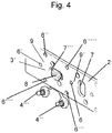
- the Dämmelements 3 ' has this on its back on a trained as a mushroom-shaped protuberance 8 male member 8, which can be performed by one of the receiving holes 7, 7', 7 ", 7"'and the respective receiving hole 7 "' then with a Retaining lip engages behind (see. Fig. 4 ), so that the insulating element 3 'is then pre-fixed to the wall bracket 2 by clamping.
- the insulating element 3 ' can be removed from the receiving hole 7''again and clamped in another, for example in the receiving hole 7, so that this clamping prefixing is reversible rotatably prefixed in the receiving hole 7 "'.
- two through-holes 9, 9 'of the insulating element 3 can be aligned such that they come to coincide with a pair of first bores 6, 6' of the wall mounting 2.
- the wall bracket 5 comprises a wall plate 10 with two through holes 11, 11 '. Through the through holes 11, 11 'are in the assembled state of the mounting system 1 according to the invention, the fastening elements 4 ", 4''out, which are then inserted into the first holes 6, 6' of the wall bracket 2 and thereby set the wall angle 5 to the wall bracket 2 , Next, the wall bracket 5 has a pipe connection portion 12 for connecting a pipe and a threaded opening 13 into which, for example, a faucet or the like can be screwed.
- the mounting system 1 For mounting the wall bracket 5 on a wall, the mounting system 1 according to the invention is taken at the site of its packaging. Then, the wall bracket 2 is first preferably secured by screws in the desired position on the wall.
- the insulating element 3 ' is pre-fixed to the wall bracket 2 in the delivery state of the mounting system 1 according to the invention by the plug-in element 8 designed as a mushroom-shaped protuberance 8 being inserted through the receiving hole 7 "of the wall bracket 2.
- the insulating element 3' is to be fitted in another receiving hole 7, 7 ' be inserted to take a different position on the wall mount 2, the insulating element 3 'is first removed from the receiving hole 7 "and pre-fixed by inserting the mushroom-shaped protuberance 8 in one of the other receiving holes 7, 7' on the wall bracket 2. Thereafter, the insulating element 3, if necessary, by turning aligned so that the through holes 9, 9 'of the Dämmelements 3 come with a pair of first holes 6, 6' of the wall bracket 2 to cover. Then the wall angle 5 is placed on the insulating element 3, that the through holes 11, 11 'of the wall angle 5 over the through holes 9, 9' of the Dämmelements 3 lie.
- the fastening elements 4 ", 4" 'designed as screws are torn off the insulating element and screwed into the through bores 11, 11' of the wall bracket 5 until the fastening elements 4 ", 4" 'are fixed in the first bores 6, 6' of the wall bracket 2 sit.
- the insulating element 3 is then arranged in an insulating manner between the wall bracket 2 and the wall bracket 5.
Landscapes
- Engineering & Computer Science (AREA)
- Health & Medical Sciences (AREA)
- Life Sciences & Earth Sciences (AREA)
- Hydrology & Water Resources (AREA)
- Public Health (AREA)
- Water Supply & Treatment (AREA)
- General Engineering & Computer Science (AREA)
- Mechanical Engineering (AREA)
- Connection Of Plates (AREA)
- Flanged Joints, Insulating Joints, And Other Joints (AREA)
- Supports For Pipes And Cables (AREA)
- Connector Housings Or Holding Contact Members (AREA)
Abstract
Description
- Die vorliegende Erfindung betrifft ein Montagesystem zur Befestigung eines Wandwinkels einer fluidführenden Installation an einer Wand, das eine Wandhalterung, die erste Bohrungen zur Aufnahme von Befestigungselementen aufweist; einen Wandwinkel, der Durchgangsbohrungen zur Durchführung der Befestigungselemente aufweist; ein Dämmelement zur Anordnung zwischen der Wandhalterung und dem Wandwinkel; und Befestigungselemente zur Befestigung des Wandwinkels an der Wandhalterung; umfasst.
- Derartige Montagesysteme zur Befestigung eines Wandwinkels einer fluidführenden Installation an einer Wand sind aus dem Stand der Technik durch offenkundige Vorbenutzung bekannt. Die Montagesysteme dienen bei Wasserinstallationen insbesondere dazu, Bauteile, wie Fittings, Gelenke und dergleichen, an einer Wand zu befestigen. Die Befestigung der Wandwinkel auf der Wandhalterung erfolgt in der Regel durch Befestigungselemente wie Schrauben. Zur Schallentkopplung dienen Dämmelemente, die zwischen dem Wandwinkel und der Wandhalterung sowie zwischen den Befestigungselementen und der Wandhalterung eingebracht werden. Am Markt sind derartige Montagesysteme, bei denen die anderen Komponenten der Wandhalterung lose beigelegt sind oder als separate Artikel von den Installationssystemherstellern angeboten werden. Für den Installateur auf der Baustelle hat dies jedoch den Nachteil, dass die einzelnen Komponenten vor Ort auf der Baustelle zusammengebaut werden müssen. Neben einem hohen Zeitaufwand für die Montage ist vor allem die Handhabung von einer Vielzahl an losen Komponenten unpraktisch für den Installateur. Darüber hinaus besteht die Gefahr, dass Einzelteile herunterfallen oder während des Transports oder insbesondere bei Kleinteilen bei der Installation verloren gehen.
- Dementsprechend liegt der vorliegenden Erfindung die Aufgabe zugrunde, ein Montagesystem zur Befestigung eines Wandwinkels einer fluidführenden Installation an einer Wand zur Verfügung zu stellen, das die Nachteile des Stands der Technik überwindet. Insbesondere soll bei dem erfindungsgemäßen Montagesystem die Gefahr, dass einzelne Komponenten verloren gehen reduziert sein. Darüber hinaus soll der Installateur die Montage unkompliziert vornehmen können.
- Diese und andere Aufgaben werden erfindungsgemäß durch ein Montagesystem mit den Merkmalen des Anspruchs 1 gelöst. Bevorzugte Ausführungsformen der vorliegenden Erfindung sind in den abhängigen Ansprüchen beschrieben.
- Erfindungsgemäß wurde erkannt, dass das Verlorengehen einzelner Komponenten, insbesondere des Dämmelements, des erfindungsgemäßen Montagesystems dadurch verhindert werden kann, dass das Dämmelement an der Wandhalterung vorfixiert ist. Erfindungsgemäß wird dies dadurch realisiert, dass das Dämmelement an seiner der Wandhalterung zugewandten Seite ein Einsteckelement aufweist. Das Einsteckelement ist klemmend in eines der Aufnahmelöcher in der Wandhalterung eingesetzt und wird so ausgeliefert. Auf der Baustelle befestigt der Installateur die Wandhalterung an der Wand, das Dämmelement befindet sich unmittelbar an der richtigen Stelle an der Wandhalterung, so dass der Installateur nur noch den Wandwinkel aufsetzen und diesen an der Wandhalterung befestigen muss. Ein langwieriges Suchen der einzelnen Komponenten entfällt durch das erfindungsgemäße Montagesystem. Dadurch ist die Montage eines Wandwinkels über einen Wandwinkel an der Wand erheblich vereinfacht.
- Dementsprechend liegt die vorliegende Erfindung in der Bereitstellung eines Montagesystems zur Befestigung eines Wandwinkels einer fluidführenden Installation an einer Wand, das eine Wandhalterung, die erste Bohrungen zur Aufnahme von Befestigungselementen aufweist; mindestens einen Wandwinkel, der Durchgangsbohrungen zur Durchführung der Befestigungselemente aufweist; mindestens ein Dämmelement zur Anordnung zwischen der Wandhalterung und dem Wandwinkel; und Befestigungselemente zur Befestigung der Wandhalterung an dem Wandwinkel; umfasst, wobei erfindungsgemäß die Wandhalterung weiter Aufnahmelöcher zur Vorfixierung des Dämmelements an Wandhalterung aufweist; und das Dämmelement mindestens ein Einsteckelement zur steckenden Vorfixierung an der Wandhalterung aufweist.
- Das Einsteckelement ist bevorzugt als Ausstülpung auf einer Seite des Dämmelements ausgebildet, wobei insbesondere eine pilzkopfförmige Ausstülpung mit Rückhaltelippe bevorzugt ist. Eine derartige Ausstülpung lässt sich besonders gut in den Aufnahmelöcher des Dämmelements verklemmen und trägt so zu einer guten Handhabbarkeit des erfindungsgemäßen Montagesystems bei.
In bevorzugten Ausführungsformen des erfindungsgemäßen Montagesystems ist die steckende Vorfixierung des Dämmelements an der Wandhalterung reversibel ausgestaltet. - Dadurch kann das Dämmelement im Bedarfsfall in unterschiedliche Aufnahmelöcher der Wandhalterung eingesetzt werden. Alternativ oder zusätzlich dazu kann es von Vorteil sein, wenn das Dämmelement mittels des Klemmelements in der Wandhalterung drehbar ist. Auf diese Weise ist eine Montage eines Wandwinkels in verschiedener Orientierung relativ zu einem Aufnahmeloch möglich.
- Als Materialien des Dämmelements bzw. der Dämmelemente sind thermoplastische Elastomere, insbesondere thermoplastische Elastomere auf Basis von Weich-PVC, PP/EPDM, EPDM sowie TPS, SBS und ASA (Acrylnitril-Styrol-Acrylester-Terpolymer), Elastomere wie Gummi oder Kautschuk, sowie Polyurethane, insbesondere geschäumte Polyurethane bevorzugt. Die Materialien des Dämmelements bzw. der Dämmelemente verfügen bevorzugt über eine Shore-Härte im Bereich von 50 Shore A bis 80 Shore A. Dabei sind elastisch verformbare Materialien mit einer Shore-Härte (Shore A) im Bereich von 60 Shore A bis 78 Shore A und insbesondere im Bereich von 65 Shore A bis 75 Shore A bevorzugt. Ein ganz besonders bevorzugtes Material besitzt eine Härte von etwa 70 Shore A (insbesondere im Bereich von 68 Shore A bis 72 Shore A). Die angegeben Werte der Shore-Härte beziehen sich dabei auf die Normen DIN ISO 7619, DIN 53505 und DIN 7868.
- Es kann auch nützlich sein, wenn die Befestigungselemente im Auslieferungszustand des Montagesystems mit dem Dämmelement verbunden sind. Damit hat der Installateur bei der Montage des erfindungsgemäßen Montagesystems die Befestigungselemente am Dämmelement erreichbar, wodurch die Montage noch stärker erleichtert wird. Darüber hinaus gehen die Befestigungselemente nicht so leicht verloren. Insbesondere sind die Befestigungselemente durch Kraftschluss mit Abschnitten des Dämmelements verbunden, die sich leicht vom Dämmelement abtrennen, insbesondere losreißen, lassen. Dadurch bleiben bei der Wandwinkelbefestigung die abgetrennten Abschnitte des Dämmelements an dem jeweiligen Befestigungselement vorhanden, so dass die Dämmeigenschaften auch zwischen den Befestigungselementen und dem Wandwinkel wirken.
- Das erfindungsgemäße Montagesystem sowie einzelne Bestandteile davon können auch zeilenweise oder schichtweise unter Verwendung eines zeilenaufbauenden oder schichtaufbauenden Fertigungsverfahrens (z. B. 3D-Druck) hergestellt werden.
Die vorliegende Erfindung wird im Folgenden unter Bezugnahme auf bevorzugte Ausführungsformen des erfindungsgemäßen Montagesystem im Detail erläutert, wobei die beigefügten Zeichnungen die Erfindung leichter verständlich machen sollen. Dabei versteht es sich, dass die dargestellte Ausführungsform die vorliegende Erfindung exemplarisch veranschaulichen und nicht einschränken soll. Es zeigen: - Figur 1
- eine perspektivische Darstellung eines Montagesystem zur Befestigung eines Wandwinkels gemäß einer Ausführungsform der vorliegenden Erfindung;
- Figur 2
- eine perspektivische Darstellung der Wandhalterung gemäß der in
Fig. 1 gezeigten Ausführungsform des erfindungsgemäßen Montagesystems; - Figur 3
- eine perspektivische Rückseitendarstellung eines Dämmelements gemäß der in
Fig. 1 gezeigten Ausführungsform des erfindungsgemäßen Montagesystems; und - Figur 4
- eine vergrößerte Darstellung eines rückseitigen Ausschnitts der Wandhalterung gemäß der in
Fig. 1 gezeigten Ausführungsform des erfindungsgemäßen Montagesystems mit eingesetztem Dämmeleement. - In
Figur 1 ist eine Ausführungsform des erfindungsgemäßen Montagesystems 1 zur Befestigung eines Wandwinkels einer fluidführenden Installation, beispielsweise eines Hausinstallationssystems oder eines Fußbodenheizungssystems, an einer Wand in einer perspektivischen Darstellung gezeigt. Das erfindungsgemäße Montagesystem 1 umfasst eine Wandhalterung 2; zwei Dämmelemente 3, 3' mit jeweils zwei als Schrauben ausgebildeten Befestigungselementen 4, 4', 4", 4''' sowie einen Wandwinkel 5. -
Figur 2 zeigt eine perspektivische Darstellung der Wandhalterung 2 des inFig. 1 dargestellten erfindungsgemäßen Montagesystems 1 mit den beiden Dämmelementen 3, 3'. In der dargestellten Ausführungsform handelt es sich bei der Wandhalterung 2 um ein längliches, gebogenes Metallblech. Die Wandhalterung 2 weist eine Vielzahl von ersten Bohrungen 6', 6", 6"', 6"", 6""'. Die ersten Bohrungen 6, 6', 6", 6"', 6"", 6""' sind vorzugsweise als Gewindebohrungen ausgebildet. Damit können als Schrauben ausgebildete Befestigungselemente mit der Wandhalterung 2 verschraubt werden. Auf diese Weise kann beispielsweise der Wandwinkel 5 an der Wandhalterung 2 des erfindungsgemäßen Montagesystems 1 befestigt werden und/oder die Wandhalterung kann an einer Wand festgelegt werden. Neben den ersten Bohrungen 6, 6', 6", 6"', 6"", 6""' verfügt die Wandhalterung 2 weiter über Aufnahmelöcher 7, 7', 7", 7"', mittels derer die Dämmelemente 3, 3' an der Wandhalterung 2 vorfixiert werden können. -
Figur 3 zeigt eine perspektivische Rückseitendarstellung des Dämmelements 3' des erfindungsgemäßen Montagesystems 1. Das Dämmelement 3' ist als Dämmkissen ausgebildet. Es besteht aus EPDM mit einer Shore-Härte von etwa 70 Shore A, wobei auch andere Materialien und/oder andere Shore-Härte verwendet werden können. Zur Vorfixierung des Dämmelements 3' verfügt dieses an seiner Rückseite über ein als pilzkopfförmige Ausstülpung 8 ausgebildetes Einsteckelement 8, das durch eines der Aufnahmelöcher 7, 7', 7", 7"' geführt werden kann und das betreffende Aufnahmeloch 7"' dann mit einer Rückhaltelippe hintergreift (vgl.Fig. 4 ), so dass das Dämmelement 3' dann an der Wandhalterung 2 klemmend vorfixiert ist. Das Dämmelement 3' kann aus dem Aufnahmeloch 7"' wieder entfernt werden und in ein anderes, beispielsweise in das Aufnahmeloch 7, eingeklemmt werden, so dass diese klemmende Vorfixierung reversibel ausgeführt ist. Aufgrund der im Wesentlichen kreisrunden Geometrie der Ausstülpung 8 ist das Dämmelement 3' in dem Aufnahmeloch 7"' drehbar vorfixiert. Dadurch können zwei Durchgangslöcher 9, 9' des Dämmelements 3 derart ausgerichtet werden, dass diese mit einem Paar erster Bohrungen 6, 6' der Wandhalterung 2 zur Deckung kommen. Über dünne Stege des Dämmelements 3' sind zwei Befestigungselemente 4", 4"' mit dem Dämmelement 3' verbunden. Im Bedarfsfall kann der Installateur die Befestigungselemente 4", 4"' von dem Dämmelement 3 abreißen. Dabei bleiben Abschnitte des Dämmelements 3' mit dem jeweiligen Befestigungselement 4", 4"' verbunden. Diese Abschnitte des Dämmelements 3' fungieren nach der Befestigung des Wandwinkels 5 an der Wandhalterung 2 als Dämmung zwischen dem Wandwinkel 5 und dem jeweiligen Befestigungselement 4", 4"', wobei das Dämmelement 3' zwischen dem Wandwinkel 5 und der Wandhalterung 2 angeordnet ist. - Der Wandwinkel 5 umfasst eine Wandscheibe 10 mit zwei Durchgangsbohrungen 11, 11'. Durch die Durchgangsbohrungen 11, 11' sind im montierten Zustand des erfindungsgemäßen Montagesystems 1 die Befestigungselemente 4", 4"' geführt, die dann in die ersten Bohrungen 6, 6' der Wandhalterung 2 eingeführt sind und dadurch den Wandwinkel 5 an der Wandhalterung 2 festlegen. Weiter weist der Wandwinkel 5 einen Rohrverbindungsabschnitt 12 zum Anschluss einer Rohrleitung sowie eine Gewindeöffnung 13 auf, in die beispielsweise ein Wasserhahn oder ähnliches eingeschraubt werden kann.
- Zur Montage des Wandhalters 5 an einer Wand wird das erfindungsgemäße Montagesystem 1 an der Baustelle seiner Verpackung entnommen. Daraufhin wird die Wandhalterung 2 zunächst vorzugsweise mittels Schrauben in der gewünschten Position an der Wand befestigt. Das Dämmelement 3' ist im Auslieferungszustand des erfindungsgemäßen Montagesystems 1 an der Wandhalterung 2 vorfixiert, indem das als pilzkopfförmige Ausstülpung 8 ausgebildete Einsteckelement 8 durch das Aufnahmeloch 7" der Wandhalterung 2 gesteckt ist. Soll das Dämmelement 3' in ein anderes Aufnahmeloch 7, 7' eingesteckt werden, um eine andere Position auf der Wandhalterung 2 einzunehmen, wird das Dämmelement 3' zunächst aus dem Aufnahmeloch 7" entnommen und durch Einstecken der pilzkopfförmigen Ausstülpung 8 in eines der anderen Aufnahmelöcher 7, 7' an der Wandhalterung 2 vorfixiert. Danach kann das Dämmelement 3 im Bedarfsfall durch Drehen derart ausgerichtet, dass die Durchgangslöcher 9, 9' des Dämmelements 3 mit einem Paar erster Bohrungen 6, 6' der Wandhalterung 2 zur Deckung kommen. Dann wird der Wandwinkel 5 so auf das Dämmelement 3 aufgesetzt, dass die Durchgangsbohrungen 11, 11' des Wandwinkels 5 über den Durchgangslöchern 9, 9' des Dämmelements 3 liegen. Daraufhin werden die als Schrauben ausgebildeten Befestigungselemente 4", 4"' von dem Dämmelement abgerissen und in die Durchgangsbohrungen 11, 11' des Wandwinkels 5 eingedreht, bis die Befestigungselemente 4", 4"' fest in den ersten Bohrungen 6, 6' der Wandhalterung 2 sitzen. Das Dämmelement 3 ist dann dämmend zwischen der Wandhalterung 2 und dem Wandwinkel 5 angeordnet.
- Die vorliegende Erfindung wurde exemplarisch unter Bezugnahme auf die in den Figuren gezeigte Ausführungsform des erfindungsgemäßen Montagesystems im Detail erläutert. Es versteht sich, dass die vorliegende Erfindung nicht auf die gezeigte Ausführungsform beschränkt ist, sondern sich der Umfang der vorliegenden Erfindung aus den beigefügten Ansprüchen ergibt.
Claims (7)
- Montagesystem (1) zur Befestigung eines Wandwinkels (5) einer fluidführenden Installation an einer Wand, umfassend:eine Wandhalterung (2), die erste Bohrungen (6, 6', 6", 6"', 6"", 6""') zur Aufnahme von Befestigungselementen (4, 4', 4", 4"') aufweist;mindestens einen Wandwinkel (5), der Durchgangsbohrungen (11, 11') zur Durchführung der Befestigungselemente (4, 4', 4", 4"') aufweist;mindestens ein Dämmelement (3, 3') zur Anordnung zwischen der Wandhalterung (2) und dem Wandwinkel (5);Befestigungselemente (4, 4', 4", 4"') zur Befestigung des Wandwinkels (5) an der Wandhalterung (2);dadurch gekennzeichnet, dassdie Wandhalterung (2) weiter Aufnahmelöcher (7, 7', 7", 7"') zur Vorfixierung des Dämmelements (3, 3') an der Wandhalterung (2) aufweist; unddas Dämmelement (3, 3') mindestens ein Einsteckelement (8) zur steckenden Vorfixierung an der Wandhalterung (2) aufweist.
- Montagesystem (1) nach Anspruch 1, dadurch gekennzeichnet, dass das Einsteckelement (8) als eine Ausstülpung (8) auf einer Seite des Dämmelements (3, 3') ausgebildet ist.
- Montagesystem (1) nach Anspruch 2, dadurch gekennzeichnet, dass die Ausstülpung (8) auf einer Seite des Dämmelements (3, 3') pilzkopfförmig mit Rückhaltelippe ausgebildet ist.
- Montagesystem (1) nach einem der Ansprüche 1 bis 3, dadurch gekennzeichnet, dass die steckende Vorfixierung des Dämmelements (3, 3') an der Wandhalterung (2) reversibel ausgestaltet ist.
- Montagesystem (1) nach einem der Ansprüche 1 bis 4, dadurch gekennzeichnet, dass das Dämmelement (3, 3') mittels des Einsteckelements (8) in der Wandhalterung (2) drehbar ist.
- Montagesystem (1) nach einem der Ansprüche 1 bis 5, dadurch gekennzeichnet, dass die Befestigungselemente (4, 4', 4", 4"') im Auslieferungszustand des Montagesystems (1) mit dem Dämmelement (3, 3') verbunden sind.
- Montagesystem (1) nach Anspruch 6, dadurch gekennzeichnet, dass die Befestigungselemente (4, 4', 4", 4"') unter Abtrennung eines Abschnitts des Dämmelements (3, 3') vom Dämmelement (3, 3') abtrennbar sind.
Applications Claiming Priority (1)
| Application Number | Priority Date | Filing Date | Title |
|---|---|---|---|
| DE202016107269.7U DE202016107269U1 (de) | 2016-12-22 | 2016-12-22 | Montagesystem zur Befestigung eines Wandwinkels einer fluidführenden Installation an einer Wand |
Publications (2)
| Publication Number | Publication Date |
|---|---|
| EP3339712A1 true EP3339712A1 (de) | 2018-06-27 |
| EP3339712B1 EP3339712B1 (de) | 2019-07-17 |
Family
ID=60661763
Family Applications (1)
| Application Number | Title | Priority Date | Filing Date |
|---|---|---|---|
| EP17205409.0A Active EP3339712B1 (de) | 2016-12-22 | 2017-12-05 | Montagesystem zur befestigung eines wandwinkels einer fluidführenden installation an einer wand |
Country Status (3)
| Country | Link |
|---|---|
| EP (1) | EP3339712B1 (de) |
| DE (1) | DE202016107269U1 (de) |
| RU (1) | RU2750739C2 (de) |
Cited By (2)
| Publication number | Priority date | Publication date | Assignee | Title |
|---|---|---|---|---|
| EP3757303A1 (de) * | 2019-06-26 | 2020-12-30 | Geberit International AG | Sanitärinstallationssystem |
| CN113586805A (zh) * | 2021-07-21 | 2021-11-02 | 深圳市金世纪工程实业有限公司 | 一种保护市政管线的施工工艺 |
Families Citing this family (2)
| Publication number | Priority date | Publication date | Assignee | Title |
|---|---|---|---|---|
| DE102023124954A1 (de) * | 2023-09-15 | 2025-03-20 | Vaillant Gmbh | Befestigungsanordnung mit einem Gas-Absperrventil |
| DE102023124947A1 (de) * | 2023-09-15 | 2025-03-20 | Vaillant Gmbh | Befestigungsanordnung, umfassend ein Fixierblech und ein Gas-Absperrventil |
Citations (4)
| Publication number | Priority date | Publication date | Assignee | Title |
|---|---|---|---|---|
| EP0660019A1 (de) * | 1993-12-27 | 1995-06-28 | KE-KELIT Kunststoffwerk Gesellschaft m.b.H. | Befestigungsvorrichtung für mit wenigstens zwei Befestigungslöchern versehene Rohrleitungs-Formstücke aus Kunststoff an gelochten Blechträgern |
| DE4406574C1 (de) * | 1994-03-01 | 1995-12-21 | Rasmussen Gmbh | Rohrschelle |
| EP0908566A1 (de) * | 1997-10-13 | 1999-04-14 | Fischerwerke Arthur Fischer GmbH & Co. KG | Wandscheibe für Sanitärinstallationen |
| DE202010016881U1 (de) * | 2010-12-21 | 2012-03-22 | Uponor Innovation Ab | Vielzweckbefestigungselement mit einem Leitungswinkel |
Family Cites Families (7)
| Publication number | Priority date | Publication date | Assignee | Title |
|---|---|---|---|---|
| US4314687A (en) * | 1980-05-09 | 1982-02-09 | The Logsdon Foundation | Sound isolating device for suspending plumbing pipes |
| DE4345103C2 (de) * | 1993-02-01 | 1996-09-05 | Mannesmann Ag | Vorrichtung zur Befestigung von winkeligen Installationselementen |
| DE19507845C1 (de) * | 1995-03-07 | 1996-07-04 | Mero Werke Kg | Vorrichtung zur Sicherung einer einen Träger durchgreifenden und an diesem unter Zwischenlage von schallisolierenden Elementen kraftschlüssig befestigbaren Rohrmuffe oder dergleichen |
| EP1510625B1 (de) * | 2003-08-20 | 2006-07-05 | Geberit Technik Ag | Befestigungsvorrichtung für die Wandmontage von sanitären Elementen |
| DE20319806U1 (de) * | 2003-12-20 | 2004-04-08 | Kessler, Peter | Montageschiene |
| DE202009007862U1 (de) * | 2009-05-28 | 2009-09-17 | Scherer, Norbert | Universalanschlussfitting |
| RU129122U1 (ru) * | 2012-12-07 | 2013-06-20 | Михаил Юрьевич Кузьменков | Устройство для монтажа санитарно-технической арматуры |
-
2016
- 2016-12-22 DE DE202016107269.7U patent/DE202016107269U1/de not_active Expired - Lifetime
-
2017
- 2017-12-05 EP EP17205409.0A patent/EP3339712B1/de active Active
- 2017-12-21 RU RU2017145013A patent/RU2750739C2/ru active
Patent Citations (4)
| Publication number | Priority date | Publication date | Assignee | Title |
|---|---|---|---|---|
| EP0660019A1 (de) * | 1993-12-27 | 1995-06-28 | KE-KELIT Kunststoffwerk Gesellschaft m.b.H. | Befestigungsvorrichtung für mit wenigstens zwei Befestigungslöchern versehene Rohrleitungs-Formstücke aus Kunststoff an gelochten Blechträgern |
| DE4406574C1 (de) * | 1994-03-01 | 1995-12-21 | Rasmussen Gmbh | Rohrschelle |
| EP0908566A1 (de) * | 1997-10-13 | 1999-04-14 | Fischerwerke Arthur Fischer GmbH & Co. KG | Wandscheibe für Sanitärinstallationen |
| DE202010016881U1 (de) * | 2010-12-21 | 2012-03-22 | Uponor Innovation Ab | Vielzweckbefestigungselement mit einem Leitungswinkel |
Cited By (3)
| Publication number | Priority date | Publication date | Assignee | Title |
|---|---|---|---|---|
| EP3757303A1 (de) * | 2019-06-26 | 2020-12-30 | Geberit International AG | Sanitärinstallationssystem |
| CN113586805A (zh) * | 2021-07-21 | 2021-11-02 | 深圳市金世纪工程实业有限公司 | 一种保护市政管线的施工工艺 |
| CN113586805B (zh) * | 2021-07-21 | 2023-09-15 | 深圳市金世纪工程实业有限公司 | 一种保护市政管线的施工工艺 |
Also Published As
| Publication number | Publication date |
|---|---|
| RU2750739C2 (ru) | 2021-07-02 |
| RU2017145013A3 (de) | 2021-03-10 |
| DE202016107269U1 (de) | 2018-03-23 |
| RU2017145013A (ru) | 2019-06-24 |
| EP3339712B1 (de) | 2019-07-17 |
Similar Documents
| Publication | Publication Date | Title |
|---|---|---|
| EP3339712B1 (de) | Montagesystem zur befestigung eines wandwinkels einer fluidführenden installation an einer wand | |
| DE60305554T2 (de) | Anordnung, Verfahren und Vorrichtung für Montage und Anschluss einer sanitären Installationsleitung | |
| DE202009015554U1 (de) | Rohrschelle | |
| DE29614352U1 (de) | Montagebaustein für die Sanitärinstallation | |
| DE102013110966A1 (de) | Befestiger für ein wandhängendes Objekt | |
| DE102009008684B4 (de) | Befestigungselement, Vorrichtung sowie Verfahren zum Befestigen eines flexiblen Rohres | |
| DE102012024122A1 (de) | Haltesystem zum Halten und Positionieren von langen Gegenständen, wie Schläuchen, Rohren, Kabeln, und dergleichen | |
| EP2674681B1 (de) | Wandhalterung für Installationselemente, insbesondere für Heizkreisverteiler, Installationselement zur Aufnahme in einer derartigen Wandhalterung, Installationselement-Montagesystem sowie Verfahren zur Montage eines Installationselements an einer Wand oder einer Tragstruktur | |
| DE202018004778U1 (de) | Schelle zum Klemmen einer rohrförmigen Leitung an eine Führungsschiene | |
| DE202017105636U1 (de) | Bügelschelle | |
| EP2639904A1 (de) | Geräteeinbaukanal und Verfahren zur Wandmontage eines Geräteeinbaukanals | |
| DE202006007690U1 (de) | Zaun aus Zaunpfosten und Gittermatten | |
| EP3312518B1 (de) | Fluidverteiler-montageanordnung | |
| DE102013112005A1 (de) | Befestiger für ein wandhängendes Objekt | |
| EP3140174A1 (de) | Fahrzeug, insbesondere schienenfahrzeug, mit einer montageschiene | |
| DE29612197U1 (de) | Montagebaustein für die Sanitärinstallation | |
| DE19756208A1 (de) | Vorrichtung zur Befestigung einer Verbindungsrohrleitung zu einem Wasserstop an einem elektrischen Haushaltsgerät | |
| EP2468965B1 (de) | Vielzweckbefestigungselement mit einem Leitungsanschlusswinkel | |
| EP3394491B1 (de) | Installationselement-montagesystem | |
| DE102017129915A1 (de) | Fluidverteiler-Montageanordnung | |
| EP1731812B1 (de) | Kabelbefestigungsklemme zur erleichterten Befestigung, Öffnung und Schließung | |
| DE102009040131B3 (de) | Befestigungslasche für ein Schutzzaunfeld | |
| DE102013012596A1 (de) | Vorrichtung zum Durchführen von Kabeln | |
| DE102012012356A1 (de) | Verfahren zum Anbringen einer Abdeckung an einem Bauelement, sowie ein Konstruktionselement | |
| DE102012210835A1 (de) | Rohrbefestigungselement, System zur Rohrbefestigung und Verfahren zur Befestigung eines Rohres |
Legal Events
| Date | Code | Title | Description |
|---|---|---|---|
| PUAI | Public reference made under article 153(3) epc to a published international application that has entered the european phase |
Free format text: ORIGINAL CODE: 0009012 |
|
| STAA | Information on the status of an ep patent application or granted ep patent |
Free format text: STATUS: THE APPLICATION HAS BEEN PUBLISHED |
|
| AK | Designated contracting states |
Kind code of ref document: A1 Designated state(s): AL AT BE BG CH CY CZ DE DK EE ES FI FR GB GR HR HU IE IS IT LI LT LU LV MC MK MT NL NO PL PT RO RS SE SI SK SM TR |
|
| AX | Request for extension of the european patent |
Extension state: BA ME |
|
| STAA | Information on the status of an ep patent application or granted ep patent |
Free format text: STATUS: REQUEST FOR EXAMINATION WAS MADE |
|
| 17P | Request for examination filed |
Effective date: 20181220 |
|
| RBV | Designated contracting states (corrected) |
Designated state(s): AL AT BE BG CH CY CZ DE DK EE ES FI FR GB GR HR HU IE IS IT LI LT LU LV MC MK MT NL NO PL PT RO RS SE SI SK SM TR |
|
| GRAP | Despatch of communication of intention to grant a patent |
Free format text: ORIGINAL CODE: EPIDOSNIGR1 |
|
| STAA | Information on the status of an ep patent application or granted ep patent |
Free format text: STATUS: GRANT OF PATENT IS INTENDED |
|
| RIC1 | Information provided on ipc code assigned before grant |
Ipc: F16L 55/035 20060101AFI20190122BHEP Ipc: E03C 1/02 20060101ALI20190122BHEP |
|
| INTG | Intention to grant announced |
Effective date: 20190208 |
|
| GRAS | Grant fee paid |
Free format text: ORIGINAL CODE: EPIDOSNIGR3 |
|
| GRAA | (expected) grant |
Free format text: ORIGINAL CODE: 0009210 |
|
| STAA | Information on the status of an ep patent application or granted ep patent |
Free format text: STATUS: THE PATENT HAS BEEN GRANTED |
|
| AK | Designated contracting states |
Kind code of ref document: B1 Designated state(s): AL AT BE BG CH CY CZ DE DK EE ES FI FR GB GR HR HU IE IS IT LI LT LU LV MC MK MT NL NO PL PT RO RS SE SI SK SM TR |
|
| REG | Reference to a national code |
Ref country code: GB Ref legal event code: FG4D Free format text: NOT ENGLISH |
|
| REG | Reference to a national code |
Ref country code: CH Ref legal event code: EP |
|
| REG | Reference to a national code |
Ref country code: IE Ref legal event code: FG4D Free format text: LANGUAGE OF EP DOCUMENT: GERMAN |
|
| REG | Reference to a national code |
Ref country code: DE Ref legal event code: R096 Ref document number: 502017001788 Country of ref document: DE |
|
| REG | Reference to a national code |
Ref country code: AT Ref legal event code: REF Ref document number: 1156171 Country of ref document: AT Kind code of ref document: T Effective date: 20190815 |
|
| REG | Reference to a national code |
Ref country code: NL Ref legal event code: MP Effective date: 20190717 |
|
| REG | Reference to a national code |
Ref country code: LT Ref legal event code: MG4D |
|
| PG25 | Lapsed in a contracting state [announced via postgrant information from national office to epo] |
Ref country code: FI Free format text: LAPSE BECAUSE OF FAILURE TO SUBMIT A TRANSLATION OF THE DESCRIPTION OR TO PAY THE FEE WITHIN THE PRESCRIBED TIME-LIMIT Effective date: 20190717 Ref country code: BG Free format text: LAPSE BECAUSE OF FAILURE TO SUBMIT A TRANSLATION OF THE DESCRIPTION OR TO PAY THE FEE WITHIN THE PRESCRIBED TIME-LIMIT Effective date: 20191017 Ref country code: SE Free format text: LAPSE BECAUSE OF FAILURE TO SUBMIT A TRANSLATION OF THE DESCRIPTION OR TO PAY THE FEE WITHIN THE PRESCRIBED TIME-LIMIT Effective date: 20190717 Ref country code: NL Free format text: LAPSE BECAUSE OF FAILURE TO SUBMIT A TRANSLATION OF THE DESCRIPTION OR TO PAY THE FEE WITHIN THE PRESCRIBED TIME-LIMIT Effective date: 20190717 Ref country code: NO Free format text: LAPSE BECAUSE OF FAILURE TO SUBMIT A TRANSLATION OF THE DESCRIPTION OR TO PAY THE FEE WITHIN THE PRESCRIBED TIME-LIMIT Effective date: 20191017 Ref country code: HR Free format text: LAPSE BECAUSE OF FAILURE TO SUBMIT A TRANSLATION OF THE DESCRIPTION OR TO PAY THE FEE WITHIN THE PRESCRIBED TIME-LIMIT Effective date: 20190717 Ref country code: PT Free format text: LAPSE BECAUSE OF FAILURE TO SUBMIT A TRANSLATION OF THE DESCRIPTION OR TO PAY THE FEE WITHIN THE PRESCRIBED TIME-LIMIT Effective date: 20191118 Ref country code: LT Free format text: LAPSE BECAUSE OF FAILURE TO SUBMIT A TRANSLATION OF THE DESCRIPTION OR TO PAY THE FEE WITHIN THE PRESCRIBED TIME-LIMIT Effective date: 20190717 |
|
| PG25 | Lapsed in a contracting state [announced via postgrant information from national office to epo] |
Ref country code: LV Free format text: LAPSE BECAUSE OF FAILURE TO SUBMIT A TRANSLATION OF THE DESCRIPTION OR TO PAY THE FEE WITHIN THE PRESCRIBED TIME-LIMIT Effective date: 20190717 Ref country code: AL Free format text: LAPSE BECAUSE OF FAILURE TO SUBMIT A TRANSLATION OF THE DESCRIPTION OR TO PAY THE FEE WITHIN THE PRESCRIBED TIME-LIMIT Effective date: 20190717 Ref country code: GR Free format text: LAPSE BECAUSE OF FAILURE TO SUBMIT A TRANSLATION OF THE DESCRIPTION OR TO PAY THE FEE WITHIN THE PRESCRIBED TIME-LIMIT Effective date: 20191018 Ref country code: ES Free format text: LAPSE BECAUSE OF FAILURE TO SUBMIT A TRANSLATION OF THE DESCRIPTION OR TO PAY THE FEE WITHIN THE PRESCRIBED TIME-LIMIT Effective date: 20190717 Ref country code: RS Free format text: LAPSE BECAUSE OF FAILURE TO SUBMIT A TRANSLATION OF THE DESCRIPTION OR TO PAY THE FEE WITHIN THE PRESCRIBED TIME-LIMIT Effective date: 20190717 Ref country code: IS Free format text: LAPSE BECAUSE OF FAILURE TO SUBMIT A TRANSLATION OF THE DESCRIPTION OR TO PAY THE FEE WITHIN THE PRESCRIBED TIME-LIMIT Effective date: 20191117 |
|
| PG25 | Lapsed in a contracting state [announced via postgrant information from national office to epo] |
Ref country code: TR Free format text: LAPSE BECAUSE OF FAILURE TO SUBMIT A TRANSLATION OF THE DESCRIPTION OR TO PAY THE FEE WITHIN THE PRESCRIBED TIME-LIMIT Effective date: 20190717 |
|
| PG25 | Lapsed in a contracting state [announced via postgrant information from national office to epo] |
Ref country code: RO Free format text: LAPSE BECAUSE OF FAILURE TO SUBMIT A TRANSLATION OF THE DESCRIPTION OR TO PAY THE FEE WITHIN THE PRESCRIBED TIME-LIMIT Effective date: 20190717 Ref country code: PL Free format text: LAPSE BECAUSE OF FAILURE TO SUBMIT A TRANSLATION OF THE DESCRIPTION OR TO PAY THE FEE WITHIN THE PRESCRIBED TIME-LIMIT Effective date: 20190717 Ref country code: DK Free format text: LAPSE BECAUSE OF FAILURE TO SUBMIT A TRANSLATION OF THE DESCRIPTION OR TO PAY THE FEE WITHIN THE PRESCRIBED TIME-LIMIT Effective date: 20190717 Ref country code: EE Free format text: LAPSE BECAUSE OF FAILURE TO SUBMIT A TRANSLATION OF THE DESCRIPTION OR TO PAY THE FEE WITHIN THE PRESCRIBED TIME-LIMIT Effective date: 20190717 |
|
| PG25 | Lapsed in a contracting state [announced via postgrant information from national office to epo] |
Ref country code: SM Free format text: LAPSE BECAUSE OF FAILURE TO SUBMIT A TRANSLATION OF THE DESCRIPTION OR TO PAY THE FEE WITHIN THE PRESCRIBED TIME-LIMIT Effective date: 20190717 Ref country code: IS Free format text: LAPSE BECAUSE OF FAILURE TO SUBMIT A TRANSLATION OF THE DESCRIPTION OR TO PAY THE FEE WITHIN THE PRESCRIBED TIME-LIMIT Effective date: 20200224 Ref country code: CZ Free format text: LAPSE BECAUSE OF FAILURE TO SUBMIT A TRANSLATION OF THE DESCRIPTION OR TO PAY THE FEE WITHIN THE PRESCRIBED TIME-LIMIT Effective date: 20190717 Ref country code: SK Free format text: LAPSE BECAUSE OF FAILURE TO SUBMIT A TRANSLATION OF THE DESCRIPTION OR TO PAY THE FEE WITHIN THE PRESCRIBED TIME-LIMIT Effective date: 20190717 |
|
| REG | Reference to a national code |
Ref country code: DE Ref legal event code: R097 Ref document number: 502017001788 Country of ref document: DE |
|
| PLBE | No opposition filed within time limit |
Free format text: ORIGINAL CODE: 0009261 |
|
| STAA | Information on the status of an ep patent application or granted ep patent |
Free format text: STATUS: NO OPPOSITION FILED WITHIN TIME LIMIT |
|
| PG2D | Information on lapse in contracting state deleted |
Ref country code: IS |
|
| 26N | No opposition filed |
Effective date: 20200603 |
|
| REG | Reference to a national code |
Ref country code: BE Ref legal event code: MM Effective date: 20191231 |
|
| PG25 | Lapsed in a contracting state [announced via postgrant information from national office to epo] |
Ref country code: MC Free format text: LAPSE BECAUSE OF FAILURE TO SUBMIT A TRANSLATION OF THE DESCRIPTION OR TO PAY THE FEE WITHIN THE PRESCRIBED TIME-LIMIT Effective date: 20190717 Ref country code: SI Free format text: LAPSE BECAUSE OF FAILURE TO SUBMIT A TRANSLATION OF THE DESCRIPTION OR TO PAY THE FEE WITHIN THE PRESCRIBED TIME-LIMIT Effective date: 20190717 |
|
| PG25 | Lapsed in a contracting state [announced via postgrant information from national office to epo] |
Ref country code: IE Free format text: LAPSE BECAUSE OF NON-PAYMENT OF DUE FEES Effective date: 20191205 Ref country code: LU Free format text: LAPSE BECAUSE OF NON-PAYMENT OF DUE FEES Effective date: 20191205 |
|
| PG25 | Lapsed in a contracting state [announced via postgrant information from national office to epo] |
Ref country code: BE Free format text: LAPSE BECAUSE OF NON-PAYMENT OF DUE FEES Effective date: 20191231 |
|
| PG25 | Lapsed in a contracting state [announced via postgrant information from national office to epo] |
Ref country code: CY Free format text: LAPSE BECAUSE OF FAILURE TO SUBMIT A TRANSLATION OF THE DESCRIPTION OR TO PAY THE FEE WITHIN THE PRESCRIBED TIME-LIMIT Effective date: 20190717 |
|
| PG25 | Lapsed in a contracting state [announced via postgrant information from national office to epo] |
Ref country code: MT Free format text: LAPSE BECAUSE OF FAILURE TO SUBMIT A TRANSLATION OF THE DESCRIPTION OR TO PAY THE FEE WITHIN THE PRESCRIBED TIME-LIMIT Effective date: 20190717 Ref country code: HU Free format text: LAPSE BECAUSE OF FAILURE TO SUBMIT A TRANSLATION OF THE DESCRIPTION OR TO PAY THE FEE WITHIN THE PRESCRIBED TIME-LIMIT; INVALID AB INITIO Effective date: 20171205 |
|
| REG | Reference to a national code |
Ref country code: CH Ref legal event code: PL |
|
| PG25 | Lapsed in a contracting state [announced via postgrant information from national office to epo] |
Ref country code: LI Free format text: LAPSE BECAUSE OF NON-PAYMENT OF DUE FEES Effective date: 20201231 Ref country code: CH Free format text: LAPSE BECAUSE OF NON-PAYMENT OF DUE FEES Effective date: 20201231 |
|
| REG | Reference to a national code |
Ref country code: DE Ref legal event code: R081 Ref document number: 502017001788 Country of ref document: DE Owner name: REHAU INDUSTRIES SE & CO. KG, DE Free format text: FORMER OWNER: REHAU AG + CO, 95111 REHAU, DE |
|
| REG | Reference to a national code |
Ref country code: GB Ref legal event code: 732E Free format text: REGISTERED BETWEEN 20220505 AND 20220512 |
|
| REG | Reference to a national code |
Ref country code: AT Ref legal event code: PC Ref document number: 1156171 Country of ref document: AT Kind code of ref document: T Owner name: REHAU INDUSTRIES SE & CO. KG, DE Effective date: 20220419 |
|
| PG25 | Lapsed in a contracting state [announced via postgrant information from national office to epo] |
Ref country code: MK Free format text: LAPSE BECAUSE OF FAILURE TO SUBMIT A TRANSLATION OF THE DESCRIPTION OR TO PAY THE FEE WITHIN THE PRESCRIBED TIME-LIMIT Effective date: 20190717 |
|
| PGFP | Annual fee paid to national office [announced via postgrant information from national office to epo] |
Ref country code: GB Payment date: 20251111 Year of fee payment: 9 |
|
| PGFP | Annual fee paid to national office [announced via postgrant information from national office to epo] |
Ref country code: AT Payment date: 20251120 Year of fee payment: 9 |
|
| PGFP | Annual fee paid to national office [announced via postgrant information from national office to epo] |
Ref country code: IT Payment date: 20251230 Year of fee payment: 9 |
|
| PGFP | Annual fee paid to national office [announced via postgrant information from national office to epo] |
Ref country code: FR Payment date: 20251125 Year of fee payment: 9 |
|
| PGFP | Annual fee paid to national office [announced via postgrant information from national office to epo] |
Ref country code: DE Payment date: 20251231 Year of fee payment: 9 |