EP3335042B1 - Bio/chemical assay devices and methods for simplified steps, small samples, accelerated speed, and ease-of-use - Google Patents
Bio/chemical assay devices and methods for simplified steps, small samples, accelerated speed, and ease-of-use Download PDFInfo
- Publication number
- EP3335042B1 EP3335042B1 EP16835870.3A EP16835870A EP3335042B1 EP 3335042 B1 EP3335042 B1 EP 3335042B1 EP 16835870 A EP16835870 A EP 16835870A EP 3335042 B1 EP3335042 B1 EP 3335042B1
- Authority
- EP
- European Patent Office
- Prior art keywords
- sample
- plates
- plate
- spacers
- thickness
- Prior art date
- Legal status (The legal status is an assumption and is not a legal conclusion. Google has not performed a legal analysis and makes no representation as to the accuracy of the status listed.)
- Active
Links
Images


Classifications
-
- G—PHYSICS
- G01—MEASURING; TESTING
- G01N—INVESTIGATING OR ANALYSING MATERIALS BY DETERMINING THEIR CHEMICAL OR PHYSICAL PROPERTIES
- G01N33/00—Investigating or analysing materials by specific methods not covered by groups G01N1/00 - G01N31/00
- G01N33/48—Biological material, e.g. blood, urine; Haemocytometers
- G01N33/483—Physical analysis of biological material
-
- B—PERFORMING OPERATIONS; TRANSPORTING
- B01—PHYSICAL OR CHEMICAL PROCESSES OR APPARATUS IN GENERAL
- B01L—CHEMICAL OR PHYSICAL LABORATORY APPARATUS FOR GENERAL USE
- B01L3/00—Containers or dishes for laboratory use, e.g. laboratory glassware; Droppers
- B01L3/50—Containers for the purpose of retaining a material to be analysed, e.g. test tubes
- B01L3/505—Containers for the purpose of retaining a material to be analysed, e.g. test tubes flexible containers not provided for above
- B01L3/5055—Hinged, e.g. opposable surfaces
-
- G—PHYSICS
- G01—MEASURING; TESTING
- G01N—INVESTIGATING OR ANALYSING MATERIALS BY DETERMINING THEIR CHEMICAL OR PHYSICAL PROPERTIES
- G01N1/00—Sampling; Preparing specimens for investigation
- G01N1/28—Preparing specimens for investigation including physical details of (bio-)chemical methods covered elsewhere, e.g. G01N33/50, C12Q
- G01N1/2813—Producing thin layers of samples on a substrate, e.g. smearing, spinning-on
-
- G—PHYSICS
- G01—MEASURING; TESTING
- G01N—INVESTIGATING OR ANALYSING MATERIALS BY DETERMINING THEIR CHEMICAL OR PHYSICAL PROPERTIES
- G01N1/00—Sampling; Preparing specimens for investigation
- G01N1/28—Preparing specimens for investigation including physical details of (bio-)chemical methods covered elsewhere, e.g. G01N33/50, C12Q
- G01N1/30—Staining; Impregnating ; Fixation; Dehydration; Multistep processes for preparing samples of tissue, cell or nucleic acid material and the like for analysis
-
- G—PHYSICS
- G01—MEASURING; TESTING
- G01N—INVESTIGATING OR ANALYSING MATERIALS BY DETERMINING THEIR CHEMICAL OR PHYSICAL PROPERTIES
- G01N15/00—Investigating characteristics of particles; Investigating permeability, pore-volume or surface-area of porous materials
- G01N15/10—Investigating individual particles
- G01N15/14—Optical investigation techniques, e.g. flow cytometry
- G01N15/1484—Optical investigation techniques, e.g. flow cytometry microstructural devices
-
- G—PHYSICS
- G01—MEASURING; TESTING
- G01N—INVESTIGATING OR ANALYSING MATERIALS BY DETERMINING THEIR CHEMICAL OR PHYSICAL PROPERTIES
- G01N21/00—Investigating or analysing materials by the use of optical means, i.e. using sub-millimetre waves, infrared, visible or ultraviolet light
- G01N21/62—Systems in which the material investigated is excited whereby it emits light or causes a change in wavelength of the incident light
- G01N21/63—Systems in which the material investigated is excited whereby it emits light or causes a change in wavelength of the incident light optically excited
- G01N21/64—Fluorescence; Phosphorescence
- G01N21/645—Specially adapted constructive features of fluorimeters
- G01N21/6452—Individual samples arranged in a regular 2D-array, e.g. multiwell plates
-
- G—PHYSICS
- G01—MEASURING; TESTING
- G01N—INVESTIGATING OR ANALYSING MATERIALS BY DETERMINING THEIR CHEMICAL OR PHYSICAL PROPERTIES
- G01N21/00—Investigating or analysing materials by the use of optical means, i.e. using sub-millimetre waves, infrared, visible or ultraviolet light
- G01N21/62—Systems in which the material investigated is excited whereby it emits light or causes a change in wavelength of the incident light
- G01N21/66—Systems in which the material investigated is excited whereby it emits light or causes a change in wavelength of the incident light electrically excited, e.g. electroluminescence
- G01N21/69—Systems in which the material investigated is excited whereby it emits light or causes a change in wavelength of the incident light electrically excited, e.g. electroluminescence specially adapted for fluids, e.g. molten metal
-
- G—PHYSICS
- G01—MEASURING; TESTING
- G01N—INVESTIGATING OR ANALYSING MATERIALS BY DETERMINING THEIR CHEMICAL OR PHYSICAL PROPERTIES
- G01N21/00—Investigating or analysing materials by the use of optical means, i.e. using sub-millimetre waves, infrared, visible or ultraviolet light
- G01N21/75—Systems in which material is subjected to a chemical reaction, the progress or the result of the reaction being investigated
- G01N21/76—Chemiluminescence; Bioluminescence
-
- G—PHYSICS
- G01—MEASURING; TESTING
- G01N—INVESTIGATING OR ANALYSING MATERIALS BY DETERMINING THEIR CHEMICAL OR PHYSICAL PROPERTIES
- G01N33/00—Investigating or analysing materials by specific methods not covered by groups G01N1/00 - G01N31/00
- G01N33/48—Biological material, e.g. blood, urine; Haemocytometers
- G01N33/483—Physical analysis of biological material
- G01N33/487—Physical analysis of biological material of liquid biological material
- G01N33/49—Blood
-
- G—PHYSICS
- G01—MEASURING; TESTING
- G01N—INVESTIGATING OR ANALYSING MATERIALS BY DETERMINING THEIR CHEMICAL OR PHYSICAL PROPERTIES
- G01N33/00—Investigating or analysing materials by specific methods not covered by groups G01N1/00 - G01N31/00
- G01N33/48—Biological material, e.g. blood, urine; Haemocytometers
- G01N33/50—Chemical analysis of biological material, e.g. blood, urine; Testing involving biospecific ligand binding methods; Immunological testing
- G01N33/53—Immunoassay; Biospecific binding assay; Materials therefor
- G01N33/543—Immunoassay; Biospecific binding assay; Materials therefor with an insoluble carrier for immobilising immunochemicals
- G01N33/54366—Apparatus specially adapted for solid-phase testing
-
- G—PHYSICS
- G01—MEASURING; TESTING
- G01N—INVESTIGATING OR ANALYSING MATERIALS BY DETERMINING THEIR CHEMICAL OR PHYSICAL PROPERTIES
- G01N35/00—Automatic analysis not limited to methods or materials provided for in any single one of groups G01N1/00 - G01N33/00; Handling materials therefor
- G01N35/00029—Automatic analysis not limited to methods or materials provided for in any single one of groups G01N1/00 - G01N33/00; Handling materials therefor provided with flat sample substrates, e.g. slides
-
- G—PHYSICS
- G01—MEASURING; TESTING
- G01N—INVESTIGATING OR ANALYSING MATERIALS BY DETERMINING THEIR CHEMICAL OR PHYSICAL PROPERTIES
- G01N35/00—Automatic analysis not limited to methods or materials provided for in any single one of groups G01N1/00 - G01N33/00; Handling materials therefor
- G01N35/00584—Control arrangements for automatic analysers
- G01N35/00722—Communications; Identification
- G01N35/00871—Communications between instruments or with remote terminals
-
- B—PERFORMING OPERATIONS; TRANSPORTING
- B01—PHYSICAL OR CHEMICAL PROCESSES OR APPARATUS IN GENERAL
- B01L—CHEMICAL OR PHYSICAL LABORATORY APPARATUS FOR GENERAL USE
- B01L2300/00—Additional constructional details
- B01L2300/08—Geometry, shape and general structure
- B01L2300/0809—Geometry, shape and general structure rectangular shaped
-
- B—PERFORMING OPERATIONS; TRANSPORTING
- B01—PHYSICAL OR CHEMICAL PROCESSES OR APPARATUS IN GENERAL
- B01L—CHEMICAL OR PHYSICAL LABORATORY APPARATUS FOR GENERAL USE
- B01L2300/00—Additional constructional details
- B01L2300/12—Specific details about materials
- B01L2300/123—Flexible; Elastomeric
-
- B—PERFORMING OPERATIONS; TRANSPORTING
- B01—PHYSICAL OR CHEMICAL PROCESSES OR APPARATUS IN GENERAL
- B01L—CHEMICAL OR PHYSICAL LABORATORY APPARATUS FOR GENERAL USE
- B01L2400/00—Moving or stopping fluids
- B01L2400/04—Moving fluids with specific forces or mechanical means
- B01L2400/0475—Moving fluids with specific forces or mechanical means specific mechanical means and fluid pressure
- B01L2400/0481—Moving fluids with specific forces or mechanical means specific mechanical means and fluid pressure squeezing of channels or chambers
-
- G—PHYSICS
- G01—MEASURING; TESTING
- G01N—INVESTIGATING OR ANALYSING MATERIALS BY DETERMINING THEIR CHEMICAL OR PHYSICAL PROPERTIES
- G01N15/00—Investigating characteristics of particles; Investigating permeability, pore-volume or surface-area of porous materials
- G01N15/01—Investigating characteristics of particles; Investigating permeability, pore-volume or surface-area of porous materials specially adapted for biological cells, e.g. blood cells
- G01N2015/012—Red blood cells
-
- G—PHYSICS
- G01—MEASURING; TESTING
- G01N—INVESTIGATING OR ANALYSING MATERIALS BY DETERMINING THEIR CHEMICAL OR PHYSICAL PROPERTIES
- G01N15/00—Investigating characteristics of particles; Investigating permeability, pore-volume or surface-area of porous materials
- G01N15/01—Investigating characteristics of particles; Investigating permeability, pore-volume or surface-area of porous materials specially adapted for biological cells, e.g. blood cells
- G01N2015/016—White blood cells
-
- G—PHYSICS
- G01—MEASURING; TESTING
- G01N—INVESTIGATING OR ANALYSING MATERIALS BY DETERMINING THEIR CHEMICAL OR PHYSICAL PROPERTIES
- G01N15/00—Investigating characteristics of particles; Investigating permeability, pore-volume or surface-area of porous materials
- G01N15/01—Investigating characteristics of particles; Investigating permeability, pore-volume or surface-area of porous materials specially adapted for biological cells, e.g. blood cells
- G01N2015/018—Platelets
-
- G—PHYSICS
- G01—MEASURING; TESTING
- G01N—INVESTIGATING OR ANALYSING MATERIALS BY DETERMINING THEIR CHEMICAL OR PHYSICAL PROPERTIES
- G01N15/00—Investigating characteristics of particles; Investigating permeability, pore-volume or surface-area of porous materials
- G01N15/10—Investigating individual particles
- G01N15/14—Optical investigation techniques, e.g. flow cytometry
- G01N2015/1486—Counting the particles
-
- G—PHYSICS
- G01—MEASURING; TESTING
- G01N—INVESTIGATING OR ANALYSING MATERIALS BY DETERMINING THEIR CHEMICAL OR PHYSICAL PROPERTIES
- G01N21/00—Investigating or analysing materials by the use of optical means, i.e. using sub-millimetre waves, infrared, visible or ultraviolet light
- G01N21/62—Systems in which the material investigated is excited whereby it emits light or causes a change in wavelength of the incident light
- G01N21/63—Systems in which the material investigated is excited whereby it emits light or causes a change in wavelength of the incident light optically excited
- G01N21/64—Fluorescence; Phosphorescence
- G01N21/645—Specially adapted constructive features of fluorimeters
- G01N2021/6482—Sample cells, cuvettes
-
- G—PHYSICS
- G01—MEASURING; TESTING
- G01N—INVESTIGATING OR ANALYSING MATERIALS BY DETERMINING THEIR CHEMICAL OR PHYSICAL PROPERTIES
- G01N21/00—Investigating or analysing materials by the use of optical means, i.e. using sub-millimetre waves, infrared, visible or ultraviolet light
- G01N21/62—Systems in which the material investigated is excited whereby it emits light or causes a change in wavelength of the incident light
- G01N21/63—Systems in which the material investigated is excited whereby it emits light or causes a change in wavelength of the incident light optically excited
- G01N21/65—Raman scattering
- G01N21/658—Raman scattering enhancement Raman, e.g. surface plasmons
Definitions
- the present invention is related to the field of bio/chemical sampling, sensing, assays and applications.
- the volume of the part of the sample from which data is obtained (the “relevant volume”) can be estimated reasonably accurately because it is the volume of the sample that is immediately above the analyzed area. Indeed, the volume of the part of the sample from which data is obtained may be known before the assay is initiated.
- Such "local binding” has an additional advantage in that the sample and, optionally, any detection reagents are pressed into a thin layer over a binding site and, as such, binding between any analytes and/or detection reagents should reach equilibrium more quickly than when the sample is not pressed into a thin layer, e.g., if a drop of sample is simply placed on top of a plate with the binding site. As such, in many cases, binding equilibrium may be reached in a matter of seconds rather than minutes and, as such, many assays, particularly binding assays, can be done very quickly, e.g., in less than a minute.
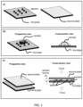
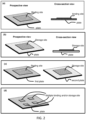
- the assays can be done by simply dropping a droplet of a sample (e.g., blood) of an unknown volume, spreading out the sample across the plates by pressing the plates together, incubating the sample for a period of time and taking a reading from multiple sites in the device.
- a sample e.g., blood
- the assay is extremely rapid for the reasons set out above. Further, because the plates do not need to be made with "walls" the manufacture of the device is straightforward.
- ports in any of the plates i.e., ports that could potentially be used for adding or removing sample or a reagent while the device is in closed position.
- the spacers are fixed to the one or more the plates are not able to change position or be swept away if the plate is immersed in an aqueous environment.
- the spacers are not spherical and they are not affixed to the surface of a plate via a weak force, such as an electrostatic force, gravity or the like.
- a plate having spacers may be a monolithic.
- the spacers are not pre-made and then affixed onto a plate (e.g., glued on or the like). Rather, the spacers may be grown and/or etched on a plate using an embossing and/ or microfabrication (e.g., a photolithography) process.
- the parameters of the spacers can be optimized so that, in the closed position, the top plate (which may be flexible) does not significantly deform over the part of the sample that is being analyzed (the "relevant volume" of the sample).
- the parameters of the spacers may be adjusted depending on the flexibility of the top plate. For example, if the top plate is more flexible, then the spacers may be closer together. Likewise, if the top plate is less flexible, then the spacers may be further apart.
- analytes do not migrate directionally through the device after the device is closed.
- the closed configuration there may be no sorting or fractionating of the analytes, no directional, forced, flow of the analytes through the device, (e.g., by gravity or electrophoresis), as described in Austin ( US 6,632,652 ).
- the device In many cases there is no need for the device to be coupled to a power supply to generate an electromotive force.
- the function of the coverplate is to seal the device to prevent liquid leaking out and, as such, the cover-plate is placed on top of the substrate plate at a time at which there is no sample on either of the plates. Such devices do not push liquid onto an open plate surface to produce a thin layer of sample that can be analyzed.
- the key function of the pillars is to "filter” or sort nanoparticles (e.g., cells or alike).
- the inter-pillar distance is determined by the nanoparticles being sorted, not for the goal of making the spacing between the cover plate and the substrate plate uniform.
- the accuracy of sorting is primarily controlled by the inter-pillar distances not the spacing between the plates, and controlling of the spacing between the plates is not regarded as significant.
- such disclosures would not lead one to modify plating spacing uniformity by changing pillar size, shape, inter-pillar spacing, etc.
- the present device is believed to provide an easy to use, inexpensive, easy to manufacture, and extremely rapid way to determine the absolute concentration of an analyte (or analytes, if the device is implemented in a multiplex way) in a liquid sample.
- the claimed device uses a pair of special plates that are movable to each other to manipulate a small volume sample or one or a plurality of reagents or both for a simpler, faster, and/or better assaying.
- the manipulation includes, but limited to, reshaping a sample, forcing a sample flow, making a contact between the sample and reagent, measuring sample volume, reducing diffusion distance, increasing collision frequency, etc. - all of them have benefit effects to certain assays.
- the special features and properties on the plates provide advantages in assaying.
- the claimed device can make at least a portion of a small droplet of a liquid sample deposited on a plate to become a thin film with a thickness that is controlled, predetermined, and uniform over large area.
- the uniform thickness can be as thin as less than 1 um.
- the invention allows the same uniform thickness be maintained for a long time period without suffering evaporation to environment.
- the predetermined uniform thin sample thickness formed by the invention can be utilized to determine the volume of a portion or entire of the sample without using any pipette or alike.
- the spacers (for controlling the spacing between two plates) have a pillar shape with a flat top and nearly uniform lateral cross-section. Such spacers offers many advantages in controlling a sample thickness over the spacers of ball (beads) shape.
- the claimed devices can make certain chemical reactions (or mixing) occur predominately only in a small portion of the sample, not in the other part of the sample, without using fluidic isolation between the two portion of the sample.
- Reading an assay can be performed by a mobile phone.
- polypeptide refers to polymers of amino acids of any length.
- the polymer may be linear or branched, it may comprise modified amino acids, and it may be interrupted by non-amino acids.
- the terms also encompass an amino acid polymer that has been modified; for example, disulfide bond formation, glycosylation, lipidation, acetylation, phosphorylation, or any other manipulation, such as conjugation with a labeling component.
- amino acid refers to either natural and/or unnatural or synthetic amino acids, including glycine and both the D or L optical isomers, and amino acid analogs and peptidomimetics.
- polynucleotide refers to a polymeric form of nucleotides of any length, either deoxyribonucleotides (DNA) or ribonucleotides (RNA), or analogs thereof.
- Polynucleotides may have any three-dimensional structure, and may perform any function, known or unknown.
- polynucleotides coding or non-coding regions of a gene or gene fragment, loci (locus) defined from linkage analysis, exons, introns, messenger RNA (mRNA), transfer RNA (tRNA), ribosomal RNA, ribozymes, small interfering RNA, (siRNA), microRNA (miRNA), small nuclear RNA (snRNA), cDNA, recombinant polynucleotides, branched polynucleotides, plasmids, vectors, isolated DNA (A, B and Z structures) of any sequence, PNA, locked nucleic acid (LNA), TNA (treose nucleic acid), isolated RNA of any sequence, nucleic acid probes, and primers.
- loci defined from linkage analysis, exons, introns, messenger RNA (mRNA), transfer RNA (tRNA), ribosomal RNA, ribozymes, small interfering RNA, (siRNA), microRNA (mi
- LNA often referred to as inaccessible RNA
- LNA nucleotide is a modified RNA nucleotide.
- the ribose moiety of an LNA nucleotide is modified with an extra bridge connecting the 2' and 4' carbons. The bridge "locks" the ribose in the 3'-endo structural conformation, which is often found in the A-form of DNA or RNA, which can significantly improve thermal stability.
- capture agent refers to a binding member, e.g. nucleic acid molecule, polypeptide molecule, or any other molecule or compound, that can specifically bind to its binding partner, e.g., a second nucleic acid molecule containing nucleotide sequences complementary to a first nucleic acid molecule, an antibody that specifically recognizes an antigen, an antigen specifically recognized by an antibody, a nucleic acid aptamer that can specifically bind to a target molecule, etc.
- a capture agent may concentrate the target molecule from a heterogeneous mixture of different molecules by specifically binding to the target molecule. Binding may be non-covalent or covalent.
- the affinity between a binding member and its binding partner to which it specifically binds when they are specifically bound to each other in a binding complex is characterized by a K D (dissociation constant) of 10 -5 M or less, 10 -6 M or less, such as 10 -7 M or less, including 10 -8 M or less, e.g., 10 -9 M or less, 10 -10 M or less, 10 -11 M or less, 10 -12 M or less, 10 -13 M or less, 10 -14 M or less, 10 -15 M or less, including 10 -16 M or less.
- K D dissociation constant
- a secondary capture agent which can also be referred to as a “detection agent” refers a group of biomolecules or chemical compounds that have highly specific affinity to the antigen.
- the secondary capture agent can be strongly linked to an optical detectable label, e.g., enzyme, fluorescence label, or can itself be detected by another detection agent that is linked to an optical detectable label through bioconjugation ( Hermanson, "Bioconjugate Techniques” Academic Press, 2nd Ed., 2008 ).
- capture agent-reactive group refers to a moiety of chemical function in a molecule that is reactive with capture agents, i.e., can react with a moiety (e.g., a hydroxyl, sulfhydryl, carboxyl or amine group) in a capture agent to produce a stable strong, e.g., covalent bond.
- a moiety e.g., a hydroxyl, sulfhydryl, carboxyl or amine group
- specific binding and “selective binding” refer to the ability of a capture agent to preferentially bind to a particular target analyte that is present in a heterogeneous mixture of different target analytes.
- a specific or selective binding interaction will discriminate between desirable (e.g., active) and undesirable (e.g., inactive) target analytes in a sample, typically more than about 10 to 100-fold or more (e.g., more than about 1000- or 10,000-fold).
- antibody is meant a protein consisting of one or more polypeptides substantially encoded by all or part of the recognized immunoglobulin genes.
- the recognized immunoglobulin genes include the kappa ( ⁇ ), lambda ( ⁇ ), and heavy chain genetic loci, which together comprise the myriad variable region genes, and the constant region genes mu ( ⁇ ), delta ( ⁇ ), gamma ( ⁇ ), sigma ( ⁇ ), and alpha ( ⁇ ) which encode the IgM, IgD, IgG, IgE, and IgA antibody "isotypes" or "classes” respectively.
- Antibody herein is meant to include full length antibodies and antibody fragments, and may refer to a natural antibody from any organism, an engineered antibody, or an antibody generated recombinantly for experimental, therapeutic, or other purposes.
- the term "antibody” includes full length antibodies, and antibody fragments, as are known in the art, such as Fab, Fab', F(ab')2, Fv, scFv, or other antigen-binding subsequences of antibodies, either produced by the modification of whole antibodies or those synthesized de novo using recombinant DNA technologies.
- antibody epitope can include proteins, carbohydrates, nucleic acids, hormones, receptors, tumor markers, and the like, and mixtures thereof.
- An antibody epitope can also be a group of antibody epitopes, such as a particular fraction of proteins eluted from a size exclusion chromatography column.
- an antibody epitope can also be identified as a designated clone from an expression library or a random epitope library.
- an “allergen,” as used herein is a substance that elicits an allergic, inflammatory reaction in an individual when the individual is exposed to the substance, e.g., by skin contact, ingestion, inhalation, eye contact, etc.
- An allergen may include a group of substances that together elicit the allergic reaction.
- nucleotide sequence When a nucleotide sequence is not fully complementary (100% complementary) to a non-target sequence but still may base pair to the non-target sequence due to complementarity of certain stretches of nucleotide sequence to the non-target sequence, percent complementarily may be calculated to assess the possibility of a non-specific (off-target) binding. In general, a complementary of 50% or less does not lead to non-specific binding. In addition, a complementary of 70% or less may not lead to non-specific binding under stringent hybridization conditions.
- binding conditions and “conditions suitable for binding,” as used herein with respect to binding of a capture agent to an analyte, e.g., a biomarker, a biomolecule, a synthetic organic compound, an inorganic compound, etc., refers to conditions that produce nucleic acid duplexes or, protein/protein (e.g., antibody/antigen) complexes, protein/compound complexes, aptamer/target complexes that contain pairs of molecules that specifically bind to one another, while, at the same time, disfavor to the formation of complexes between molecules that do not specifically bind to one another.
- protein/protein e.g., antibody/antigen
- a "diagnostic sample” refers to any biological sample that is a bodily byproduct, such as bodily fluids, that has been derived from a subject.
- the diagnostic sample may be obtained directly from the subject in the form of liquid, or may be derived from the subject by first placing the bodily byproduct in a solution, such as a buffer.
- exemplary diagnostic samples include, but are not limited to, saliva, serum, blood, sputum, urine, sweat, lacrima, semen, feces, breath, biopsies, mucus, etc.
- biotin moiety refers to an affinity agent that includes biotin or a biotin analogue such as desthiobiotin, oxybiotin, 2'-iminobiotin, diaminobiotin, biotin sulfoxide, biocytin, etc. Biotin moieties bind to streptavidin with an affinity of at least 10-8M.
- a biotin affinity agent may also include a linker, e.g., -LC-biotin, -LC-LC-Biotin, -SLC-Biotin or -PEGn-Biotin where n is 3-12.
- streptavidin refers to both streptavidin and avidin, as well as any variants thereof that bind to biotin with high affinity.
- marker refers to an analyte whose presence or abundance in a biological sample is correlated with a disease or condition.
- bond includes covalent and non-covalent bonds, including hydrogen bonds, ionic bonds and bonds produced by van der Waal forces.
- amplify refers to an increase in the magnitude of a signal, e.g., at least a 10-fold increase, at least a 100-fold increase at least a 1,000-fold increase, at least a 10,000-fold increase, or at least a 100,000-fold increase in a signal.
- entity refers to, but not limited to proteins, peptides, DNA, RNA, nucleic acid, molecules (small or large), cells, tissues, viruses, nanoparticles with different shapes, that would bind to a "binding site”.
- entity includes the capture agent, detection agent, and blocking agent.
- entity includes the “analyte”, and the two terms are used interchangeably.
- binding site refers to a location on a solid surface that can immobilize "entity” in a sample.
- entity partners refers to, but not limited to proteins, peptides, DNA, RNA, nucleic acid, molecules (small or large), cells, tissues, viruses, nanoparticles with different shapes, that are on a "binding site” and would bind to the entity.
- entity include, but not limited to, capture agents, detection agents, secondary detection agents, or "capture agent/analyte complex”.
- target analytes or “target entity” refers to a particular analyte that will be specifically analyzed (i.e. detected), or a particular entity that will be specifically bound to the binding site.
- smart phone or “mobile phone”, which are used interchangeably, refers to the type of phones that has a camera and communication hardware and software that can take an image using the camera, manipulate the image taken by the camera, and communicate data to a remote place.
- the Smart Phone can have a flash light.
- light refers to, unless specifically specified, an electromagnetic radiation with various wavelength.
- the term "average linear dimension" of an area is defined as a length that equals to the area times 4 then divided by the perimeter of the area.
- the area is a rectangle, that has width w, and length L, then the average of the linear dimension of the rectangle is 4*W*L/(2*(L+W)) (where "*" means multiply and "/" means divide).
- the average line dimension is, respectively, W for a square of a width W, and d for a circle with a diameter d.
- the area include, but not limited to, the area of a binding site or a storage site.
- periodic structure array refers to the distance from the center of a structure to the center of the nearest neighboring identical structure.
- the term "storage site” refers to a site of an area on a plate, wherein the site contains reagents to be added into a sample, and the reagents are capable of being dissolving into the sample that is in contract with the reagents and diffusing in the sample.
- relevant means that it is relevant to detection of analytes, quantification and/or control of analyte or entity in a sample or on a plate, or quantification or control of reagent to be added to a sample or a plate.
- hydrophilic means that the contact angle of a sample on the surface is less than 90 degree.
- hydrophobic means that the contact angle of a sample on the surface is equal to or larger than 90 degree.
- variable of a quantity refers to the difference between the actual value and the desired value or the average of the quantity.
- relative variation refers to the ratio of the variation to the desired value or the average of the quantity. For example, if the desired value of a quantity is Q and the actual value is (Q+ ⁇ ), then the ⁇ is the variation and the ⁇ /(Q+ ⁇ ) is the relative variation.
- relative sample thickness variation refers to the ratio of the sample thickness variation to the average sample thickness.
- optical transparent refers to a material that allows a transmission of an optical signal
- optical signal refers to, unless specified otherwise, the optical signal that is used to probe a property of the sample, the plate, the spacers, the scale-marks, any structures used, or any combinations of thereof.
- sample-volume refers to, at a closed configuration of a CROF process, the volume between the plates that is occupied not by the sample but by other objects that are not the sample.
- the objects include, but not limited to, spacers, air bubbles, dusts, or any combinations of thereof. Often none-sample-volume(s) is mixed inside the sample.
- saturation incubation time refers to the time needed for the binding between two types of molecules (e.g. capture agents and analytes) to reach an equilibrium.
- the “saturation incubation time” refers the time needed for the binding between the target analyte (entity) in the sample and the binding site on plate surface reaches an equilibrium, namely, the time after which the average number of the target molecules (the entity) captured and immobilized by the binding site is statistically nearly constant.
- the term "deviation of the final sample thickness" in a CROF means the difference between the predetermined spacer height (determined from fabrication of the spacer) and the average of the final sample thickness, wherein the average final sample thickness is averaged over a given area (e.g. an average of 25 different points (4mm apart) over 1.6 cm by 1.6 cm area).
- spacer height is the dimension of the spacer in the direction normal to a surface of the plate, and the spacer height and the spacer thickness means the same thing.
- lateral or “laterally” in a CROF process refers to, unless specifically stated, the direction that is parallel to a surface of the plate.
- width of a spacer in a CROF process refers to, unless specifically stated, a lateral dimension of the spacer.
- a spacer inside a sample means that the spacer is surrounded by the sample (e.g. a pillar spacer inside a sample).
- critical bending span of a plate in a CROF process refers the span (i.e. distance) of the plate between two supports, at which the bending of the plate, for a given flexible plate, sample, and compression force, is equal to an allowed bending. For example, if an allowed bending is 50 nm and the critical bending span is 40 um for a given flexible plate, sample, and compression force, the bending of the plate between two neighboring spacers 40um apart will be 50 nm, and the bending will be less than 50 nm if the two neighboring spacers is less than 40 um.
- a sample under a CROF process does not need to be flowable to benefit from the process, as long as the sample thickness can be reduced under a CROF process.
- a CROF process can reduce the tissue thickness and hence speed up the saturation incubation time for staining by the dye.
- reagents additions are needed are (a) blood cell counting where anticoagulant and/or staining reagent(s) may be added into a blood sample, and (b) immunoassays where detection agents are added to bind a target analyte in solution.
- an unclaimed method for reducing the time for mixing a reagent stored on a plate surface into a sample includes the following steps:
- the method of paragraph X5 can further include a step of incubation while the plates are in the closed configuration, wherein the incubation time is selected in such that results in a significant number of the reagents dissolved in the sample are contained in the relevant volume of the sample, wherein the relevant volume is the volume of the sample that sits on the storage site and the incubation is a process to allow the reagent to dissolve and diffuse in the sample.
- the relevant volume of the sample may be the volume of the sample that sits on (i.e. on top of) the binding site or the storage site.
- the ratio of the lateral dimension of the binding site or the storage site to the sample thickness at the closed configuration may be 1.5 3 or larger, 3 or larger, 5 or larger, 10 or larger, 20 or larger, 30 or larger, 50 or larger, 100 or larger, 200 or larger, 1000 or larger, 10,000 or larger, or a range between any two of the values.
- the ratio of the lateral dimension of the binding site or the storage site to the sample thickness at the closed configuration may be between 3 and 20 , 20 and 100 , and 100 and 1000 , and 1000 and 10,000 .
- the final reduced sample thickness may be significantly smaller than that of the area of the binding site, so that the entity in the sample area that is outside of the binding site will take longer time to bind to the binding site.
- the entity that bind to the binding sites will be primarily the entity in the sample volume that sites on the binding site (i.e. the sample volume that is just above the binding area). Then the calculation of the concentration of the entity in the sample would be based on the sample thickness and the binding site area.
- the final reduced sample thickness may be significantly smaller than that of the area of the storage site, so that the entity
- the entity that bind to the binding sites will be primarily the entity in the sample volume that sites on the binding site (i.e. the sample volume that is just above the binding area). Then the calculation of the concentration of the entity in the sample would be based on the sample thickness and the binding site area.
- the final sample thickness at the closed configuration of the plates may be a significant factor in reducing the saturation incubation time.
- the final sample thickness may be less than about 0.5 um (micrometer), less than about 1 um, less than about 1.5 um, less than about 2 um, less than about 4 um, less than about 6 um, less than about 8 um, less than about 10 um, less than about 12 um, less than about 14 um, less than about 16 um, less than about 18 um, less than about 20 um, less than about 25 um, less than about 30 um, less than about 35 um, less than about 40 um, less than about 45 um, less than about 50 um, less than about 55 um, less than about 60 um, less than about 70 um, less than about 80 um, less than about 90 um, less than about 100 um, less than about 110 um, less than about 120 um, less than about 140 um, less than about 160 um, less than about 180 um, less than about 200 um, or less than about 250 um.
- the final sample thickness may be less than about 300 um, less than about 350 um, less than about 400 um, less than about 450 um, less than about 500 um, less than about 550 um, less than about 600 um, less than about 650 um, less than about 700 um, less than about 800 um, less than about 900 um, less than about 1000 um (1 mm), less than about 1.5 mm, less than about 2 mm, less than about 2.5 mm, less than about 3 mm, less than about 3.5 mm, less than about 4 mm, less than about 5 mm, less than about 6 mm, less than about 7 mm, less than about 8 mm, less than about 9 mm, less than about 10 mm, or a range between any two of the values.
- the final sample thickness at the closed configuration may be less than 0.5 um (micron), less than 1 um, less than 5 um, less than 10 um, less than 20 um, less than 30 um, less than 50 um, less than 100 um, or less than 200 um. In other examples not forming part of the claimed invention, the final sample thickness at the closed configuration may be less than 300 um, less than 500 um, less than 800 um, less than 200 um, less than 1 mm (millimeter), less than 2 mm (millimeter), less than 4 mm (millimeter), less than 8 mm (millimeter), or a range between any two of the values.
- the Q-methods may make the final sample thickness uniform and flat surfaces of the first plate and the second plate are used.
- the sample incubation can be done in various temperatures, humidity, gas environment, and different time durations, with or without shaking.
- incubation Time After (d) and while the plates are in the closed configuration, incubating can be done for a time equal or less than a factor times the diffusion time of the entity in the sample diffusing across the sample thickness regulated by the plates at the closed configuration, and then stopping the incubation; wherein the incubation allows binding of the entity to the binding site; and wherein the factor is 0.0001, 0.001, 0.01, 0.1, 1, 1.1, 1.2, 1.3, 1.5, 2, 3, 4, 5, 10, 100, 1000, 10,000, or a range between any to the values. For example, if the factor is 1.1 and the diffusion time is 20 seconds, then the incubation time is equal to or less than 22 second. In one preferred embodiment, the factor is 0.1, 1, 1.5 or a range between any to the values.
- Incubation while the plates are in the closed configuration may involve a saturation incubation time of 0.001 sec or less, 0.01 sec or less, 0.1 sec or less, 1 sec or less, 5 sec or less, 10 sec or less, 20 sec or less, 30 sec or less, 40 sec or less, 1 min or less, 2 min or less, 3 min or less, 5 min or less, 10 min or less, 20 min or less, 30 min or less, 60 min or less, 90 min or less, 120 min or less, 180 min or less, 250 min or less, or a range between any two of these values.
- the saturation incubation time at the reduced sample thickness at the closed configuration may be 0.001 sec or less, 0.01 sec or less, 0.1 sec or less, 1 sec or less, 5 sec or less, 10 sec or less, 20 sec or less, 30 sec or less, 40 sec or less, 1 min or less, 2 min or less, 3 min or less, 5 min or less, 10 min or less, 20 min or less, 30 min or less, 60 min or less, 90 min or less, 120 min or less, 180 min or less, 250 min or less, or a range between any two of these values.
- Capture agents may be first immobilized at the binding site, so that the sample in contact with the binding site and the entity in the sample are captured by the capture agents, and finally detection agents may be added to be bound with the captured entity and the a signal from the detection agents will be read (e.g. by optical methods or electrical methods or a combination).
- Other reagents besides of capture agents and detection agents may be added (e.g. blocking agent).
- the added additional reagents can include detection agents, blocking agents, light signal enhancers, light signal quenchers, or others.
- the assay processes can be controlled by using different release time of the reagents stored on the same location. The different release time can be attached by adding other materials that have different dissolve rate.
- the reagent concentration mixed in the sample can be controlled by controlling the sample thickness (e.g. control the ratio of the sample thickness to the storage site area and/or the mixing time).
- the two plates i.e. the first plate and the second plate
- the two plates can have one side connected together during all operations of the plates (including the open and closed configuration), in which case the two plates open and close similar to a book.
- the two plates have rectangle (or square) shape and have two sides of the rectangle connected together during all operations of the plates.
- the pair of the plates can be spaced apart by a distance at least 10 nm, at least 100 nm, at least 1000 nm, at least 0.01cm, at least 0.1 cm, at least 0.5 cm, at least 1 cm, at least 2 cm, or at least 5 cm, or a range of any two of the values.
- Each plate has a sample contact surface and at least one of the contact surfaces of the plates is exposed when the plates are in the open configuration.
- the plates are facing each other (at least a part of the plates are facing each other) and a force is used to bring the two plates together.
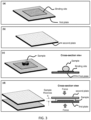
- the inner surfaces of the two plate compress the sample deposited on the plate(s) to reduce the sample thickness (while the sample has an open flow laterally between the plates), and the thickness of a relevant volume of the sample is determined by the spacers, the plates, and the method being used and by the sample mechanical/fluidic property.
- the thickness at a closed configuration can be predetermined for a given sample and given spacers, plates and plate pressing method.
- the term "regulation of the spacing between the inner surfaces of the plates by the spacers” or “the regulation of the sample thickness by the plates and the spacer”, or a thickness of the sample is regulated by the spacers and the plates” means that the thickness of the sample in a CROF process is determined by a given plates, spacers, sample, and pressing method.
- the regulated sample thickness at the closed configuration can be the same as the height of a spacer; in this case, at the closed configuration, the spacers directly contact both plates (wherein one plate is the one that the spacer is fixed on, and the other plate is the plate that is brought to contact with the spacer).
- the regulated sample thickness at the closed configuration can be larger than the height of a spacer; in this case, at the closed configuration, the spacers directly contacts only the plate that has the spacers fixed or attached on its surface, and indirectly contact the other plate (i.e. indirect contact).
- the term "indirect contact” with a plate means that the spacer and the plate is separated by a thin sample layer, which is termed “residual sample layer” and its thickness is termed "the residue thickness”.
- residual thickness can be predetermined (predetermined means prior to reach the closed configuration), leading to a predetermination of the sample thickness at the closed configuration. This is because the residue layer thickness is the same for the given conditions (the sample, spacers, plates, and pressing force) and can be pre-calibrated and/or calculated.
- the regulated sample thickness is approximately equal to the spacer height plus the sample residue thickness.
- the size and shape of the pillars are pre-characterized (i.e. pre-determined) before their use. And the pre-determined information are used to for later assaying, such as determination of the sample volume (or relevant volume) and others.
- Regulating of the sample thickness can include establishing the spacing between the plates with the spacers, a closing force applied to the plates, and physical properties of the sample optionally including at least one of viscosity and compressibility.
- the spacers are fixed on one or both of the plates before bringing the plates to the closed configuration.
- the term "a spacer is fixed with its respective plate” means that the spacer is attached to a plate and the attachment is maintained during a use of the plate.
- An example of "a spacer is fixed with its respective plate” is that a spacer is monolithically made of one piece of material of the plate, and the position of the spacer relative to the plate surface does not change.
- An example of "a spacer is not fixed with its respective plate” is that a spacer is glued to a plate by an adhesive, but during a use of the plate, the adhesive cannot hold the spacer at its original location on the plate surface (i.e. the spacer moves away from its original position on the plate surface).
- all of the spacers are fixed with their respective plates.
- a spacer can be fixed to a plate monolithically.
- the spacers can be fixed to its respective plate by one or any combination of the following methods and/or configurations: attached to, bonded to, fused to, imprinted, and etched.
- imprinted means that a spacer and a plate are fixed monolithically by imprinting (i.e. embossing) a piece of a material to form the spacer on the plate surface.
- the material can be single layer of a material or multiple layers of the material.
- etched means that a spacer and a plate are fixed monolithically by etching a piece of a material to form the spacer on the plate surface.
- the material can be single layer of a material or multiple layers of the material.
- fused to means that a spacer and a plate are fixed monolithically by attaching a spacer and a plate together, the original materials for the spacer and the plate fused into each other, and there is clear material boundary between the two materials after the fusion.
- bonded to means that a spacer and a plate are fixed monolithically by binding a spacer and a plate by adhesion.
- attached to means that a spacer and a plate are connected together.
- the spacers and the plate are made in the same materials. In other embodiment, the spacers and the plate are made from different materials. In other embodiment, the spacer and the plate are formed in one piece. In other embodiment, the spacer has one end fixed to its respective plate, while the end is open for accommodating different configurations of the two plates.
- each of the spacers independently is at least one of attached to, bonded to, fused to, imprinted in, and etched in the respective plate.
- independently means that one spacer is fixed with its respective plate by a same or a different method that is selected from the methods of attached to, bonded to, fused to, imprinted in, and etched in the respective plate.
- An inter-spacer distance is predetermined ("predetermined inter-spacer distance" means that the distance is known when a user uses the plates.).
- a larger plate holding force i.e. the force that holds the two plates together
- a smaller plate spacing for a given sample area
- a larger sample area for a given plate-spacing
- At least one of the plates is transparent in a region encompassing the relevant area, each plate has an inner surface configured to contact the sample in the closed configuration; the inner surfaces of the plates are substantially parallel with each other, in the closed configuration; the inner surfaces of the plates are substantially planar, except the locations that have the spacers; or any combination of thereof.
- Significantly flat is determined relative to the final sample thickness, and may have, depending upon on embodiments and applications, a ratio of to the sample thickness of less than 0.1%, less than 0.5%, less than 1%, less than 2%, less than 5%, or less than 10%, or a range between any two of these values.
- Flatness relative to the sample thickness may be less than 0.1%, less than 0.5%, less than 1%, less than 2%, less than 5%, less than 10%, less than 20%, less than 50%, or less than 100%, or a range between any two of these values.
- Significantly flat may mean that the surface flatness variation itself (measured from an average thickness) is less than 0.1%, less than 0.5%, less than 1%, less than 2%, less than 5%, or less than 10%, or a range between any two of these values.
- flatness relative to the plate thickness may be less than 0.1%, less than 0.5%, less than 1%, less than 2%, less than 5%, less than 10%, less than 20%, less than 50%, or less than 100%, or a range between any two of these values.
- the spacers can be fabricated on a plate in a variety of ways, using lithography, etching, embossing (nanoimprint), depositions, lift-off, fusing, or a combination of thereof.
- the spacers are directly embossed or imprinted on the plates.
- the spacers are made by directly embossing a surface of a CROF plate.
- the nanoimprinting may be done by roll to roll technology using a roller imprinter, or roll to a planar nanoimprint. Such process has a great economic advantage and hence lowering the cost.
- the spacers are deposited on the plates.
- the deposition can be evaporation, pasting, or a lift-off.
- the spacer is fabricated first on a carrier, then the spacer is transferred from the carrier to the plate.
- the lift-off a removable material is first deposited on the plate and holes are created in the material; the hole bottom expose the plate surface and then a spacer material is deposited into the hole and afterwards the removable material is removed, leaving only the spacers on the plate surface.
- the spacers deposited on the plate are fused with the plate.
- the spacer and the plates are fabricated in a single process. The single process includes imprinting (i.e. embossing, molding) or synthesis.
- At least two of the spacers are fixed to the respective plate by different fabrication methods, and optionally wherein the different fabrication methods include at least one of being deposition, bonded, fuse, imprinted, and etched.
- one or more of the spacers are fixed to the respective plate(s) is by a fabrication method of being bonded, being fused, being imprinted, or being etched, or any combination of thereof.
- the fabrication methods for forming such monolithic spacers on the plate include a method of being bonded, being fused, being imprinted, or being etched, or any combination of thereof.
- scale-marker(s) refers to the scale-marker(s) that able to assist a quantification (i.e. dimension measurement) or a control of the relevant area and/or the relative volume of a sample.
- the scale-markers are on the first plate or the second plate, on both on plates, on one surface of the plate, on both surfaces of the plate, between the plates, near the plates, or any combination of thereof.
- the scale-markers are fixed on the first plate or the second plate, on both on plates, on one surface of the plate, on both surfaces of the plate, between the plates, near the plates, or any combination of thereof.
- the scale-markers are deposited on the first plate or the second plate, on both on plates, on one surface of the plate, on both surfaces of the plate, between the plates, near the plates, or any combination of thereof.
- the scale-markers are a or a plurality of object(s) with known dimensions and/or known separation distances.
- objects include, not limited to, rectangles, cylinders, or circles.
- the scale-markers are a ruler, which has scale scale-marks that are configured to measure a dimension of an object.
- the scale-marks are in the scale of nanometer (nm), microns (um) or millimeter (mm) or other sizes.
- the scale marks are etched scale-marks, deposited materials, or printed materials.
- the materials for the scale-markers are the materials that absorbing the light, reflecting light, scattering light, interfering light, diffracting light, emitting light, or any combination of thereof.
- the makers are the spacers, which server dual functions of "regulating sample thickness” and “providing scale-marking and/or dimension scaling".
- a rectangle spacer with a known dimension or two spacers with a known separation distance can be used to measure a dimension related to the sample round the spacer(s). From the measured sample dimension, one can calculate the volume of the relevant volume of the sample.
- the scale-markers is configured to at least partially define a boundary of the relevant volume of the sample.
- At least one of the scale-markers is configured to have a known dimension that is parallel to a plane of the lateral area of the relevant volume of the sample.
- At least a pair of the scale-markers are separated by a known distance that is parallel to a plane of the lateral area.
- the scale-markers are configured for optical detection.
- the scale-markers are arranged in a regular array with a known lateral spacing.
- each scale-marker independently has a lateral profile that is at least one of square, rectangular, polygonal, and circular.
- some spacers also play a role of scale-marker to quantification of a relevant volume of the sample.
- a binding site(s) (that immobilizes the analytes), storage sites, or alike, serves as a scale-marker(s).
- the site with a known lateral dimension interacts with light generating a detectable signal, that reals the known lateral dimension of the site, hence serving a scale-marker(s).
- an assay has a binding site (i.e. the area with capture agents) of 1,000 um by 1000 um on a first plate of a CROF process (which has a surface large than the binding site); at the closed configuration of the plates, a sample with analytes is over the binding site, has a thickness of about 20 um (in the bind site area) and an area larger than the binding site and is incubated for a time equal to the target analyte/entity diffusion time across the sample thickness.
- a binding site i.e. the area with capture agents
- a first plate of a CROF process which has a surface large than the binding site
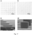
- the spacers are monolithically made on the X-Plate by embossing (e.g. nanoimprinting) a thin plastic film using a mold, and are made of the same materials.
- the spacers are monolithically made on the X-Plate by embossing (e.g. nanoimprinting) a thin plastic film using a mold, and are made of the same materials, and the thickness of the X-Plate is from 50um to 250um.
- the spacers are monolithically made on the X-Plate and are made of the same materials, and the thickness of the X-Plate is from 50um to 500um.
- the spacers are monolithically made on the X-Plate a thin plastic film using a mold, and are made of the same materials, and the thickness of the X-Plate is from 50um to 250um.
- the spacers are monolithically made on the X-Plate by embossing (e.g. nanoimprinting) a thin plastic film using a mold, and are made of the same materials, where the plastic film are either PMMA (polymethyl methacrylate) of PS (polystyrene).
- the spacers are monolithically made on the X-Plate by embossing (e.g. nanoimprinting) a thin plastic film using a mold, and are made of the same materials, where the plastic film are either PMMA (polymethyl methacrylate) of PS (polystyrene) and the thickness of the X-Plate is from 50um to 500um.
- embossing e.g. nanoimprinting
- the spacers are monolithically made on the X-Plate by embossing (e.g. nanoimprinting) a thin plastic film using a mold, and are made of the same materials, where the plastic film are either PMMA (polymethyl methacrylate) of PS (polystyrene) and the thickness of the X-Plate is from 50um to 250um.
- embossing e.g. nanoimprinting
- the spacers are monolithically made on the X-Plate by embossing (e.g. nanoimprinting) a thin plastic film using a mold, and are made of the same materials, where the plastic film are either PMMA (polymethyl methacrylate) of PS (polystyrene), and the spacers have either a square or rectangle shape, and have the same spacer height.
- embossing e.g. nanoimprinting
- the spacers have a square or rectangle shape (with or without round corners).
- the spacers have square or rectangle pillars with the pillar width (spacer width in each lateral direction) between 1um to 200um; pillar period (i.e. spacer period) from 2um - 2000um, and pillar height (i.e. spacer height) from 1um - 100um.
- the spacers made of PMMA or PS have square or rectangle pillars with the pillar width (spacer width in each lateral direction) between 1um to 200um; pillar period (i.e. spacer period) from 2um - 2000um, and pillar height (i.e. spacer height) from 1um - 100um.
- the spacers are monolithically made on the X-Plate and are made of the same materials, and the spacers have square or rectangle pillars with the pillar width (spacer width in each lateral direction) between 1um to 200um; pillar period (i.e. spacer period) from 2um - 2000um, and pillar height (i.e. spacer height) from 1um - 10um.
- the spacers are monolithically made on the X-Plate and are made of the same materials selected from PS or PMMA or other plastics, and the spacers have square or rectangle pillars with the pillar width (spacer width in each lateral direction) between 1um to 200um; pillar period (i.e. spacer period) from 2um - 2000um, and pillar height (i.e. spacer height) from 10 um - 50um.
- one plate is X-Plate and the other plate is a planar thin film, wherein the thickness of at least one of the plates is in a range of from 10 um to 250 um; wherein the spacers are fixed on the X-Plate, and wherein the plates and the spacers can have the same materials or different materials and are made of PMMA (polymethyl methacrylate), PS (polystyrene), or a material of similar mechanical properties as PMMA or PS.
- PMMA polymethyl methacrylate
- PS polystyrene
- one plate is X-Plate and the other plate is a planar thin film, wherein the thickness of at least one of the plates is in a range of from 250 um to 500 um; wherein the spacers are fixed on the X-Plate, and wherein the plates and the spacers can have the same materials or different materials and are made of PMMA (polymethyl methacrylate), PS (polystyrene), or a material of similar mechanical properties as PMMA or PS.
- PMMA polymethyl methacrylate
- PS polystyrene
- one plate is X-Plate and the other plate is a planar thin film, wherein the thickness of at least one of the plates is in a range of from 10 um to 250 um; wherein the spacers are fixed on the X-Plate, and are an array of square or rectangle pillars with the pillar width (spacer width in each lateral direction) between 1um to 200um; pillar period (i.e. spacer period) from 2um - 2000um, and pillar height (i.e.
- the plates and the spacers can have the same materials or different materials and are made of PMMA (polymethyl methacrylate), PS (polystyrene), or a material of similar mechanical properties as PMMA or PS.
- PMMA polymethyl methacrylate
- PS polystyrene
- Guard Ring Some embodiments have a guard ring to prevent sample flow out of the plate surface. Some embodiments of the guard ring is an enclosed wall around the sample area. The wall has a height equal to the spacer height or different from the spacer height. The wall ca be a significant distance away from the sample measurement area.
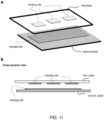
- the movable plates in a CROF process may include and/or may be coupled to a hinge, a stage, or some other positioning system that is configured to transition the plates between an open configuration and a closed configuration.
- Movable plates may be coupled together with one or more joints in a manner that leaves an opening to access the space between the plates (e.g., to insert and/or remove sample), provided that at least one of the joints and/or at least one of the plates is flexible enough to achieve the described open and closed configurations.
- a membrane pump is not considered to be a movable plate(s).
- the present invention provides the means to improve the uniformity.
- the factors that can degrade the uniformity of the plate spacing in CROF include (a) a local bending of a plate, (b) a non-flatness of the inner surface of a plate, and (c) dusts.
- Improving the spacing (hence sample thickness) uniformity can be done using certain design in the plates (mechanical strength, thickness, etc.), spacer size, number of spacers, layout of the spacers, inter spacer spacing, the precision of spacer height, among other things to overcome the factors that cause a non-uniformity.
- One or both of the CROF plates are flexible.
- a flexible plate e.g. a plastic thin film
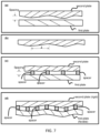
- the flexibility of the plate(s) can lead a local bending (e.g. sag, namely bending inward) of the plate at the locations that are between the two neighboring spacers, leading to a poor sample thickness uniformity.
- a poor sample thickness uniformity has many disadvantages, such as large errors in determining the sample volume and/or analytes concentration, variation of the incubation time, etc.
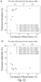
- a CROF device has one rigid plate with a flat sample surface and one flexible plate that has local bending between two neighboring spacers, if the inter spacer distance is too large ( Fig. 5a ).
- the inter spacer distance is set to be equal or smaller the critical bending span of the flexible plate ( Fig. 5b ).
- the inter spacer distance should less than the smallest of the critical bending span of the two plates.
- an unclaimed method for uniformly regulating a thickness of a relevant volume of a sample using two plates includes the following steps:
- the configuration of the spacers comprises selecting a proper inter spacer distance.
- the inter spacer distance can be selected, so that for an allowed sample thickness variation, given two plate, and a compression method, the bending of the two plates, under the compression method, is equal to or less than the allowed sample thickness variation.
- the regulated sample thickness at the closed configuration can be thinner than the maximum thickness of the sample when the plates are in the open configuration
- the configuration of the spacers and plates comprises selecting a proper inter spacer distance.
- the inter spacer distance can be selected so that for an allowed sample thickness variation, given two plate, and a compression method, the bending of the two plates, under the compression method, is equal to or less than the allowed sample thickness variation.
- the regulated sample thickness at the closed configuration can be thinner than the maximum thickness of the sample when the plates are in the open configuration
- Small interspace spacing can also allow the use of flexible thin films (e.g. Plastic file of 100um thick) by making the inter-spacer distance less than the bending f the plate between two spacers.
- flexible thin films e.g. Plastic file of 100um thick
- the ratio of inter spacer distance to the critical bending span of the plate may be at most 0.001 %, at most 0.001 %, at most 0.001 %, at most 0.01 %, at most 0.1 %, at most 1 %, at most 10 %, at most 20 %, at most 50 %, at most 70 %, at most 100 %, or a range between any two of the values.
- Certain embodiments of the present invention solve the problem by using a proper flexible plate(s) and inter spacer distance to limit the effect of the dust in a small area around the dust, while allowing the area outside the small area to have a final plate spacing and sample thickness set (regulated) by the spacers).
- Fig. 6b illustrates that, to overcome the effects of the dust, one flexible plate with a proper flexibility is used to limit the dust area, and it is used together with a rigid plate that has fixed spacers.
- Fig. 6c shows another solution for reducing the dust effect, where the spacers are fixed on the flexible plate.
- another solution is to make both plate flexible.
- the proper flexibility of the plates to minimize the effects of the dust in a CROF process can be selected from the thickness and the mechanical property of the plate.
- an unclaimed method for minimizing the effects of a dust on regulating a thickness of a relevant volume of a sample includes the steps of:
- the precision, uniformity, or easy-to-use of regulating a thickness of a relevant volume of a sample can be improved by compressing the sample with two plates.
- an unclaimed method for uniformly binding an entity in a sample into a binding site of a plate includes the following steps:
- an unclaimed method for regulating a thickness of a relevant volume of a sample includes the following steps:
- the uniformity of the thickness of the relevant volume of the sample is such that the sample thickness at the closed configuration has a relative variation of at most 0.001%, at most 0.01%, at most 0.05%, at most 0.1%, at most 0.5%, at most 1%, at most 2 %, at most 5 %, at mos10 %, at most 20%, at most 30%, at most 50%, at most 75%, at mos90%, less than 100%, or a range between any two of these values.
- the uniformity of the thickness of the relevant volume of the sample is preferably such that the sample thickness at the closed configuration has a relative variation of at most 0.1%, at most 0.5%, at most 1%, at most 2 %, at most 5 %, at mos10 %, at most 20%, at most 30%, at most 50%, or a range between any two of these values.
- the saturation incubation time can vary from location to location in the binding site, forcing a longer saturation incubation time to ensure all locations in the binding site having reached the saturation.
- the binding site can be put on a signal amplification surface (SAS) to amplify the signal for achieving higher sensitivity.
- SAS signal amplification surface
- Signal amplification surfaces may also be referred to as signal amplification layers (SAL).
- the general structures of SAL comprise nanoscale metal-dielectric/semiconductor-metal structures, which amplifies local surface electric field and gradient and light signals.
- the amplification are the high at the location where there are the sharp (i.e. large curvature) edges of a metal structure and the between a small gaps of the two metal structures.
- the highest enhancement regions are those having both the sharp edges and the small gaps.
- the dimensions for all metallic and non-metallic micro/nanostructures generally are less than the wavelength of the light the SAL amplifies (i.e., subwavelength).
- Quantification and/or control of a relevant volume of a sample is useful for quantification and/or control of the concentration of chemical compounds (including analytes, entity, reagents, etc.) in the sample.
- a sample volume quantification includes a use of a metered pipette (e.g., Eppendorf's "Research plus pipette, adjustable, 0.5-10 ⁇ L", SKU #3120000020), or a geometry.
- a metered pipette e.g., Eppendorf's "Research plus pipette, adjustable, 0.5-10 ⁇ L", SKU #3120000020
- metering devices are inconvenient to use and/or expensive.
- Quantification and/or control of a relevant volume of a sample deposited on a plate can be done without using a metered pipette and/or a fixed microfluidic channel.
- the relevant volume which can be a portion or the entire volume of the sample, is relevant to the quantification and/or control of the concentration of target analyte and/or entity in the sample.
- the method for quantifying a relevant volume in a sample may include:
- MS1. Quantifying of a relevant volume of the sample while the plates are at a closed configuration includes, but not limited to, each of the following five methods:
- the mechanical methods include, but not limited to, a use of the spacers (i.e. the mechanical device that regulate the spacing between the inner surfaces of the substrate and the cover-plate to a predetermined value), mechanical probe or rulers, sound waves (e.g. reflection and/or interference of ultrasound wave to measure the spacing), or any combination of thereof.
- the spacers i.e. the mechanical device that regulate the spacing between the inner surfaces of the substrate and the cover-plate to a predetermined value
- mechanical probe or rulers e.g. reflection and/or interference of ultrasound wave to measure the spacing
- the optical methods include, but not limited to, a use of light interference, or optical imaging (e.g. taking a 2D (two-dimensional)/3D (three-dimensional) image of the sample, optical imaging of multiple times (with different viewing angles, different wavelength, different phase, and/or different polarization), image processing, or any combination of thereof.
- a use of light interference or optical imaging (e.g. taking a 2D (two-dimensional)/3D (three-dimensional) image of the sample, optical imaging of multiple times (with different viewing angles, different wavelength, different phase, and/or different polarization), image processing, or any combination of thereof.
- the electrical methods include, but not limited to, capacitive, or resistive or impedance measurements, or any combination of thereof.
- predetermined one or several parameter(s) related to the relevant volume of the sample wherein the predetermined parameter is the predetermined the spacer height.
- the parameters related to the relevant volume of the sample can be the parameters at a closed configuration, that include, but not limited to, (i) the spacing between the inner surfaces of the first plate and the second plate (in CROF), (ii) the sample thickness, (iii) the entire or a relevant portion of the sample area, (iv) the entire or a relevant portion of the sample volume, or (v) any combination of thereof.
- the quantification of the sample volume or a relevant sample volume may comprise steps of (i) multiplying the sample thickness by the entire sample area to get the entire sample volume, (ii) multiplying the sample thickness by the relevant sample area to get the relevant sample volume, or (iii) multiplying the relevant sample thickness by the entire or relevant sample area to get the relevant sample volume.
- the quantification of the relevant volume of the sample may be by measuring the lateral area of the relevant volume of the sample, then using it with the thickness of the relevant volume to determine the volume of the relevant volume of the sample, wherein the thickness of the relevant volume is determined from the information of the spacer, and the information of the spacer include the spacer height;
- the quantification of the relevant volume of the sample may be by measuring the lateral area of the relevant volume of the sample and the spacer together, then using it with the thickness of the relevant volume and the volume of the spacers to determine the volume of the relevant volume of the sample, wherein the thickness of the relevant volume is determined from the inform of the spacer;
- the quantification of the relevant volume of the sample may be by measuring the lateral area and the thickness of the relevant volume of the sample;
- the quantification of the relevant volume of the sample may be by measuring the volume of the relevant volume of the sample optically.
- Scale marks may be used to assist the quantification of a relevant volume of the sample while the plates are at a closed configuration, wherein the scale markers, their use and measurements, etc. are described in Section 2.
- the quantification of the relevant volume of the sample may comprise a step of substracting the none-sample volume, wherein the none-sample volume is determined as described.
- an unclaimed method for quantifying analytes in a relevant volume of a sample includes the following steps:
- Either method may further comprise a step of calculating the analytes concentration by dividing the signal related to the analytes from the relevant volume of the sample by the volume of the relevant volume.
- One or both plates further comprise a binding site, a storage site, or both.
- the signal related to the analyte can be a signal directly from the analytes or a label attached to the analyte.
- the concentration of target analytes and/or entity in a sample can be quantified or controlled, if the number of target analytes and/or entity in the sample are quantified, as well as the relevant volume of the sample is quantified.
- the reading of a signal from a sample may use a scanning method, where a reader (e.g. photodetectors or camera) reads a portion of the sample (or plate) and then moves to another portion of the sample (or plate), and such process continues until certain pre-specified port of the sample (or plate) being read.
- the scan reading of a sample covers all part of the sample (or the plate) or a fraction of the sample (or the plate).
- the scan reading may be assisted by the location markers that indicate a location of the sample (or the plate).
- the location markers is the periodic spacers, which has a fixed period and location, or the markers for the relevant area which also has predetermined location and size for indicating a location of the sample or plate.
- An analyte can be detected and/or quantified (i.e. assayed) by measuring a signal related to the analyte, wherein the signal is an optical signal, electrical signal, mechanical signal, chemi-physical signal, or any combination of thereof.
- the analyte assaying can be performed when the two plates in a CROF device are close to each other.
- the analyte assaying may be performed when the two plates in a CROF device are separated from each other.
- the optical signal includes, but not limited to, light reflection, scattering, transmission, absorption, spectrum, color, emission, intensity, wavelength, location, polarization, luminescence, fluorescence, electroluminescence, chemoluminescence, eletrochemoluminescence, or any combination of thereof.
- the optical signal is in the form of optical image (i.e. light signal vs location of the sample or device) or a lump sum of all photons coming from a given area or volume.
- a preferred wavelength of the light is in a range of 400 nm to 1100 nm, a range of 50 nm to 400 nm, a range of 1 nm to 50 nm, or a range of 1100 to 30,000 nm. Another preferred wavelength is in terahertz.
- the electrical signal includes, but not limited to, charge, current, impedance, capacitance, resistance, or any combination of thereof.
- the mechanical signal includes, but not limited to, mechanical wave, sound wave, shock wave, or vibration.
- the chemi-physical signal includes, but not limited to, PH value, ions, heat, gas bubbles, color change, that are generated in an reaction.
- the label is a bead and the label is attached to the label through an analyte specific binding process (e.g. use detection agent to bind the bead to the analyte, use capture agent to capture the analyte with bead, use a capture agent to bind the analyte and then use detection agent to attach the bead, or other approaches.
- analyte specific binding process e.g. use detection agent to bind the bead to the analyte, use capture agent to capture the analyte with bead, use a capture agent to bind the analyte and then use detection agent to attach the bead, or other approaches.
- the capture and detection agents bind the analyte specifically), then a measurement is used to identify each of the beads that are attached to the analytes, and count them.
- Each of the analyte or the beads may be sensed and counted by optical means (such as (i) optical labels and reading of the labels, (ii) surface plasmon resonance, (iii) optical interferences, (iv) electrical methods (e.g. capacitance, resistance, impedance, etc.), or others.
- optical means such as (i) optical labels and reading of the labels, (ii) surface plasmon resonance, (iii) optical interferences, (iv) electrical methods (e.g. capacitance, resistance, impedance, etc.), or others.
- the sensors can be on the surface of the first plate and/or the second plate.
- Methods may include determining the analyte concentration in (a) surface immobilization assay, (b) bulk assay (e.g., blood cell counting), and (c) others.
- the measuring a signal may be to measure the number of the analytes in the sample, or measure the number of a label being attached to the analytes in the sample.
- the “measuring signal” may be to (a) identify each of the analyte or the label attached to each analyte, and (b) count their number.
- the analytes detection can be an electrical method when electrodes are put on one or both of the first and second plates (this applies to any of the methods and devices that uses CROF).
- the electrodes measure the charge, current, capacitance, impedance, or resistance of a sample, or any combination of thereof.
- the electrodes measure an electrolyte in a sample.
- the electrodes have a thickness equal or less than the thickness spacer. In some embodiments, the electrode serve as a part of the spacers.
- the electrodes are made of various conducting materials.
- a preferred electrode material is gold, silver, aluminum, copper, platinum, carbon nanotubes, or any combination of thereof.
- the measuring may use the devices that is a camera or photodetector plus an optional processor configured to make the measurement.
- the concentration determining devices may comprise a processor configured to determine the concentration from the measurements (volume, area, thickness, number of analytes, intensity)
- a further concentration determining device can be configured to determine the concentration of the target analytes in the relevant volume from the measured lateral area, the thickness, and the measured amount of the target molecules.
- the signals from the sample, analytes, and entity, binding sites, reagents, CROF plates, or any combinations of thereof detected and analytes may use pixelated reading and analysis described in the disclosure, while some other methods are described in Publication Number: WO2014144133 A and Application Number: PCT/US2014/028417 (Chou et al , "Analyte Detection Enhancement By Targeted Immobilization, Surface Amplification, And Pixelated Reading And Analysis").
- the signal may be electromagnetic signal, including electrical and optical signals with different frequencies, light intensity, fluorescence, chromaticity, luminescence (electrical and chemo-luminescence), Raman scattering, time resolved signal (including blinking).
- the signals also can be the forces due to local electrical, local mechanical, local biological, or local optical interaction between the plate and the reading device.
- the signal also includes the spatial (i.e. position), temporal and spectral distribution of the signal.
- the detection signal also can be absorption.
- the analyte include proteins, peptides, DNA, RNA, nucleic acid, small molecules, cells, nanoparticles with different shapes.
- the targeted analyte can be either in a solution or in air or gas phase.
- the sensing includes the detection of the existence, quantification of the concentration, and determination of the states of the targeted analyte.
- Electric field can be used to assist molecular selectivity, or bonding, and detection.
- the methods may include, but not limited to, far-field optical methods, near-field optical methods, epi-fluorescence spectroscopy, confocal microscopy, two-photon microscopy, and total internal reflection microscopy, where the target analytes are labelled with an electromagnetic radiation emitter, and the signal in these microscopies can be amplified by the amplification surface of a CROF plate.
- the signal may comprise the information of the position, local intensity, local spectrum, local polarization, local phase, local Raman signature of said signals, or any combination of thereof.
- the detection of a signal may be to measure a lump-sum signal from an area (i.e. the signal from the area, regardless which location in the area).
- the detection of signal may be to measure an signal image of an area (i.e. signal vs location); namely, the area is divided into pixels and the signal from each pixel of the area is individually measured, which is also termed "PIX" or "pixelated imaging detection".
- the individual measurement of each pixel can be in parallel or sequential or a mix.
- the reading may use appropriate detecting systems for the signal to be detected in sequence or in parallel or their combination.
- a sequential detection one or several pixels are detected a time, and scanner will be used to move the detection into other areas of the SAL.
- a parallel detection a multipixel detector array, such as imaging camera (e.g. CCD's), will be used to take detect the signals from different pixels at the same time.
- the scan can be single path or multi-path with a different pixel size for each path.
- Fig. 2C of PCT/US2014/028417 schematically illustrates pixelated reading on an x, y, z stage.
- the pixel size for the reading/detection will be adjusted to for the balance of optical resolution and total reading time.
- a smaller pixel size will take a longer time for reading/scanning the entire or fraction of the SAL.
- a typical pixel size is 1um to 10 um in size.
- the pixel has different shapes: round, square and rectangle.
- the lower limit of the pixel size is determined by the optical resolution of the microscope system, and the higher limit of the pixel size is determined in order to avoid reading error from the uneven optical response of the imager (optical aberration, illumination uniformity, etc.).
- a reading system comprises (a) a plate or plates used for CROF; (b) a reading device 205 for producing an image of signals emanating from a surface of said plate, wherein signals represent individual targeted analyte binding events; (c) a device assembly 300 that holds the plate and the imager; (d) an electronics and a data storage 301 for storing said image; and (e) a computer comprising programming for identifying and counting individual binding events in an area of the image.
- the device assembly 300 controls or changes the relative position between the plate and the reading device, in at least one of the three (x, y, z) orthogonal directions, for reading the signal.
- the device assembly optionally comprises a scanner 301.
- the scanner 301 scans in in at least one of the three (x, y, z) orthogonal directions.
- the reading device 302 can be a CCD camera.
- the reading device 302 can be a photodetector comprising one or more other optical devices that are selected from optical filters 303, spectrometer, lenses 304, apertures, beam splitter 305, mirrors 306, polarizers 307, waveplates, and shutters.
- he reading device 302 is a smartphone or mobile phone, which have the capability of local and remote communications.
- the reading device collects the position, local intensity, local spectrum, local Raman signature of said signals, or any combination of thereof.
- Optical filters 303, light beam splitters 305, optical fibers, a photodetector (e.g. pn junction, a diode, PMT (photomultiplier tube), or APD (Avalanch Photo Diode), imaging camera (e.g. CCD's, or cellphone camera) and spectrometer together with a scanner provided by the device assembly 301 can be coupled to a microscope system which uses a far-field confocal setting or a wide-field view setting.
- a photodetector e.g. pn junction, a diode, PMT (photomultiplier tube), or APD (Avalanch Photo Diode
- imaging camera e.g. CCD's, or cellphone camera
- spectrometer e.g. CCD's, or cellphone camera
- the reading can be performed by recording the brightness, temporal change and spectral change of one or a few pixels a time and raster scanning the entire interested area of the SAL.
- a camera can be used to record the brightness and temporal change of the entire or a fraction of SAL area a time.
- Proper optical filters and light beam manipulators polarizer, beam splitters, optical fibers, etc. are used to ensure only the desired signal is collected and detected.
- Fig. 9 of PCT/US2014/028417 schematically illustrates one arrangement of components for this system.
- PIX Pixelated Analysis
- signal detected in a pixelated manner refers to the method where the area that has signal(s) is divided into pixels and the signal from each pixel of the area is individually measured, which is also termed "PIX" or "pixelated imaging detection".
- PIX pixelated imaging detection
- the individual measurement of each pixel can be in parallel or sequential or a mix.
- the analysis may comprise to analyze the spatial, tempo, spectral information of the signal.
- the analysis may include, but not limited to, statistical analysis, comparison, integration, and others.
- Fig. 5 of PCT/US2014/028417 shows a flow chart for method.
- the analysis method -1 comprises (1) determine the local background signal intensity, (2) determine local signal intensity for one label, two labels, etc.; and (3) determine the total number of labels in the imaged area.
- the background signal means the signal that is generated under the exact conditions as other samples, except that the sample does not contain any targeted analytes.
- One method of Analysis-1 uses EM-CCD to record the spatial distribution bioassay signal intensity.
- a cellphone smart phone, mobile phone
- a cellphone is used for imaging of the signal.
- the analysis-2 method comprises (1) determine the local background signal spectrum, (2) determine local signal spectrum for one label, two labels, etc.; and (3) determine the total number of labels in the imaged area.
- Analysis-2 is based on using high-resolution spectrometer combined with a confocal microscope setup to record spatial distribution of bioassay signal spectra. Some details of Analysis-2 the analysis are:
- the analysis-3 (Sensing by Pixelated SERS signal).
- One method of signal analysis, Analysis-3 comprises (1) determine the local background signal of "surface enhanced Raman scattering" (SERS) signature, (2) determine local SERS signal for one label, two labels, etc.; and (3) determine the total number of labels in the imaged area.
- SERS surface enhanced Raman scattering
- Analysis-3 is based on using high-resolution spectrometer combined with a confocal microscope setup to record spatial distribution of bioassay signal SERS spectra.
- the analysis-4 method comprises (1) take an image (i.e. picture) by of the relevant area of the plate by a smartphone; (2) analysis the data locally (use the same smartphone to do analysis), remotely (transfer data to a remote site for analysis) or both; and (3) display the data on the smartphone with or without an expert advice on the meaning of the data.
- the analysis may comprise imaging processing methods, including, not limited to, the methods in Open-CV or Image-J.
- optical labels described in the entire disclosure can be used with the methods and devices described.
- a label(s) can be attached to a detection agent(s), an analyte(s) or an entity (ties).
- the label can be an optical label, an electric label, enzymes that can be used to generate an optical or electrical signal, or any combination of thereof.
- a detection agent(s), an analyte(s) or an entity (ties) may be attached a connection molecule (e.g. protein, nucleic acid, or other compounds) which later is attached to a label.
- An optical label is an object that can generate an optical signal, wherein the generation of the optical signal includes, but not limited to, light (i.e. photon's) reflection, scattering, transmission, absorption, spectrum, color, emission, intensity, wavelength, location, polarization, luminescence, fluorescence, electroluminescence, photoluminescence (fluorescence), chemoluminescence, electrochemiluminescence, or any combination of thereof.
- the optical signal can be in the form of optical image (i.e. light signal vs location of the sample or device) or a lump sum of all photons coming from a given area or volume.
- a preferred wavelength of the light is in a range of 400 nm to 1100 nm, a range of 50 nm to 400 nm, a range of 1 nm to 50 nm, or a range of 1100 to 30,000 nm.
- Another preferred wavelength is in terahertz.
- the optical label may be beads, nanoparticles, quantum dots, or any combination of thereof.
- the diameter of the bead, nanoparticles, or quantum dots may be 1 nm or less, 2 nm or less, 5 nm or less, 10 nm or less, 20 nm or less, 30 nm or less, 40 nm or less, 50 nm or less, 60 nm or less, 70 nm or less, 80 nm or less, 100 nm or less, 120 nm or less, 200 nm or less,300 nm or less, 500 nm or less, 800 nm or less, 1000 nm or less, 1500 nm or less, 2000 nm or less, 3000 nm or less, 5000 nm or less, or a range between any two of the values.
- the beads or quantum dots can be used as labels and precoated on the plates of CROF, the inner spacing between the two plates being 1 um or less, 10 um or less, 50 um or less, or a range between any two of the values.
- the label may be nanoparticles that has a diameter of 10 nm or larger.
- optical labels are beads or other nanoparticles that have a diameter large than a few nanometers. This is because that the diffusion constant of an object in a liquid is, for the first order approximation, inversely proportional to the diameter of the object (according to Einstein-Stokes equation).
- a bead optical label with a diameter of 20 nm, 200, and 2000 nm respectively has a diffusion constant and hence a diffusion time 10, 100, and 1000 times larger and longer than that for a bead of 2 nm.
- the optical label can be stored on a plate surface, and then the storage surface placed next to binding site with a separate distance (between the two) in sub-millimeter, microns or even nanometer scale and the separation gap filled by a transfer medium (where the stored optical label dissolved into the transfer medium and diffuse to the binding site).
- a separate distance between the two
- microns or even nanometer scale and the separation gap filled by a transfer medium (where the stored optical label dissolved into the transfer medium and diffuse to the binding site).
- Such small distance can also be controlled uniformly over large binding site area and easily by using spacer technologies.
- Labeling the analyte may include using, for example, a labeling agent, such as an analyte specific binding member that includes a detectable label.
- Detectable labels include, but are not limited to, fluorescent labels, colorimetric labels, chemiluminescent labels, enzyme-linked reagents, multicolor reagents, avidin-streptavidin associated detection reagents, and the like.
- the detectable label may be a fluorescent label.
- Fluorescent labels are labeling moieties that are detectable by a fluorescence detector. For example, binding of a fluorescent label to an analyte of interest may allow the analyte of interest to be detected by a fluorescence detector.
- fluorescent labels include, but are not limited to, fluorescent molecules that fluoresce upon contact with a reagent, fluorescent molecules that fluoresce when irradiated with electromagnetic radiation (e.g., UV, visible light, x-rays, etc.), and the like.
- electromagnetic radiation e.g., UV, visible light, x-rays, etc.
- Suitable fluorescent molecules (fluorophores) for labeling include, but are not limited to, IRDye800CW, Alexa 790, Dylight 800, fluorescein, fluorescein isothiocyanate, succinimidyl esters of carboxyfluorescein, succinimidyl esters of fluorescein, 5-isomer of fluorescein dichlorotriazine, caged carboxyfluorescein-alanine-carboxamide, Oregon Green 488, Oregon Green 514; Lucifer Yellow, acridine Orange, rhodamine, tetramethylrhodamine, Texas Red, propidium iodide, JC-1 (5,5',6,6'-tetrachloro-1,1',3,3'-tetraethylbenzimidazoylcarbocyanine iodide), tetrabromorhodamine 123, rhodamine 6G, TMRM (tetramethyl rhodamine
- Suitable fluorescent proteins and chromogenic proteins include, but are not limited to, a green fluorescent protein (GFP), including, but not limited to, a GFP derived from Aequoria victoria or a derivative thereof, e.g., a "humanized” derivative such as Enhanced GFP; a GFP from another species such as Renilla reniformis, Renilla mulleri, or Ptilosarcus guernyi ; "humanized” recombinant GFP (hrGFP); any of a variety of fluorescent and colored proteins from Anthozoan species; combinations thereof; and the like.
- GFP green fluorescent protein
- the labeling agent can be configured to bind specifically to the analyte of interest.
- a labeling agent may be present in the CROF device before the sample is applied to the CROF device.
- the labeling agent may be applied to the CROF device after the sample is applied to the CROF device.
- the CROF device may be washed to remove any unbound components, e.g. un bound analyte and other non-analyte coponents in the sample, and the labeling agent may be applied to the CROF device after the washing to label the bound analyte.
- the CROF device may be washed after the labeling agent is bound to the analyte-capture agent complex to remove from the CROF device any excess labeling agent that is not bound to an analyte-capture agent complex.
- the analyte may be labeled after the analyte is bound to the CROF device, e.g., using a labeled binding agent that can bind to the analyte simultaneously as the capture agent to which the analyte is bound in the CROF device, i.e., in a sandwich-type assay.
- a nucleic acid analyte may be captured on the CROF device, and a labeled nucleic acid that can hybridize to the analyte simultaneously as the capture agent to which the nucleic acid analyte is bound in the CROF device.
- a CROF device can enhance the light signal, e.g., fluorescence or luminescence, that is produced by the detectable label bound directly or indirectly to an analyte, which is in turn bound to the CROF device.
- the signal may be enhanced by a physical process of signal amplification.
- the light signal can be enhanced by a nanoplasmonic effect (e.g., surfaceenhanced Raman scattering). Examples of signal enhancement by nanoplasmonic effects is described, e.g., in Li et al, Optics Express 2011 19: 3925-3936 and WO2012/024006 . Signal enhancement can be achieved without the use of biological/chemical amplification of the signal.
- Bio/chemical amplification of the signal may include enzymatic amplification of the signal (e.g., used in enzyme-linked immunosorbent assays (ELISAs)) and polymerase chain reaction (PCR) amplification of the signal.
- the signal enhancement may be achieved by a physical process and biological/chemical amplification.
- the CROF device can be configured to enhance the signal from a detectable label that is proximal to the surface of the CROF device by 10 3 fold or more, for example, 10 4 fold or more, 10 5 fold or more, 10 6 fold or more, 10 7 fold or more, including 10 8 fold or more, where the signal may be enhanced by a range of 10 3 to 10 9 fold, for example, 10 4 to 10 8 fold, or 10 5 to 10 7 fold, compared to a detectable label that is not proximal to the surface of the CROF device, i.e., compared to a detectable label bound to an analyte on a conventional ELISA plate, on a conventional nucleic acid microarray, suspended in solution, etc.
- the CROF device may be configured to enhance the signal from a detectable label that is proximal to the surface of the CROF device by 10 3 fold or more, for example, 10 4 fold or more, 10 5 fold or more, 10 6 fold or more, 10 7 fold or more, including 10 8 fold or more, where the signal may be enhanced by a range of 10 3 to 10 9 fold, for example, 10 4 to 10 8 fold, or 10 5 to 10 7 fold, compared to an analyte detecting array that is not configured to enhance the signal using a physical amplification process, as described above.
- the CROF device may be configured to have a detection sensitivity of 0.1 nM or less, such as 10 pM or less, or 1 pM or less, or 100 fM or less, such as 10 fM or less, including 1 fM or less, or 0.5 fM or less, or 100 aM or less, or 50 aM or less, or 20 aM or less.
- the CROF device may be configured to have a detection sensitivity in the range of 10 aM to 0.1 nM, such as 20 aM to 10 pM, 50 aM to 1 pM, including 100 aM to 100 fM.
- the CROF device is configured to be able to detect analytes at a concentration of 1 ng/mL or less, such as 100 pg/mL or less, including 10 pg/mL or less, 1 pg/mL or less, 100 fg/mL or less, 10 fg/mL or less, or 5 fg/mL or less.
- the CROF device is configured to be able to detect analytes at a concentration in the range of 1 fg/mL to 1 ng/mL, such as 5 fg/mL to 100 pg/mL, including 10 fg/mL to 10 pg/mL.
- the CROF device can be configured to have a dynamic range of 5 orders of magnitude or more, such as 6 orders of magnitude or more, including 7 orders of magnitude or more.
- the period of time from applying the sample to the CROF device to reading the CROF device may range from 1 second to 30 minutes, such as 10 seconds to 20 minutes, 30 seconds to 10 minutes, including 1 minute to 5 minutes.
- the period of time from applying the sample to the signal enhancing detector to generating an output that can be received by the device may be 1 hour or less, 30 minutes or less, 15 minutes or less, 10 minutes or less, 5 minutes or less, 3 minutes or less, 1 minute or less, 50 seconds or less, 40 seconds or less, 30 seconds or less, 20 seconds or less, 10 seconds or less, 5 seconds or less, 2 seconds or less, 1 second or less, or even shorter.
- the period of time from applying the sample to the signal enhancing detector to generating an output that can be received by the device may be 100 milliseconds or more, including 200 milliseconds or more, such as 500 milliseconds or more, 1 second or more, 10 seconds or more, 30 seconds or more, 1 minute or more, 5 minutes or more, or longer.
- Reading the CROF device may include obtaining an electromagnetic signal from the detectable label bound to the analyte in the CROF device.
- the electromagnetic signal can be a light signal.
- the light signal obtained may include the intensity of light, the wavelength of light, the location of the source of light, and the like.
- the light signal produced by the label can have a wavelength that is in the range of 300 nm to 900 nm.
- the light signal may be read in the form of a visual image of the CROF device.
- Reading the CROF device may include providing a source of electromagnetic radiation, e.g., light source, as an excitation source for the detectable label bound to the biomarker in the CROF device.
- the light source may be any suitable light source to excite the detectable label.
- Exemplary light sources include, but are not limited to, sun light, ambient light, UV lamps, fluorescent lamps, light-emitting diodes (LEDs), photodiodes, incandescent lamps, halogen lamps, and the like.
- Reading the CROF device may be achieved by any suitable method to measure the amount of analyte that is present in the sample and bound to the CROF device.
- the CROF device can be read with a device configured to acquire the light signal from the detectable label bound to the analyte in the CROF device.
- the device is a handheld device, such as a mobile phone or a smart phone. Any suitable handheld device configured to read the CROF device may be used.
- Devices configured to read the CROF device are described in, e.g., U.S. Provisional Application Ser. No. 62/066,777, filed on October 21, 2014 .
- the device can include an optical recording apparatus that is configured to acquire a light signal from the CROF device, e.g., acquire an image of the CROF device.
- the optical recording apparatus is a camera, such as a digital camera.
- digital camera denotes any camera that includes as its main component an image-taking apparatus provided with an image-taking lens system for forming an optical image, an image sensor for converting the optical image into an electrical signal, and other components, examples of such cameras including digital still cameras, digital movie cameras, and Web cameras (i.e., cameras that are connected, either publicly or privately, to an apparatus connected to a network to permit exchange of images, including both those connected directly to a network and those connected to a network by way of an apparatus, such as a personal computer, having an information processing capability).
- reading the CROF device may include video imaging that may capture changes over time. For example, a video may be acquired to provide evaluation on dynamic changes in the sample applied to the CROF device.
- FIG. 10 schematically illustrates an example of multiplexed detection in a single CROF device using one binding site one plate and a plurality of storage sites on the other plate.
- Panel (a) and (b) is a perspective and a cross-sectional view of an exemplary device, respectively.
- the multiplexed CROF device comprises a first plate and a second plate, wherein one surface of the first plate has one binding site; wherein one surface of the second plate has a plurality of storage sites; and wherein different storage sites can have the same detection agent but of different concentrations or can have different detection agents of the same or different concentrations.
- the area of the binding site is larger that of each storage site.
- FIG. 11 schematically illustrates a further example of multiplexed detection in a single CROF device using one storage site on one plate and multiple binding sites on the other plate.
- Panel (a) and (b) is a perspective and a cross-sectional view of an exemplary device, respectively.
- the multiplexed CROF device comprises a first plate and a second plate, wherein one surface of the first plate has multiple binding sites; wherein one surface of the second plate has one storage site; and wherein different binding sites can have the same capture agent but of different concentrations or can have different capture agents of the same or different concentrations.
- the area of the storage site is larger that of each storage site.
- the storage site area is larger than the total area of all binding sites, and/or is aligned with the binding sites (i.e. they are top each other).
- the first plate may further comprise, on its surface, a first predetermined assay site and a second predetermined assay site, wherein the distance between the edges of the neighboring multiple assay sites is substantially larger than the thickness of the uniform thickness layer when the plates are in the closed position, wherein at least a part of the uniform thickness layer of the sample is over the predetermined assay sites, and wherein the sample has one or a plurality of analytes that are capable of diffusing in the sample.
- the ratio of the neighbor distance to the sample thickness at the closed configuration is 1.5 or larger, 3 or larger, 5 or larger, 10 or larger, 20 or larger, 30 or larger, 50 or larger, 100 or larger, 200 or larger, 1000 or larger, 10,000 or larger, or a range between any two of the values.
- the ratio is 3 or larger for a preferred embodiment, 5 or larger for another preferred embodiment, 10 or larger for a certain preferred embodiment, 30 or larger for another preferred embodiment, and 100 or larger for another preferred embodiment.
- the first plate may have, on its surface, at least three analyte assay sites, and the distance between the edges of any two neighboring assay sites is substantially larger than the thickness of the uniform thickness layer when the plates are in the closed position, wherein at least a part of the uniform thickness layer is over the assay sites, and wherein the sample has one or a plurality of analytes that are capable of diffusing in the sample.
- the first plate may have, on its surface, at least two neighboring analyte assay sites that are not separated by a distance that is substantially larger than the thickness of the uniform thickness layer when the plates are in the closed position, wherein at least a part of the uniform thickness layer is over the assay sites, and wherein the sample has one or a plurality of analytes that are capable of diffusing in the sample.
- the first and second plate may comprise the binding site(s) and the storage site, as described in Fig. 10 , Fig. 11 , or Fig. 12 for multiplexed detection.
- the device may be for parallel, multiplex, assaying of a liquid sample without fluidic isolation (i.e., without their being a physical barrier between the assay regions).
- a preferred embodiment of this device comprises a first plate and a second plate, wherein: i. the plates are movable relative to each other into different configurations; one or both plates are flexible; ii. one or both of the plates comprise spacers that are fixed with a respective plate; and the spacers have a predetermined substantially uniform height and a predetermined constant inter-spacer distance; iii. each of the plates has, on its respective surface, a sample contact area for contacting a sample that contains a sample that contains one or more target analytes which is capable of diffusing in the sample, iii.
- the first plate has, on its surface, one or a plurality of binding sites that each has a predetermined area comprising a capture agent that binds and immobilizes a corresponding target analyte of the sample; and iv the second plate has, on its surface, one or a plurality of corresponding storage sites that each has a predetermined area and comprises a detection agent of a concentration that, upon contacting the sample, dissolves into the sample and diffuses in the sample, wherein each capture agent, target analyte and corresponding detection agent is capable of forming a capture agent-target analyte-detection agent sandwich in a binding site of the first plate; wherein one of the configurations is an open configuration, in which: the two plates are either partially or completely separated apart, the spacing between the plates is not regulated by the spacers, and the sample is deposited on one or both of the plates, and wherein another of the configurations is a closed configuration which is configured after the sample deposition in the open configuration; and in the closed configuration:
- the sample is compressed into a layer of uniform thickness that is in contact with and confined by the inner surfaces of the two plates and that covers the one or a plurality of binding sites and the one or a plurality of storage sites, ii the one or a plurality of corresponding storage sites are over the one or a plurality of binding sites, and iii.
- the uniform thickness of the layer is regulated by the spacers and the plates, is less than 250 um, and is substantially less than the linear dimension of the predetermined area of each storage site; and iv.
- the first plate has, on its surface, a plurality of (at least 2, at least 4 or at least 16 or more) of the binding sites.
- each of said plurality of binding sites binds to a different target analyte.
- the second plate has, on its surface, a plurality (at least 2, at least 4 or at least 16 or more)of the corresponding storage sites.
- each of the plurality of corresponding storage sites binds to a different target analyte.
- the first plate has, on its surface, a plurality of said binding sites and the second plate has, on its surface, a plurality of said corresponding storage sites, wherein each binding site faces a corresponding storage site when the plates are in the closed configuration.
- the first plate has, on its surface, a plurality of said binding sites and the second plate has, on its surface, a storage site, wherein at least some of the binding sites face an area in the storage site when the plates are in the closed configuration.
- the first plate has, on its surface, a binding site and the second plate has, on its surface, a plurality of storage sites, wherein at least some of the storage sites face an area in the binding site when the plates are in the closed configuration.
- the first plate has, on its surface, a plurality of binding sites, wherein the binding sites contain different capture agents that bind and immobilize the same target analyte.
- the first plate has, on its surface, a plurality of binding sites, wherein the binding sites contain the same capture agent.
- the capture agent is at different densities in the different binding sites. These embodiments may be used to provide a way to quantify the amount of analyte in a sample.
- the ratio of the separation to the sample thickness in the closed configuration is at least 3, e.g., at least 5, at least 10, at least 20 or at least 50.
- the inter-spacer distance is in the range of 1 um to 120 um.
- the flexible plates have a thickness in the range of 20 um to 250 um (e.g., in the range of 50 um to 150 um) and Young's modulus in the range 0.1 to 5 GPa (e.g., in the range of 0.5 - 2 GPa).
- the thickness of the flexible plate times the Young's modulus of the flexible plate is in the range 60 to 750 GPa-um.
- An associated method may comprise (a) obtaining a sample that contains one or more target analytes, which are capable of diffusing in the sample; (b) obtaining a first and second plates that are movable relative to each other into different configurations, wherein: i. one or both of the plates comprise spacers that are fixed with a respective plate and one or both plates are flexible, ii. the spacers have a predetermined substantially uniform height and a predetermined constant inter-spacer distance, iii. the first plate has, on its surface, one or a plurality of binding sites that each has a predetermined area comprising a capture agent that binds and immobilizes a corresponding target analyte of (a); and iv.
- the second plate has, on its surface, one or a plurality of corresponding storage sites that each has a predetermined area and comprises a detection agent of a concentration that, upon contacting the sample, dissolves into the sample and diffuses in the sample, wherein each capture agent, target analyte and corresponding detection agent is capable of forming a capture agent-target analyte-detection agent sandwich in a binding site of the first plate; (c) depositing the sample on one or both of the plates when the plates are configured in an open configuration, wherein the open configuration is a configuration in which the two plates are either partially or completely separated apart and the spacing between the plates is not regulated by the spacers; (d) after (c), compressing the sample by bringing the two plates into a closed configuration, wherein the closed configuration is a configuration in which: i.
- the sample is compressed into a layer of uniform thickness that is in contact with and confined by the inner surfaces of the two plates and that is in contact with the one or a plurality of binding sites and the one or a plurality of storage sites, ii the one or a plurality of corresponding storage sites are over the one or a plurality of binding sites, and iii.
- the uniform thickness of the layer is regulated by the spacers and the plates, is less than 250 um, and is substantially less than the linear dimension of the predetermined area of each storage site; (e) after (d) and while the plates are in the closed configuration, either: (1) incubating the sample for a relevant time length and then stopping the incubation; or(2) incubating the sample for a time that is equal or longer than the minimum of a relevant time length and then assessing, within a time period that is equal or less than the maximum of the relevant length of time, the binding of each target analyte to a binding site; wherein the relevant time length is: i.
- a well on a plate will be used for testing a sample with a sample volume small relative to the area of the well that sample must cover.
- Methods and devices are described that allow assaying and other chemical reactions of a small volume of sample or reagent in a wide well.
- the term "well” refers to a hollow compartment, recessed area, or a depression on a surface, which prevents a liquid deposited inside the well from flowing outside of the well by the well solid bottom and the enclosed sidewall ( Fig 8 ).
- the area of the well is the area enclosed by the sidewall.
- a small volume of a sample and "a wide well” mean that when the sample is dropped onto the well bottom and without any device to spread the sample, the volume of the sample on the well bottom has a contact area with the well bottom is less than the well area (i.e. the small and wide is a comparison of the sample natural contact area and the well bottom area).
- the well plays a role of enclosed spacer (E).
- Fig. 8 and 9 illustrate plates and enclosed-spacers (well) for sample thickness regulation.
- Two exemplary arrangements are shown: (a) the first plate has an enclosed-spacer (well) and at least one spacer inside the well ( Fig. 9 ), and (b) the first plate does not have a spacer inside the well ( Fig. 8 ).
- Another arrangement is that before the first and second plates are in the closed configuration, the enclosed spacer is on one of the plate and the isolated spacer(s) are on another plate; and at the closed configuration of the plates, the isolated spacer(s) are inside of the well.
- the volume of the sample deposited on a well of the plate can have a predetermined volume (i.e. meter the volume to a specific volume) that is about equal to the inner volume of the well (i.e. inner well area times the well height), so that when the plates are in a closed configuration, the sample is nearly completely fill up the well, with no or nearly no sample flow out of the well.
- a predetermined volume i.e. meter the volume to a specific volume
- the inner volume of the well i.e. inner well area times the well height
- the volume of the sample deposited in a well of the plate may not be metered, and at a closed configuration of the plate, a part of the sample fills up the well nearly completely, while the other part of the sample flow out of the well.
- a plurality of the wells are one plate. There may be trenches (dumping spaces) between wells for the samples that overflow from the wells. The dumping spaces prevent the sample overflow from one well flows into other well(s).
- an unclaimed example method for assaying and/or chemical reactions with a small volume sample in a wide well includes the following steps:
- the plate may further comprise at least an isolated spacer inside the well (i.e. well spacer).
- the volume of the sample may be metered (e.g. to have a selected volume).
- the metered volume is approximately equal to, less than, or larger than the volume of the well.
- a compression force from outside of the plates can be configured to hold the plates in the closed configuration.
- a capillary force can be configured to hold the plates in the closed configuration.
- the bottom of the well, the corresponding area of the second, or both may be attached with spacers of predetermined heights, wherein at the closed configuration the sample thickness is regulated by the spacers, the rim, or both.
- the spacer height may be equal to, less than, or larger than the depth of the well.
- the well bottom is planer (i.e. flat) or curved.
- the spacers (1) have a predetermined inter spacer spacing, (2) are inside a sample, (3) and fixed to respective plates.
- the volume of the sample may be approximately equal to the volume of the well minus the volume of the spacers.
- the second plate may be configured to seal off the well.
- the ratio of the well area to the well depth square can be 3 or larger, 5 or larger, 10 or larger, 20 or larger, 30 or larger, 50 or larger, 100 or larger, 200 or larger, 1000 or larger, 10,000 or larger, or a range between any two of the values.
- the ratio of the well area to the well depth square is between 3 and 20, 20 and 100, and 100 and 1000, or 1000 and 10,000.
- a sample is mixed with a none-sample-volume(s) which is due to objects that are not the sample, that include, but not limited to, spacers, air bubbles, dusts, or any combinations of thereof.
- the air bubbles or dust can be introduced using the sample deposition or other process in the CROF process.
- These none-sample objects occupy volume and inside the sample, which should be corrected in determine a relevant volume (a volume of interest) of a sample.
- the effects generated by the none-sample volume inside a relevant volume of the sample between two plates can be corrected where the thickness of the relevant volume is regulated by spacers.
- an unclaimed method for correcting the effects generated by a none-sample material in determining a relevant volume of a sample between two plates includes the following steps:
- an unclaimed method for determining and checking a thickness of a relevant volume of a sample between two plates includes the following steps:
- Plate pressing and holding described herein can be used in all the methods and devices described.
- An unclaimed example method for a wash step in assaying comprises:
- the wash may be performed by keeping the plates in the closed- configuration.
- the wash may be performed by separating the plates from the closedconfiguration.
- An unclaimed example method for assaying an analyte in a sample includes the following steps:
- the method may further comprise, after the step (c) of MA1, a step of repeating the same steps of all the steps in the method of MA1 at least once.
- Another unclaimed example method for assaying an analyte in a sample includes the following steps:
- the method amy further comprise, after the step (d) in MA2, a step of repeating the same steps of all the steps in the method of MA2 at least once.
- the method may further comprise, after the step (c) in MA2, a step of repeating the same steps of all the steps in the method of MA1 at least once.
- An example kit for assaying an analyte in a sample includes:
- Another example kit for assaying an analyte in a sample includes:
- the imaging may comprise a use of a smart phone.
- the methods of this section may further comprise a step of illumination by a light source.
- the light source may be a laser, LED, a lamp, or a camera flash light.
- An example kit for assaying a target entity in a sample may include:
- the methods of this section may include use of a smart phone.
- the methods of this section may include use of an illuminating device.
- the illuminating device may comprise a laser, LED, a lamp, or a camera flash light.
- Compressing forces In a CROF process, forces are used to compress the two plates to bring the plates from an open configuration to a closed configuration.
- the compressing forces reduce the spacing between the inner surfaces of the plates and hence a thickness of the sample that is between the plates.
- the compressing forces include, but not limited to, mechanical force, capillary forces (due to surface tensions), electrostatic force, electromagnetic force (including the light), and any combination of thereof.
- Bringing the plates from an open configuration to a closed configuration may include an external pressure being applied to outside the first plate and the second plate to push the plates toward each other, and the pressure is higher than the pressure inside of the plate.
- a device is used to make the pressure of outside the plates higher than that inside the plate.
- the device include, in limited to, a sealing device.
- the compress force can be at least partially provided by the capillary force, which is due to a liquid between the first plate and the second plate and the corresponding surface tensions and interactions with the plates.
- the liquid may be the sample itself, or the sample mixed with liquid.
- Capillary force can be used together with other forces. In many cases, a sample is often in liquid and the surface tensions are suited for inserting a capillary force.
- the sample deformation by the plates can automatically stop when the capillary force equals to the force needed to deform the sample.
- the compressing force (hence the sample deformation) can be created by isolating the pressure between the first plate and the second plate (inside pressure) from that outside of the plates (outside pressure), and then make the inside pressure lower than the outside pressure.
- the isolation can be done using a vacuum seal or other devices.
- the compressing force to bring the plates to a closed configuration may be applied in a process, termed “gradual pressing", which comprises: pressing (i.e. applying the compressing the force) is applied at one location of the plate(s) first, then is applied gradually to other locations of the sample.
- the compressing force except the capillary forces by the sample itself
- the compressing force at one location is, after deformed the sample to a desired thickness at that location, (i) maintained during the entire process of the pressing and the sample deformation, (ii) removed while other locations being pressed, or (iii) a use of (i) for certain part of the plates and a use of (ii) for other part of the sample.
- a roller may be used to press the first plate and the second plate (the sample is between the plates, and the plates are slightly flexible) against another roller or a flat surface.
- Human fingers may be the tool of the pressing the plates (hence the sample).
- the pressing is one part of human hand against another part of human body (including another part of human hand) or a human hand against an object (e.g. a table surface).
- the pressing can start at one location of the sample and gradual moved to other locations of the sample.
- a pressed air jet may be first directed to a location (e.g. the center) of the plate pair (which is between the first plate and the second plate, one of the plates is slightly flexible) and the pressure be gradually extended to other part of the plate pair.
- first plate and the second plate When one or both of the first plate and the second plate is flexible and is in contact with one location of the sample, then a capillary force in that location pulls the plate pair together (toward to each other) to deform the sample.
- Advantage of the gradual pressing include: it allows one to use less force to deform the sample (because for the same force, the smaller press area, the larger the pressure); it helps motion (deformation) of the sample, and/or it reduces air bubble in the sample. The larger pressure is, the more sample deformation will be. A gradual pressing can improve the thickness uniformity of the deformed sample.
- Pressing devices The devices for asserting the compressing force(s) for the sample deformation in CROF have several implementations.
- a human hand may be used to press, for example, to press by human fingers.
- a press device may be used, where the press device includes, but not limited to, a human hand(s), a mechanical clip, a mechanical press, mechanical clamp, a mechanical slider, a mechanical device, ab electromagnetic device, roller that rolls on a surface, two rollers against each other, fluidic press, a hydraulic device, or any combination of thereof.
- Pressured liquid (including pressed air) may be used to press the first plate and/or the second plate directly or indirectly.
- Directly means the pressured liquid is applied directly on the first plate and/or the second plate; and the "indirectly” means it is applied through a third object. Pressing can use a combination of the above pressing devices and methods.
- the pressing and the sample deformation may be monitored.
- the monitoring can be used to control the pressing and the sample deformation.
- the monitoring of the deformation include, but not limited to, a mechanical method, electrical, optical, chemical, magnetic, and any combination of thereof.
- the mechanical methods include, but not limited to, mechanical gauges, spacer (mechanical stoppers, more discussed below), and sound waves.
- the spacing control device comprises mechanical press, mechanical translation stages, human fingers, liquid that provide capillary forces that pulls the plates toward each other, liquid (including air) that applies a pressure on the plates, or a combination of thereof.
- the mechanical stages can be used for the sample deformation and sample thickness control and work together with the monitoring systems.
- the compressing force can be at least partly supplied by a press (which is a device that bring the plates to a closed configuration) configured to press the plates together into the closed configuration.
- a press which is a device that bring the plates to a closed configuration
- the plate pressing to hold the two plates together can be use a capillary force.
- the capillary force is generated by making at least a portion of the inner surface of one plate or both hydrophilic. With a proper capillary force, the two plates is able to maintain the same platespacing and the same thickness of the relevant volume of the sample as that when the plates initially in the closed configuration, even a part or all of the forces (except the capillary force) that were used to compress the plate to the close configuration is removed.
- a device that applies a compressing force on the outer surface of the plates to reducing the plate inner surface spacing comprise a contacting surface that is comfortable to the outer surfaces of the plate, wherein the contacting surface of the device is the surface of the device that contacts the outer surface of the plates, and the "conformable to the outer surface of the plate” means that the device surface can deform, during the compressing, it shape to conform the shape of the plate outer surface.
- the compressing device can be human figures.
- the compressing device can have a contacting surface made of soft plastics or rubbers.
- one or both inner surfaces of the plates may be hydrophilic. Namely, it is either one of plates have an inner surface that is hydrophilic or both of the plates have an inner surface that is hydrophilic.
- the capillary force depends on the radius curvature of the liquid surface, smaller the curvature and higher the capillary force.
- a smaller curvature can be achieved by using smaller spacing between the two plates (i.e. plate pair) and hence a smaller sample thickness.
- a final sample thickness for achieving self-holding can be 10 nm or less, 100 nm or less, 100 nm or less, 500 nm or less, 1 um (micrometer) or less, 2 um or less, 3 um or less, 5 um or less, 10 um or less, 20 um or less, 50 um or less, 70 um or less, 100 um or less, 150 um or less, 300 um or less, 500 um or less, 700 um or less, 1000 um or less, 1200 um or less, or a range between any two of the values.
- the area of the sample in contract with the plates for self-holding can be at most 10 um 2 , at most 100 um 2 , at most 200 um 2 , at most 500 um 2 , at most 1000 um 2 , at most 2000 um 2 , at most 5000 um 2 , at most 8,000 um 2 , at most 0.01 mm 2 , at most 0.05 mm 2 , at most 0.1 mm 2 , at most 0.5 mm 2 , at most 1 mm 2 , at most 5 mm 2 , at most 10 mm 2 , at most 50 mm 2 , at most 100 mm 2 , at most 500 mm 2 , at most 1,000 mm 2 , at most 2,000 mm 2 , at most 5,000 mm 2 , at most 10,000 mm 2 , at most 100,000 mm 2 , or a range between any two of the values.
- One or both of the plate inner surface's wetting properties may be modified for better self-holding.
- a device can be used to insert a compressing force to bring the plates into a closed configuration, and after the closed configuration is reached, the compressing force by the device is removed and the sample thickness and the inner surface spacing of the plates are remained approximately the same as that before removing the compressing force by the device.
- the methods of previous paragraph may further include a step of reading a signal from the plates or between the plates, wherein the signal includes, but not limited to, a signal related to analytes, entity, labels, sample volume, concentration of a matter (i.e. chemicals), or any combination of thereof.
- the device in the method may be a human hand(s), a mechanical clip, a mechanical press, mechanical clamp, a mechanical slider, a mechanical device, ab electromagnetic device, roller that rolls on a surface, two rollers against each other, fluidic press, a hydraulic device, or any combination of thereof.
- the sample thickness and the inner surface spacing of the plates are remained approximately the same as that before removing the compressing force by the device" means that the relative difference of the sample thickness and the plate inner surface spacing before and after removing the compressing force is 0.001 % or less, 0.01 % or less, 0.1 % or less; 0.5 % or less, 1 % or less, 2 % or less, 5 % or less, 8 % or less, 10 % or less, 15 % or less, 20 % or less, 30 % or less, 40 % or less, 50 % or less, 60 % or less, 70 % or less, 80 % or less, 90 % or less, 99.9 % or less, or a range between any of the values.
- predetermined means that the thickness and the spacing after removing the compressing force is known before applying the compressing force for a given compressing conditions.
- an unclaimed method for reducing the thickness of a relevant volume of a sample and maintain the reduced thickness includes the following steps:
- the approximately same as the spacing between the plates is at most 1 %, at most 2 %, at most 5 %, at most 10 %, at most 20 %, at most 50 %, at most 60 %, at most 70 %, at most 80 %, at most 90 %, or a range between any two of the values.
- a human hand or hands are used to compressed two plate to a closed position, then the hand(s) and hence the compressing force by hand(s) are removed, but the final sample thickness is still the same as that when the compressing force by hands exist.
- QMAX QMAX
- the methods and devices described in Section 1, 2, 3, and 5, can be used in the form of Q, X, A, M, QX, QA, QM, XA, XM, AM, QXA, QAM, XAM, and QXAM.
- the methods, devices, and systems described can combine one or more of the features of sample volume quantification (Q), reagents addition (A), and/or assay acceleration (X) (and may be referred to as the corresponding acronyms QA, QX, AX, and QAX).
- Q sample volume quantification
- A reagents addition
- X assay acceleration
- reagents refers to, unless stated otherwise, one or more of biological agents, biochemical agents, and/or chemical agents.
- reagents may include capture agents, detection agents, chemical compounds, optical labels, radioactive labels, enzymes, antibodies, proteins, nucleic acids, DNA, RNA, lipids, carbohydrates, salts, metals, surfactants, solvents, or any combination of thereof.
- the reagents on a plate can be in the form of liquid, solid, molecular vapor, or a combination of thereof.
- the deposition of reagent include, but are not limited to, depositing, placing, printing, stamping, liquid dispensing, evaporation (thermal evaporation, vapor evaporation, human breathing), chemical vapor deposition, and/or sputtering. Different reagents can be in different locations. Reagents may be printed and/or deposited as small dots of reagents.
- the reagents can be deposited on a plate in a liquid or vapor form first, then are dried to become dry reagents on the plate before a CROF process.
- A-methods may further comprise a step of controlling the reagent release time (i.e. the time measures how fast a reagent can be dissolved in a sample.
- Controlling the reagent release time of a reagent may include a step of mixing or coating on top of the reagent a or several "releasing control material(s)" that affect the release (into the sample) of the reagent.
- the releasing control material can be another reagent. For example, there are two reagents A and B, the reagent A is coated on top of the reagent B, under certain conditions, the reagent A will be dissolved into the sample before the reagent B.
- the surface properties of the first plate and the second plate may be used to control the reagent release.
- One example is to control the surface wetting properties.
- a hydrophobic surface binds the reagent well, hence leading to slow release or no release of the reagent into the sample (depending upon how thick is the reagent layer), while a hydrophilic surface binds the reagent poorly hence leading a fast release into the sample.
- the reagent used as described herein may be any suitable reagent required for an assay, e.g., a labeled or unlabeled antibody, a labeled or unlabeled nucleic acid, an enzyme that may or may not contain an affinity moiety, etc.
- the stored reagent may be a component of an assay designed to test a blood or other liquid sample for the presence of an analyte.
- choride ions can be measured by any of the following protocols, and components of these assays may be present in a storage site: Colorimetric methods: chloride ions displace thiocyanate from mercuric thiocyanate.
- Free thiocyanate reacts with ferric ions to form a colored complex - ferric thiocyanate, which is measured photometrically.
- Coulometric methods passage of a constant direct current between silver electrodes produces silver ions, which react with chloride, forming silver chloride. After all the chloride combines with silver ions, free silver ions accumulate, causing an increase in current across the electrodes and indicating the end point to the reaction.
- Mercurimetric methods chloride is titrated with a standard solution of mercuric ions and forms HgCl2 soluble complex. The end point for the reaction is detected colorimetrically when excess mercury ions combine with an indicator dye, diphenylcarbazon, to form a blue color.
- magnesium can be measured colorimetrically using calmagite, which turns a red-violet color upon reaction with magnesium; by a formazan dye test; emits at 600nm upon reaction with magnesium or using methylthymol blue, which binds with magnesium to form a blue colored complex.
- calcium can be detected by a colorimetric technique using O-Cresolphtalein, which turns a violet color upon reaction of O-Cresolphtalein complexone with calcium.
- Blood urea nitrogen can be detected in a colorimetric test in which diacetyl, or fearon develops a yellow chromogen with urea and can be quantified by photometry, or multiusing the enzyme urease, which converts urea to ammonia and carbonic acid, which can be assayed by, e.g., i) decrease in absorbance at 340 nm when the ammonia reacts with alpha-ketoglutaric acid, ii) measuring the rate of increase in conductivity of the solution in which urea is hydrolyzed.
- creatinine can be measured colorimetrically, by treated the sample with alkaline picrate solution to yield a red complex.
- creatine can be measured using a non-Jaffe reaction that measures ammonia generated when creatinine is hydrolyzed by creatinine iminohydrolase.
- Glucose can be measured in an assay in which blood is exposed to a fixed quantity of glucose oxidase for a finite period of time to estimate concentration. After the specified time, excess blood is removed and the color is allowed to develop, which is used to estimate glucose concentration. For example, glucose oxidase reaction with glucose forms nascent oxygen, which converts potassium iodide (in the filter paper) to iodine, forming a brown color. The concentration of glycosylated hemoglobin as an indirect read of the level of glucose in the blood.
- hemoglobin A1a, A1b, and A1c When hemolysates of red cells are chromatographed, three or more small peaks named hemoglobin A1a, A1b, and A1c are eluted before the main hemoglobin A peak. These "fast" hemoglobins are formed by the irreversible attachment of glucose to the hemoglobin in a two-step reaction.
- Hexokinase can be measured in an assay in which glucose is phosphorylated by hexokinase (HK) in the presence of adenosine triphosphate (ATP) and magnesium ions to produce glucose-6-phosphate and adenosine diphosphate (ADP).
- HK hexokinase
- ATP adenosine triphosphate
- ADP adenosine diphosphate
- Glucose-6-phosphate dehydrogenase specifically oxidises glucose-6-phosphate to gluconate-6-phosphate with the concurrent reduction of NAD+ to NADH.
- the increase in absorbance at 340nm is proportional to the glucose concentration in the sample.
- HDL, LDL, triglycerides can be measured using the Abell-Kendall protocol that involves color development with Liebermann-Burchard reagent (mixed reagent of acetic anhydride, glacial acetic acid, and concentrated sulfuric acid) at 620 nm after hydrolysis and extraction of cholesterol.
- Liebermann-Burchard reagent mixed reagent of acetic anhydride, glacial acetic acid, and concentrated sulfuric acid
- a fluorometric analysis may be used utilized to determine triglyceride reference values.
- Plasma high-density lipoprotein cholesterol (HDL-C) determination is measured by the same procedures used for plasma total cholesterol, after precipitation of apoprotein B-containing lipoproteins in whole plasma (LDL and VLDL) by heparin-manganese chloride.
- LDL and VLDL whole plasma
- These compounds can also be detected colorimetrically in an assay that is based on the enzyme driven reaction that quantifies both cholesterol esters and free cholesterol.
- Cholesterol esters are hydrolyzed via cholesterol esterase into cholesterol, which is then oxidized by cholesterol oxidase into the ketone cholest-4-en-3-one plus hydrogen peroxide. The hydrogen peroxide is then detected with a highly specific colorimetric probe.
- Horseradish peroxidase catalyzes the reaction between the probe and hydrogen peroxide, which bind in a 1:1 ratio. Samples may be compared to a known concentration of cholesterol standard.
- A-methods may further include a step of drying some or all of the reagents deposited in the step (c).
- Reagents may be applied and/or arranged on one or both of the plates.
- Reagents may be in storage sites (locations) on the plate(s), with each storage site including one or more reagents. Different storage sites may include different reagents, the same reagents, or one or more common reagents.
- the methods described may further include a step of controlling the concentration of the added reagents by controlling the samples thickness over the storage sites (i.e., the surface with reagents).
- the applications of the methods and devices described include, but not limited to, (a) the detection, purification and quantification of chemical compounds or biomolecules that correlates with the stage of certain diseases, e.g., infectious and parasitic disease, injuries, cardiovascular disease, cancer, mental disorders, neuropsychiatric disorders and organic diseases, e.g., pulmonary diseases, renal diseases, (b) the detection, purification and quantification of microorganism, e.g., virus, fungus and bacteria from environment, e.g., water, soil, or biological samples, e.g., tissues, bodily fluids, (c) the detection, quantification of chemical compounds or biological samples that pose hazard to food safety or national security, e.g.
- diseases e.g., infectious and parasitic disease, injuries, cardiovascular disease, cancer, mental disorders, neuropsychiatric disorders and organic diseases, e.g., pulmonary diseases, renal diseases
- microorganism e.g., virus, fungus and bacteria from environment, e.g.,
- Bodily fluids of interest include but are not limited to, amniotic fluid, aqueous humour, vitreous humour, blood (e.g., whole blood, fractionated blood, plasma, serum, etc.), breast milk, cerebrospinal fluid (CSF), cerumen (earwax), chyle, chime, endolymph, perilymph, feces, gastric acid, gastric juice, lymph, mucus (including nasal drainage and phlegm), pericardial fluid, peritoneal fluid, pleural fluid, pus, rheum, saliva, sebum (skin oil), semen, sputum, sweat, synovial fluid, tears, vomit, urine and exhaled condensate.
- the sample may comprise a human body fluid.
- the sample may comprise at least one of cells, tissues, bodily fluids, stool, amniotic fluid, aqueous humour, vitreous humour, blood, whole blood, fractionated blood, plasma, serum, breast milk, cerebrospinal fluid, cerumen, chyle, chime, endolymph, perilymph, feces, gastric acid, gastric juice, lymph, mucus, nasal drainage, phlegm, pericardial fluid, peritoneal fluid, pleural fluid, pus, rheum, saliva, sebum, semen, sputum, sweat, synovial fluid, tears, vomit, urine, and exhaled condensate.
- the sample can be at least one of a biological sample, an environmental sample, and a biochemical sample.
- the devices, systems and the methods described find use in a variety of different applications in various fields, where determination of the presence or absence, and/or quantification of one or more analytes in a sample are desired.
- the subject method finds use in the detection of proteins, peptides, nucleic acids, synthetic compounds, inorganic compounds, and the like.
- the various fields include, but not limited to, human, veterinary, agriculture, foods, environments, drug testing, and others.
- the subject method finds use in the detection of nucleic acids, proteins, or other biomolecules in a sample.
- the methods may include the detection of a set of biomarkers, e.g., two or more distinct protein or nucleic acid biomarkers, in a sample.
- the methods may be used in the rapid, clinical detection of two or more disease biomarkers in a biological sample, e.g., as may be employed in the diagnosis of a disease condition in a subject, or in the ongoing management or treatment of a disease condition in a subject, etc.
- communication to a physician or other health-care provider may better ensure that the physician or other health-care provider is made aware of, and cognizant of, possible concerns and may thus be more likely to take appropriate action.
- the applications of the devices, systems and methods described for employing CROF include, but are not limited to, (a) the detection, purification and quantification of chemical compounds or biomolecules that correlates with the stage of certain diseases, e.g., infectious and parasitic disease, injuries, cardiovascular disease, cancer, mental disorders, neuropsychiatric disorders and organic diseases, e.g., pulmonary diseases, renal diseases, (b) the detection, purification and quantification of microorganism, e.g., virus, fungus and bacteria from environment, e.g., water, soil, or biological samples, e.g., tissues, bodily fluids, (c) the detection, quantification of chemical compounds or biological samples that pose hazard to food safety or national security, e.g.
- diseases e.g., infectious and parasitic disease, injuries, cardiovascular disease, cancer, mental disorders, neuropsychiatric disorders and organic diseases, e.g., pulmonary diseases, renal diseases
- microorganism e.g., virus, fungus and bacteria
- the applications include, but not limited to, (a) the detection, purification and quantification of chemical compounds or biomolecules that correlates with the stage of certain diseases, e.g., infectious and parasitic disease, injuries, cardiovascular disease, cancer, mental disorders, neuropsychiatric disorders and organic diseases, e.g., pulmonary diseases, renal diseases, (b) the detection, purification and quantification of microorganism, e.g., virus, fungus and bacteria from environment, e.g., water, soil, or biological samples, e.g., tissues, bodily fluids, (c) the detection, quantification of chemical compounds or biological samples that pose hazard to food safety or national security, e.g.
- diseases e.g., infectious and parasitic disease, injuries, cardiovascular disease, cancer, mental disorders, neuropsychiatric disorders and organic diseases, e.g., pulmonary diseases, renal diseases
- microorganism e.g., virus, fungus and bacteria from environment, e.g., water, soil, or biological
- Bodily fluids of interest include but are not limited to, amniotic fluid, aqueous humour, vitreous humour, blood (e.g., whole blood, fractionated blood, plasma, serum, etc.), breast milk, cerebrospinal fluid (CSF), cerumen (earwax), chyle, chime, endolymph, perilymph, feces, gastric acid, gastric juice, lymph, mucus (including nasal drainage and phlegm), pericardial fluid, peritoneal fluid, pleural fluid, pus, rheum, saliva, sebum (skin oil), semen, sputum, sweat, synovial fluid, tears, vomit, urine and exhaled condensate.
- the sample may comprise a human body fluid.
- the sample may comprise at least one of cells, tissues, bodily fluids, stool, amniotic fluid, aqueous humour, vitreous humour, blood, whole blood, fractionated blood, plasma, serum, breast milk, cerebrospinal fluid, cerumen, chyle, chime, endolymph, perilymph, feces, gastric acid, gastric juice, lymph, mucus, nasal drainage, phlegm, pericardial fluid, peritoneal fluid, pleural fluid, pus, rheum, saliva, sebum, semen, sputum, sweat, synovial fluid, tears, vomit, urine, and exhaled condensate.
- the sample can be at least one of a biological sample, an environmental sample, and a biochemical sample.
- An implementation of the devices, systems and methods described may include a) obtaining a sample, b) applying the sample to CROF device containing a capture agent that binds to an analyte of interest, under conditions suitable for binding of the analyte in a sample to the capture agent, c) washing the CROF device, and d) reading the CROF device, thereby obtaining a measurement of the amount of the analyte in the sample.
- the analyte may be a biomarker, an environmental marker, or a foodstuff marker.
- the sample in some instances is a liquid sample, and may be a diagnostic sample (such as saliva, serum, blood, sputum, urine, sweat, lacrima, semen, or mucus); an environmental sample obtained from a river, ocean, lake, rain, snow, sewage, sewage processing runoff, agricultural runoff, industrial runoff, tap water or drinking water; or a foodstuff sample obtained from tap water, drinking water, prepared food, processed food or raw food.
- a diagnostic sample such as saliva, serum, blood, sputum, urine, sweat, lacrima, semen, or mucus
- an environmental sample obtained from a river, ocean, lake, rain, snow, sewage, sewage processing runoff, agricultural runoff, industrial runoff, tap water or drinking water
- a foodstuff sample obtained from tap water, drinking water, prepared food, processed food or raw food.
- Tthe CROF device may be placed in a microfluidic device and the applying step b) may include applying a sample to a microfluidic device comprising the CROF device.
- the reading step d) may include detecting a fluorescence or luminescence signal from the CROF device.
- the reading step d) may include reading the CROF device with a handheld device configured to read the CROF device.
- the handheld device may be a mobile phone, e.g., a smart phone.
- the CROF device may include a labeling agent that can bind to an analyte-capture agent complex on the CROF device.
- the methods described may further include, between steps c) and d), the steps of applying to the CROF device a labeling agent that binds to an analyte-capture agent complex on the CROF device, and washing the CROF device.
- the reading step d) may include reading an identifier for the CROF device.
- the identifier may be an optical barcode, a radio frequency ID tag, or combinations thereof.
- the methods described may further include applying a control sample to a control CROF device containing a capture agent that binds to the analyte, wherein the control sample includes a known detectable amount of the analyte, and reading the control CROF device, thereby obtaining a control measurement for the known detectable amount of the analyte in a sample.
- the sample may be a diagnostic sample obtained from a subject, the analyte may be a biomarker, and the measured amount of the analyte in the sample may be diagnostic of a disease or a condition.
- the methods described may further include receiving or providing to the subject a report that indicates the measured amount of the biomarker and a range of measured values for the biomarker in an individual free of or at low risk of having the disease or condition, wherein the measured amount of the biomarker relative to the range of measured values is diagnostic of a disease or condition.
- the biomarker may be selected from Tables B1, 2, 3 or 7.
- the biomarker is a protein selected from Tables B1, 2, or 3.
- the biomarker is a nucleic acid selected from Tables B2, 3 or 7.
- the biomarker is an infectious agent-derived biomarker selected from Table B2.
- the biomarker is a microRNA (miRNA) selected from Table B7.
- the applying step b) may include isolating miRNA from the sample to generate an isolated miRNA sample, and applying the isolated miRNA sample to the disk-coupled dots-on-pillar antenna (CROF device) array.
- CROF device disk-coupled dots-on-pillar antenna
- the CROF device may contain a plurality of capture agents that each binds to a biomarker selected from Tables 1, 2, 3 and/or 7, wherein the reading step d) includes obtaining a measure of the amount of the plurality of biomarkers in the sample, and wherein the amount of the plurality of biomarkers in the sample is diagnostic of a disease or condition.
- the capture agent may be an antibody epitope and the biomarker may be an antibody that binds to the antibody epitope.
- the antibody epitope may include a biomolecule, or a fragment thereof, selected from Tables B4, 5 or 6.
- the antibody epitope may include an allergen, or a fragment thereof, selected from Table 5.
- the antibody epitope may include an infectious agent-derived biomolecule, or a fragment thereof, selected from Table 6.
- the CROF device may contain a plurality of antibody epitopes selected from Tables B4, 5 and/or 6, wherein the reading step d) includes obtaining a measure of the amount of a plurality of epitope-binding antibodies in the sample, and wherein the amount of the plurality of epitope-binding antibodies in the sample is diagnostic of a disease or condition.
- the sample may be an environmental sample, and wherein the analyte may be an environmental marker.
- the environmental marker may be selected from Table B8.
- the method may include receiving or providing a report that indicates the safety or harmfulness for a subject to be exposed to the environment from which the sample was obtained.
- the method may include sending data containing the measured amount of the environmental marker to a remote location and receiving a report that indicates the safety or harmfulness for a subject to be exposed to the environment from which the sample was obtained.
- the CROF device array may include a plurality of capture agents that each binds to an environmental marker selected from Table B8, and wherein the reading step d) may include obtaining a measure of the amount of the plurality of environmental markers in the sample.
- the sample may be a foodstuff sample, wherein the analyte may be a foodstuff marker, and wherein the amount of the foodstuff marker in the sample may correlate with safety of the foodstuff for consumption.
- the foodstuff marker may be selected from Table B9.
- the method may include sending data containing the measured amount of the foodstuff marker to a remote location and receiving a report that indicates the safety or harmfulness for a subject to consume the foodstuff from which the sample is obtained.
- any volume of sample may be applied to the CROF device.
- the volumes include, but are not limited to, about 10 mL or less, 5 mL or less, 3 mL or less, 1 microliter ( ⁇ L, also "uL” herein) or less, 500 ⁇ L or less, 300 ⁇ L or less, 250 ⁇ L or less, 200 ⁇ L or less, 170 ⁇ L or less, 150 ⁇ L or less, 125 ⁇ L or less, 100 ⁇ L or less, 75 ⁇ L or less, 50 ⁇ L or less, 25 ⁇ L or less, 20 ⁇ L or less, 15 ⁇ L or less, 10 ⁇ L or less, 5 ⁇ L or less, 3 ⁇ L or less, 1 ⁇ L or less, 0.5 ⁇ L or less, 0.1 ⁇ L or less, 0.05 ⁇ L or less, 0.001 ⁇ L or less, 0.0005 ⁇ L or less, 0.0001 ⁇ L or less, 10 pL or less, 1 pL or less, or
- the amount of sample may be about a drop of a sample.
- the amount of sample may be the amount collected from a pricked finger or fingerstick.
- the amount of sample may be the amount collected from a microneedle or a venous draw.
- a sample may be used without further processing after obtaining it from the source, or may be processed, e.g., to enrich for an analyte of interest, remove large particulate matter, dissolve or resuspend a solid sample, etc.
- any suitable method of applying a sample to the CROF device may be employed. Suitable methods may include using a pipet, dropper, syringe, etc.
- the sample may be applied to the CROF device by dipping a sample-receiving area of the dipstick into the sample.
- a sample may be collected at one time, or at a plurality of times. Samples collected over time may be aggregated and/or processed (by applying to a CROF device and obtaining a measurement of the amount of analyte in the sample, as described herein) individually. In some instances, measurements obtained over time may be aggregated and may be useful for longitudinal analysis over time to facilitate screening, diagnosis, treatment, and/or disease prevention.
- Washing the CROF device to remove unbound sample components may be done in any convenient manner, as described above.
- the surface of the CROF device may be washed using binding buffer to remove unbound sample components.
- Detectable labeling of the analyte may be done by any convenient method.
- the analyte may be labeled directly or indirectly.
- direct labeling the analyte in the sample is labeled before the sample is applied to the CROF device.
- indirect labeling an unlabeled analyte in a sample is labeled after the sample is applied to the CROF device to capture the unlabeled analyte, as described below.
- a device can be configured to process data derived from reading the CROF device.
- the device may be configured in any suitable way to process the data for use in the subject methods.
- the device may have a memory location to store the data and/or store instructions for processing the data and/or store a database.
- the data may be stored in memory in any suitable format.
- the device can have a processor to process the data.
- the instructions for processing the data may be stored in the processor, or may be stored in a separate memory location.
- the device may contain a software to implement the processing.
- a device configured to process data acquired from the CROF device device may contain software implemented methods to perform the processing.
- Software implemented methods may include one or more of: image acquisition algorithms; image processing algorithms; user interface methods that facilitate interaction between user and computational device and serves as means for data collection, transmission and analysis, communication protocols; and data processing algorithms.
- Image processing algorithms include one or more of: a particle count, a LUT (look up table) filter, a particle filter, a pattern recognition, a morphological determination, a histogram, a line profile, a topographical representation, a binary conversion, or a color matching profile.
- the device can be configured to display information on a video display or touchscreen display when a display page is interpreted by software residing in memory of the device.
- the display pages described herein may be created using any suitable software language such as, for example, the hypertext markup language (“HTML”), the dynamic hypertext markup language (“DHTML”), the extensible hypertext markup language (“XHTML”), the extensible markup language (“XML”), or another software language that may be used to create a computer file displayable on a video or other display in a manner perceivable by a user.
- Any computer readable media with logic, code, data, instructions, may be used to implement any software or steps or methodology.
- a display page may comprise a webpage of a suitable type.
- a display page may include embedded functions comprising software programs stored on a memory device, such as, for example, VBScript routines, JScript routines, JavaScript routines, Java applets, ActiveX components, ASP.NET, AJAX, Flash applets, Silverlight applets, or AIR routines.
- a display page may have well known features of graphical user interface technology, such as, for example, frames, windows, scroll bars, buttons, icons, and hyperlinks, and well known features such as a "point and click" interface or a touchscreen interface. Pointing to and clicking on a graphical user interface button, icon, menu option, or hyperlink also is known as "selecting" the button, option, or hyperlink.
- a display page according to the invention also may incorporate multimedia features, multi-touch, pixel sense, IR LED based surfaces, vision-based interactions with or without cameras.
- a user interface may be displayed on a video display and/or display page.
- the user interface may display a report generated based on analyzed data relating to the sample, as described further below.
- the processor may be configured to process the data in any suitable way for use in the subject methods.
- the data is processed, for example, into binned data, transformed data (e.g., time domain data transformed by Fourier Transform to frequency domain), or may be combined with other data.
- the processing may put the data into a desired form, and may involve modifying the format of data.
- Processing may include detection of a signal from a sample, correcting raw data based on mathematical manipulation or correction and/or calibrations specific for the device or reagents used to examine the sample; calculation of a value, e.g., a concentration value, comparison (e.g., with a baseline, threshold, standard curve, historical data, or data from other sensors), a determination of whether or not a test is accurate, highlighting values or results that are outliers or may be a cause for concern (e.g., above or below a normal or acceptable range, or indicative of an abnormal condition), or combinations of results which, together, may indicate the presence of an abnormal condition, curve-fitting, use of data as the basis of mathematical or other analytical reasoning (including deductive, inductive, Bayesian, or other reasoning), and other suitable forms of processing. Processing may involve comparing the processed data with a database stored in the device to retrieve instructions for a course of action to be performed by the subject.
- a value e.g., a concentration value
- comparison e.g.,
- the device may be configured to process the input data by comparing the input data with a database stored in a memory to retrieve instructions for a course of action to be performed by the subject.
- the database may contain stored information that includes a threshold value for the analyte of interest.
- the threshold value may be useful for determining the presence or concentration of the one or more analytes.
- the threshold value may be useful for detecting situations where an alert may be useful.
- the data storage unit may include records or other information that may be useful for generating a report relating to the sample.
- the device may be configured to receive data that is derived from the CROF device.
- the device may be configured to receive data that is not related to the sample provided by the subject but may still be relevant to the diagnosis.
- data include, but are not limited to the age, sex, height, weight, individual and/or family medical history, etc.
- the device can be configured to process data derived from or independently from a sample applied to the CROF device.
- the device may be configured to communicate over a network such as a local area network (LAN), wide area network (WAN) such as the Internet, personal area network, a telecommunications network such as a telephone network, cell phone network, mobile network, a wireless network, a data-providing network, or any other type of network.
- LAN local area network
- WAN wide area network
- telecommunications network such as a telephone network, cell phone network, mobile network, a wireless network, a data-providing network, or any other type of network.
- the device may be configured to utilize wireless technology, such as Bluetooth or RTM technology.
- the device may be configured to utilize various communication methods, such as a dial-up wired connection with a modem, a direct link such as TI, integrated services digital network (ISDN), or cable line.
- ISDN integrated services digital network
- a wireless connection may be using exemplary wireless networks such as cellular, satellite, or pager networks, general packet radio service (GPRS), or a local data transport system such as Ethernet or token ring over a LAN.
- the device may communicate wirelessly using infrared communication components.
- the device may be configured to receive a computer file, which can be stored in memory, transmitted from a server over a network.
- the device may receive tangible computer readable media, which may contain instructions, logic, data, or code that may be stored in persistent or temporary memory of the device, or may affect or initiate action by the device.
- One or more devices may communicate computer files or links that may provide access to other computer files.
- the device can be a personal computer, server, laptop computer, mobile device, tablet, mobile phone, cell phone, satellite phone, smartphone (e.g., iPhone, Android, Blackberry, Palm, Symbian, Windows), personal digital assistant, Bluetooth device, pager, land-line phone, or other network device.
- Such devices may be communication-enabled devices.
- the term "mobile phone” as used herein refers to a telephone handset that can operate on a cellular network, a Voice-Over IP (VoIP) network such as Session Initiated Protocol (SIP), or a Wireless Local Area Network (WLAN) using an 802.11x protocol, or any combination thereof.
- VoIP Voice-Over IP
- SIP Session Initiated Protocol
- WLAN Wireless Local Area Network
- the device can be hand-held and compact so that it can fit into a consumer's wallet and/or pocket (e.g., pocketsized).
- the CROF device can be integrated a microfluidic platform or device.
- the microfluidic device may be configured to have different areas for receiving a sample, detecting analytes in the sample with a CROF device, collecting waste material in a reservoir, etc.
- the microfluidic channel platform may include fluid handling components to direct a sample applied to a sample receiving area of the microfluidic device to a CROF device configured to detect an analyte, as described above.
- the fluid handling components may be configured to direct one or more fluids through the microfluidic device. In some instances, the fluid handling components are configured to direct fluids, such as, but not limited to, a sample solution, buffers and the like.
- Liquid handling components may include, but are not limited to, passive pumps and microfluidic channels.
- the passive pumps are configured for capillary action-driven microfluidic handling and routing of fluids through the microfluidic device disclosed herein.
- the microfluidic fluid handling components are configured to deliver small volumes of fluid, such as 1 mL or less, such as 500 ⁇ L or less, including 100 ⁇ L or less, for example 50 ⁇ L or less, or 25 ⁇ L or less, or 10 ⁇ L or less, or 5 ⁇ L or less, or 1 ⁇ L or less.
- no external source of power may be required to operate the microfluidic device .
- the microfluidic device may have dimensions in the range of 5 mm x 5 mm to 100 mm x 100 mm, including dimensions of 50 mm x 50 mm or less, for instance 25 mm x 25 mm or less, or 10 mm x 10 mm or less.
- the microfluidic device may have a thickness in the range of 5 mm to 0.1 mm, such as 3 mm to 0.2 mm, including 2 mm to 0.3 mm, or 1 mm to 0.4 mm.
- the CROF device may be disposed within a container, e.g., a well of a multi-well plate.
- the CROF device also can be integrated into the bottom or the wall of a well of a multi-well plate.
- a support containing a CROF device such as a microfluidic device or multi-well plate, may have an identifier for the CROF device that is contained in the support.
- An identifier may be a physical object formed on the support, such as a microfluidic device.
- the identifier may be read by a handheld device, such as a mobile phone or a smart phone, as described above.
- a camera may capture an image of the identifier and the image may be analyzed to identify the CROF device contained in the microfluidic device.
- the identifier may be a barcode.
- a barcode may be a 1D or 2D barcode.
- the identifier may emit one or more signal that may identify the signal enhancing detector.
- the identifier may provide an infrared, ultrasonic, optical, audio, electrical, or other signal that may indicate the identity of the CROF device.
- the identifier may utilize a radiofrequency identification (RFID) tag.
- RFID radiofrequency identification
- the identifier may contain information that allows determination of the specific type of CROF device present in a microfluidic device or multi-well plate.
- the identifier may provide a key to a database that associates each identifier key to information specific to the type of CROF device present in a microfluidic device or multi-well plate.
- the information specific to the type of CROF device may include, but are not limited to, the identity of the analytes which the CROF device configured to detect, the coordinates of the position where a specific analyte may bind on the CROF device, the sensitivity of detection for each analyte, etc.
- the database may contain other information relevant to a specific CROF device, including an expiration date, lot number, etc.
- the database may be present on a handheld device, provided on a computer-readable medium, or may be on a remote server accessible by a handheld device.
- the subject method may include providing or receiving a report that indicates the measured amount of the analyte and other information pertinent to the source from which the analyte was obtained, e.g., diagnoses or health status for a diagnostic sample, exposure risk for an environmental sample, health risk for a foodstuff sample, etc.
- the report may be provided or received in any convenient form, including, but not limited to, by viewing the report displayed on a screen on the device, by viewing an electronic mail or text message sent to the subject, by listening to an audio message generated by the device, by sensing a vibration generated by the device, etc.
- the report may contain any suitable information that is pertinent to the source from which the analyte was obtained.
- the report may include: light data, including light intensity, wavelength, polarization, and other data regarding light, e.g., output from optical detectors such as photomultiplier tubes, photodiodes, charge-coupled devices, luminometers, spectrophotometers, cameras, and other light sensing components and devices, including absorbance data, transmittance data, turbidity data, luminosity data, wavelength data (including intensity at one, two, or more wavelengths or across a range of wavelengths), reflectance data, refractance data, birefringence data, polarization, and other light data; image data, e.g., data from digital cameras; the identifier information associated with the CROF device used to acquire the data; the processed data, as described above, etc.
- the report may represent qualitative or quantitative aspects of the sample.
- the report may indicate to the subject the presence or absence of an analyte, the concentration of an analyte, the presence or absence of a secondary condition known to be correlated with the presence or level of the analyte, the probability or likelihood of a secondary condition known to be correlated with the presence or level of the analyte, the likelihood of developing a secondary condition known to be correlated with the presence or level of the analyte, the change in likelihood of developing a secondary condition known to be correlated with the presence or level of the analyte, the progression of a secondary condition known to be correlated with the presence or level of the analyte, etc.
- the secondary condition known to be correlated with the presence or level of the analyte may include a disease or health condition for a diagnostic sample, a toxic or otherwise harmful environment for an environmental sample, spoiled or tainted food for a foodstuff sample, etc.
- the report may contain instructions urging or recommending the user to take action, such as seek medical help, take medication, stop an activity, start an activity, etc.
- the report may include an alert.
- One example of an alert may be if an error is detected on the device, or if an analyte concentration exceeds a predetermined threshold.
- the content of the report may be represented in any suitable form, including text, graphs, graphics, animation, color, sound, voice, and vibration.
- the report may provide an action advice to the user of the subject device, e.g., a mobile phone.
- the advices will be given according to the test data by the devices (e.g. detectors plus mobile phone) together with one or several data sets, including but not limited to, the date preloaded on the mobile devices, data on a storage device that can be accessed, where the storage device can be locally available or remotely accessible.
- Each of the advices above may have its own color in scheme in the mobile phone displays.
- the methods described may include sending data containing the measured amount of the analyte to a remote location and receiving an analysis, e.g., diagnosis, safety information, etc., from the remote location. Transmitting the data to a remote location may be achieved by any convenient method, as described above. Such transmissions may be via electronic signals, radiofrequency signals, optical signals, cellular signals, or any other type of signals that may be transmitted via a wired or wireless connection. Any transmission of data or description of electronic data or transmission described elsewhere herein may occur via electronic signals, radiofrequency signals, optical signals, cellular signals, or any other type of signals that may be transmitted via a wired or wireless connection.
- the transmitted data may include the data derived from the CROF device and/or the processed data and /or the generated report.
- the transmitted data may also include data that was not acquired from the CROF device, i.e., data that does not directly represent an aspect of the sample obtained from the subject, but does represent other aspects of the subject from which the sample was obtained, as described above.
- a CROF device can include a plurality of capture agents that each binds to a plurality of analytes in a sample, i.e., a multiplexed CROF device.
- the CROF device containing a plurality of capture agents may be configured to detect different types of analytes (protein, nucleic acids, antibodies, etc.). The different analytes may be distinguishable from each other on the array based on the location within the array, the emission wavelength of the detectable label that binds to the different analytes, or a combination of the above.
- the methods described may include applying a control sample to a control CROF device containing a capture agent that binds to the analyte, wherein the control sample contains a known detectable amount of the analyte, and reading the control CROF device, thereby obtaining a control measurement for the known detectable amount of the analyte in a sample.
- the control CROF device may be present in the same device as the CROF device to which the test sample is applied.
- the control measurement obtained from the control sample may be used to obtain the absolute amount of the analyte in a test sample.
- the control measurement obtained from the control sample may be used to obtain a standardized relative amount of the analyte in a test sample.
- the subject method finds use in a variety of different applications where determination of the presence or absence, and/or quantification of one or more analytes in a sample are desired.
- the subject method finds use in the detection of proteins, peptides, nucleic acids, synthetic compounds, inorganic compounds, and the like.
- the subject method finds use in the detection of nucleic acids, proteins, or other biomolecules in a sample.
- the methods may include the detection of a set of biomarkers, e.g., two or more distinct protein or nucleic acid biomarkers, in a sample.
- the methods may be used in the rapid, clinical detection of two or more disease biomarkers in a biological sample, e.g., as may be employed in the diagnosis of a disease condition in a subject, or in the ongoing management or treatment of a disease condition in a subject, etc.
- communication to a physician or other health-care provider may better ensure that the physician or other health-care provider is made aware of, and cognizant of, possible concerns and may thus be more likely to take appropriate action.
- the applications of the devices, systems and methods described for employing CROF include, but are not limited to, (a) the detection, purification and quantification of chemical compounds or biomolecules that correlates with the stage of certain diseases, e.g., infectious and parasitic disease, injuries, cardiovascular disease, cancer, mental disorders, neuropsychiatric disorders and organic diseases, e.g., pulmonary diseases, renal diseases, (b) the detection, purification and quantification of microorganism, e.g., virus, fungus and bacteria from environment, e.g., water, soil, or biological samples, e.g., tissues, bodily fluids, (c) the detection, quantification of chemical compounds or biological samples that pose hazard to food safety or national security, e.g.
- diseases e.g., infectious and parasitic disease, injuries, cardiovascular disease, cancer, mental disorders, neuropsychiatric disorders and organic diseases, e.g., pulmonary diseases, renal diseases
- microorganism e.g., virus, fungus and bacteria
- the subject method finds use in detecting biomarkers.
- the devices, systems and methods described for using CROF can be used to detect the presence or absence of particular biomarkers, as well as an increase or decrease in the concentration of particular biomarkers in blood, plasma, serum, or other bodily fluids or excretions, such as but not limited to urine, blood, serum, plasma, saliva, semen, prostatic fluid, nipple aspirate fluid, lachrymal fluid, perspiration, feces, cheek swabs, cerebrospinal fluid, cell lysate samples, amniotic fluid, gastrointestinal fluid, biopsy tissue, and the like.
- the sample e.g. a diagnostic sample, may include various fluid or solid samples.
- the sample can be a bodily fluid sample from a subject who is to be diagnosed.
- solid or semi-solid samples can be provided.
- the sample can include tissues and/or cells collected from the subject.
- the sample can be a biological sample.
- biological samples can include but are not limited to, blood, serum, plasma, a nasal swab, a nasopharyngeal wash, saliva, urine, gastric fluid, spinal fluid, tears, stool, mucus, sweat, earwax, oil, a glandular secretion, cerebral spinal fluid, tissue, semen, vaginal fluid, interstitial fluids derived from tumorous tissue, ocular fluids, spinal fluid, a throat swab, breath, hair, finger nails, skin, biopsy, placental fluid, amniotic fluid, cord blood, lymphatic fluids, cavity fluids, sputum, pus, microbiota, meconium, breast milk, exhaled condensate and/or other excretions.
- the samples may include nasopharyngeal wash. Nasal swabs, throat swabs, stool samples, hair, finger nail, ear wax, breath, and other solid, semi-solid, or gaseous samples may be processed in an extraction buffer, e.g., for a fixed or variable amount of time, prior to their analysis. The extraction buffer or an aliquot thereof may then be processed similarly to other fluid samples if desired.
- tissue samples of the subject may include but are not limited to, connective tissue, muscle tissue, nervous tissue, epithelial tissue, cartilage, cancerous sample, or bone.
- the subject from which a diagnostic sample is obtained may be a healthy individual, or may be an individual at least suspected of having a disease or a health condition. In some instances, the subject may be a patient.
- the CROF device can include a capture agent configured to specifically bind a biomarker in a sample provided by the subject.
- the biomarker may be a protein.
- the biomarker protein may be specifically bound by an antibody capture agent present in the CROF device.
- the biomarker can be an antibody specifically bound by an antigen capture agent present in the CROF device.
- the biomarker can be a nucleic acid specifically bound by a nucleic acid capture agent that is complementary to one or both strands of a double-stranded nucleic acid biomarker, or complementary to a single-stranded biomarker.
- the biomarker can be a nucleic acid specifically bound by a nucleic acid binding protein.
- the biomarker can be specifically bound by an aptamer.
- the presence or absence of a biomarker or significant changes in the concentration of a biomarker can be used to diagnose disease risk, presence of disease in an individual, or to tailor treatments for the disease in an individual. For example, the presence of a particular biomarker or panel of biomarkers may influence the choices of drug treatment or administration regimes given to an individual.
- a biomarker may be used as a surrogate for a natural endpoint such as survival or irreversible morbidity. If a treatment alters the biomarker, which has a direct connection to improved health, the biomarker can serve as a surrogate endpoint for evaluating the clinical benefit of a particular treatment or administration regime.
- biomarkers associated with diseases are facilitated by the subject method.
- the early detection of biomarkers associated with diseases is facilitated by the high sensitivity of the devices, systems and methods described above. Due to the capability of detecting multiple biomarkers with a mobile device, such as a smartphone, combined with sensitivity, scalability, and ease of use, the presently disclosed method finds use in portable and point-of-care or near-patient molecular diagnostics.
- the subject method finds use in detecting biomarkers for a disease or disease state.
- the subject method finds use in detecting biomarkers for the characterization of cell signaling pathways and intracellular communication for drug discovery and vaccine development.
- the subject method may be used to detect and/or quantify the amount of biomarkers in diseased, healthy or benign samples.
- the subject method may find use in detecting biomarkers for an infectious disease or disease state.
- the biomarkers can be molecular biomarkers, such as but not limited to proteins, nucleic acids, carbohydrates, small molecules, and the like.
- the subject method find use in diagnostic assays, such as, but not limited to, the following: detecting and/or quantifying biomarkers, as described above; screening assays, where samples are tested at regular intervals for asymptomatic subjects; prognostic assays, where the presence and or quantity of a biomarker is used to predict a likely disease course; stratification assays, where a subject's response to different drug treatments can be predicted; efficacy assays, where the efficacy of a drug treatment is monitored; and the like.
- diagnostic assays such as, but not limited to, the following: detecting and/or quantifying biomarkers, as described above; screening assays, where samples are tested at regular intervals for asymptomatic subjects; prognostic assays, where the presence and or quantity of a biomarker is used to predict a likely disease course; stratification assays, where a subject's response to different drug treatments can be predicted; efficacy assays, where the efficacy of a drug treatment is monitored
- a subject biosensor can be used diagnose a pathogen infection by detecting a target nucleic acid from a pathogen in a sample.
- the target nucleic acid may be, for example, from a virus that is selected from the group comprising human immunodeficiency virus 1 and 2 (HIV-1 and HIV-2), human T-cell leukaemia virus and 2 (HTLV-1 and HTLV-2), respiratory syncytial virus (RSV), adenovirus, hepatitis B virus (HBV), hepatitis C virus (HCV), Epstein-Barr virus (EBV), human papillomavirus (HPV), varicella zoster virus (VZV), cytomegalovirus (CMV), herpes-simplex virus 1 and 2 (HSV-1 and HSV-2), human herpesvirus 8 (HHV-8, also known as Kaposi sarcoma herpesvirus) and flaviviruses, including yellow fever virus, dengue virus, Japanese encephalitis virus, West Nile
- HPV Human papillomaviruses
- HPV types 1, 2, 3, 4, 7, 10 and 26-29 cause benign warts.
- HPV types 5, 8, 9, 12, 14, 15, 17 and 19-25 and 46-50 cause lesions in patients with a weakened immune system.
- Types 6, 11, 34, 39, 41-44 and 51-55 cause benign acuminate warts on the mucosae of the genital region and of the respiratory tract.
- HPV types 16 and 18 are of special medical interest, as they cause epithelial dysplasias of the genital mucosa and are associated with a high proportion of the invasive carcinomas of the cervix, vagina, vulva and anal canal. Integration of the DNA of the human papillomavirus is considered to be decisive in the carcinogenesis of cervical cancer. Human papillomaviruses can be detected for example from the DNA sequence of their capsid proteins L1 and L2. Accordingly, the methods described are especially suitable for the detection of DNA sequences of HPV types 16 and/or 18 in tissue samples, for assessing the risk of development of carcinoma.
- pathogens that may be detected in a diagnostic sample include, but are not limited to: Varicella zoster, Staphylococcus epidermidis, Escherichia coli, methicillin-resistant Staphylococcus aureus (MSRA), Staphylococcus aureus, Staphylococcus hominis, Enterococcus faecalis, Pseudomonas aeruginosa, Staphylococcus capitis, Staphylococcus warneri, Klebsiella pneumoniae, Haemophilus influenzae, Staphylococcus simulans, Streptococcus pneumoniae and Candida albicans ; gonorrhea ( Neisseria gorrhoeae ), syphilis ( Treponena pallidum ) , clamydia ( Clamyda tracomitis ), nongonococcal urethritis ( Ureaplasm urealyticum ), chanc
- the CROF device may be employed to detect a biomarker that is present at a low concentration.
- the CROF device may be used to detect cancer antigens in a readily accessible bodily fluids (e.g., blood, saliva, urine, tears, etc.), to detect biomarkers for tissue-specific diseases in a readily accessible bodily fluid (e.g., a biomarkers for a neurological disorder (e.g., Alzheimer's antigens)), to detect infections (particularly detection of low titer latent viruses, e.g., HIV), to detect fetal antigens in maternal blood, and for detection of exogenous compounds (e.g., drugs or pollutants) in a subject's bloodstream, for example.
- a readily accessible bodily fluids e.g., blood, saliva, urine, tears, etc.
- biomarkers for a neurological disorder e.g., Alzheimer's antigens
- infections particularly detection of low titer latent viruses, e.g., HIV
- Tables B1-3 provide lists of biomarkers that can be detected using the subject CROF device (when used in conjunction with an appropriate monoclonal antibody, nucleic acid, or other capture agent), and their associated diseases.
- One potential source of the biomarker e.g., "CSF”; cerebrospinal fluid
- CSF cerebrospinal fluid
- the subject biosensor can detect those biomarkers in a different bodily fluid to that indicated.
- biomarkers that are found in CSF can be identified in urine, blood or saliva.
- the subject CROF devices may be configured to capture and detect many more biomarkers known in the art that are diagnostic of a disease or health condition.
- a biomarker may be a protein or a nucleic acid (e.g., mRNA) biomarker, unless specified otherwise.
- the diagnosis may be associated with an increase or a decrease in the level of a biomarker in the sample, unless specified otherwise.
- Lists of biomarkers, the diseases that they can be used to diagnose, and the sample in which the biomarkers can be detected are described in Tables 1 and 2 of U.S. provisional application serial no. 62/234,538, filed on September 29, 2015 .
- the devices, systems and methods described can be used to inform the subject from whom the sample is derived about a health condition thereof.
- Health conditions that may be diagnosed or measured include, but are not limited to: chemical balance; nutritional health; exercise; fatigue; sleep; stress; prediabetes; allergies; aging; exposure to environmental toxins, pesticides, herbicides, synthetic hormone analogs; pregnancy; menopause; and andropause.
- Table 3 of U.S. provisional application serial no. 62/234,538, filed on September 29, 2015 provides a list of biomarker that can be detected using the present CROF device (when used in conjunction with an appropriate monoclonal antibody, nucleic acid, or other capture agent), and their associated health conditions.
- the biomarker that can be detected is an antibody in a sample, e.g., a diagnostic sample, that is probative for diagnosing a disease or health condition of the subject from which the sample is derived.
- a CROF device configured to detect an antibody analyte may contain an antibody epitope to which the antibody analyte specifically binds as a capture agent.
- the disease or health condition is related to an autoimmune disease, in which antibodies against its own body (autoantibodies) induce an autoimmune response.
- the antibody analyte of interest may be an IgA, IgM, IgE, IgD, or IgG antibody.
- a labeling agent may contain a moiety that binds specifically to regions of an antibody analyte that is specific to the particular type of antibody.
- a labeling agent containing peptide M, SSL7 or Jacalin may bind specifically to IgA
- a labeling agent containing Protein G may bind specifically to IgG.
- Potein L may be used to bind to all types of antibodies.
- Tables B4 provides a list of autoantibody targets, which can be used, in whole or as an epitope fragment, as a capture agent to measure the amount of the epitope-binding antibody analyte in a sample and thereby diagnose the associated disease or health condition, e.g., an autoimmune disease.
- the disease or health condition is related to an immune response to an allergen.
- Table B5 provides a list of allergens, which can be used, in whole or as an epitope fragment, as a capture agent to measure the amount of the epitope-binding antibody analyte in a sample and thereby diagnose the associated disease or health condition, e.g., an allergy.
- the disease or health condition is related to an infectious disease, where the infectious agent may be diagnosed based on information including the measured amount of antibodies against one or more epitopes derived from the infectious agent (e.g., lipopolysaccharides, toxins, proteins, etc).
- Tables B6 provides a list of infectious-agent derived epitopes which can be used, in whole or as an epitope fragment, as a capture agent to measure the amount of the epitope-binding antibody analyte in a sample and thereby diagnose the associated disease or health condition, e.g., an infection.
- Other epitopes or antigens that may be suitable are described in, e.g., PCT App. Pub. No. WO 2013164476 .
- the subject CROF devices may be configured to capture and detect many more antibody analytes that that are diagnostic of a disease or health condition.
- the CROF device may be configured so that epitopes present on the CROF device are not cross-reactive, i.e., are bound by antibodies that bind non-specifically to many epitopes present on the CROF device.
- Tables 4-6 Lists of exemplary autoantibody epitopes, allergen epitopes and infectious agent-derived epitopes that can be detected using the described method are set forth as Tables 4-6 (respectively) of U.S. provisional application serial no. 62/234,538, filed on September 29, 2015 .
- the biomarker to be detected is a micro RNA (miRNA) biomarker that is associated with a disease or a health condition.
- miRNA micro RNA
- Table B7 provides a list of miRNA biomarker that can be detected using the CROF device (when used in conjunction with an appropriate complementary nucleic acid, or other capture agent), and their associated diseases/health conditions.
- a lists of exemplary miRNA markers and the diseases that can be diagnosed with those miRNAs is set forth as Table 7 of U.S. provisional application serial no. 62/234,538, filed on September 29, 2015 .
- validation assays may be used to validate or confirm that a potential disease biomarker is a reliable indicator of the presence or absence of a disease across a variety of individuals.
- the short assay times for the subject method may facilitate an increase in the throughput for screening a plurality of samples in a minimum amount of time.
- the subject method can be used without requiring a laboratory setting for implementation. In comparison to the equivalent analytic research laboratory equipment, the subject method provides comparable analytic sensitivity in a portable, hand-held system. In some cases, the mass and operating cost are less than the typical stationary laboratory equipment.
- the subject method can be utilized in a home setting for over-the-counter home testing by a person without medical training to detect one or more analytes in samples. The subject method may also be utilized in a clinical setting, e.g., at the bedside, for rapid diagnosis or in a setting where stationary research laboratory equipment is not provided due to cost or other reasons.
- a subject CROF device can be used to detect nucleic acids in a sample.
- a subject CROF device may be employed in a variety of drug discovery and research applications in addition to the diagnostic applications described above.
- a subject CROF device may be employed in a variety of applications that include, but are not limited to, diagnosis or monitoring of a disease or condition (where the presence of an nucleic acid provides a biomarker for the disease or condition), discovery of drug targets (where, e.g., an nucleic acid is differentially expressed in a disease or condition and may be targeted for drug therapy), drug screening (where the effects of a drug are monitored by assessing the level of an nucleic acid), determining drug susceptibility (where drug susceptibility is associated with a particular profile of nucleic acids) and basic research (where is it desirable to identify the presence a nucleic acid in a sample, or, in certain embodiments, the relative levels of a particular nucleic acids in two or more samples).
- Relative levels of nucleic acids in two or more different nucleic acid samples may be obtained using the above methods, and compared.
- the results obtained from the above-described methods are usually normalized to the total amount of nucleic acids in the sample (e.g., constitutive RNAs), and compared. This may be done by comparing ratios, or by any other means.
- the nucleic acid profiles of two or more different samples may be compared to identify nucleic acids that are associated with a particular disease or condition.
- the different samples may consist of an "experimental” sample, i.e., a sample of interest, and a "control" sample to which the experimental sample may be compared.
- the different samples are pairs of cell types or fractions thereof, one cell type being a cell type of interest, e.g., an abnormal cell, and the other a control, e.g., normal, cell. If two fractions of cells are compared, the fractions are usually the same fraction from each of the two cells. However, two fractions of the same cell may be compared.
- Exemplary cell type pairs include, for example, cells isolated from a tissue biopsy (e.g., from a tissue having a disease such as colon, breast, prostate, lung, skin cancer, or infected with a pathogen etc.) and normal cells from the same tissue, usually from the same patient; cells grown in tissue culture that are immortal (e.g., cells with a proliferative mutation or an immortalizing transgene), infected with a pathogen, or treated (e.g., with environmental or chemical agents such as peptides, hormones, altered temperature, growth condition, physical stress, cellular transformation, etc.), and a normal cell (e.g., a cell that is otherwise identical to the experimental cell except that it is not immortal, infected, or treated, etc.); a cell isolated from a mammal with a cancer, a disease, a geriatric mammal, or a mammal exposed to a condition, and a cell from a mammal of the same species, preferably from the same family, that is healthy
- Cells of different types e.g., neuronal and non-neuronal cells, or cells of different status (e.g., before and after a stimulus on the cells) may be employed.
- the experimental material may be cells susceptible to infection by a pathogen such as a virus, e.g., human immunodeficiency virus (HIV), etc., and the control material is cells resistant to infection by the pathogen.
- the sample pair may be represented by undifferentiated cells, e.g., stem cells, and differentiated cells.
- the method may include providing or receiving a report that indicates the measured amount of the analyte, e.g., a biomarker, in the sample.
- the report may also include a range of measured values for the biomarker in an individual free of or at low risk of having the disease or condition, wherein the measured amount of the biomarker in the diagnostic sample obtained from the subject relative to the range of measured values obtained from healthy individuals is diagnostic of a disease or condition.
- the measured value of the biomarker in a sample provided by a subject falls outside the range of expected values for the biomarker in a healthy individual, the subject may have a higher chance of being predisposed to or having the disease or condition.
- the measured amount of the biomarker and the range of values obtained from healthy individuals are normalized to a predetermined standard to allow comparison.
- the report may indicate to the subject the presence or absence of a biomarker, the concentration of a biomarker, the presence or absence of disease or a condition, the probability or likelihood that the subject has a disease or a condition, the likelihood of developing a disease or a condition, the change in likelihood of developing a disease or a condition, the progression of a disease or a condition, etc.
- the disease or condition reported may include, but are not limited to: cancer; inflammatory disease, such as arthritis; metabolic disease, such as diabetes; ischemic disease, such as stroke or heart attack; neurodegenerative disease, such as Alzheimer's Disease or Parkinson's Disease; organ failure, such as kidney or liver failure; drug overdose; stress; fatigue; muscle damage; pregnancy-related conditions, such as non-invasive prenatal testing, etc.
- the report can contain instructions urging or recommending the patient to take action, such as seek medical help, take medication, stop an activity, start an activity, etc.
- the report may include an alert.
- An alert may be if an error is detected on the device, or if an analyte concentration exceeds a predetermined threshold.
- the content of the report may be represented in any suitable form, including text, graphs, graphics, animation, color, sound, voice, and vibration.
- the report may provide an action advice to the user of the subject device, e.g., a mobile phone.
- Such advice can be given according to the test data by the devices (e.g. detectors plus mobile phone) together with one or several data sets, including but not limited to, the date preloaded on the mobile devices, data on a storage device that can be accessed, where the storage device can be locally available or remotely accessible.
- the advices include, but not limited to, one of the following: (i) normal (have a good day), (ii) should be monitored frequently; (iii) the following parameters should be checked closely (and list the parameters), (iv) should check every day, because subject's specific parameters on the boarder lines, (v) should visit doctor within certain days, because specific parameters are mild above to the threshold; (vi) should see doctor immediately, and (vii) should go to an emergency room immediately.
- an environmental marker may be any suitable marker, such as those shown in Table B8, below, that can be captured by a capturing agent that specifically binds the environmental marker in a CROF device configured with the capturing agent.
- the environmental sample may be obtained from any suitable source, such as a river, ocean, lake, rain, snow, sewage, sewage processing runoff, agricultural runoff, industrial runoff, tap water or drinking water, etc.
- the presence or absence, or the quantitative level of the environmental marker in the sample may be indicative of the state of the environment from which the sample was obtained.
- the environmental marker may be a substance that is toxic or harmful to an organism, e.g., human, companion animal, plant, etc., that is exposed to the environment.
- the environmental marker may be an allergen that may cause allergic reactions in some individuals who are exposed to the environment.
- the presence or absence, or the quantitative level of the environmental marker in the sample may be correlated with a general health of the environment. In such cases, the general health of the environment may be measured over a period of time, such as week, months, years, or decades.
- the methods described may further include receiving or providing a report that indicates the safety or harmfulness for a subject to be exposed to the environment from which the sample was obtained based on information including the measured amount of the environmental marker.
- the information used to assess the safety risk or health of the environment may include data other than the type and measured amount of the environmental marker. These other data may include the location, altitude, temperature, time of day/month/year, pressure, humidity, wind direction and speed, weather, etc.
- the data may represent an average value or trend over a certain period (minutes, hours, days, weeks, months, years, etc.), or an instantaneous value over a shorter period (milliseconds, seconds, minutes, etc.).
- the report may be generated by the device configured to read the CROF device, or may be generated at a remote location upon sending the data including the measured amount of the environmental marker.
- an expert may be at the remote location or have access to the data sent to the remote location, and may analyze or review the data to generate the report.
- the expert may be a scientist or administrator at a governmental agency, such as the US Centers for Disease Control (CDC) or the US Environmental Protection Agency (EPA), a research institution, such as a university, or a private company.
- the expert may send to the user instructions or recommendations based on the data transmitted by the device and/or analyzed at the remote location.
- the devices, systems and methods described may find use in analyzing a foodstuff sample, e.g., a sample from raw food, processed food, cooked food, drinking water, etc., for the presence of foodstuff markers.
- a foodstuff marker may be any suitable marker, such as those shown in Table B9, below, that can be captured by a capturing agent that specifically binds the foodstuff marker in a CROF device configured with the capturing agent.
- the environmental sample may be obtained from any suitable source, such as tap water, drinking water, prepared food, processed food or raw food, etc.
- the presence or absence, or the quantitative level of the foodstuff marker in the sample may be indicative of the safety or harmfulness to a subject if the food stuff is consumed.
- the foodstuff marker may be a substance derived from a pathogenic or microbial organism that is indicative of the presence of the organism in the foodstuff from which the sample was obtained.
- the foodstuff marker may be a toxic or harmful substance if consumed by a subject.
- the foodstuff marker may be a bioactive compound that may unintentionally or unexpectedly alter the physiology if consumed by the subject.
- the foodstuff marker may be indicative of the manner in which the foodstuff was obtained (grown, procured, caught, harvested, processed, cooked, etc.).
- the foodstuff marker may be indicative of the nutritional content of the foodstuff.
- the foodstuff marker may be an allergen that may induce an allergic reaction if the foodstuff from which the sample is obtained is consumed by a subject.
- the methods described may further include receiving or providing a report that indicates the safety or harmfulness for a subject to consume the food stuff from which the sample was obtained based on information including the measured level of the foodstuff marker.
- the information used to assess the safety of the foodstuff for consumption may include data other than the type and measured amount of the foodstuff marker. These other data may include any health condition associated with the consumer (allergies, pregnancy, chronic or acute diseases, current prescription medications, etc.).
- the report may be generated by the device configured to read the CROF device, or may be generated at a remote location upon sending the data including the measured amount of the foodstuff marker.
- a food safety expert may be at the remote location or have access to the data sent to the remote location, and may analyze or review the data to generate the report.
- the food safety expert may be a scientist or administrator at a governmental agency, such as the US Food and Drug Administration (FDA) or the CDC, a research institution, such as a university, or a private company.
- Thee food safety expert may send to the user instructions or recommendations based on the data transmitted by the device and/or analyzed at the remote location.
- kits that finds use in performing the methods described above.
- the kit may include a CROF device configured to specifically bind an analyte, e.g., an analyte selected from Tables B1, 2, 3, 7, 8, or 9, or an antibody analyte that binds specifically to an epitope listed in Tables B4, 5 and 6.
- the kit may include instructions for practicing the subject methods using a hand held device, e.g., a mobile phone. These instructions may be present in the subject kits in a variety of forms, one or more of which may be present in the kit.
- kits One form in which these instructions may be present is as printed information on a suitable medium or substrate, e.g., a piece or pieces of paper on which the information is printed, in the packaging of the kit, in a package insert, etc.
- a suitable medium or substrate e.g., a piece or pieces of paper on which the information is printed, in the packaging of the kit, in a package insert, etc.
- Another means would be a computer readable medium, e.g., diskette, CD, DVD, Blu-Ray, computer-readable memory, etc., on which the information has been recorded or stored.
- Yet another means that may be present is a website address which may be used via the Internet to access the information at a removed site.
- the kit may further include a software for implementing a method for measuring an analyte on a device, as described herein, provided on a computer readable medium. Any convenient means may be present in the kits.
- the kit may include a detection agent that includes a detectable label, e.g. a fluorescently labeled antibody or oligonucleotide that binds specifically to an analyte of interest, for use in labeling the analyte of interest.
- a detectable label e.g. a fluorescently labeled antibody or oligonucleotide that binds specifically to an analyte of interest.
- the detection agent may be provided in a separate container as the CROF device, or may be provided in the CROF device.
- the kit may include a control sample that includes a known detectable amount of an analyte that is to be detected in the sample.
- the control sample may be provided in a container, and may be in solution at a known concentration, or may be provided in dry form, e.g., lyophilized or freeze dried.
- the kit may also include buffers for use in dissolving the control sample, if it is provided in dry form.
- Some examples of the application of the present invention are in simple, rapid blood cell counting using a smartphone.
- the first plate and the second plate are selected from a thin glass slide (e.g. 0.2 mm thick) or a thin plastic film (e.g. 15 mm thick) of a relative flat surface, and each have an areas with a length and width in about 0.5 cm to 10 cm.
- the spacers are made of glass, plastics, or other materials that would not deform significantly under a pressing. Before the sample deposition, the spacer are placed on the first plate, the second plate or both; and the first plate, the second plate or both are optionally coated with reagent that facilitate the blood counting (staining dyes and/or anticoagulant).
- the first plate and the second plate can be optionally sealed in a bag for easy transport and longer shelf life-time.
- the sample In blood cell count testing, only about 1 uL (microliter) (or about 0.1 uL to 3 uL) of blood is needed for the sample, which can be taken from a finger or other human body location.
- the blood sample can be directly deposited from human body (e.g. finger) onto the first plate and the second plate, without any dilution. Then the first plate and the second plate are made facing each other, so that blood sample is between the inner surfaces of the first plate and the second plate. If the optional reagents are pre-deposited (staining dyes or anticoagulant), they are deposited on the inner surface for mixing with the sample. Then the first plate and the second plate are pressed by fingers or a simple mechanical device (e.g. a clip that presses using a spring).
- a simple mechanical device e.g. a clip that presses using a spring.
- the inner spacing is reduced, the reduction will be eventually stopped at the value set by the spacers' height and the final sample thickness is reached, which generally is equal to the final inner spacing. Since the final inner spacing is known, the final sample thickness become known, namely being quantified (measured) by this method.
- the spacers and hence the final sample thickness may be thin, e.g., less 1 um, less 2 um, less 3 um, less 4 um, less 5 um, less 7 um, less 10 um, less 15 um, less 20 um, less 30 um, less 40 um, less 50 um, less 60 um, less 80 um, less 100 um, less 150 um, or any ranges between any of the two numbers.
- a thin final sample may be useful because if the final sample thickness is thick, then many red cells may overlap during the imaging, which can make the cell counting inaccurate. For example, about 4 um thick of whole blood without dilution will give about one layer of blood red cells.
- the sample may be imaged by a smartphone either directly or through an additional optical elements (e.g. lenses, filters, or light sources as needed).
- the image of the sample will be processed to identify the types of the cells as well as the cell number.
- the image processing can be done locally at the same smartphone that takes the image or remotely but the final result transmitted back to the smartphone (where the image is transmitted to a remote location and is processed there.)
- the smart phone will display the cell number for a particular cell. In some cases, certain advices will be displayed.
- the advices can stored on the smartphone before the test or come from a remote machines or professionals.
- Reagents can be put on the inner surfaces of the first plate and/or the second plate as described in Section 5 (Reagent mixing).
- a device or a method for the blood testing comprises (a) a device or a method in paragraph described herein and (b) a plate spacing (i.e. the distance between the inner surfaces of the two plates) at the closed configuration or a use of such spacing, wherein a undiluted whole blood in the plate-spacing has an average inter-cell distance in the lateral direction for the red blood cells (RBC) larger than the average diameter of the disk shape of the RBC.
- RBC red blood cells
- a device or a method to arrange the orientation of a non-spherical cell comprises (a) a device or a method in as described herein and (b) a plate spacing (i.e. the distance between the inner surfaces of the two plates) at the closed configuration or a use of such spacing, wherein the spacing less than the average size of the cell in its long direction (the long direction is the maximum dimension direction of a cell).
- a plate spacing i.e. the distance between the inner surfaces of the two plates
- the analytes in the blood tests include protein markers, a list of which may be found at the website of the American Association for Clinical Chemistry).
- packaging which would prolong the lifetime of the reagent used and facilitate the easy of the use.
- the plates in CROF with or without reagents can be put inside a package, either one plate per package or more than one plates per package.
- the first plate and second plate may be packaged in a different package before a use. Different assays may share a common first plate or a common second plate.
- Each of the packages may be sealed.
- the seal is for preventing the air, chemicals, moisture, contamination, or any combination of them from outside of the package from entering inside the package.
- the package may be vacuum sealed or fill with nitrogen gas, or inner gases.
- a material that can prolong a shelf-life-time of the plate and/or the reagents (including the capture agents, detection agents, etc.) may be packaged inside the package with a plate.
- the package materials may be a thin layer form, so that the package can be easily torn apart by a human hand.
- an unclaimed method for monitoring the health status of a subject including: applying a sample provided from a subject to a CROF based detector configured to indicate an output that is representative of the sample; processing the detector output with a device configured to acquire the detector output as input data and to analyze the input data to generate a report; and receiving the report.
- the signal enhancing detector offers the advantages of fast detection, simplified reader (e.g. replace large conventional reader by smarphone), and lost cost.
- a sample may include various fluid or solid samples.
- the sample can be a bodily fluid sample from the subject.
- solid or semi-solid samples can be provided.
- the sample can include tissues and/or cells collected from the subject.
- the sample can be a biological sample.
- biological samples can include but are not limited to, blood, serum, plasma, a nasal swab, a nasopharyngeal wash, saliva, urine, gastric fluid, spinal fluid, tears, stool, mucus, sweat, earwax, oil, a glandular secretion, cerebral spinal fluid, tissue, semen, vaginal fluid, interstitial fluids derived from tumorous tissue, ocular fluids, spinal fluid, a throat swab, breath, hair, finger nails, skin, biopsy, placental fluid, amniotic fluid, cord blood, lymphatic fluids, cavity fluids, sputum, pus, microbiota, meconium, breast milk and/or other excretions.
- the samples may include nasopharyngeal wash. Nasal swabs, throat swabs, stool samples, hair, finger nail, ear wax, breath, and other solid, semi-solid, or gaseous samples may be processed in an extraction buffer, e.g., for a fixed or variable amount of time, prior to their analysis. The extraction buffer or an aliquot thereof may then be processed similarly to other fluid samples if desired.
- tissue samples of the subject may include but are not limited to, connective tissue, muscle tissue, nervous tissue, epithelial tissue, cartilage, cancerous sample, or bone.
- the subject may be a human or a non-human animal.
- the subject may be a mammal, vertebrate, such as murines, simians, humans, farm animals, sport animals, or pets.
- the subject may be a patient.
- the subject may be diagnosed with a disease, or the subject may not be diagnosed with a disease.
- the subject may be a healthy subject.
- methods described include processing the signal enhancing detector output with a device configured to acquire the detector output as input data and process the input data to generate a report.
- a device configured to acquire the detector output as input data and process the input data to generate a report.
- Any device suitable for acquiring the detector output as input data and processing the input data to generate a report may be used.
- Such a device can include an optical recording apparatus that is configured to acquire an optical detector output as input data.
- the optical recording apparatus is a camera, such as a digital camera.
- digital camera denotes any camera that includes as its main component an image-taking apparatus provided with an image-taking lens system for forming an optical image, an image sensor for converting the optical image into an electrical signal, and other components, examples of such cameras including digital still cameras, digital movie cameras, and Web cameras (i.e., cameras that are connected, either publicly or privately, to an apparatus connected to a network to permit exchange of images, including both those connected directly to a network and those connected to a network by way of an apparatus, such as a personal computer, having an information processing capability).
- the input data may include video imaging that may capture changes over time. For example, a video may be acquired to provide evaluation on dynamic changes in the sample.
- the optical recording apparatus may have a sensitivity that is lower than the sensitivity of a high-sensitivity optical recording apparatus used in research/clinical laboratory settings.
- the optical recording apparatus used in the subject method has a sensitivity that is lower by 10 times or more, such as 100 times or more, including 200 times or more, 500 times or more, or 1,000 times or more than the sensitivity of a high-sensitivity optical recording apparatus used in research/clinical laboratory settings.
- the device may acquire the detector output by means of an adaptor that forms an interface between the device and the detector.
- the interface can be universal to be compatible with any device suitable for performing the subject method. Interfaces of interest include, but are not limited to, USB, firewire, Ethernet, etc.
- the device acquires the detector output by wireless communication, including cellular, Bluetooth, WiFi, etc.
- the device may have a video display.
- Video displays may include components upon which a display page may be displayed in a manner perceptible to a user, such as, for example, a computer monitor, cathode ray tube, liquid crystal display, light emitting diode display, touchpad or touchscreen display, and/or other means known in the art for emitting a visually perceptible output.
- the device can be equipped with a touch screen for displaying information, such as the input data acquired from the detector and/or the report generated from the processed data, and allowing information to be entered by the subject.
- the device may be equipped with vibration capabilities as a way to alert the subject, for example, of a report generated upon processing the detector output or in preparation for acquiring an output from the detector.
- the device may be configured to process the input data acquired from the signal enhancing detector.
- the device may be configured in any suitable way to process the data for use in the subject methods.
- the device may have a memory location to store the data and/or store instructions for processing the data and/or store a database.
- the data may be stored in memory in any suitable format.
- the device may have a processor to process the data.
- the instructions for processing the data may be stored in the processor, or may be stored in a separate memory location.
- the device may contain a software to implement the processing.
- a device configured to process input data acquired from the detector may contain software implemented methods to perform the processing.
- Software implemented methods may include one or more of: image acquisition algorithms; image processing algorithms; user interface methods that facilitate interaction between user and computational device and serves as means for data collection, transmission and analysis, communication protocols; and data processing algorithms.
- Image processing algorithms include one or more of: a particle count, a LUT (look up table) filter, a particle filter, a pattern recognition, a morphological determination, a histogram, a line profile, a topographical representation, a binary conversion, or a color matching profile.
- the device can be configured to display information on a video display or touchscreen display when a display page is interpreted by software residing in memory of the device.
- the display pages described herein may be created using any suitable software language such as, for example, the hypertext mark up language (“HTML”), the dynamic hypertext mark up language (“DHTML”), the extensible hypertext mark up language (“XHTML”), the extensible mark up language (“XML”), or another software language that may be used to create a computer file displayable on a video or other display in a manner perceivable by a user.
- Any computer readable media with logic, code, data, instructions, may be used to implement any software or steps or methodology.
- a display page may comprise a webpage of a suitable type.
- a display page may include embedded functions comprising software programs stored on a memory device, such as, for example, VBScript routines, JScript routines, JavaScript routines, Java applets, ActiveX components, ASP.NET, AJAX, Flash applets, Silverlight applets, or AIR routines.
- a display page may comprise well known features of graphical user interface technology, such as, for example, frames, windows, scroll bars, buttons, icons, and hyperlinks, and well known features such as a "point and click" interface or a touchscreen interface. Pointing to and clicking on a graphical user interface button, icon, menu option, or hyperlink also is known as "selecting" the button, option, or hyperlink
- a display page according to the invention also may incorporate multimedia features, multi-touch, pixel sense, IR LED based surfaces, vision-based interactions with or without cameras.
- a user interface may be displayed on a video display and/or display page.
- the user interface may display a report generated based on analyzed data relating to the sample, as described further below.
- the processor may be configured to process the data in any suitable way for use in the subject methods.
- the data is processed, for example, into binned data, transformed data (e.g., time domain data transformed by Fourier Transform to frequency domain), or may be combined with other data.
- the processing may put the data into a desired form, and may involve modifying the format of data.
- Processing may include detection of a signal from a sample, correcting raw data based on mathematical manipulation or correction and/or calibrations specific for the device or reagents used to examine the sample; calculation of a value, e.g., a concentration value, comparison (e.g., with a baseline, threshold, standard curve, historical data, or data from other sensors), a determination of whether or not a test is accurate, highlighting values or results that are outliers or may be a cause for concern (e.g., above or below a normal or acceptable range, or indicative of an abnormal condition), or combinations of results which, together, may indicate the presence of an abnormal condition, curve-fitting, use of data as the basis of mathematical or other analytical reasoning (including deductive, inductive, Bayesian, or other reasoning), and other suitable forms of processing. Processing may involve comparing the processed data with a database stored in the device to retrieve instructions for a course of action to be performed by the subject.
- a value e.g., a concentration value
- comparison e.g.,
- the device may be configured to process the input data by comparing the input data with a database stored in a memory to retrieve instructions for a course of action to be performed by the subject.
- Tthe database may contain stored information that includes a threshold value for the analyte of interest.
- the threshold value may be useful for determining the presence or concentration of the one or more analyte.
- the threshold value may be useful for detecting situations where an alert may be useful.
- the data storage unit may include records or other information that may be useful for generating a report relating to the sample.
- the device may be configured to acquire data that is not an output from the signal enhancing detector.
- the device may be configured to acquire data that is not representative of the sample provided by the subject but may still be representative of the subject.
- data include, but are not limited to the age, sex, height, weight, individual and family medical history, etc.
- the device is configured to process the input data acquired from the detector output combined with data that was acquired independently of the detector output.
- the device may be configured to communicate over a network such as a local area network (LAN), wide area network (WAN) such as the Internet, personal area network, a telecommunications network such as a telephone network, cell phone network, mobile network, a wireless network, a data-providing network, or any other type of network.
- the device may be configured to utilize wireless technology, such as Bluetooth or RTM technology.
- the device may be configured to utilize various communication methods, such as a dial-up wired connection with a modem, a direct link such as TI, ISDN, or cable line.
- a wireless connection may be using exemplary wireless networks such as cellular, satellite, or pager networks, GPRS, or a local data transport system such as Ethernet or token ring over a LAN.
- the device may communicate wirelessly using infrared communication components.
- the device may be configured to receive a computer file, which can be stored in memory, transmitted from a server over a network.
- the device may receive tangible computer readable media, which may contain instructions, logic, data, or code that may be stored in persistent or temporary memory of the device, or may somehow affect or initiate action by the device.
- One or more devices may communicate computer files or links that may provide access to other computer files.
- the device may be a personal computer, server, laptop computer, mobile device, tablet, mobile phone, cell phone, satellite phone, smartphone (e.g., iPhone, Android, Blackberry, Palm, Symbian, Windows), personal digital assistant, Bluetooth device, pager, land-line phone, or other network device.
- Such devices may be communication-enabled devices.
- the term "mobile phone” as used herein refers to a telephone handset that can operate on a cellular network, a Voice-Over IP (VoIP) network such as Session Initiated Protocol (SIP), or a Wireless Local Area Network (WLAN) using an 802.11x protocol, or any combination thereof.
- VoIP Voice-Over IP
- SIP Session Initiated Protocol
- WLAN Wireless Local Area Network
- the device can be hand-held and compact so that it can fit into a consumer's wallet and/or pocket (e.g., pocket-sized).
- the sample-derived data may be transmitted to a remote location where the transmitted data is analyzed.
- the remote location may be a location that is different from the location where the device is located.
- the remote location may include, but is not limited to, a hospital, doctor's office or other medical facility, or a research laboratory.
- the remote location may have a computer, e.g., a server, that is configured to communicate with (i.e. receive information from and transmit information to) the device over a network.
- the device may transmit data to a cloud computing infrastructure.
- the device may access the cloud computing infrastructure.
- On-demand provision of computational resources may occur via a computer network, rather than from a local computer.
- the device may contain very little software or data (perhaps a minimal operating system and web browser only), serving as a basic display terminal connected to the Internet. Since the cloud may be the underlying delivery mechanism, cloud-based applications and services may support any type of software application or service. Information provided by the device and/or accessed by the devices may be distributed over various computational resources. Alternatively, information may be stored in one or more fixed data storage unit or database.
- the remote location may include a central database stored in a data storage unit that receives and analyzes the data transmitted from the device.
- the data storage units may be capable of storing computer readable media which may include code, logic, or instructions for the processor to perform one or more step.
- the received data may be analyzed in a comparative fashion with data contained in the central database and the result sent back to the subject.
- Analyzing may include correcting raw data based on mathematical manipulation or correction and/or calibrations specific for the device or reagents used to examine the sample; calculation of a value, e.g., a concentration value, comparison (e.g., with a baseline, threshold, standard curve, historical data, or data from other sensors), a determination of whether or not a test is accurate, highlighting values or results that are outliers or may be a cause for concern (e.g., above or below a normal or acceptable range, or indicative of an abnormal condition), or combinations of results which, together, may indicate the presence of an abnormal condition, curve-fitting, use of data as the basis of mathematical or other analytical reasoning (including deductive, inductive, Bayesian, or other reasoning), and other suitable forms of processing.
- a value e.g., a concentration value
- comparison e.g., with a baseline, threshold, standard curve, historical data, or data from other sensors
- a determination of whether or not a test is accurate e.g., with
- Analyzing may involve comparing the analyzed data with a database stored in a data storage unit at the remote location to retrieve instructions for a course of action to be performed by the subject.
- the database may contain stored information that includes a threshold value for the analyte of interest.
- the threshold value may be useful for determining the presence or concentration of the one or more analyte.
- the threshold value may be useful for detecting situations where an alert may be useful.
- the data storage unit may include any other information relating to sample preparation or clinical tests that may be run on a sample.
- the data storage unit may include records or other information that may be useful for generating a report relating to the analyzed data.
- the system can include a device configured to: receive as input data an output from a signal enhancing detector; process the input data to generate a report; and receive the report, wherein the signal enhancing detector is configured to indicate the output by obtaining a sample provided from the subject and generating an output that is representative of the sample.
- the signal enhancing detector may include liquid handling components, such as microfluidic fluid handling components.
- the fluid handling components may be configured to direct one or more fluids through the signal enhancing detector.
- the fluid handling components are configured to direct fluids, such as, but not limited to, a sample solution, buffers and the like.
- Liquid handling components may include, but are not limited to, passive pumps and microfluidic channels.
- the passive pumps are configured for capillary action-driven microfluidic handling and routing of fluids through the signal enhancing detectors disclosed herein.
- the microfluidic fluid handling components are configured to deliver small volumes of fluid, such as 1 mL or less, such as 500 ⁇ L or less, including 100 ⁇ L or less, for example 50 ⁇ L or less, or 25 ⁇ L or less, or 10 ⁇ L or less, or 5 ⁇ L or less, or 1 ⁇ L or less.
- small volumes of fluid such as 1 mL or less, such as 500 ⁇ L or less, including 100 ⁇ L or less, for example 50 ⁇ L or less, or 25 ⁇ L or less, or 10 ⁇ L or less, or 5 ⁇ L or less, or 1 ⁇ L or less.
- no external source of power may be required to operate the system.
- the signal enhancing detector may have dimensions in the range of 5 mm x 5 mm to 100 mm x 100 mm, including dimensions of 50 mm x 50 mm or less, for instance 25 mm x 25 mm or less, or 10 mm x 10 mm or less.
- the signal enhancing detector has a thickness in the range of 5 mm to 0.1 mm, such as 3 mm to 0.2 mm, including 2 mm to 0.3 mm, or 1 mm to 0.4 mm.
- the signal enhancing detector may have an identifier.
- An identifier may be a physical object formed on the signal enhancing detector.
- the identifier may be read by a device of the subject system.
- the output from a signal enhancing detector may include an identifier.
- a camera may capture an image of the identifier and the image may be analyzed to identify the signal enhancing detector.
- the identifier may be a barcode.
- a barcode may be a 1D or 2D barcode.
- the identifier may emit one or more signal that may identify the signal enhancing detector.
- the identifier may provide an infrared, ultrasonic, optical, audio, electrical, or other signal that may indicate the identity of the signal enhancing detector.
- the identifier may utilize a radiofrequency identification (RFID) tag.
- RFID radiofrequency identification
- the identifier may be stored on a memory of the signal enhancing detector.
- the identifier may be a computer readable medium.
- the identifier may contain information that allows a device configured to acquire the output from a signal enhancing detector and process the output to determine the specific type of signal enhancing detector used to produce an output that is representative of a sample.
- the identifier provides a key to a database that associates each identifier key to information specific to the type of signal enhancing detector used to produce an output that is representative of a sample.
- the information specific to the type of signal enhancing detector may include, but are not limited to, the identity of the analytes which the signal enhancing detector is configured to bind, the coordinates of the position where a specific analyte may bind on the signal enhancing detector, the sensitivity of detection for each analyte, etc.
- the database may contain other information relevant to a specific signal enhancing detector, including an expiration date, lot number, etc.
- the database may be present on the device, provided on a computer-readable medium, or may be accessible by the device on a remote server.
- the system can have a sensitivity of detection that is higher than a system that does not have a physical signal amplification process but uses a high-sensitivity laboratory grade reader by 10 times or more, including 100 times or more, such as 200 times or more, 500 times or more, 1000 times or more, or higher.
- the system may have a sensitivity of detection that is higher than a system that does not have a physical signal amplification process but uses a high-sensitivity laboratory grade reader by 10 to 10,000 fold, e.g., 100 to 5000 fold, including 200 to 2000 fold, or 500 to 1000 fold.
- the system may include a device configured to generate a report upon processing the output from a signal enhancing detector and provide the report to the subject.
- the report may include diagnostic information about the subject for a condition, such as a disease.
- Such a system may achieve a diagnostic accuracy of 75% or more, such as 80% or more, including 85% or more, or 90% or more.
- the methods and systems described may find use in a variety of different applications where determination of the presence or absence, and/or quantification of one or more analytes in a sample and/or monitoring the health of an individual is desired.
- the systems and methods find use in the detection of proteins, peptides, nucleic acids, and the like. In some cases, the systems and methods find use in the detection of proteins.
- the systems and methods described may find use in the detection of nucleic acids, proteins, or other biomolecules in a sample.
- the methods may include the detection of a set of biomarkers, e.g., two or more distinct protein biomarkers, in a sample.
- the methods may be used in the rapid, clinical detection of two or more disease biomarkers in a biological sample, e.g., as may be employed in the diagnosis of a disease condition in a subject, or in the ongoing management or treatment of a disease condition in a subject, etc.
- communication to a physician or other health-care provider may better ensure that the physician or other health-care provider is made aware of, and cognizant of, possible concerns and may thus be more likely to take appropriate action.
- the systems and methods may find use in detecting biomarkers.
- the systems and methods described may be used to detect the presence or absence of particular biomarkers, as well as an increase or decrease in the concentration of particular biomarkers in blood, plasma, serum, or other bodily fluids or excretions, such as but not limited to urine, blood, serum, plasma, saliva, semen, prostatic fluid, nipple aspirate fluid, lachrymal fluid, perspiration, feces, cheek swabs, cerebrospinal fluid, cell lysate samples, amniotic fluid, gastrointestinal fluid, biopsy tissue, and the like.
- the presence or absence of a biomarker or significant changes in the concentration of a biomarker can be used to diagnose disease risk, presence of disease in an individual, or to tailor treatments for the disease in an individual. For example, the presence of a particular biomarker or panel of biomarkers may influence the choices of drug treatment or administration regimes given to an individual.
- a biomarker may be used as a surrogate for a natural endpoint such as survival or irreversible morbidity. If a treatment alters the biomarker, which has a direct connection to improved health, the biomarker can serve as a surrogate endpoint for evaluating the clinical benefit of a particular treatment or administration regime.
- the systems and methods described may find use in detecting biomarkers for a disease or disease state.
- the systems and methods described find use in detecting biomarkers for the characterization of cell signaling pathways and intracellular communication for drug discovery and vaccine development.
- the systems and methods may be used to detect and/or quantify the amount of biomarkers in diseased, healthy or benign samples.
- the systems and methods may find use in detecting biomarkers for an infectious disease or disease state.
- the biomarkers can be molecular biomarkers, such as but not limited to proteins, nucleic acids, carbohydrates, small molecules, and the like.
- the systems and methods may find use in diagnostic assays, such as, but not limited to, the following: detecting and/or quantifying biomarkers, as described above; screening assays, where samples are tested at regular intervals for asymptomatic subjects; prognostic assays, where the presence and or quantity of a biomarker is used to predict a likely disease course; stratification assays, where a subject's response to different drug treatments can be predicted; efficacy assays, where the efficacy of a drug treatment is monitored; and the like.
- diagnostic assays such as, but not limited to, the following: detecting and/or quantifying biomarkers, as described above; screening assays, where samples are tested at regular intervals for asymptomatic subjects; prognostic assays, where the presence and or quantity of a biomarker is used to predict a likely disease course; stratification assays, where a subject's response to different drug treatments can be predicted; efficacy assays, where the efficacy of a drug treatment
- validation assays may be used to validate or confirm that a potential disease biomarker is a reliable indicator of the presence or absence of a disease across a variety of individuals.
- the short assay times for the systems and methods described may facilitate an increase in the throughput for screening a plurality of samples in a minimum amount of time.
- the systems and methods can be used without requiring a laboratory setting for implementation.
- the devices and systems described provide comparable analytic sensitivity in a portable, hand-held system.
- the mass and operating cost are less than the typical stationary laboratory equipment.
- the systems and devices can be utilized in a home setting for over-the-counter home testing by a person without medical training to detect one or more analytes in samples.
- the systems and devices may also be utilized in a clinical setting, e.g., at the bedside, for rapid diagnosis or in a setting where stationary research laboratory equipment is not provided due to cost or other reasons.
- kits that include a signal enhancing detector for monitoring the health of a subject and instructions for practicing the described methods using a hand held device, e.g., a mobile phone.
- These instructions may be present in the kits in a variety of forms, one or more of which may be present in the kit.
- One form in which these instructions may be present is as printed information on a suitable medium or substrate, e.g., a piece or pieces of paper on which the information is printed, in the packaging of the kit, in a package insert, etc.
- Another means would be a computer readable medium, e.g., diskette, CD, DVD, Blu-Ray, computer-readable memory, etc., on which the information has been recorded or stored.
- kits may further include a software for implementing a method for monitoring the health of a subject on a device, as described herein, provided on a computer readable medium. Any convenient means may be present in the kits.
- samples from a subject, the health of a subject, and other applications are further described below.
- Exemplary samples, health conditions, and application are also disclosed in, e.g., U.S. Pub. Nos. 2014/0154668 and 2014/0045209 .
- the claimed devices and complementary methods and systems find use in a variety applications, where such applications are generally analyte detection applications in which the presence of a particular analyte in a given sample is detected at least qualitatively, if not quantitatively. Protocols for carrying out analyte detection assays are well known to those of skill in the art and need not be described in great detail here.
- the sample suspected of comprising an analyte of interest is contacted with the surface of a subject nanosensor under conditions sufficient for the analyte to bind to its respective capture agent that is tethered to the sensor.
- the capture agent has highly specific affinity for the targeted molecules of interest.
- This affinity can be antigen-antibody reaction where antibodies bind to specific epitope on the antigen, or a DNA/RNA or DNA/RNA hybridization reaction that is sequence-specific between two or more complementary strands of nucleic acids.
- the analyte of interest if it is present in the sample, it likely binds to the sensor at the site of the capture agent and a complex is formed on the sensor surface. Namely, the captured analytes are immobilized at the sensor surface. After removing the unbounded analytes, the presence of this binding complex on the surface of the sensor (i.e. the immobilized analytes of interest) is then detected, e.g., using a labeled secondary capture agent.
- Specific analyte detection applications of interest include hybridization assays in which the nucleic acid capture agents are employed and protein binding assays in which polypeptides, e.g., antibodies, are employed.
- a sample is first prepared and following sample preparation, the sample is contacted with a subject nanosensor under specific binding conditions, whereby complexes are formed between target nucleic acids or polypeptides (or other molecules) that are complementary to capture agents attached to the sensor surface.
- the capture oligonucleotide may be synthesized single strand DNA of 20-100 bases length, that is thiolated at one end. These molecules are are immobilized on the nanodevices' surface to capture the targeted single-strand DNA (which may be at least 50 bp length) that has a sequence that is complementary to the immobilized capture DNA. After the hybridization reaction, a detection single strand DNA (which can be of 20 - 100 bp in length) whose sequence are complementary to the targeted DNA's unoccupied nucleic acid is added to hybridize with the target. The detection DNA has its one end conjugated to a fluorescence label, whose emission wavelength are within the plasmonic resonance of the nanodevice.
- the targeted single strand DNA can be accurately detected and quantified.
- the length for capture and detection DNA determine the melting temperature (nucleotide strands will separate above melting temperature), the extent of misparing (the longer the strand, the lower the misparing).
- One of the concerns of choosing the length for complementary binding depends on the needs to minimize misparing while keeping the melting temperature as high as possible.
- the total length of the hybridization length is determined in order to achieve optimum signal amplification.
- a sensor may be employed in a method of diagnosing a disease or condition.
- an unclaimed method includes the following steps: (a) obtaining a liquid sample from a patient suspected of having the disease or condition, (b) contacting the sample with a nanosensor, wherein the capture agent of the nanosensor specifically binds to a biomarker for the disease and wherein the contacting is done under conditions suitable for specific binding of the biomarker with the capture agent; (c) removing any biomarker that is not bound to the capture agent; and (d) reading a light signal from biomarker that remain bound to the nanosensor, wherein a light signal indicates that the patient has the disease or condition, wherein the method further comprises labeling the biomarker with a light-emitting label, either prior to or after it is bound to the capture agent.
- the patient may suspected of having cancer and the antibody binds to a cancer biomarker.
- the patient may be suspected of having a neurological disorder and the antibody binds to a biomarker for the
- the applications of the sensor include, but not limited to, (a) the detection, purification and quantification of chemical compounds or biomolecules that correlates with the stage of certain diseases, e.g., infectious and parasitic disease, injuries, cardiovascular disease, cancer, mental disorders, neuropsychiatric disorders and organic diseases, e.g., pulmonary diseases, renal diseases, (b) the detection, purification and quantification of microorganism, e.g., virus, fungus and bacteria from environment, e.g., water, soil, or biological samples, e.g., tissues, bodily fluids, (c) the detection, quantification of chemical compounds or biological samples that pose hazard to food safety or national security, e.g.
- diseases e.g., infectious and parasitic disease, injuries, cardiovascular disease, cancer, mental disorders, neuropsychiatric disorders and organic diseases, e.g., pulmonary diseases, renal diseases
- microorganism e.g., virus, fungus and bacteria from environment, e.g., water, soil
- Bodily fluids of interest include but are not limited to, amniotic fluid, aqueous humour, vitreous humour, blood (e.g., whole blood, fractionated blood, plasma, serum, etc.), breast milk, cerebrospinal fluid (CSF), cerumen (earwax), chyle, chime, endolymph, perilymph, feces, gastric acid, gastric juice, lymph, mucus (including nasal drainage and phlegm), pericardial fluid, peritoneal fluid, pleural fluid, pus, rheum, saliva, sebum (skin oil), semen, sputum, sweat, synovial fluid, tears, vomit, urine and exhaled condensate.
- such a biosensor can be used diagnose a pathogen infection by detecting a target nucleic acid from a pathogen in a sample.
- the target nucleic acid may be, for example, from a virus that is selected from the group comprising human immunodeficiency virus 1 and 2 (HIV-1 and HIV-2), human T-cell leukaemia virus and 2 (HTLV-1 and HTLV-2), respiratory syncytial virus (RSV), adenovirus, hepatitis B virus (HBV), hepatitis C virus (HCV), Epstein-Barr virus (EBV), human papillomavirus (HPV), varicella zoster virus (VZV), cytomegalovirus (CMV), herpes-simplex virus 1 and 2 (HSV-1 and HSV-2), human herpesvirus 8 (HHV-8, also known as Kaposi sarcoma herpesvirus) and flaviviruses, including yellow fever virus, dengue virus, Japanese encephalitis virus, West Ni
- HPV Human papillomaviruses
- HPV types 1, 2, 3, 4, 7, 10 and 26-29 cause benign warts.
- HPV types 5, 8, 9, 12, 14, 15, 17 and 19-25 and 46-50 cause lesions in patients with a weakened immune system.
- Types 6, 11, 34, 39, 41-44 and 51-55 cause benign acuminate warts on the mucosae of the genital region and of the respiratory tract.
- HPV types 16 and 18 are of special medical interest, as they cause epithelial dysplasias of the genital mucosa and are associated with a high proportion of the invasive carcinomas of the cervix, vagina, vulva and anal canal. Integration of the DNA of the human papillomavirus is considered to be decisive in the carcinogenesis of cervical cancer. Human papillomaviruses can be detected for example from the DNA sequence of their capsid proteins L1 and L2. Accordingly, the described method is especially suitable for the detection of DNA sequences of HPV types 16 and/or 18 in tissue samples, for assessing the risk of development of carcinoma.
- the nanosensor may be employed to detect a biomarker that is present at a low concentration.
- the nanosensor may be used to detect cancer antigens in a readily accessible bodily fluids (e.g., blood, saliva, urine, tears, etc.), to detect biomarkers for tissue-specific diseases in a readily accessible bodily fluid (e.g., a biomarkers for a neurological disorder (e.g., Alzheimer's antigens)), to detect infections (particularly detection of low titer latent viruses, e.g., HIV), to detect fetal antigens in maternal blood, and for detection of exogenous compounds (e.g., drugs or pollutants) in a subject's bloodstream, for example.
- a readily accessible bodily fluids e.g., blood, saliva, urine, tears, etc.
- biomarkers for a neurological disorder e.g., Alzheimer's antigens
- infections particularly detection of low titer latent viruses, e.g., HIV
- exogenous compounds e
- the following table provides a list of protein biomarkers that can be detected using the described nanosensor (when used in conjunction with an appropriate monoclonal antibody), and their associated diseases.
- One potential source of the biomarker e.g., "CSF”; cerebrospinal fluid
- CSF cerebrospinal fluid
- the subject biosensor can detect those biomarkers in a different bodily fluid to that indicated.
- biomarkers that are found in CSF can be identified in urine, blood or saliva.
- Marker disease A ⁇ 42 amyloid beta-protein (CSF) Alzheimer's disease.
- CSF prion protein
- CSF Alzheimer disease
- Cytokines HIV-associated neurocognitive disorders
- Alpha-synuclein CSF
- parkinsonian disorders NSF
- tau protein CSF
- parkinsonian disorders neurofilament light chain (CSF) axonal degeneration parkin (CSF) neuordegenerative disorders
- PTEN induced putative kinase 1 CSF
- DJ-1 CSF
- CSF neurodegenerative disorders leucine-rich repeat kinase 2
- CSF neuordegenerative disorders mutated ATP13A2
- Apo H CSF
- parkinson disease PD
- ceruloplasmin CSF
- CSF PD transthyretin
- CSF CSF
- thioredoxin spinalcellular carcinoma.
- beta-2 microglobulin levels monitor activity of the virus (saliva) HIV tumor necrosis factor-alpha receptors - monitor activity of the virus (saliva) HIV CA15-3 (saliva) breast cancer
- the health conditions that may be diagnosed or measured include, but are not limited to: chemical balance; nutritional health; exercise; fatigue; sleep; stress; prediabetes; allergies; aging; exposure to environmental toxins, pesticides, herbicides, synthetic hormone analogs; pregnancy; menopause; and andropause.
- Relative levels of nucleic acids in two or more different nucleic acid samples may be obtained using the above methods, and compared.
- the results obtained from the above-described methods are usually normalized to the total amount of nucleic acids in the sample (e.g., constitutive RNAs), and compared. This may be done by comparing ratios, or by any other means.
- the nucleic acid profiles of two or more different samples may be compared to identify nucleic acids that are associated with a particular disease or condition.
- the different samples may consist of an "experimental” sample, i.e., a sample of interest, and a "control" sample to which the experimental sample may be compared.
- the different samples may be pairs of cell types or fractions thereof, one cell type being a cell type of interest, e.g., an abnormal cell, and the other a control, e.g., normal, cell. If two fractions of cells are compared, the fractions are usually the same fraction from each of the two cells. However, two fractions of the same cell may be compared.
- Exemplary cell type pairs include, for example, cells isolated from a tissue biopsy (e.g., from a tissue having a disease such as colon, breast, prostate, lung, skin cancer, or infected with a pathogen etc.) and normal cells from the same tissue, usually from the same patient; cells grown in tissue culture that are immortal (e.g., cells with a proliferative mutation or an immortalizing transgene), infected with a pathogen, or treated (e.g., with environmental or chemical agents such as peptides, hormones, altered temperature, growth condition, physical stress, cellular transformation, etc.), and a normal cell (e.g., a cell that is otherwise identical to the experimental cell except that it is not immortal, infected, or treated, etc.); a cell isolated from a mammal with a cancer, a disease, a geriatric mammal, or a mammal exposed to a condition, and a cell from a mammal of the same species, preferably from the same family, that is healthy
- Cells of different types e.g., neuronal and non-neuronal cells, or cells of different status (e.g., before and after a stimulus on the cells) may be employed.
- the experimental material may be cells susceptible to infection by a pathogen such as a virus, e.g., human immunodeficiency virus (HIV), etc., and the control material is cells resistant to infection by the pathogen.
- the sample pair can be represented by undifferentiated cells, e.g., stem cells, and differentiated cells.
- a target analyte in a sample is detected by being captured by capture agents immobilized on a first plate surface (i.e. a solid phase)
- a first plate surface i.e. a solid phase
- the described devices, systems, and methods can reduce the saturation incubation time or the by reducing and/or controlling the sample or liquid thickness, and/or make the sample thickness uniform.
- One key advantage, for example, is that the saturation incubation time can be made equal to or faster than that in microfluidic channel based assays, without using any complex prefabricated microfluidic channels and pumps, thus making it simple, easy to use, and low cost.
- One fundamental principle of the invention is based on the fact that in a surface immobilization assay, if the dimension of the binding site area (the smallest one) is larger than the sample thickness, then the saturation incubation time for the immobilization of target analytes/entity on the binding site is primarily determined by the time that the target analytes/entity in the sample diffusion over a distance of the sample thickness (i.e. analyte/entity diffusion time).
- the diffusion time of an entity over a distance in a sample is proportional to the square to the distance, and is inversely proportional to the diffusion constant of the entity. Therefore by reducing the sample thickness, the diffusion time is drastically reduced.
- the measuring (f) of the spacing between the inner surfaces may comprise the use of optical interference.
- the optical interference can use multiple wavelength. For example, the light signal due to the interference of a light reflected at the inner surface of the first plate and the second plate oscillate with the wavelength of the light. From the oscillation, one can determine the spacing between the inner surfaces. To enhance the interference signal, one of the inner surfaces or both can be coated with light reflection material.
- the measuring (f) of the spacing between the inner surfaces may comprise taking optical imaging (e.g. taking a 2D (two-dimensional)/3D (three-dimensional) image of the sample and the image taking can be multiple times with different viewing angles, different wavelength, different phase, and/or different polarization) and image processing.
- optical imaging e.g. taking a 2D (two-dimensional)/3D (three-dimensional) image of the sample and the image taking can be multiple times with different viewing angles, different wavelength, different phase, and/or different polarization
- the measuring (f) of the entire sample area or volume may comprise taking optical imaging (e.g. taking a 2D (two-dimensional)/3D (three-dimensional) image of the sample and the image taking can be multiple times with different viewing angles, different wavelength, different phase, and/or different polarization) and image processing.
- the sample area means the area in the direction approximately parallel to the first plate and the second plate.
- the 3D imaging can use the method of fringe projection profilometry (FPP), which is one of the most prevalent methods for acquiring three-dimensional (3D) images of objects.
- FPP fringe projection profilometry
- the measuring of the sample area or volume by imaging may comprise (a) calibration of the image scale by using a sample of the known area or volume (e.g., The imager is a smartphone and the dimensions of the image taken by the phone can be calibrated by comparing an image of the a sample of known dimension taken the same phone); (b) comparison of the image with the scale markers (rulers) placed on or near the first plate and second plate (discussed further herein), and (c) a combination of thereof.
- light may include visible light, ultraviolet light, infrared light, and/or near infrared light.
- Light may include wavelengths in the range from 20 nm to 20,000 nm.
- the disclosed devices, systems, and methods may facilitate performing assays without washing.
- the surface amplification surface may only amplify the light emitted in a small distance from the surface (e.g. 20 nm, or 50 nm, or 100 nm).
- One example of the surface amplification layer is D2PA.
- the Protein A was used as the capture agent and was coated on the polystyrene surface, a labeled IgG was used as an analyte. After incubation for a binding between Protein A and the labeled IgG, the unbound IgG was washed away and the label of captured IgG was measured. Different incubation time were tested. Our experiment found that the binding saturates in less than 1 min incubation time (i.e. after 1 min or less the signal of captured IgG will not change with the incubation time). Such short saturation incubation time is expected for a 40um spacing (hence sample thickness), since the diffusion time for IgG in a solution over a 40 um distance is about a few seconds.
- the streptavidin-BSA was the molecular linking layer on the polystyrene substrate and was linked to biotinylated capture strand, the capture strand captures labeled target strand through hybridization. After an incubation, the un-hybridized target strand was wash away, and the label signal was tested. Different incubation time were tested. Our experiment found that the hybridization saturates in within 30 sec incubation time (i.e. after 1 min or less the signal of captured IgG will not change with the incubation time).
- the QAX by CROF was tested and ⁇ 30 sec saturation time was achieved.
- the experiment is illustrated in Fig. 13.a and b .
- the capture agent and the labeled detection agent was predeposited and dried on one of the pair CROF plate before a CROF process, then the sample was dropped on a plate and closed with another plate using a CROF process. The dropping the sample took a few seconds, the CROF process took less than 10 secs.
- the CROF used the self-holding CROF device comprises (i) a 2.5 cm by 2.5 cm area X-Plate made of 175 um thick PMMA film with a spacer array in the sample contact area, where the spacer array has a rectangle lattice with a constant period of 120um/110um (in x and y lateral direction respectively), all spacers are pillars and have the same of rectangle shape of the same spacer height 30 um height and 40um width in x and 30um in y, and the spacers are made of the sample material (PMMA) as the plate and are fabricated by nanoimprint the PMMA film with a mold (hence the spacers are fixed on the plate with predetermined spacer height and inter spacer spacing of 80 um); and (ii) a glass plate of planar surface (1 mm thick, 3 cm by 5 cm).
- the surfaces of the X-Plate and glass plate are untreated and are hydrophilic for the sample.
- the dry capture agent (cAb) of anti-IgG were pre-coated on the glass plate before sample dropping and a CROF process;
- the dry detetion agent (dAb) of anti-IgG were pre-coated on the X-Plate before sample dropping an da CROF process; and
- the sample is Human-IgG in BSA buffer with different convention concentration.
- QMAX has been tested experimentally using M-Plate (i.e. D2PA) for the magnification of the signal. Furthermore the QMAX assay was compared with QAX assay where is no M0Pate to magnify the signal. Both heterogeneous (with wash) and homogenous (without wash) were tested.
- the test assay is human IgG fluorescence immunoassay using QAX & QMAX.
- X-Plate (30um pillar height, 30um x 40um pillar size, 80um ISD) 25mm x 25mm; M-Plate, size 25mm x 25mm; and the assay reagents (in coating order) were (a) DSU, Protein-A, anti-human IgG (coated and dry on the substrate plate), (b) human IgG (analyte), and (c) anti-human IgG-IR800 reagents (coated and dry on the storage site of the x-plate)
Landscapes
- Health & Medical Sciences (AREA)
- Life Sciences & Earth Sciences (AREA)
- Chemical & Material Sciences (AREA)
- Immunology (AREA)
- Engineering & Computer Science (AREA)
- Physics & Mathematics (AREA)
- General Health & Medical Sciences (AREA)
- Analytical Chemistry (AREA)
- General Physics & Mathematics (AREA)
- Pathology (AREA)
- Biochemistry (AREA)
- Biomedical Technology (AREA)
- Hematology (AREA)
- Molecular Biology (AREA)
- Urology & Nephrology (AREA)
- Food Science & Technology (AREA)
- Medicinal Chemistry (AREA)
- Nuclear Medicine, Radiotherapy & Molecular Imaging (AREA)
- Biophysics (AREA)
- Cell Biology (AREA)
- Microbiology (AREA)
- Biotechnology (AREA)
- Chemical Kinetics & Catalysis (AREA)
- Ecology (AREA)
- Plasma & Fusion (AREA)
- Dispersion Chemistry (AREA)
- Clinical Laboratory Science (AREA)
- Apparatus Associated With Microorganisms And Enzymes (AREA)
- Investigating Or Analysing Biological Materials (AREA)
- Automatic Analysis And Handling Materials Therefor (AREA)
- Investigating Or Analysing Materials By The Use Of Chemical Reactions (AREA)
- Sampling And Sample Adjustment (AREA)
- Measuring Or Testing Involving Enzymes Or Micro-Organisms (AREA)
Applications Claiming Priority (6)
| Application Number | Priority Date | Filing Date | Title |
|---|---|---|---|
| US201562202989P | 2015-08-10 | 2015-08-10 | |
| US201562218455P | 2015-09-14 | 2015-09-14 | |
| US201662293188P | 2016-02-09 | 2016-02-09 | |
| US201662305123P | 2016-03-08 | 2016-03-08 | |
| US201662369181P | 2016-07-31 | 2016-07-31 | |
| PCT/US2016/046437 WO2017027643A1 (en) | 2015-08-10 | 2016-08-10 | Bio/chemical assay devices and methods for simplified steps, small samples, accelerated speed, and ease-of-use |
Publications (3)
| Publication Number | Publication Date |
|---|---|
| EP3335042A1 EP3335042A1 (en) | 2018-06-20 |
| EP3335042A4 EP3335042A4 (en) | 2019-04-17 |
| EP3335042B1 true EP3335042B1 (en) | 2025-06-25 |
Family
ID=57984516
Family Applications (1)
| Application Number | Title | Priority Date | Filing Date |
|---|---|---|---|
| EP16835870.3A Active EP3335042B1 (en) | 2015-08-10 | 2016-08-10 | Bio/chemical assay devices and methods for simplified steps, small samples, accelerated speed, and ease-of-use |
Country Status (14)
| Country | Link |
|---|---|
| US (5) | US10324009B2 (enExample) |
| EP (1) | EP3335042B1 (enExample) |
| JP (2) | JP6701338B2 (enExample) |
| KR (2) | KR101982332B1 (enExample) |
| CN (2) | CN108780081B (enExample) |
| AU (1) | AU2016304896B2 (enExample) |
| CA (1) | CA2995204A1 (enExample) |
| HK (1) | HK1255316A1 (enExample) |
| IL (1) | IL257441B (enExample) |
| MX (1) | MX2018001681A (enExample) |
| PH (1) | PH12018500302A1 (enExample) |
| RU (1) | RU2018107453A (enExample) |
| SG (1) | SG10202105017QA (enExample) |
| WO (1) | WO2017027643A1 (enExample) |
Families Citing this family (104)
| Publication number | Priority date | Publication date | Assignee | Title |
|---|---|---|---|---|
| EP3155558A1 (en) * | 2014-06-16 | 2017-04-19 | Siemens Healthcare Diagnostics Inc. | Analyzing digital holographic microscopy data for hematology applications |
| US10807093B2 (en) * | 2016-02-05 | 2020-10-20 | Katholieke Universiteit Leuven | Microfluidic systems |
| CN108463722B (zh) * | 2016-03-30 | 2021-09-21 | 西门子医疗保健诊断公司 | 用于处理血小板细胞数据的系统、方法和设备 |
| WO2018049412A1 (en) | 2016-09-12 | 2018-03-15 | Graftworx, Inc. | Wearable device with multimodal diagnostics |
| US10159136B2 (en) | 2016-10-21 | 2018-12-18 | AhuraTech LLC | System and method for producing light in a liquid media |
| US10241111B2 (en) | 2016-10-21 | 2019-03-26 | AhuraTech LLC | Electroluminescent binding assays |
| CN111246945A (zh) * | 2017-02-07 | 2020-06-05 | Essenlix公司 | 压缩开放流测定和使用 |
| CN119000153A (zh) * | 2017-02-08 | 2024-11-22 | 上海宜晟生物科技有限公司 | 样品分析装置及其使用 |
| CA3052986A1 (en) | 2017-02-08 | 2018-08-16 | Essenlix Corporation | Molecular manipulation and assay with controlled temperature |
| CN111316096B (zh) * | 2017-02-08 | 2023-08-11 | Essenlix公司 | 生物/化学材料提取和测定 |
| CA3052985A1 (en) * | 2017-02-08 | 2018-08-16 | Essenlix Corporation | Qmax card-based assay devices and methods |
| JP7090093B2 (ja) * | 2017-02-08 | 2022-06-23 | エッセンリックス コーポレーション | 核酸ハイブリダイゼーションアッセイ |
| CA3053132A1 (en) * | 2017-02-09 | 2018-08-16 | Essenlix Corp. | Assay with amplification |
| US11883824B2 (en) | 2017-02-09 | 2024-01-30 | Essenlix Corporation | Assay using different spacing heights |
| US11045123B2 (en) | 2017-03-29 | 2021-06-29 | Graftworx, Inc. | Wearable device with multimodal diagnostics |
| CA3060971C (en) * | 2017-04-21 | 2021-08-03 | Essenlix Corporation | Molecular manipulation and assay with controlled temperature (ii) |
| EP3401670A1 (en) * | 2017-05-10 | 2018-11-14 | ETH Zurich | Method, uses of and device for surface enhanced raman spectroscopy |
| KR101989310B1 (ko) * | 2017-05-18 | 2019-09-24 | 주식회사 미코바이오메드 | 바이오 측정 장치 및 이를 포함하는 바이오 장치 |
| CN121103450A (zh) | 2017-05-23 | 2025-12-12 | 上海宜晟生物科技有限公司 | 用于测定的样品温度的快速变化 |
| US12181472B2 (en) | 2017-06-12 | 2024-12-31 | Essenlix Corporation | Homogeneous assay |
| CN112204381A (zh) * | 2017-07-31 | 2021-01-08 | Essenlix公司 | 减少干扰的测定 |
| US20200254445A1 (en) * | 2017-08-01 | 2020-08-13 | Essenlix Corporation | Devices and methods for platelet assay |
| WO2019028123A1 (en) * | 2017-08-01 | 2019-02-07 | Essenlix Corporation | COLLECTION, MAINTENANCE AND DETERMINATION OF SAMPLES |
| US11725227B2 (en) * | 2017-08-01 | 2023-08-15 | Essenlix Corporation | Devices and methods for examining drug effects on microorganisms |
| WO2019055520A1 (en) * | 2017-09-13 | 2019-03-21 | Graftworx, Inc. | SYSTEMS AND METHODS FOR DETECTION OF PERIPROTETIC INFECTION |
| WO2019075244A1 (en) * | 2017-10-11 | 2019-04-18 | Essenlix Corporation | CONTAINING A LIQUID SAMPLE |
| US11609224B2 (en) | 2017-10-26 | 2023-03-21 | Essenlix Corporation | Devices and methods for white blood cell analyses |
| US11326989B2 (en) * | 2017-10-26 | 2022-05-10 | Essenlix Corporation | Devices and methods for tissue and cell staining |
| US11237113B2 (en) | 2017-10-26 | 2022-02-01 | Essenlix Corporation | Rapid pH measurement |
| US10807095B2 (en) | 2017-10-26 | 2020-10-20 | Essenlix Corporation | Making and tracking assay card |
| US20200340897A1 (en) * | 2017-10-26 | 2020-10-29 | Essenlix Corporation | Devices and methods for monitoring liquid-solid contact time |
| JP2021501322A (ja) * | 2017-10-26 | 2021-01-14 | エッセンリックス コーポレーション | 血小板の高速測定法 |
| EP3701260A4 (en) * | 2017-10-26 | 2021-10-27 | Essenlix Corporation | IMAGE-BASED ANALYSIS SYSTEM AND METHODS USING MACHINE LEARNING AND CROF |
| US20200284790A1 (en) * | 2017-10-26 | 2020-09-10 | Essenlix Corporation | Bacteria causing sexually-transmitted diseases and immune t-cell detection |
| WO2019118652A1 (en) | 2017-12-12 | 2019-06-20 | Essenlix Corporation | Sample manipulation and assay with rapid temperature change |
| JP7349433B2 (ja) * | 2017-12-14 | 2023-09-22 | エッセンリックス コーポレーション | 特にヘモグロビンのための、改善された光透過試料ホルダーおよび分析方法 |
| EP3534139A1 (en) * | 2018-03-01 | 2019-09-04 | Koninklijke Philips N.V. | Device and method for controlling the volume of a micro chamber arrangement |
| KR101998380B1 (ko) * | 2018-03-12 | 2019-07-09 | 고려대학교 산학협력단 | 아스타잔틴 생산용 미세유체 장치 및 이를 이용한 아스타잔틴 생산방법 |
| JP6840701B2 (ja) * | 2018-06-25 | 2021-03-10 | シャープ株式会社 | 書物電子化装置および書物電子化方法 |
| US11460403B2 (en) | 2018-07-05 | 2022-10-04 | AhuraTech LLC | Electroluminescent methods and devices for characterization of biological specimens |
| US11393387B2 (en) | 2018-07-05 | 2022-07-19 | AhuraTech LLC | Open-circuit electroluminescence |
| US11428656B2 (en) | 2018-07-05 | 2022-08-30 | AhuraTech LLC | Electroluminescent methods and system for real-time measurements of physical properties |
| CA3108903A1 (en) * | 2018-08-07 | 2020-02-13 | Britescan, Llc | Portable scanning device for ascertaining attributes of sample materials |
| JP2021536563A (ja) * | 2018-08-16 | 2021-12-27 | エッセンリックス コーポレーション | 粒子の凝集または脱凝集を伴う均一アッセイ方法 |
| WO2020037304A1 (en) * | 2018-08-16 | 2020-02-20 | Essenlix Corporation | Assay using sample thickness multiplexing |
| EP3837525A4 (en) * | 2018-08-16 | 2023-03-08 | Essenlix Corporation | IMAGE-BASED TEST WITH INTELLIGENT CONTROL STRUCTURES |
| US11346764B2 (en) | 2018-08-16 | 2022-05-31 | Essenlix Corporation | Image-based assay using intelligent monitoring structures |
| EP3837543A4 (en) * | 2018-08-16 | 2022-11-16 | Essenlix Corporation | CELL ANALYSIS IN BODY FLUID, ESPECIALLY BLOOD |
| US12005448B2 (en) * | 2018-08-17 | 2024-06-11 | The Regents Of The University Of California | Systems and methods of using anisotropic nanostructures in microfluidic devices for binding and optional release of molecules and cells |
| CN120194991A (zh) * | 2018-08-23 | 2025-06-24 | 上海宜晟生物科技有限公司 | 测定板、分离片、过滤器以及样品沉积标志 |
| CN113227752B (zh) * | 2018-08-23 | 2025-04-29 | 上海宜晟生物科技有限公司 | 增强、快速、均相细胞染色和测定 |
| CN112005101A (zh) | 2018-08-28 | 2020-11-27 | 松下知识产权经营株式会社 | 传感器基板及其制造方法 |
| USD898221S1 (en) | 2018-11-15 | 2020-10-06 | Essenlix Corporation | Assay plate |
| USD898224S1 (en) | 2018-11-15 | 2020-10-06 | Essenlix Corporation | Assay plate with sample landing mark |
| USD897555S1 (en) | 2018-11-15 | 2020-09-29 | Essenlix Corporation | Assay card |
| WO2020106909A1 (en) * | 2018-11-20 | 2020-05-28 | Essenlix Corporation | Apparatus and methods for rapid detection of acute phase reactants and white blood cells |
| USD898939S1 (en) | 2018-11-20 | 2020-10-13 | Essenlix Corporation | Assay plate with sample landing mark |
| USD893469S1 (en) | 2018-11-21 | 2020-08-18 | Essenlix Corporation | Phone holder |
| USD910202S1 (en) | 2018-11-21 | 2021-02-09 | Essenlix Corporation | Assay plate with sample landing mark |
| USD910203S1 (en) | 2018-11-27 | 2021-02-09 | Essenlix Corporation | Assay plate with sample landing mark |
| USD893470S1 (en) | 2018-11-28 | 2020-08-18 | Essenlix Corporation | Phone holder |
| USD912842S1 (en) | 2018-11-29 | 2021-03-09 | Essenlix Corporation | Assay plate |
| EP3660884A1 (en) * | 2018-11-30 | 2020-06-03 | Ionfly Vacuum and Plasma Technology S.R.L. | Method for fabricating dielectric micro-spacers on different substrates |
| WO2020146106A1 (en) * | 2019-01-09 | 2020-07-16 | California Institute Of Technology | Implantable micro-sensor to quantify dissolved inert gas |
| CN109839499B (zh) * | 2019-01-18 | 2024-02-27 | 华侨大学 | 一种核酸适配体与其靶标相结合的监测装置及其应用 |
| USD898222S1 (en) | 2019-01-18 | 2020-10-06 | Essenlix Corporation | Assay card |
| DE102019101389B4 (de) * | 2019-01-21 | 2020-08-06 | Bruker Daltonik Gmbh | Verfahren zur Probenaufbereitung auf einem spektrometrischen Probenträger |
| US20220137038A1 (en) * | 2019-02-06 | 2022-05-05 | Essenlix Corporation | Assays with reduced interference (iii) |
| CN110057730A (zh) * | 2019-03-12 | 2019-07-26 | 天津大学 | 一种人体颗粒物主动吸入浓度测试方法 |
| CN109917407A (zh) * | 2019-03-22 | 2019-06-21 | 中国科学院重庆绿色智能技术研究院 | 一种基于激光反射的近场探针测距方法及装置 |
| WO2020206464A1 (en) * | 2019-04-05 | 2020-10-08 | Essenlix Corporation | Assay accuracy and reliability improvement |
| CN114341614A (zh) * | 2019-04-28 | 2022-04-12 | Essenlix 公司 | 无冲洗的快速病理学/细胞学 |
| USD1003453S1 (en) | 2019-05-14 | 2023-10-31 | Essenlix Corporation | Assay card hinge |
| JP2022535055A (ja) * | 2019-06-02 | 2022-08-04 | エッセンリックス コーポレーション | 画像処理及び人工知能によって改良された、生体物質の高速染色法 |
| CN110132945B (zh) * | 2019-06-10 | 2021-09-03 | 天津市宝坻区人民医院 | 一种消除尿素干扰的化学发光法试剂盒配方 |
| CN110411907B (zh) * | 2019-06-19 | 2020-05-22 | 上海交通大学 | 植物叶片上亚微米颗粒物凝并效率测定方法、系统及介质 |
| US11933720B2 (en) | 2019-06-20 | 2024-03-19 | Essenlix Corporation | Optical transmission sample holder and analysis at multiple wavelengths |
| KR102271919B1 (ko) * | 2019-06-26 | 2021-07-01 | 광운대학교 산학협력단 | 채혈없이 소변내 글루코스 농도를 측정하는 rf 바이오센서와 그 제조 방법 |
| US20220276235A1 (en) * | 2019-07-18 | 2022-09-01 | Essenlix Corporation | Imaging based homogeneous assay |
| WO2021046116A1 (en) * | 2019-09-04 | 2021-03-11 | Nexcelom Bioscience Llc | Systems and methods for cell count measurements |
| CN115605753A (zh) * | 2019-12-31 | 2023-01-13 | 深圳市诺高实验器材有限公司(Cn) | 用于疏松细胞的过程记录载玻片及其使用方法 |
| CN111269808A (zh) * | 2020-02-17 | 2020-06-12 | 英诺维尔智能科技(苏州)有限公司 | 高污染高传染风险生物样本安全检测自动化方法 |
| GB202006374D0 (en) * | 2020-04-30 | 2020-06-17 | Hypatia Solutions Ltd | Method for predicting or diagnosing specific infections |
| US20220020481A1 (en) | 2020-07-20 | 2022-01-20 | Abbott Laboratories | Digital pass verification systems and methods |
| CN117769643A (zh) * | 2020-10-29 | 2024-03-26 | 上海宜晟生物科技有限公司 | 快速病理检查或细胞检查,特别是在无需冲洗的情况下 |
| CN112444436B (zh) * | 2020-11-23 | 2022-06-21 | 浙江大学 | 一种成年横膈膜整体免疫染色的前处理方法 |
| CN114216851A (zh) * | 2020-11-27 | 2022-03-22 | 四川大学华西医院 | 一种基于表面增强拉曼光谱技术的急性胰腺炎评估装置 |
| WO2022125594A1 (en) * | 2020-12-07 | 2022-06-16 | Essenlix Corporation | Pedestal card and methods for liquid sample control and assay |
| JP7714343B2 (ja) * | 2021-01-28 | 2025-07-29 | ロート製薬株式会社 | 撮影装置に装着される顕微鏡 |
| WO2022204611A1 (en) * | 2021-03-26 | 2022-09-29 | Essenlix Corporation | Cells and other bio-entity analysis and counting |
| NL2028670B1 (en) * | 2021-07-08 | 2023-01-16 | Vitrotem B V | Thin-film-based assembly. |
| KR102605018B1 (ko) * | 2021-08-25 | 2023-11-24 | 주식회사 페쿠스 | 가축 사양관리 시스템의 정액스트로 인식장치 |
| CN114217073A (zh) * | 2021-12-08 | 2022-03-22 | 华中科技大学 | 一种基于数字等离子免疫吸附测定法的蛋白质结合动力学超灵敏动态成像分析方法 |
| EP4487123A2 (en) * | 2022-03-02 | 2025-01-08 | Abreos Biosciences, Inc. | Methods and compositions for measuring serum analyte levels from biological matrices |
| WO2023206117A1 (zh) * | 2022-04-27 | 2023-11-02 | 京东方科技集团股份有限公司 | 触控板 |
| WO2023210966A1 (ko) * | 2022-04-28 | 2023-11-02 | 주식회사 큐리오시스 | 타겟 대상물 분리 장치 및 방법 |
| KR102574200B1 (ko) * | 2022-04-28 | 2023-09-04 | 주식회사 큐리오시스 | 타겟 대상물 분리 장치 및 방법 |
| CN114719464B (zh) * | 2022-05-07 | 2024-05-07 | 哈尔滨工业大学 | 一种虹彩色辐射制冷器件的制备方法 |
| TWI841006B (zh) * | 2022-10-19 | 2024-05-01 | 大陸商宸美(廈門)光電有限公司 | 觸控板組件及應用於其之支架 |
| JP7488310B2 (ja) * | 2022-10-26 | 2024-05-21 | シャープディスプレイテクノロジー株式会社 | 検出器及び検出器の製造方法 |
| AU2024264817A1 (en) * | 2023-05-04 | 2025-12-18 | The Trustees Of The University Of Pennsylvania | Detection of tumor-derived nucleic acids using red blood cells |
| CN116698932B (zh) * | 2023-08-01 | 2023-09-26 | 四川圣诺油气工程技术服务有限公司 | 一种用于带压管道的微生物膜监测传感器 |
| TR2024002588A2 (tr) * | 2024-03-05 | 2025-09-22 | Sabanci Ueniversitesi Nanoteknoloji Arastirma Ve Uygulama Merkezi Sunum | Vücut sivilarinin bi̇yoi̇şaretçi̇leri̇ni̇n i̇zlenmesi̇ne yöneli̇k bi̇r bi̇yosensör si̇stemi̇ |
| CN120633248B (zh) * | 2025-08-08 | 2025-10-17 | 成都理工大学 | 超临界地热流体体系KCl-H2O的电导率计算方法 |
Family Cites Families (203)
| Publication number | Priority date | Publication date | Assignee | Title |
|---|---|---|---|---|
| US3368872A (en) | 1964-08-31 | 1968-02-13 | Scientific Industries | Automatic chemical analyzer |
| US4066412A (en) | 1966-04-26 | 1978-01-03 | E. I. Du Pont De Nemours And Company | Automatic clinical analyzer |
| US3447863A (en) | 1966-07-11 | 1969-06-03 | Sodell Research & Dev Co | Method for preparing a slide for viewing |
| US3895661A (en) | 1972-08-18 | 1975-07-22 | Pfizer | Cuvette apparatus for testing a number of reactants |
| US3992158A (en) | 1973-08-16 | 1976-11-16 | Eastman Kodak Company | Integral analytical element |
| US4022521A (en) * | 1974-02-19 | 1977-05-10 | Honeywell Inc. | Microscope slide |
| US3925166A (en) | 1974-09-06 | 1975-12-09 | Us Health | Automated system for the determination of bacterial antibiotic susceptibilities |
| SE399768B (sv) | 1975-09-29 | 1978-02-27 | Lilja Jan E | Kyvett for provtagning, blandning av, provet med ett reagensmedel och direkt utforande av, serskilt optisk, analys av det med reagensmedlet blandade provet |
| US4171866A (en) | 1978-04-20 | 1979-10-23 | Tolles Walter E | Disposable volumetric slide |
| US4255384A (en) | 1978-08-14 | 1981-03-10 | Fuji Photo Film Co., Ltd. | Multilayered integral element for the chemical analysis of the blood |
| US4233029A (en) | 1978-10-25 | 1980-11-11 | Eastman Kodak Company | Liquid transport device and method |
| CH625849A5 (en) * | 1978-11-06 | 1981-10-15 | Jean Barth | Floating barrier |
| US4258001A (en) | 1978-12-27 | 1981-03-24 | Eastman Kodak Company | Element, structure and method for the analysis or transport of liquids |
| US4329054A (en) | 1979-08-16 | 1982-05-11 | Spectron Development Laboratories, Inc. | Apparatus for sizing particles, droplets or the like with laser scattering |
| IL58559A (en) | 1979-10-25 | 1983-03-31 | Porath Furedi Asher | Method and apparatus for measuring the motility of sperm cells |
| IT1133964B (it) | 1980-10-21 | 1986-07-24 | Pietro Nardo | Apparecchio per la misurazione densitometrica di frazioni proteiche separate per elettroforesi |
| JPS57101761A (en) | 1980-12-17 | 1982-06-24 | Konishiroku Photo Ind Co Ltd | Analyzing element |
| FR2565350B1 (fr) | 1984-06-05 | 1986-10-10 | Paris Nord Universite | Moyens propres a permettre le support, le traitement, le stockage et l'analyse automatiques en continu d'echantillons biologiques |
| US4745075A (en) | 1984-09-06 | 1988-05-17 | Burroughs Wellcome Co. | Diagnostic test methods |
| US4596695A (en) * | 1984-09-10 | 1986-06-24 | Cottingham Hugh V | Agglutinographic reaction chamber |
| US4806311A (en) | 1985-08-28 | 1989-02-21 | Miles Inc. | Multizone analytical element having labeled reagent concentration zone |
| US4906439A (en) | 1986-03-25 | 1990-03-06 | Pb Diagnostic Systems, Inc. | Biological diagnostic device and method of use |
| JPS6380216A (ja) | 1986-09-24 | 1988-04-11 | Bio Meito:Kk | プラスチツク製スライドグラス類 |
| US5132097A (en) | 1987-02-11 | 1992-07-21 | G.D. Research | Apparatus for analysis of specific binding complexes |
| US5002736A (en) | 1987-03-31 | 1991-03-26 | Fisher Scientific Co. | Microscope slide and slide assembly |
| DE3721237A1 (de) | 1987-06-27 | 1989-01-05 | Boehringer Mannheim Gmbh | Diagnostischer testtraeger und verfahren zu dessen herstellung |
| US5431880A (en) | 1987-07-06 | 1995-07-11 | Kramer; Donald L. | Light transmittance type analytical system and variable transmittance optical component and test device for use therein |
| US4950455A (en) | 1987-12-22 | 1990-08-21 | Board Of Regents, University Of Texas System | Apparatus for quantifying components in liquid samples |
| US5039487A (en) | 1987-12-22 | 1991-08-13 | Board Of Regents, The University Of Texas System | Methods for quantifying components in liquid samples |
| US4911782A (en) | 1988-03-28 | 1990-03-27 | Cyto-Fluidics, Inc. | Method for forming a miniaturized biological assembly |
| US5281540A (en) | 1988-08-02 | 1994-01-25 | Abbott Laboratories | Test array for performing assays |
| JP2898665B2 (ja) * | 1989-09-28 | 1999-06-02 | テルモ株式会社 | 血漿分離膜およびそれを用いた血漿分離器 |
| US5188968A (en) | 1989-12-28 | 1993-02-23 | Olympus Optical Co., Ltd. | Method and reaction kit for agglutination detection |
| DE4013586C2 (de) | 1990-04-27 | 1994-08-18 | Suzuki Motor Co | Vorrichtung zur Feststellung der immunologischen Agglutination |
| US5122284A (en) | 1990-06-04 | 1992-06-16 | Abaxis, Inc. | Apparatus and method for optically analyzing biological fluids |
| WO1991020009A1 (en) | 1990-06-15 | 1991-12-26 | Doody Michael C | Improved method and device for use of microspheres in microscopy and for quantifying the post coital test |
| EP0479231B1 (en) | 1990-10-01 | 1996-03-27 | Canon Kabushiki Kaisha | Apparatus and method for measuring specimen |
| US5998220A (en) | 1991-05-29 | 1999-12-07 | Beckman Coulter, Inc. | Opposable-element assay devices, kits, and methods employing them |
| US5413732A (en) | 1991-08-19 | 1995-05-09 | Abaxis, Inc. | Reagent compositions for analytical testing |
| US5321975A (en) | 1991-10-04 | 1994-06-21 | Levine Robert A | Differential erythrocyte counts |
| JPH05288754A (ja) | 1992-04-10 | 1993-11-02 | B M L:Kk | 検体自動分取分配方法とシステム並びに検体表示方法 |
| US5223219A (en) | 1992-04-10 | 1993-06-29 | Biotrack, Inc. | Analytical cartridge and system for detecting analytes in liquid samples |
| US5306467A (en) | 1993-02-17 | 1994-04-26 | Hamilton-Thorn Research | Apparatus for measurement of cell concentration in a biological sample employing a magnetic slide loading apparatus |
| US5594808A (en) | 1993-06-11 | 1997-01-14 | Ortho Diagnostic Systems Inc. | Method and system for classifying agglutination reactions |
| US5518892A (en) | 1994-02-23 | 1996-05-21 | Idexx Laboratories, Inc. | Apparatus and method for quantification of biological material in a liquid sample |
| US5656499A (en) | 1994-08-01 | 1997-08-12 | Abbott Laboratories | Method for performing automated hematology and cytometry analysis |
| US5504011A (en) | 1994-10-21 | 1996-04-02 | International Technidyne Corporation | Portable test apparatus and associated method of performing a blood coagulation test |
| JPH08178926A (ja) | 1994-10-25 | 1996-07-12 | Sumitomo Pharmaceut Co Ltd | イムノアッセイプレートおよびその用途 |
| NL9500281A (nl) | 1995-02-15 | 1996-09-02 | Jan Pieter Willem Vermeiden | Telkamer voor biologisch onderzoek alsmede werkwijze voor de vervaardiging van een dergelijke telkamer. |
| US5623415A (en) | 1995-02-16 | 1997-04-22 | Smithkline Beecham Corporation | Automated sampling and testing of biological materials |
| JP3329988B2 (ja) * | 1995-06-09 | 2002-09-30 | 株式会社クラレ | 光学顕微鏡用プラスチック・スライド |
| CN1155081A (zh) * | 1995-08-09 | 1997-07-23 | 株式会社京都第一科学 | 载液装置和制造该装置的方法 |
| JPH09211010A (ja) * | 1996-02-06 | 1997-08-15 | Bunshi Bio Photonics Kenkyusho:Kk | 電気生理特性測定装置 |
| JPH09236756A (ja) * | 1996-02-29 | 1997-09-09 | Fukae Kasei Kk | 光学顕微鏡用プラスチック・スライド |
| US5879628A (en) | 1996-05-06 | 1999-03-09 | Helena Laboratories Corporation | Blood coagulation system having a bar code reader and a detecting means for detecting the presence of reagents in the cuvette |
| JP3609207B2 (ja) | 1996-05-31 | 2005-01-12 | Ykk株式会社 | 生分解性面ファスナー |
| EP0929658A4 (en) | 1996-08-26 | 2005-11-02 | Univ Princeton | REVERSIBLE SEALABLE DEVICE FOR SORTING MICROSTRUCTURES |
| IT1286838B1 (it) | 1996-09-25 | 1998-07-17 | Consiglio Nazionale Ricerche | Metodo per la raccolta di immagini in microscopia confocale |
| US5858648A (en) | 1996-11-04 | 1999-01-12 | Sienna Biotech, Inc. | Assays using reference microparticles |
| CN1188217A (zh) | 1997-01-16 | 1998-07-22 | 楼世竹 | 正向循环热泵 |
| US6143496A (en) | 1997-04-17 | 2000-11-07 | Cytonix Corporation | Method of sampling, amplifying and quantifying segment of nucleic acid, polymerase chain reaction assembly having nanoliter-sized sample chambers, and method of filling assembly |
| DE69819996T2 (de) | 1997-09-27 | 2004-09-02 | Horiba Ltd. | Gerät für die Zählung von Blutzellen und zur immunologischen Bestimmung unter Verwendung von Vollblut |
| US6022734A (en) | 1998-03-07 | 2000-02-08 | Wardlaw Partners, L.P. | Disposable apparatus for determining antibiotic sensitivity of bacteria |
| US6235536B1 (en) | 1998-03-07 | 2001-05-22 | Robert A. Levine | Analysis of quiescent anticoagulated whole blood samples |
| US5948686A (en) | 1998-03-07 | 1999-09-07 | Robert A. Leuine | Method for performing blood cell counts |
| US6004821A (en) | 1998-03-07 | 1999-12-21 | Levine; Robert A. | Method and apparatus for performing chemical, qualitative, quantitative, and semi-quantitative analyses of a urine sample |
| US6929953B1 (en) | 1998-03-07 | 2005-08-16 | Robert A. Levine | Apparatus for analyzing biologic fluids |
| US6723290B1 (en) | 1998-03-07 | 2004-04-20 | Levine Robert A | Container for holding biologic fluid for analysis |
| US6350613B1 (en) | 1998-03-07 | 2002-02-26 | Belton Dickinson & Co. | Determination of white blood cell differential and reticulocyte counts |
| DE19827754C1 (de) | 1998-06-23 | 2000-02-10 | Graffinity Pharm Design Gmbh | Einrichtung für eine nahezu gleichzeitige Synthese einer Vielzahl von Proben |
| US6358475B1 (en) | 1998-05-27 | 2002-03-19 | Becton, Dickinson And Company | Device for preparing thin liquid for microscopic analysis |
| US6180314B1 (en) | 1998-05-27 | 2001-01-30 | Becton, Dickinson And Company | Method for preparing thin liquid samples for microscopic analysis |
| RU2167425C2 (ru) | 1998-07-17 | 2001-05-20 | Малышев Игорь Юрьевич | Способ определения белков |
| CA2351616A1 (en) | 1998-11-23 | 2000-06-02 | Usamriid | Purification method and apparatus |
| RU2147123C1 (ru) | 1998-12-16 | 2000-03-27 | Боев Сергей Федотович | Способ анализа клеточного состава крови по мазку |
| US6429027B1 (en) | 1998-12-28 | 2002-08-06 | Illumina, Inc. | Composite arrays utilizing microspheres |
| US7510841B2 (en) | 1998-12-28 | 2009-03-31 | Illumina, Inc. | Methods of making and using composite arrays for the detection of a plurality of target analytes |
| DE19941905C2 (de) | 1999-09-02 | 2002-06-06 | Max Planck Gesellschaft | Probenkammer zur Flüssigkeitsbehandlung biologischer Proben |
| US6770441B2 (en) | 2000-02-10 | 2004-08-03 | Illumina, Inc. | Array compositions and methods of making same |
| EP1264179B1 (en) | 2000-03-16 | 2006-08-02 | Biacore AB | Method for capturing analytes eluted from surface-bound ligands |
| AU2001243656B2 (en) | 2000-03-17 | 2005-09-29 | President And Fellows Of Harvard College | Cell patterning technique |
| JP4606543B2 (ja) | 2000-04-13 | 2011-01-05 | パナソニック株式会社 | 光学特性計測装置における被検溶液量確認方法および計測系制御方法 |
| RU2186388C2 (ru) | 2000-07-13 | 2002-07-27 | Судариков Андрей Борисович | Способ количественного определения рнк вируса гепатита с в сыворотке крови |
| US6852526B2 (en) | 2000-07-14 | 2005-02-08 | Transform Pharmaceuticals, Inc. | Transdermal assay with magnetic clamp |
| US7410807B2 (en) | 2000-07-24 | 2008-08-12 | D Aurora Vito J | Pregnancy and sex identification test based on saliva or other bodily fluids |
| AU2001275985A1 (en) | 2000-09-13 | 2002-03-26 | Biometric Imaging, Inc. | Aggregation-based assays |
| SE0004297D0 (sv) | 2000-11-23 | 2000-11-23 | Gyros Ab | Device for thermal cycling |
| US6714287B2 (en) | 2001-01-02 | 2004-03-30 | Becton, Dickinson And Company | Apparatus for determining the volume of single red blood cells |
| US7076092B2 (en) | 2001-06-14 | 2006-07-11 | The United States Of America As Represented By The United States Department Of Energy | High-throughput, dual probe biological assays based on single molecule detection |
| US7179423B2 (en) | 2001-06-20 | 2007-02-20 | Cytonome, Inc. | Microfluidic system including a virtual wall fluid interface port for interfacing fluids with the microfluidic system |
| AU2002365249A1 (en) | 2001-08-15 | 2003-09-02 | The Board Of Trustees Of The University Of Illinois | Elastomeric stencils for micropatterning cells |
| US6939032B2 (en) | 2001-10-25 | 2005-09-06 | Erie Scientific Company | Cover slip mixing apparatus |
| US7943093B2 (en) | 2001-12-12 | 2011-05-17 | Erie Scientific Company | Cover slip |
| US20080021339A1 (en) | 2005-10-27 | 2008-01-24 | Gabriel Jean-Christophe P | Anesthesia monitor, capacitance nanosensors and dynamic sensor sampling method |
| US7534560B2 (en) | 2002-05-10 | 2009-05-19 | The Board Of Trustees Of The University Of Illinois | Simple catalytic DNA biosensors for ions based on color changes |
| US7223592B2 (en) * | 2002-06-21 | 2007-05-29 | Agilent Technologies, Inc. | Devices and methods for performing array based assays |
| US20060160134A1 (en) | 2002-10-21 | 2006-07-20 | Melker Richard J | Novel application of biosensors for diagnosis and treatment of disease |
| ES2463420T3 (es) | 2002-11-01 | 2014-05-27 | Iris International, Inc. | Inmuno-PCR sándwich por desplazamiento |
| ES2375958T3 (es) | 2002-12-03 | 2012-03-07 | Pathogen Removal And Diagnostic Technologies, Inc. | Ligandos de prote�?nas priones y procedimientos de uso. |
| NZ543371A (en) | 2003-04-04 | 2008-04-30 | Pathogen Removal And Diagnosti | Prion protein binding materials and methods of use |
| US7510848B2 (en) | 2003-04-04 | 2009-03-31 | North Carolina State University | Prion protein binding materials and methods of use |
| CA2522483A1 (en) | 2003-04-14 | 2004-10-28 | Julia T. Lathrop | Method for identifying ligands specific for structural isoforms of proteins |
| US7101341B2 (en) | 2003-04-15 | 2006-09-05 | Ross Tsukashima | Respiratory monitoring, diagnostic and therapeutic system |
| US20040214310A1 (en) | 2003-04-25 | 2004-10-28 | Parker Russell A. | Apparatus and method for array alignment |
| CA2524393A1 (en) | 2003-05-02 | 2004-11-18 | Sigma-Aldrich Co. | Solid phase cell lysis and capture platform |
| JP4400778B2 (ja) | 2003-08-08 | 2010-01-20 | 株式会社エンプラス | プラスチックプレート及びプレート |
| US7468160B2 (en) | 2003-12-05 | 2008-12-23 | Agilent Technologies, Inc. | Devices and methods for performing array based assays |
| EP3270156A1 (en) * | 2004-04-07 | 2018-01-17 | Abbott Laboratories | Disposable chamber for analyzing biologic fluids |
| US20050254995A1 (en) | 2004-05-12 | 2005-11-17 | Harvard Apparatus, Inc. | Devices and methods to immobilize analytes of interest |
| US9023641B2 (en) | 2004-05-13 | 2015-05-05 | Advanced Animal Diagnostics | Microfluidic device and leucocyte antigen mediated microfluidic assay |
| US20060015157A1 (en) | 2004-07-14 | 2006-01-19 | Leong Vong V | Method and apparatus for particle radiation therapy and practice of particle medicine |
| CA2475191A1 (en) * | 2004-07-20 | 2006-01-20 | Biophys, Inc. | System and method for rapid reading of macro and micro matrices |
| WO2007001342A2 (en) | 2004-08-20 | 2007-01-04 | University Of Virginia Patent Foundation | Exhaled breath condensate collection and assay system and method |
| WO2006026248A1 (en) | 2004-08-25 | 2006-03-09 | Sigma-Aldrich Co. | Compositions and methods employing zwitterionic detergent combinations |
| US7481980B2 (en) | 2004-09-08 | 2009-01-27 | Intavis Bioanalytical Instruments Ag | Device for staining and hybridization reactions |
| US7547424B2 (en) | 2004-09-21 | 2009-06-16 | Van Andel Research Institute | Method and apparatus for making partitioned slides |
| US8594768B2 (en) | 2004-11-01 | 2013-11-26 | Michael J. Phillips | Surgical system with clips for identifying the orientation of a tissue sample |
| US20060090658A1 (en) | 2004-11-01 | 2006-05-04 | Michael Phillips | Tissue marking system |
| AU2005333157B2 (en) | 2004-11-03 | 2011-06-30 | Iris Molecular Diagnostics, Inc. | Microbubbles for affinity separation |
| EP1842226B2 (en) | 2004-11-03 | 2014-07-02 | Iris International, Inc. | Homogeneous analyte detection |
| US20060246576A1 (en) | 2005-04-06 | 2006-11-02 | Affymetrix, Inc. | Fluidic system and method for processing biological microarrays in personal instrumentation |
| US7731901B2 (en) * | 2005-10-19 | 2010-06-08 | Abbott Laboratories | Apparatus and method for performing counts within a biologic fluid sample |
| EP1948716B1 (en) | 2005-11-08 | 2013-03-06 | Ecole Polytechnique Federale De Lausanne (Epfl) | Hyperbranched polymer for micro devices |
| CN101389960B (zh) | 2005-12-21 | 2013-03-27 | 梅索斯卡莱科技公司 | 具有分析试剂的分析模块及其制备和使用方法 |
| WO2007074929A1 (ja) * | 2005-12-27 | 2007-07-05 | Olympus Corporation | 生物由来の被験試料の画像を取得する装置及び方法 |
| NZ571425A (en) | 2006-03-24 | 2011-09-30 | Advanced Animal Diagnostics | Microfluidic chamber assembly for mastitis assay with wedge shaped chamber |
| US20080003667A1 (en) | 2006-05-19 | 2008-01-03 | Affymetrix, Inc. | Consumable elements for use with fluid processing and detection systems |
| SE531948C2 (sv) * | 2006-06-20 | 2009-09-15 | Aamic Ab | Analysanordning för vätskeprover innefattande filter i direkt kontakt med projektioner |
| US20120107799A1 (en) | 2010-10-29 | 2012-05-03 | Longhorn Vaccines & Diagnostics LLC. | Disposable, rapid extraction apparatus and methods |
| EP2078189B1 (en) | 2006-10-20 | 2012-10-10 | Clondiag GmbH | Assay devices and methods for the detection of analytes |
| US7802467B2 (en) | 2006-12-22 | 2010-09-28 | Abbott Diabetes Care Inc. | Analyte sensors and methods of use |
| US7738094B2 (en) | 2007-01-26 | 2010-06-15 | Becton, Dickinson And Company | Method, system, and compositions for cell counting and analysis |
| JP4730317B2 (ja) * | 2007-02-02 | 2011-07-20 | 株式会社豊田自動織機 | 両頭ピストン式圧縮機 |
| ATE501280T1 (de) | 2007-04-04 | 2011-03-15 | Chimera Biotec Gmbh | Verfahren zum nachweis eines analyten in einer biologischen matrix |
| JP5214723B2 (ja) | 2007-04-30 | 2013-06-19 | ナノゲン・インコーポレイテッド | 多分析物アッセイ |
| ES2404067T3 (es) | 2007-05-03 | 2013-05-23 | Clondiag Gmbh | Análisis |
| US8287820B2 (en) | 2007-07-13 | 2012-10-16 | Handylab, Inc. | Automated pipetting apparatus having a combined liquid pump and pipette head system |
| EP2040073A1 (en) | 2007-09-20 | 2009-03-25 | Iline Microsystems, S.L. | Microfluidic device and method for fluid clotting time determination |
| US8906700B2 (en) | 2007-11-06 | 2014-12-09 | Ambergen, Inc. | Methods and compositions for phototransfer |
| US8058073B2 (en) | 2008-01-30 | 2011-11-15 | Ortho-Clinical Diagnostics, Inc. | Immunodiagnostic test cards having indicating indicia |
| KR20100122932A (ko) | 2008-02-21 | 2010-11-23 | 아이리스 인터내셔널 인크. | 전립선 암에 대한 요법 후 재발의 조기 결정 방법 |
| US9638912B2 (en) | 2008-03-21 | 2017-05-02 | Abbott Point Of Care, Inc. | Method and apparatus for determining a focal position of an imaging device adapted to image a biologic sample |
| EP2260343B1 (en) | 2008-03-21 | 2016-09-21 | Abbott Point Of Care, Inc. | Method and apparatus for determining a focal position of an imaging device adapted to image a biologic sample |
| WO2009117683A2 (en) | 2008-03-21 | 2009-09-24 | Abbott Point Of Care | Method and apparatus for analyzing individual cells or particulates using fluorescent quenching and/or bleaching |
| EP3026433A1 (en) | 2008-03-21 | 2016-06-01 | Abbott Point Of Care, Inc. | Method and apparatus for detecting and counting platelets individually and in aggregate clumps |
| EP2265945B1 (en) | 2008-03-21 | 2012-11-07 | Abbott Point Of Care, Inc. | Method and apparatus for determining red blood cell indices of a blood sample utilizing the intrinsic pigmentation of hemoglobin contained within the red blood cells |
| JP5082010B2 (ja) | 2008-03-21 | 2012-11-28 | アボット ポイント オブ ケア インコーポレイテッド | 赤血球中に含まれるヘモグロビンの固有色素を利用して血液試料のヘマトクリットを測定する方法及び装置 |
| CA2720299C (en) | 2008-04-02 | 2015-02-17 | Abbott Point Of Care, Inc. | Self-calibrating gradient dilution in a constituent assay and gradient dilution apparatus performed in a thin film sample |
| CA2720077C (en) | 2008-04-09 | 2014-08-05 | Abbott Point Of Care, Inc. | Method for measuring the area of a sample disposed within an analysis chamber |
| WO2009126505A1 (en) | 2008-04-09 | 2009-10-15 | Abbott Point Of Care, Inc. | Method of detecting very low levels of analyte within a thin film fluid sample contained in a thin thickness chamber |
| US8462332B2 (en) | 2008-08-21 | 2013-06-11 | Siemens Healthcare Diagnostics, Inc. | Multi-layer slides for analysis of urine sediments |
| JP2010197425A (ja) * | 2009-02-23 | 2010-09-09 | Matsunami Glass Kogyo Kk | カバーガラス |
| US20120108787A1 (en) * | 2009-02-26 | 2012-05-03 | Nubiome, Inc. | Immobilization Particles for Removal of Microorganisms and/or Chemicals |
| US9395365B2 (en) | 2009-04-02 | 2016-07-19 | Abbott Point Of Care, Inc. | Detection of infectious disease in a human or animal by measuring specific phagocytosis in a thin film sample of their anticoagulated blood |
| US20100255605A1 (en) | 2009-04-02 | 2010-10-07 | Abbott Point Of Care, Inc. | Method and device for transferring biologic fluid samples |
| EP2499500B1 (en) | 2009-11-13 | 2020-12-30 | Ventana Medical Systems, Inc. | Thin film processing apparatuses for adjustable volume accommodation |
| US20130004967A1 (en) | 2009-11-23 | 2013-01-03 | Halverson Kurt J | Microwell array articles and methods of use |
| CN102762289B (zh) | 2009-12-18 | 2016-08-03 | 艾博特健康公司 | 生物流体分析卡盒 |
| WO2011082342A1 (en) | 2009-12-31 | 2011-07-07 | Abbott Point Of Care, Inc. | Method and apparatus for determining mean cell volume of red blood cells |
| EP2536818B1 (en) | 2010-02-18 | 2018-10-03 | Bima Limited | Immobilised-bead immunomultiplex assay |
| US9678068B2 (en) | 2010-03-01 | 2017-06-13 | Quanterix Corporation | Ultra-sensitive detection of molecules using dual detection methods |
| US8472693B2 (en) | 2010-03-18 | 2013-06-25 | Abbott Point Of Care, Inc. | Method for determining at least one hemoglobin related parameter of a whole blood sample |
| EP2553471A1 (en) | 2010-03-31 | 2013-02-06 | Abbott Point Of Care, Inc. | Method and apparatus for selectively admixing reagents in a substantially undiluted biologic fluid sample analysis |
| US9199233B2 (en) | 2010-03-31 | 2015-12-01 | Abbott Point Of Care, Inc. | Biologic fluid analysis cartridge with deflecting top panel |
| CN103026298B (zh) | 2010-05-21 | 2016-03-16 | 普林斯顿大学 | 用于增强局部电场、光吸收、光辐射、材料检测的结构以及用于制作和使用此结构的方法 |
| US20140154668A1 (en) | 2010-05-21 | 2014-06-05 | The Trustees Of Princeton University | Structures for Enhancement of Local Electric Field, Light Absorption, Light Radiation, Material Detection and Methods for Making and Using of the Same. |
| WO2012012800A2 (en) | 2010-07-23 | 2012-01-26 | Abbott Point Of Care, Inc. | A method and apparatus for detecting the presence of anisotropic crystals and hemozoin producing parasites in liquid blood |
| US10203275B2 (en) | 2010-08-05 | 2019-02-12 | Abbott Point Of Care, Inc. | Method and apparatus for automated whole blood sample analyses from microscopy images |
| EP2628004A4 (en) | 2010-10-14 | 2014-08-20 | Meso Scale Technologies Llc | REAGENT STORAGE IN AN ASSAY DEVICE |
| WO2012054589A2 (en) | 2010-10-22 | 2012-04-26 | T2 Biosystems, Inc. | Conduit-containing devices and methods for analyte processing and detection |
| JP5821127B2 (ja) * | 2010-12-17 | 2015-11-24 | 独立行政法人国立高等専門学校機構 | タンパク質結晶化分析装置及びタンパク質結晶化分析方法 |
| US9469871B2 (en) | 2011-04-14 | 2016-10-18 | Corporos Inc. | Methods and apparatus for point-of-care nucleic acid amplification and detection |
| US8717673B2 (en) | 2011-05-28 | 2014-05-06 | Board Of Trustees Of The University Of Illinois | Simple ultra-stable stage with built-in fiduciary markers for fluorescence nanoscopy |
| US8797527B2 (en) | 2011-08-24 | 2014-08-05 | Abbott Point Of Care, Inc. | Biologic fluid sample analysis cartridge |
| JP5832209B2 (ja) * | 2011-09-15 | 2015-12-16 | タカハタプレシジョンジャパン株式会社 | プレパラート |
| US9810704B2 (en) | 2013-02-18 | 2017-11-07 | Theranos, Inc. | Systems and methods for multi-analysis |
| US9046473B2 (en) | 2011-09-28 | 2015-06-02 | Abbott Point Of Care, Inc. | Method and apparatus for detecting the presence of intraerythrocytic parasites |
| US9103766B2 (en) | 2011-10-18 | 2015-08-11 | Breath Diagnostics, Llc | Device and method for monitoring and quantifying analytes |
| JP5705096B2 (ja) * | 2011-12-02 | 2015-04-22 | キヤノン株式会社 | 画像処理装置及び画像処理方法 |
| CN104114697A (zh) | 2011-12-09 | 2014-10-22 | 巴斯德研究所 | 多重免疫筛选分析 |
| DE102012100824A1 (de) | 2012-02-01 | 2013-09-05 | Albert-Ludwigs-Universität Freiburg | Gemultiplexte Digital PCR |
| US9689864B2 (en) | 2012-02-01 | 2017-06-27 | Invoy Technologies, Llc | Method and apparatus for rapid quantification of an analyte in breath |
| KR101353930B1 (ko) * | 2012-02-20 | 2014-01-27 | 주식회사 나노엔텍 | 신규한 항원의 검출방법 및 그를 이용한 장치 |
| AU2013246359B2 (en) | 2012-04-10 | 2017-03-30 | The Trustees Of Princeton University | Ultra-sensitive sensor |
| AU2013204332B2 (en) * | 2012-04-16 | 2015-07-16 | Commonwealth Scientific And Industrial Research Organisation | Methods and systems for detecting an analyte or classifying a sample |
| JP6196661B2 (ja) | 2012-04-20 | 2017-09-13 | スリップチップ, エルエルシー | サンプル調製または自律分析のための流体デバイスおよびシステム |
| US9354159B2 (en) | 2012-05-02 | 2016-05-31 | Nanoscopia (Cayman), Inc. | Opto-fluidic system with coated fluid channels |
| JP2014002046A (ja) * | 2012-06-19 | 2014-01-09 | Murazumi Kogyo Kk | 液状試料検査用プレパラート |
| PL400953A1 (pl) * | 2012-09-27 | 2014-03-31 | Scope Fluidics Spółka Z Ograniczoną Odpowiedzialnością | Układ mikroprzepływowy i sposób dostarczania próbki płynu ustrojowego do układu analizującego z zastosowaniem układu mikroprzepływowego |
| EP2904389A4 (en) * | 2012-10-01 | 2016-07-06 | Univ Princeton | MICROFLUIDIC SENSORS WITH REINFORCED OPTICAL SIGNALS |
| JP6181765B2 (ja) * | 2012-10-23 | 2017-08-16 | ライカ バイオシステムズ イメージング インコーポレイテッド | 病理学用の画像リポジトリのためのシステムおよび方法 |
| WO2014089468A1 (en) | 2012-12-06 | 2014-06-12 | Abbott Point Of Care, Inc. | Imaging biologic fluids using a predetermined distribution |
| WO2014144133A1 (en) | 2013-03-15 | 2014-09-18 | The Trustees Of The Princeton University | Analyte detection enhancement by targeted immobilization, surface amplification, and pixelated reading and analysis |
| US10656149B2 (en) | 2013-03-15 | 2020-05-19 | The Trustees Of Princeton University | Analyte detection enhancement by targeted immobilization, surface amplification, and pixelated reading and analysis |
| US9523670B2 (en) | 2013-05-09 | 2016-12-20 | Abbott Point Of Care, Inc. | Method and apparatus for determining hemoglobin based parameters in an unlysed blood sample |
| CN105765440B (zh) | 2013-06-26 | 2020-08-18 | 阿兰蒂克微科学股份有限公司 | 用于显微的样品处理改进装置及方法 |
| US9347962B2 (en) | 2013-08-05 | 2016-05-24 | Nanoscopia (Cayman), Inc. | Handheld diagnostic system with chip-scale microscope and automated image capture mechanism |
| US20150036131A1 (en) | 2013-08-05 | 2015-02-05 | Nanoscopia ( Cayman), Inc. | Handheld diagnostic system with chip-scale microscope and disposable sample holder having built-in reference features |
| JP6417661B2 (ja) * | 2013-12-19 | 2018-11-07 | 東洋紡株式会社 | 検鏡プレート |
| CN114740213A (zh) | 2015-07-24 | 2022-07-12 | 塞弗德公司 | 分子诊断化验系统 |
| NL2015287B1 (en) | 2015-08-10 | 2017-02-28 | Micronit Microfluidics Bv | Channel for trapping particles to be fed to said channel with a fluid. |
| AU2016323062A1 (en) | 2015-09-14 | 2018-04-12 | Essenlix Corp. | Device and system for analyzing a sample, particularly blood, as well as methods of using the same |
| CN112204381A (zh) | 2017-07-31 | 2021-01-08 | Essenlix公司 | 减少干扰的测定 |
-
2016
- 2016-08-10 CN CN201680056780.9A patent/CN108780081B/zh active Active
- 2016-08-10 WO PCT/US2016/046437 patent/WO2017027643A1/en not_active Ceased
- 2016-08-10 CA CA2995204A patent/CA2995204A1/en not_active Abandoned
- 2016-08-10 US US15/742,521 patent/US10324009B2/en active Active
- 2016-08-10 SG SG10202105017QA patent/SG10202105017QA/en unknown
- 2016-08-10 HK HK18114452.2A patent/HK1255316A1/zh unknown
- 2016-08-10 KR KR1020187007001A patent/KR101982332B1/ko active Active
- 2016-08-10 KR KR1020197014512A patent/KR20190057444A/ko not_active Ceased
- 2016-08-10 JP JP2018527843A patent/JP6701338B2/ja active Active
- 2016-08-10 CN CN202110416744.1A patent/CN113376364B/zh active Active
- 2016-08-10 RU RU2018107453A patent/RU2018107453A/ru not_active Application Discontinuation
- 2016-08-10 EP EP16835870.3A patent/EP3335042B1/en active Active
- 2016-08-10 MX MX2018001681A patent/MX2018001681A/es unknown
- 2016-08-10 AU AU2016304896A patent/AU2016304896B2/en active Active
-
2018
- 2018-02-08 IL IL257441A patent/IL257441B/en unknown
- 2018-02-09 PH PH12018500302A patent/PH12018500302A1/en unknown
-
2019
- 2019-03-17 US US16/355,811 patent/US10948389B2/en active Active
-
2020
- 2020-05-01 JP JP2020080877A patent/JP7142056B2/ja active Active
-
2021
- 2021-01-28 US US17/161,624 patent/US11385143B2/en active Active
-
2022
- 2022-05-24 US US17/752,823 patent/US12044603B2/en active Active
-
2024
- 2024-07-22 US US18/780,220 patent/US20240377289A1/en active Pending
Also Published As
Similar Documents
| Publication | Publication Date | Title |
|---|---|---|
| US12044603B2 (en) | Rapid bio/chemical assay | |
| US12276660B2 (en) | Device and system for analyzing a sample, particularly blood, as well as methods of using the same | |
| RU2810819C2 (ru) | Устройство и система для анализа образца, в частности крови, а также способы их применения | |
| BR112018002654B1 (pt) | Dispositivos e métodos de ensaios bio/químicos para etapas simplificadas, amostras pequenas, velocidade acelerada e facilidade de uso |
Legal Events
| Date | Code | Title | Description |
|---|---|---|---|
| STAA | Information on the status of an ep patent application or granted ep patent |
Free format text: STATUS: THE INTERNATIONAL PUBLICATION HAS BEEN MADE |
|
| PUAI | Public reference made under article 153(3) epc to a published international application that has entered the european phase |
Free format text: ORIGINAL CODE: 0009012 |
|
| STAA | Information on the status of an ep patent application or granted ep patent |
Free format text: STATUS: REQUEST FOR EXAMINATION WAS MADE |
|
| 17P | Request for examination filed |
Effective date: 20180309 |
|
| AK | Designated contracting states |
Kind code of ref document: A1 Designated state(s): AL AT BE BG CH CY CZ DE DK EE ES FI FR GB GR HR HU IE IS IT LI LT LU LV MC MK MT NL NO PL PT RO RS SE SI SK SM TR |
|
| AX | Request for extension of the european patent |
Extension state: BA ME |
|
| RIN1 | Information on inventor provided before grant (corrected) |
Inventor name: DING, WEI Inventor name: CHOU, STEPHEN Y. |
|
| DAV | Request for validation of the european patent (deleted) | ||
| DAX | Request for extension of the european patent (deleted) | ||
| A4 | Supplementary search report drawn up and despatched |
Effective date: 20190320 |
|
| RIC1 | Information provided on ipc code assigned before grant |
Ipc: G01N 33/49 20060101ALI20190314BHEP Ipc: B01L 3/00 20060101ALI20190314BHEP Ipc: G01N 21/65 20060101ALN20190314BHEP Ipc: G01N 33/543 20060101ALI20190314BHEP Ipc: G01N 21/64 20060101ALN20190314BHEP Ipc: G01N 33/487 20060101AFI20190314BHEP Ipc: G01N 35/00 20060101ALI20190314BHEP Ipc: G01N 33/53 20060101ALI20190314BHEP Ipc: G01N 1/28 20060101ALI20190314BHEP |
|
| REG | Reference to a national code |
Ref country code: HK Ref legal event code: DE Ref document number: 1255316 Country of ref document: HK |
|
| STAA | Information on the status of an ep patent application or granted ep patent |
Free format text: STATUS: EXAMINATION IS IN PROGRESS |
|
| 17Q | First examination report despatched |
Effective date: 20210430 |
|
| GRAP | Despatch of communication of intention to grant a patent |
Free format text: ORIGINAL CODE: EPIDOSNIGR1 |
|
| STAA | Information on the status of an ep patent application or granted ep patent |
Free format text: STATUS: GRANT OF PATENT IS INTENDED |
|
| RIC1 | Information provided on ipc code assigned before grant |
Ipc: G01N 15/01 20240101ALN20250115BHEP Ipc: G01N 21/65 20060101ALN20250115BHEP Ipc: G01N 21/64 20060101ALN20250115BHEP Ipc: G01N 21/76 20060101ALI20250115BHEP Ipc: G01N 21/69 20060101ALI20250115BHEP Ipc: G01N 15/14 20060101ALI20250115BHEP Ipc: G01N 1/30 20060101ALI20250115BHEP Ipc: G01N 33/543 20060101ALI20250115BHEP Ipc: B01L 3/00 20060101ALI20250115BHEP Ipc: G01N 1/28 20060101ALI20250115BHEP Ipc: G01N 35/00 20060101ALI20250115BHEP Ipc: G01N 33/53 20060101ALI20250115BHEP Ipc: G01N 33/49 20060101ALI20250115BHEP Ipc: G01N 33/487 20060101AFI20250115BHEP |
|
| INTG | Intention to grant announced |
Effective date: 20250123 |
|
| GRAS | Grant fee paid |
Free format text: ORIGINAL CODE: EPIDOSNIGR3 |
|
| GRAA | (expected) grant |
Free format text: ORIGINAL CODE: 0009210 |
|
| STAA | Information on the status of an ep patent application or granted ep patent |
Free format text: STATUS: THE PATENT HAS BEEN GRANTED |
|
| AK | Designated contracting states |
Kind code of ref document: B1 Designated state(s): AL AT BE BG CH CY CZ DE DK EE ES FI FR GB GR HR HU IE IS IT LI LT LU LV MC MK MT NL NO PL PT RO RS SE SI SK SM TR |
|
| REG | Reference to a national code |
Ref country code: GB Ref legal event code: FG4D |
|
| REG | Reference to a national code |
Ref country code: CH Ref legal event code: EP |
|
| REG | Reference to a national code |
Ref country code: CH Ref legal event code: EP |
|
| REG | Reference to a national code |
Ref country code: IE Ref legal event code: FG4D |
|
| REG | Reference to a national code |
Ref country code: DE Ref legal event code: R096 Ref document number: 602016092683 Country of ref document: DE |
|
| PG25 | Lapsed in a contracting state [announced via postgrant information from national office to epo] |
Ref country code: FI Free format text: LAPSE BECAUSE OF FAILURE TO SUBMIT A TRANSLATION OF THE DESCRIPTION OR TO PAY THE FEE WITHIN THE PRESCRIBED TIME-LIMIT Effective date: 20250625 |
|
| REG | Reference to a national code |
Ref country code: LT Ref legal event code: MG9D |
|
| PG25 | Lapsed in a contracting state [announced via postgrant information from national office to epo] |
Ref country code: GR Free format text: LAPSE BECAUSE OF FAILURE TO SUBMIT A TRANSLATION OF THE DESCRIPTION OR TO PAY THE FEE WITHIN THE PRESCRIBED TIME-LIMIT Effective date: 20250926 Ref country code: NO Free format text: LAPSE BECAUSE OF FAILURE TO SUBMIT A TRANSLATION OF THE DESCRIPTION OR TO PAY THE FEE WITHIN THE PRESCRIBED TIME-LIMIT Effective date: 20250925 |
|
| PG25 | Lapsed in a contracting state [announced via postgrant information from national office to epo] |
Ref country code: BG Free format text: LAPSE BECAUSE OF FAILURE TO SUBMIT A TRANSLATION OF THE DESCRIPTION OR TO PAY THE FEE WITHIN THE PRESCRIBED TIME-LIMIT Effective date: 20250625 |
|
| PG25 | Lapsed in a contracting state [announced via postgrant information from national office to epo] |
Ref country code: HR Free format text: LAPSE BECAUSE OF FAILURE TO SUBMIT A TRANSLATION OF THE DESCRIPTION OR TO PAY THE FEE WITHIN THE PRESCRIBED TIME-LIMIT Effective date: 20250625 |
|
| PG25 | Lapsed in a contracting state [announced via postgrant information from national office to epo] |
Ref country code: RS Free format text: LAPSE BECAUSE OF FAILURE TO SUBMIT A TRANSLATION OF THE DESCRIPTION OR TO PAY THE FEE WITHIN THE PRESCRIBED TIME-LIMIT Effective date: 20250925 |
|
| PG25 | Lapsed in a contracting state [announced via postgrant information from national office to epo] |
Ref country code: LV Free format text: LAPSE BECAUSE OF FAILURE TO SUBMIT A TRANSLATION OF THE DESCRIPTION OR TO PAY THE FEE WITHIN THE PRESCRIBED TIME-LIMIT Effective date: 20250625 |
|
| REG | Reference to a national code |
Ref country code: NL Ref legal event code: MP Effective date: 20250625 |
|
| PG25 | Lapsed in a contracting state [announced via postgrant information from national office to epo] |
Ref country code: NL Free format text: LAPSE BECAUSE OF FAILURE TO SUBMIT A TRANSLATION OF THE DESCRIPTION OR TO PAY THE FEE WITHIN THE PRESCRIBED TIME-LIMIT Effective date: 20250625 |
|
| PG25 | Lapsed in a contracting state [announced via postgrant information from national office to epo] |
Ref country code: PT Free format text: LAPSE BECAUSE OF FAILURE TO SUBMIT A TRANSLATION OF THE DESCRIPTION OR TO PAY THE FEE WITHIN THE PRESCRIBED TIME-LIMIT Effective date: 20251027 |
|
| REG | Reference to a national code |
Ref country code: AT Ref legal event code: MK05 Ref document number: 1806946 Country of ref document: AT Kind code of ref document: T Effective date: 20250625 |