EP3333489B1 - Haushaltsgargerät - Google Patents
Haushaltsgargerät Download PDFInfo
- Publication number
- EP3333489B1 EP3333489B1 EP17203472.0A EP17203472A EP3333489B1 EP 3333489 B1 EP3333489 B1 EP 3333489B1 EP 17203472 A EP17203472 A EP 17203472A EP 3333489 B1 EP3333489 B1 EP 3333489B1
- Authority
- EP
- European Patent Office
- Prior art keywords
- door
- fascia panel
- spring elements
- cooking appliance
- end panel
- Prior art date
- Legal status (The legal status is an assumption and is not a legal conclusion. Google has not performed a legal analysis and makes no representation as to the accuracy of the status listed.)
- Active
Links
Images


Classifications
-
- F—MECHANICAL ENGINEERING; LIGHTING; HEATING; WEAPONS; BLASTING
- F24—HEATING; RANGES; VENTILATING
- F24C—DOMESTIC STOVES OR RANGES ; DETAILS OF DOMESTIC STOVES OR RANGES, OF GENERAL APPLICATION
- F24C15/00—Details
- F24C15/02—Doors specially adapted for stoves or ranges
-
- A—HUMAN NECESSITIES
- A47—FURNITURE; DOMESTIC ARTICLES OR APPLIANCES; COFFEE MILLS; SPICE MILLS; SUCTION CLEANERS IN GENERAL
- A47J—KITCHEN EQUIPMENT; COFFEE MILLS; SPICE MILLS; APPARATUS FOR MAKING BEVERAGES
- A47J37/00—Baking; Roasting; Grilling; Frying
- A47J37/06—Roasters; Grills; Sandwich grills
- A47J37/0623—Small-size cooking ovens, i.e. defining an at least partially closed cooking cavity
- A47J37/0664—Accessories
-
- E—FIXED CONSTRUCTIONS
- E05—LOCKS; KEYS; WINDOW OR DOOR FITTINGS; SAFES
- E05C—BOLTS OR FASTENING DEVICES FOR WINGS, SPECIALLY FOR DOORS OR WINDOWS
- E05C19/00—Other devices specially designed for securing wings, e.g. with suction cups
- E05C19/10—Hook fastenings; Fastenings in which a link engages a fixed hook-like member
-
- E—FIXED CONSTRUCTIONS
- E06—DOORS, WINDOWS, SHUTTERS, OR ROLLER BLINDS IN GENERAL; LADDERS
- E06B—FIXED OR MOVABLE CLOSURES FOR OPENINGS IN BUILDINGS, VEHICLES, FENCES OR LIKE ENCLOSURES IN GENERAL, e.g. DOORS, WINDOWS, BLINDS, GATES
- E06B3/00—Window sashes, door leaves, or like elements for closing wall or like openings; Layout of fixed or moving closures, e.g. windows in wall or like openings; Features of rigidly-mounted outer frames relating to the mounting of wing frames
- E06B3/32—Arrangements of wings characterised by the manner of movement; Arrangements of movable wings in openings; Features of wings or frames relating solely to the manner of movement of the wing
- E06B3/34—Arrangements of wings characterised by the manner of movement; Arrangements of movable wings in openings; Features of wings or frames relating solely to the manner of movement of the wing with only one kind of movement
- E06B3/38—Arrangements of wings characterised by the manner of movement; Arrangements of movable wings in openings; Features of wings or frames relating solely to the manner of movement of the wing with only one kind of movement with a horizontal axis of rotation at the top or bottom of the opening
-
- H—ELECTRICITY
- H05—ELECTRIC TECHNIQUES NOT OTHERWISE PROVIDED FOR
- H05B—ELECTRIC HEATING; ELECTRIC LIGHT SOURCES NOT OTHERWISE PROVIDED FOR; CIRCUIT ARRANGEMENTS FOR ELECTRIC LIGHT SOURCES, IN GENERAL
- H05B6/00—Heating by electric, magnetic or electromagnetic fields
- H05B6/64—Heating using microwaves
- H05B6/6414—Aspects relating to the door of the microwave heating apparatus
Definitions
- the present invention relates to a household cooking appliance.
- a household cooking appliance in particular an oven, can have a heatable cooking space which can be closed with the aid of a door.
- a heatable cooking space which can be closed with the aid of a door.
- it is advantageous if it can be easily dismantled and reassembled by a user.
- the DE 10 2010 013 903 A1 describes a furnace door comprising at least one vertically arranged door plate, a first and a second vertically arranged door frame part or door pillar part being arranged on this door plate in the right and left side regions or edges thereof.
- the door panel is covered from above on its upper edge by a door cover part.
- the door cover part comprises a mandrel or a projection which is arranged on a first side region of the door cover part, this mandrel or projection being designed such that it can engage in a corresponding recess which is arranged on the first door frame part or door pillar part.
- the door cover part further comprises a means for establishing a snap connection in the side region of the door cover part, this means being designed in such a way that it can engage in a recess or a rear grip on the second door frame part or door pillar part by means of a snap connection.
- the DE 10 2012 213 126 A1 shows a door for a household appliance with a flat front cover, which has a rear side, on which at least one door profile is arranged, and with an upper door cover, which can be connected in a latching manner to the door profile, at least one pretensioning element being formed by which a latching element Door cover is pressed against the door profile in the position locked in a snap-in receptacle in the door profile.
- the EP 2 400 226 A1 describes a door for a household cooking appliance.
- the door includes an outer pane to which two door profiles are attached.
- a top cover is provided on an upper edge of the door, which is connected to the door profiles.
- the EP 2 901 085 A1 shows a door for a household appliance, with a first door window and a second door window arranged at a distance therefrom, and a cover which is arranged as an at least regionally covering edges of the door windows, with a storage device for storing the door windows being integrated with respect to one another.
- the EP 1 867 927 A2 describes a door for closing the loading opening of a cooking space of a cooking oven, in particular a household oven, comprising an outer pane, at least one inner pane, at least one holding element for holding the at least one inner pane, at least one cover element for covering the holding element, the at least one holding element and at least one Cover element are manufactured separately and then connected to each other to form an assembly, wherein an air duct, in particular an air outlet duct, is formed between the at least one cover element and the at least one holding element, and the assembly is the upper border of the door and / or in the upper region of the door is arranged.
- the EP 1 172 614 A1 shows a door for a household appliance, in particular a domestic oven, with an outer pane, at least two carrier elements connected to the outer pane and at least two holding elements, each with at least one holding section for at least one inner pane, the holding elements on the respective carrier element by means of at least one latching or snap connection are attached, each locking or snap connection with a defined orientation of the interlocking locking or snap elements and locking or snap receptacles is formed at an angle not equal to 90 ° with respect to the longitudinal axis of a carrier element.
- the DE 10 2005 037 020 A1 describes a device with a household appliance door support unit which has at least two strip units.
- the household appliance door support unit can be brought together to form a frame assembly unit which is provided for installation on a household appliance door front unit.
- an object of the present invention is to provide an improved household cooking appliance.
- a household cooking appliance with a cooking space and a door for closing the cooking space has two door profiles arranged at a distance from one another and an end panel provided on an upper edge of the door, which is connected to the door profiles in a form-fitting manner, the end panel having two spring elements, each spring element being assigned to and contacting one of the door profiles, the spring elements being resilient are deformable in order to center the end panel between the door profiles, the end panel and the spring elements being formed in one piece, the end panel having two spring-elastic deformable snap hooks which are designed to engage in a form-fitting manner in the door profiles, and wherein the snap hooks and the spring elements are separated from one another are separate sections of the end panel.
- the spring elements center the end panel between the door profiles enables the components to be automatically positioned in relation to one another, which ensures the correct position of the components with respect to each other and can compensate for the tolerances of the components. No relative movement of the end panel to the door profiles is possible, which means that no disturbing noises are generated when the door is moved and the end panel is prevented from wobbling or rattling. A simple and repeatable tolerance compensation is therefore possible.
- the fact that the spring elements are formed in one piece with the end panel means that additional and therefore lost components can be dispensed with.
- the end panel and the spring elements can be formed from the same material.
- the one-piece solution means there are no additional parts and assembly costs. Another advantage is the easy assembly and disassembly both in production and at the customer.
- the tolerance compensation created by the spring elements allows greater tolerances in the manufacture of the components and at the same time leads to an improved appearance and feel of the door for the customer.
- the door preferably has a plurality of panes, in particular a front pane or outer pane, an inner pane and a plurality of intermediate panes arranged between the outer pane and the inner pane, which are preferably made of a glass material are made.
- the door profiles can be firmly connected to the outer pane, for example glued to it.
- the door profiles are provided on both sides of the door.
- the door profiles are preferably arranged parallel to one another and spaced apart from one another.
- the door profiles can be made of steel or a plastic material, for example.
- a positive connection is created by the interlocking or interlocking of at least two connection partners, here the end panel and the door profiles.
- centering is to be understood to mean that the end panel or a base section of the end panel is arranged centrally to or between the door profiles.
- one-piece is to be understood to mean that the end panel and the spring elements form a common component and are not separate components.
- the term "one piece” can be replaced by the term "one piece”.
- the spring elements can also be formed in one piece with the end panel. This means that the end panel and the spring elements are made of the same material.
- the end panel is preferably made of a plastic material.
- the end panel is preferably a plastic injection molded component. As a result, the end panel can be manufactured inexpensively in large numbers.
- the end panel has two spring-elastic deformable snap hooks, which are set up to engage in a form-fitting manner in the door profiles.
- such a snap hook is assigned to each door profile.
- the end panel can thus be removed and installed without tools.
- the snap hooks are in particular not identical to the spring elements. This means that the snap hooks and the spring elements are separate sections of the end panel.
- the end panel and the snap hooks are formed in one piece.
- the end panel and the snap hooks are made of one piece of material.
- each door profile has an engagement section, in particular an undercut, in which one of the snap hooks engages in a form-fitting manner.
- Such an engagement section is assigned to each snap hook.
- the engagement section can also be designed as an opening formed in the respective door profile or as a bore.
- the end panel can be moved from a dismantling state, in which the end panel is not in positive engagement with the door profiles, to an assembly state in which the end panel is in positive engagement with the door profiles, by means of plugging the latter onto the door profiles.
- the end panel is moved linearly and linearly along the door profiles.
- the spring elements each have a contact section which is set up to slide from the disassembled state into the assembled state or vice versa on a corresponding contact surface of the respective door profile when the end cover is moved.
- such a contact surface is assigned to each spring element.
- the spring elements are preferably resiliently deformed and slide easily on the contact surfaces.
- the contact surfaces interact with the spring elements such that the spring elements can be deformed from an undeformed state into a deformed state when the end cover is moved from the disassembled state to the assembled state.
- the contact surfaces preferably also interact with the spring elements in such a way that the spring elements differ from the installed state when the end panel is moved automatically deform in the disassembled state from the deformed state to the undeformed state.
- each spring element has a first leg and a second leg connected to the first leg by means of the contact section.
- the spring elements are L-shaped.
- the spring elements are preferably each formed as a curved long tab, which produces their spring action over the length and wall thickness of the tab.
- the spring action can be adapted to the respective application by varying these factors.
- the spring elements can also be designed in any other geometry, as long as this exerts a resilient effect on the door profiles.
- the spring action can also be adjusted by slots in the respective spring element or by thin walls.
- the end panel has at least one insertion aid, with the aid of which the end panel is guided linearly on the door profiles when the end panel is moved from the dismantled state into the assembled state.
- At least two insertion aids are preferably provided. With the aid of the insertion aids, simple assembly is possible and incorrect assembly is reliably prevented.
- the insertion aids are preferably formed in one piece with the end panel.
- the insertion aids are not identical to the spring elements and the snap hooks. This means that the insertion aids, the snap hooks and the spring elements are separate sections of the end panel.
- a spring element is preferably arranged between a snap hook and an insertion aid.
- the end panel has at least one stop section which, in the installed state, contacts a corresponding upper edge of the respective door profile.
- Two stop sections of this type are preferably provided, with one stop section being assigned to each door profile. With the help of the stop sections is reproducible Positioning of the end panel relative to the door profiles possible in one direction along the door profiles.
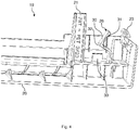
- the Fig. 1 shows a schematic perspective view of an embodiment of a household cooking appliance 1.
- the household cooking appliance 1 is preferably an oven, an oven with steam cooking function, a microwave combination oven or the like.
- the household cooking appliance 1 has an oven muffle, muffle or a cooking space 2 which can be closed with the aid of a door 3.
- the cooking space 2 can be arranged inside a housing of the household cooking appliance 1.
- the door is in the Fig. 1 shown in a closed position.
- the door 3 can be closed or opened by pivoting about a pivot axis provided at a lower end of the door 3.
- the door 3 can be hinged on the side of the cooking space 2.
- the door 3 can be arranged on a baking cart which can be pulled out of the cooking space 2.
- a handle 5 can be provided on an upper section or an upper edge 4 of the door 3.
- the cooking chamber 2 has a base 6, a ceiling 7 arranged opposite the base 6, a rear wall 8 arranged opposite the closed door 3 and two side walls 9, 10 arranged opposite one another.
- the cooking space 2 is preferably cuboid or cube-shaped.
- the cooking space 2 can be made from a metal material, in particular from a steel sheet.
- the household cooking appliance 1 further comprises control knobs 12, 13 provided on a control panel 11.
- the control knobs 12, 13 can be rotatable, for example.
- a control device 14, shown only schematically, for controlling the household cooking appliance 1 can be provided on the back of the control panel 11, a control device 14, shown only schematically, for controlling the household cooking appliance 1 can be provided.
- the control device 14 can be a regulating and / or control device.
- a display 15 can also be provided on the control panel 11. With the help of the display 15, an operating state of the household cooking appliance 1 can be displayed. For example, a temperature set using one of the operating knobs 12, 13 can be displayed using the display 15.
- the door 3 also has an outer pane 16 and one in the Fig. 1 inner pane, not shown.
- the outer pane 16 and the inner pane are arranged parallel to one another and spaced apart from one another.
- a first door profile 17 and a second door profile 18 are arranged between the outer pane 16 and the inner pane.
- the door profiles 17, 18 run parallel to a z-direction z of the household cooking appliance 1.
- the door profiles 17, 18 are firmly connected to the outer pane 16, for example glued.
- the door profiles 17, 18 are positioned at a distance from one another and parallel to one another.
- the door profiles 17, 18 are preferably made of a plastic material, but can also be designed as steel profiles.
- the door 3 further includes a removable and provided on the upper edge 4 end panel 19, which in the 2 to 4 is shown.
- the end panel 19 can also be referred to as a top panel and closes off an intermediate space provided between the outer pane 16 and the inner pane, that is, in the z direction z.
- the end panel 19 is preferably designed as a one-piece plastic component, in particular as a one-piece plastic injection molded component. As a result, the end panel 19 can be inexpensively manufactured in large numbers.
- a mixture of polybutylene terephthalate (PBT) and polyethylene terephthalate (PET) with a glass fiber filling is used as the material for the end panel 19.
- the material used can be filled with 20% glass fibers.
- the end panel 19 has a strip-shaped base section 20.
- Strip-shaped insertion aids 21, 22, in particular a first insertion aid 21 and a second insertion aid 22, are provided on both sides of the base section 20.
- the end panel 19 is guided to the door 3 during assembly and disassembly.
- the insertion aids 21, 22 can be guided in the z-direction z on the door profiles 17, 18.
- the end panel 19 comprises a spring-elastic deformable first snap hook 23 and a spring-elastic deformable second snap hook 24.
- the snap hooks 23, 24 are made in one piece with the base section 20.
- Each snap hook 23, 24 is assigned to one of the door profiles 17, 18.
- each door profile 17, 18 includes one in the Fig. 5 and 6 shown engagement section 25, in particular an undercut, which the respective snap hook 23, 24 can engage behind in a form-fitting manner.
- a positive connection is created by the interlocking or engaging of at least two connection partners, in this case the respective snap hook 23, 24 and the engagement section 25 assigned to it.
- a first spring element 26 and a second spring element 27 are arranged between the snap hooks 23, 24 and the insertion aids 21, 22.
- the spring elements 26, 27 are integrally formed with the base portion 20.
- the spring elements 26, 27 are resiliently deformable.
- the spring elements 26, 27 are L-shaped in the top view. Each spring element 26, 27 has a long leg 30 and a short leg 31. The legs 30, 31 are connected to one another at a contact section 32. When the spring elements 26, 27 are resiliently deformed, the short leg 31 is preferably deformed.
- the end panel 19 also has a stop section 33 arranged between the insertion aids 21, 22 and the spring elements 26, 27. Each stop section 33 is set up to rest on a respective upper edge 34 of the door profiles 17, 18. The contact section 32 is set up to slide on a corresponding contact surface 35 of the respective door profile 17, 18.
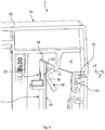
- the functionality of the end panel 19 is described below with reference to FIG Fig. 5 and 6 explained.
- the end panel 19 is, as in the Fig. 5 shown, with the door 3 open from the top, in the z-direction z, plugged onto the two door profiles 17, 18.
- the end panel 19 is from a disassembly state D, in which the end panel 19 is out of positive engagement with the door profiles 17, 18, in one in the Fig. 6 Assembly state shown M spent, in which the end panel 19 is in positive engagement with the door profiles 17, 18.
- the snap hooks 23, 24 of the end panel 19 snap into the door profile 17, 18 assigned to them.
- the snap hooks 23, 24 snap behind the respective engagement section 25 of the corresponding door profile 17, 18.
- the engagement section 25 can also be designed as an opening provided in the respective door profile 17, 18 or as a bore.
- the spring elements 26, 27 are shaped in such a way that the spring elements 26, 27 are resiliently deformed when the end panel 19 is fitted onto the door profiles 17, 18.
- the respective contact section 32 slides on the corresponding contact surface 35 of the corresponding door profile 17, 18.
- the contact surfaces 35 cooperate with the spring elements 26, 27 such that the spring elements 26, 27 are deformed when the end panel 19 is moved from the disassembled state D to the assembled state M from an undeformed state Z1 to a deformed state Z2.
- the spring elements 26, 27 are shaped in such a way that they deform in the x-direction x when the end panel 19 is mounted on the door profiles 17, 18 and slide easily over the contact surfaces 35 of the door profiles 17, 18. As a result, the spring elements 26, 27 in the assembled state M are under tension and center the end panel 19 between the door profiles 17, 18. "Centering" means that with the aid of the spring preload of the spring elements 26, 27 the end panel 19 or the base section 20 of the end panel 19 is arranged centrally between the two door profiles 17, 18. Furthermore, the spring elements 26, 27 allow a secure and firm fit of the end panel 19 on the door profiles 17, 18 due to their pretension.
- the end panel 19 can thus be averaged even with large adhesive tolerances of the door profiles 17, 18 and the component tolerances of the end panel 19 on the door 3 will. In this way, an attractive look can be achieved. However, there is still good haptics, since the end panel 19 cannot wobble.
- the spring elements 26, 27 each designed as a curved long tab, which produces their spring action over the length and wall thickness of the tab, that is, the length of the legs 30, 31.
- the spring action can be adjusted by varying the geometry of the spring elements 26, 27.
- the spring elements 26, 27 can also have any other geometry that is set up to center or center the end panel 19 between the door profiles 17, 18. This is possible as long as the spring elements 26, 27 exert a spring force on the door profiles 17, 18.
- An alternative way of adapting the spring action is to provide slots in the spring elements 26, 27 or by changing the wall thicknesses of the legs 30, 31.
- the end panel 19 can advantageously be produced in one piece with the spring elements 26, 27, in particular in one piece.
- “in one piece” is to be understood to mean that the end panel 19 and the spring elements 26, 27 are connected to one another in one piece.
- the end panel 19 and the spring elements 26, 27 are made of one piece of material, that is to say from the same material.
- This one-piece solution means that there are no additional parts and assembly costs.
- Another advantage of the end cover 19 compared to known end covers is the easy assembly and disassembly both in production and at the customer.
- the tolerance compensation created by the spring elements 26, 27 permits greater tolerances in the manufacture of the components and at the same time leads to an improved appearance and feel of the door 3 at the customer.
Landscapes
- Engineering & Computer Science (AREA)
- Mechanical Engineering (AREA)
- General Engineering & Computer Science (AREA)
- Chemical & Material Sciences (AREA)
- Combustion & Propulsion (AREA)
- Electromagnetism (AREA)
- Physics & Mathematics (AREA)
- Civil Engineering (AREA)
- Structural Engineering (AREA)
- Food Science & Technology (AREA)
- Electric Ovens (AREA)
- Control And Other Processes For Unpacking Of Materials (AREA)
- General Preparation And Processing Of Foods (AREA)
- Cookers (AREA)
- Assembled Shelves (AREA)
Description
- Die vorliegende Erfindung betrifft ein Haushaltsgargerät.
- Ein Haushaltsgargerät, insbesondere ein Backofen, kann einen beheizbaren Garraum aufweisen, der mit Hilfe einer Tür verschließbar ist. Um eine derartige Tür reinigen zu können, ist es vorteilhaft, wenn diese von einem Benutzer einfach zerlegbar und wieder montierbar ist.
- Die
DE 10 2010 013 903 A1 beschreibt eine Ofentüre umfassend wenigstens eine senkrecht angeordnete Türplatte, wobei an dieser Türplatte in deren rechten und linken Seitenbereichen oder -kanten ein erstes und ein zweites vertikal angeordnetes Türrahmenteil oder Türsäulenteil angeordnet sind. Die Türplatte wird von oben an deren Oberkante durch ein Türabdeckteil abgedeckt. Das Türabdeckteil umfasst einen Dorn oder einen Vorsprung, der an einem ersten Seitenbereich des Türabdeckteils angeordnet ist, wobei dieser Dorn oder Vorsprung derart ausgebildet ist, dass er in eine entsprechende Aussparung, welche an den ersten Türrahmenteil oder Türsäulenteil angeordnet ist, eingreifen kann. Das Türabdeckteil umfasst ferner ein Mittel zum Herstellen einer Schnappverbindung im Seitenbereich des Türabdeckteiles, wobei dieses Mittel derart ausgestaltet ist, dass es in eine Aussparung oder einen Hintergriff am zweiten Türrahmenteil oder Türsäulenteil im Wege einer Schnappverbindung eingreifen kann. - Die
DE 10 2012 213 126 A1 zeigt eine Tür für ein Haushaltsgerät mit einer flächigen Frontabdeckung, die eine Rückseite aufweist, an welcher zumindest ein Türprofil angeordnet ist, und mit einer oberen Türabdeckung, die mit dem Türprofil verrastend verbindbar ist, wobei zumindest ein Vorspannelement ausgebildet ist, durch welches ein Rastelement der Türabdeckung in der in einer Rastaufnahme im Türprofil verrasteten Position an das Türprofil angedrückt ist. - Die
EP 2 400 226 A1 beschreibt eine Tür für ein Haushaltsgargerät. Die Tür umfasst eine Außenscheibe, an der zwei Türprofile befestigt sind. An einer Oberkante der Tür ist eine Abschlussblende vorgesehen, die mit den Türprofilen verbunden ist. - Die
EP 2 901 085 A1 zeigt eine Tür für ein Haushaltsgerät, mit einer ersten Türscheibe und einer dazu beabstandet angeordneten zweiten Türscheibe, und einer Blende, die als zumindest bereichsweise Abdeckung von Rändern der Türscheiben angeordnet ist, wobei in die Blende eine Lagerungseinrichtung zum Lagern der Türscheiben zueinander integriert ist. - Die
EP 1 867 927 A2 beschreibt eine Tür zum Verschließen der Beschickungsöffnung eines Garraums eines Garofens, insbesondere eines Haushaltsgarofens, umfassend eine Außenscheibe, wenigstens eine Innenscheibe, wenigstens ein Halteelement zum Halten der wenigstens einen Innenscheibe, wenigstens ein Abdeckelement zum Abdecken des Halteelements, wobei das wenigstens eine Halteelement und wenigstens ein Abdeckelement separat hergestellt und dann miteinander zu einer Baugruppe verbunden sind, wobei zwischen dem wenigstens einen Abdeckelement und dem wenigstens einen Halteelement ein Luftführungskanal, insbesondere ein Luftausblaskanal, ausgebildet ist und wobei die Baugruppe die obere Einfassung der Türe ist und/oder im oberen Bereich der Türe angeordnet ist. - Die
EP 1 172 614 A1 zeigt eine Tür für ein Haushaltsgerät, insbesondere einen Haushaltsgarofen, mit einer Außenscheibe, wenigstens zwei mit der Außenscheibe verbundenen Trägerelementen und wenigstens zwei Halteelementen mit jeweils wenigstens einem Halteabschnitt für wenigstens eine Innenscheibe, wobei die Halteelemente an dem jeweiligen Trägerelement mittels wenigstens einer Rast- oder Schnappverbindung befestigt sind, wobei jede Rast- oder Schnappverbindung mit einer definierten Ausrichtung des oder der ineinandergreifenden Rast- oder Schnappelemente und Rast- oder Schnappaufnahmen unter einem Winkel ungleich 90° bezogen auf die Längsachse eines Trägerelements ausgebildet ist. - Die
DE 10 2005 037 020 A1 beschreibt eine Vorrichtung mit einer Haushaltsgerätetürträgereinheit, die wenigstens zwei Leisteneinheiten aufweist. Um verbesserte Montageeigenschaften bereitzustellen, ist die Haushaltsgerätetürträgereinheit zu einer einen Rahmen bildenden Montageeinheit zusammenführbar, die zur Montage an einer Haushaltsgerätetürfronteinheit vorgesehen ist. - Vor diesem Hintergrund besteht eine Aufgabe der vorliegenden Erfindung darin, ein verbessertes Haushaltsgargerät zur Verfügung zu stellen.
- Demgemäß wird ein Haushaltsgargerät mit einem Garraum und einer Tür zum Verschließen des Garraums vorgeschlagen. Die Tür weist zwei voneinander beabstandet angeordnete Türprofile und eine an einer Oberkante der Tür vorgesehene Abschlussblende auf, die mit den Türprofilen formschlüssig verbunden ist, wobei die Abschlussblende zwei Federelemente aufweist, wobei jedes Federelement einem der Türprofile zugeordnet ist und dieses kontaktiert, wobei die Federelemente federelastisch verformbar sind, um die Abschlussblende zwischen den Türprofilen zu zentrieren, wobei die Abschlussblende und die Federelemente einteilig ausgebildet sind, wobei die Abschlussblende zwei federelastisch verformbare Schnapphaken aufweist, die dazu eingerichtet sind, formschlüssig in die Türprofile einzugreifen, und wobei die Schnapphaken und die Federelemente voneinander getrennte Abschnitte der Abschlussblende sind.
- Dadurch, dass die Federelemente die Abschlussblende zwischen den Türprofilen zentrieren, ist eine selbsttätige Positionierung der Bauteile zueinander möglich, welche bei jedem erneutem Zusammenbau die richtige Position der Bauteile zueinander sicherstellt und die Toleranzen der Bauteile ausgleichen kann. Es ist keine Relativbewegung der Abschlussblende zu den Türprofilen möglich, wodurch bei einer Bewegung der Tür keine störenden Geräusche erzeugt werden und ein Wackeln oder Klappern der Abschlussblende verhindert wird. Es ist somit ein einfacher und wiederholbarer Toleranzausgleich möglich. Dadurch, dass die Federelemente einteilig mit der Abschlussblende ausgebildet ist, kann auf zusätzliche und damit verlierbare Bauteile verzichtet werden. Zudem können die Abschlussblende und die Federelemente aus dem gleichen Werkstoff gebildet sein. Durch die einteilige Lösung fallen keine zusätzlichen Teile- und Montagekosten an. Ein weiterer Vorteil ist die leichtgängige Montage und Demontage sowohl in der Fertigung als auch beim Kunden. Der durch die Federelemente geschaffene Toleranzausgleich erlaubt größere Toleranzen in der Herstellung der Bauteile und führt gleichzeitig zu einer verbesserten Optik und Haptik der Tür beim Kunden.
- Die Tür weist vorzugsweise mehrere Scheiben, insbesondere eine Frontscheibe oder Außenscheibe, eine Innenscheibe und mehrere zwischen der Außenscheibe und der Innenscheibe angeordnete Zwischenscheiben auf, die bevorzugt aus einem Glaswerkstoff gefertigt sind. Die Türprofile können fest mit der Außenscheibe verbunden, beispielsweise mit dieser verklebt, sein. Die Türprofile sind jeweils beidseits randseitig an der Tür vorgesehen. Die Türprofile sind vorzugsweise parallel zueinander und beabstandet voneinander angeordnet, Die Türprofile können beispielsweise aus Stahl oder einem Kunststoffmaterial gefertigt sein. Eine formschlüssige Verbindung entsteht durch das Ineinander- oder Hintergreifen von mindestens zwei Verbindungspartnern, hier der Abschlussblende und den Türprofilen. Unter "Zentrieren" ist vorliegend zu verstehen, dass die Abschlussblende beziehungsweise ein Basisabschnitt der Abschlussblende mittig zu oder zwischen den Türprofilen angeordnet wird. Unter "einteilig" ist vorliegend zu verstehen, dass die Abschlussblende und die Federelemente ein gemeinsames Bauteil bilden und keine voneinander getrennten Bauteile sind. Der Begriff "einteilig" kann durch den Begriff "einstückig" ersetzt werden. Insbesondere können die Federelemente auch materialeinstückig mit der Abschlussblende ausgebildet sein. Das heißt, die Abschlussblende und die Federelemente sind aus demselben Material gefertigt. Vorzugsweise ist die Abschlussblende aus einem Kunststoffmaterial gefertigt. Bevorzugt ist die Abschlussblende ein Kunststoffspritzgussbauteil. Hierdurch kann die Abschlussblende kostengünstig in großen Stückzahlen hergestellt werden.
- Die Abschlussblende weist zwei federelastisch verformbare Schnapphaken auf, die dazu eingerichtet sind, formschlüssig in die Türprofile einzugreifen.
- Insbesondere ist jedem Türprofil ein derartiger Schnapphaken zugeordnet. Die Abschlussblende ist hierdurch werkzeuglos demontierbar und montierbar. Die Schnapphaken sind insbesondere nicht identisch mit den Federelementen. Das heißt, die Schnapphaken und die Federelemente sind voneinander getrennte Abschnitte der Abschlussblende.
- Gemäß einer weiteren Ausführungsform sind die Abschlussblende und die Schnapphaken einteilig ausgebildet.
- Insbesondere sind die Abschlussblende und die Schnapphaken materialeinstückig ausgeführt.
- Gemäß einer weiteren Ausführungsform weist jedes Türprofil einen Eingriffsabschnitt, insbesondere einen Hinterschnitt, auf, in den einer der Schnapphaken formschlüssig eingreift.
- Insbesondere ist jedem Schnapphaken ein derartiger Eingriffsabschnitt zugeordnet. Der Eingriffsabschnitt kann auch als in dem jeweiligen Türprofil ausgebildeter Durchbruch oder als eine Bohrung ausgebildet sein.
- Gemäß einer weiteren Ausführungsform ist die Abschlussblende mit Hilfe eines Aufsteckens derselben auf die Türprofile von einem Demontagezustand, in dem die Abschlussblende außer formschlüssigem Eingriff mit den Türprofilen ist, in einen Montagezustand, in dem die Abschlussblende in formschlüssigem Eingriff mit den Türprofilen ist, verbringbar.
- Zum Verbringen der Abschlussblende von dem Demontagezustand in den Montagezustand wird die Abschlussblende linear zu und linear entlang der Türprofile bewegt.
- Gemäß einer weiteren Ausführungsform weisen die Federelemente jeweils einen Kontaktabschnitt auf, der dazu eingerichtet ist, bei einem Verbringen der Abschlussblende von dem Demontagezustand in den Montagezustand oder umgekehrt auf einer korrespondierenden Kontaktfläche des jeweiligen Türprofils abzugleiten.
- Insbesondere ist jedem Federelement eine derartige Kontaktfläche zugeordnet. Bevorzugt verformen sich die Federelemente bei dem Verbringen der Abschlussblende von dem Montagezustand in den Montagezustand oder umgekehrt federelastisch und gleiten dabei leichtgängig auf den Kontaktflächen ab.
- Gemäß einer weiteren Ausführungsform wirken die Kontaktflächen so mit den Federelementen zusammen, dass die Federelemente bei einem Verbringen der Abschlussblende von dem Demontagezustand in den Montagezustand von einem unverformten Zustand in einen verformten Zustand verformbar sind.
- Bevorzugt wirken die Kontaktflächen auch so mit den Federelementen zusammen, dass sich die Federelemente bei einem Verbringen der Abschlussblende von dem Montagezustand in den Demontagezustand selbsttätig von dem verformten Zustand in den unverformten Zustand verformen.
- Gemäß einer weiteren Ausführungsform weist jedes Federelement einen ersten Schenkel und einen mit Hilfe des Kontaktabschnitts mit dem ersten Schenkel verbundenen zweiten Schenkel auf.
- Insbesondere sind die Federelemente L-förmig ausgebildet. Bevorzugt sind die Federelemente jeweils als eine gebogene lange Lasche ausgebildet, welche ihre Federwirkung über die Länge und die Wandstärke der Lasche erzeugt. Durch Variation dieser Faktoren kann die Federwirkung auf den jeweiligen Anwendungsfall angepasst werden. Die Federelemente können auch in jeder anderen Geometrie ausgeführt sein, solange diese eine federnde Wirkung auf die Türprofile ausübt. Die Federwirkung kann auch durch Schlitze im jeweiligen Federelement oder durch dünne Wandstärken eingestellt werden.
- Gemäß einer weiteren Ausführungsform weist die Abschlussblende zumindest eine Einführhilfe auf, mit deren Hilfe die Abschlussblende bei einem Verbringen der Abschlussblende von dem Demontagezustand in den Montagezustand linear an den Türprofilen geführt ist.
- Vorzugsweise sind zumindest zwei Einführhilfen vorgesehen. Mit Hilfe der Einführhilfen ist eine einfache Montage möglich und eine Fehlmontage wird zuverlässig verhindert. Bevorzugt sind die Einführhilfen einteilig mit der Abschlussblende ausgebildet. Die Einführhilfen sind nicht identisch mit den Federelementen und den Schnapphaken. Das heißt, die Einführhilfen, die Schnapphaken und die Federelemente sind voneinander getrennte Abschnitte der Abschlussblende. Bevorzugt ist jeweils ein Federelement zwischen einem Schnapphaken und einer Einführhilfe angeordnet.
- Gemäß einer weiteren Ausführungsform weist die Abschlussblende zumindest einen Anschlagabschnitt auf, der in dem Montagezustand eine korrespondierende Oberkante des jeweiligen Türprofils kontaktiert.
- Bevorzugt sind zwei derartige Anschlagabschnitte vorgesehen, wobei jedem Türprofil ein Anschlagabschnitt zugeordnet ist. Mit Hilfe der Anschlagabschnitte ist eine reproduzierbare Positionierung der Abschlussblende relativ zu den Türprofilen in einer Richtung entlang den Türprofilen möglich.
- Weitere mögliche Implementierungen des Haushaltsgargeräts umfassen auch nicht explizit genannte Kombinationen von zuvor oder im Folgenden bezüglich der Ausführungsbeispiele beschriebenen Merkmale oder Ausführungsformen. Dabei wird der Fachmann auch Einzelaspekte als Verbesserungen oder Ergänzungen zu der jeweiligen Grundform des Haushaltsgargeräts hinzufügen.
- Weitere vorteilhafte Ausgestaltungen und Aspekte des Haushaltsgargeräts sind Gegenstand der Unteransprüche sowie der im Folgenden beschriebenen Ausführungsbeispiele des Haushaltsgargeräts. Im Weiteren wird das Haushaltsgargerät anhand von bevorzugten Ausführungsformen unter Bezugnahme auf die beigelegten Figuren näher erläutert.
- Fig. 1
- zeigt eine schematische perspektivische Ansicht einer Ausführungsform eines Haushaltsgargeräts;
- Fig. 2
- zeigt eine schematische perspektivische Ansicht einer Ausführungsform einer Abschlussblende für eine Tür des Haushaltsgargeräts gemäß
Fig. 1 ; - Fig. 3
- zeigt eine weitere schematische perspektivische Ansicht der Abschlussblende gemäß
Fig. 2 ; - Fig. 4
- zeigt eine weitere schematische perspektivische Ansicht der Abschlussblende gemäß
Fig. 2 ; - Fig. 5
- zeigt eine schematische perspektivische Ansicht einer Ausführungsform einer Tür für das Haushaltsgargerät gemäß
Fig. 1 ; und - Fig. 6
- zeigt eine weitere schematische perspektivische Ansicht der Tür gemäß
Fig. 5 . - In den Figuren sind gleiche oder funktionsgleiche Elemente mit denselben Bezugszeichen versehen worden, sofern nichts anderes angegeben ist.
- Die
Fig. 1 zeigt eine schematische perspektivische Ansicht einer Ausführungsform eines Haushaltsgargeräts 1. Das Haushaltsgargerät 1 ist vorzugsweise ein Backofen, ein Backofen mit Dampfgarfunktion, ein Mikrowellen-Kombinationsbackofen oder dergleichen. Das Haushaltsgargerät 1 weist eine Backofenmuffel, Muffel oder einen Garraum 2 auf, der mit Hilfe einer Tür 3 verschließbar ist. Der Garraum 2 kann im Inneren eines Gehäuses des Haushaltsgargeräts 1 angeordnet sein. Die Tür ist in derFig. 1 in einer geschlossenen Stellung dargestellt. Durch ein Schwenken um eine an einem unteren Ende der Tür 3 vorgesehene Schwenkachse kann die Tür 3 geschlossen oder geöffnet werden. Alternativ kann die Tür 3 seitlich an dem Garraum 2 angeschlagen sein. Weiterhin kann die Tür 3 an einem aus dem Garraum 2 herausziehbaren Backwagen angeordnet sein. An einem oberen Abschnitt oder einer Oberkante 4 der Tür 3 kann ein Griff 5 vorgesehen sein. - Der Garraum 2 weist einen Boden 6, eine dem Boden 6 gegenüberliegend angeordnete Decke 7, eine der geschlossenen Tür 3 gegenüberliegend angeordnete Rückwand 8 und zwei einander gegenüberliegend angeordnete Seitenwände 9, 10 auf. Der Garraum 2 ist vorzugsweise quader- oder würfelförmig. Der Garraum 2 kann aus einem Metallwerkstoff, insbesondere aus einem Stahlblech, gefertigt sein.
- Das Haushaltsgargeräts 1 umfasst weiterhin an einer Bedienblende 11 vorgesehene Bedienknäufe 12, 13. Die Bedienknäufe 12, 13 können beispielsweise drehbar sein. Rückseitig an der Bedienblende 11 kann eine nur schematisch gezeigte Steuereinrichtung 14 zum Steuern des Haushaltsgargeräts 1 vorgesehen sein. Die Steuereinrichtung 14 kann eine Regel- und/oder Steuereinrichtung sein. An der Bedienblende 11 kann weiterhin ein Anzeigedisplay 15 vorgesehen sein. Mit Hilfe des Anzeigedisplays 15 kann ein Betriebszustand des Haushaltsgargeräts 1 angezeigt werden. Beispielsweise kann mit Hilfe des Anzeigedisplays 15 eine mit Hilfe eines der Bedienknäufe 12, 13 eingestellte Temperatur angezeigt werden.
- Die Tür 3 weist weiterhin eine Außenscheibe 16 sowie eine in der
Fig. 1 nicht gezeigte Innenscheibe auf. Die Außenscheibe 16 und die Innenscheibe sind parallel zueinander und beabstandet voneinander angeordnet. Zwischen der Außenscheibe 16 und der Innenscheibe sind ein erstes Türprofil 17 sowie ein zweites Türprofil 18 angeordnet. Die Türprofile 17, 18 verlaufen in einem geschlossenen Zustand der Tür 3 parallel zu einer z-Richtung z des Haushaltsgargeräts 1. In derFig. 1 sind weiterhin noch eine x-Richtung x sowie eine y-Richtung y gezeigt. Die Türprofile 17, 18 sind fest mit der Außenscheibe 16 verbunden, beispielsweise verklebt. Die Türprofile 17, 18 sind beabstandet voneinander und parallel zueinander positioniert. Die Türprofile 17, 18 sind vorzugsweise aus einem Kunststoffmaterial gefertigt, können aber auch als Stahlprofile ausgebildet sein. - Die Tür 3 umfasst weiterhin eine an der Oberkante 4 vorgesehene und abnehmbare Abschlussblende 19, die in den
Fig. 2 bis 4 gezeigt ist. Die Abschlussblende 19 kann auch als Topblende bezeichnet werden und schließt einen zwischen der Außenscheibe 16 und der Innenscheibe vorgesehenen Zwischenraum nach oben hin, das heißt, in der z-Richtung z ab. Die Abschlussblende 19 ist vorzugsweise als einstückiges Kunststoffbauteil, insbesondere als einstückiges Kunststoffspritzgussbauteil, ausgebildet. Hierdurch kann die Abschlussblende 19 kostengünstig in großen Stückzahlen hergestellt werden. Als Material für die Abschlussblende 19 kommt beispielsweise ein Gemisch aus Polybutylenterephthalat (PBT) und Polyethylenterephthalat (PET) mit einer Glasfaserfüllung zum Einsatz. Beispielsweise kann das verwendete Material mit 20% Glasfasern gefüllt sein. - Die Abschlussblende 19 weist einen leistenförmigen Basisabschnitt 20 auf. Beidseitig an dem Basisabschnitt 20 sind leistenförmige Einführhilfen 21, 22, insbesondere eine erste Einführhilfe 21 sowie eine zweite Einführhilfe 22, vorgesehen. Mit Hilfe der Einführhilfen 21, 22 ist die Abschlussblende 19 bei der Montage und Demontage derselben an der Tür 3 geführt. Beispielsweise können die Einführhilfen 21, 22 in der z-Richtung z an den Türprofilen 17, 18 geführt sein.
- Weiterhin umfasst die Abschlussblende 19 einen federelastisch verformbaren ersten Schnapphaken 23 sowie einen federelastisch verformbaren zweiten Schnapphaken 24. Die Schnapphaken 23, 24 sind materialeinstückig mit dem Basisabschnitt 20 ausgebildet. Jeder Schnapphaken 23, 24 ist einem der Türprofile 17, 18 zugeordnet. Beispielsweise umfasst jedes Türprofil 17, 18 einen in den
Fig. 5 und6 gezeigten Eingriffsabschnitt 25, insbesondere einen Hinterschnitt, den der jeweilige Schnapphaken 23, 24 formschlüssig hintergreifen kann. Eine formschlüssige Verbindung entsteht durch das Ineinander- oder Hintergreifen von mindestens zwei Verbindungspartnern, in diesem Fall dem jeweiligen Schnapphaken 23, 24 und dem ihm zugeordneten Eingriffsabschnitt 25. - Zwischen den Schnapphaken 23, 24 und den Einführhilfen 21, 22 sind ein erstes Federelement 26 und ein zweites Federelement 27 angeordnet. Die Federelemente 26, 27 sind materialeinstückig mit dem Basisabschnitt 20 ausgebildet. Die Federelemente 26, 27 sind federelastisch verformbar. Zwischen den Einführhilfen 21, 22 sind ferner zwei voneinander beabstandet angeordnete weitere Einführhilfen 28, 29 vorgesehen.
- Die Federelemente 26, 27 sind in der Aufsicht L-förmig ausgebildet. Jedes Federelement 26, 27 weist einen langen Schenkel 30 sowie einen kurzen Schenkel 31 auf. Die Schenkel 30, 31 sind an einem Kontaktabschnitt 32 miteinander verbunden. Bei einem federelastischen Verformen der Federelemente 26, 27 verformt sich bevorzugt der kurze Schenkel 31. Die Abschlussblende 19 weist weiterhin jeweils einen zwischen den Einführhilfen 21, 22 und den Federelementen 26, 27 angeordneten Anschlagabschnitt 33 auf. Jeder Anschlagabschnitt 33 ist dazu eingerichtet, auf einer jeweiligen Oberkante 34 der Türprofile 17, 18 aufzuliegen. Der Kontaktabschnitt 32 ist dazu eingerichtet, auf einer korrespondierenden Kontaktfläche 35 des jeweiligen Türprofils 17, 18 abzugleiten.
- Die Funktionalität der Abschlussblende 19 wird nachfolgend mit Bezug auf die
Fig. 5 und6 erläutert. Die Abschlussblende 19 wird, wie in derFig. 5 gezeigt, bei geöffneter Tür 3 von schräg oben im Wesentlichen in der z-Richtung z auf die beiden Türprofile 17, 18 aufgesteckt. Dabei wird die Abschlussblende 19 von einem Demontagezustand D, in dem die Abschlussblende 19 außer formschlüssigem Eingriff mit den Türprofilen 17, 18 ist, in einen in derFig. 6 gezeigten Montagezustand M verbracht, in dem die Abschlussblende 19 in formschlüssigem Eingriff mit den Türprofilen 17, 18 ist. Dazu schnappen die Schnapphaken 23, 24 der Abschlussblende 19 in dem ihnen zugeordneten Türprofil 17, 18 ein. Insbesondere schnappen die Schnapphaken 23, 24 hinter den jeweiligen Eingriffsabschnitt 25 des entsprechenden Türprofils 17, 18 ein. Der Eingriffsabschnitt 25 kann auch als in dem jeweiligen Türprofil 17, 18 vorgesehener Durchbruch oder als Bohrung ausgebildet sein. - Bezüglich der x-Richtung x sind die Federelemente 26, 27 so ausgeformt, dass die Federelemente 26, 27 beim Aufstecken der Abschlussblende 19 auf die Türprofile 17, 18 federelastisch verformt werden. Dabei gleitet der jeweilige Kontaktabschnitt 32 auf der entsprechenden Kontaktfläche 35 des entsprechenden Türprofils 17, 18 ab. Hierbei wirken die Kontaktflächen 35 so mit den Federelementen 26, 27 zusammen, dass die Federelemente 26, 27 bei dem Verbringen der Abschlussblende 19 von dem Demontagezustand D in den Montagezustand M von einem unverformten Zustand Z1 in einen verformten Zustand Z2 verformt werden.
- Die Federelemente 26, 27 sind dabei so ausgeformt, dass sie sich bei der Montage der Abschlussblende 19 an den Türprofilen 17, 18 in der x-Richtung x verformen und leichtgängig über die Kontaktflächen 35 der Türprofile 17, 18 rutschen. Hierdurch sind die Federelemente 26, 27 in dem Montagezustand M unter Spannung und zentrieren die Abschlussblende 19 zwischen den Türprofilen 17, 18. Unter "Zentrieren" ist dabei zu verstehen, dass mit Hilfe der Federvorspannung der Federelemente 26, 27 die Abschlussblende 19 beziehungsweise der Basisabschnitt 20 der Abschlussblende 19 mittig zwischen den beiden Türprofilen 17, 18 angeordnet ist. Weiterhin ermöglichen die Federelemente 26, 27 aufgrund ihrer Vorspannung einen sicheren und festen Sitz der Abschlussblende 19 auf den Türprofilen 17, 18. Die Abschlussblende 19 kann so auch bei großen Klebetoleranzen der Türprofile 17, 18 und der Bauteiltoleranzen der Abschlussblende 19 auf der Tür 3 ausgemittelt werden. Hierdurch kann eine ansprechende Optik verwirklich werden. Weiterhin ergibt sich jedoch eine gute Haptik, da die Abschlussblende 19 nicht wackeln kann.
- Bei der Ausführungsform der Abschlussblende 19 gemäß den
Fig. 2 bis 6 sind die Federelemente 26, 27 jeweils als gebogene lange Lasche ausgeführt, welche ihre Federwirkung über die Länge und die Wandstärke der Lasche, das heißt, die Länge der Schenkel 30, 31 erzeugt. Durch Variation der Geometrie der Federelemente 26, 27 kann die Federwirkung angepasst werden. Die Federelemente 26, 27 können auch jede andere beliebige Geometrie aufweisen, die dazu eingerichtet ist, die Abschlussblende 19 zwischen den Türprofilen 17, 18 zu zentrieren oder auszumitteln. Dies ist so lange möglich, solange die Federelemente 26, 27 eine Federkraft auf die Türprofile 17, 18 ausüben. Eine alternative Möglichkeit, die Federwirkung anzupassen, ist das Vorsehen von Schlitzen in den Federelementen 26, 27 oder durch eine Veränderung der Wandstärken der Schenkel 30, 31. - Vorteilhafterweise kann die Abschlussblende 19 mit den Federelementen 26, 27 einstückig, insbesondere materialeinstückig, hergestellt werden. Unter "einstückig" ist vorliegend zu verstehen, dass die Abschlussblende 19 und die Federelemente 26, 27 einteilig miteinander verbunden sind. Vorzugsweise sind die Abschlussblende 19 und die Federelemente 26, 27 materialeinstückig, das heißt, aus dem gleichen Werkstoff, ausgebildet. Durch diese materialeinstückige Lösung fallen keine zusätzlichen Teile- und Montagekosten an. Ein weiterer Vorteil der Abschlussblende 19 im Vergleich zu bekannten Abschlussblenden ist die leichtgängige Montage und Demontage sowohl in der Fertigung als auch beim Kunden. Der durch die Federelemente 26, 27 geschaffene Toleranzausgleich erlaubt größere Toleranzen in der Herstellung der Bauteile und führt gleichzeitig zu einer verbesserten Optik und Haptik der Tür 3 beim Kunden.
-
- 1
- Haushaltsgargerät
- 2
- Garraum
- 3
- Tür
- 4
- Oberkante
- 5
- Griff
- 6
- Boden
- 7
- Decke
- 8
- Rückwand
- 9
- Seitenwand
- 10
- Seitenwand
- 11
- Bedienblende
- 12
- Bedienknauf
- 13
- Bedienknauf
- 14
- Steuereinrichtung
- 15
- Anzeigedisplay
- 16
- Außenscheibe
- 17
- Türprofil
- 18
- Türprofil
- 19
- Abschlussblende
- 20
- Basisabschnitt
- 21
- Einführhilfe
- 22
- Einführhilfe
- 23
- Schnapphaken
- 24
- Schnapphaken
- 25
- Eingriffsabschnitt
- 26
- Federelement
- 27
- Federelement
- 28
- Einführhilfe
- 29
- Einführhilfe
- 30
- Schenkel
- 31
- Schenkel
- 32
- Kontaktabschnitt
- 33
- Anschlagabschnitt
- 34
- Oberkante
- 35
- Kontaktfläche
- D
- Demontagezustand
- M
- Montagezustand
- x
- x-Richtung
- y
- y-Richtung
- z
- z-Richtung
- Z1
- Zustand
- Z2
- Zustand
Claims (9)
- Haushaltsgargerät (1) mit einem Garraum (2) und einer Tür (3) zum Verschließen des Garraums (2), wobei die Tür (3) zwei voneinander beabstandet angeordnete Türprofile (17, 18) und eine an einer Oberkante (4) der Tür (3) vorgesehene Abschlussblende (19) aufweist, die mit den Türprofilen (17, 18) formschlüssig verbunden ist, wobei die Abschlussblende (19) zwei Federelemente (26, 27) aufweist, wobei jedes Federelement (26, 27) einem der Türprofile (17, 18) zugeordnet ist und dieses kontaktiert, wobei die Federelemente (26, 27) federelastisch verformbar sind, um die Abschlussblende (19) zwischen den Türprofilen (17, 18) zu zentrieren, wobei die Abschlussblende (19) und die Federelemente (26, 27) einteilig ausgebildet sind, dadurch gekennzeichnet, dass die Abschlussblende (19) zwei federelastisch verformbare Schnapphaken (23, 24) aufweist, die dazu eingerichtet sind, formschlüssig in die Türprofile (17, 18) einzugreifen, und wobei die Schnapphaken (23, 24) und die Federelemente (26, 27) voneinander getrennte Abschnitte der Abschlussblende (19) sind.
- Haushaltsgargerät nach Anspruch 1, dadurch gekennzeichnet, dass die Abschlussblende (19) und die Schnapphaken (23, 24) einteilig ausgebildet sind.
- Haushaltsgargerät nach Anspruch 1 oder 2, dadurch gekennzeichnet, dass jedes Türprofil (17, 18) einen Eingriffsabschnitt (25), insbesondere einen Hinterschnitt, aufweist, in den einer der Schnapphaken (23, 24) formschlüssig eingreift.
- Haushaltsgargerät nach einem der Ansprüche 1 - 3, dadurch gekennzeichnet, dass die Abschlussblende (19) mit Hilfe eines Aufsteckens derselben auf die Türprofile (17, 18) von einem Demontagezustand (D), in dem die Abschlussblende (19) außer formschlüssigem Eingriff mit den Türprofilen (17, 18) ist, in einen Montagezustand (M), in dem die Abschlussblende (19) in formschlüssigem Eingriff mit den Türprofilen (17, 18) ist, verbringbar ist.
- Haushaltsgargerät nach Anspruch 4, dadurch gekennzeichnet, dass die Federelemente (26, 27) jeweils einen Kontaktabschnitt (32) aufweisen, der dazu eingerichtet ist, bei einem Verbringen der Abschlussblende (19) von dem Demontagezustand (D) in den Montagezustand (M) oder umgekehrt auf einer korrespondierenden Kontaktfläche (35) des jeweiligen Türprofils (17, 18) abzugleiten.
- Haushaltsgargerät nach Anspruch 5, dadurch gekennzeichnet, dass die Kontaktflächen (35) so mit den Federelementen (26, 27) zusammenwirken, dass die Federelemente (26, 27) bei einem Verbringen der Abschlussblende (19) von dem Demontagezustand (D) in den Montagezustand (M) von einem unverformten Zustand (Z1) in einen verformten Zustand (Z2) verformbar sind.
- Haushaltsgargerät nach Anspruch 5 oder 6, dadurch gekennzeichnet, dass jedes Federelement (26, 27) einen ersten Schenkel (30) und einen mit Hilfe des Kontaktabschnitts (32) mit dem ersten Schenkel (30) verbundenen zweiten Schenkel (31) aufweist.
- Haushaltsgargerät nach einem der Ansprüche 4 - 7, dadurch gekennzeichnet, dass die Abschlussblende (19) zumindest eine Einführhilfe (21, 22) aufweist, mit deren Hilfe die Abschlussblende (19) bei einem Verbringen der Abschlussblende (19) von dem Demontagezustand (D) in den Montagezustand (M) linear an den Türprofilen (17, 18) geführt ist.
- Haushaltsgargerät nach einem der Ansprüche 4-8, dadurch gekennzeichnet, dass die Abschlussblende (19) zumindest einen Anschlagabschnitt (33) aufweist, der in dem Montagezustand (M) eine korrespondierende Oberkante (34) des jeweiligen Türprofils (17, 18) kontaktiert.
Priority Applications (1)
| Application Number | Priority Date | Filing Date | Title |
|---|---|---|---|
| PL17203472.0T PL3333489T5 (pl) | 2016-12-12 | 2017-11-24 | Urządzenie gospodarstwa domowego do obróbki termicznej |
Applications Claiming Priority (1)
| Application Number | Priority Date | Filing Date | Title |
|---|---|---|---|
| DE102016224743.3A DE102016224743A1 (de) | 2016-12-12 | 2016-12-12 | Haushaltsgargerät |
Publications (3)
| Publication Number | Publication Date |
|---|---|
| EP3333489A1 EP3333489A1 (de) | 2018-06-13 |
| EP3333489B1 true EP3333489B1 (de) | 2020-05-20 |
| EP3333489B2 EP3333489B2 (de) | 2023-02-22 |
Family
ID=60452508
Family Applications (1)
| Application Number | Title | Priority Date | Filing Date |
|---|---|---|---|
| EP17203472.0A Active EP3333489B2 (de) | 2016-12-12 | 2017-11-24 | Haushaltsgargerät |
Country Status (5)
| Country | Link |
|---|---|
| EP (1) | EP3333489B2 (de) |
| CN (1) | CN108209606A (de) |
| DE (1) | DE102016224743A1 (de) |
| ES (1) | ES2796657T5 (de) |
| PL (1) | PL3333489T5 (de) |
Cited By (1)
| Publication number | Priority date | Publication date | Assignee | Title |
|---|---|---|---|---|
| EP4150259A1 (de) * | 2020-05-11 | 2023-03-22 | BSH Hausgeräte GmbH | Anzeige- und bedienvorrichtung und haushaltsgerät |
Families Citing this family (5)
| Publication number | Priority date | Publication date | Assignee | Title |
|---|---|---|---|---|
| DE102018221069A1 (de) * | 2018-12-05 | 2020-06-10 | BSH Hausgeräte GmbH | Tür für ein Haushaltsgerät mit mechanisch gekippter Blende, sowie Haushaltsgerät und Verfahren zur Montage einer Blende für ein Scheibenpaket der Tür |
| TR201820666A2 (tr) * | 2018-12-27 | 2020-07-21 | Bsh Ev Aletleri San Ve Tic As | Ev ci̇hazi i̇çi̇n bi̇r kapi |
| EP4034814A4 (de) * | 2019-11-02 | 2023-06-07 | Femas Metal San. Ve Tic. A.S. | Haushaltsofen mit einer tür mit abnehmbarer haltekappe |
| DE102020209247A1 (de) | 2020-07-22 | 2022-01-27 | BSH Hausgeräte GmbH | Tür und Haushaltsgargerät |
| WO2023232091A1 (zh) * | 2022-06-01 | 2023-12-07 | 广东美的厨房电器制造有限公司 | 门体组件和烹饪器具 |
Citations (6)
| Publication number | Priority date | Publication date | Assignee | Title |
|---|---|---|---|---|
| WO2011120678A1 (de) | 2010-04-01 | 2011-10-06 | Electrolux Home Products Corporation N.V. | Ofentüre, sowie verfahren zum befestigen eines türabdeckteils |
| EP2386800A1 (de) | 2010-05-14 | 2011-11-16 | Electrolux Home Products Corporation N.V. | Tür für ein Haushaltsgerät |
| EP2400226A1 (de) | 2010-06-23 | 2011-12-28 | Vestel Beyaz Esya Sanayi Ve Ticaret A.S. | Tür einer Garvorrichtung |
| DE102012217355A1 (de) | 2012-09-26 | 2014-03-27 | BSH Bosch und Siemens Hausgeräte GmbH | Tür für ein Haushaltsgerät und Haushaltsgerät zum Zubereiten von Lebensmitteln mit einer Tür |
| WO2014102116A1 (en) | 2012-12-28 | 2014-07-03 | Arcelik Anonim Sirketi | A door comprising detachable panels and an oven wherein the door is used |
| EP2921782A2 (de) | 2014-03-19 | 2015-09-23 | BSH Hausgeräte GmbH | Tür für ein haushaltsgerät mit einer als hybrid-bauteil ausgebildeten abdeckung für zumindest eine türscheibe sowie haushaltsgerät mit einer derartigen tür |
Family Cites Families (7)
| Publication number | Priority date | Publication date | Assignee | Title |
|---|---|---|---|---|
| DE10033358C2 (de) * | 2000-07-08 | 2003-07-31 | Aeg Hausgeraete Gmbh | Tür für ein Haushaltsgerät, insbesondere einen Haushaltsgarofen |
| DE102005037020A1 (de) * | 2004-09-09 | 2006-03-16 | BSH Bosch und Siemens Hausgeräte GmbH | Vorrichtung mit einer Haushaltsgerätetürträgereinheit |
| DE102006027610A1 (de) * | 2006-06-13 | 2007-12-20 | Electrolux Home Products Corporation N.V. | Tür zum Verschließen der Beschickungsöffnung eines Garraums eines Garofens, insbesondere eines Haushaltsgarofens |
| EP2090832B1 (de) * | 2008-02-15 | 2013-06-12 | Electrolux Home Products Corporation N.V. | Türensystem zur Schließung einer Zufuhrvorrichtung zum Garraum eines Backofens |
| DE102012213126B4 (de) | 2012-07-26 | 2022-11-10 | BSH Hausgeräte GmbH | Tür für ein Haushaltsgerät mit einem Rastelement und einem Vorspannelement sowie Backofen mit einer derartigen Tür |
| US10145565B2 (en) * | 2014-04-08 | 2018-12-04 | Whirlpool Emea S.P.A. | Door for a domestic cooking oven |
| WO2015165499A1 (en) * | 2014-04-29 | 2015-11-05 | Arcelik Anonim Sirketi | Door with improved disassembly/reassembly for use in an oven |
-
2016
- 2016-12-12 DE DE102016224743.3A patent/DE102016224743A1/de not_active Withdrawn
-
2017
- 2017-11-24 ES ES17203472T patent/ES2796657T5/es active Active
- 2017-11-24 PL PL17203472.0T patent/PL3333489T5/pl unknown
- 2017-11-24 EP EP17203472.0A patent/EP3333489B2/de active Active
- 2017-12-11 CN CN201711309288.0A patent/CN108209606A/zh active Pending
Patent Citations (6)
| Publication number | Priority date | Publication date | Assignee | Title |
|---|---|---|---|---|
| WO2011120678A1 (de) | 2010-04-01 | 2011-10-06 | Electrolux Home Products Corporation N.V. | Ofentüre, sowie verfahren zum befestigen eines türabdeckteils |
| EP2386800A1 (de) | 2010-05-14 | 2011-11-16 | Electrolux Home Products Corporation N.V. | Tür für ein Haushaltsgerät |
| EP2400226A1 (de) | 2010-06-23 | 2011-12-28 | Vestel Beyaz Esya Sanayi Ve Ticaret A.S. | Tür einer Garvorrichtung |
| DE102012217355A1 (de) | 2012-09-26 | 2014-03-27 | BSH Bosch und Siemens Hausgeräte GmbH | Tür für ein Haushaltsgerät und Haushaltsgerät zum Zubereiten von Lebensmitteln mit einer Tür |
| WO2014102116A1 (en) | 2012-12-28 | 2014-07-03 | Arcelik Anonim Sirketi | A door comprising detachable panels and an oven wherein the door is used |
| EP2921782A2 (de) | 2014-03-19 | 2015-09-23 | BSH Hausgeräte GmbH | Tür für ein haushaltsgerät mit einer als hybrid-bauteil ausgebildeten abdeckung für zumindest eine türscheibe sowie haushaltsgerät mit einer derartigen tür |
Cited By (1)
| Publication number | Priority date | Publication date | Assignee | Title |
|---|---|---|---|---|
| EP4150259A1 (de) * | 2020-05-11 | 2023-03-22 | BSH Hausgeräte GmbH | Anzeige- und bedienvorrichtung und haushaltsgerät |
Also Published As
| Publication number | Publication date |
|---|---|
| EP3333489B2 (de) | 2023-02-22 |
| PL3333489T3 (pl) | 2020-11-02 |
| EP3333489A1 (de) | 2018-06-13 |
| CN108209606A (zh) | 2018-06-29 |
| ES2796657T3 (es) | 2020-11-27 |
| DE102016224743A1 (de) | 2018-06-14 |
| PL3333489T5 (pl) | 2023-06-12 |
| ES2796657T5 (es) | 2023-06-28 |
Similar Documents
| Publication | Publication Date | Title |
|---|---|---|
| EP3333489B1 (de) | Haushaltsgargerät | |
| WO2016177706A1 (de) | Möbelscharnier mit einem dämpfer und einer feder | |
| EP1865135B1 (de) | Führungsbeschlag eines Schiebetürbeschlags | |
| EP1857756A2 (de) | Kältegerät | |
| DE10108724A1 (de) | Verriegelungseinrichtung für die Tür eines Haushhaltsgerätes, insbesondere Haushaltsgargerätes | |
| EP2313692A2 (de) | Hausgerät | |
| EP2634493B1 (de) | Tür für ein Haushaltsgerät zum Zubereiten von Lebensmitteln mit einem Trägerteil | |
| DE102015005965A1 (de) | Selbstjustierende Rastverbindung | |
| DE102017223100A1 (de) | Türscharnier und Haushaltsgargerät | |
| DE202016007457U1 (de) | Drehriegelschloss | |
| DE102012218477B4 (de) | Vorrichtung zur Lageeinstellung eines Türscharniers einer Tür eines Haushaltgeräts sowie Haushaltsgerät mit einer derartigen Vorrichtung | |
| EP3801133B1 (de) | Zarge für einen schubkasten | |
| DE102012208435A1 (de) | Haushaltsgerät mit einer Tür und einer Verriegelungseinrichtung | |
| EP2921786B1 (de) | Tür für ein haushaltsgerät mit einem ein zentrierelement umfassendes verbindungselement, haushaltsgerät mit einer derartigen tür sowie verfahren zur montage einer tür | |
| EP2072722B1 (de) | Schließkraftunterstützte Verriegelungsvorrichtung | |
| EP3891436B1 (de) | Tür für ein haushaltsgerät mit mechanisch gekippter blende, sowie haushaltsgerät und verfahren zur montage einer blende für ein scheibenpaket der tür | |
| EP4150260B1 (de) | Befestigungsvorrichtung, montageanordnung und haushaltsgerät | |
| EP1076143B1 (de) | Haushaltsgerät mit einem Verriegelungselement | |
| DE19708061A1 (de) | Scharnier für eine Blechschranktür | |
| DE102020209240A1 (de) | Tür und Haushaltsgargerät | |
| EP1365092A2 (de) | Schiebeverschluss für eine schwenkbare Abdeckklappe | |
| DE202024103556U1 (de) | Türsensor für ein Gargerät und Gargerät mit einem solchen Türsensor | |
| DE10060655A1 (de) | Verschlußvorrichtung | |
| DE2051282C3 (de) | Muschelgriff | |
| DE102011082865A1 (de) | Set aus Haushaltsgerätetür und Türgriff |
Legal Events
| Date | Code | Title | Description |
|---|---|---|---|
| PUAI | Public reference made under article 153(3) epc to a published international application that has entered the european phase |
Free format text: ORIGINAL CODE: 0009012 |
|
| STAA | Information on the status of an ep patent application or granted ep patent |
Free format text: STATUS: THE APPLICATION HAS BEEN PUBLISHED |
|
| AK | Designated contracting states |
Kind code of ref document: A1 Designated state(s): AL AT BE BG CH CY CZ DE DK EE ES FI FR GB GR HR HU IE IS IT LI LT LU LV MC MK MT NL NO PL PT RO RS SE SI SK SM TR |
|
| AX | Request for extension of the european patent |
Extension state: BA ME |
|
| STAA | Information on the status of an ep patent application or granted ep patent |
Free format text: STATUS: REQUEST FOR EXAMINATION WAS MADE |
|
| 17P | Request for examination filed |
Effective date: 20181213 |
|
| RBV | Designated contracting states (corrected) |
Designated state(s): AL AT BE BG CH CY CZ DE DK EE ES FI FR GB GR HR HU IE IS IT LI LT LU LV MC MK MT NL NO PL PT RO RS SE SI SK SM TR |
|
| GRAP | Despatch of communication of intention to grant a patent |
Free format text: ORIGINAL CODE: EPIDOSNIGR1 |
|
| STAA | Information on the status of an ep patent application or granted ep patent |
Free format text: STATUS: GRANT OF PATENT IS INTENDED |
|
| INTG | Intention to grant announced |
Effective date: 20200109 |
|
| GRAS | Grant fee paid |
Free format text: ORIGINAL CODE: EPIDOSNIGR3 |
|
| GRAA | (expected) grant |
Free format text: ORIGINAL CODE: 0009210 |
|
| STAA | Information on the status of an ep patent application or granted ep patent |
Free format text: STATUS: THE PATENT HAS BEEN GRANTED |
|
| AK | Designated contracting states |
Kind code of ref document: B1 Designated state(s): AL AT BE BG CH CY CZ DE DK EE ES FI FR GB GR HR HU IE IS IT LI LT LU LV MC MK MT NL NO PL PT RO RS SE SI SK SM TR |
|
| REG | Reference to a national code |
Ref country code: GB Ref legal event code: FG4D Free format text: NOT ENGLISH |
|
| REG | Reference to a national code |
Ref country code: CH Ref legal event code: EP |
|
| REG | Reference to a national code |
Ref country code: DE Ref legal event code: R096 Ref document number: 502017005369 Country of ref document: DE |
|
| REG | Reference to a national code |
Ref country code: AT Ref legal event code: REF Ref document number: 1272847 Country of ref document: AT Kind code of ref document: T Effective date: 20200615 |
|
| REG | Reference to a national code |
Ref country code: LT Ref legal event code: MG4D |
|
| REG | Reference to a national code |
Ref country code: NL Ref legal event code: MP Effective date: 20200520 |
|
| PG25 | Lapsed in a contracting state [announced via postgrant information from national office to epo] |
Ref country code: SE Free format text: LAPSE BECAUSE OF FAILURE TO SUBMIT A TRANSLATION OF THE DESCRIPTION OR TO PAY THE FEE WITHIN THE PRESCRIBED TIME-LIMIT Effective date: 20200520 Ref country code: LT Free format text: LAPSE BECAUSE OF FAILURE TO SUBMIT A TRANSLATION OF THE DESCRIPTION OR TO PAY THE FEE WITHIN THE PRESCRIBED TIME-LIMIT Effective date: 20200520 Ref country code: NO Free format text: LAPSE BECAUSE OF FAILURE TO SUBMIT A TRANSLATION OF THE DESCRIPTION OR TO PAY THE FEE WITHIN THE PRESCRIBED TIME-LIMIT Effective date: 20200820 Ref country code: GR Free format text: LAPSE BECAUSE OF FAILURE TO SUBMIT A TRANSLATION OF THE DESCRIPTION OR TO PAY THE FEE WITHIN THE PRESCRIBED TIME-LIMIT Effective date: 20200821 Ref country code: IS Free format text: LAPSE BECAUSE OF FAILURE TO SUBMIT A TRANSLATION OF THE DESCRIPTION OR TO PAY THE FEE WITHIN THE PRESCRIBED TIME-LIMIT Effective date: 20200920 Ref country code: PT Free format text: LAPSE BECAUSE OF FAILURE TO SUBMIT A TRANSLATION OF THE DESCRIPTION OR TO PAY THE FEE WITHIN THE PRESCRIBED TIME-LIMIT Effective date: 20200921 Ref country code: FI Free format text: LAPSE BECAUSE OF FAILURE TO SUBMIT A TRANSLATION OF THE DESCRIPTION OR TO PAY THE FEE WITHIN THE PRESCRIBED TIME-LIMIT Effective date: 20200520 |
|
| REG | Reference to a national code |
Ref country code: ES Ref legal event code: FG2A Ref document number: 2796657 Country of ref document: ES Kind code of ref document: T3 Effective date: 20201127 |
|
| PG25 | Lapsed in a contracting state [announced via postgrant information from national office to epo] |
Ref country code: LV Free format text: LAPSE BECAUSE OF FAILURE TO SUBMIT A TRANSLATION OF THE DESCRIPTION OR TO PAY THE FEE WITHIN THE PRESCRIBED TIME-LIMIT Effective date: 20200520 Ref country code: HR Free format text: LAPSE BECAUSE OF FAILURE TO SUBMIT A TRANSLATION OF THE DESCRIPTION OR TO PAY THE FEE WITHIN THE PRESCRIBED TIME-LIMIT Effective date: 20200520 Ref country code: BG Free format text: LAPSE BECAUSE OF FAILURE TO SUBMIT A TRANSLATION OF THE DESCRIPTION OR TO PAY THE FEE WITHIN THE PRESCRIBED TIME-LIMIT Effective date: 20200820 Ref country code: RS Free format text: LAPSE BECAUSE OF FAILURE TO SUBMIT A TRANSLATION OF THE DESCRIPTION OR TO PAY THE FEE WITHIN THE PRESCRIBED TIME-LIMIT Effective date: 20200520 |
|
| PG25 | Lapsed in a contracting state [announced via postgrant information from national office to epo] |
Ref country code: NL Free format text: LAPSE BECAUSE OF FAILURE TO SUBMIT A TRANSLATION OF THE DESCRIPTION OR TO PAY THE FEE WITHIN THE PRESCRIBED TIME-LIMIT Effective date: 20200520 Ref country code: AL Free format text: LAPSE BECAUSE OF FAILURE TO SUBMIT A TRANSLATION OF THE DESCRIPTION OR TO PAY THE FEE WITHIN THE PRESCRIBED TIME-LIMIT Effective date: 20200520 |
|
| PG25 | Lapsed in a contracting state [announced via postgrant information from national office to epo] |
Ref country code: RO Free format text: LAPSE BECAUSE OF FAILURE TO SUBMIT A TRANSLATION OF THE DESCRIPTION OR TO PAY THE FEE WITHIN THE PRESCRIBED TIME-LIMIT Effective date: 20200520 Ref country code: IT Free format text: LAPSE BECAUSE OF FAILURE TO SUBMIT A TRANSLATION OF THE DESCRIPTION OR TO PAY THE FEE WITHIN THE PRESCRIBED TIME-LIMIT Effective date: 20200520 Ref country code: CZ Free format text: LAPSE BECAUSE OF FAILURE TO SUBMIT A TRANSLATION OF THE DESCRIPTION OR TO PAY THE FEE WITHIN THE PRESCRIBED TIME-LIMIT Effective date: 20200520 Ref country code: DK Free format text: LAPSE BECAUSE OF FAILURE TO SUBMIT A TRANSLATION OF THE DESCRIPTION OR TO PAY THE FEE WITHIN THE PRESCRIBED TIME-LIMIT Effective date: 20200520 Ref country code: EE Free format text: LAPSE BECAUSE OF FAILURE TO SUBMIT A TRANSLATION OF THE DESCRIPTION OR TO PAY THE FEE WITHIN THE PRESCRIBED TIME-LIMIT Effective date: 20200520 Ref country code: SM Free format text: LAPSE BECAUSE OF FAILURE TO SUBMIT A TRANSLATION OF THE DESCRIPTION OR TO PAY THE FEE WITHIN THE PRESCRIBED TIME-LIMIT Effective date: 20200520 |
|
| REG | Reference to a national code |
Ref country code: DE Ref legal event code: R026 Ref document number: 502017005369 Country of ref document: DE |
|
| PLBI | Opposition filed |
Free format text: ORIGINAL CODE: 0009260 |
|
| PG25 | Lapsed in a contracting state [announced via postgrant information from national office to epo] |
Ref country code: SK Free format text: LAPSE BECAUSE OF FAILURE TO SUBMIT A TRANSLATION OF THE DESCRIPTION OR TO PAY THE FEE WITHIN THE PRESCRIBED TIME-LIMIT Effective date: 20200520 |
|
| PLAX | Notice of opposition and request to file observation + time limit sent |
Free format text: ORIGINAL CODE: EPIDOSNOBS2 |
|
| 26 | Opposition filed |
Opponent name: ELECTROLUX ROTHENBURG GMBH FACTORY AND DEVELOPMENT Effective date: 20210205 |
|
| PG25 | Lapsed in a contracting state [announced via postgrant information from national office to epo] |
Ref country code: SI Free format text: LAPSE BECAUSE OF FAILURE TO SUBMIT A TRANSLATION OF THE DESCRIPTION OR TO PAY THE FEE WITHIN THE PRESCRIBED TIME-LIMIT Effective date: 20200520 |
|
| PG25 | Lapsed in a contracting state [announced via postgrant information from national office to epo] |
Ref country code: MC Free format text: LAPSE BECAUSE OF FAILURE TO SUBMIT A TRANSLATION OF THE DESCRIPTION OR TO PAY THE FEE WITHIN THE PRESCRIBED TIME-LIMIT Effective date: 20200520 |
|
| REG | Reference to a national code |
Ref country code: CH Ref legal event code: PL |
|
| PLBB | Reply of patent proprietor to notice(s) of opposition received |
Free format text: ORIGINAL CODE: EPIDOSNOBS3 |
|
| PG25 | Lapsed in a contracting state [announced via postgrant information from national office to epo] |
Ref country code: LU Free format text: LAPSE BECAUSE OF NON-PAYMENT OF DUE FEES Effective date: 20201124 |
|
| REG | Reference to a national code |
Ref country code: BE Ref legal event code: MM Effective date: 20201130 |
|
| PG25 | Lapsed in a contracting state [announced via postgrant information from national office to epo] |
Ref country code: LI Free format text: LAPSE BECAUSE OF NON-PAYMENT OF DUE FEES Effective date: 20201130 Ref country code: CH Free format text: LAPSE BECAUSE OF NON-PAYMENT OF DUE FEES Effective date: 20201130 |
|
| PG25 | Lapsed in a contracting state [announced via postgrant information from national office to epo] |
Ref country code: FR Free format text: LAPSE BECAUSE OF NON-PAYMENT OF DUE FEES Effective date: 20201130 Ref country code: IE Free format text: LAPSE BECAUSE OF NON-PAYMENT OF DUE FEES Effective date: 20201124 |
|
| PG25 | Lapsed in a contracting state [announced via postgrant information from national office to epo] |
Ref country code: MT Free format text: LAPSE BECAUSE OF FAILURE TO SUBMIT A TRANSLATION OF THE DESCRIPTION OR TO PAY THE FEE WITHIN THE PRESCRIBED TIME-LIMIT Effective date: 20200520 Ref country code: CY Free format text: LAPSE BECAUSE OF FAILURE TO SUBMIT A TRANSLATION OF THE DESCRIPTION OR TO PAY THE FEE WITHIN THE PRESCRIBED TIME-LIMIT Effective date: 20200520 |
|
| PG25 | Lapsed in a contracting state [announced via postgrant information from national office to epo] |
Ref country code: MK Free format text: LAPSE BECAUSE OF FAILURE TO SUBMIT A TRANSLATION OF THE DESCRIPTION OR TO PAY THE FEE WITHIN THE PRESCRIBED TIME-LIMIT Effective date: 20200520 |
|
| GBPC | Gb: european patent ceased through non-payment of renewal fee |
Effective date: 20211124 |
|
| PG25 | Lapsed in a contracting state [announced via postgrant information from national office to epo] |
Ref country code: BE Free format text: LAPSE BECAUSE OF NON-PAYMENT OF DUE FEES Effective date: 20201130 |
|
| PLBP | Opposition withdrawn |
Free format text: ORIGINAL CODE: 0009264 |
|
| PG25 | Lapsed in a contracting state [announced via postgrant information from national office to epo] |
Ref country code: GB Free format text: LAPSE BECAUSE OF NON-PAYMENT OF DUE FEES Effective date: 20211124 |
|
| PUAH | Patent maintained in amended form |
Free format text: ORIGINAL CODE: 0009272 |
|
| STAA | Information on the status of an ep patent application or granted ep patent |
Free format text: STATUS: PATENT MAINTAINED AS AMENDED |
|
| 27A | Patent maintained in amended form |
Effective date: 20230222 |
|
| AK | Designated contracting states |
Kind code of ref document: B2 Designated state(s): AL AT BE BG CH CY CZ DE DK EE ES FI FR GB GR HR HU IE IS IT LI LT LU LV MC MK MT NL NO PL PT RO RS SE SI SK SM TR |
|
| REG | Reference to a national code |
Ref country code: DE Ref legal event code: R102 Ref document number: 502017005369 Country of ref document: DE |
|
| REG | Reference to a national code |
Ref country code: ES Ref legal event code: DC2A Ref document number: 2796657 Country of ref document: ES Kind code of ref document: T5 Effective date: 20230628 |
|
| REG | Reference to a national code |
Ref country code: AT Ref legal event code: MM01 Ref document number: 1272847 Country of ref document: AT Kind code of ref document: T Effective date: 20221124 |
|
| PG25 | Lapsed in a contracting state [announced via postgrant information from national office to epo] |
Ref country code: AT Free format text: LAPSE BECAUSE OF NON-PAYMENT OF DUE FEES Effective date: 20221124 |
|
| PGFP | Annual fee paid to national office [announced via postgrant information from national office to epo] |
Ref country code: DE Payment date: 20251130 Year of fee payment: 9 |
|
| PGFP | Annual fee paid to national office [announced via postgrant information from national office to epo] |
Ref country code: TR Payment date: 20251118 Year of fee payment: 9 |
|
| PGFP | Annual fee paid to national office [announced via postgrant information from national office to epo] |
Ref country code: PL Payment date: 20251113 Year of fee payment: 9 |
|
| PGFP | Annual fee paid to national office [announced via postgrant information from national office to epo] |
Ref country code: ES Payment date: 20251216 Year of fee payment: 9 |