EP3324811B2 - Reinigungsvorrichtung und verfahren zum reinigen von reinigungsgut - Google Patents
Reinigungsvorrichtung und verfahren zum reinigen von reinigungsgut Download PDFInfo
- Publication number
- EP3324811B2 EP3324811B2 EP17714452.4A EP17714452A EP3324811B2 EP 3324811 B2 EP3324811 B2 EP 3324811B2 EP 17714452 A EP17714452 A EP 17714452A EP 3324811 B2 EP3324811 B2 EP 3324811B2
- Authority
- EP
- European Patent Office
- Prior art keywords
- hood
- cleaning device
- cleaning
- electromechanical drive
- designed
- Prior art date
- Legal status (The legal status is an assumption and is not a legal conclusion. Google has not performed a legal analysis and makes no representation as to the accuracy of the status listed.)
- Active
Links
Images

Classifications
-
- A—HUMAN NECESSITIES
- A47—FURNITURE; DOMESTIC ARTICLES OR APPLIANCES; COFFEE MILLS; SPICE MILLS; SUCTION CLEANERS IN GENERAL
- A47L—DOMESTIC WASHING OR CLEANING; SUCTION CLEANERS IN GENERAL
- A47L15/00—Washing or rinsing machines for crockery or tableware
- A47L15/0076—Washing or rinsing machines for crockery or tableware of non-domestic use type, e.g. commercial dishwashers for bars, hotels, restaurants, canteens or hospitals
- A47L15/0081—Washing or rinsing machines for crockery or tableware of non-domestic use type, e.g. commercial dishwashers for bars, hotels, restaurants, canteens or hospitals with vertical sliding closing doors, e.g. hood-type dishwashers
-
- A—HUMAN NECESSITIES
- A47—FURNITURE; DOMESTIC ARTICLES OR APPLIANCES; COFFEE MILLS; SPICE MILLS; SUCTION CLEANERS IN GENERAL
- A47L—DOMESTIC WASHING OR CLEANING; SUCTION CLEANERS IN GENERAL
- A47L15/00—Washing or rinsing machines for crockery or tableware
- A47L15/42—Details
- A47L15/4251—Details of the casing
- A47L15/4257—Details of the loading door
- A47L15/4259—Arrangements of locking or security/safety devices for doors, e.g. door latches, switch to stop operation when door is open
-
- A—HUMAN NECESSITIES
- A47—FURNITURE; DOMESTIC ARTICLES OR APPLIANCES; COFFEE MILLS; SPICE MILLS; SUCTION CLEANERS IN GENERAL
- A47L—DOMESTIC WASHING OR CLEANING; SUCTION CLEANERS IN GENERAL
- A47L15/00—Washing or rinsing machines for crockery or tableware
- A47L15/42—Details
- A47L15/4251—Details of the casing
- A47L15/4257—Details of the loading door
- A47L15/4261—Connections of the door to the casing, e.g. door hinges
-
- A—HUMAN NECESSITIES
- A47—FURNITURE; DOMESTIC ARTICLES OR APPLIANCES; COFFEE MILLS; SPICE MILLS; SUCTION CLEANERS IN GENERAL
- A47L—DOMESTIC WASHING OR CLEANING; SUCTION CLEANERS IN GENERAL
- A47L15/00—Washing or rinsing machines for crockery or tableware
- A47L15/24—Washing or rinsing machines for crockery or tableware with movement of the crockery baskets by conveyors
- A47L15/241—Washing or rinsing machines for crockery or tableware with movement of the crockery baskets by conveyors the dishes moving in a horizontal plane
-
- A—HUMAN NECESSITIES
- A47—FURNITURE; DOMESTIC ARTICLES OR APPLIANCES; COFFEE MILLS; SPICE MILLS; SUCTION CLEANERS IN GENERAL
- A47L—DOMESTIC WASHING OR CLEANING; SUCTION CLEANERS IN GENERAL
- A47L15/00—Washing or rinsing machines for crockery or tableware
- A47L15/42—Details
- A47L15/46—Devices for the automatic control of the different phases of cleaning ; Controlling devices
-
- A—HUMAN NECESSITIES
- A47—FURNITURE; DOMESTIC ARTICLES OR APPLIANCES; COFFEE MILLS; SPICE MILLS; SUCTION CLEANERS IN GENERAL
- A47L—DOMESTIC WASHING OR CLEANING; SUCTION CLEANERS IN GENERAL
- A47L2401/00—Automatic detection in controlling methods of washing or rinsing machines for crockery or tableware, e.g. information provided by sensors entered into controlling devices
- A47L2401/26—Loading door status, e.g. door latch opened or closed state
-
- A—HUMAN NECESSITIES
- A47—FURNITURE; DOMESTIC ARTICLES OR APPLIANCES; COFFEE MILLS; SPICE MILLS; SUCTION CLEANERS IN GENERAL
- A47L—DOMESTIC WASHING OR CLEANING; SUCTION CLEANERS IN GENERAL
- A47L2401/00—Automatic detection in controlling methods of washing or rinsing machines for crockery or tableware, e.g. information provided by sensors entered into controlling devices
- A47L2401/30—Variation of electrical, magnetical or optical quantities
-
- A—HUMAN NECESSITIES
- A47—FURNITURE; DOMESTIC ARTICLES OR APPLIANCES; COFFEE MILLS; SPICE MILLS; SUCTION CLEANERS IN GENERAL
- A47L—DOMESTIC WASHING OR CLEANING; SUCTION CLEANERS IN GENERAL
- A47L2401/00—Automatic detection in controlling methods of washing or rinsing machines for crockery or tableware, e.g. information provided by sensors entered into controlling devices
- A47L2401/32—Vibration or sound detection
-
- A—HUMAN NECESSITIES
- A47—FURNITURE; DOMESTIC ARTICLES OR APPLIANCES; COFFEE MILLS; SPICE MILLS; SUCTION CLEANERS IN GENERAL
- A47L—DOMESTIC WASHING OR CLEANING; SUCTION CLEANERS IN GENERAL
- A47L2401/00—Automatic detection in controlling methods of washing or rinsing machines for crockery or tableware, e.g. information provided by sensors entered into controlling devices
- A47L2401/34—Other automatic detections
-
- A—HUMAN NECESSITIES
- A47—FURNITURE; DOMESTIC ARTICLES OR APPLIANCES; COFFEE MILLS; SPICE MILLS; SUCTION CLEANERS IN GENERAL
- A47L—DOMESTIC WASHING OR CLEANING; SUCTION CLEANERS IN GENERAL
- A47L2501/00—Output in controlling method of washing or rinsing machines for crockery or tableware, i.e. quantities or components controlled, or actions performed by the controlling device executing the controlling method
- A47L2501/22—Loading doors, e.g. door latches, inflatable door seals
-
- A—HUMAN NECESSITIES
- A47—FURNITURE; DOMESTIC ARTICLES OR APPLIANCES; COFFEE MILLS; SPICE MILLS; SUCTION CLEANERS IN GENERAL
- A47L—DOMESTIC WASHING OR CLEANING; SUCTION CLEANERS IN GENERAL
- A47L2501/00—Output in controlling method of washing or rinsing machines for crockery or tableware, i.e. quantities or components controlled, or actions performed by the controlling device executing the controlling method
- A47L2501/26—Indication or alarm to the controlling device or to the user
-
- A—HUMAN NECESSITIES
- A47—FURNITURE; DOMESTIC ARTICLES OR APPLIANCES; COFFEE MILLS; SPICE MILLS; SUCTION CLEANERS IN GENERAL
- A47L—DOMESTIC WASHING OR CLEANING; SUCTION CLEANERS IN GENERAL
- A47L2501/00—Output in controlling method of washing or rinsing machines for crockery or tableware, i.e. quantities or components controlled, or actions performed by the controlling device executing the controlling method
- A47L2501/28—Machine starting, e.g. normal start, restart after electricity cut-off or start scheduling
Definitions
- the invention relates to a cleaning device having the features of claim 1 and a method for cleaning items to be cleaned having the features of claim 11.
- Such cleaning devices and methods can be used in the field of dishwashing technology, particularly in commercial kitchens and communal catering facilities.
- the invention is used in hood-type dishwashers or pass-through dishwashers.
- dishwashing technology i.e. with regard to cleaning devices in the form of dishwashers.
- these can be commercial dishwashers.
- Examples of such dishwashers are, in particular, the glass and dishwashing machines of the DV series or the EcoStar series from Meiko Maschinenbau GmbH & Co. KG, Offenburg, Germany, or the PT series from Winterhalter Kunststoff GmbH, Meckenbeuren, Germany.
- the present invention can also be used in other products in principle.
- hood dishwashers In known hood dishwashers, the hood is usually guided by means of a suitable guide, whereby the operating personnel can the hood can move from a closed to an open position or vice versa.
- automatic hood-type dishwashers are also known in which the hood moves automatically, for example, driven by a motor.
- the hood movement is usually initiated by a corresponding signal being given via the hood-type dishwasher's control panel.
- separate buttons or switches can be provided.
- the disadvantage of such arrangements is that although the control elements can in principle be positioned anywhere, they each have to be wired separately, which is complex and cost-intensive in practice.
- the operating elements are not always easily accessible for the operator. If the hood movement is triggered solely via the dishwasher's control panel, the operator must leave their working position to initiate the hood movement. This position is usually located to the side of the dishwasher, for example, next to a basin with a pre-rinse spray.
- DE 10 2007 003 451 A1 and DE 20 2007 006 818 U1 describe a cabinet with one or more drawers and a room microphone as well as solid-state sound sensors.
- DE 10 2012 223 775 A1 describes a household appliance with a structure-borne sound sensor which is designed to detect impact sound from a person moving in an area surrounding the household appliance.
- DE 10 2014 007 172 A1 describes an electronic household appliance with a gesture recognition device.
- a cleaning device and a method are to be provided that enable the opening or closing of a cleaning chamber of the cleaning device in a simple, cost-effective, and user-friendly manner.
- the terms “have,””have,””comprise,” or “include,” or any grammatical variations thereof, are used non-exclusively. Accordingly, these terms can refer both to situations in which, apart from the features introduced by these terms, no further features are present, or to situations in which one or more further features are present.
- the expression “A has B,””A has B,””A comprises B,” or “A includes B” can refer both to the situation in which, apart from B, no further element is present in A (i.e., a situation in which A consists exclusively of B), and to the situation in which, in addition to B, one or more further elements are present in A, for example, element C, elements C and D, or even further elements.
- the terms “at least one” and “one or more,” as well as grammatical variations of these terms, when used in connection with one or more elements or features and intended to express that the element or feature may be provided singly or multiple times, are generally used only once, for example, when the feature or element is first introduced. Upon subsequent re-mention of the feature or element, the corresponding term “at least one” or “one or more” is generally no longer used, without limiting the possibility that the feature or element may be provided singly or multiple times.
- a cleaning device for cleaning items to be cleaned.
- a cleaning device is generally understood to mean a device in which the items to be cleaned are cleaned by means of at least one cleaning fluid in order to at least partially free them of adhering dirt and/or other contaminants.
- the cleaning fluid can in particular comprise at least one cleaning liquid.
- the cleaning device can also exert a germicidal effect or even a disinfecting effect on the items to be cleaned.
- a method for cleaning items to be cleaned comprises exposing the items to be cleaned to at least a cleaning fluid for the purpose of at least partially removing adhering dirt from the item to be cleaned.
- items to be cleaned can generally be understood to mean any goods that can be subjected to cleaning or a cleaning process, for example industrial goods. Without limiting further possible embodiments, reference is made below to items to be cleaned in the form of dishes.
- Items to be washed should generally include any objects that are used for the preparation, storage, presentation or transport of food and/or beverages. In particular, these can be items to be washed selected from the group consisting of dishes such as cups, plates, glasses, bowls or dishes; pots; trays; cutlery; warming devices; containers; boxes; baskets. Other devices that can be used directly or indirectly for the processing, preparation, transport or presentation of food and/or beverages or precursors of food and/or beverages can also be used.
- the cleaning device is designed as a dishwasher and as a hood-type dishwasher and/or a pass-through dishwasher.
- the cleaning device further comprises at least one cleaning chamber and at least one covering device that at least partially encloses the cleaning chamber.
- a cleaning chamber can generally be understood to be a completely or at least partially shielded space in which the items to be cleaned can be exposed to at least one cleaning fluid and/or multiple cleaning fluids.
- at least one exposure device for exposing the items to be cleaned to the at least one cleaning fluid can be provided within the cleaning chamber.
- the items to be cleaned can also be completely or partially dried within the cleaning chamber.
- the cleaning device can in particular be designed as a single-chamber cleaning device.
- the items to be cleaned can also be referred to below as items to be washed, and the cleaning chamber can also be referred to as the rinsing chamber.
- the cleaning device comprises at least one covering device that at least partially encloses the cleaning chamber.
- a covering device is generally understood to be a device or element that at least partially delimits the cleaning chamber and simultaneously provides access to the Cleaning chamber enables, for example, loading the cleaning chamber with items to be cleaned or removing items to be cleaned from the cleaning chamber.
- the cover device is designed as a hood that is mounted for vertical displacement.
- the cover device comprises a hood that can be moved upwards to open the cleaning chamber and downwards to close the cleaning chamber together with a base of the cleaning device.
- the cover device can be moved via at least one gear by means of at least one electromechanical drive in an opening direction from a closed position to an open position, or in a closing direction from an open position to a closed position.
- the cover device is generally movably mounted so that it can be brought into at least two different positions: an open position and a closed position. Intermediate positions are also possible. The majority of possible positions between the open position and the closed position, optionally including the open position and the closed position, can also be referred to as the opening path.
- a "gearbox” can generally be understood as a machine element by means of which a force and/or torque transmission can take place between a drive and a driven element.
- motion variables can also be changed by means of a gearbox.
- a change in force or torque can take place by means of the gearbox.
- a movement to be changed can be a rotational movement.
- the gearbox can thus also include a torque converter.
- the transmission may in particular comprise at least one traction mechanism, in particular at least one chain transmission.
- a traction mechanism transmission is generally understood to mean a transmission in which a torque is transmitted between two elements, for example between at least one shaft and at least one further element, in particular also between two shafts, by means of a traction mechanism, for example a traction mechanism that wraps around the at least one shaft.
- a traction mechanism may generally be a deformable, for example bendable or stretchable, elongated element. by means of which a tensile force can be transmitted.
- the power transmission path can have at least one traction means, in particular a flexible traction means.
- the traction means can in particular be selected from the group consisting of: a chain, in particular a roller chain, a bolt chain or a link chain; a rope and/or cable pull; an elastic band; a belt, in particular a toothed belt or a V-belt.
- a chain in particular a roller chain, a bolt chain or a link chain
- a rope and/or cable pull an elastic band
- a belt in particular a toothed belt or a V-belt.
- other traction means can also be used in principle.
- an “electromechanical drive” is generally understood to mean a device configured to convert electrical energy into at least one mechanical movement, in particular a linear movement and/or a rotary movement.
- the electromechanical drive can comprise at least one motor, as explained in more detail below.
- the electromechanical drive can be coupled to the cover device via the gear mechanism in order to move the cover device in the opening direction, i.e., to open it completely or partially, and in the closing direction, i.e., to close it completely or partially.
- electromechanical drives can also be used, for example, at least one drive selected from the group consisting of a hydraulic drive, an electrohydraulic drive, a pneumatic drive, or an electropneumatic drive.
- a hydraulic drive for example, at least one drive selected from the group consisting of a hydraulic drive, an electrohydraulic drive, a pneumatic drive, or an electropneumatic drive.
- electropneumatic drive for example, at least one drive selected from the group consisting of a hydraulic drive, an electrohydraulic drive, a pneumatic drive, or an electropneumatic drive.
- Other configurations are also conceivable.
- the cleaning device further comprises a sensor.
- the sensor is configured to detect a manual application of force to the cover device in the opening or closing direction.
- the cleaning device is configured to actuate the electromechanical drive in accordance with the detection of the manual application of force.
- a “sensor” within the meaning of the present invention is basically any element that is configured to detect at least one measured variable and generate at least one corresponding signal, for example an electrical signal, for example an analog and/or a digital signal.
- the at least one sensor can in particular comprise at least one sensor selected from the group consisting of a motion sensor, a pressure sensor, a tension sensor, a strain sensor, an incremental encoder, an actuator, an optical sensor, a A mechanical sensor, a pneumatic sensor, a hydraulic sensor, an electromagnetic sensor, a magnetic sensor, or an electrical sensor. Other sensors or combinations of the aforementioned sensors are also possible in principle.
- the at least one sensor may, in particular, comprise at least one angular position sensor, which monitors at least one angular position of at least one shaft connected to the electromechanical drive, in particular the motor.
- a "manual force application" within the meaning of the present invention is generally understood to mean any action or exertion of a force by a human person, in particular a user. This can be, for example, a compressive force or a tensile force. Detection of the manual force application on the cover device, i.e., a force acting on the cover device, can occur directly or indirectly. Direct detection includes, for example, a tensile and/or compressive force acting on the cover device.
- Indirect detection includes, for example, an effect caused by the applied force, such as a movement, for example, a movement of the cover device and/or at least one element connected to the cover device, for example, the gear mechanism or a part thereof and/or the electromechanical drive or a part thereof, for example, a motor or a shaft connected to the motor.
- the manual force application can occur entirely or partially directly on the cover device and/or entirely or partially indirectly, for example, via at least one element connected to the cover device, such as a handle.
- the manual force application that is detected occurs in the opening direction or in the closing direction.
- the force manually exerted by the user has at least one force component in the opening direction and is preferably oriented parallel to the opening direction, or has at least one force component in the closing direction and is preferably oriented parallel to the closing direction.
- a force can be exerted in a vertical upward or downward direction, so that, for example, the hood is slightly raised or lowered by the manual force application, which can be detected by the sensor.
- control is generally understood to mean a type of operation of the electromechanical drive, in particular starting the electromechanical drive, stopping the electromechanical drive, changing a drive speed of the electromechanical drive, for example, a rotational speed of a motor, or changing the direction of the electromechanical drive, for example, changing a rotational direction of a motor.
- the control can be effected, for example, by a controller of the cleaning device, which acts directly or indirectly on the electromechanical drive to effect the control, for example, according to one or more of the aforementioned types.
- control according to the detection of the manual force application
- the control can be changed upon detection of the manual force application.
- the control can be changed when it is detected that a manual force application is occurring, and/or the type of control can be changed when it is detected that a manual force application is occurring.
- the control can also be changed according to the direction of the manual force application.
- a movement of the cover device caused by manual force application can be detected and its direction determined.
- the electromechanical drive is then controlled accordingly in such a way that it continues the movement of the cover device alone, without further manual force application, until this movement has reached its end, i.e., the open or closed position.
- the at least one sensor detects when, with the hood in the closed position, a user manually begins to open the hood, for example, by moving the hood slightly upwards.
- the electromechanical drive for example, the motor, is then controlled in such a way that this opening movement is continued exclusively by the electromechanical drive until the open position is reached.
- the at least one sensor detects that, with the hood in the open position, a user manually begins to close the hood, for example, by moving the hood slightly downwards
- the electromechanical drive for example, the motor, is controlled in such a way that this closing movement is continued exclusively by the electromechanical drive until the hood reaches the closed position.
- An opening movement is generally understood to mean a movement in the opening direction
- a closing movement is generally understood to mean a movement in the closing direction.
- the cleaning device is a dishwasher.
- the dishwasher is selected from the group consisting of a hood-type dishwasher and a pass-through dishwasher.
- a hood-type dishwasher is generally understood to be a dishwasher having a base that provides an underside of the washing chamber and at least one hood or hood shell as a covering device, which completely or partially forms at least one side wall of the cleaning chamber and optionally at least one lid of the cleaning chamber and which can be moved upwards or downwards to expose the cleaning chamber.
- a pass-through dishwasher is generally understood to be a dishwasher having at least one pass-through device by means of which items to be cleaned, for example a basket with items to be cleaned, can be pushed into the washing chamber from an insertion side, for example with the hood open, and on a second side, for example a removal side, the items to be cleaned can be pushed out of the cleaning chamber again after the cleaning process has been completed.
- the term "pass-through dishwasher” is often used as a generic term and includes, for example, hood-type dishwashers with a pass-through mechanism. Pass-through dishwashers generally do not have an active pass-through mechanism, but rather a manual dish feed.
- the pass-through mechanism includes, for example, slide rails and/or guides. For examples of such hood-type dishwashers, reference can be made to the above-mentioned prior art.
- the cleaning device can further comprise, in particular, at least one application device for applying at least one cleaning fluid to the items to be cleaned in the cleaning chamber.
- at least one application device for applying at least one cleaning fluid to the items to be cleaned in the cleaning chamber.
- one or more cleaning nozzles can be provided in the cleaning chamber, via which the cleaning fluid can be sprayed and/or sprayed and/or dripped onto the items to be cleaned.
- one or more spray arms in particular rotating spray arms, can also be provided.
- the cleaning device can further comprise at least one processing tank, in particular at least one boiler, formed separately from the cleaning chamber.
- a rinse liquid can be temperature-controlled in the processing tank while a rinsing process takes place in the cleaning chamber.
- the cleaning device can be designed, in particular, as a commercial dishwasher.
- the opening movement direction and the closing movement direction each have at least one vertical directional component.
- the cover device has different potential energy, in particular different potential energy, in the closed position and the open position.
- the cover device in the open position, can be arranged, in particular, at least partially above the closed position.
- the covering device can in particular be or comprise a linearly movable covering device.
- the covering device can in particular exclusively perform a linear movement between the open position and the closed position or vice versa, without any rotational component. This is particularly the case with This is the case with hood-type dishwashers of conventional design. However, other configurations with one or more rotating components or with an exclusively rotary movement are also possible in principle.
- the cleaning device can, in particular, have at least one linear guide for the cover device, in particular a guide rail and/or a guide rod.
- the cleaning device can, in particular, have at least one controller.
- a "controller” is generally understood to mean a device configured to influence at least one function of the cleaning device.
- the controller can comprise at least one electrical controller, in particular an electrical controller with at least one data processing device.
- the controller can comprise at least one processor, at least one microcomputer, or at least one application-specific integrated circuit. Other configurations are also possible.
- the controller can, in particular, be programmatically configured to control at least one function of the cleaning device, for example, at least one program sequence of at least one cleaning program.
- the controller can further comprise at least one user interface, for example, at least one input device that enables a user to transmit at least one command and/or at least one piece of information to the controller.
- the user interface can comprise at least one keyboard and/or at least one key and/or at least one switch.
- the user interface can comprise at least one output device, for example, at least one display and/or at least one indicator device.
- the controller can comprise at least one electronic interface, for example, at least one wireless or wired interface.
- the control system can, for example, be or comprise a central machine control system by means of which one or more cleaning programs, in particular one or more rinsing programs, can be controlled.
- the control system can be configured to control at least one rinsing process, at least one post-rinsing process, and optionally at least one drying process.
- the controller is configured to control the electromechanical drive.
- the controller can be configured to start or stop the electromechanical drive, determine or reverse a direction of movement of the electromechanical drive, or set a speed of the electromechanical drive, for example by transmitting a corresponding electrical signal.
- the controller can be connected to the electromechanical drive via at least one interface, e.g., wired or wireless.
- a detected, user-induced opening or closing movement can be continued independently by the electromechanical drive, for example to the open position or to the closed position.
- the electromechanical drive can in particular comprise at least one motor, in particular an electric motor, in particular a geared motor.
- the motor can in particular be a DC geared motor.
- other configurations are also possible in principle.
- the motor can, in particular, be a non-self-locking motor, for example, a non-self-locking electric motor, preferably a non-self-locking DC motor.
- a "non-self-locking" motor is generally understood to mean a motor which, when not controlled and, for example, not supplied with current, permits movement of its drive axle or drive shaft. In this way, for example, an initial manual movement of the covering device can be initiated without the motor significantly inhibiting this movement.
- the cleaning device can be configured such that the motor is moved by the manual application of force to the covering device, wherein the sensor is configured to detect a movement of the motor, in particular a rotational movement.
- the senor can comprise at least one incremental encoder, which detects a rotary movement of the motor induced by the manual movement of the covering device.
- An "incremental encoder" within the meaning of the present invention is understood to mean, in particular, a sensor configured to detect position changes, in particular position changes during a linear movement of the covering device and/or the electromechanical drive, and/or angular changes, for example, angular changes during a rotary movement of the covering device and/or the electromechanical drive, in particular the motor.
- other configurations are also possible in principle.
- the senor can also be configured, in particular, to detect the direction of manual force application.
- This direction detection can be used, in particular, to support the detected, user-induced movement in the direction desired by the user or even to continue it independently using the electromechanical drive.
- the at least one sensor can generally be arranged at various locations on the cleaning device to fulfill the aforementioned function.
- a combination of sensors is also possible in principle.
- the sensor can be connected to at least one element selected from the group consisting of: the covering device, the gear, and the electromechanical drive.
- the sensor can, in particular, have at least one incremental encoder connected to the electromechanical drive.
- the sensor is configured to detect the manual application of force to the covering device due to a movement.
- the manual application of force to the covering device can, in particular, initiate a movement of the covering device, preferably a minimal movement, for example a linear movement of 50 mm or less, in particular 30 mm or less, for example 10 mm or less, in particular 5 mm or less. Due to this preferred minimal movement, the amount of force required by a user to initiate the movement can be kept as low as possible.
- the movement can, in particular, be selected from a movement of the covering device, a movement of the gear, and a movement of the electromechanical drive. Combinations are also possible.
- a threshold value method can be used to detect movement. For example, it can be detected whether, due to the manual application of force, the covering device moves by more than a predetermined threshold value or by at least one predetermined threshold value, for example upwards or downwards, for example in the opening or closing direction.
- the detection of movement can, in particular, generally be associated with a query as to whether or not the electromechanical drive is currently being controlled to move the covering device.
- the cleaning device can be configured such that if a movement by at least one predetermined threshold value or by more than a predetermined threshold value is detected, this is only recognized as a movement due to the manual application of force if the covering device is not simultaneously being driven by the electromechanical drive. Only then, for example, can the control system interpret this movement as a user's request to perform an opening or closing movement.
- the cleaning device can therefore be configured, in particular, to compare the movement with at least one threshold value, for example, by comparing a traveled distance or an angle traveled by the covering device, the gear, or the electromechanical drive with the at least one threshold value in order to detect the manual application of force to the covering device.
- at least one threshold value for example, by comparing a traveled distance or an angle traveled by the covering device, the gear, or the electromechanical drive with the at least one threshold value in order to detect the manual application of force to the covering device.
- it can be detected as a further boundary condition whether the electromechanical drive is in operation or not, so that, for example, movements induced by the electromechanical drive can be excluded.
- the transmission can in particular comprise at least one traction mechanism, in particular at least one chain transmission.
- a traction mechanism transmission is generally understood to be a transmission in which a torque is transmitted between two elements, for example between at least one shaft and at least one further element, in particular also between two shafts, with the aid of a traction mechanism, for example a traction mechanism that wraps around the at least one shaft.
- a traction mechanism can generally be understood to be a deformable, for example bendable or stretchable, elongated element by means of which a tensile force can be transmitted.
- the power transmission path can have at least one traction mechanism, in particular a bendable traction mechanism.
- the traction mechanism can in particular be selected from the group consisting of: a chain, in particular a roller chain, a pin chain or a link chain; a rope and/or cable pull; an elastic band; a belt, particularly a toothed belt or a V-belt.
- a chain in particular a roller chain, a pin chain or a link chain
- a rope and/or cable pull ; an elastic band
- a belt particularly a toothed belt or a V-belt.
- other traction devices can also be used in principle.
- the above-mentioned at least one sensor of the cleaning device can in principle be arranged at at least one arbitrary location within the cleaning device which is suitable for detecting the manual application of force to the covering device in the opening direction or in the closing direction.
- the at least one sensor can, for example, be arranged at any arbitrary location within this gear and/or within this power transmission line.
- the sensor can be arranged relatively far forward in the entire power transmission, for example as a strain gauge, which can be arranged, for example, on a rod or on a first chain.
- This embodiment can, for example, also be used in combination with a drive motor which is self-locking.
- other embodiments are also possible in principle.
- the cleaning device can further have additional functions.
- the cleaning device can be further configured to start at least one cleaning program, in particular at least one rinsing program, after performing a closing movement after the cover device has reached the closed position.
- the hood can be in the closed position, in particular the lower end position, after closing, and a rinsing program can then additionally be started automatically, in particular if the control system is parameterized accordingly.
- a second aspect of the present invention proposes a method for cleaning items to be cleaned.
- the method can be carried out, in particular, using the cleaning device according to the present invention, in particular according to one or more of the embodiments described above and/or according to one or more of the embodiments described in more detail below. Accordingly, for possible definitions and/or options of the method, reference can be made to the description of the cleaning device.
- the method comprises various process steps, which can be carried out, for example, in the specified order. However, a different order is also possible in principle. Furthermore, the method may comprise additional, unspecified process steps. Furthermore, one or more or even all of the process steps may be carried out repeatedly and/or continuously. Furthermore, two or more of the specified process steps, or even all of the specified process steps, may be carried out simultaneously or in an overlapping manner.
- the method utilizes at least one cover device that at least partially encloses the cleaning chamber.
- the cover device can be moved via at least one gear mechanism by means of at least one electromechanical drive in an opening direction from a closed position to an open position, or in a closing direction from an open position to a closed position.
- the method comprises detecting a manual force application to the cover device in the opening direction or in the closing direction by means of at least one sensor.
- the method further comprises controlling the electromechanical drive in accordance with the detection of the manual force application.
- the method may further comprise applying at least one cleaning fluid to the items to be cleaned in the cleaning device, for example, using at least one application device.
- This application may occur, for example, after the covering device has been moved into the closed position in the closing direction.
- control of the electromechanical drive can in particular comprise at least one of the following steps: upon detection of a manual force application in the opening movement direction, a control of the electromechanical drive such that the cover device is moved in the opening movement direction; upon detection of a manual force application in the closing movement direction, a control of the electromechanical drive such that the cover device is moved in the closing movement direction.
- the cleaning device and method have numerous advantages over known devices and methods of the type mentioned. For example, Implement support for the opening or closing movement of a cover device without requiring significant additional equipment. In particular, additional switches, buttons, proximity sensors, or similar complex sensors that signal a user request to open or close the cover device can be eliminated. This also eliminates the problem of wiring such switches, buttons, or sensors, as well as the problem of arranging these devices.
- the sensor is easy to implement.
- the sensor can also be used for multiple functions.
- incremental encoders can be easily implemented in gearboxes or motors. Such incremental encoders can also be used, for example, to monitor motor functionality.
- Operation can be designed to be very intuitive, since the user usually applies force to the cover itself to open or close it. This force can be detected and automatically assisted. The user may not even be aware that by applying force to the cover, they are triggering a switching process that either assists the movement of the cover or is automatically performed by the electromechanical drive.
- the cover device can, for example, have at least one handle or at least one lever that can be used by the user for the opening or closing process.
- An additional button or switch is no longer required, since the cover device itself and its movement can be used, for example, as a control element.
- the opening or closing of the covering device does not necessarily have to be triggered by the manual application of force to the covering device.
- other triggers for an opening or closing movement can also be provided.
- the cleaning device can be designed such that, in addition to the design according to the invention, a program-controlled opening or closing movement also takes place, in which an impulse given by a user does not necessarily trigger the opening or closing movement.
- the cleaning device in particular the control system, can be set up such that At the end of a cleaning program, the covering device, for example the hood, is opened automatically, for example according to a parameterization of the cleaning program.
- the present invention is particularly advantageous in hood-type dishwashers or pass-through dishwashers in which a heavy hood must be moved.
- the hood can be driven, for example, via chains or other traction devices with a motor, such as a DC geared motor.
- An incremental encoder can be located at the end of the motor's shaft, which is used to implement monitoring functions.
- the geared motor can be designed such that it is not self-locking. This means that, for example, in the event of a malfunction, the hood can also be operated manually. This design makes it possible to move the hood manually, which moves the motor along with it.
- the incremental encoder can detect a rotary movement of the motor and the associated working direction and transmit this information to the controller, for example via at least one signal.
- the controller can evaluate this signal, interpret the movement request, and then drive the motor in the corresponding direction.
- movement can be detected, for example, using a threshold value method.
- a hood lift of 5 mm or more can be detected, and the motor can then be controlled in the corresponding direction.
- no separate buttons or switches are required, although these may be present, thus avoiding increased assembly and installation requirements and thus enabling costs to be reduced.
- Hood-type dishwashers are usually designed with one or more handles on the hood or one or more levers on the hood, which are generally located in a convenient position relative to the operator's working position and can, for example, be operated without direct visual contact. Overall, the invention results in a user-friendly and safe situation.
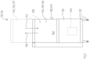
- FIG 1 An embodiment of a cleaning device 110 according to the invention is shown.
- the cleaning device 110 is designed in this embodiment as a pass-through dishwasher 112, which comprises an infeed table or feed table 114, a hood-type dishwasher 116, and an outfeed table 118.
- the cleaning device 110 is in Figure 1 shown in front view.
- the hood dishwasher 116 is shown again in a side view.
- the cleaning device 110 can, for example, comprise a basin 120 and a hose spray 122 for pre-cleaning the items to be cleaned 124 in the area of the inlet table 114.
- the items to be cleaned 124 can, for example, be introduced into a cleaning chamber 128 of the cleaning device 110 by means of one or more dish baskets 126. There, the items to be cleaned 124 can be exposed to one or more cleaning fluids, for example via one or more Figures 1 and 2 not shown in detail, for example nozzle systems.
- the hood-type dishwasher 116 has a base 130, which has, for example, a frame 132. Furthermore, the hood-type dishwasher 116 comprises a covering device 134, which is designed as a hood 136.
- This hood 136 can be opened via an opening path and is in the Figures 1 and 2 each shown with solid lines in a closed position 135 and with dashed lines in an open position 137.
- the direction of movement from the closed position 135 to the open position 137 defines an opening movement direction 139
- the opposite direction of movement from the open position 137 to the closed position 135 defines a closing movement direction 141.
- the hood-type dishwasher 116 further comprises at least one actuating element 138 in the form of a handle 140.
- the handle 140 is shown with solid lines in the closed position 135, and with dashed lines in the open position 137.
- the handle 140 for example, engages directly on the hood 136.
- At least one controller 148 can also be arranged in the base 130 of the hood-type dishwasher 116. However, a controller 148 can also be arranged alternatively or additionally at other locations of the hood-type dishwasher 116. Furthermore, further elements can be arranged in the base 130, such as at least one treatment tank in which a rinse liquid can be tempered. for example, at least one boiler. These elements are not shown in the figures.
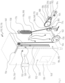
- the hood 136 is connected to at least one electromechanical drive 188 via at least one gear 184.
- the electromechanical drive 188 is configured to move the hood 136 in the opening movement direction 139 or the closing movement direction 141 via the gear 184, for example, to move the hood 136 from the closed position 135 to the open position 137 or vice versa.
- the gear 184 can, for example, be or have a traction mechanism 185, as described below, as explained in more detail below.
- the gear 184 comprises, for example, a power transmission path 182, one or more torque transmission elements 168, one or more torque converters 166, one or more sprockets 162, 170, one or more traction mechanisms 158, 172, and optionally further elements.
- other types of transmissions 184 can also be used within the scope of the present invention, for example, transmissions 184 without traction means and/or transmissions 184 without torque converters. The following description of transmission 184 should therefore be considered exemplary.
- the cleaning device 110 has guide elements 150 on both sides of its rear side, one of these guide elements 150 in Figure 3
- This guide element 150 can, as shown in Figure 3 shown, for example, a guide rail 152 or another type of guide profile, for example a rectangular profile in the form of a rectangular tube and/or square tube. This is, as shown in Figure 3 shown, arranged vertically.
- Each guide element 150 is supported, for example, by rollers 154, for example, three rollers on each side.
- a cantilever arm 156 is formed at the top of each guide element 150, onto which the hood 136, for example a completely pre-assembled one, can be pushed and secured, for example, with only a few fastening elements, e.g., two screws.
- a first traction means 158 for example, at least one first roller chain, is attached to the bottom of each guide element 150.
- This first traction means 158 is guided via a deflection wheel 160 in the upper region of a housing of the cleaning device 110.
- the first traction means 158 is further placed on a first sprocket 162 in the lower region of the housing.
- the illustrated arrangement of the guide element 150, the first traction means 158, the deflection wheel 160, and the first sprocket 162 is duplicated on the opposite side of the rear of the cleaning device 110, so that two, for example, identical, first sprockets 162 exist, of which Figure 3 To simplify the illustration, only one is shown.
- the two first sprockets 162 are connected to one another in a torsionally rigid manner via a shaft 164, to which they are mounted in a rotationally rigid manner.
- a torque converter 166 is mounted on this shaft 164, also in a torsionally rigid manner.
- This torque converter comprises a rotatably mounted torque transmission element 168, which in this exemplary embodiment is designed as a third sprocket 170.
- This third sprocket 170 is rotatably mounted about the axis of the shaft 164.
- the torque transmission element 168 in the form of the third chain wheel 170 is designed, for example, with an uneven radius, as in Figure 3 This means that a distance R between the point of application 174 and the axis changes with an angular position of the torque transmission element 168. However, this also changes the torque transmitted by the third traction means 172 to the shaft 164, since this torque depends on the angular position of the sprocket 170.
- the two chains of the first traction means 158 which are attached to the bottom of the guide rails 152, are largely unwound from the sprockets 162.
- the third traction means 172 also designed in the form of a roller chain, for example, is largely wound on its third sprocket 170, and the spring elements 176, which are designed as tension springs, for example, are, as in Figure 3 shown, tensioned.
- the hood 136 is raised, the first two traction means 158 wind up onto their wheels 162.
- the third traction means 172 is unwound, and the spring elements 176 relax.
- the third sprocket 170 has an effective radius and/or pitch circle that changes over its circumference.
- This design allows the change in the spring force over the opening travel or over the extension to the force actually required to compensate for the weight of the hood 136.
- non-uniform adjustments of the effective radius R can also be realized. For example, to dampen a movement at the end positions, sudden diameter changes can also be incorporated into the sprockets.
- the traction means 158 and the torque converter 166 are components of a power transmission line 182, by means of which a spring force of the at least one spring element 176 can be transmitted to the cover device 134 in a converted form.
- the power transmission line 182 is a component of the transmission 184. Further components of the power transmission line can be the deflection wheels 160 as well as the first chain wheels 162 and the shaft 164. Due to the effective radius R, which varies across the angular position, the torque converter 166 and thus the entire power transmission line 182 has a transmission ratio that varies across the opening travel.
- the torque converter 166 is thus, for example, a component of the transmission 184, which in this exemplary embodiment has a variable transmission ratio that varies across the opening travel of the cover 136.
- a component of the transmission 184 which in this exemplary embodiment has a variable transmission ratio that varies across the opening travel of the cover 136.
- embodiments of the present invention are also possible in which no transmission 184 with a variable gear ratio is used, but rather a transmission with a fixed gear ratio.
- the sprockets 162, 170 can, for example, be individually manufactured and assembled from metal. Furthermore, individual parts of the gear set, such as guide discs, can also be made entirely or partially from plastic. Manufacturing the entire gear set from plastic is also conceivable.
- the gear set is preferably mounted on roller bearings, which reduces friction and thus enables smooth running.
- the sprockets 162 and the shaft 164, as well as the traction means 158, 172, can be further components of the transmission 184.
- At least one electromechanical drive 186 is coupled to the gear 184, for example, at least one motor and particularly preferably at least one electric motor.
- this can be a DC gear motor.
- the electromechanical drive 186 can, for example, be driven by means of a further chain 188 and/or another type of traction means as well as by means of two pinions 190, which can be of the same or different types, and/or by means of another gearbox with a fixed or variable gear ratio.
- the electric motor can be mounted in such a way that its torque is absorbed by a spring-supported torque support 192. If the torque is too high, for example, if the closing force on the hood 136 is too high, this torque support 192 is deflected. This movement can be detected, for example, by a switch 194, which can transmit its signal to the controller 148. The controller 148 can then, for example, stop the movement of the hood 136 and optionally initiate a reverse movement.
- At least one rotary encoder can be integrated into the power transmission line 182, including the electromechanical drive 186, which can also be connected to the controller 148.
- This rotary encoder is in Figure 3 not shown.
- the controller 148 can, for example, detect when the signals from the rotary encoder are missing, for example because a movement is obstructed. In this case, the controller 148 can then, for example, stop the movement of the hood and/or initiate a reverse movement. To limit any crushing force that may occur, the weight compensation force for the hood 136 can be adjusted to the closing force of the drive so that safe values are not exceeded.
- the power transmission line 182 can be designed redundantly.
- a single third traction device 172 such as a single third chain
- two chains can be used in parallel or "back to back.”
- the third traction device 172 can be supplemented by another deformable component and/or traction device, such as a rope, which can absorb the tensile force in the event of a chain break.
- the spring element 176 can have at least one securing element 196 which, for example, can be a direct component of the spring elements 176 or, what is also intended to be included, can be coupled to them.
- this securing element 196 can comprise a catching element or a catching device, which in this exemplary embodiment are coupled to the two spring elements 176.
- this securing element can have at least one securing rod 198, wherein the force transmission path 182 can couple to the securing rod 198 in the event of a break in at least one spring element 176 or, in the case of multiple spring elements 176, to the force transmission path 182.
- the force transmission path 182 can couple to the securing rod 198 in the event of a break in at least one spring element 176 or, in the case of multiple spring elements 176, to the force transmission path 182.
- other configurations are also possible.
- two first traction means 158 can be provided.
- a different number is also possible.
- two or more of the aforementioned elements can also be combined in whole or in part.
- the two first traction means 158 can also be shorter and connected, for example, with a single chain, which can then be individually connected to the weight-compensating spring elements 176 via the gear set.
- roller chains can also be implemented with other flexible or deformable traction means, or in combination with various types of traction means.
- traction means for example, bolt chains, link chains, belts, or ropes can be used.
- a user can, for example, actuate one or more operating elements 200, which can be arranged, for example, laterally or on a front side of the base 130 and/or the hood 136. These can, for example, act on the controller 148, which in turn controls the electromechanical drive 186.
- the arrangement and electrical connection of the at least one operating element 200 are fundamentally problematic.
- the operating personnel may have to leave the workstation at the basin 120 in order to initiate movement of the hood 136.
- At least one sensor 202 is provided within the scope of the present invention, which is configured to detect a manual force application to the covering device 134 and preferably also the direction of this force application.
- the hood 136 can be opened by a user when it is in the closed Position 135, can be slightly raised, i.e. moved in the opening movement direction 139, which is detected by the sensor 202.
- movements of 5 mm or more or movements greater than 5 mm can be detected as a desire to move the hood 136 in this direction.
- the hood 136 can be pulled slightly downwards in the closing movement direction 141 by a user when it is in the open position 137, which is detected by the sensor 202.
- the detection of this force application and, if applicable, the direction of this force application can then be converted by the controller 148 into a corresponding control command for the electromechanical drive 186 in order to subsequently support the movement of the hood 136 in the desired direction by the electromechanical drive 186 or even to carry it out exclusively by the electromechanical drive 186.
- the hood 136 itself can therefore be used as a type of control element 200 in that a request regarding a movement of the hood 136 is transmitted to the control 148 by means of a force application to this hood 136.
- the sensor 202 can generally be arranged at various locations within the cleaning device 110.
- the at least one sensor 202 can be arranged at one or more of the following locations: on the hood 136; on the guide element 150; on the guide rail 152; within the gear 184, for example, within the power transmission path 182 and/or at another location within the gear 184; in the electromechanical drive 186.
- the electromechanical drive 186 and/or the gear 184 can, for example, comprise at least one driven shaft 204, which is preferably rotatable by the electromechanical drive 186, preferably in both possible directions of rotation.
- the sensor 202 can, for example, comprise an incremental encoder 206, which can, for example, be arranged at a shaft end of the shaft 204.
- the sensor 202 can, for example, be connected wirelessly or by wire to the controller 148 in order to communicate with it unidirectionally or bidirectionally.
- the controller 148 can, for example, be configured to evaluate the information from the sensor 202 and issue corresponding control commands to the electromechanical drive 186.
- the electromechanical drive 186 can be connected directly or indirectly, for example wirelessly or by wire, to the controller 148.
- the controller 148 can be configured to start the electromechanical drive 186, influence its direction of rotation, or even its rotational speed. Other configurations are also possible.
- the controller 148 can, for example, be configured to programmatically evaluate signals and/or information from sensor 202, for example by using a threshold value method.
- a change in the position and/or an increment transmitted by sensor 202 can be monitored and compared, for example, with one or more threshold values.
- the monitoring described above can be carried out to determine whether the hood 136 has been moved by more than a predetermined distance due to the manual application of force, which can then be interpreted as a command for further movement in the direction of this application of force.
- the electromechanical drive 186 can be configured, in particular, as a DC geared motor.
- the DC geared motor can, for example, be designed so that it is not self-locking. This allows manual movement and/or the hood 136 can also be operated manually in the event of a malfunction.
- the motor can be moved along with it.
- the incremental encoder 206 can, for example, detect a rotary movement of the motor and the associated operating direction, and transmit these signals to the controller 148.
- the controller 148 can, for example, evaluate this signal, interpret the movement request, and then drive the motor in the appropriate direction.
- the cleaning device 110 can also have additional functions.
- it can be configured to carry out at least one cleaning program, for example, by means of a corresponding programming device of the controller 148. For example, after a closing movement, when the hood 136 is in the closed position 135, a rinsing program can be started automatically.
- the handle 140 is usually located in an ergonomically favorable position on the hood 136, for example in an ergonomically favorable position relative to a workstation at the basin 120. Operating personnel at this workstation can thus easily reach the handle 140 and thereby initiate the hood movement, even without visual contact with the controller 148 and/or corresponding operating elements 200.
- a teaching This is generally not necessary, since the hood movement is initiated intuitively with a corresponding movement of the handle 140. This results in a user-friendly and safe overall situation of the cleaning device 110.
Landscapes
- Washing And Drying Of Tableware (AREA)
- Cleaning By Liquid Or Steam (AREA)
Priority Applications (3)
| Application Number | Priority Date | Filing Date | Title |
|---|---|---|---|
| PL17714452.4T PL3324811T5 (pl) | 2016-03-31 | 2017-03-30 | Urządzenie oczyszczające i sposób oczyszczania artykułów do oczyszczania |
| PL20173746T PL3753468T3 (pl) | 2016-03-31 | 2017-03-30 | Urządzenie oczyszczające i sposób oczyszczania artykułów do oczyszczania |
| EP20173746.7A EP3753468B1 (de) | 2016-03-31 | 2017-03-30 | Reinigungsvorrichtung und verfahren zum reinigen von reinigungsgut |
Applications Claiming Priority (2)
| Application Number | Priority Date | Filing Date | Title |
|---|---|---|---|
| DE102016205367.1A DE102016205367A1 (de) | 2016-03-31 | 2016-03-31 | Reinigungsvorrichtung und Verfahren zum Reinigen von Reinigungsgut |
| PCT/EP2017/057540 WO2017167874A1 (de) | 2016-03-31 | 2017-03-30 | Reinigungsvorrichtung und verfahren zum reinigen von reinigungsgut |
Related Child Applications (2)
| Application Number | Title | Priority Date | Filing Date |
|---|---|---|---|
| EP20173746.7A Division EP3753468B1 (de) | 2016-03-31 | 2017-03-30 | Reinigungsvorrichtung und verfahren zum reinigen von reinigungsgut |
| EP20173746.7A Division-Into EP3753468B1 (de) | 2016-03-31 | 2017-03-30 | Reinigungsvorrichtung und verfahren zum reinigen von reinigungsgut |
Publications (3)
| Publication Number | Publication Date |
|---|---|
| EP3324811A1 EP3324811A1 (de) | 2018-05-30 |
| EP3324811B1 EP3324811B1 (de) | 2020-05-27 |
| EP3324811B2 true EP3324811B2 (de) | 2025-06-25 |
Family
ID=58455056
Family Applications (2)
| Application Number | Title | Priority Date | Filing Date |
|---|---|---|---|
| EP20173746.7A Active EP3753468B1 (de) | 2016-03-31 | 2017-03-30 | Reinigungsvorrichtung und verfahren zum reinigen von reinigungsgut |
| EP17714452.4A Active EP3324811B2 (de) | 2016-03-31 | 2017-03-30 | Reinigungsvorrichtung und verfahren zum reinigen von reinigungsgut |
Family Applications Before (1)
| Application Number | Title | Priority Date | Filing Date |
|---|---|---|---|
| EP20173746.7A Active EP3753468B1 (de) | 2016-03-31 | 2017-03-30 | Reinigungsvorrichtung und verfahren zum reinigen von reinigungsgut |
Country Status (7)
| Country | Link |
|---|---|
| US (2) | US10617277B2 (pl) |
| EP (2) | EP3753468B1 (pl) |
| CN (1) | CN107635449B (pl) |
| DE (1) | DE102016205367A1 (pl) |
| ES (2) | ES2812832T5 (pl) |
| PL (2) | PL3324811T5 (pl) |
| WO (1) | WO2017167874A1 (pl) |
Families Citing this family (12)
| Publication number | Priority date | Publication date | Assignee | Title |
|---|---|---|---|---|
| DE102016205367A1 (de) | 2016-03-31 | 2017-10-05 | Meiko Maschinenbau Gmbh & Co. Kg | Reinigungsvorrichtung und Verfahren zum Reinigen von Reinigungsgut |
| USD884996S1 (en) * | 2017-03-09 | 2020-05-19 | Meiko Maschinenbau Gmbh & Co. Kg | Rinsing machine |
| DE102018217052A1 (de) * | 2018-10-05 | 2020-04-09 | Meiko Maschinenbau Gmbh & Co. Kg | Reinigungsvorrichtung und Verfahren zur Reinigung von Reinigungsgut |
| DE102019202139A1 (de) * | 2019-02-18 | 2020-08-20 | Meiko Maschinenbau Gmbh & Co. Kg | Spülkorb zur Reinigung von Hohlräumen in Reinigungsgut |
| CN110123235B (zh) * | 2019-05-21 | 2024-11-12 | 广东万和电气有限公司 | 嵌入式洗碗机及其开关门机构 |
| DE102019114740A1 (de) * | 2019-06-03 | 2020-12-03 | Miele & Cie. Kg | Wasserführendes Haushaltsgerät und Verfahren zum Betreiben des wasserführenden Haushaltsgeräts |
| DE102019210272A1 (de) * | 2019-07-11 | 2021-01-14 | Meiko Maschinenbau Gmbh & Co. Kg | Reinigungsvorrichtung mit Korbrückführung |
| DE102020104523A1 (de) | 2020-02-20 | 2021-08-26 | Illinois Tool Works Inc. | Spülmaschine |
| DE102020207064A1 (de) * | 2020-06-05 | 2021-12-09 | BSH Hausgeräte GmbH | Richtungsabhängige Aktivierung der Türbetätigung einer Haushaltsgeschirrspülmaschine |
| KR102360813B1 (ko) * | 2021-06-18 | 2022-02-09 | 김현태 | 진공 청소기의 먼지떨이 장치 |
| DE102021125824A1 (de) * | 2021-10-05 | 2023-04-06 | Ampack Gmbh | Abdeckvorrichtung für eine Abfüllstation und Abfüllstation mit einer solchen Abdeckvorrichtung |
| EP4537730B1 (en) * | 2023-10-12 | 2026-02-04 | Illinois Tool Works Inc. | Dishwasher |
Citations (14)
| Publication number | Priority date | Publication date | Assignee | Title |
|---|---|---|---|---|
| US3589787A (en) † | 1969-11-12 | 1971-06-29 | Alco Standard Corp | Dishwasher door operator |
| US4073555A (en) † | 1975-12-22 | 1978-02-14 | Noren Tore H | Dishwasher with downwardly movable door counterbalanced by spring-biased toggle joints |
| EP0541974A1 (de) † | 1991-11-12 | 1993-05-19 | Miele & Cie. GmbH & Co. | Haushaltgerät, insbesondere Geschirrspülmaschine oder Herd mit einem durch eine Gerätetür verschliessbaren Spül- oder Backraum |
| DE19514303A1 (de) † | 1995-04-25 | 1996-10-31 | Miele & Cie | Spülautomat insbesondere für den Labor- und Krankenhausbereich, mit einem durch eine Hubtür verschließbaren Spülraum |
| DE10054392A1 (de) † | 2000-11-02 | 2002-05-08 | Winterhalter Gastronom Gmbh | Antriebsvorrichtung |
| DE102006061083A1 (de) † | 2006-12-22 | 2008-06-26 | BSH Bosch und Siemens Hausgeräte GmbH | Kältegerät mit Türöffnungshilfe |
| DE102008021496A1 (de) † | 2008-04-29 | 2009-11-05 | Miele & Cie. Kg | Haushaltsgerät |
| DE102008028313A1 (de) † | 2008-06-13 | 2009-12-17 | BSH Bosch und Siemens Hausgeräte GmbH | Kapazitiver Berührungsschalter für ein Haushaltsgerät |
| DE102010037397A1 (de) † | 2010-09-08 | 2012-03-08 | Miele & Cie. Kg | Haushaltgerät, insbesondere grifflose Geschirrspülmaschine |
| DE102011004019A1 (de) † | 2011-02-14 | 2012-08-16 | Siemens Aktiengesellschaft | Elektrisch angetriebene Tür |
| DE102012223219A1 (de) † | 2012-12-14 | 2014-06-18 | BSH Bosch und Siemens Hausgeräte GmbH | Haushaltsgerät |
| DE102013224148A1 (de) † | 2013-11-26 | 2015-05-28 | Siemens Aktiengesellschaft | Verfahren zur Steuerung eines elektrischen Antriebs einer Tür oder eines Türflügels sowie Türsteuereinrichtung |
| DE102014111718B3 (de) † | 2014-08-18 | 2015-12-03 | Miele & Cie. Kg | Spülautomat, insbesondere Desinfektionsautomat oder Endoskopspüler |
| DE102014107544A1 (de) † | 2014-05-28 | 2015-12-03 | Miele & Cie. Kg | Backofen |
Family Cites Families (24)
| Publication number | Priority date | Publication date | Assignee | Title |
|---|---|---|---|---|
| DE3144280A1 (de) | 1981-11-07 | 1983-05-19 | Robert Bosch Gmbh, 7000 Stuttgart | Elektro-mechanischer stellantrieb |
| CN2164255Y (zh) * | 1993-05-25 | 1994-05-11 | 杨水川 | 热循环式洗碗机 |
| EP1125885B1 (de) | 2000-01-18 | 2006-03-01 | Helmut Meyerdierks | Winsch |
| US6719356B2 (en) | 2001-04-26 | 2004-04-13 | Litens Automotive | Powered opening mechanism and control system |
| WO2003062575A1 (en) | 2002-01-24 | 2003-07-31 | Intier Automotive Closures Inc. | Power lift gate actuator |
| JP2005124800A (ja) * | 2003-10-23 | 2005-05-19 | Toshiba Corp | 電気機器の電動扉及び食器洗浄機 |
| CA2514670A1 (en) | 2004-08-06 | 2006-02-06 | Magna Closures Inc. | Electromechanical strut |
| DE102005030052B4 (de) | 2005-06-27 | 2012-03-08 | Stabilus Gmbh | Antriebseinrichtung |
| AU2007260348B2 (en) | 2006-06-13 | 2011-06-02 | Linak A/S | Actuator |
| DE102007003451B4 (de) | 2007-01-17 | 2009-01-08 | Stiefel Gmbh | Schrank mit einem oder mehreren Auszügen |
| DE202007006818U1 (de) | 2007-01-17 | 2007-10-18 | Stiefel Gmbh | Schrank mit einem oder mehreren Auszügen |
| DE102008009898B4 (de) | 2007-11-13 | 2010-07-15 | Stabilus Gmbh | Klappenöffnungs- und -schließsystem |
| DE102011002950A1 (de) | 2011-01-21 | 2012-07-26 | BSH Bosch und Siemens Hausgeräte GmbH | Vorrichtung mit einem beweglichen Vorrichtungsteil |
| DE102011001168A1 (de) | 2011-03-09 | 2012-09-13 | Miele & Cie. Kg | Verfahren zum Betrieb eines Haushaltgeräts |
| DE102011079534A1 (de) * | 2011-07-21 | 2013-01-24 | BSH Bosch und Siemens Hausgeräte GmbH | Geschirrspülmaschine und Verfahren zum Öffnen einer Tür einer Geschirrspülmaschine |
| JP2013027630A (ja) * | 2011-07-29 | 2013-02-07 | Hoshizaki Electric Co Ltd | 食器洗浄機 |
| JP6008756B2 (ja) | 2012-02-24 | 2016-10-19 | 三菱電機株式会社 | 電流センサおよび三相交流用電流センサ装置 |
| DE102012223775A1 (de) | 2012-12-19 | 2014-06-26 | BSH Bosch und Siemens Hausgeräte GmbH | Haushaltsgerät mit einem Körperschallsensor, System und entsprechendes Verfahren |
| CN103006156B (zh) * | 2012-12-28 | 2015-04-15 | 苏州韩博厨房电器科技有限公司 | 一种自动洗碗机 |
| DE102014007172A1 (de) | 2014-05-15 | 2015-11-19 | Diehl Ako Stiftung & Co. Kg | Vorrichtung zur Bedienung eines elektronischen Geräts |
| FR3023162A1 (fr) | 2014-07-02 | 2016-01-08 | Ac & Co Technologies | Appareil de massage comprenant un empilement de cellules gonflables/degonflables inclinees et en chevauchement les unes par rapport aux autres |
| DE102015205602A1 (de) * | 2015-03-27 | 2016-09-29 | Meiko Maschinenbau Gmbh & Co. Kg | Reinigungsvorrichtung und Verfahren zum Reinigen von Reinigungsgut |
| CN105167727A (zh) * | 2015-08-14 | 2015-12-23 | 浙江法斯特电梯有限公司 | 一种自动循环洗碗机 |
| DE102016205367A1 (de) | 2016-03-31 | 2017-10-05 | Meiko Maschinenbau Gmbh & Co. Kg | Reinigungsvorrichtung und Verfahren zum Reinigen von Reinigungsgut |
-
2016
- 2016-03-31 DE DE102016205367.1A patent/DE102016205367A1/de active Pending
-
2017
- 2017-03-30 WO PCT/EP2017/057540 patent/WO2017167874A1/de not_active Ceased
- 2017-03-30 PL PL17714452.4T patent/PL3324811T5/pl unknown
- 2017-03-30 ES ES17714452T patent/ES2812832T5/es active Active
- 2017-03-30 CN CN201780001589.9A patent/CN107635449B/zh active Active
- 2017-03-30 ES ES20173746T patent/ES2909786T3/es active Active
- 2017-03-30 EP EP20173746.7A patent/EP3753468B1/de active Active
- 2017-03-30 PL PL20173746T patent/PL3753468T3/pl unknown
- 2017-03-30 EP EP17714452.4A patent/EP3324811B2/de active Active
- 2017-10-30 US US15/797,785 patent/US10617277B2/en active Active
-
2020
- 2020-03-03 US US16/808,027 patent/US11253132B2/en active Active
Patent Citations (14)
| Publication number | Priority date | Publication date | Assignee | Title |
|---|---|---|---|---|
| US3589787A (en) † | 1969-11-12 | 1971-06-29 | Alco Standard Corp | Dishwasher door operator |
| US4073555A (en) † | 1975-12-22 | 1978-02-14 | Noren Tore H | Dishwasher with downwardly movable door counterbalanced by spring-biased toggle joints |
| EP0541974A1 (de) † | 1991-11-12 | 1993-05-19 | Miele & Cie. GmbH & Co. | Haushaltgerät, insbesondere Geschirrspülmaschine oder Herd mit einem durch eine Gerätetür verschliessbaren Spül- oder Backraum |
| DE19514303A1 (de) † | 1995-04-25 | 1996-10-31 | Miele & Cie | Spülautomat insbesondere für den Labor- und Krankenhausbereich, mit einem durch eine Hubtür verschließbaren Spülraum |
| DE10054392A1 (de) † | 2000-11-02 | 2002-05-08 | Winterhalter Gastronom Gmbh | Antriebsvorrichtung |
| DE102006061083A1 (de) † | 2006-12-22 | 2008-06-26 | BSH Bosch und Siemens Hausgeräte GmbH | Kältegerät mit Türöffnungshilfe |
| DE102008021496A1 (de) † | 2008-04-29 | 2009-11-05 | Miele & Cie. Kg | Haushaltsgerät |
| DE102008028313A1 (de) † | 2008-06-13 | 2009-12-17 | BSH Bosch und Siemens Hausgeräte GmbH | Kapazitiver Berührungsschalter für ein Haushaltsgerät |
| DE102010037397A1 (de) † | 2010-09-08 | 2012-03-08 | Miele & Cie. Kg | Haushaltgerät, insbesondere grifflose Geschirrspülmaschine |
| DE102011004019A1 (de) † | 2011-02-14 | 2012-08-16 | Siemens Aktiengesellschaft | Elektrisch angetriebene Tür |
| DE102012223219A1 (de) † | 2012-12-14 | 2014-06-18 | BSH Bosch und Siemens Hausgeräte GmbH | Haushaltsgerät |
| DE102013224148A1 (de) † | 2013-11-26 | 2015-05-28 | Siemens Aktiengesellschaft | Verfahren zur Steuerung eines elektrischen Antriebs einer Tür oder eines Türflügels sowie Türsteuereinrichtung |
| DE102014107544A1 (de) † | 2014-05-28 | 2015-12-03 | Miele & Cie. Kg | Backofen |
| DE102014111718B3 (de) † | 2014-08-18 | 2015-12-03 | Miele & Cie. Kg | Spülautomat, insbesondere Desinfektionsautomat oder Endoskopspüler |
Non-Patent Citations (4)
| Title |
|---|
| Betriebsanleitung zur Haubenspülmaschine AMX/AUX † |
| Comic-Cards zum Thema "Haubenlift" † |
| Ergänzende Installations- und Betriebsanleitung zum Thema„Haubenlift" † |
| Preisliste vom 01.10.2008 † |
Also Published As
| Publication number | Publication date |
|---|---|
| ES2812832T3 (es) | 2021-03-18 |
| US20180055329A1 (en) | 2018-03-01 |
| HK1245045A1 (zh) | 2018-08-24 |
| PL3753468T3 (pl) | 2022-05-23 |
| CN107635449A (zh) | 2018-01-26 |
| EP3753468A1 (de) | 2020-12-23 |
| WO2017167874A1 (de) | 2017-10-05 |
| ES2909786T3 (es) | 2022-05-10 |
| US20200196828A1 (en) | 2020-06-25 |
| ES2812832T5 (en) | 2025-08-20 |
| DE102016205367A1 (de) | 2017-10-05 |
| PL3324811T3 (pl) | 2020-11-16 |
| US11253132B2 (en) | 2022-02-22 |
| EP3324811A1 (de) | 2018-05-30 |
| US10617277B2 (en) | 2020-04-14 |
| PL3324811T5 (pl) | 2025-11-03 |
| EP3753468B1 (de) | 2022-01-19 |
| CN107635449B (zh) | 2021-10-01 |
| EP3324811B1 (de) | 2020-05-27 |
Similar Documents
| Publication | Publication Date | Title |
|---|---|---|
| EP3324811B2 (de) | Reinigungsvorrichtung und verfahren zum reinigen von reinigungsgut | |
| EP2280631B1 (de) | Geschirrspülmaschine | |
| EP3697281B1 (de) | Haushaltsgerät | |
| EP4026474B1 (de) | Geschirrspülmaschine | |
| WO2011039362A1 (de) | Türvorrichtung für ein hausgerät, hausgerät mit einer derartigen türvorrichtung sowie verfahren zum betätigen einer türvorrichtung für ein hausgerät | |
| EP3085294A1 (de) | Hebevorrichtung und geschirrspülmaschine | |
| EP3393329B1 (de) | Geschirrspülmaschine mit einer hebevorrichtung und verfahren zum betreiben einer hebevorrichtung | |
| DE102005010616A1 (de) | Geschirrspülmaschine mit einem Lagerungsbehälter | |
| EP3463031B1 (de) | Haushaltsgeschirrspülmaschine | |
| DE102012207836A1 (de) | Haushaltsgerät | |
| DE102017213699B4 (de) | Haushaltsgeschirrspülmaschine | |
| EP3273836B1 (de) | Reinigungsvorrichtung und verfahren zum reinigen von reinigungsgut | |
| EP4161338B1 (de) | Richtungsabhängige aktivierung der türbetätigung einer haushaltsgeschirrspülmaschine | |
| EP2734100B1 (de) | Geschirrspülmaschine und verfahren zum öffnen einer tür einer geschirrspülmaschine | |
| DE102007007954B3 (de) | Eckschrank, insbesondere Kücheneckschrank | |
| EP4370005B1 (de) | Haushaltsgeschirrspülmaschine | |
| DE102008047556B3 (de) | Vorrichtung mit einem Griff | |
| DE102016201727B4 (de) | Hebevorrichtung, Verfahren zum Betreiben einer Hebevorrichtung und Geschirrspülmaschine | |
| DE102020100015A1 (de) | Geschirrspülmaschine, insbesondere Haushaltsgeschirrspülmaschine | |
| EP4491088B1 (de) | Geschirrspülmaschine | |
| DE102016222351B4 (de) | Hebevorrichtung und Geschirrspülmaschine | |
| EP2851499A1 (de) | Verfahren zum Betrieb wenigstens eines elektromotorisch angetriebenen Türflügels |
Legal Events
| Date | Code | Title | Description |
|---|---|---|---|
| STAA | Information on the status of an ep patent application or granted ep patent |
Free format text: STATUS: UNKNOWN |
|
| STAA | Information on the status of an ep patent application or granted ep patent |
Free format text: STATUS: THE INTERNATIONAL PUBLICATION HAS BEEN MADE |
|
| PUAI | Public reference made under article 153(3) epc to a published international application that has entered the european phase |
Free format text: ORIGINAL CODE: 0009012 |
|
| STAA | Information on the status of an ep patent application or granted ep patent |
Free format text: STATUS: REQUEST FOR EXAMINATION WAS MADE |
|
| 17P | Request for examination filed |
Effective date: 20180226 |
|
| AK | Designated contracting states |
Kind code of ref document: A1 Designated state(s): AL AT BE BG CH CY CZ DE DK EE ES FI FR GB GR HR HU IE IS IT LI LT LU LV MC MK MT NL NO PL PT RO RS SE SI SK SM TR |
|
| AX | Request for extension of the european patent |
Extension state: BA ME |
|
| DAV | Request for validation of the european patent (deleted) | ||
| DAX | Request for extension of the european patent (deleted) | ||
| GRAP | Despatch of communication of intention to grant a patent |
Free format text: ORIGINAL CODE: EPIDOSNIGR1 |
|
| STAA | Information on the status of an ep patent application or granted ep patent |
Free format text: STATUS: GRANT OF PATENT IS INTENDED |
|
| INTG | Intention to grant announced |
Effective date: 20191111 |
|
| INTG | Intention to grant announced |
Effective date: 20191111 |
|
| INTG | Intention to grant announced |
Effective date: 20191118 |
|
| GRAS | Grant fee paid |
Free format text: ORIGINAL CODE: EPIDOSNIGR3 |
|
| TPAC | Observations filed by third parties |
Free format text: ORIGINAL CODE: EPIDOSNTIPA |
|
| GRAA | (expected) grant |
Free format text: ORIGINAL CODE: 0009210 |
|
| STAA | Information on the status of an ep patent application or granted ep patent |
Free format text: STATUS: THE PATENT HAS BEEN GRANTED |
|
| AK | Designated contracting states |
Kind code of ref document: B1 Designated state(s): AL AT BE BG CH CY CZ DE DK EE ES FI FR GB GR HR HU IE IS IT LI LT LU LV MC MK MT NL NO PL PT RO RS SE SI SK SM TR |
|
| REG | Reference to a national code |
Ref country code: GB Ref legal event code: FG4D Free format text: NOT ENGLISH |
|
| REG | Reference to a national code |
Ref country code: CH Ref legal event code: EP |
|
| REG | Reference to a national code |
Ref country code: DE Ref legal event code: R096 Ref document number: 502017005446 Country of ref document: DE |
|
| REG | Reference to a national code |
Ref country code: AT Ref legal event code: REF Ref document number: 1273641 Country of ref document: AT Kind code of ref document: T Effective date: 20200615 |
|
| REG | Reference to a national code |
Ref country code: CH Ref legal event code: NV Representative=s name: SCHMAUDER AND PARTNER AG PATENT- UND MARKENANW, CH |
|
| REG | Reference to a national code |
Ref country code: NL Ref legal event code: FP |
|
| REG | Reference to a national code |
Ref country code: SE Ref legal event code: TRGR |
|
| REG | Reference to a national code |
Ref country code: LT Ref legal event code: MG4D |
|
| PG25 | Lapsed in a contracting state [announced via postgrant information from national office to epo] |
Ref country code: PT Free format text: LAPSE BECAUSE OF FAILURE TO SUBMIT A TRANSLATION OF THE DESCRIPTION OR TO PAY THE FEE WITHIN THE PRESCRIBED TIME-LIMIT Effective date: 20200928 Ref country code: IS Free format text: LAPSE BECAUSE OF FAILURE TO SUBMIT A TRANSLATION OF THE DESCRIPTION OR TO PAY THE FEE WITHIN THE PRESCRIBED TIME-LIMIT Effective date: 20200927 Ref country code: FI Free format text: LAPSE BECAUSE OF FAILURE TO SUBMIT A TRANSLATION OF THE DESCRIPTION OR TO PAY THE FEE WITHIN THE PRESCRIBED TIME-LIMIT Effective date: 20200527 Ref country code: LT Free format text: LAPSE BECAUSE OF FAILURE TO SUBMIT A TRANSLATION OF THE DESCRIPTION OR TO PAY THE FEE WITHIN THE PRESCRIBED TIME-LIMIT Effective date: 20200527 Ref country code: NO Free format text: LAPSE BECAUSE OF FAILURE TO SUBMIT A TRANSLATION OF THE DESCRIPTION OR TO PAY THE FEE WITHIN THE PRESCRIBED TIME-LIMIT Effective date: 20200827 Ref country code: GR Free format text: LAPSE BECAUSE OF FAILURE TO SUBMIT A TRANSLATION OF THE DESCRIPTION OR TO PAY THE FEE WITHIN THE PRESCRIBED TIME-LIMIT Effective date: 20200828 |
|
| PG25 | Lapsed in a contracting state [announced via postgrant information from national office to epo] |
Ref country code: BG Free format text: LAPSE BECAUSE OF FAILURE TO SUBMIT A TRANSLATION OF THE DESCRIPTION OR TO PAY THE FEE WITHIN THE PRESCRIBED TIME-LIMIT Effective date: 20200827 Ref country code: RS Free format text: LAPSE BECAUSE OF FAILURE TO SUBMIT A TRANSLATION OF THE DESCRIPTION OR TO PAY THE FEE WITHIN THE PRESCRIBED TIME-LIMIT Effective date: 20200527 Ref country code: HR Free format text: LAPSE BECAUSE OF FAILURE TO SUBMIT A TRANSLATION OF THE DESCRIPTION OR TO PAY THE FEE WITHIN THE PRESCRIBED TIME-LIMIT Effective date: 20200527 Ref country code: LV Free format text: LAPSE BECAUSE OF FAILURE TO SUBMIT A TRANSLATION OF THE DESCRIPTION OR TO PAY THE FEE WITHIN THE PRESCRIBED TIME-LIMIT Effective date: 20200527 |
|
| PG25 | Lapsed in a contracting state [announced via postgrant information from national office to epo] |
Ref country code: AL Free format text: LAPSE BECAUSE OF FAILURE TO SUBMIT A TRANSLATION OF THE DESCRIPTION OR TO PAY THE FEE WITHIN THE PRESCRIBED TIME-LIMIT Effective date: 20200527 |
|
| PG25 | Lapsed in a contracting state [announced via postgrant information from national office to epo] |
Ref country code: DK Free format text: LAPSE BECAUSE OF FAILURE TO SUBMIT A TRANSLATION OF THE DESCRIPTION OR TO PAY THE FEE WITHIN THE PRESCRIBED TIME-LIMIT Effective date: 20200527 Ref country code: SM Free format text: LAPSE BECAUSE OF FAILURE TO SUBMIT A TRANSLATION OF THE DESCRIPTION OR TO PAY THE FEE WITHIN THE PRESCRIBED TIME-LIMIT Effective date: 20200527 Ref country code: EE Free format text: LAPSE BECAUSE OF FAILURE TO SUBMIT A TRANSLATION OF THE DESCRIPTION OR TO PAY THE FEE WITHIN THE PRESCRIBED TIME-LIMIT Effective date: 20200527 Ref country code: CZ Free format text: LAPSE BECAUSE OF FAILURE TO SUBMIT A TRANSLATION OF THE DESCRIPTION OR TO PAY THE FEE WITHIN THE PRESCRIBED TIME-LIMIT Effective date: 20200527 Ref country code: RO Free format text: LAPSE BECAUSE OF FAILURE TO SUBMIT A TRANSLATION OF THE DESCRIPTION OR TO PAY THE FEE WITHIN THE PRESCRIBED TIME-LIMIT Effective date: 20200527 |
|
| REG | Reference to a national code |
Ref country code: DE Ref legal event code: R026 Ref document number: 502017005446 Country of ref document: DE |
|
| PG25 | Lapsed in a contracting state [announced via postgrant information from national office to epo] |
Ref country code: SK Free format text: LAPSE BECAUSE OF FAILURE TO SUBMIT A TRANSLATION OF THE DESCRIPTION OR TO PAY THE FEE WITHIN THE PRESCRIBED TIME-LIMIT Effective date: 20200527 |
|
| PLBI | Opposition filed |
Free format text: ORIGINAL CODE: 0009260 |
|
| PLBI | Opposition filed |
Free format text: ORIGINAL CODE: 0009260 |
|
| PLAX | Notice of opposition and request to file observation + time limit sent |
Free format text: ORIGINAL CODE: EPIDOSNOBS2 |
|
| REG | Reference to a national code |
Ref country code: ES Ref legal event code: FG2A Ref document number: 2812832 Country of ref document: ES Kind code of ref document: T3 Effective date: 20210318 |
|
| 26 | Opposition filed |
Opponent name: HOBART GMBH Effective date: 20210219 |
|
| 26 | Opposition filed |
Opponent name: WINTERHALTER GASTRONOM GMBH Effective date: 20210226 |
|
| PG25 | Lapsed in a contracting state [announced via postgrant information from national office to epo] |
Ref country code: SI Free format text: LAPSE BECAUSE OF FAILURE TO SUBMIT A TRANSLATION OF THE DESCRIPTION OR TO PAY THE FEE WITHIN THE PRESCRIBED TIME-LIMIT Effective date: 20200527 |
|
| PLAF | Information modified related to communication of a notice of opposition and request to file observations + time limit |
Free format text: ORIGINAL CODE: EPIDOSCOBS2 |
|
| PLBB | Reply of patent proprietor to notice(s) of opposition received |
Free format text: ORIGINAL CODE: EPIDOSNOBS3 |
|
| PG25 | Lapsed in a contracting state [announced via postgrant information from national office to epo] |
Ref country code: MC Free format text: LAPSE BECAUSE OF FAILURE TO SUBMIT A TRANSLATION OF THE DESCRIPTION OR TO PAY THE FEE WITHIN THE PRESCRIBED TIME-LIMIT Effective date: 20200527 |
|
| REG | Reference to a national code |
Ref country code: BE Ref legal event code: MM Effective date: 20210331 |
|
| PG25 | Lapsed in a contracting state [announced via postgrant information from national office to epo] |
Ref country code: IE Free format text: LAPSE BECAUSE OF NON-PAYMENT OF DUE FEES Effective date: 20210330 Ref country code: LU Free format text: LAPSE BECAUSE OF NON-PAYMENT OF DUE FEES Effective date: 20210330 |
|
| PG25 | Lapsed in a contracting state [announced via postgrant information from national office to epo] |
Ref country code: BE Free format text: LAPSE BECAUSE OF NON-PAYMENT OF DUE FEES Effective date: 20210331 |
|
| REG | Reference to a national code |
Ref country code: CH Ref legal event code: PK Free format text: BERICHTIGUNGEN |
|
| REG | Reference to a national code |
Ref country code: CH Ref legal event code: PK Free format text: BERICHTIGUNGEN |
|
| RIC2 | Information provided on ipc code assigned after grant |
Ipc: A47L 15/46 20060101ALN20221208BHEP Ipc: A47L 15/24 20060101ALN20221208BHEP Ipc: A47L 15/42 20060101ALI20221208BHEP Ipc: A47L 15/00 20060101AFI20221208BHEP |
|
| RIC2 | Information provided on ipc code assigned after grant |
Ipc: A47L 15/46 20060101ALN20221214BHEP Ipc: A47L 15/24 20060101ALN20221214BHEP Ipc: A47L 15/42 20060101ALI20221214BHEP Ipc: A47L 15/00 20060101AFI20221214BHEP |
|
| APAH | Appeal reference modified |
Free format text: ORIGINAL CODE: EPIDOSCREFNO |
|
| APBM | Appeal reference recorded |
Free format text: ORIGINAL CODE: EPIDOSNREFNO |
|
| APBP | Date of receipt of notice of appeal recorded |
Free format text: ORIGINAL CODE: EPIDOSNNOA2O |
|
| APBM | Appeal reference recorded |
Free format text: ORIGINAL CODE: EPIDOSNREFNO |
|
| APBP | Date of receipt of notice of appeal recorded |
Free format text: ORIGINAL CODE: EPIDOSNNOA2O |
|
| PLAB | Opposition data, opponent's data or that of the opponent's representative modified |
Free format text: ORIGINAL CODE: 0009299OPPO |
|
| R26 | Opposition filed (corrected) |
Opponent name: HOBART GMBH Effective date: 20210219 |
|
| APBQ | Date of receipt of statement of grounds of appeal recorded |
Free format text: ORIGINAL CODE: EPIDOSNNOA3O |
|
| P01 | Opt-out of the competence of the unified patent court (upc) registered |
Effective date: 20230508 |
|
| PG25 | Lapsed in a contracting state [announced via postgrant information from national office to epo] |
Ref country code: CY Free format text: LAPSE BECAUSE OF FAILURE TO SUBMIT A TRANSLATION OF THE DESCRIPTION OR TO PAY THE FEE WITHIN THE PRESCRIBED TIME-LIMIT Effective date: 20200527 |
|
| PG25 | Lapsed in a contracting state [announced via postgrant information from national office to epo] |
Ref country code: HU Free format text: LAPSE BECAUSE OF FAILURE TO SUBMIT A TRANSLATION OF THE DESCRIPTION OR TO PAY THE FEE WITHIN THE PRESCRIBED TIME-LIMIT; INVALID AB INITIO Effective date: 20170330 |
|
| PG25 | Lapsed in a contracting state [announced via postgrant information from national office to epo] |
Ref country code: MK Free format text: LAPSE BECAUSE OF FAILURE TO SUBMIT A TRANSLATION OF THE DESCRIPTION OR TO PAY THE FEE WITHIN THE PRESCRIBED TIME-LIMIT Effective date: 20200527 |
|
| PG25 | Lapsed in a contracting state [announced via postgrant information from national office to epo] |
Ref country code: MT Free format text: LAPSE BECAUSE OF FAILURE TO SUBMIT A TRANSLATION OF THE DESCRIPTION OR TO PAY THE FEE WITHIN THE PRESCRIBED TIME-LIMIT Effective date: 20200527 |
|
| APBU | Appeal procedure closed |
Free format text: ORIGINAL CODE: EPIDOSNNOA9O |
|
| PGFP | Annual fee paid to national office [announced via postgrant information from national office to epo] |
Ref country code: SE Payment date: 20250307 Year of fee payment: 9 |
|
| PGFP | Annual fee paid to national office [announced via postgrant information from national office to epo] |
Ref country code: DE Payment date: 20250331 Year of fee payment: 9 |
|
| PGFP | Annual fee paid to national office [announced via postgrant information from national office to epo] |
Ref country code: NL Payment date: 20250326 Year of fee payment: 9 |
|
| PGFP | Annual fee paid to national office [announced via postgrant information from national office to epo] |
Ref country code: AT Payment date: 20250321 Year of fee payment: 9 |
|
| PGFP | Annual fee paid to national office [announced via postgrant information from national office to epo] |
Ref country code: PL Payment date: 20250220 Year of fee payment: 9 Ref country code: FR Payment date: 20250326 Year of fee payment: 9 |
|
| PGFP | Annual fee paid to national office [announced via postgrant information from national office to epo] |
Ref country code: GB Payment date: 20250322 Year of fee payment: 9 |
|
| PGFP | Annual fee paid to national office [announced via postgrant information from national office to epo] |
Ref country code: TR Payment date: 20250324 Year of fee payment: 9 |
|
| PUAH | Patent maintained in amended form |
Free format text: ORIGINAL CODE: 0009272 |
|
| STAA | Information on the status of an ep patent application or granted ep patent |
Free format text: STATUS: PATENT MAINTAINED AS AMENDED |
|
| 27A | Patent maintained in amended form |
Effective date: 20250625 |
|
| AK | Designated contracting states |
Kind code of ref document: B2 Designated state(s): AL AT BE BG CH CY CZ DE DK EE ES FI FR GB GR HR HU IE IS IT LI LT LU LV MC MK MT NL NO PL PT RO RS SE SI SK SM TR |
|
| REG | Reference to a national code |
Ref country code: DE Ref legal event code: R102 Ref document number: 502017005446 Country of ref document: DE |
|
| PGFP | Annual fee paid to national office [announced via postgrant information from national office to epo] |
Ref country code: ES Payment date: 20250401 Year of fee payment: 9 |
|
| PGFP | Annual fee paid to national office [announced via postgrant information from national office to epo] |
Ref country code: IT Payment date: 20250327 Year of fee payment: 9 |
|
| PGFP | Annual fee paid to national office [announced via postgrant information from national office to epo] |
Ref country code: CH Payment date: 20250401 Year of fee payment: 9 |
|
| REG | Reference to a national code |
Ref country code: SE Ref legal event code: RPEO |
|
| REG | Reference to a national code |
Ref country code: ES Ref legal event code: DC2A Ref document number: 2812832 Country of ref document: ES Kind code of ref document: T5 Effective date: 20250820 |
|
| REG | Reference to a national code |
Ref country code: NL Ref legal event code: FP |