EP3307975B1 - Dispositif d'éjection d'une partie de meuble mobile - Google Patents
Dispositif d'éjection d'une partie de meuble mobile Download PDFInfo
- Publication number
- EP3307975B1 EP3307975B1 EP16735565.0A EP16735565A EP3307975B1 EP 3307975 B1 EP3307975 B1 EP 3307975B1 EP 16735565 A EP16735565 A EP 16735565A EP 3307975 B1 EP3307975 B1 EP 3307975B1
- Authority
- EP
- European Patent Office
- Prior art keywords
- coupling
- ejection
- piece
- furniture part
- movable furniture
- Prior art date
- Legal status (The legal status is an assumption and is not a legal conclusion. Google has not performed a legal analysis and makes no representation as to the accuracy of the status listed.)
- Active
Links
- 230000008878 coupling Effects 0.000 claims description 395
- 238000010168 coupling process Methods 0.000 claims description 395
- 238000005859 coupling reaction Methods 0.000 claims description 395
- 230000005540 biological transmission Effects 0.000 description 35
- 230000009471 action Effects 0.000 description 12
- 238000004146 energy storage Methods 0.000 description 8
- 238000013016 damping Methods 0.000 description 5
- 230000007480 spreading Effects 0.000 description 5
- 210000003127 knee Anatomy 0.000 description 2
- 230000013011 mating Effects 0.000 description 2
- 230000007935 neutral effect Effects 0.000 description 2
- 238000005452 bending Methods 0.000 description 1
- 230000001419 dependent effect Effects 0.000 description 1
- 238000006073 displacement reaction Methods 0.000 description 1
- 230000002996 emotional effect Effects 0.000 description 1
- 230000007246 mechanism Effects 0.000 description 1
Images


Classifications
-
- E—FIXED CONSTRUCTIONS
- E05—LOCKS; KEYS; WINDOW OR DOOR FITTINGS; SAFES
- E05F—DEVICES FOR MOVING WINGS INTO OPEN OR CLOSED POSITION; CHECKS FOR WINGS; WING FITTINGS NOT OTHERWISE PROVIDED FOR, CONCERNED WITH THE FUNCTIONING OF THE WING
- E05F1/00—Closers or openers for wings, not otherwise provided for in this subclass
- E05F1/08—Closers or openers for wings, not otherwise provided for in this subclass spring-actuated, e.g. for horizontally sliding wings
- E05F1/16—Closers or openers for wings, not otherwise provided for in this subclass spring-actuated, e.g. for horizontally sliding wings for sliding wings
-
- B—PERFORMING OPERATIONS; TRANSPORTING
- B23—MACHINE TOOLS; METAL-WORKING NOT OTHERWISE PROVIDED FOR
- B23Q—DETAILS, COMPONENTS, OR ACCESSORIES FOR MACHINE TOOLS, e.g. ARRANGEMENTS FOR COPYING OR CONTROLLING; MACHINE TOOLS IN GENERAL CHARACTERISED BY THE CONSTRUCTION OF PARTICULAR DETAILS OR COMPONENTS; COMBINATIONS OR ASSOCIATIONS OF METAL-WORKING MACHINES, NOT DIRECTED TO A PARTICULAR RESULT
- B23Q39/00—Metal-working machines incorporating a plurality of sub-assemblies, each capable of performing a metal-working operation
- B23Q39/02—Metal-working machines incorporating a plurality of sub-assemblies, each capable of performing a metal-working operation the sub-assemblies being capable of being brought to act at a single operating station
- B23Q39/021—Metal-working machines incorporating a plurality of sub-assemblies, each capable of performing a metal-working operation the sub-assemblies being capable of being brought to act at a single operating station with a plurality of toolheads per workholder, whereby the toolhead is a main spindle, a multispindle, a revolver or the like
- B23Q39/022—Metal-working machines incorporating a plurality of sub-assemblies, each capable of performing a metal-working operation the sub-assemblies being capable of being brought to act at a single operating station with a plurality of toolheads per workholder, whereby the toolhead is a main spindle, a multispindle, a revolver or the like with same working direction of toolheads on same workholder
- B23Q39/023—Metal-working machines incorporating a plurality of sub-assemblies, each capable of performing a metal-working operation the sub-assemblies being capable of being brought to act at a single operating station with a plurality of toolheads per workholder, whereby the toolhead is a main spindle, a multispindle, a revolver or the like with same working direction of toolheads on same workholder simultaneous working of toolheads
-
- A—HUMAN NECESSITIES
- A47—FURNITURE; DOMESTIC ARTICLES OR APPLIANCES; COFFEE MILLS; SPICE MILLS; SUCTION CLEANERS IN GENERAL
- A47B—TABLES; DESKS; OFFICE FURNITURE; CABINETS; DRAWERS; GENERAL DETAILS OF FURNITURE
- A47B88/00—Drawers for tables, cabinets or like furniture; Guides for drawers
- A47B88/40—Sliding drawers; Slides or guides therefor
- A47B88/453—Actuated drawers
- A47B88/46—Actuated drawers operated by mechanically-stored energy, e.g. by springs
- A47B88/463—Actuated drawers operated by mechanically-stored energy, e.g. by springs self-opening
-
- B—PERFORMING OPERATIONS; TRANSPORTING
- B23—MACHINE TOOLS; METAL-WORKING NOT OTHERWISE PROVIDED FOR
- B23Q—DETAILS, COMPONENTS, OR ACCESSORIES FOR MACHINE TOOLS, e.g. ARRANGEMENTS FOR COPYING OR CONTROLLING; MACHINE TOOLS IN GENERAL CHARACTERISED BY THE CONSTRUCTION OF PARTICULAR DETAILS OR COMPONENTS; COMBINATIONS OR ASSOCIATIONS OF METAL-WORKING MACHINES, NOT DIRECTED TO A PARTICULAR RESULT
- B23Q1/00—Members which are comprised in the general build-up of a form of machine, particularly relatively large fixed members
- B23Q1/01—Frames, beds, pillars or like members; Arrangement of ways
- B23Q1/012—Portals
-
- B—PERFORMING OPERATIONS; TRANSPORTING
- B23—MACHINE TOOLS; METAL-WORKING NOT OTHERWISE PROVIDED FOR
- B23Q—DETAILS, COMPONENTS, OR ACCESSORIES FOR MACHINE TOOLS, e.g. ARRANGEMENTS FOR COPYING OR CONTROLLING; MACHINE TOOLS IN GENERAL CHARACTERISED BY THE CONSTRUCTION OF PARTICULAR DETAILS OR COMPONENTS; COMBINATIONS OR ASSOCIATIONS OF METAL-WORKING MACHINES, NOT DIRECTED TO A PARTICULAR RESULT
- B23Q39/00—Metal-working machines incorporating a plurality of sub-assemblies, each capable of performing a metal-working operation
- B23Q39/04—Metal-working machines incorporating a plurality of sub-assemblies, each capable of performing a metal-working operation the sub-assemblies being arranged to operate simultaneously at different stations, e.g. with an annular work-table moved in steps
-
- B—PERFORMING OPERATIONS; TRANSPORTING
- B23—MACHINE TOOLS; METAL-WORKING NOT OTHERWISE PROVIDED FOR
- B23Q—DETAILS, COMPONENTS, OR ACCESSORIES FOR MACHINE TOOLS, e.g. ARRANGEMENTS FOR COPYING OR CONTROLLING; MACHINE TOOLS IN GENERAL CHARACTERISED BY THE CONSTRUCTION OF PARTICULAR DETAILS OR COMPONENTS; COMBINATIONS OR ASSOCIATIONS OF METAL-WORKING MACHINES, NOT DIRECTED TO A PARTICULAR RESULT
- B23Q7/00—Arrangements for handling work specially combined with or arranged in, or specially adapted for use in connection with, machine tools, e.g. for conveying, loading, positioning, discharging, sorting
- B23Q7/007—Flying working devices
-
- B—PERFORMING OPERATIONS; TRANSPORTING
- B27—WORKING OR PRESERVING WOOD OR SIMILAR MATERIAL; NAILING OR STAPLING MACHINES IN GENERAL
- B27C—PLANING, DRILLING, MILLING, TURNING OR UNIVERSAL MACHINES FOR WOOD OR SIMILAR MATERIAL
- B27C1/00—Machines for producing flat surfaces, e.g. by rotary cutters; Equipment therefor
- B27C1/12—Arrangements for feeding work
-
- B—PERFORMING OPERATIONS; TRANSPORTING
- B27—WORKING OR PRESERVING WOOD OR SIMILAR MATERIAL; NAILING OR STAPLING MACHINES IN GENERAL
- B27C—PLANING, DRILLING, MILLING, TURNING OR UNIVERSAL MACHINES FOR WOOD OR SIMILAR MATERIAL
- B27C5/00—Machines designed for producing special profiles or shaped work, e.g. by rotary cutters; Equipment therefor
- B27C5/02—Machines with table
- B27C5/06—Arrangements for clamping or feeding work
-
- B—PERFORMING OPERATIONS; TRANSPORTING
- B27—WORKING OR PRESERVING WOOD OR SIMILAR MATERIAL; NAILING OR STAPLING MACHINES IN GENERAL
- B27C—PLANING, DRILLING, MILLING, TURNING OR UNIVERSAL MACHINES FOR WOOD OR SIMILAR MATERIAL
- B27C9/00—Multi-purpose machines; Universal machines; Equipment therefor
- B27C9/04—Multi-purpose machines; Universal machines; Equipment therefor with a plurality of working spindles
-
- B—PERFORMING OPERATIONS; TRANSPORTING
- B27—WORKING OR PRESERVING WOOD OR SIMILAR MATERIAL; NAILING OR STAPLING MACHINES IN GENERAL
- B27M—WORKING OF WOOD NOT PROVIDED FOR IN SUBCLASSES B27B - B27L; MANUFACTURE OF SPECIFIC WOODEN ARTICLES
- B27M1/00—Working of wood not provided for in subclasses B27B - B27L, e.g. by stretching
- B27M1/08—Working of wood not provided for in subclasses B27B - B27L, e.g. by stretching by multi-step processes
-
- E—FIXED CONSTRUCTIONS
- E05—LOCKS; KEYS; WINDOW OR DOOR FITTINGS; SAFES
- E05C—BOLTS OR FASTENING DEVICES FOR WINGS, SPECIALLY FOR DOORS OR WINDOWS
- E05C19/00—Other devices specially designed for securing wings, e.g. with suction cups
- E05C19/02—Automatic catches, i.e. released by pull or pressure on the wing
- E05C19/022—Released by pushing in the closing direction
-
- E—FIXED CONSTRUCTIONS
- E05—LOCKS; KEYS; WINDOW OR DOOR FITTINGS; SAFES
- E05C—BOLTS OR FASTENING DEVICES FOR WINGS, SPECIALLY FOR DOORS OR WINDOWS
- E05C19/00—Other devices specially designed for securing wings, e.g. with suction cups
- E05C19/06—Other devices specially designed for securing wings, e.g. with suction cups in which the securing part if formed or carried by a spring and moves only by distortion of the spring, e.g. snaps
- E05C19/063—Released by pull or pressure on the wing
-
- E—FIXED CONSTRUCTIONS
- E05—LOCKS; KEYS; WINDOW OR DOOR FITTINGS; SAFES
- E05F—DEVICES FOR MOVING WINGS INTO OPEN OR CLOSED POSITION; CHECKS FOR WINGS; WING FITTINGS NOT OTHERWISE PROVIDED FOR, CONCERNED WITH THE FUNCTIONING OF THE WING
- E05F1/00—Closers or openers for wings, not otherwise provided for in this subclass
- E05F1/08—Closers or openers for wings, not otherwise provided for in this subclass spring-actuated, e.g. for horizontally sliding wings
- E05F1/10—Closers or openers for wings, not otherwise provided for in this subclass spring-actuated, e.g. for horizontally sliding wings for swinging wings, e.g. counterbalance
-
- A—HUMAN NECESSITIES
- A47—FURNITURE; DOMESTIC ARTICLES OR APPLIANCES; COFFEE MILLS; SPICE MILLS; SUCTION CLEANERS IN GENERAL
- A47B—TABLES; DESKS; OFFICE FURNITURE; CABINETS; DRAWERS; GENERAL DETAILS OF FURNITURE
- A47B88/00—Drawers for tables, cabinets or like furniture; Guides for drawers
- A47B88/40—Sliding drawers; Slides or guides therefor
- A47B88/423—Fastening devices for slides or guides
- A47B2088/4235—Fastening devices for slides or guides having a latch mechanism coupling or disconnecting a drawer with drawer side slide from the rest of the slide members
-
- E—FIXED CONSTRUCTIONS
- E05—LOCKS; KEYS; WINDOW OR DOOR FITTINGS; SAFES
- E05F—DEVICES FOR MOVING WINGS INTO OPEN OR CLOSED POSITION; CHECKS FOR WINGS; WING FITTINGS NOT OTHERWISE PROVIDED FOR, CONCERNED WITH THE FUNCTIONING OF THE WING
- E05F5/00—Braking devices, e.g. checks; Stops; Buffers
- E05F5/02—Braking devices, e.g. checks; Stops; Buffers specially for preventing the slamming of swinging wings during final closing movement, e.g. jamb stops
-
- E—FIXED CONSTRUCTIONS
- E05—LOCKS; KEYS; WINDOW OR DOOR FITTINGS; SAFES
- E05Y—INDEXING SCHEME RELATING TO HINGES OR OTHER SUSPENSION DEVICES FOR DOORS, WINDOWS OR WINGS AND DEVICES FOR MOVING WINGS INTO OPEN OR CLOSED POSITION, CHECKS FOR WINGS AND WING FITTINGS NOT OTHERWISE PROVIDED FOR, CONCERNED WITH THE FUNCTIONING OF THE WING
- E05Y2201/00—Constructional elements; Accessories therefore
- E05Y2201/20—Brakes; Disengaging means, e.g. clutches; Holders, e.g. locks; Stops; Accessories therefore
- E05Y2201/214—Disengaging means
-
- E—FIXED CONSTRUCTIONS
- E05—LOCKS; KEYS; WINDOW OR DOOR FITTINGS; SAFES
- E05Y—INDEXING SCHEME RELATING TO HINGES OR OTHER SUSPENSION DEVICES FOR DOORS, WINDOWS OR WINGS AND DEVICES FOR MOVING WINGS INTO OPEN OR CLOSED POSITION, CHECKS FOR WINGS AND WING FITTINGS NOT OTHERWISE PROVIDED FOR, CONCERNED WITH THE FUNCTIONING OF THE WING
- E05Y2201/00—Constructional elements; Accessories therefore
- E05Y2201/20—Brakes; Disengaging means, e.g. clutches; Holders, e.g. locks; Stops; Accessories therefore
- E05Y2201/262—Brakes; Disengaging means, e.g. clutches; Holders, e.g. locks; Stops; Accessories therefore characterised by type of motion
- E05Y2201/264—Brakes; Disengaging means, e.g. clutches; Holders, e.g. locks; Stops; Accessories therefore characterised by type of motion linear
-
- E—FIXED CONSTRUCTIONS
- E05—LOCKS; KEYS; WINDOW OR DOOR FITTINGS; SAFES
- E05Y—INDEXING SCHEME RELATING TO HINGES OR OTHER SUSPENSION DEVICES FOR DOORS, WINDOWS OR WINGS AND DEVICES FOR MOVING WINGS INTO OPEN OR CLOSED POSITION, CHECKS FOR WINGS AND WING FITTINGS NOT OTHERWISE PROVIDED FOR, CONCERNED WITH THE FUNCTIONING OF THE WING
- E05Y2201/00—Constructional elements; Accessories therefore
- E05Y2201/40—Motors; Magnets; Springs; Weights; Accessories therefore
- E05Y2201/404—Motors; Magnets; Springs; Weights; Accessories therefore characterised by the function
- E05Y2201/422—Motors; Magnets; Springs; Weights; Accessories therefore characterised by the function for opening
- E05Y2201/426—Motors; Magnets; Springs; Weights; Accessories therefore characterised by the function for opening for the initial opening movement
-
- E—FIXED CONSTRUCTIONS
- E05—LOCKS; KEYS; WINDOW OR DOOR FITTINGS; SAFES
- E05Y—INDEXING SCHEME RELATING TO HINGES OR OTHER SUSPENSION DEVICES FOR DOORS, WINDOWS OR WINGS AND DEVICES FOR MOVING WINGS INTO OPEN OR CLOSED POSITION, CHECKS FOR WINGS AND WING FITTINGS NOT OTHERWISE PROVIDED FOR, CONCERNED WITH THE FUNCTIONING OF THE WING
- E05Y2201/00—Constructional elements; Accessories therefore
- E05Y2201/40—Motors; Magnets; Springs; Weights; Accessories therefore
- E05Y2201/47—Springs; Spring tensioners
- E05Y2201/488—Traction springs
-
- E—FIXED CONSTRUCTIONS
- E05—LOCKS; KEYS; WINDOW OR DOOR FITTINGS; SAFES
- E05Y—INDEXING SCHEME RELATING TO HINGES OR OTHER SUSPENSION DEVICES FOR DOORS, WINDOWS OR WINGS AND DEVICES FOR MOVING WINGS INTO OPEN OR CLOSED POSITION, CHECKS FOR WINGS AND WING FITTINGS NOT OTHERWISE PROVIDED FOR, CONCERNED WITH THE FUNCTIONING OF THE WING
- E05Y2201/00—Constructional elements; Accessories therefore
- E05Y2201/60—Suspension or transmission members; Accessories therefore
- E05Y2201/622—Suspension or transmission members elements
- E05Y2201/686—Rods, links
-
- E—FIXED CONSTRUCTIONS
- E05—LOCKS; KEYS; WINDOW OR DOOR FITTINGS; SAFES
- E05Y—INDEXING SCHEME RELATING TO HINGES OR OTHER SUSPENSION DEVICES FOR DOORS, WINDOWS OR WINGS AND DEVICES FOR MOVING WINGS INTO OPEN OR CLOSED POSITION, CHECKS FOR WINGS AND WING FITTINGS NOT OTHERWISE PROVIDED FOR, CONCERNED WITH THE FUNCTIONING OF THE WING
- E05Y2201/00—Constructional elements; Accessories therefore
- E05Y2201/60—Suspension or transmission members; Accessories therefore
- E05Y2201/622—Suspension or transmission members elements
- E05Y2201/71—Toothed gearing
- E05Y2201/716—Pinions
-
- E—FIXED CONSTRUCTIONS
- E05—LOCKS; KEYS; WINDOW OR DOOR FITTINGS; SAFES
- E05Y—INDEXING SCHEME RELATING TO HINGES OR OTHER SUSPENSION DEVICES FOR DOORS, WINDOWS OR WINGS AND DEVICES FOR MOVING WINGS INTO OPEN OR CLOSED POSITION, CHECKS FOR WINGS AND WING FITTINGS NOT OTHERWISE PROVIDED FOR, CONCERNED WITH THE FUNCTIONING OF THE WING
- E05Y2201/00—Constructional elements; Accessories therefore
- E05Y2201/60—Suspension or transmission members; Accessories therefore
- E05Y2201/622—Suspension or transmission members elements
- E05Y2201/71—Toothed gearing
- E05Y2201/722—Racks
-
- E—FIXED CONSTRUCTIONS
- E05—LOCKS; KEYS; WINDOW OR DOOR FITTINGS; SAFES
- E05Y—INDEXING SCHEME RELATING TO HINGES OR OTHER SUSPENSION DEVICES FOR DOORS, WINDOWS OR WINGS AND DEVICES FOR MOVING WINGS INTO OPEN OR CLOSED POSITION, CHECKS FOR WINGS AND WING FITTINGS NOT OTHERWISE PROVIDED FOR, CONCERNED WITH THE FUNCTIONING OF THE WING
- E05Y2900/00—Application of doors, windows, wings or fittings thereof
- E05Y2900/20—Application of doors, windows, wings or fittings thereof for furnitures, e.g. cabinets
Definitions
- the present invention relates to an ejection device for ejecting a movable furniture part from a closed position along an opening path into an open position, with a carrier and a coupling device for coupling the ejection device to the movable furniture part, the coupling device having a coupling piece that can be moved relative to the carrier and a coupling piece on the movable furniture part or has a coupling counterpart that can be arranged on a furniture body, the coupling device having a coupling position and a decoupling position and the ejection device being able to be coupled to the movable furniture part via the coupling device located in the coupling position.
- the invention relates to a piece of furniture with a furniture body, a movable furniture part and such an ejection device.
- an ejection force accumulator is tensioned when it is closed, ie when the ejection device is again actively pressed.
- other known variants also provide for the ejection force accumulator to be tensioned as directly as possible after ejection by the continued opening movement of the movable furniture part. For this it is necessary to couple the movable furniture part to the ejection device.
- a possible such coupling variant is from the AT 512 699 A1 out.
- a coupling element arranged at the tip of the ejection device is coupled to a driver arranged on the movable furniture part.
- the coupling can releasably non-positively (e.g. magnetically) or releasably positively (e.g. via a clamping device).
- a similar device with a magnetic coupling is from the EP 2 064 405 A0 (equals to WO 2008/034814 A1 ).
- a magnetic coupling results, in that the cabinet door carries a holding element aligned with the end face of a tie rod, wherein the holding element can be designed as a magnet and entrains the tie rod.
- a flexible form-fitting hold is also described, in that an end piece of an ejection element has latching elements which latch with counter-latching elements of the holding element.
- the object of the present invention is to create an ejector device that is alternative or improved to the prior art.
- a control device is provided by which the coupling device can be switched as a function of the opening path, with the coupling device moving from the coupling position into the decoupling position at a predetermined opening path.
- a coupling and decoupling does not take place due to forces acting directly on the coupling piece and the coupling counterpart, but a distance-controlled coupling and decoupling takes place.
- the point of coupling and decoupling is thus precisely defined.
- the exact manner of coupling is irrelevant as long as decoupling is not possible simply by jerky movements or other influences in the coupled position.
- the control device is designed mechanically. According to the invention, for a simple design of the control device, it is provided that the control device has a coupling and decoupling element that can be moved relative to the coupling piece.
- the coupling and decoupling element is guided in a guideway in the carrier or in a tensioning element so that it can move to a limited extent.
- such a mechanical control device provides that during at least part of the opening movement until the predetermined opening path is reached, the coupling piece can be moved together with the coupling and decoupling element relative to the carrier and, once the predetermined opening path has been reached, the coupling and decoupling element can be moved relative is fixed to the carrier and on the other hand the coupling piece relative to the coupling and decoupling element is movable.
- the coupling and decoupling element has a stop, via which the coupling and decoupling element abuts the carrier, preferably a head part of the carrier, when the predetermined opening distance is reached.
- the coupling position between the coupling piece and the coupling counterpart is given by the fact that there is a form-fitting hold between the head area of the coupling piece and a receiving area of the coupling counterpart, whereas when the head area of the coupling piece is not spread, the decoupling position between the coupling piece and the coupling counterpart is given by the fact that there is a loose connection between the head area of the coupling piece and the receiving area of the coupling counterpart.
- the head area of the coupling piece is preferably designed in such a way that it has at least two extensions that are spaced apart from one another and can be bent in relation to one another. For spreading, a tip of the coupling and decoupling element moves into a gap between the extensions, so that these extensions can no longer bend toward one another. A decoupling of the head area from a receiving area of the coupling counterpart is not possible as a result. Only when the tip of the coupling and decoupling element is no longer located between the extensions can the extensions bend during a relative movement of the receiving area to the head area and the loose connection is canceled.
- an ejection element for ejecting the movable furniture part from the closed position into an open position and an ejection force accumulator that applies force to the ejection element in the opening direction of the movable furniture part are preferably provided.
- a locking device for locking the ejection element in a locking position is provided, wherein the locking device can be unlocked by pushing the movable furniture part into a pushing-over position located behind the closed position.
- the ejection device has a tensioning device for tensioning the ejection force accumulator, preferably by pulling on the movable furniture part in the opening direction.
- the coupling piece of the coupling device is connected to the clamping device, preferably to a clamping element of the clamping device.
- the coupling piece is designed in one piece with this clamping element of the clamping device.
- a return device with a return force accumulator is provided for moving the clamping device into a return position.
- Protection is also sought for a piece of furniture with a furniture body, a movable furniture part and an ejection device according to the invention for the movable furniture part.
- the ejection device can be arranged either on the furniture body or on the movable furniture part.
- a retraction device preferably a damped one, is additionally provided for retracting the movable furniture part from an open position into the closed position.
- the ejection device is coupled to the movable furniture part via the coupling device located in the coupling position, whereas in the decoupling position the movable furniture part is released from the coupling device.
- FIG. 1 shows a piece of furniture 21 with a furniture body 22 and a movable furniture part 2 in the form of a furniture door.
- This movable furniture part 2 is pivoted about a vertical axis via two hinges 23 on the furniture body 22 .
- a damping device, not shown, for a closing movement can be integrated into these hinges 23 .
- An ejection device 1 according to a first exemplary embodiment is arranged on the furniture body 22 .
- the coupling counterpart 24 of this ejection device 1 is fixed to the movable furniture part 2 .
- This coupling counterpart 24 is also drawn in directly in the area of the ejection device 1 purely for the sake of illustration. In fact, of course, only that coupling counterpart 24 is present on the movable furniture part 2 .
- the ejection device 1 it is possible in all exemplary embodiments for the ejection device 1 to be arranged on the movable furniture part 2 and for the coupling counterpart 24 to be arranged or formed on the furniture body 22 . As a result, the ejection device 1 pushes itself off the furniture body 22, so to speak.
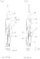
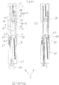
- the ejection device 1 according to the first exemplary embodiment can be seen in an exploded view.
- This ejection device 1 has a carrier 3 as a base element, via which the ejection device 1 is mounted on the piece of furniture 21 . Together with a cover that is not shown, this carrier 3 can form a housing for the remaining components of the ejection device 1 .
- the clamping element 7 is slidably mounted. The displacement movement of this tensioning element 7 is dampened by the damping device 36 .
- the restoring force accumulator 15 acts on the clamping element 7 on the one hand and on the carrier 3 on the other hand.
- the clamping element 7 forms the clamping device 6 together with the movement transmission element 8 designed as a stop.
- the ejection force accumulator 5 designed as a tension spring engages on the one hand via the ejection element force storage base 29 on the ejection element 4 and on the other hand on the carrier force storage base 32 of the carrier 3 .
- the deflection element 38 is mounted pivotably on the tensioning element 7 via the pivot bearing pin 58 . Between the deflection element 38 and the tensioning element 7 there is also a deflection force accumulator 39 designed as a tension spring.
- a coupling device 26 is also provided. This coupling device 26 is mainly formed by the coupling piece 25 and the coupling counterpart 24 .
- the coupling piece 25 is slidably mounted in the guide track 28 of the tensioning element 7 .
- the coupling and decoupling element 27 is also displaceably arranged in this guideway 28 .
- a coupling lever 41 is provided, which is rotatably mounted in the pivot bearing 44 of the tensioning element 7 and on the one hand is guided in the slot 48 of the coupling piece 25 and on the other hand is articulated to one end of the coupling counterpart stop 43 .
- a coupling force accumulator 40 designed as a tension spring, which acts on the coupling and decoupling element 27 on the one hand and on the coupling piece 25 on the other hand.
- a coupling lever force accumulator 42 also designed as a tension spring, is provided. This coupling lever force accumulator 42 engages on the one hand on the coupling lever 41 and on the other hand on the tensioning element 7 .
- a head part 37 that can be connected to the carrier 3 is provided.
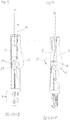
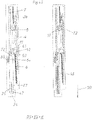
- the ejection device 1 according to the first exemplary embodiment can be seen in the assembled state.
- the carrier-energy storage base 32 and the ejector-energy storage base 29 lie in a plane containing the axis of rotation X of the ejector element 4 and the line of action W.
- the stop 45 formed on the coupling and decoupling element 27 can also be seen.
- the ejection element 4 bears against the triggering device 35 designed as a stop on the clamping element 7 .
- In 4 12 is a plan view of the ejection device 1 according to FIG 3 shown.
- the coupling counterpart 24 attached to the movable furniture part 2 represents the position of the movable furniture part 2. Accordingly, the movable furniture part 2 is in a closed position SS.
- the locking device 17 is in the locking position VS, in which the line of action W of the ejection force storage device 5 passes through the axis of rotation X leads.
- the direction of action of the line of action W is indicated by the arrow and points in the closing direction SR. Since this line of action W runs through the axis of rotation X, the force of the tensioned ejection force accumulator 5 cannot unfold. As a result, the ejection element 4 is held at a dead center, so to speak.
- the carrier energy store base 32 including the carrier 3
- the ejection force store 5 and the ejection element 4 together form the locking device 17.
- the coupling device 26 is in the coupling position K, since the coupling piece 25 is coupled to the coup
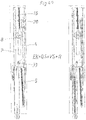
- this movable furniture part 2 reaches the overpressing position ÜS according to FIG figure 5 .
- the clamping element 7 is also moved in the closing direction SR via the coupling counterpart 24, as a result of which the stop of the triggering device 35 rotates the ejection element 4 in the direction of rotation D—that is, counterclockwise—around the axis of rotation X.
- the axis of rotation X and the line of action W reach a relative unlocking position ES that is spaced apart from one another.
- the locking device 17 is unlocked.
- the ejection force accumulator 5 can relax, as a result of which the ejection element 4 continues to rotate in the direction of rotation D (see 6 ).
- the end of the ejection element 4 facing away from the ejection element energy storage base 29 comes into contact with the ejection stop 46 formed on the clamping element 7.
- the entire clamping element 7 is moved in the opening direction OR relative to the carrier 3, which in turn causes the movable furniture part 2 to , albeit still minor, open position OS arrives.
- the ejection element 4 also pivots the deflection element 38 in a clockwise direction against the force of the deflection force accumulator 39.
- the ejection force accumulator 5 has relaxed even further, as a result of which the furniture part 2 (represented by the coupling counterpart 24) has been moved even further into the open position OS.
- the movable furniture part 2 is thus indirectly ejected from the ejection element 4 via the clamping element 7 and the coupling piece 25 . Since the tensioning element 7 moves in the opening direction OR, the restoring force accumulator 15, which is designed as a tension spring, also begins to tension.
- the end of the ejection element-power storage base 29 facing away from the Ejection element 4 again opposite (ie in this case to the right) moves.
- the deflection force accumulator 39 can also relax again, as a result of which the deflection element 38 follows the ejection element 4 .
- the ejection device 1 In between 9 and 10 the ejection device 1 reaches a position, not shown, in which the dead center opposite the locking position VS is reached, in which the carrier energy storage base 32, the ejection element energy storage base 29 and the axis of rotation X lie in one line in plan view. However, so that the ejection element 4 continues to move, starting from this neutral position or dead center position, the deflection force accumulator 39 relaxes further, as a result of which the deflection element 38 moves the ejection element 4 into the position according to FIG 10 emotional. In this position, the ejection path A of the ejection device 1 is complete. From this position, the tensioning path S begins, in which the movable furniture part 2 is actively pulled.
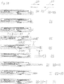
- the ejection element 4 Since the clamping element 7 is coupled to the movable furniture part 2 via the coupling device 26, the ejection element 4 is also 11 moves in the opening direction OR via the movement transmission element 8 designed as a stop. As a result, when the ejection force accumulator 5 is tensioned, the ejection element 4 is rotated in the same direction of rotation D (counterclockwise) as when the movable furniture part 2 was ejected.
- the ejection element 4 has rotated even further in the direction of rotation D about the axis of rotation X by the movement transmission element 8 .
- the tip 47 of the coupling and decoupling element 27 is located still in the foremost area of the coupling piece 25, as a result of which the head area of the coupling piece 25 is still spread or the two extensions of the head area spaced apart by a gap cannot bend towards one another.
- the coupling position K between the head area of the coupling piece 25 and the receiving area of the coupling counterpart 24 is given by a form-fitting hold.
- the decoupling position EK is reached and there is only a loose connection between the head area of the coupling piece 25 and the receiving area of the coupling counterpart 24 .
- the coupling force accumulator 40 also tensions since it acts on the coupling piece 25 on the one hand and on the coupling and decoupling element 27 on the other.
- the coupling counterpart 24 As soon as the coupling counterpart 24 has completely detached from the coupling piece 25, the movable furniture part 2 is in a freewheel state. At the same time, the coupling force accumulator 40 can relax again, as a result of which the coupling piece 25 is moved in the closing direction SR relative to the tensioning element 7 . As a result, the coupling lever 41 also pivots about the pivot bearing 44. With this movement, the coupling counterpart stop 43 is also moved out of the tensioning element 7, in that the coupling lever force store 42 relaxes.
- the head area of this coupling piece 25 gets between the side walls of the coupling piece guide 49, as a result of which the parts of the head area of the coupling piece 25 which are spaced apart from one another are pressed towards one another. This allows the Do not move the tip 47 of the coupling and decoupling element 27 all the way to the front in the coupling piece 25.
- the coupling force accumulator 40 can therefore not relax completely, but only approximately half.
- the restoring force storage device 15 also begins to relax, whereby the position according to the first 17 is reached.
- the tensioning element 7 is further extended to the position according to FIG 18 drove in until finally in 19 the return position R is reached. Of 18 on 19 this return movement is damped by the damping device 36 .
- the movable furniture part 2 is still in an open position OS.
- the locking device 17 is in the locking position VS.
- the coupling counterpart 24 first comes into contact with the coupling counterpart stop 43.
- the coupling piece 25 is first moved in the opening direction OR via the rotary movement of the coupling lever 41, as a result of which the head region of the coupling piece 25, which was not initially spread, moves into the Recording area of the coupling counterpart 24 engages. Since then the coupling piece 25 is no longer kept narrowing between the side faces of the coupling piece guide 49, according to 20 the coupling force accumulator 40 is also relaxed, as a result of which the tip 47 of the coupling and decoupling element 27 has penetrated completely into the head region of the coupling piece 25 again and this spreads the head region open as a result. Thus is in 20 the coupling position K of the coupling device 26 is reached again. This 20 corresponds again to the starting position 4 .
- a piece of furniture 21 including a furniture body 22 and a movable furniture part 2 with a second exemplary embodiment of an ejection device 1 is shown.
- the movable furniture part 2 is in turn connected in an articulated manner to the furniture body 22 via hinges 23 .
- the coupling counterpart 24 of the ejection device 1 is attached to the movable furniture part 2 .
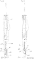
- the second exemplary embodiment of the ejection device 1 can be seen in detail.
- a carrier 3 which, together with a cover (not shown), can form a housing for the remaining components of the ejection device 1 .
- the clamping element 7 is slidably mounted. This tensioning element 7 is mounted on the carrier 3 so that it can move in a damped manner via the damping device 36 .
- the clamping element 7 is connected to the carrier 3 via the return force accumulator 15 .
- a guide track 28 for the coupling and decoupling element 27 is provided in the tensioning element 7 .
- This coupling and decoupling element 27 is pretensioned by a coupling force accumulator 40 in the left direction relative to the tensioning element 7 .
- the coupling force accumulator 40 is designed as an approximately V-shaped tension spring, the ends of this tension spring being held in the tensioning element 7 and bearing against the coupling and decoupling element 27 in a central area.
- a coupling element tensioner 56 connected to the carrier 3 is provided, which can be placed against the stop 45 of the coupling and decoupling element 27 .
- a head part 37 is also attached to the carrier 3 in this exemplary embodiment.
- a total of three ejection stops 46 are provided on the clamping element 7 , which correspond to the ejection rollers 51 arranged on the ejection element 4 .
- the ejection element 4 itself is rotatably mounted on the pivot bearing 57 of the carrier 3 via the axis of rotation X.
- the tensioning roller 52 is arranged on the ejection element 4 .
- An eccentric bolt 50 is arranged eccentrically on the ejection element 4 .
- the ejection force accumulator 5 is connected on the one hand to the ejection element 4 via the ejection element force storage base 29 and on the other hand to the carrier 3 via the carrier force storage base 32 .
- a triggering device 35 is also provided, which is formed by the triggering element 55, the triggering spring 54 and the triggering clip 53 in this exemplary embodiment. This release bar 53 is held in the recess 60 of the carrier 3 .
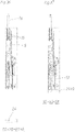
- the second exemplary embodiment of the ejection device 1 is shown in the assembled state.
- the stop 45 of the coupling and decoupling element 27 is in contact with the coupling element tensioner 56 .
- the carrier energy storage base 32 and the ejection element energy storage base 29 lie in the illustrated locking position VS in a plane containing the axis of rotation X of the ejection element 4 and the line of action W.
- one to 23 suitable plan view of the ejection device 1 is in 24 shown.
- the position of the coupling counterpart 24 corresponds to the position of the movable furniture part 2, which is in the closed position SS.
- the locking device 17 is in the locking position VS, since the line of action W of the ejection force accumulator 5 passes through the axis of rotation X.
- the front side of the release bar 53 rests against the eccentric pin 50 .
- an end area of the triggering element 55 bears against the knee area of this triggering clip 53 .
- the other end of this triggering element 55 rests against the coupling counterpart 24 .
- the head area of the coupling piece 25 is spread by the tip 47 of the coupling and decoupling element 27, but since the head area of the coupling piece 25 is not in the receiving area of the coupling counterpart 24, the coupling device 26 is still in a decoupling position EK.
- the movable furniture part 2 reaches the overpressing position ÜS according to FIG 25 . Since the release element 55 rests against the coupling counterpart 24 and the flexible release bracket 53 rests against the release element 55 via its knee area, the end face of the release bracket 53 is pressed onto the eccentric pin 50, as a result of which the ejection element 4 is rotated in the direction of rotation D about the axis of rotation X. As a result, the axis of rotation X and the line of action W reach a mutually spaced, relative unlocking position ES. Thus, the locking device 17 is unlocked.
- the ejector element energy storage base 29 is always moved for locking.
- the axis of rotation X it would also be possible for the axis of rotation X to be displaced when overpressing in such a way that it moves at a distance from the line of action W. As a result, the line of action W would remain in Relative to beam 3 unchanged, but the axis of rotation X would move relative to beam 3.
- the movable furniture part 2 is in an open position OS, albeit slightly open.
- the locking device 17 is in an unlocked position ES.
- the coupling device 26 is still in a decoupling position EK.
- the clamping element 7 has already been moved slightly in the opening direction OR relative to the carrier 3.
- the coupling element tensioner 56 is fastened to the carrier 3 and the stop 45 rests against this coupling element tensioner 56, the coupling and decoupling element 27 forming the control device does not move with the tensioning element 7 in the opening direction OR.
- the tip 47 of the coupling and decoupling element 27 moves away from the head area of the coupling piece 25.
- the head area of the coupling piece 25 is thus spread less.
- the tip 47 is retracted even further relative to the coupling piece 25, the head area of the coupling piece 25 is no longer spread and this head area can slide into the receiving area in the coupling counterpart 24 due to the mutually bendable design of its two extensions. As a result, however, only a loose connection between the coupling piece 25 and the coupling counterpart 24 is achieved.
- the coupling force accumulator 40 tensioned.
- the ejector element 4 has also already rotated further, as a result of which a second ejector roller 41 comes into contact with a second ejector stop 46 .
- the clamping element 7 is moved further in the opening direction OR relative to the carrier 3 . Since a third ejection roller 51 is still in contact with a third ejection stop 46, the ejection element 4 is also rotated further in the same direction of rotation D as when the movable furniture part 2 was ejected during this tensioning of the ejection energy store 5. At the same time, the tensioning roller 52 also comes into contact with the movement transmission element 8. This movement transmission element 8, designed as a stop, together with the tensioning element 7, forms the tensioning device 6 for the ejection force accumulator 5. This is in 30 already partly excited again.
- the movable furniture part 2 was moved even further in the opening direction OR and at the same time the ejection element 4 was rotated further in the direction of rotation D, as a result of which the eccentric pin 50 rests against a flank of the release clip 53 and this release clip 53 already bends slightly to the right due to its flexibility, as is well known in the The detailed section shown at the top right can be seen.
- this coupling and decoupling element 27 is also moved relative to the tensioning element 7 under the charge of the coupling energy store 40, as a result of which the tip 47 of the coupling and decoupling element 27 comes out of the head area of the coupling piece 25 and no longer spreads the extensions of this head area. As a result, the decoupling position EK of the coupling device 26 is reached. However, there is still a loose connection between the head area of the coupling piece 25 and the receiving area of the coupling counterpart 26 .
- the restoring force accumulator 15 can also relax again and initially moves the tensioning element 7 in the closing direction SR until the position according to FIG Figure 35 . Simultaneously with this movement or from the point in time at which the stop 45 is no longer in contact with the head part 37, the coupling force accumulator 40 can also relax. As a result, the tip 47 of the coupling and decoupling element 27 is moved into the head region of the coupling piece 25, as a result of which it is spread again.
- FIG. 38 shows a piece of furniture 21 with a furniture body 22 and a movable furniture part 2 in the form of a furniture door.
- the movable furniture part 2 is pivotably mounted on the furniture body via two hinges 23 .
- a pull-in device (not shown) for the movable furniture part 2 can be integrated into one of these hinges 23 .
- An ejection device 1 is arranged at a distance from the hinge on the furniture body 22 . In this case it can be seen that the ejection device 1 has a coupling piece 25 at its end facing the movable furniture part 2 .
- This coupling piece 25 can be coupled to a coupling counterpart 24 arranged on the movable furniture part.
- this 38 is the movable furniture part 2 in the open position OS.
- FIG 39 an exploded view of the ejection device 1 is shown.
- This ejection device 1 has the carrier 3 as the base part. Together with a cover (not shown), this can form a housing for all the components of the ejection device 1 .
- a link track 18 for the ejection element 4 is formed in the carrier 3 .
- the control lever 19 is rotatably mounted on the ejection element 4 via the control lever pivot bearing 31 .
- the control pin 20 is in turn arranged on this control lever 19 and engages in the cardioid link path 18 .
- a guide track 34 for the tensioning element 7 is formed in the carrier 3 .
- the coupling piece 25 is arranged, which forms the coupling device 26 together with the coupling counterpart 24 .
- Coupling and decoupling element 27 is provided with the coupling force accumulator 40 .
- This coupling force accumulator 40 designed as an approximately V-shaped tension spring, is Figure 39 not marked, but off Figure 41 apparent.
- the guide track 28 for the coupling and decoupling element 27 is formed in the carrier 3 .
- a bolt 61 is provided for the coupling and decoupling element 27 , which is rotatably mounted in the bearing 62 and has a receiving trough 63 for the extension 64 formed on the coupling and decoupling element 27 .
- the bolt stop 65 is held in the recesses 67 in the carrier 3 via the bolts 66 .
- the ejection force store 5 is connected to the ejection element 4 via the spring base 29 on the one hand and acts on the spring base 30 formed in the carrier 3 on the other hand.
- the spring base 29 is connected in an articulated manner to the ejection element 4 via the bolt 68 .
- a further control pin 69 is held in the spring base 29 , which enables the spring base 29 to be guided in a targeted manner in the region 70 of the link track 18 .
- a toothed rack 12 is also formed on the ejection element 4 .
- the clamping element 7 is movably coupled to the movement transmission element 8 .
- this movement transmission element 8 is designed as a gear wheel 10 which meshes with the toothed rack 11 of the tensioning element 7 and the toothed rack 12 of the ejection element 4 .
- the movement transmission element 8 is slidably mounted on the one hand in the guideway 9 formed in the carrier 3 and on the other hand is rotatably mounted in the carriage 16 .
- the guide track 9 has two end stops E1 and E2.
- the slide 16 in turn is part of the return device 13 for the tensioning element 7.
- the return force accumulator 15 acts on this slide 16.
- this restoring force store 15 is attached at the other end to the spring base 32 formed in the carrier 3 .
- the ejection device 1 is shown in the assembled state.
- the coupling piece 25 is loosely connected to the coupling counterpart 24 .
- the clamping element 7 forms the clamping device 6 together with the movement transmission element 8 .
- this movement transmission element 8 forms the restoring element 14 at the same time as the carriage 16.
- the return force accumulator 15 which in this case as a spring, in particular as a tension spring, is trained - in a relaxed position.
- the ejection force accumulator 5 which is also designed as a spring, in particular as a tension spring, is in the tensioned position.
- the control pin 20 of the locking device 17 is located in the detent trough of the heart-shaped link track 18, whereby the entire ejection device 1 is in the locking position VS.
- FIG. 41 to 49 a top view of the ejection device 1 is shown in different positions on the left side. The same plan view is shown on the right-hand side, but the underlying components, which are actually not visible, are also indicated by dashed lines.
- the ejection device 1 is in the same position as in figure 40 , namely in the locked position VS.
- the movable furniture part 2 is in the closed position SS.
- This closed position SS is represented by the coupling counterpart 24 , which is attached to the movable furniture part 2 .
- the clamping element 7 rests against the ejection element 4 via the buffer element 33 .
- the control pin 20 arranged on the control lever 19 is located in the detent trough of the heart-shaped link track 18 of the locking device 17.
- the ejection force store 5 is tensioned, while the return force store 15 is relaxed.
- the bolt 61 encompasses the extension 64 via its receiving trough 63, as a result of which the coupling and decoupling element 27 is located with its tip 47 in a retracted position toward the head region of the coupling piece 25.
- the coupling force accumulator 40 is tensioned.
- the coupling force accumulator 40 is held with its two ends in the tensioning element 7 and rests on the coupling and decoupling element 27 in a central area.
- the coupling device 26 is in the decoupling position EK, in which the coupling piece 25 and the coupling counterpart 24 are loosely connected to one another.
- the ejection device 1 reaches the overpressure position ÜS according to FIG Figure 42 .
- the clamping element 7 is moved in the closing direction SR via the coupling counterpart 24 and the coupling piece 25 as a result of this overpressing movement.
- the ejection element 4 is moved against the force of the ejection force accumulator 5 in the closing direction SR, as a result of which the control lever 19 and, above all, its control pin 20 moves out of the detent recess of the heart-shaped link path 18 via a corresponding deviating slope into an ejection section of the link path 18.
- the ejection element 4 is no longer locked on the carrier 3 via the locking device 17 but is in an unlocked position ES. It can also be seen on the right that the movement transmission element 8 was also moved up to the end stop E2 of the guide track 9 with this over-pressing movement. With this overpressing movement, the bar 61 was also moved relative to the bar stop 65, with the extension 71 of the bar 61 moving past the flexible end 72 of the bar stop 65--in the case of a lateral loading direction.
- the ejection force accumulator 5 can relax.
- the ejection device 1 first reaches the position according to FIG Figure 43 , which corresponds to a slight open position of the movable furniture part 2 OS. It can be seen that, in its unlocked position ES, the control pin 20 has already moved slightly in the opening direction OR through the ejection section of the link track 18 . Since the ejection force accumulator 5 pulls on the ejection element 4, this ejection element 4 also moves in the opening direction OR relative to the carrier 3. Since the ejection element 4 also rests against the clamping element 7 via the buffer element 33, this clamping element 7 also moves in the opening direction OR.
- the movement transmission element 8 Since, moreover, the movement transmission element 8 is slidably mounted in the guide track 9, the ejection element 4, the movement transmission element 8 and the tensioning element 7 are moved together relative to the carrier 3 over this first part of the ejection path A.
- This movement of the tensioning element 7 in the opening direction OR also takes along the bolt 61 arranged thereon, as a result of which the extension 71 rests against the rigid end 72 of the bolt stop 65--in this face-side opening direction. This initiates a clockwise rotation of the bolt 61 about the bearing 62 . As a result, the extension 64 is no longer held in the receiving recess 63 of the bolt 61 .
- the tensioning element 7 together with the movement transmission element 8 forms the tensioning device 6 for the ejection force accumulator 5.
- This ejection force accumulator 5 is in Figure 45 and also in the Figure 46 , 47 and 50 (Partly) shown purely schematically as a solid line to illustrate the length.
- the extension 64 which at the same time forms a stop 45 for the coupling and decoupling element 27 , rests on the carrier 3 .
- the predetermined opening path VO is reached. If the movable furniture part 2 is now pulled further in the opening direction OR, the coupling and decoupling element 27 cannot move with the clamping element 7 that also forms the coupling piece 25 .
- the ejection force storage device 5 can relax again briefly and easily until according to Figure 47 the control pin 20 is locked in the detent recess of the heart-shaped link track 18. As a result, the locking position VS of the locking device 17 or the ejection element 4 is reached again.
- figure 50 are clear the individual positions according to the Figures 41 to 49 shown again in sequence. Comparing the third picture with the fourth picture of this one figure 50 It can be seen how, according to the invention, the ejection element 4, the movement transmission element 8 and the tensioning element 7 can be moved together over the ejection path A relative to the carrier 3.
- the fourth variant of the coupling device 26 can be used in the same way in the ejection devices 1 according to the first three exemplary embodiments.
- the only essential difference is that during the decoupling movement, the coupling and decoupling element 27 is moved relative to the coupling piece 25 in the opening direction OR and not in the closing direction SR.
- FIG 51a shows a side view of a coupling device 26 without the remaining parts of an ejection device 1.
- This coupling device 26 according to FIG Figure 51a is in the coupling position K.
- the coupling piece 25 has a coupling front part 74 , a coupling housing 75 and a coupling rear part 76 .
- the coupling and decoupling element 27 is guided in this coupling piece 25 .
- the first coupling arm 77 is articulated on the rear coupling part 76 .
- This first coupling arm 77 is connected in an articulated manner to the second coupling arm 79 via the rotary joint 78 .
- This second coupling arm 79 is in turn connected to the coupling and decoupling element 27 in an articulated manner.
- the coupling piece 25 has two spaced-apart extensions in its head area.
- a spreading element 73 which rests with its spreading surfaces on the inner surfaces of the extensions of the head region of the coupling piece 25 and presses them apart.
- these extensions rest against corresponding mating surfaces in the receiving area of the coupling counterpart 24 and there is a form-fitting hold.
- the coupling device 26 has been switched as a function of the opening path O by the control device.
- the second coupling arm 79 has been pivoted via a stop, not shown (e.g. in the area of the furniture body 22 or the support 3), so that the coupling and decoupling element 27 is in the opening direction relative to the coupling piece 25 OR was pushed.
- a stop not shown (e.g. in the area of the furniture body 22 or the support 3)
- the coupling and decoupling element 27 is in the opening direction relative to the coupling piece 25 OR was pushed.
- the decoupling position EK of the coupling device 26 has been reached.
- the tensioning element 7 together with the movement transmission element 8 forms the tensioning device 6 for the ejection force accumulator 5.
- This ejection force accumulator 5 is in Figure 45 and also in the Figure 46 , 47 and 50 (Partly) shown purely schematically as a solid line to illustrate the length.
- the extension 64 which at the same time forms a stop 45 for the coupling and decoupling element 27 , rests on the carrier 3 .
- the predetermined opening path VO is reached. If the movable furniture part 2 is now pulled further in the opening direction OR, the coupling and decoupling element 27 cannot move with the clamping element 7 that also forms the coupling piece 25 .
- the ejection force storage device 5 can relax again briefly and easily until according to Figure 47 the control pin 20 is locked in the detent recess of the heart-shaped link track 18. As a result, the locking position VS of the locking device 17 or the ejection element 4 is reached again.
- figure 50 are clear the individual positions according to the Figures 41 to 49 shown again in sequence. Comparing the third picture with the fourth picture of this one figure 50 It can be seen how, according to the invention, the ejection element 4, the movement transmission element 8 and the tensioning element 7 can be moved together over the ejection path A relative to the carrier 3.
- the fourth variant of the coupling device 26 can be used in the same way in the ejection devices 1 according to the first three exemplary embodiments.
- the only essential difference is that during the decoupling movement, the coupling and decoupling element 27 is moved relative to the coupling piece 25 in the opening direction OR and not in the closing direction SR.
- FIG 51a shows a side view of a coupling device 26 without the remaining parts of an ejection device 1.
- This coupling device 26 according to FIG Figure 51a is in the coupling position K.
- the coupling piece 25 has a coupling front part 74 , a coupling housing 75 and a coupling rear part 76 .
- the coupling and decoupling element 27 is guided in this coupling piece 25 .
- the first coupling arm 77 is articulated on the rear coupling part 76 .
- This first coupling arm 77 is connected in an articulated manner to the second coupling arm 79 via the rotary joint 78 .
- This second coupling arm 79 is in turn connected to the coupling and decoupling element 27 in an articulated manner.
- the coupling piece 25 has two spaced-apart extensions in its head area.
- a spreading element 73 is arranged, which with its spreading surfaces on the inner surfaces of the extensions of the head area of the Coupling piece 25 is applied and this pushes apart. As a result, these extensions rest against corresponding mating surfaces in the receiving area of the coupling counterpart 24 and there is a form-fitting hold.
- the coupling device 26 has been switched as a function of the opening path O by the control device.
- the second coupling arm 79 has been pivoted via a stop, not shown (e.g. in the area of the furniture body 22 or the support 3), so that the coupling and decoupling element 27 is in the opening direction relative to the coupling piece 25 OR was pushed.
- a stop not shown (e.g. in the area of the furniture body 22 or the support 3)
- the coupling and decoupling element 27 is in the opening direction relative to the coupling piece 25 OR was pushed.
- the decoupling position EK of the coupling device 26 has been reached.
Claims (13)
- Dispositif d'éjection (1) pour éjecter une partie de meuble (2) mobile depuis une position de fermeture (SS) le long d'un trajet d'ouverture (0) dans une position ouverte (OS), avec- un support (3) et- un dispositif de couplage (26) pour coupler le dispositif d'éjection (1) à la partie de meuble (2) mobile, dans lequel le dispositif de couplage (26) présente une pièce de couplage (25) mobile par rapport au support (3) et une contre-pièce de couplage (24) pouvant être disposée sur la partie de meuble (2) mobile ou sur un corps de meuble (22), dans lequel le dispositif de couplage (26) présente une position de couplage (K) et une position de découplage (EK) et le dispositif d'éjection (1) peut être couplé à la partie de meuble (2) mobile par l'intermédiaire du dispositif de couplage (26) se trouvant dans la position de couplage (K),caractérisé par- un dispositif de commande, par lequel le dispositif de couplage (26) peut être commuté en fonction du trajet d'ouverture (0), dans lequel le dispositif de couplage (26) parvient depuis la position de couplage (K) dans la position de découplage (EK) pour un trajet d'ouverture (VO) prédéfini, dans lequel le dispositif de commande présente un élément de couplage et de découplage (27) mobile par rapport à la pièce de couplage (25), dans lequel au moins une zone de tête de la pièce de couplage (25) peut être écartée par l'élément de couplage et de découplage (27) et la position de découplage (EK) entre la pièce de couplage (25) et la contre-pièce de couplage (24) est donnée lorsque la zone de tête de la pièce de couplage (25) n'est pas écartée en ce qu'une liaison lâche est présente entre la zone de tête de la pièce de couplage (25) et la zone de logement de la contre-pièce de couplage (24).
- Dispositif d'éjection selon la revendication 1, caractérisé en ce qu'un maintien par complémentarité de forme est présent dans la position de couplage (K) entre la pièce de couplage (25) et la contre-pièce de couplage (24), dans lequel ledit maintien par complémentarité de forme peut être annulé par le dispositif de commande.
- Dispositif d'éjection selon la revendication 1 ou 2, caractérisé en ce que l'élément de couplage et de découplage (27) peut être déplacé dans une piste de guidage (28) dans le support (3) ou dans un élément de serrage (7).
- Dispositif d'éjection selon l'une quelconque des revendications 1 à 3, caractérisé en ce que la pièce de couplage (25) peut être déplacée par rapport au support (3) conjointement avec l'élément de couplage et de découplage (27) pendant le déplacement d'ouverture jusqu'à atteindre le trajet d'ouverture (VO) prédéfini et, une fois le trajet d'ouverture (VO) prédéfini atteint, d'une part l'élément de couplage et de découplage (27) est immobilisé par rapport au support (3) et d'autre part la pièce de couplage (25) peut être déplacée par rapport à l'élément de couplage et de découplage (27), dans lequel l'élément de couplage et de découplage (27) présente une butée (45), par l'intermédiaire de laquelle l'élément de couplage et de découplage (27) se trouve sur le support (3), de préférence sur une partie de tête (37) du support (3) lorsque le trajet d'ouverture (VO) prédéfini est atteint.
- Dispositif d'éjection selon l'une quelconque des revendications 1 à 4, caractérisé en ce que lorsque la zone de tête de la pièce de couplage (25) est écartée, la position de couplage (K) entre la pièce de couplage (25) et la contre-pièce de couplage (24) est donnée en ce qu'un maintien par complémentarité de forme est présent entre la zone de tête de la pièce de couplage (25) et une zone de logement de la contre-pièce de couplage (24).
- Dispositif d'éjection selon l'une quelconque des revendications 1 à 5, caractérisé par un élément d'éjection (4) pour éjecter la partie de meuble (2) mobile hors de la position de fermeture (SS) dans une position ouverte (OS) et un accumulateur de force d'éjection (5) soumettant à l'action d'une force l'élément d'éjection (4) dans la direction d'ouverture (OR) de la partie de meuble (2) mobile.
- Dispositif d'éjection selon la revendication 6, caractérisé par un dispositif de verrouillage (17) pour verrouiller l'élément d'éjection (4) dans une position de verrouillage (VS), dans lequel le dispositif de verrouillage (17) peut être déverrouillé dans une position de surpression (ÜS) située après la position de fermeture (SS) par surpression de la partie de meuble (2) mobile.
- Dispositif d'éjection selon la revendication 6 ou 7, caractérisé par un dispositif de serrage (6) pour serrer l'accumulateur de force d'éjection (5), de préférence en tirant sur la partie de meuble (2) mobile dans la direction d'ouverture (OR).
- Dispositif d'éjection selon la revendication 8, caractérisé en ce que la pièce de couplage (25) du dispositif de couplage (26) est reliée au dispositif de serrage (6), de préférence est réalisée d'un seul tenant avec un élément de serrage (7) du dispositif de serrage (6).
- Dispositif d'éjection selon la revendication 8 ou 9, caractérisé par un dispositif de rappel (13) avec un accumulateur de force de rappel (15) pour déplacer le dispositif de serrage (6) dans une position de rappel (R) .
- Meuble (21) avec un corps de meuble (22), une partie de meuble (2) mobile et un dispositif d'éjection (1) selon l'une quelconque des revendications 1 à 10 pour la partie de meuble (2) mobile.
- Meuble selon la revendication 11, caractérisé en ce que le dispositif d'éjection (1) est couplé à la partie de meuble (2) mobile par l'intermédiaire du dispositif de couplage (26) se trouvant dans la position de couplage (K).
- Meuble selon la revendication 11 ou 12, caractérisé en ce que la partie de meuble (2) mobile est débloquée par le dispositif de couplage (26) dans la position de découplage (EK).
Priority Applications (2)
| Application Number | Priority Date | Filing Date | Title |
|---|---|---|---|
| EP22181817.2A EP4086419A1 (fr) | 2015-06-09 | 2016-05-17 | Dispositif d'éjection pour un élément mobile de meuble |
| SI201631605T SI3307975T1 (sl) | 2015-06-09 | 2016-05-17 | Izmetna naprava za gibljiv pohištveni del |
Applications Claiming Priority (2)
| Application Number | Priority Date | Filing Date | Title |
|---|---|---|---|
| ATA358/2015A AT516391B1 (de) | 2015-06-09 | 2015-06-09 | Ausstoßvorrichtung für ein bewegbares Möbelteil |
| PCT/AT2016/050141 WO2016197162A1 (fr) | 2015-06-09 | 2016-05-17 | Dispositif d'éjection d'une partie de meuble mobile |
Related Child Applications (1)
| Application Number | Title | Priority Date | Filing Date |
|---|---|---|---|
| EP22181817.2A Division EP4086419A1 (fr) | 2015-06-09 | 2016-05-17 | Dispositif d'éjection pour un élément mobile de meuble |
Publications (2)
| Publication Number | Publication Date |
|---|---|
| EP3307975A1 EP3307975A1 (fr) | 2018-04-18 |
| EP3307975B1 true EP3307975B1 (fr) | 2022-07-06 |
Family
ID=55907748
Family Applications (2)
| Application Number | Title | Priority Date | Filing Date |
|---|---|---|---|
| EP22181817.2A Pending EP4086419A1 (fr) | 2015-06-09 | 2016-05-17 | Dispositif d'éjection pour un élément mobile de meuble |
| EP16735565.0A Active EP3307975B1 (fr) | 2015-06-09 | 2016-05-17 | Dispositif d'éjection d'une partie de meuble mobile |
Family Applications Before (1)
| Application Number | Title | Priority Date | Filing Date |
|---|---|---|---|
| EP22181817.2A Pending EP4086419A1 (fr) | 2015-06-09 | 2016-05-17 | Dispositif d'éjection pour un élément mobile de meuble |
Country Status (8)
| Country | Link |
|---|---|
| US (1) | US10676976B2 (fr) |
| EP (2) | EP4086419A1 (fr) |
| JP (1) | JP6545291B2 (fr) |
| CN (1) | CN107849886B (fr) |
| AT (2) | AT516391B1 (fr) |
| ES (1) | ES2928025T3 (fr) |
| SI (1) | SI3307975T1 (fr) |
| WO (1) | WO2016197162A1 (fr) |
Families Citing this family (8)
| Publication number | Priority date | Publication date | Assignee | Title |
|---|---|---|---|---|
| AT516812B1 (de) * | 2015-01-29 | 2019-11-15 | Blum Gmbh Julius | Antriebsvorrichtung für ein bewegbares Möbelteil |
| AT517243B1 (de) * | 2015-06-09 | 2017-02-15 | Blum Gmbh Julius | Ausstoßvorrichtung für ein bewegbares Möbelteil |
| AT517343B1 (de) * | 2015-06-29 | 2017-01-15 | Blum Gmbh Julius | Ausstoßvorrichtung für eine Falttür oder Falt-Schiebe-Tür |
| US11486181B2 (en) * | 2018-06-13 | 2022-11-01 | Wolfgang Held | Device for opening and closing supported covers |
| CN109763733B (zh) * | 2018-12-29 | 2020-07-14 | 广东炬森五金精密制造有限公司 | 一种开门器 |
| WO2020246974A1 (fr) * | 2019-06-05 | 2020-12-10 | Knape & Vogt Manufacturing Company | Dispositif de fermeture pour tiroirs |
| GB2595273A (en) * | 2020-05-20 | 2021-11-24 | Titus D O O Dekani | Movement control device |
| CN112223230B (zh) * | 2020-11-11 | 2021-08-20 | 杭州鎏金庐亮空间设计有限公司 | 一种自动闭门安全工具柜 |
Citations (1)
| Publication number | Priority date | Publication date | Assignee | Title |
|---|---|---|---|---|
| EP2307829B1 (fr) * | 2008-05-02 | 2013-11-06 | Arçelik Anonim Sirketi | Mécanisme d'ouverture-fermeture de porte utilisé dans des dispositifs de refroidissement |
Family Cites Families (23)
| Publication number | Priority date | Publication date | Assignee | Title |
|---|---|---|---|---|
| AT8629B (de) | 1901-12-16 | 1902-08-11 | Carl Toenjes | Vorrichtung zur Erzeugung durchgehender Farbmuster in Linoleum oder anderen Stoffen. |
| US3551963A (en) * | 1968-08-16 | 1971-01-05 | Walter W Mosher Jr | Self-locking snap fastener |
| IT1037430B (it) * | 1975-04-18 | 1979-11-10 | Stefani Spa G | Gruppo intestatore per rannelli di legno massicci truciolari o di alttro tipo |
| JPS5788861U (fr) * | 1980-11-18 | 1982-06-01 | ||
| JPS5788861A (en) | 1980-11-22 | 1982-06-02 | Fuji Electric Co Ltd | Rotary rectifier |
| DE59301773D1 (de) * | 1992-07-08 | 1996-04-11 | Klessmann Ima Norte Maschfab | Durchlaufmaschine zur Bearbeitung von Kantenstreifen plattenförmiger Werkstücke |
| DE10047385C2 (de) * | 2000-09-25 | 2002-10-17 | Homag Maschinenbau Ag | Verfahren und Vorrichtung zur Bearbeitung von fortlaufend bewegten Werkstücken |
| ITMI20040198U1 (it) * | 2004-04-30 | 2004-07-30 | Agostino Ferrari Spa | Anta con apertura a pressione |
| AT413472B (de) * | 2004-08-16 | 2006-03-15 | Blum Gmbh Julius | Ausstossvorrichtung für ein bewegbares möbelteil |
| AT8629U1 (de) * | 2004-09-13 | 2006-10-15 | Blum Gmbh Julius | Möbel mit einem bewegbaren möbelteil |
| JP4481139B2 (ja) * | 2004-10-08 | 2010-06-16 | スガツネ工業株式会社 | 扉用ラッチ |
| DE202005002433U1 (de) * | 2005-02-14 | 2005-05-19 | Grass Gmbh | Touch-Latch System für Möbel mit zueinander relativ bewegbaren Möbelteilen, insbesondere Möbelschubladen, Möbeltüren oder Möbelklappe |
| JP2006307533A (ja) * | 2005-04-28 | 2006-11-09 | Systec Kyowa:Kk | 耐震ロック機構付きプッシュラッチ装置 |
| US20070113483A1 (en) * | 2005-11-22 | 2007-05-24 | Hernandez Everardo A | Door module positioning system |
| ITRM20060162U1 (it) * | 2006-09-12 | 2008-03-13 | Salice Arturo Spa | Dispositivo di chiusura e apertura del tipo a scatto di una parte movibile di un mobile |
| DE102008030933A1 (de) * | 2008-07-02 | 2010-01-07 | Zimmer, Günther | Betätigungsvorrichtung für Möbelstückteile mit mindestens einem abkuppelbaren Formgedächtniselement |
| DE202009005009U1 (de) * | 2008-10-08 | 2010-03-04 | Paul Hettich Gmbh & Co. Kg | Öffnungs- und Schließvorrichtung für ein Schubelement |
| JPWO2010092697A1 (ja) * | 2009-02-16 | 2012-08-16 | 株式会社ニフコ | 移動体の移動装置 |
| RU2543407C2 (ru) * | 2009-08-07 | 2015-02-27 | Пауль Хеттих Гмбх Унд Ко. Кг | Выталкивающий механизм, выдвижная направляющая и выталкивающая система |
| DE102011052355B4 (de) | 2011-08-02 | 2022-04-28 | Dongtai Hardware Precision (Hong Kong) Limited | Vorrichtung zum Öffnen der Schranktüre eines Schrankkorpusses |
| AT512165B1 (de) | 2011-12-27 | 2013-06-15 | Blum Gmbh Julius | Antriebsvorrichtung für ein bewegbares möbelteil |
| AT512699B1 (de) | 2012-03-16 | 2018-12-15 | Blum Gmbh Julius | Ausstoßvorrichtung für ein bewegbares Möbelteil |
| AT514058B1 (de) | 2013-04-12 | 2014-10-15 | Blum Gmbh Julius | Antriebsvorrichtung für ein bewegbares Möbelteil |
-
2015
- 2015-06-09 AT ATA358/2015A patent/AT516391B1/de active
- 2015-12-10 AT ATA8011/2016A patent/AT517993B1/de active
-
2016
- 2016-05-17 EP EP22181817.2A patent/EP4086419A1/fr active Pending
- 2016-05-17 ES ES16735565T patent/ES2928025T3/es active Active
- 2016-05-17 CN CN201680042247.7A patent/CN107849886B/zh active Active
- 2016-05-17 JP JP2017564028A patent/JP6545291B2/ja active Active
- 2016-05-17 EP EP16735565.0A patent/EP3307975B1/fr active Active
- 2016-05-17 WO PCT/AT2016/050141 patent/WO2016197162A1/fr active Application Filing
- 2016-05-17 SI SI201631605T patent/SI3307975T1/sl unknown
-
2017
- 2017-12-08 US US15/835,937 patent/US10676976B2/en active Active
Patent Citations (1)
| Publication number | Priority date | Publication date | Assignee | Title |
|---|---|---|---|---|
| EP2307829B1 (fr) * | 2008-05-02 | 2013-11-06 | Arçelik Anonim Sirketi | Mécanisme d'ouverture-fermeture de porte utilisé dans des dispositifs de refroidissement |
Also Published As
| Publication number | Publication date |
|---|---|
| EP4086419A1 (fr) | 2022-11-09 |
| JP6545291B2 (ja) | 2019-07-17 |
| AT516391A4 (de) | 2016-05-15 |
| WO2016197162A1 (fr) | 2016-12-15 |
| AT517993A1 (de) | 2017-06-15 |
| AT516391B1 (de) | 2016-05-15 |
| CN107849886B (zh) | 2019-08-16 |
| US20180100338A1 (en) | 2018-04-12 |
| AT517993B1 (de) | 2018-01-15 |
| EP3307975A1 (fr) | 2018-04-18 |
| US10676976B2 (en) | 2020-06-09 |
| CN107849886A (zh) | 2018-03-27 |
| SI3307975T1 (sl) | 2022-11-30 |
| JP2018521243A (ja) | 2018-08-02 |
| ES2928025T3 (es) | 2022-11-14 |
Similar Documents
| Publication | Publication Date | Title |
|---|---|---|
| EP3307975B1 (fr) | Dispositif d'éjection d'une partie de meuble mobile | |
| EP2770876B1 (fr) | Verrouillage synchronisé pour une partie mobile de meuble | |
| EP3486418B1 (fr) | Dispositif d'éjection pour un élément de meuble mobile | |
| EP2256271B1 (fr) | Meuble | |
| EP2661195B1 (fr) | Dispositif d'éjection verrouillable à mécanisme de surcharge | |
| EP3282895B1 (fr) | Dispositifs d'entraînement avec dispositif de synchronisation pour une partie de meuble mobile | |
| AT512512B1 (de) | Antriebsvorrichtung für ein bewegbares Möbelteil | |
| EP1921948B1 (fr) | Dispositif de poussée pouvant être bloqué | |
| EP1314842B1 (fr) | Dispositif d'ouverture et de fermeture pour une partie de meuble mobile | |
| EP2254442B1 (fr) | Dispositif de fixation destiné à arrêter un élément de meuble logé mobile dans ou contre un meuble | |
| AT516677A1 (de) | Möbelantrieb | |
| EP3307111B1 (fr) | Dispositif d'éjection d'un élément de meuble mobile | |
| AT509923A1 (de) | Einzugsvorrichtung zum einziehen eines bewegbar gelagerten möbelteiles | |
| EP3307974B1 (fr) | Dispositif d'éjection pour élément de meuble mobile | |
| EP2694765B1 (fr) | Dispositif de rentrée | |
| EP4048122B1 (fr) | Combinaison d'un element de mouvement et d'un element de synchronisation pour des rails de tiroir | |
| EP3300628A1 (fr) | Dispositif de retraction pour un tiroir | |
| DE102021120908A1 (de) | Vorrichtung zum Bewegen eines Ausstoßers und Möbel | |
| AT9481U1 (de) | Verriegelbare ausstossvorrichtung |
Legal Events
| Date | Code | Title | Description |
|---|---|---|---|
| STAA | Information on the status of an ep patent application or granted ep patent |
Free format text: STATUS: THE INTERNATIONAL PUBLICATION HAS BEEN MADE |
|
| PUAI | Public reference made under article 153(3) epc to a published international application that has entered the european phase |
Free format text: ORIGINAL CODE: 0009012 |
|
| STAA | Information on the status of an ep patent application or granted ep patent |
Free format text: STATUS: REQUEST FOR EXAMINATION WAS MADE |
|
| 17P | Request for examination filed |
Effective date: 20171204 |
|
| AK | Designated contracting states |
Kind code of ref document: A1 Designated state(s): AL AT BE BG CH CY CZ DE DK EE ES FI FR GB GR HR HU IE IS IT LI LT LU LV MC MK MT NL NO PL PT RO RS SE SI SK SM TR |
|
| AX | Request for extension of the european patent |
Extension state: BA ME |
|
| STAA | Information on the status of an ep patent application or granted ep patent |
Free format text: STATUS: EXAMINATION IS IN PROGRESS |
|
| 17Q | First examination report despatched |
Effective date: 20180808 |
|
| DAV | Request for validation of the european patent (deleted) | ||
| DAX | Request for extension of the european patent (deleted) | ||
| STAA | Information on the status of an ep patent application or granted ep patent |
Free format text: STATUS: EXAMINATION IS IN PROGRESS |
|
| RIC1 | Information provided on ipc code assigned before grant |
Ipc: E05F 1/10 20060101ALI20211222BHEP Ipc: E05C 19/02 20060101ALI20211222BHEP Ipc: E05F 1/16 20060101AFI20211222BHEP |
|
| GRAP | Despatch of communication of intention to grant a patent |
Free format text: ORIGINAL CODE: EPIDOSNIGR1 |
|
| STAA | Information on the status of an ep patent application or granted ep patent |
Free format text: STATUS: GRANT OF PATENT IS INTENDED |
|
| INTG | Intention to grant announced |
Effective date: 20220207 |
|
| GRAS | Grant fee paid |
Free format text: ORIGINAL CODE: EPIDOSNIGR3 |
|
| GRAA | (expected) grant |
Free format text: ORIGINAL CODE: 0009210 |
|
| STAA | Information on the status of an ep patent application or granted ep patent |
Free format text: STATUS: THE PATENT HAS BEEN GRANTED |
|
| AK | Designated contracting states |
Kind code of ref document: B1 Designated state(s): AL AT BE BG CH CY CZ DE DK EE ES FI FR GB GR HR HU IE IS IT LI LT LU LV MC MK MT NL NO PL PT RO RS SE SI SK SM TR |
|
| REG | Reference to a national code |
Ref country code: AT Ref legal event code: REF Ref document number: 1503001 Country of ref document: AT Kind code of ref document: T Effective date: 20220715 Ref country code: CH Ref legal event code: EP |
|
| REG | Reference to a national code |
Ref country code: DE Ref legal event code: R096 Ref document number: 502016015044 Country of ref document: DE |
|
| REG | Reference to a national code |
Ref country code: IE Ref legal event code: FG4D Free format text: LANGUAGE OF EP DOCUMENT: GERMAN |
|
| REG | Reference to a national code |
Ref country code: LT Ref legal event code: MG9D |
|
| REG | Reference to a national code |
Ref country code: NL Ref legal event code: MP Effective date: 20220706 |
|
| REG | Reference to a national code |
Ref country code: ES Ref legal event code: FG2A Ref document number: 2928025 Country of ref document: ES Kind code of ref document: T3 Effective date: 20221114 |
|
| PG25 | Lapsed in a contracting state [announced via postgrant information from national office to epo] |
Ref country code: SE Free format text: LAPSE BECAUSE OF FAILURE TO SUBMIT A TRANSLATION OF THE DESCRIPTION OR TO PAY THE FEE WITHIN THE PRESCRIBED TIME-LIMIT Effective date: 20220706 Ref country code: RS Free format text: LAPSE BECAUSE OF FAILURE TO SUBMIT A TRANSLATION OF THE DESCRIPTION OR TO PAY THE FEE WITHIN THE PRESCRIBED TIME-LIMIT Effective date: 20220706 Ref country code: PT Free format text: LAPSE BECAUSE OF FAILURE TO SUBMIT A TRANSLATION OF THE DESCRIPTION OR TO PAY THE FEE WITHIN THE PRESCRIBED TIME-LIMIT Effective date: 20221107 Ref country code: NO Free format text: LAPSE BECAUSE OF FAILURE TO SUBMIT A TRANSLATION OF THE DESCRIPTION OR TO PAY THE FEE WITHIN THE PRESCRIBED TIME-LIMIT Effective date: 20221006 Ref country code: NL Free format text: LAPSE BECAUSE OF FAILURE TO SUBMIT A TRANSLATION OF THE DESCRIPTION OR TO PAY THE FEE WITHIN THE PRESCRIBED TIME-LIMIT Effective date: 20220706 Ref country code: LV Free format text: LAPSE BECAUSE OF FAILURE TO SUBMIT A TRANSLATION OF THE DESCRIPTION OR TO PAY THE FEE WITHIN THE PRESCRIBED TIME-LIMIT Effective date: 20220706 Ref country code: LT Free format text: LAPSE BECAUSE OF FAILURE TO SUBMIT A TRANSLATION OF THE DESCRIPTION OR TO PAY THE FEE WITHIN THE PRESCRIBED TIME-LIMIT Effective date: 20220706 Ref country code: FI Free format text: LAPSE BECAUSE OF FAILURE TO SUBMIT A TRANSLATION OF THE DESCRIPTION OR TO PAY THE FEE WITHIN THE PRESCRIBED TIME-LIMIT Effective date: 20220706 |
|
| PG25 | Lapsed in a contracting state [announced via postgrant information from national office to epo] |
Ref country code: PL Free format text: LAPSE BECAUSE OF FAILURE TO SUBMIT A TRANSLATION OF THE DESCRIPTION OR TO PAY THE FEE WITHIN THE PRESCRIBED TIME-LIMIT Effective date: 20220706 Ref country code: IS Free format text: LAPSE BECAUSE OF FAILURE TO SUBMIT A TRANSLATION OF THE DESCRIPTION OR TO PAY THE FEE WITHIN THE PRESCRIBED TIME-LIMIT Effective date: 20221106 Ref country code: HR Free format text: LAPSE BECAUSE OF FAILURE TO SUBMIT A TRANSLATION OF THE DESCRIPTION OR TO PAY THE FEE WITHIN THE PRESCRIBED TIME-LIMIT Effective date: 20220706 Ref country code: GR Free format text: LAPSE BECAUSE OF FAILURE TO SUBMIT A TRANSLATION OF THE DESCRIPTION OR TO PAY THE FEE WITHIN THE PRESCRIBED TIME-LIMIT Effective date: 20221007 |
|
| REG | Reference to a national code |
Ref country code: DE Ref legal event code: R097 Ref document number: 502016015044 Country of ref document: DE |
|
| PG25 | Lapsed in a contracting state [announced via postgrant information from national office to epo] |
Ref country code: SM Free format text: LAPSE BECAUSE OF FAILURE TO SUBMIT A TRANSLATION OF THE DESCRIPTION OR TO PAY THE FEE WITHIN THE PRESCRIBED TIME-LIMIT Effective date: 20220706 Ref country code: RO Free format text: LAPSE BECAUSE OF FAILURE TO SUBMIT A TRANSLATION OF THE DESCRIPTION OR TO PAY THE FEE WITHIN THE PRESCRIBED TIME-LIMIT Effective date: 20220706 Ref country code: DK Free format text: LAPSE BECAUSE OF FAILURE TO SUBMIT A TRANSLATION OF THE DESCRIPTION OR TO PAY THE FEE WITHIN THE PRESCRIBED TIME-LIMIT Effective date: 20220706 Ref country code: CZ Free format text: LAPSE BECAUSE OF FAILURE TO SUBMIT A TRANSLATION OF THE DESCRIPTION OR TO PAY THE FEE WITHIN THE PRESCRIBED TIME-LIMIT Effective date: 20220706 |
|
| PLBE | No opposition filed within time limit |
Free format text: ORIGINAL CODE: 0009261 |
|
| STAA | Information on the status of an ep patent application or granted ep patent |
Free format text: STATUS: NO OPPOSITION FILED WITHIN TIME LIMIT |
|
| PG25 | Lapsed in a contracting state [announced via postgrant information from national office to epo] |
Ref country code: SK Free format text: LAPSE BECAUSE OF FAILURE TO SUBMIT A TRANSLATION OF THE DESCRIPTION OR TO PAY THE FEE WITHIN THE PRESCRIBED TIME-LIMIT Effective date: 20220706 Ref country code: EE Free format text: LAPSE BECAUSE OF FAILURE TO SUBMIT A TRANSLATION OF THE DESCRIPTION OR TO PAY THE FEE WITHIN THE PRESCRIBED TIME-LIMIT Effective date: 20220706 |
|
| 26N | No opposition filed |
Effective date: 20230411 |
|
| P01 | Opt-out of the competence of the unified patent court (upc) registered |
Effective date: 20230523 |
|
| PG25 | Lapsed in a contracting state [announced via postgrant information from national office to epo] |
Ref country code: AL Free format text: LAPSE BECAUSE OF FAILURE TO SUBMIT A TRANSLATION OF THE DESCRIPTION OR TO PAY THE FEE WITHIN THE PRESCRIBED TIME-LIMIT Effective date: 20220706 |
|
| PGFP | Annual fee paid to national office [announced via postgrant information from national office to epo] |
Ref country code: IT Payment date: 20230525 Year of fee payment: 8 Ref country code: ES Payment date: 20230613 Year of fee payment: 8 Ref country code: DE Payment date: 20230530 Year of fee payment: 8 |
|
| PGFP | Annual fee paid to national office [announced via postgrant information from national office to epo] |
Ref country code: TR Payment date: 20230428 Year of fee payment: 8 Ref country code: SI Payment date: 20230425 Year of fee payment: 8 Ref country code: AT Payment date: 20230531 Year of fee payment: 8 |
|
| REG | Reference to a national code |
Ref country code: CH Ref legal event code: PL |
|
| PG25 | Lapsed in a contracting state [announced via postgrant information from national office to epo] |
Ref country code: MC Free format text: LAPSE BECAUSE OF FAILURE TO SUBMIT A TRANSLATION OF THE DESCRIPTION OR TO PAY THE FEE WITHIN THE PRESCRIBED TIME-LIMIT Effective date: 20220706 |
|
| GBPC | Gb: european patent ceased through non-payment of renewal fee |
Effective date: 20230517 |
|
| REG | Reference to a national code |
Ref country code: BE Ref legal event code: MM Effective date: 20230531 |
|
| PG25 | Lapsed in a contracting state [announced via postgrant information from national office to epo] |
Ref country code: MC Free format text: LAPSE BECAUSE OF FAILURE TO SUBMIT A TRANSLATION OF THE DESCRIPTION OR TO PAY THE FEE WITHIN THE PRESCRIBED TIME-LIMIT Effective date: 20220706 Ref country code: LU Free format text: LAPSE BECAUSE OF NON-PAYMENT OF DUE FEES Effective date: 20230517 Ref country code: LI Free format text: LAPSE BECAUSE OF NON-PAYMENT OF DUE FEES Effective date: 20230531 Ref country code: CH Free format text: LAPSE BECAUSE OF NON-PAYMENT OF DUE FEES Effective date: 20230531 |
|
| REG | Reference to a national code |
Ref country code: IE Ref legal event code: MM4A |
|
| PG25 | Lapsed in a contracting state [announced via postgrant information from national office to epo] |
Ref country code: IE Free format text: LAPSE BECAUSE OF NON-PAYMENT OF DUE FEES Effective date: 20230517 |