EP3306401B1 - Recorded matter and image forming method - Google Patents
Recorded matter and image forming method Download PDFInfo
- Publication number
- EP3306401B1 EP3306401B1 EP16800114.7A EP16800114A EP3306401B1 EP 3306401 B1 EP3306401 B1 EP 3306401B1 EP 16800114 A EP16800114 A EP 16800114A EP 3306401 B1 EP3306401 B1 EP 3306401B1
- Authority
- EP
- European Patent Office
- Prior art keywords
- toner
- toner particle
- energy
- curable liquid
- less
- Prior art date
- Legal status (The legal status is an assumption and is not a legal conclusion. Google has not performed a legal analysis and makes no representation as to the accuracy of the status listed.)
- Active
Links
Images


Classifications
-
- G—PHYSICS
- G03—PHOTOGRAPHY; CINEMATOGRAPHY; ANALOGOUS TECHNIQUES USING WAVES OTHER THAN OPTICAL WAVES; ELECTROGRAPHY; HOLOGRAPHY
- G03G—ELECTROGRAPHY; ELECTROPHOTOGRAPHY; MAGNETOGRAPHY
- G03G9/00—Developers
- G03G9/08—Developers with toner particles
- G03G9/0825—Developers with toner particles characterised by their structure; characterised by non-homogenuous distribution of components
-
- B—PERFORMING OPERATIONS; TRANSPORTING
- B32—LAYERED PRODUCTS
- B32B—LAYERED PRODUCTS, i.e. PRODUCTS BUILT-UP OF STRATA OF FLAT OR NON-FLAT, e.g. CELLULAR OR HONEYCOMB, FORM
- B32B3/00—Layered products comprising a layer with external or internal discontinuities or unevennesses, or a layer of non-planar shape; Layered products comprising a layer having particular features of form
- B32B3/10—Layered products comprising a layer with external or internal discontinuities or unevennesses, or a layer of non-planar shape; Layered products comprising a layer having particular features of form characterised by a discontinuous layer, i.e. formed of separate pieces of material
-
- G—PHYSICS
- G03—PHOTOGRAPHY; CINEMATOGRAPHY; ANALOGOUS TECHNIQUES USING WAVES OTHER THAN OPTICAL WAVES; ELECTROGRAPHY; HOLOGRAPHY
- G03G—ELECTROGRAPHY; ELECTROPHOTOGRAPHY; MAGNETOGRAPHY
- G03G13/00—Electrographic processes using a charge pattern
- G03G13/06—Developing
- G03G13/10—Developing using a liquid developer, e.g. liquid suspension
-
- G—PHYSICS
- G03—PHOTOGRAPHY; CINEMATOGRAPHY; ANALOGOUS TECHNIQUES USING WAVES OTHER THAN OPTICAL WAVES; ELECTROGRAPHY; HOLOGRAPHY
- G03G—ELECTROGRAPHY; ELECTROPHOTOGRAPHY; MAGNETOGRAPHY
- G03G15/00—Apparatus for electrographic processes using a charge pattern
- G03G15/06—Apparatus for electrographic processes using a charge pattern for developing
- G03G15/08—Apparatus for electrographic processes using a charge pattern for developing using a solid developer, e.g. powder developer
-
- G—PHYSICS
- G03—PHOTOGRAPHY; CINEMATOGRAPHY; ANALOGOUS TECHNIQUES USING WAVES OTHER THAN OPTICAL WAVES; ELECTROGRAPHY; HOLOGRAPHY
- G03G—ELECTROGRAPHY; ELECTROPHOTOGRAPHY; MAGNETOGRAPHY
- G03G9/00—Developers
- G03G9/08—Developers with toner particles
- G03G9/0819—Developers with toner particles characterised by the dimensions of the particles
-
- G—PHYSICS
- G03—PHOTOGRAPHY; CINEMATOGRAPHY; ANALOGOUS TECHNIQUES USING WAVES OTHER THAN OPTICAL WAVES; ELECTROGRAPHY; HOLOGRAPHY
- G03G—ELECTROGRAPHY; ELECTROPHOTOGRAPHY; MAGNETOGRAPHY
- G03G9/00—Developers
- G03G9/08—Developers with toner particles
- G03G9/0827—Developers with toner particles characterised by their shape, e.g. degree of sphericity
-
- G—PHYSICS
- G03—PHOTOGRAPHY; CINEMATOGRAPHY; ANALOGOUS TECHNIQUES USING WAVES OTHER THAN OPTICAL WAVES; ELECTROGRAPHY; HOLOGRAPHY
- G03G—ELECTROGRAPHY; ELECTROPHOTOGRAPHY; MAGNETOGRAPHY
- G03G9/00—Developers
- G03G9/08—Developers with toner particles
- G03G9/087—Binders for toner particles
- G03G9/08702—Binders for toner particles comprising macromolecular compounds obtained by reactions only involving carbon-to-carbon unsaturated bonds
- G03G9/08722—Polyvinylalcohols; Polyallylalcohols; Polyvinylethers; Polyvinylaldehydes; Polyvinylketones; Polyvinylketals
-
- G—PHYSICS
- G03—PHOTOGRAPHY; CINEMATOGRAPHY; ANALOGOUS TECHNIQUES USING WAVES OTHER THAN OPTICAL WAVES; ELECTROGRAPHY; HOLOGRAPHY
- G03G—ELECTROGRAPHY; ELECTROPHOTOGRAPHY; MAGNETOGRAPHY
- G03G9/00—Developers
- G03G9/08—Developers with toner particles
- G03G9/09—Colouring agents for toner particles
- G03G9/0906—Organic dyes
- G03G9/0918—Phthalocyanine dyes
-
- G—PHYSICS
- G03—PHOTOGRAPHY; CINEMATOGRAPHY; ANALOGOUS TECHNIQUES USING WAVES OTHER THAN OPTICAL WAVES; ELECTROGRAPHY; HOLOGRAPHY
- G03G—ELECTROGRAPHY; ELECTROPHOTOGRAPHY; MAGNETOGRAPHY
- G03G9/00—Developers
- G03G9/08—Developers with toner particles
- G03G9/12—Developers with toner particles in liquid developer mixtures
- G03G9/122—Developers with toner particles in liquid developer mixtures characterised by the colouring agents
-
- G—PHYSICS
- G03—PHOTOGRAPHY; CINEMATOGRAPHY; ANALOGOUS TECHNIQUES USING WAVES OTHER THAN OPTICAL WAVES; ELECTROGRAPHY; HOLOGRAPHY
- G03G—ELECTROGRAPHY; ELECTROPHOTOGRAPHY; MAGNETOGRAPHY
- G03G9/00—Developers
- G03G9/08—Developers with toner particles
- G03G9/12—Developers with toner particles in liquid developer mixtures
- G03G9/125—Developers with toner particles in liquid developer mixtures characterised by the liquid
-
- G—PHYSICS
- G03—PHOTOGRAPHY; CINEMATOGRAPHY; ANALOGOUS TECHNIQUES USING WAVES OTHER THAN OPTICAL WAVES; ELECTROGRAPHY; HOLOGRAPHY
- G03G—ELECTROGRAPHY; ELECTROPHOTOGRAPHY; MAGNETOGRAPHY
- G03G9/00—Developers
- G03G9/08—Developers with toner particles
- G03G9/12—Developers with toner particles in liquid developer mixtures
- G03G9/13—Developers with toner particles in liquid developer mixtures characterised by polymer components
- G03G9/132—Developers with toner particles in liquid developer mixtures characterised by polymer components obtained otherwise than by reactions only involving carbon-to-carbon unsaturated bonds
-
- G—PHYSICS
- G03—PHOTOGRAPHY; CINEMATOGRAPHY; ANALOGOUS TECHNIQUES USING WAVES OTHER THAN OPTICAL WAVES; ELECTROGRAPHY; HOLOGRAPHY
- G03G—ELECTROGRAPHY; ELECTROPHOTOGRAPHY; MAGNETOGRAPHY
- G03G9/00—Developers
- G03G9/08—Developers with toner particles
- G03G9/12—Developers with toner particles in liquid developer mixtures
- G03G9/135—Developers with toner particles in liquid developer mixtures characterised by stabiliser or charge-controlling agents
- G03G9/1355—Ionic, organic compounds
-
- G—PHYSICS
- G03—PHOTOGRAPHY; CINEMATOGRAPHY; ANALOGOUS TECHNIQUES USING WAVES OTHER THAN OPTICAL WAVES; ELECTROGRAPHY; HOLOGRAPHY
- G03G—ELECTROGRAPHY; ELECTROPHOTOGRAPHY; MAGNETOGRAPHY
- G03G2215/00—Apparatus for electrophotographic processes
- G03G2215/01—Apparatus for electrophotographic processes for producing multicoloured copies
- G03G2215/0103—Plural electrographic recording members
- G03G2215/0119—Linear arrangement adjacent plural transfer points
- G03G2215/0122—Linear arrangement adjacent plural transfer points primary transfer to an intermediate transfer belt
- G03G2215/0125—Linear arrangement adjacent plural transfer points primary transfer to an intermediate transfer belt the linear arrangement being horizontal or slanted
- G03G2215/0129—Linear arrangement adjacent plural transfer points primary transfer to an intermediate transfer belt the linear arrangement being horizontal or slanted horizontal medium transport path at the secondary transfer
-
- Y—GENERAL TAGGING OF NEW TECHNOLOGICAL DEVELOPMENTS; GENERAL TAGGING OF CROSS-SECTIONAL TECHNOLOGIES SPANNING OVER SEVERAL SECTIONS OF THE IPC; TECHNICAL SUBJECTS COVERED BY FORMER USPC CROSS-REFERENCE ART COLLECTIONS [XRACs] AND DIGESTS
- Y10—TECHNICAL SUBJECTS COVERED BY FORMER USPC
- Y10T—TECHNICAL SUBJECTS COVERED BY FORMER US CLASSIFICATION
- Y10T428/00—Stock material or miscellaneous articles
- Y10T428/24—Structurally defined web or sheet [e.g., overall dimension, etc.]
- Y10T428/24802—Discontinuous or differential coating, impregnation or bond [e.g., artwork, printing, retouched photograph, etc.]
- Y10T428/24893—Discontinuous or differential coating, impregnation or bond [e.g., artwork, printing, retouched photograph, etc.] including particulate material
- Y10T428/24901—Discontinuous or differential coating, impregnation or bond [e.g., artwork, printing, retouched photograph, etc.] including particulate material including coloring matter
Definitions
- the present invention relates to a recorded material and an image forming method.
- Recent printers use a method in which a recording liquid (ink) contains a UV curing agent so that drying with heat is not used. This has achieved delivery time shorter than achieved with conventional methods.
- a printer using a UV curing agent uses a method which irradiates the UV curing agent with UV light to cure the UV curing agent.
- the fixation property of a recording liquid with respect to a recording medium may deteriorate.
- PTL 1 discloses a technique which applies pressure/heat to a recording liquid (developer) using a heat roll before the recording liquid is cured with UV light to improve the fixation property.
- US 2010/055602 A1 describes a liquid developer which includes toner particles containing a rosin resin; an insulating liquid containing an epoxy-modified compound in liquid form; and a cationic photopolymerization initiator.
- US 5 364 726 A describes a liquid developer comprising a colorant and a substantial amount of a curable liquid vehicle.
- An object of the present invention established in view of the foregoing problem is to provide a recorded material in which, even when high-speed image formation is performed, a toner image (recording liquid) is satisfactorily fixed onto a recording medium and which has the toner image having a sufficient chroma and a sufficient lightness.
- Another object of the present invention is to provide an image forming method which allows such a recorded material to be obtained.
- the present invention provides a recorded material as defined in claim 1.
- the present invention also provides an image forming method as defined in claim 3.
- the present invention can provide a recorded material in which, even when high-speed image formation is performed, a toner image (recording liquid) is satisfactorily fixed onto a recording medium and which has the toner image having a sufficient chroma and a sufficient lightness.
- the present invention can also provide an image forming method which allows such a recorded material to be obtained.
- the wording "not less than ... and not more than -" or “from ... to -” means a range of numerical values including a lower limit and an upper limit as end points unless otherwise noted.
- a recorded material in the present invention is a recording material as defined in claim 1.
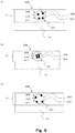
- Fig. 1 is a schematic diagram of an example of an image forming device using an image forming method in the present invention, which is an image forming device according to EXAMPLE 1 described later.
- Fig. 1 is a cross-sectional view (schematic diagram) of a printer using electrophotography as a type of an image forming device, which is a cross-sectional view along the direction of transportation of a sheet.
- the printer using electrophotography is also referred to simply as the "printer”.
- Fig. 1 is a schematic diagram (cross-sectional view) of the image forming device according to EXAMPLE 1.
- Fig. 2 is a schematic diagram (cross-sectional view) of a fixing unit according to EXAMPLE 1.
- the Y, M, C, and K in reference numerals respectively mean that the members denoted by the reference numerals are for yellow, magenta, cyan, and black colors. In the following description, the Y, M, C, and K in the reference numerals may also be omitted.
- An image forming device 100 has photosensitive drums (electrophotographic photoreceptors) 20 each as an image carrier.
- photosensitive drums electrostatic photoreceptors
- charging units primary chargers
- developing unit developing unit
- transfer unit intermediate transfer belt
- cleaning unit cleaning unit
- a recording medium 16 is supplied with appropriate timing to the respective abutting portions (transfer nip portions) of the transfer unit and the photosensitive drums 20.
- each of the photosensitive drums 20 (20Y, 20M, 20C, and 20K) is 84 mm.
- Each of the photosensitive drums 20 is driven to rotate at a peripheral speed (process speed) of 750 mm/second in the direction shown by the arrow A in Fig. 1 .
- each of the photosensitive drums 20 has a surface uniformly charged by the charging units 30 in the process of rotating.
- electrostatic latent images of individual colors each corresponding to an image exposure pattern are formed on the respective surfaces of the photosensitive drums 20 (electrostatic latent image forming step).
- the developing unit has a recording liquid including negatively charged (nega-charged) toner particles and an energy-curable liquid (carrier liquid) and transports the recording liquid carried by a development sleeve to the photosensitive drums 20.
- a development sleeve to transports the recording liquid carried by a development sleeve to the photosensitive drums 20.
- the developing unit uses development electric fields formed by the voltage (development bias) applied to the development sleeve and the surface potentials of the photosensitive drums 20, the developing unit allows the toner particles in the recording liquid to be attached to the electrostatic latent image on each of the photosensitive drums 20 and thus visualizes the electrostatic latent image as a toner image (developing step).
- the toner images are primarily transferred onto the intermediate transfer belt 70 at abutting portions 60 between the photosensitive drums 20 and primary transfer rollers 61.
- the recording medium 16 is carried by a transfer belt 80 and supplied with appropriate timing to the abutting portions of the intermediate transfer belt 70 and a secondary transfer outer roller 81.
- a secondary transfer inner roller 86 faces the secondary transfer outer roller 81 with the intermediate transfer belt 70 (and the recording medium 16) being interposed therebetween.
- the toner images are secondarily transferred from the intermediate transfer belt 70 onto the recording medium 16.
- the recording medium 16 carrying the recording liquid 15 including the unfixed toner images and the energy-curable liquid is transported by the transfer belt 80 to an irradiation position in an irradiating unit 11 serving as the fixing unit.
- the energy-curable liquid is cured to become a cured resin.
- the unfixed toner images are fixed onto the recording medium 16 (fixing step) .
- the fixing step fixes the toner images onto the recording medium without applying a pressure thereto. Then, the recording medium 16 is discharged to the outside of the image forming device.
- the pretreatment unit need not be used depending on the curing property of the energy-curable liquid.
- heating is not performed in the fixing step.
- the temperature in the fixing step is preferably not more than a glass transition temperature (Tg) in terms of preventing the deformation of the toner particle.
- Tg glass transition temperature
- the temperature in the fixing step is preferably 23 to 70°C.
- the energy-curable liquid is a UV-curable liquid and the foregoing fixing step is the step of fixing the toner images onto the recording medium without applying a pressure thereto, by irradiating the energy-curable liquid with UV light to cure the energy-curable liquid.
- the untransferred toner particle and energy-curable liquid that have not been transferred onto the intermediate transfer belt 70 and have remained on each of the photosensitive drums 20 are removed by a cleaning unit.
- Each of the photosensitive drums 20 having a surface from which the untransferred toner particle and energy-curable liquid have been removed is subjected to the formation of the next image.
- Fig. 1 is an outline view using a 4-station image forming system as an example.
- the present invention can correspond also to a 1-station image forming system or a multi-color image forming system.
- the recording liquid includes the toner particles and the energy-curable liquid (carrier liquid).
- Fig. 3 is a cross-sectional view before fixation after the toner particle (toner image formed of the toner particle) and the energy-curable liquid were transferred onto the recording medium.
- a toner particle 301 includes colorant particles 303 which produce a color.
- the toner particle 301 also contains a binder resin (toner resin) 305 for binding the colorant particles 303.
- the toner particle 301 may also contain another material such as a charge control agent not shown in addition to the binder resin 305 and the colorant particles 303.
- a coacervation method may be cited in which, while the colorant particles are dispersed and monomers for the binder resin are gradually polymerized to form the toner particle, the colorant particles are caused to be included in the toner particle.
- a method such as a grinding method in which the binder resin or the like is melted and the colorant particles are caused to be included in the binder resin can also be used.
- Kneaded Material 1 10 parts by mass of a pigment (Carbon Black MA-7 available from Mitsubishi Chemical Corporation), 10 parts by mass of the pigment dispersant, and 80 parts by mass of a solvent (tetrahydrofuran, THF) were mixed together and kneaded in a paint shaker using steel beads having a diameter of 5 mm for 1 hour to obtain Kneaded Material 1.
- a pigment Carbon Black MA-7 available from Mitsubishi Chemical Corporation
- a solvent tetrahydrofuran, THF
- To Pigment Dispersion Liquid 1 (100 parts by mass) obtained above, 200 parts by mass of dodecyl vinyl ether (DDVE) was added in small amounts, while high-speed stirring (at a rotation speed of 25000 rpm) was performed using a homogenizer (Ultra Turrax T50 available from IKA Japan K. K.), so that Solution Mixture 1 was obtained.
- DDVE dodecyl vinyl ether
- a binder resin was in a phase-separated state.
- Solution Mixture 1 was moved into an eggplant flask. From Solution Mixture 1, THF was completely distilled away at 50°C, while ultrasonic dispersion was performed, so that UV-curable liquid Toner Particle Dispersion 1 containing the toner particle in a UV-curable insulating liquid was obtained.
- Toner Particle Dispersion 1 (10 parts by mass) obtained was subjected to centrifugal separation treatment.
- the supernatant solution was removed by decantation, and new DDVE having the same mass as that of the removed supernatant solution was added to the residue, which was dispersed again.
- the resultant mixture was subjected to re-dispersion and 0.10 parts by mass of Lecinol S-10 (hydrogenated lecithin available from Nikko Chemicals Co., Ltd.), 10 parts by mass of dodecyl vinyl ether as a polymerizable liquid monomer, 80 parts by mass of cyclohexanedimethanol divinyl ether, 0.30 parts by mass of a photopolymerization initiator given by Formula (3) shown below, and 1 part by mass of KAYAKURE-DETX-S (available from Nippon Kayaku Co., Ltd.) were added to the mixture to obtain UV-curable Liquid Developer 1.
- the time required for the production was not longer than 12 hours.
- binder resin used for the toner particle examples include a polyester resin, an epoxy-based resin, a styrene acrylic resin, and the like.
- the colorant particles used for the toner particle a typical organic or inorganic pigment can be used.
- a dispersant or a synergist can also be used in the production process.
- the content of the colorant in the toner particle is preferably not less than 5 parts by mass and not more than 100 parts by mass based on 100 parts by mass of the binder resin.
- carbon black may be cited.
- a pigment which produces a blue or cyan color the following may be cited: C.I. Pigment Blue 2, 3, 15:2, 15:3, 15:4, 16, or 17; C.I. Vat Blue 6; C.I. Acid Blue 45; or a copper phthalocyanine pigment having a phthalocyanine skeleton and 1 to 5 phthalimide methyl groups as substituents.
- the toner particle includes a pigment dispersant.
- a dispersion aid a synergist in accordance with each of the pigments can also be used.
- a preferred content of each of the pigment dispersant and the pigment dispersion aid is 0.01 to 50 mass% in the toner particle.
- the pigment dispersant a known pigment dispersant can be used.
- the dispersant examples include a hydroxyl-group-containing carboxylic acid ester, a salt of a long-chain polyaminoamide and a high-molecular-weight acid ester, a salt of a high-molecular-weight polycarboxylic acid, a high-molecular-weight unsaturated acid ester, a high-molecular-weight copolymer, a modified polyacrylate, an aliphatic multivalent carboxylic acid, a formalin condensate of a naphthalene sulfonic acid, a polyoxyethylene alkyl phosphate, a pigment derivative, and the like.
- the dispersant also include a commercially available polymer dispersant such as a Solsperse series available from Lubrizol Japan Limited.
- an energy-curable liquid 302 contains a charge control agent which causes the surface of the toner particle to have charges, a photopolymerization initiator which generates an acid when irradiated with UV light, and monomers which are bound to each other by the acid.
- a charge control agent which causes the surface of the toner particle to have charges
- a photopolymerization initiator which generates an acid when irradiated with UV light
- monomers which are bound to each other by the acid is preferably a vinyl ether compound which is polymerized through a cationic polymerization reaction.
- the energy-curable liquid 302 may also contain a sensitizer in addition to the photopolymerization initiator. To suppress the degradation of a keeping quality due to photopolymerization, the energy-curable liquid 302 preferably contains not less than 10 ppm and not more than 5000 ppm of a cationic polymerization inhibitor. Besides, the energy-curable liquid 302 may also contain a charge control adjuvant, another additive, or the like.
- the monomers (cationic polymerizable monomers/UV curing agent) contained in the energy-curable liquid 302 are a mixture of a monofunctional monomer having one vinyl ether group (compound shown by Formula (1) below) and a bifunctional monomer having two vinyl ether groups (compound shown by Formula (2) below).
- the photopolymerization initiator contained in the energy-curable liquid 302 is a compound shown by Formula (3) below.
- the content of the photopolymerization initiator is 0.3 mass% based on the total mass of the foregoing monomers (cationic polymerizable monomers/UV curing agent) .
- the photopolymerization initiator given by the following Formula (6) is used preferably.
- R 3 and R 4 are bound to each other to form a ring structure, x represents an integer of 1 to 8, and y represents an integer of 3 to 17.
- Examples of the foregoing ring structure include a 5-membered ring or a 6-membered ring.
- the specific examples thereof include a succinimide structure, a phthalimide structure, a norbornene dicarboximide structure, a naphthalene dicarboximide structure, a cyclohexane dicarboximide structure, an epoxycyclohexene dicarboximide structure, and the like.
- Such a ring structure may also have, as a substituent group, an alkyl group with 1 to 4 carbons, an alkyloxy group with 1 to 4 carbons, an alkylthio group with 1 to 4 carbons, an aryl group with 6 to 10 carbons, an aryloxy group with 6 to 10 carbons, an arylthio group with 6 to 10 carbons, or the like.
- a straight-chain alkyl group (RF1) in which a hydrogen atom is substituted with a fluorine atom, a branched-chain alkyl group (RF2) in which a hydrogen atom is substituted with a fluorine atom, a cycloalkyl group (RF3) in which a hydrogen atom is substituted with a fluorine atom, or an aryl group (RF4) in which a hydrogen atom is substituted with a fluorine atom may be cited.
- the content of the photopolymerization initiator is not particularly limited, but is preferably 0.01 to 5 parts by mass on the basis of 100 parts by mass of the cationic polymerizable monomer (preferably a vinyl ether compound) .
- the foregoing cationic polymerizable monomer is at least one compound selected from the group consisting of dodecyl vinyl ether, dipropylene glycol divinyl ether, dicyclopentadiene vinyl ether, cyclohexane dimethanol divinyl ether, tricyclodecane vinyl ether, trimethylolpropane trivinyl ether, 2-ethyl-1,3-hexanediol divinyl ether, 2,4-diethyl-1,5-pentanediol divinyl ether, 2-buthyl-2-ethyl-1,3-propanediol divinyl ether, neopentyl glycol divinyl ether, pentaerythritol tetra vinyl ether, and 1,2-decanediol divinyl ether.
- dodecyl vinyl ether dipropylene glycol divinyl ether, dicyclopentadiene vinyl ether,
- Fig. 4 is a conceptual cross-sectional view after fixation after the energy-curable liquid was irradiated with UV light.
- the energy-curable liquid 302 When the energy-curable liquid 302 is irradiated with a predetermined amount of UV light at a wavelength of, e.g., 365 to 410 nm, the energy-curable liquid 302 undergoes a polymerization reaction to be cured.
- the energy-curable liquid is a UV-curable liquid
- a unit having, e.g., a mercury lamp, a UV laser, a UV-LED, or the like can be used.
- the cumulative irradiation energy of the UV light is preferably not less than 0.1 mJ/cm 2 and not more than 1000 mJ/cm 2 .
- an LED Light Emitting Diode which emits UV light is used as a light source.
- the first law of photochemistry i.e., that "of the projected light quantity, only the absorbed light brings about a photochemical change”. That is, in the UV curing, the coincidence between the absorption wavelength of the photopolymerization initiator and the light emission wavelength of the UV irradiating unit is important.
- the LEDs include LED light sources which have peak illuminances at wavelengths of 365 ⁇ 5 nm, 385 ⁇ 5 nm, 405 ⁇ 5 nm, and the like. Accordingly, the absorption of the photopolymerization initiator preferably occurs in such wavelength regions.
- the LEDs which emit UV light may be arranged in one row or a plurality of rows in in a long side direction.
- a maximum illuminance at a position on the surface of a transported object at a position immediately under the LED is referred to as a peak illuminance.
- an irradiation energy received per unit area is the total quantity of photons reaching the surface "CUMULATIVE LIGHT QUANTITY (mJ/cm 2 )", which results from the multiplication of a cumulative illuminance (mW/cm 2 ) at each of the wavelengths of the UV irradiating unit described above by an irradiation time (s) ((mW/cm 2 ) x (s)).
- the irradiation time is shorter. That is, when the transportation speed increases and the irradiation time decreases, the "CUMULATIVE LIGHT QUANTITY (mJ/cm 2 )" which determines the curing property decreases so that the energy-curable liquid is less likely to be cured.
- the UV curing resin cationic polymerizable monomer
- the toner particle 301 is not cured by UV light.
- the toner particle 301 is included in the cured resin serving as the cured material of the energy-curable liquid.
- experiment conditions can appropriately cover a recording liquid viscosity as high as about 0.5 to 50 mPa ⁇ s and a resistance as high as about 1 ⁇ 10 10 to 1 ⁇ 10 13 ⁇ cm.
- the CIE L*a*b* (CIE LAB) used this time is a substantially complete color space and is designed by the International Commission on Illumination (CIE).
- the CIE LAB can describe substantially all the colors that can be seen by human eyes and is intended to be able to be used as a standard for a device independent model.
- a* negative values indicate colors closer to green, while positive values indicate colors closer to magenta
- b* yellow and blue
- negative values indicate colors closer to blue, while positive values indicate colors closer to yellow.
- Each of the coordinates has an asterisk (*) to be clearly distinguished from that of the Hunter Lab described later.
- a GretagMacbeth spectrophotometer available from X-Rite Inc. was used.
- the volume-average particle diameter of the toner particles is not less than 0.5 ⁇ m and not more than 1 ⁇ m. In the present embodiment, toner particles having a volume-average particle diameter of 1 ⁇ m were used.
- the ratio (PB ratio or P:B) between the pigment (P) and the binder resin (B) as a mass ratio in each of the toner particles is preferably in the range of 1:1 to 1:8.
- the toner particle having a PB ratio of 1:4 was used.
- the volume-average particle diameter of the pigments is not less than 0.05 ⁇ m and not more than 0.400 ⁇ m.
- the pigments having a volume-average particle diameter of 0.075 nm were used.
- the ratio (TD ratio or T/D ⁇ 100 [%]) between the toner particle (T) and the carrier liquid (energy-curable liquid) (D) is preferably not less than 20% and not more than 80% on a mass scale. In the present embodiment, the toner particle and the carrier liquid having a T/D ratio of 55% were used.
- the refractive index of the carrier liquid is not less than 1.40 and not more than 1.65.
- the carrier liquid having a refractive index of 1.51 was used.
- the refractive index between the toner particle and the cured resin is not less than 1.45 and not more than 1.70.
- the toner particle and the cured resin having a refractive index of 1.56 therebetween was used.
- the film thickness of the cured resin including the toner image on the surface of the recording medium (media) is not less than 0.5 ⁇ m and not more than 4 ⁇ m in the case where only one color is used.
- the cured resin having a film thickness of 1.5 ⁇ m was used.
- the wavelength of the UV light used for curing was set to 385 ⁇ 5 nm.
- the energy at the surface of the recording medium (media) was set to 1400 mW/cm 2 .
- the distance between the recording medium and the UV-LED unit was set to 10 mm.
- the transportation speed of the recording medium was set to 1000 mm/s .
- a coated paper sheet (OKTOP157) was used as the recording medium.
- the irradiation width of a UV fixer at the surface of the recording medium was set to about 30 mm.
- the cumulative energy of UV irradiation was set to 100 mJ/cm 2 . It is assumed that, in the experiment in the present embodiment, there was no pressure-heating fixation (no pressure/heat application).
- the toner particle has a shape (average circularity) of not less than 0.70 and not more than 0.99. In the present embodiment, the toner particle having an average circularity of 0.98 was used.
- the carrier liquid (energy-curable liquid) was made to contain 100 ppm of a cationic polymerization inhibitor based on the total mass of the carrier liquid (energy-curable liquid). The viscosity of the recording liquid was adjusted to 5 mPa ⁇ s and the resistance thereof was adjusted to 1 ⁇ 10 11 ⁇ m.
- the average circularity of the toner particle included in the cured resin is not less than 0.70 and not more than 0.99.
- the average circularity is preferably not less than 0.80 and not more than 0.99 and more preferably not less than 0.90 and not more than 0.99.
- the average circularity can be achieved by, e.g., giving an energy to the energy-curable liquid without applying a pressure when the energy curing liquid is cured and a toner image is fixed onto the recording medium.
- a cross section having a largest diameter corresponding to Volume-Average Particle Diameter of Toner Particle ⁇ 10% is selected and subjected to measurement.
- the cross sections of 100 toner particles are subjected to measurement and the arithmetic average value of the circularities thereof is used.
- a transparent or opaque resin film which is used for soft packaging and which does not absorb a liquid can also be used instead of a typical paper sheet.
- a resin for the resin film include polyethylene terephthalate, polyester, polyimide, polypropylene, polystyrene, polycarbonate, and the like.
- Figs. 5(a) to 5(c) are conceptual cross-sectional views showing the dispersibility (dispersed state) of the pigments (colorant particles/color material) 303 included in the toner particle 301.
- the toner particle 301 includes the colorant particles 303.
- the distribution of the colorant particles 303 differs, the lightness and the chroma vary under the influence of the reflection and scattering of light.
- a chroma of less than 40 was evaluated as C.
- a chroma of not less than 40 and less than 60 was evaluated as B.
- a chroma of not less than 60 was evaluated as A.
- a lightness of less than 30 was evaluated as C.
- a lightness of not less than 30 and less than 35 was evaluated as B.
- a lightness of not less than 35 was evaluated as A.
- the toner particles in EXAMPLES 1-1 to 1-3 were produced in accordance with the "method of producing a developer in EXAMPLE 1" described above.
- the content of the pigment dispersant (hydroxyl-group-containing carboxylic acid ester) in the toner particle was set to 15 mass% on the basis of the total mass of the toner particle in EXAMPLE 1-1, to 5 mass% on the basis of the total mass of the toner particle in EXAMPLE 1-2, and to 30 mass% on the basis of the total mass of the toner particle in EXAMPLE 1-3.
- the pigment dispersant functions to surround each one of the individual pigments and reduce the likeliness of the pigments to come closer to each other.
- the dispersant was smaller in amount than in EXAMPLE 1-1. Accordingly, the pigments more densely concentrated at the center of the toner particle than in EXAMPLE 1-1.
- UV light cures substantially only the energy-curable liquid, the influence exerted by the UV light on the toner particle is small. Consequently, when the toner particle 301 is exposed from the cured resin 17 (exposed portion 320), roughness is produced in the surface of an image.
- a cross section of the image on the surface of a paper sheet as the recording medium was observed.
- the following is a specific procedure for obtaining a cross-sectional image.
- a cross section of the image on the surface of the paper sheet as the recording medium was observed and the amount of exposure was measured.
- the following is a specific procedure for obtaining a cross-sectional image.
- an output media is wrapped with an epoxy cured resin to be fixed and cut using a microtome to expose the cross section.
- the cut sample having a thickness of about 5 mm is placed on a double-face conductive tape and imaged using the scanning electron microscope (SEM) JSM-7500 F. In this manner, the state of the cross section of the image can be observed.
- the contour of the toner particle is described. Then, the interface of the surface of the image is plotted and a moving average line is calculated from the plots. Then, the area (exposed area) of the portion of the toner particle which is located outside the moving average line described above is calculated. When the area (exposed area) outside the moving average line was not less than 10% of the area of the toner particle, it was determined that the toner particle was exposed from the surface of the cured resin. Note that, as the toner to be subjected to the measurement, 100 toner particles present on the interface of the surface of the image were selected and the arithmetic average value of the exposed area was used.
- the recording medium was an OKTOP coated paper sheet and the surface roughness (ten-point average roughness) Rz of the recording medium was 2 ⁇ m.
- Rz was about 2 ⁇ m, which was substantially the same as the surface roughness of the recording medium. In short, the gloss was about 35 degrees.
- the carrier liquid is preferable to cause curing without vaporizing the carrier liquid. That is, it is desirable to minimize the amount of the carrier liquid vaporized into the atmosphere or reduce the time from the formation of the toner image to the curing with the UV light.
- the carrier liquid is likely to be vaporized so that the toner particle tends to be exposed.
- a toner particle (and the binder resin thereof) does not exist and pigments are dispersed directly in a cured resin such as a carrier, as shown in Fig. 7(b) .
- Table 3 shows the results of evaluating a chromogenic property in such a case.
- COMPARATIVE EXAMPLE 2 in Fig. 7(b) was obtained by applying the carrier liquid, the pigment dispersant, and Pigment Blue 15:3 as the pigments each used in EXAMPLE 1 using a select-coater (film thickness of 1.5 ⁇ m: OSP-1.5 #0.7 PO. 08H4S 1.5 available from MATSUO SANGYO CO., LTD.) without using an image forming device employing electrophotography and curing the resulting coating with UV light.
- a select-coater film thickness of 1.5 ⁇ m: OSP-1.5 #0.7 PO. 08H4S 1.5 available from MATSUO SANGYO CO., LTD.
- the particle diameter of the toner particle is 1 ⁇ m
- the particle diameter of the pigment is 0.1 ⁇ m
- the total number of the pigments is 8.
- pigments are dispersed in an island-like configuration, as shown in Fig. 7(c) , four pigments (pigments 0 to 3) and pigments 4 to 7 are disposed in one toner. The distances therebetween were calculated on the basis of the pigment 0. The average value was 0.79 ⁇ m and the standard deviation was 0.47.
- EXAMPLE 1-4 by using the toner particles in which the colorant particles are included in the binder resin and locating the toner particles in an island-like configuration in the cured resin, it is possible to further increase the lightness and the chroma.
- Fig. 8(a) shows the case where the toner was not deformed.
- Fig. 8(b) shows the case where the toner was deformed by heat or pressure.
- COMPARATIVE EXAMPLE 3 in Fig. 8(b) is an example in which the recorded material obtained in EXAMPLE 1-1 was fed through a rigid-body heat roller and a pressure roller at a temperature of 150°C, under a total pressure g of 100 N, at a longitudinal width of 325 mm, and at a nip width of 8 mm.
- the changed shape was evaluated using an average circularity as an index.
- the result of the experiment is shown in Table 4. Note that a method of measuring the average circularity is as described above.
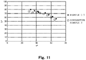
- Fig. 11 shows the experiment data of the lightness and the chroma. Each of the points in Fig. 11 shows the result of measurement obtained under the following conditions.
- the state where the colorant particles are dispersed in an island configuration in the toner particle, while the shape of the toner particle is maintained, and the toner particle is included in the cured resin and is not exposed to the outside of the cured resin has the effect of further increasing the lightness and the chroma.
- the values in the present example are only illustrative and are preferably optimized under each of the set conditions.
- Figs. 9(a) to 9(c) are cross sections when the particle diameters of the toner particles were changed in the state where the quantity of the colorant particles per unit area was equal. 312 shows the distances between the respective wall surfaces of the toner particles. Table 5 shows the result of evaluating the lightness and the chroma in the same manner as in EXAMPLE 1.
- an image was output using electrophotography.
- the method of producing the developer was as described above. Since the toner particle dispersant contributes to particle formation, by varying the content of the toner particle dispersant, the diameter and circularity of the particle can be controlled. Examples of a commercially available product of the foregoing toner particle dispersant include AJISPER PB-817 (available from AJINOMOTO Fine-Techno Co., Inc.), Solsperse 11200, 13940, 17000 and 18000 (available from Lubrizol Japan Limited), and the like.
- the toner particles were irradiated with light using a particle shape/diameter analyzing device FPIA-3000 available from Sysmex Corporation. From the detected value, a cross-sectional area was measured and the volume-average particle diameters of 500 toner particles were calculated.
- the volume-average particle diameter of the toner particles which was not less than 1 ⁇ m was evaluated to be "Large”.
- the volume-average particle diameter of the toner particles which was not less than 0.5 ⁇ m and less than 1 ⁇ m was evaluated to be "Intermediate”.
- the volume-average particle diameter of the toner particles which was less than 0.5 ⁇ m was evaluated to be "Small”.
- the cross-sectional images of the toner particles were obtained.
- the areas occupied by the pigment particles relative to the cross-sectional areas were measured and the quantities of the pigments were calculated.
- output media is wrapped with an epoxy cured resin to be fixed and cut using a microtome to expose the cross section.
- the cut sample having a thickness of about 5 mm is placed on a double-face conductive tape and imaged using the scanning electron microscope (SEM) JSM-7500 F. What is important for imaging is to give the contrast between the developer and the ambient carrier using an acceleration voltage (e.g., 15 kv).
- an acceleration voltage e.g. 15 kv.
- the area and equivalent circle diameter of one particle and the center coordinates of the equivalent circle diameter of one particle in the window of the imaging software are calculated.
- the center coordinates are similarly calculated.
- the individual center coordinates are connected (center line).
- the outer peripheral points of the equivalent circuit diameter intersecting the center line are plotted.
- the distance between the plots for the adjacent particles is assumed to be the distance between the wall surfaces.
- the distance between the walls surfaces described above is measured in the window in the software.
- the distances between the wall surfaces of 100 adjacent pairs of the particles are measured and the arithmetic average value thereof is used.
- the average distance between the wall surfaces which was less than 75 nm was evaluated to be "Small”.
- the average distance between the wall surfaces which was not less than 75 nm and less than 125 nm was evaluated to be "Intermediate”.
- the average distance between the wall surfaces which was not less than 125 nm and less than 150 nm was evaluated to be "Large”.
- the average distance between the wall surfaces of the toner particles has an appropriate value.
- Fig. 12 shows the result of conducting, in EXAMPLES 2-1, 2-2 and COMPARATIVE EXAMPLE 4, the same study as conducted in EXAMPLE 1. It can be seen that, as the average distance between the wall surfaces of the toner particles increases, the chroma decreases. Thus, the average distance between the wall surfaces of the particles is preferably less than 125 nm. With regard to the minimum value of the distance between the wall surfaces of the toner particles, the mechanical barrier of the surface of the toner particle included in the energy-curable liquid is mostly about not less than 75 nm on average (The average size of the charge control agent attached to the surface of the toner particle is mostly about 75 nm.). Accordingly, the average distance between the wall surfaces of the adjacent toner particles is preferably not less than 75 nm. The average distance between the wall surfaces of the adjacent toner particles is not less than 75 nm and less than 125 nm.
- the distance between the wall surfaces can be controlled in two types of directions. For example, by increasing the amount of the toner relative to the carrier, the bulk density is increased to reduce the distance between the wall surfaces. Conversely, by reducing the amount of the toner relative to the carrier liquid, the distance between the wall surfaces can be increased. For example, when the amount of the toner and the carrier is D and the amount of the toner is T (mass%), the distance between the wall surfaces at a 75% TD ratio is 10 nm and the distance between the wall surfaces at a 66% TD ratio is 200 nm.
- Fig. 13 shows a spectral sensitivity (spectral reflectivity) at each of the distances.
- the average distance between the wall surfaces which was 170 nm was evaluated to be "Very Large”.
- the average distance between the wall surfaces which was 140 nm was evaluated to be "Large”.
- the average distance between the wall surfaces which was 100 nm was evaluated to be “Intermediate”.
- the average distance between the wall surfaces which was 40 nm was evaluated to be "Small”.
- the quantity of the colorant particles included in each one of the toner particles has decreased, by increasing the film thickness such that the toner particles are present in multiple layers, appropriate color production can be ensured.
- the presence of the toner particles in the multiple layers is disadvantageous in that the amounts of the consumed binder resin and the consumed cured resin (curable liquid) increase.
- EXAMPLES 2-4 to 2-6 recorded materials were produced in the same manner as in EXAMPLE 1-1 except that 20 parts by mass, 25 parts by mass, and 10 parts by mass of the pigments were used in EXAMPLES 2-4, 2-5, and 2-6, respectively, on the basis of 100 parts by mass of the binder resin used in EXAMPLE 1.
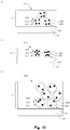
- Table 6 shows the result of the experiment in the cases where the quantity of the pigments per toner particle was large ( Fig. 10(b) ) and where the quantity of the pigments per toner particle was small ( Fig. 10(c) ).
- EXAMPLE 2-4 EXAMPLE 2-5 EXAMPLE 2-6
- Figure 10(a) 10(b) 10(c) Volume-Average Particle Diameter of Toner Particles Intermediate Intermediate Intermediate Quantity of Pigments per Toner Particle Intermediate Large Small Average Distance between Wall Surfaces of Adjacent Toner Particles Intermediate Intermediate Intermediate Film Thickness Intermediate Small Large Chromogenic Property Chroma
- the film thickness is varied in accordance with the quantity of the pigments included in one toner particle, by setting the average distance between the respective wall surfaces of the toner particles to a value in a predetermined range, the lightness and the chroma can be maintained at a high level.
Landscapes
- Physics & Mathematics (AREA)
- General Physics & Mathematics (AREA)
- Chemical & Material Sciences (AREA)
- Chemical Kinetics & Catalysis (AREA)
- Spectroscopy & Molecular Physics (AREA)
- Liquid Developers In Electrophotography (AREA)
- Fixing For Electrophotography (AREA)
- Developing Agents For Electrophotography (AREA)
Applications Claiming Priority (2)
| Application Number | Priority Date | Filing Date | Title |
|---|---|---|---|
| JP2015107667 | 2015-05-27 | ||
| PCT/JP2016/065687 WO2016190410A1 (ja) | 2015-05-27 | 2016-05-27 | 記録物及び画像形成方法 |
Publications (3)
| Publication Number | Publication Date |
|---|---|
| EP3306401A1 EP3306401A1 (en) | 2018-04-11 |
| EP3306401A4 EP3306401A4 (en) | 2018-12-05 |
| EP3306401B1 true EP3306401B1 (en) | 2020-11-11 |
Family
ID=57393488
Family Applications (1)
| Application Number | Title | Priority Date | Filing Date |
|---|---|---|---|
| EP16800114.7A Active EP3306401B1 (en) | 2015-05-27 | 2016-05-27 | Recorded matter and image forming method |
Country Status (5)
| Country | Link |
|---|---|
| US (1) | US10372053B2 (https=) |
| EP (1) | EP3306401B1 (https=) |
| JP (1) | JP6762760B2 (https=) |
| CN (1) | CN107710077B (https=) |
| WO (1) | WO2016190410A1 (https=) |
Families Citing this family (4)
| Publication number | Priority date | Publication date | Assignee | Title |
|---|---|---|---|---|
| JP6501615B2 (ja) | 2015-05-27 | 2019-04-17 | キヤノン株式会社 | 液体現像剤及び該液体現像剤の製造方法 |
| US10545424B2 (en) | 2017-09-28 | 2020-01-28 | Canon Kabushiki Kaisha | Liquid developer and method of producing liquid developer |
| JP7140609B2 (ja) | 2017-09-28 | 2022-09-21 | キヤノン株式会社 | 液体現像剤及び該液体現像剤の製造方法 |
| US10423084B2 (en) | 2017-11-20 | 2019-09-24 | Canon Kabushiki Kaisha | Method for producing liquid developer |
Family Cites Families (28)
| Publication number | Priority date | Publication date | Assignee | Title |
|---|---|---|---|---|
| JPH0623867B2 (ja) | 1988-12-09 | 1994-03-30 | キヤノン株式会社 | カラー画像形成方法および静電潜像現像用顕画粒子 |
| US5364726A (en) * | 1990-03-30 | 1994-11-15 | Xerox Corporation | Liquid developers having curable liquid vehicles |
| JP3442406B2 (ja) | 1990-03-30 | 2003-09-02 | ゼロックス・コーポレーション | 硬化性液体ベヒクルを有する液体現像剤 |
| JP3189185B2 (ja) | 1991-02-13 | 2001-07-16 | ゼロックス コーポレーション | 硬化性液体ベヒクルを含有する液体現像剤 |
| US5620783A (en) | 1992-03-30 | 1997-04-15 | Canon Kabushiki Kaisha | Transfer paper for outputting color images and method of forming color images by using same |
| JP4815074B2 (ja) | 2001-08-08 | 2011-11-16 | 株式会社リコー | 電子写真液体現像剤及び画像形成方法 |
| DE102004009987B3 (de) * | 2004-03-01 | 2005-10-20 | Oce Printing Systems Gmbh | Verfahren zum Bedrucken eines Aufzeichnungsträgers |
| JP2006249332A (ja) * | 2005-03-11 | 2006-09-21 | Seiko Epson Corp | インク |
| WO2006126566A1 (ja) | 2005-05-26 | 2006-11-30 | Sakata Inx Corp. | 液体現像剤およびその製造方法 |
| US8399170B2 (en) | 2005-06-27 | 2013-03-19 | Sakata Inx Corp. | Process for production of liquid developer, and liquid developer produced by the process |
| JP5175548B2 (ja) | 2005-06-27 | 2013-04-03 | サカタインクス株式会社 | 液体現像剤の製造方法およびその製造方法により得られた液体現像剤 |
| JP2007192948A (ja) * | 2006-01-17 | 2007-08-02 | Seiko Epson Corp | 液体現像剤 |
| JP5090338B2 (ja) | 2006-03-22 | 2012-12-05 | サカタインクス株式会社 | 液体現像剤の製造方法及びその方法によって得られる液体現像剤 |
| JP5125883B2 (ja) | 2008-03-17 | 2013-01-23 | セイコーエプソン株式会社 | 液体現像剤および画像形成方法 |
| JP5277800B2 (ja) * | 2008-09-03 | 2013-08-28 | セイコーエプソン株式会社 | 液体現像剤 |
| JP5549241B2 (ja) * | 2009-06-17 | 2014-07-16 | 株式会社リコー | 光硬化型液体現像剤、現像装置及び画像形成装置。 |
| JP5663899B2 (ja) * | 2010-03-03 | 2015-02-04 | 株式会社リコー | 光硬化型液体インク、光硬化型液体インクの製造方法、現像装置及び画像形成装置 |
| JP5636958B2 (ja) * | 2010-12-29 | 2014-12-10 | 富士ゼロックス株式会社 | 液体現像剤、現像剤カートリッジ、画像形成方法、及び画像形成装置 |
| JP2013152348A (ja) * | 2012-01-25 | 2013-08-08 | Seiko Epson Corp | 液体現像剤 |
| JP6136805B2 (ja) * | 2013-09-20 | 2017-05-31 | コニカミノルタ株式会社 | 液体現像剤および画像形成方法 |
| AU2014355607B2 (en) | 2013-11-28 | 2017-04-20 | Canon Kabushiki Kaisha | Ultraviolet-Curable Liquid Developer |
| US9891546B2 (en) | 2015-05-27 | 2018-02-13 | Canon Kabushiki Kaisha | Ultraviolet-curable liquid developer |
| US9740118B2 (en) | 2015-05-27 | 2017-08-22 | Canon Kabushiki Kaisha | Method of producing liquid developer |
| US9804539B2 (en) | 2015-05-27 | 2017-10-31 | Canon Kabushiki Kaisha | Image forming apparatus and image forming method |
| US9891547B2 (en) | 2015-05-27 | 2018-02-13 | Canon Kabushiki Kaisha | Ultraviolet-curable liquid developer |
| JP6468947B2 (ja) | 2015-05-27 | 2019-02-13 | キヤノン株式会社 | 紫外線硬化型液体現像剤及びその製造方法 |
| EP3098659A1 (en) | 2015-05-27 | 2016-11-30 | Canon Kabushiki Kaisha | Curable liquid developer and image-forming method using curable liquid developer |
| JP6504917B2 (ja) | 2015-05-27 | 2019-04-24 | キヤノン株式会社 | 硬化型液体現像剤の製造方法 |
-
2016
- 2016-05-27 WO PCT/JP2016/065687 patent/WO2016190410A1/ja not_active Ceased
- 2016-05-27 EP EP16800114.7A patent/EP3306401B1/en active Active
- 2016-05-27 JP JP2016105859A patent/JP6762760B2/ja active Active
- 2016-05-27 CN CN201680030737.5A patent/CN107710077B/zh active Active
- 2016-12-21 US US15/386,645 patent/US10372053B2/en active Active
Non-Patent Citations (1)
| Title |
|---|
| None * |
Also Published As
| Publication number | Publication date |
|---|---|
| JP6762760B2 (ja) | 2020-09-30 |
| EP3306401A4 (en) | 2018-12-05 |
| CN107710077A (zh) | 2018-02-16 |
| CN107710077B (zh) | 2021-03-30 |
| WO2016190410A1 (ja) | 2016-12-01 |
| EP3306401A1 (en) | 2018-04-11 |
| US10372053B2 (en) | 2019-08-06 |
| US20170102628A1 (en) | 2017-04-13 |
| JP2016224444A (ja) | 2016-12-28 |
Similar Documents
| Publication | Publication Date | Title |
|---|---|---|
| US9348253B2 (en) | Image-forming method | |
| EP3306401B1 (en) | Recorded matter and image forming method | |
| US9091971B2 (en) | Image-forming apparatus | |
| US20130164004A1 (en) | Image forming apparatus | |
| US20100209149A1 (en) | Image forming apparatus and image forming method | |
| JP5434790B2 (ja) | 弾性転写ベルト、及びこれを用いた画像形成装置 | |
| US8843049B2 (en) | Electrophotographic image forming method | |
| CN101042544B (zh) | 成像设备、成像方法和处理盒 | |
| CN104914685A (zh) | 电子照相感光体 | |
| JP2003295496A (ja) | 画像形成方法 | |
| JP5838625B2 (ja) | 画像形成装置 | |
| JP2014186191A (ja) | 画像形成方法 | |
| KR100413993B1 (ko) | 화상 형성 장치 및 화상 형성 장치에 사용되는 프로세스카트리지 | |
| JP6614807B2 (ja) | 画像形成装置 | |
| US6333132B1 (en) | Toner for two-component developer and color image forming apparatus | |
| JP2010032689A (ja) | 液体現像剤、および液体現像剤を用いた画像形成装置 | |
| US9031432B2 (en) | Wet-type image forming apparatus and method of setting transfer bias in wet-type image forming apparatus | |
| JP2009169262A (ja) | 液体現像剤およびその製造方法、ならびに液体現像剤を用いた画像形成装置 | |
| JP5144215B2 (ja) | 画像形成装置及び画像形成方法 | |
| US20110097658A1 (en) | Electrophotographic toner | |
| JP5418026B2 (ja) | 電子写真用シームレスベルト及びそれを用いた電子写真装置 | |
| JP2020197622A (ja) | 中間転写体、その製造方法及びそれを備えた画像形成装置 | |
| JP3894025B2 (ja) | 画像形成方法 | |
| JP2010102325A (ja) | 画像形成装置 | |
| US20190212670A1 (en) | Image forming apparatus |
Legal Events
| Date | Code | Title | Description |
|---|---|---|---|
| STAA | Information on the status of an ep patent application or granted ep patent |
Free format text: STATUS: THE INTERNATIONAL PUBLICATION HAS BEEN MADE |
|
| PUAI | Public reference made under article 153(3) epc to a published international application that has entered the european phase |
Free format text: ORIGINAL CODE: 0009012 |
|
| STAA | Information on the status of an ep patent application or granted ep patent |
Free format text: STATUS: REQUEST FOR EXAMINATION WAS MADE |
|
| 17P | Request for examination filed |
Effective date: 20180102 |
|
| AK | Designated contracting states |
Kind code of ref document: A1 Designated state(s): AL AT BE BG CH CY CZ DE DK EE ES FI FR GB GR HR HU IE IS IT LI LT LU LV MC MK MT NL NO PL PT RO RS SE SI SK SM TR |
|
| AX | Request for extension of the european patent |
Extension state: BA ME |
|
| DAV | Request for validation of the european patent (deleted) | ||
| DAX | Request for extension of the european patent (deleted) | ||
| A4 | Supplementary search report drawn up and despatched |
Effective date: 20181106 |
|
| RIC1 | Information provided on ipc code assigned before grant |
Ipc: G03G 9/08 20060101ALI20181029BHEP Ipc: G03G 9/13 20060101AFI20181029BHEP Ipc: G03G 9/135 20060101ALI20181029BHEP Ipc: G03G 9/125 20060101ALI20181029BHEP Ipc: G03G 9/10 20060101ALI20181029BHEP Ipc: G03G 9/12 20060101ALI20181029BHEP Ipc: G03G 9/087 20060101ALI20181029BHEP |
|
| STAA | Information on the status of an ep patent application or granted ep patent |
Free format text: STATUS: EXAMINATION IS IN PROGRESS |
|
| 17Q | First examination report despatched |
Effective date: 20190821 |
|
| GRAP | Despatch of communication of intention to grant a patent |
Free format text: ORIGINAL CODE: EPIDOSNIGR1 |
|
| STAA | Information on the status of an ep patent application or granted ep patent |
Free format text: STATUS: GRANT OF PATENT IS INTENDED |
|
| INTG | Intention to grant announced |
Effective date: 20200519 |
|
| GRAS | Grant fee paid |
Free format text: ORIGINAL CODE: EPIDOSNIGR3 |
|
| GRAA | (expected) grant |
Free format text: ORIGINAL CODE: 0009210 |
|
| STAA | Information on the status of an ep patent application or granted ep patent |
Free format text: STATUS: THE PATENT HAS BEEN GRANTED |
|
| AK | Designated contracting states |
Kind code of ref document: B1 Designated state(s): AL AT BE BG CH CY CZ DE DK EE ES FI FR GB GR HR HU IE IS IT LI LT LU LV MC MK MT NL NO PL PT RO RS SE SI SK SM TR |
|
| REG | Reference to a national code |
Ref country code: GB Ref legal event code: FG4D |
|
| REG | Reference to a national code |
Ref country code: CH Ref legal event code: EP |
|
| REG | Reference to a national code |
Ref country code: AT Ref legal event code: REF Ref document number: 1334072 Country of ref document: AT Kind code of ref document: T Effective date: 20201115 |
|
| REG | Reference to a national code |
Ref country code: DE Ref legal event code: R096 Ref document number: 602016047750 Country of ref document: DE |
|
| REG | Reference to a national code |
Ref country code: IE Ref legal event code: FG4D |
|
| REG | Reference to a national code |
Ref country code: NL Ref legal event code: MP Effective date: 20201111 |
|
| REG | Reference to a national code |
Ref country code: AT Ref legal event code: MK05 Ref document number: 1334072 Country of ref document: AT Kind code of ref document: T Effective date: 20201111 |
|
| PG25 | Lapsed in a contracting state [announced via postgrant information from national office to epo] |
Ref country code: NO Free format text: LAPSE BECAUSE OF FAILURE TO SUBMIT A TRANSLATION OF THE DESCRIPTION OR TO PAY THE FEE WITHIN THE PRESCRIBED TIME-LIMIT Effective date: 20210211 Ref country code: RS Free format text: LAPSE BECAUSE OF FAILURE TO SUBMIT A TRANSLATION OF THE DESCRIPTION OR TO PAY THE FEE WITHIN THE PRESCRIBED TIME-LIMIT Effective date: 20201111 Ref country code: PT Free format text: LAPSE BECAUSE OF FAILURE TO SUBMIT A TRANSLATION OF THE DESCRIPTION OR TO PAY THE FEE WITHIN THE PRESCRIBED TIME-LIMIT Effective date: 20210311 Ref country code: FI Free format text: LAPSE BECAUSE OF FAILURE TO SUBMIT A TRANSLATION OF THE DESCRIPTION OR TO PAY THE FEE WITHIN THE PRESCRIBED TIME-LIMIT Effective date: 20201111 Ref country code: GR Free format text: LAPSE BECAUSE OF FAILURE TO SUBMIT A TRANSLATION OF THE DESCRIPTION OR TO PAY THE FEE WITHIN THE PRESCRIBED TIME-LIMIT Effective date: 20210212 |
|
| PG25 | Lapsed in a contracting state [announced via postgrant information from national office to epo] |
Ref country code: BG Free format text: LAPSE BECAUSE OF FAILURE TO SUBMIT A TRANSLATION OF THE DESCRIPTION OR TO PAY THE FEE WITHIN THE PRESCRIBED TIME-LIMIT Effective date: 20210211 Ref country code: PL Free format text: LAPSE BECAUSE OF FAILURE TO SUBMIT A TRANSLATION OF THE DESCRIPTION OR TO PAY THE FEE WITHIN THE PRESCRIBED TIME-LIMIT Effective date: 20201111 Ref country code: IS Free format text: LAPSE BECAUSE OF FAILURE TO SUBMIT A TRANSLATION OF THE DESCRIPTION OR TO PAY THE FEE WITHIN THE PRESCRIBED TIME-LIMIT Effective date: 20210311 Ref country code: LV Free format text: LAPSE BECAUSE OF FAILURE TO SUBMIT A TRANSLATION OF THE DESCRIPTION OR TO PAY THE FEE WITHIN THE PRESCRIBED TIME-LIMIT Effective date: 20201111 Ref country code: AT Free format text: LAPSE BECAUSE OF FAILURE TO SUBMIT A TRANSLATION OF THE DESCRIPTION OR TO PAY THE FEE WITHIN THE PRESCRIBED TIME-LIMIT Effective date: 20201111 Ref country code: SE Free format text: LAPSE BECAUSE OF FAILURE TO SUBMIT A TRANSLATION OF THE DESCRIPTION OR TO PAY THE FEE WITHIN THE PRESCRIBED TIME-LIMIT Effective date: 20201111 |
|
| REG | Reference to a national code |
Ref country code: LT Ref legal event code: MG9D |
|
| PG25 | Lapsed in a contracting state [announced via postgrant information from national office to epo] |
Ref country code: HR Free format text: LAPSE BECAUSE OF FAILURE TO SUBMIT A TRANSLATION OF THE DESCRIPTION OR TO PAY THE FEE WITHIN THE PRESCRIBED TIME-LIMIT Effective date: 20201111 |
|
| PG25 | Lapsed in a contracting state [announced via postgrant information from national office to epo] |
Ref country code: SM Free format text: LAPSE BECAUSE OF FAILURE TO SUBMIT A TRANSLATION OF THE DESCRIPTION OR TO PAY THE FEE WITHIN THE PRESCRIBED TIME-LIMIT Effective date: 20201111 Ref country code: LT Free format text: LAPSE BECAUSE OF FAILURE TO SUBMIT A TRANSLATION OF THE DESCRIPTION OR TO PAY THE FEE WITHIN THE PRESCRIBED TIME-LIMIT Effective date: 20201111 Ref country code: EE Free format text: LAPSE BECAUSE OF FAILURE TO SUBMIT A TRANSLATION OF THE DESCRIPTION OR TO PAY THE FEE WITHIN THE PRESCRIBED TIME-LIMIT Effective date: 20201111 Ref country code: CZ Free format text: LAPSE BECAUSE OF FAILURE TO SUBMIT A TRANSLATION OF THE DESCRIPTION OR TO PAY THE FEE WITHIN THE PRESCRIBED TIME-LIMIT Effective date: 20201111 Ref country code: RO Free format text: LAPSE BECAUSE OF FAILURE TO SUBMIT A TRANSLATION OF THE DESCRIPTION OR TO PAY THE FEE WITHIN THE PRESCRIBED TIME-LIMIT Effective date: 20201111 Ref country code: SK Free format text: LAPSE BECAUSE OF FAILURE TO SUBMIT A TRANSLATION OF THE DESCRIPTION OR TO PAY THE FEE WITHIN THE PRESCRIBED TIME-LIMIT Effective date: 20201111 |
|
| REG | Reference to a national code |
Ref country code: DE Ref legal event code: R097 Ref document number: 602016047750 Country of ref document: DE |
|
| PG25 | Lapsed in a contracting state [announced via postgrant information from national office to epo] |
Ref country code: DK Free format text: LAPSE BECAUSE OF FAILURE TO SUBMIT A TRANSLATION OF THE DESCRIPTION OR TO PAY THE FEE WITHIN THE PRESCRIBED TIME-LIMIT Effective date: 20201111 |
|
| PLBE | No opposition filed within time limit |
Free format text: ORIGINAL CODE: 0009261 |
|
| STAA | Information on the status of an ep patent application or granted ep patent |
Free format text: STATUS: NO OPPOSITION FILED WITHIN TIME LIMIT |
|
| 26N | No opposition filed |
Effective date: 20210812 |
|
| PG25 | Lapsed in a contracting state [announced via postgrant information from national office to epo] |
Ref country code: IT Free format text: LAPSE BECAUSE OF FAILURE TO SUBMIT A TRANSLATION OF THE DESCRIPTION OR TO PAY THE FEE WITHIN THE PRESCRIBED TIME-LIMIT Effective date: 20201111 Ref country code: AL Free format text: LAPSE BECAUSE OF FAILURE TO SUBMIT A TRANSLATION OF THE DESCRIPTION OR TO PAY THE FEE WITHIN THE PRESCRIBED TIME-LIMIT Effective date: 20201111 Ref country code: NL Free format text: LAPSE BECAUSE OF FAILURE TO SUBMIT A TRANSLATION OF THE DESCRIPTION OR TO PAY THE FEE WITHIN THE PRESCRIBED TIME-LIMIT Effective date: 20201111 |
|
| PG25 | Lapsed in a contracting state [announced via postgrant information from national office to epo] |
Ref country code: SI Free format text: LAPSE BECAUSE OF FAILURE TO SUBMIT A TRANSLATION OF THE DESCRIPTION OR TO PAY THE FEE WITHIN THE PRESCRIBED TIME-LIMIT Effective date: 20201111 |
|
| REG | Reference to a national code |
Ref country code: CH Ref legal event code: PL |
|
| PG25 | Lapsed in a contracting state [announced via postgrant information from national office to epo] |
Ref country code: ES Free format text: LAPSE BECAUSE OF FAILURE TO SUBMIT A TRANSLATION OF THE DESCRIPTION OR TO PAY THE FEE WITHIN THE PRESCRIBED TIME-LIMIT Effective date: 20201111 Ref country code: CH Free format text: LAPSE BECAUSE OF NON-PAYMENT OF DUE FEES Effective date: 20210531 Ref country code: MC Free format text: LAPSE BECAUSE OF FAILURE TO SUBMIT A TRANSLATION OF THE DESCRIPTION OR TO PAY THE FEE WITHIN THE PRESCRIBED TIME-LIMIT Effective date: 20201111 Ref country code: LI Free format text: LAPSE BECAUSE OF NON-PAYMENT OF DUE FEES Effective date: 20210531 Ref country code: LU Free format text: LAPSE BECAUSE OF NON-PAYMENT OF DUE FEES Effective date: 20210527 |
|
| REG | Reference to a national code |
Ref country code: BE Ref legal event code: MM Effective date: 20210531 |
|
| PG25 | Lapsed in a contracting state [announced via postgrant information from national office to epo] |
Ref country code: IE Free format text: LAPSE BECAUSE OF NON-PAYMENT OF DUE FEES Effective date: 20210527 |
|
| PG25 | Lapsed in a contracting state [announced via postgrant information from national office to epo] |
Ref country code: IS Free format text: LAPSE BECAUSE OF FAILURE TO SUBMIT A TRANSLATION OF THE DESCRIPTION OR TO PAY THE FEE WITHIN THE PRESCRIBED TIME-LIMIT Effective date: 20210311 Ref country code: FR Free format text: LAPSE BECAUSE OF NON-PAYMENT OF DUE FEES Effective date: 20210531 |
|
| PG25 | Lapsed in a contracting state [announced via postgrant information from national office to epo] |
Ref country code: BE Free format text: LAPSE BECAUSE OF NON-PAYMENT OF DUE FEES Effective date: 20210531 |
|
| PG25 | Lapsed in a contracting state [announced via postgrant information from national office to epo] |
Ref country code: CY Free format text: LAPSE BECAUSE OF FAILURE TO SUBMIT A TRANSLATION OF THE DESCRIPTION OR TO PAY THE FEE WITHIN THE PRESCRIBED TIME-LIMIT Effective date: 20201111 |
|
| PG25 | Lapsed in a contracting state [announced via postgrant information from national office to epo] |
Ref country code: HU Free format text: LAPSE BECAUSE OF FAILURE TO SUBMIT A TRANSLATION OF THE DESCRIPTION OR TO PAY THE FEE WITHIN THE PRESCRIBED TIME-LIMIT; INVALID AB INITIO Effective date: 20160527 |
|
| PG25 | Lapsed in a contracting state [announced via postgrant information from national office to epo] |
Ref country code: MK Free format text: LAPSE BECAUSE OF FAILURE TO SUBMIT A TRANSLATION OF THE DESCRIPTION OR TO PAY THE FEE WITHIN THE PRESCRIBED TIME-LIMIT Effective date: 20201111 |
|
| PG25 | Lapsed in a contracting state [announced via postgrant information from national office to epo] |
Ref country code: MT Free format text: LAPSE BECAUSE OF FAILURE TO SUBMIT A TRANSLATION OF THE DESCRIPTION OR TO PAY THE FEE WITHIN THE PRESCRIBED TIME-LIMIT Effective date: 20201111 |
|
| PGFP | Annual fee paid to national office [announced via postgrant information from national office to epo] |
Ref country code: DE Payment date: 20250423 Year of fee payment: 10 |
|
| PGFP | Annual fee paid to national office [announced via postgrant information from national office to epo] |
Ref country code: GB Payment date: 20250423 Year of fee payment: 10 |
|
| PG25 | Lapsed in a contracting state [announced via postgrant information from national office to epo] |
Ref country code: TR Free format text: LAPSE BECAUSE OF FAILURE TO SUBMIT A TRANSLATION OF THE DESCRIPTION OR TO PAY THE FEE WITHIN THE PRESCRIBED TIME-LIMIT Effective date: 20201111 |