EP3299552B1 - Modulares schloss - Google Patents
Modulares schloss Download PDFInfo
- Publication number
- EP3299552B1 EP3299552B1 EP17191596.0A EP17191596A EP3299552B1 EP 3299552 B1 EP3299552 B1 EP 3299552B1 EP 17191596 A EP17191596 A EP 17191596A EP 3299552 B1 EP3299552 B1 EP 3299552B1
- Authority
- EP
- European Patent Office
- Prior art keywords
- module
- lock
- modules
- slide plate
- follower
- Prior art date
- Legal status (The legal status is an assumption and is not a legal conclusion. Google has not performed a legal analysis and makes no representation as to the accuracy of the status listed.)
- Active
Links
Images


Classifications
-
- E—FIXED CONSTRUCTIONS
- E05—LOCKS; KEYS; WINDOW OR DOOR FITTINGS; SAFES
- E05B—LOCKS; ACCESSORIES THEREFOR; HANDCUFFS
- E05B63/00—Locks or fastenings with special structural characteristics
- E05B63/0056—Locks with adjustable or exchangeable lock parts
-
- E—FIXED CONSTRUCTIONS
- E05—LOCKS; KEYS; WINDOW OR DOOR FITTINGS; SAFES
- E05B—LOCKS; ACCESSORIES THEREFOR; HANDCUFFS
- E05B47/00—Operating or controlling locks or other fastening devices by electric or magnetic means
- E05B47/02—Movement of the bolt by electromagnetic means; Adaptation of locks, latches, or parts thereof, for movement of the bolt by electromagnetic means
- E05B47/026—Movement of the bolt by electromagnetic means; Adaptation of locks, latches, or parts thereof, for movement of the bolt by electromagnetic means the bolt moving rectilinearly
-
- E—FIXED CONSTRUCTIONS
- E05—LOCKS; KEYS; WINDOW OR DOOR FITTINGS; SAFES
- E05B—LOCKS; ACCESSORIES THEREFOR; HANDCUFFS
- E05B47/00—Operating or controlling locks or other fastening devices by electric or magnetic means
- E05B47/06—Controlling mechanically-operated bolts by electro-magnetically-operated detents
- E05B47/0676—Controlling mechanically-operated bolts by electro-magnetically-operated detents by disconnecting the handle
- E05B47/0684—Controlling mechanically-operated bolts by electro-magnetically-operated detents by disconnecting the handle radially
- E05B47/0688—Controlling mechanically-operated bolts by electro-magnetically-operated detents by disconnecting the handle radially with a pivotally moveable coupling element
-
- E—FIXED CONSTRUCTIONS
- E05—LOCKS; KEYS; WINDOW OR DOOR FITTINGS; SAFES
- E05B—LOCKS; ACCESSORIES THEREFOR; HANDCUFFS
- E05B59/00—Locks with latches separate from the lock-bolts or with a plurality of latches or lock-bolts
-
- E—FIXED CONSTRUCTIONS
- E05—LOCKS; KEYS; WINDOW OR DOOR FITTINGS; SAFES
- E05B—LOCKS; ACCESSORIES THEREFOR; HANDCUFFS
- E05B63/00—Locks or fastenings with special structural characteristics
- E05B63/18—Locks or fastenings with special structural characteristics with arrangements independent of the locking mechanism for retaining the bolt or latch in the retracted position
- E05B63/20—Locks or fastenings with special structural characteristics with arrangements independent of the locking mechanism for retaining the bolt or latch in the retracted position released automatically when the wing is closed
-
- E—FIXED CONSTRUCTIONS
- E05—LOCKS; KEYS; WINDOW OR DOOR FITTINGS; SAFES
- E05B—LOCKS; ACCESSORIES THEREFOR; HANDCUFFS
- E05B65/00—Locks or fastenings for special use
- E05B65/10—Locks or fastenings for special use for panic or emergency doors
- E05B65/1086—Locks with panic function, e.g. allowing opening from the inside without a ley even when locked from the outside
-
- E—FIXED CONSTRUCTIONS
- E05—LOCKS; KEYS; WINDOW OR DOOR FITTINGS; SAFES
- E05C—BOLTS OR FASTENING DEVICES FOR WINGS, SPECIALLY FOR DOORS OR WINDOWS
- E05C21/00—Arrangements or combinations of wing fastening, securing, or holding devices, not covered by a single preceding main group; Locking kits
-
- E—FIXED CONSTRUCTIONS
- E05—LOCKS; KEYS; WINDOW OR DOOR FITTINGS; SAFES
- E05C—BOLTS OR FASTENING DEVICES FOR WINGS, SPECIALLY FOR DOORS OR WINDOWS
- E05C9/00—Arrangements of simultaneously actuated bolts or other securing devices at well-separated positions on the same wing
Definitions
- the invention relates to a lock for a pivotably mounted leaf of a door or window according to the features of the preamble of claim 1.
- a lock which comprises a lock faceplate and a lock housing.
- individual extensions can be connected to the lock housing, which can include, for example, additional locking elements or drive devices. This makes it possible to individually upgrade the lock and adapt it to increased security requirements.
- a lock which comprises a locking cylinder module, a nut module and a slide plate.
- the locking cylinder module is connected to the slide plate via a connecting element.
- the object of the present invention is to provide a lock which covers a wide range of applications and can be manufactured in a simple manner.
- the lock should be as inexpensive to manufacture as possible.
- the lock base has mechanical receptacles for holding at least two different modules, each of which is designed as an assembly, and that the modules each have a module carrier which carries several module components of the module and is held on the receptacles of the lock base and that at least one of the modules is connected to the slide plate.
- the at least two modules each have a connecting element which establishes a connection between a module and the slide plate.
- the lock can be individually adapted to different conditions using the modules held in the lock base.
- a major advantage is that the installation space required for the lock does not change, as the modules are arranged within the lock housing. This makes it easy to manufacture and handle because each module has a module carrier that holds individual module components and combines them into an independent assembly, so to speak. By inserting this module carrier or connecting this module carrier to the lock base, the respective module is mechanically firmly and stably connected to the lock base. Individual modules can be selected for the configuration of the lock in order to put together a specific lock configuration. In addition, depending on the application, the lock can be equipped with more or fewer modules, depending on which functions the lock has to fulfill.
- the slide plate controls the extension of one or more locking elements and connects one locking element or several locking elements to one or more modules.
- the slide plate connects two or more modules to one another. These two or more modules are motion-coupled by the slide plate and connected to the locking element or several locking elements. This makes it possible to control complex locking processes.
- the at least two modules are motion-coupled to one another in order to control complex locking processes.
- one lock housing can be used to create either a simple key-operated lock, a self-locking panic lock with a control latch or auxiliary latch, or a motor lock.
- the slide plate extends from the locking element to a module arranged at a distance from the locking element or to several modules arranged at a distance from the locking element.
- the slide plate runs parallel to the lock cover or the lock base and is mounted so that it can be moved in a linear, translational manner in order to transfer a movement from one module to another module and/or from one module to the locking element or the locking elements.
- a pivotable mounting of the slide plate in the lock housing can also be provided.
- the lock is designed for a pivoting wing of a door or window in order to lock this wing against a frame.
- the lock housing can be used as a built-in housing It comprises a lock faceplate, a lock base and a removable lock cover.
- a locking element for example a lock bolt or a lock latch, is provided which passes through the lock faceplate and serves to lock the sash against a frame.
- the locking element is actuated by a slide plate and moved between a locked position excluded from the lock housing and an unlocked position retracted into the lock housing.
- the slide plate is coupled in terms of movement to the locking element.
- the mechanical mounts of the lock base can, for example, be designed as form-fitting mounts into which a module carrier is inserted. Alternatively or additionally, the mechanical mounts can also be designed as screw connections or snap or clip connections. Riveting to accommodate and hold a module carrier is also possible in this sense.
- a module carrier is understood to mean a component that is designed as a flat plate or as a preferably angled profile. Individual components of a module can be mechanically attached to this or movably mounted.
- the module carrier mechanically connects these individual module components of a module to one another to form an assembly.
- This assembly is preferably designed as an independent assembly or as an exchangeable assembly. In particular, it is provided that the assembly is designed as a part that can be handled independently of the other lock components.
- the lock base has mechanical mounts for holding at least three different modules or four different modules, depending on the requirements for the variety of functions of the lock.
- Such mechanical mounts can comprise a positive connection or a force-locking connection.
- the mounts can be designed as threads or as fitting holes or as recesses that can be gripped behind or as pins.
- the at least two modules each have a connection element that creates a connection between a module and the slide plate.
- the slide plate connects two of the modules or several of the modules to one another, in particular by the slide plate being connected to the connection elements of the modules or holding the connection elements of the modules.
- a connection element creates a connection between a module and another module.
- the connection element can be designed as a pin connection or as a screw connection or as a clip connection and accordingly have a pin, a screw or a clip. It is essential that the connection element creates a mechanically stable connection between a module and the slide plate or between a module and another module.
- connection element is movably mounted relative to the lock base and/or module carrier and transmits a movement from the module to the slide plate or another module or transmits a movement from the slide plate to the module.
- the at least two modules each have a module component that is movably mounted relative to the module carrier and/or relative to the lock base, preferably that the movably mounted module component is designed as a connection element or is connected to the connection element.
- a module is designed as an additional latch module, comprising an additional latch module carrier that carries an additional latch and a spring that acts on the additional latch and at least one gear element that can be actuated by the additional latch and a latch module connection element for connecting the additional latch to the slide plate and/or another module.
- a lock bolt can be controlled via the additional latch module in order to trigger a locking of the lock bolt in a self-locking lock as soon as the door is in the closed position.
- the additional latch module can have a sequence control that includes tamper protection and prevents the lock bolt from being locked out of the lock housing when the additional latch is accidentally actuated when the door is open.
- a module is designed as a nut module, comprising a nut module carrier which carries a lock nut or at least two nut parts and a pusher mandrel holder, as well as a nut connection element for connecting the nut module to the slide plate and/or another module.
- the nut module carrier can be provided with a lock nut which has at least two nut parts and in addition one or more pawls for coupling and/or uncoupling the nut parts are held on the nut parts or the nut module carrier.
- a module is designed as a coupling module, comprising a coupling module carrier which has a coupling motor, a coupling gear and a coupling module connection element for connecting the coupling module to the nut module.
- a module in order to enable convenient operation of the lock, one embodiment can provide for a module to be designed as a drive module, comprising a drive module carrier, a drive motor and a drive gear as well as a drive module connection element for connecting the drive module to the slide plate and/or to another module.
- the drive module can, for example, drive the locking elements of the lock and thus enable remote-controlled motorized unlocking and/or locking of the lock.
- a module is designed as a spring accumulator, comprising a spring module carrier, which has a spring, a spring guide and a spring module connection element for connecting the spring accumulator to the slide plate or another module.
- the spring accumulator can, for example, interact with the slide plate and/or a locking element in order to store the energy generated when the lock is opened. A self-locking lock can then be realized via the spring accumulator by the The energy contained in the spring accumulator is transferred to the locking element or the slide plate to lock the lock.
- the procedure is such that first the at least two modules are inserted into the lock base and fastened there and then a connection is created between the at least two modules and/or a locking element via one or more connecting elements and in a subsequent step the slide plate is inserted and connected to several of the connecting elements and at least one locking element.
- the lock housing can then be closed by attaching the lock cover.
- the at least two modules are designed as independent assemblies and are prefabricated before the modules are inserted into the lock base.
- prefabricating the modules it is possible to manufacture a lock in a modular manner within a short period of time.
- the modules are provided in stock as finished, independent assemblies and are inserted into the lock as a finished, tested and functional component when a lock is manufactured. In this way, it is possible to manufacture a lock within a significantly shorter period of time and with significantly increased quality and functional reliability.
- At least two different module types are prefabricated from one module and that a module to be inserted into the lock floor is selected from these different module types are selected.
- two module types with different drive forces are made from one module.
- the appropriate module is selected depending on the general conditions and requirements of the lock. For a lock that has less stringent requirements, the module with the lower drive force can then be selected. If the lock is to be used for heavier doors or in a harsh environment, a module with a higher drive force can be selected and inserted into the lock base.
- a production kit comprising at least two prefabricated modules that are designed as pre-assembled components and can be connected to the lock base. This production kit makes it easy to manufacture a corresponding lock or configure it individually without great mechanical effort.
- At least one module is prefabricated as a set of at least two different module types and that a specific module type is selected from this set before a module is inserted into the lock base. This makes it possible to provide a production kit with which A lock can be manufactured in different ways and adapted to different requirements.
- Another advantageous aspect of the lock according to the invention is the ease of maintenance and simple repair of the lock.
- the modular design makes it possible to easily repair the lock by replacing a module, without the need for complex disassembly and assembly, as is the case with a conventional lock, which consists of a large number of individual parts.
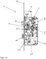
- FIGS. 1a-1c show an embodiment of the modular lock 1 according to the invention.
- the lock 1 is shown in a side view with the lock cover 14 removed.
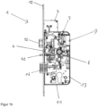
- the Fig. 1b shows the same lock in side view with the slide plate 17 removed.
- Fig. 1c the castle 1 with castle ceiling 14 is shown.
- the lock 1 has a lock housing 11.
- the lock housing 11 comprises a lock base 13, a lock cover 14 and a lock faceplate 12 arranged on the front.
- Locking elements in the form of a lock latch 15 and a lock bolt 16 are mounted in the lock housing 11.
- these locking elements are extended from the lock housing 11 and engage in a bolt receiving space that is arranged on a door frame or window frame.
- the movably mounted leaf of a door or window is locked against the door frame by the lock 1.
- the locking elements 15, 16 can be moved back into the lock housing 11 and thereby release the leaf.
- the lock housing 11 has a slide plate 17 to control or operate the locking elements 15, 16.
- the slide plate 17 has a guide slot into which a pin arranged on the locking element 16 engages. When the pin on the locking element 16 engages the slot of the slide plate 17, a movement of the slide plate 17 is converted into a movement of the locking element 16.
- the slide plate 17 and the locking element 16 are thus motion-coupled.
- a movement of the slide plate 17 in a vertical upward direction causes a movement of the locking element 16 in the locking direction; the locking element 16 moves into the lock housing 11.
- a movement of the slide plate 17 in a vertical downward direction causes a movement of the locking element in the pre-locking direction; the locking element 16 moves out of the lock housing 11.
- the slide plate 17 is used to implement a sequence control. The pre-closure of the locking element 16 is only triggered when the locking element 15 is first actuated and then released again when the additional latch 42 is actuated.
- the additional latch 42 is described in detail below.
- This sequence control serves to implement a self-locking mechanism.
- the self-locking mechanism causes the locking element 15 to automatically pre-lock, i.e. when the wing has reached its closed position on the door frame or window frame. In this position of the wing, the locking element 15 automatically extends from the lock housing 11 and engages in the locking receiving space arranged on the door frame or window frame.
- a lock nut 52 is mounted in the lock housing 11 to accommodate a door handle.
- the latch 15 and/or the bolt 16 can be unlocked via the lock nut or a door handle.
- a removable drive bolt device 2 is connected to the top of the lock housing 11.
- the drive bolt device 2 is designed as an optional module and can be removed from the lock housing 11. It serves to actuate a locking bar (not shown) of a switch lock in order to create an additional locking point for a door leaf or a window leaf.
- the lock housing 11 has several separate spaces for accommodating modules. As shown in Fig. 1b As shown, several modules are accommodated in the lock housing.
- a nut module 5 works together with a spring-loaded module 3.
- a drive module 7 is arranged in the rear area of the lock 1 in order to operate the lock 1 remotely and/or by motor.
- a latch module 4 is arranged on the faceplate side, i.e. in the front area of the lock 1, in order to control the bolt extension of the bolt 16.
- the lock housing 11 has a further installation space in the area next to the lock cylinder holder and below the drive module 16, into which an optional coupling module can be inserted. In the example shown, this installation space is empty. With the help of a coupling module, the lock 1 can be upgraded to remotely couple the lock nut with a motor and thus control the panic functions of the lock 1.
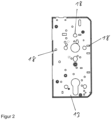
- FIG. 2 The lock base 13 is shown without any built-in parts.
- Figure 2 the receptacles 18 are visible, which are formed in the lock base and serve for the mechanical mounting of modules, such as the spring-loaded module 3 and/or the additional latch module 4 and/or the nut module 5 and/or the coupling module 6 and/or the drive module 7.
- the receptacles 18 are designed as punched-outs and/or dowel pins and/or threaded connections and are arranged in the lock base.
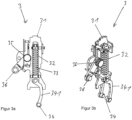
- the spring-loaded module 3 is in the Figures 3a and 3b shown.
- the Fig. 3a shows the spring-loaded module 3 in a side view.
- the Fig. 3b shows a 3D representation of the spring storage module 3.
- the spring storage module 3 comprises a spring module carrier 31.
- the spring module carrier 31 holds all components of the spring module 3.
- a compression spring 32 and a spring guide 33 are arranged on the spring module carrier 31.
- the compression spring 32 is firmly connected to the spring module carrier 31 at its upper end. Its other end is movable relative to the spring module carrier 31 and is connected to a swivel arm 341.
- the swivel arm 341 has a connection element 34 at its lower end, via which the swivel arm 341 can be connected to the nut module 5.
- the spring module also has a Torsion spring 35 which is held on the spring module carrier 31. This torsion spring 35 acts on a rotary lever, at the end of which a second connection element 36 is arranged
- the embodiments shown are a spring module 3 for a two-part nut. Accordingly, the spring storage module 3 has two springs 32 and two pivot arms 341 and two connection elements 34. In an alternative embodiment, the spring storage module 3 can also be designed as a spring storage module for a one-part nut and therefore only have one spring 32, one pivot arm 341 and one connection element 34. In addition, it is provided to design the spring storage module 3 in different spring strengths in order to adapt the spring force acting on the lock nut to the respective requirements.
- the additional trap module 4 is shown.
- the Figure 4a shows the additional trap module 4 in a side view.
- the Figure 4b shows the additional latch module 4 in a 3D view.
- the additional latch module 4 has an additional latch module carrier 41, on which the elements of the additional latch module 4 are mounted or attached.
- the additional latch module 4 is connected to the lock base 13 via the additional latch module carrier 41.
- the additional latch module 4 also has an additional latch or auxiliary latch 42 that is slidably mounted on the additional latch module carrier 41. This is acted upon by a compression spring 43 and passes through, as shown in the Figures 1a-1c shown, the lock faceplate 12.
- the additional latch module 4 has a sequence control which makes it possible to control the locking of the lock bolt 16 in a self-locking lock 1.
- the lock bolt 16 automatically closes as soon as the door or window is in the closed position.
- the additional latch module 4 is intended to prevent the lock bolt 16 from coming out of the lock housing 16 in the event of a manipulation attempt as long as the lock 1 or the leaf is not in the closed position.
- the lock latch module 4 also comprises gear elements, for example a pivoted lever 45 with a connecting element 44.
- the connecting element 44 interacts with the slide plate 17 of the lock 1 to control the bolt closure. It is intended that several types of additional latch modules are provided. For example, the logic of the sequence control or the strength of the spring 43 can be designed differently in order to be able to cover the widest possible range of applications.
- a nut module 5 is shown.
- the Fig. 5a shows the nut module in a side or top view.
- the Fig. 5b shows the nut module 5 in a three-dimensional representation.
- the nut module has a nut module carrier 51.
- Two nut parts namely the first nut part 521 and the second nut part 522, are movably mounted on the nut module carrier 51.
- a handle holder 53 is arranged in the first nut part 521 and the second nut part 522.
- two locking pawls 551, 552 are arranged on the nut module carrier 51, which are rotatably mounted on the nut module carrier 51 and each interact with a nut part 521 or 522 in order to couple or uncouple this nut part.
- this is coupled in and takes the lock nut with it when it rotates.
- the locking pawl out the corresponding nut part is uncoupled and rotates hollow when actuated without the lock nut being taken along. This makes it possible to control the handle-operated opening of the lock and different panic functions can be implemented depending on the position of the pawls.
- the nut module can be connected directly or indirectly via a transmission element to a latch module (not shown) and/or the slide plate 17 and/or the additional latch module 4 via a nut connection element 54. It is also possible to design different module types for the nut module 5.
- a nut module 5 can be provided which has only a one-piece nut or, as in the illustrated Figures 5a and 5b shown, comprises a multi-part nut.
- the coupling module 6 has a coupling module carrier 61 on which a coupling motor 62 is held.
- the coupling motor 62 actuates a coupling slide 64, which is designed as a connection element, via a coupling gear.
- the coupling module can be connected to the nut module 5 via the coupling slide 64 in order to actuate the locking pawls of the nut module 5.
- the coupling module 6 is inserted into the lock base or a receptacle 18 of the lock base 13 via the coupling module carrier 61 and held there.
- the Figures 7a and 7b show a drive module 7.
- the Fig. 7a shows a top view and the Fig. 7b shows a three-dimensional representation of the drive module 7.
- the drive module 7 has a drive module carrier 71 on which the components of the drive module 7 are held.
- the drive module carrier 71 can be used to install the drive module in the lock 1 inserted into a recess 18 in the lock base and is held there mechanically stable.
- a drive motor 52 is mounted on the drive module carrier 71 and actuates a connecting element 74 via a drive gear 73.
- the connecting element 74 is movably mounted on the drive module carrier 71 and can be moved linearly by the motor 52.
- the connecting element 74 interacts with the slide plate 17 of the lock 1 in order to actuate the locking elements, in particular the lock bolt 16 and/or the lock latch 15, i.e. to unlock or lock them.
- the drive module 7 is designed in different module types. For example, a cost-effective and/or space-saving drive module 7 can be provided, in which a smaller drive motor 52 is used. Furthermore, an additional drive module type can be provided, in which a larger drive motor 72 is used in order to achieve a higher actuation force. Depending on the requirements placed on the lock 1, the corresponding drive module 7 can be selected and inserted into the lock base 13. This makes it possible to adapt the lock 1 to a wide variety of requirements in a simple manner, without the need for a structural revision of the lock.
- the lock base 13 can be manufactured as a separate part and provided with the exceptions 18.
- the individual modules are prefabricated and are already available as stock items. It is intended that different module types can be manufactured from individual modules. which differ, for example, in terms of strength or robustness.
- the modules suitable for the planned application are determined or selected.
- the modules selected for the lock 1 to be manufactured are then inserted into the lock base 13. After the modules have been inserted into the lock base, they are connected to one another or to the locking elements via the slide plate 17. After the lock cover 14 has been attached, the lock 1 is then fully assembled and can be tested for functionality or used.
Landscapes
- Engineering & Computer Science (AREA)
- Structural Engineering (AREA)
- Business, Economics & Management (AREA)
- Emergency Management (AREA)
- Physics & Mathematics (AREA)
- Electromagnetism (AREA)
- Lock And Its Accessories (AREA)
- Power-Operated Mechanisms For Wings (AREA)
Description
- Die Erfindung betrifft ein Schloss für einen schwenkbar gelagerten Flügel einer Tür oder eines Fensters gemäß den Merkmalen des Oberbegriffs des Anspruchs 1.
- Aus der
WO 2013/114409 A1 ist ein Schloss bekannt, welches einen Schlossstulp und ein Schlossgehäuse umfasst. Um das Schloss an einzelne Begebenheiten anpassen zu können, ist vorgesehen, dass an das Schlossgehäuse anschließend einzelne Erweiterungen angeschlossen werden können, die beispielsweise zusätzliche Riegelelemente oder Antriebseinrichtungen umfassen können. Dadurch ist es möglich, das Schloss individuell aufzurüsten und an gestiegene Sicherheitsanforderungen anzupassen. - Aus dem Dokument
WO 2009/096892 A1 ist ein Schloss bekannt, welches ein Schießzylinder-Modul, ein Nuss-Modul und eine Schieberplatte umfasst. In diesem Dokument ist nur das Schließzylinder-Modul über ein Anschlusselement mit der Schieberplatte verbunden. - In der Praxis werden zunehmend hohe Anforderungen an die Anwendungsbereiche von Schlössern gestellt. Um mit einem Schloss ein entsprechend breites Anwendungsgebiet abzudecken, ist ein hoher Konstruktionsaufwand erforderlich.
- Es ist Aufgabe der vorliegenden Erfindung, ein Schloss bereitzustellen, das einen großen Anwendungsbereich umfasst und dabei auf einfache Art und Weise herstellbar ist. Insbesondere soll das Schloss möglichst kostengünstig herstellbar sein.
- Diese Aufgabe wird erfindungsgemäß mit einem Schloss gemäß den Merkmalen des Anspruchs 1 gelöst.
- Es ist vorgesehen, dass der Schlossboden mechanische Aufnahmen zum Haltern von wenigstens zwei unterschiedlichen Modulen aufweist, die jeweils als eine Baugruppe ausgebildet sind, und dass die Module jeweils einen Modulträger aufweisen, der mehrere Modulkomponenten des Moduls trägt und an den Aufnahmen des Schlossbodens gehaltert ist und dass wenigstens eines der Module mit der Schieberplatte verbunden ist.
- Erfindungsgemäß ist vorgesehen, dass die wenigstens zwei Module jeweils ein Anschlusselement aufweisen, das eine Verbindung zwischen einem Modul und der Schieberplatte herstellt.
- Über die in dem Schlossboden gehaltenen Module kann das Schloss individuell an unterschiedliche Gegebenheiten angepasst werden. Ein großer Vorteil dabei ist, dass sich der für das Schloss benötigte Bauraum nicht verändert, da die Module innerhalb des Schlossgehäuses angeordnet sind. Eine einfache Fertigung und Handhabung ergibt sich dabei, indem jedes Modul einen Modulträger aufweist, der einzelne Modulkomponenten haltert und diese sozusagen zu einer eigenständigen Baugruppe zusammenfasst. Über das Einsetzen dieses Modulträgers bzw. das Verbinden dieses Modulträgers mit dem Schlossboden wird das jeweilige Modul mechanisch fest und stabil mit dem Schlossboden verbunden. Für die Konfiguration des Schlosses können einzelne Module ausgesucht werden, um eine bestimmte Schlosskonfiguration zusammenzustellen. Zudem kann je nach Anwendungsfall das Schloss mit mehr oder weniger Modulen ausgestattet werden, je nachdem, welche Funktionen das Schloss zu erfüllen hat.
- Von Vorteil ist, dass die Schieberplatte den Ausschub eines oder mehrerer Riegelelemente steuert und ein Riegelelement oder mehrere Riegelelemente mit einem oder mehreren Modulen verbindet. Vorzugsweise verbindet die Schieberplatte zwei oder mehr Module miteinander. Diese zwei oder mehr Module werden durch die Schieberplatte bewegungsgekoppelt und mit dem Riegelelement oder mehreren Riegelelementen verbunden. So ist es möglich auch komplexe Schlossabläufe zu steuern. Durch die Kopplung zweier oder mehrerer Module werden die wenigstens zwei Module untereinander bewegungsgekoppelt um komplexe Schlossabläufe zu steuern. Beispielsweise kann so mit einem Schlossgehäuse wahlweise entweder ein einfaches schlüsselbetätigtes Schloss, oder ein selbstverriegelndes Panikschloss mit Steuerfalle oder Hilfsfalle, oder ein Motorschloss realisiert werden.
- Vorzugsweise erstreckt sich die Schieberplatte von dem Riegelelement bis zu einem von dem Riegelelement abgesetzt angeordneten Modul oder bis hin zu mehreren von dem Riegelelement abgesetzten Modulen. Die Schieberplatte verläuft dabei parallel zu der Schlossdecke bzw. dem Schlossboden und ist linear translatorisch verschiebbar gelagert um eine Bewegung von einem Modul auf ein anderes Modul und/oder von einem Modul auf das Riegelelement bzw. die Riegelelemente zu übertragen. Auch eine schwenkbare Lagerung der Schieberplatte in dem Schlossgehäuse kann vorgesehen sein.
- Es ist vorgesehen, dass das Schloss für einen schwenkbar gelagerten Flügel einer Tür oder eines Fensters ausgebildet ist, um diesen Flügel gegenüber einem Rahmen zu verriegeln. Das Schlossgehäuse kann als Einbaugehäuse ausgebildet sein. Es umfasst einen Schlossstulp, einen Schlossboden und eine abnehmbare Schlossdecke. Ein den Schlossstulp durchgreifendes Riegelelement, beispielsweise ein Schlossriegel oder eine Schlossfalle, ist vorgesehen und dient dazu, den Flügel gegenüber einem Rahmen zu verriegeln. Über eine Schieberplatte wird das Riegelelement betätigt und zwischen einer aus dem Schlossgehäuse ausgeschlossenen verriegelten Stellung und einer in das Schlossgehäuse zurückgezogenen entriegelten Stellung bewegt. Dabei ist die Schieberplatte mit dem Riegelelement bewegungsgekoppelt.
- Die mechanischen Aufnahmen des Schlossboden können beispielsweise als formschlüssige Aufnahmen ausgebildet sein, in die ein Modulträger eingefügt wird. Alternativ oder ergänzend können die mechanischen Aufnahmen auch als Schraubverbindungen oder Rast- oder Klipsverbindungen ausgebildet sein. Auch ein Vernieten zum Aufnehmen und Haltern eines Modulträgers ist in diesem Sinne möglich.
- Unter Modulträger wird in diesem Sinne ein Bauteil verstanden, welches als flache Platte oder als vorzugsweise abgewinkeltes Profil ausgebildet ist. An diesem können einzelne Komponenten eines Moduls mechanisch befestigt oder beweglich gelagert sein. Der Modulträger verbindet insbesondere diese einzelnen Modulkomponenten eines Modules mechanisch miteinander zu einer Baugruppe. Diese Baugruppe ist vorzugsweise als eigenständige Baugruppe oder als austauschbare Baugruppe ausgebildet. Dabei ist insbesondere vorgesehen, dass die Baugruppe als ein Teil ausgebildet ist, welches unabhängig von den übrigen Schlosskomponenten handhabbar ist.
- In einer Ausgestaltung kann auch vorgesehen sein, dass der Schlossboden mechanische Aufnahmen zum Haltern von wenigstens drei unterschiedlichen Modulen oder vier unterschiedlichen Modulen aufweist, je nach Anforderungen an die Funktionsvielfalt des Schlosses. Solche mechanischen Aufnahmen können eine formschlüssige Verbindung oder eine kraftschlüssige Verbindung umfassen. Beispielsweise können die Aufnahmen als Gewinde oder als Passlöcher oder als hintergreifbare Ausnehmungen oder als Zapfen ausgebildet sein.
- Erfindungsgemäß ist vorgesehen, dass die wenigstens zwei Module jeweils ein Anschlusselement aufweisen, das eine Verbindung zwischen einem Modul und der Schieberplatte herstellt. Erfindungsgemäß verbindet die Schieberplatte zwei der Module oder mehrere der Module untereinander, insbesondere indem die Schieberplatte mit den Anschlusselementen der Module verbunden wird bzw. die Anschlusselemente der Module haltert. Es kann auch vorgesehen sein, dass ein Anschlusselement eine Verbindung zwischen einem Modul und einem weiteren Modul herstellt. Das Anschlusselement kann als Stiftverbindung oder als Schraubverbindung oder als Klipsverbindung ausgebildet sein und dementsprechend einen Stift, eine Schraube oder einen Klips aufweisen. Wesentlich ist, dass das Anschlusselement eine mechanisch stabile Verbindung zwischen einem Modul und der Schieberplatte oder zwischen einem Modul und einem weiteren Modul herstellt. Weiter ist insbesondere vorgesehen, dass das Anschlusselement relativ zu dem Schlossboden und/oder Modulträger beweglich gelagert ist und eine Bewegung ausgehend von dem Modul auf die Schieberplatte oder ein weiteres Modul überträgt oder eine Bewegung ausgehend von der Schieberplatte auf das Modul überträgt. Vorzugsweise ist vorgesehen, dass die wenigstens zwei Module jeweils eine relativ zu dem Modulträger und/oder relativ zu dem Schlossboden beweglich gelagerte Modulkomponente aufweisen, vorzugsweise dass die beweglich gelagerte Modulkomponente als Anschlusselement ausgebildet ist oder mit dem Anschlusselement verbunden ist.
- Eine Ausgestaltung kann vorsehen, dass ein Modul als Zusatzfallenmodul ausgebildet ist, umfassend einen Zusatzfallenmodulträger, der eine Zusatzfalle und eine die Zusatzfalle beaufschlagende Feder und wenigstens ein von der Zusatzfalle betätigbares Getriebeelement und ein Fallenmodulanschlusselement zum Verbinden der Zusatzfalle mit der Schieberplatte und/oder einem weiteren Modul trägt. Über das Zusatzfallenmodul kann beispielsweise ein Schlossriegel gesteuert werden, um bei einem selbstverriegelnden Schloss eine Verriegelung des Schlossriegels auszulösen, sobald die Tür in Schließlage gelangt. Zudem kann das Zusatzfallenmodul eine Ablaufsteuerung aufweisen, die einen Manipulationsschutz beinhaltet und verhindert, dass der Schlossriegel bei einer versehentlichen Betätigung der Zusatzfalle bereits bei geöffneter Tür aus dem Schlossgehäuse ausschließt.
- In einer Ausgestaltung kann vorgesehen sein, dass ein Modul als Nussmodul ausgebildet ist, umfassend einen Nussmodulträger, der eine Schlossnuss oder wenigstens zwei Nussteile sowie eine Drückerdornaufnahme trägt, sowie ein Nussanschlusselement zum Verbinden des Nussmoduls mit der Schieberplatte und/oder einem weiteren Modul aufweist.
- Um ein Panik-Schloss bereitzustellen, dass unterschiedliche Panikfunktionen aufweist, kann vorgesehen sein, dass der Nussmodulträger eine Schlossnuss trägt die wenigstens zwei Nussteile aufweist und zudem eine oder mehrere Sperrklinken zum Einkuppeln und/oder Auskuppeln der Nussteile an den Nussteilen oder dem Nussmodulträger gehaltert sind.
- Um eine Einstellung der Panikfunktionen zu ermöglichen bzw. eine gezielte Steuerung einer Öffnung des Schlosses über einen Türdrücker zu erlauben, kann vorgesehen sein, dass ein Modul als Einkoppelmodul ausgebildet ist, umfassend einen Einkoppelmodulträger, der einen Einkoppelmotor, ein Einkoppelgetriebe sowie ein Einkoppelmodulanschlusselement zum Anschluss des Einkoppelmoduls an das Nussmodul aufweist.
- Um einen komfortablen Betrieb des Schlosses zu ermöglichen, kann in einer Ausgestaltung vorgesehen sein, dass ein Modul als Antriebsmodul ausgebildet ist, umfassend einen Antriebsmodulträger, einen Antriebsmotor und ein Antriebsgetriebe sowie ein Antriebsmodulanschlusselement zum Anschluss des Antriebsmoduls an die Schieberplatte und/oder an ein weiteres Modul. Das Antriebsmodul kann beispielsweise die Riegelelemente des Schlosses antreiben und somit eine ferngesteuerte motorische Ent- und/oder Verriegelung des Schlosses ermöglichen.
- In einer Ausgestaltung kann vorgesehen sein, dass ein Modul als Federspeicher ausgebildet ist, umfassend einen Federmodulträger, der eine Feder, eine Federführung und ein Federmodulanschlusselement zum Anschluss des Federspeichers an die Schieberplatte oder ein anderes Modul aufweist. Der Federspeicher kann beispielsweise mit der Schieberplatte und/oder einem Riegelelement zusammenwirken, um die beim Öffnen des Schlosses angefallene Energie zu speichern. Über den Federspeicher kann dann ein selbstverriegelndes Schloss realisiert werden, indem die in dem Federspeicher enthaltene Energie an das Riegelelement oder die Schieberplatte zum Verriegeln des Schlosses abgegeben wird.
- Bei der Herstellung eines Schlosses wird so vorgegangen, dass zuerst die wenigstens zwei Module in den Schlossboden eingesetzt und dort befestigt werden und dass anschließend über ein oder mehrere Anschlusselemente eine Verbindung zwischen den wenigstens zwei Modulen und/oder einem Riegelelement geschaffen wird und in einem nachfolgenden Schritt die Schieberplatte eingesetzt und mit mehreren der Anschlusselemente und wenigstens einem Riegelelement verbunden wird.
- In einem nachfolgenden oder abschließenden Schritt kann dann das Schlossgehäuse durch Anbringen der Schlossdecke geschlossen werden.
- Um eine kostengünstige Fertigung zu erzielen, kann vorgesehen sein, dass die wenigstens zwei Module als eigenständige Baugruppen ausgebildet sind und vor dem Einsetzen der Module in den Schlossboden vorgefertigt werden. Durch die Vorfertigung der Module ist es möglich, ein Schloss nach Art eines Baukastenprinzips innerhalb kurzer Zeit zu fertigen. Die Module sind als fertige eigenständige Baugruppen auf Vorrat bereitgestellt und werden bei der Fertigung eines Schlosses als bereits fertige, getestete und funktionsfähige Komponente in das Schloss eingesetzt. Auf diese Art und Weise ist es möglich, ein Schloss innerhalb einer deutlich kürzeren Zeit und mit deutlich gesteigerter Qualität und Funktionssicherheit herzustellen.
- Weiter kann vorgesehen sein, dass von einem Modul wenigstens zwei unterschiedliche Modultypen vorgefertigt werden und ein in den Schlossboden einzusetzendes Modul durch eine Selektion aus diesen unterschiedlichen Modultypen ausgewählt wird. Insbesondere kann beispielsweise vorgesehen sein, dass von einem Modul zwei Modultypen mit unterschiedlicher Antriebskraft angefertigt werden. Je nach Rahmenbedingungen und Anforderungen an das Schloss wird das passende Modul ausgesucht. Für ein Schloss, an das weniger strenge Anforderungen gestellt werden, kann dann das Modul mit geringerer Antriebskraft ausgesucht werden. Soll das Schloss für schwerere Türen oder in einer rauen Umgebung eingesetzt werden, kann ein Modul mit größerer Antriebskraft selektiert und in den Schlossboden eingesetzt werden. Dementsprechend kann auch vorgesehen sein, unterschiedliche Modultypen auszubilden, die beispielsweise eine unterschiedliche Widerstandsfähigkeit hinsichtlich Temperaturschwankungen und/oder Brandschutzerfordernissen aufweisen. Dadurch ist es möglich, das Schloss individuell an die geforderten Anforderungen anzupassen, ohne dass dabei große konstruktive Änderungen des Schlosses notwendig sind.
- Durch die einfache Herstellbarkeit des Schlosses, kann auch vorgesehen sein, dass ein Fertigungsbausatz erstellt wird umfassend wenigstens zwei vorgefertigte Module, die als vormontierte Baugruppen ausgebildet und mit dem Schlossboden verbindbar sind. Durch diesen Fertigungsbausatz ist es auf einfache Art und Weise möglich, ohne großen maschinellen Aufwand ein entsprechendes Schloss herzustellen bzw. individuell zu konfigurieren.
- Es kann auch vorgesehen sein, dass bei dem Fertigungsbausatz wenigstens ein Modul als ein Set von wenigstens zwei unterschiedlichen Modultypen vorgefertigt ist und vor dem Einsetzen eines Moduls in den Schlossboden eine Selektion eines bestimmten Modultyps aus diesem Set erfolgt. Dadurch ist es möglich, einen Fertigungsbausatz bereitzustellen, mit dem auf einfache Art und Weise ein Schloss herstellbar und an unterschiedliche Anforderungen anpassbar ist.
- Ein weiterer vorteilhafter Aspekt des erfindungsgemäßen Schlosses ist zudem die Wartungsfreundlichkeit und einfache Reparatur des Schlosses. Durch den modularen Aufbau ist es möglich, durch Austausch eines Modules das schloss auf einfache Art und Weise instandzusetzen, ohne dass ein aufwendige Zerlegung und ein Zusammenbau, wie bei einem herkömmlichen Schloss, welches aus eine Vielzahl von Einzelteilen besteht, notwendig wird.
- In den Figuren ist ein Ausführungsbeispiel der Erfindung gezeigt und nachfolgend beschrieben. Es zeigen:
- Fig. 1a bis 1c:
- Ein Ausführungsbeispiel des erfindungsgemäßen Schlosses,
- Fig. 2:
- einen Schlossboden,
- Fig. 3a, 3b:
- ein Ausführungsbeispiel eines Federspeichermoduls,
- Fig. 4a, 4b:
- ein Ausführungsbeispiel eines Zusatzfallenmoduls,
- Fig. 5a, 5b:
- ein Ausführungsbeispiel eines Nussmoduls,
- Fig. 6a, 6b:
- ein Ausführungsbeispiel eines Einkoppelmoduls,
- Fig. 7a, 7b:
- ein Ausführungsbeispiel eines Antriebsmoduls.
- Die
Figuren 1a-1c zeigen ein Ausführungsbeispiel des erfindungsgemäßen modularen Schlosses 1. In derFig. 1a ist das Schloss 1 in einer Seitenansicht mit abgenommener Schlossdecke 14 dargestellt. DieFig. 1b zeigt dasselbe Schloss in Seitenansicht mit entfernter Schieberplatte 17. inFig. 1c ist das Schloss 1 mit Schlossdecke 14 dargestellt. - Das Schloss 1 weist ein Schlossgehäuse 11 auf. Das Schlossgehäuse 11 umfasst einen Schlossboden 13, eine Schlossdecke 14 sowie einen an der Vorderseite angeordneten Schlossstulp 12. In dem Schlossgehäuse 11 sind Riegelelemente in Form einer Schlossfalle 15 und eines Schlossriegels 16 gelagert. Zum Verriegeln eines Flügels werden diese Riegelelemente aus dem Schlossgehäuse 11 ausgefahren und greifen in einen Riegelaufnahmeraum ein, der an einem Türrahmen oder Fensterrahmen angeordnet ist. Dadurch wird der beweglich gelagerte Flügel einer Tür oder eines Fensters durch das Schloss 1 gegenüber dem Türrahmen verriegelt. Zum Entriegeln können die Riegelelemente 15, 16 in das Schlossgehäuse 11 zurückgefahren werden und geben dadurch den Flügel frei.
- Das Schlossgehäuse 11 weist eine Schieberplatte 17 auf, um die Riegelelemente 15, 16 zu steuern bzw. zu betätigen. Die Schieberplatte 17 weist eine Führungskulisse auf, in die ein am Riegelelement 16 angeordneter Zapfen eingreift. Durch den Eingriff des Zapfens am Riegelelement 16 in die Kulisse der Schieberplatte 17 wird eine Bewegung der Schieberplatte 17 in eine Bewegung des Riegelelements 16 umgewandelt. Die Schieberplatte 17 und das Riegelelement 16 sind dadurch bewegungsgekoppelt. Eine Bewegung der Schieberplatte 17 in vertikaler Richtung nach oben bewirkt eine Bewegung des Riegelelements 16 in Rückschlussrichtung; das Riegelelement 16 fährt in das Schlossgehäuse 11 ein. Eine Bewegung der Schieberplatte 17 in vertikaler Richtung nach unten bewirkt eine Bewegung des Riegelelements in Vorschlussrichtung; das Riegelelement 16 fährt aus dem Schlossgehäuse 11 aus. Die Schieberplatte 17 dient zur Umsetzung einer Ablaufsteuerung. Hierbei wird der Vorschluss des Riegelelements 16 nur dann ausgelöst, wenn bei betätigter Zustzfalle 42 das Riegelelement 15 erst betätigt und dann wieder freigegeben wird. Die Zusatzfalle 42 wird weiter unten detailliert beschrieben.
- Diese Ablaufsteuerung dient zur Realisierung eines Selbstverrieglungsmechanismus. Der Selbstverrieglungsmechanismus bewirkt einen sebsttätigen Vorschluss des Riegelelements 15, d.h. ein wenn der Flügels seine Schließlage an dem Türrahmen oder an dem Fensterrahmen erreicht hat. In dieser Stellung des Flügels fährt das Riegelelement 15 selbsttätig aus dem Schlossgehäuse 11 aus und greift in den am Türrahmen oder Fensterrahmen angeordneten Riegelaufnahmeraum ein.
- Ferner ist in dem Schlossgehäuse 11 eine Schlossnuss 52 gelagert, um einen Türdrücker aufzunehmen. Über die Schlossnuss bzw. einen Türdrücker kann die Falle 15 und/oder der Riegel 16 entriegelt werden. Oben an das Schlossgehäuse 11 schließt sich eine abnehmbare Treibriegelvorrichtung 2 an. Die Treibriegelvorrichtung 2 ist als optionales Modul ausgebildet und kann von dem Schlossgehäuse 11 abgenommen werden. Sie dient dazu, eine nicht dargestellte Riegelstange eines Schaltschlosses zu betätigen, um einen zusätzlichen Verriegelungspunkt für einen Türflügel oder einen Fensterflügel zu schaffen.
- Das Schlossgehäuse 11 weist mehrere voneinander getrennte Bauräume zur Aufnahme von Modulen auf. Wie in
Fig. 1b dargestellt, sind in dem Schlossgehäuse mehrere Module aufgenommen. Ein Nussmodul 5 wirkt mit einem Federspeichermodul 3 zusammen. Im hinteren Bereich des Schlosses 1 ist ein Antriebsmodul 7 angeordnet, um das Schloss 1 ferngesteuert und/oder motorisch angetrieben zu betätigen. Ein Fallenmodul 4 ist stulpseitig, also im vorderen Bereich des Schlosses 1 angeordnet, um den Riegelausschluss des Riegels 16 zu steuern. - Ferner weist das Schlossgehäuse 11 im Bereich neben der Schließzylinderaufnahme und unterhalb des Antriebsmoduls 16 einen weiteren Bauraum auf, in den ein optionales Einkoppelmodul einsetzbar ist. In dem dargestellten Beispiel ist dieser Bauraum leer. Mit Hilfe eines Einkoppelmoduls kann das Schloss 1 aufgerüstet werden, um ferngesteuert motorisch die Schlossnuss zu koppeln und somit Panikfunktionen des Schlosses 1 zu steuern.
- In der
Fig. 2 ist der Schlossboden 13 ohne Einbauteile dargestellt. Aus derFigur 2 sind die Aufnahmen 18 ersichtlich, die in dem Schlossboden ausgeformt sind und zur mechanischen Halterung von Modulen, wie beispielsweise dem Federspeichermodul 3 und/oder dem Zusatzfallenmodul 4 und/oder dem Nussmodul 5 und/oder dem Einkoppelmodul 6 und/oder dem Antriebsmodul 7, dienen. Die Aufnahmen 18 sind als Ausstanzungen und/oder Passstifte und/oder Gewindeanschlüsse ausgebildet und in dem Schlossboden angeordnet. - Das Federspeichermodul 3 ist in den
Figuren 3a und 3b dargestellt. DieFig. 3a zeigt das Federspeichermodul 3 in einer Seitenansicht. DieFig. 3b zeigt eine 3D-Darstellung des Federspeichermoduls 3. Das Federspeichermodul 3 umfasst einen Federmodulträger 31. Der Federmodulträger 31 haltert sämtliche Bauteile des Federmoduls 3. An dem Federmodulträger 31 sind eine Druckfeder 32 sowie eine Federführung 33 angeordnet. Die Druckfeder 32 ist mit ihrem oberen Ende fest mit dem Federmodulträger 31 verbunden. Ihr anderes Ende ist relativ zu dem Federmodulträger 31 beweglich und mit einem Schwenkarm 341 verbunden. Der Schwenkarm 341 weist an seinem unteren Ende ein Anschlusselement 34 auf, über das der Schwenkarm 341 mit dem Nussmodul 5 verbunden werden kann. Ferner weist das Federmodul eine Drehfeder 35 auf, die an dem Federmodulträger 31 gehaltert ist. Diese Drehfeder 35 beaufschlagt einen Drehhebel, an dessen Ende ein zweites Anschlusselement 36 angeordnet ist, welches mit der Schieberplatte 17 zusammenwirkt. - Bei den in den
Figuren 3a und 3b gezeigten Ausführungsbeispielen handelt es sich um ein Federmodul 3 für eine zweiteilige Nuss. Demzufolge weist das Federspeichermodul 3 zwei Federn 32 und zwei Schwenkarme 341 und zwei Anschlusselemente 34 auf. In alternativer Ausgestaltung kann das Federspeichermodul 3 auch als Federspeichermodul für eine einteilige Nuss ausgebildet sein und demzufolge lediglich eine Feder 32, einen Schenkarm 341 und ein Anschlusselement 34 aufweisen. Zudem ist vorgesehen, das Federspeichermodul 3 in unterschiedlichen Federstärken auszubilden, um so die auf die Schlossnuss wirkende Federkraft an die jeweiligen Erfordernisse anzupassen. - In den
Figuren 4a und 4b ist das Zusatzfallenmodul 4 gezeigt. DieFigur 4a zeigt das Zusatzfallenmodul 4 einer Seitenansicht. DieFigur 4b zeigt das Zusatzfallenmodul 4 in einer 3D-Ansicht. Das Zusatzfallenmodul 4 weist einen Zusatzfallenmodulträger 41 auf, an dem die Elemente des Zusatzfallenmoduls 4 gelagert bzw. befestigt sind. Über den Zusatzfallenmodulträger 41 wird das Zusatzfallenmodul 4 mit dem Schlossboden 13 verbunden. Das Zusatzfallenmodul 4 weist ferner eine an dem Zusatzfallenmodulträger 41 verschiebbar gelagerte Zusatzfalle oder Hilfsfalle 42 auf. Diese ist von einer Druckfeder 43 beaufschlagt und durchgreift, wie in denFiguren 1a-1c dargestellt ist, den Schlossstulp 12. Das Zusatzfallenmodul 4 weist eine Ablaufsteuerung auf, die es ermöglicht, bei einem selbstverriegelnden Schloss 1 den Ausschluss des Schlossriegels 16 zu steuern. Dabei ist vorgesehen, dass der Schlossriegel 16 selbsttätig ausschließt, sobald die Tür oder das Fenster in Schließlage gelangt. Außerdem soll das Zusatzfallenmodul 4 verhindern, dass der Schlossriegel 16 bei einem Manipulationsversuch aus dem Schlossgehäuse 16 austritt, solange das Schloss 1 bzw. der Flügel sich nicht in Schließlage befindet. - Ferner umfasst das Schlossfallenmodul 4 Getriebeelemente, beispielsweise einen drehbar gelagerten Hebel 45 mit einem Anschlusselement 44. Das Anschlusselement 44 wirkt mit der Schieberplatte 17 des Schlosses 1 zusammen, um den Riegelausschluss zu steuern. Es ist vorgesehen, dass mehrere Typen von Zusatzfallenmodulen vorgesehen sind. Beispielsweise kann die Logik der Ablaufsteuerung oder die Stärke der Feder 43 unterschiedlich gestaltet werden, um möglichst breite Anwendungsfelder abdecken zu können.
- In den
Figuren 5a und 5b ist ein Nussmodul 5 gezeigt. DieFig. 5a zeigt das Nussmodul in einer Seiten- oder Draufsicht. DieFig. 5b zeigt das Nussmodul 5 in einer dreidimensionalen Darstellung. Das Nussmodul weist einen Nussmodulträger 51 auf. An dem Nussmodulträger 51 sind zwei Nussteile, nämlich das erste Nussteil 521 und das zweite Nussteil 522, beweglich gelagert. Eine Drückeraufnahme 53 ist in dem ersten Nussteil 521 und dem zweiten Nussteil 522 angeordnet. Ferner sind an dem Nussmodulträger 51 zwei Sperrklinken 551, 552 angeordnet, die an dem Nussmodulträger 51 drehbar gelagert sind und jeweils mit einem Nussteil 521 oder 522 zusammenwirken, um dieses Nussteil zu koppeln oder zu entkoppeln. Durch Schwenken der jeweiligen Sperrklinke 551 oder 552 in Richtung auf das Nussteil zu wird dieses eingekoppelt und nimmt bei seiner Drehung die Schlossnuss mit. Durch Ausschwenken der Sperrklinke wird das entsprechende Nussteil abgekoppelt und dreht bei einer Betätigung hohl, ohne dass die Schlossnuss mitgenommen wird. So ist es möglich, die drückerbetätigte Öffnung des Schlosses zu steuern und es können unterschiedliche Panikfunktionen, je nach Stellung der Sperrklinken, realisiert werden. Über ein Nussanschlusselement 54 kann das Nussmodul direkt oder mittelbar über ein Übertragungselement mit einem nicht dargestellten Fallenmodul und/oder der Schieberplatte 17 und/oder dem Zusatzfallenmodul 4 verbunden werden. Auch bei dem Nussmodul 5 ist es möglich, verschiedene Modultypen auszugestalten. Beispielsweise kann ein Nussmodul 5 vorgesehen sein, welches eine nur einteilige Nuss aufweist oder, wie in den dargestelltenFiguren 5a und 5b gezeigt, eine mehrteilige Nuss umfasst. - In den
Figuren 6a und 6b ist ein Einkoppelmodul 6 dargestellt. DieFig. 6a zeigt das Einkoppelmodul in Draufsicht. DieFig. 6b zeigt eine dreidimensionale Darstellung des Einkoppelmoduls 6. Das Einkoppelmodul 6 weist einen Einkoppelmodulträger 61 auf, an dem ein Einkoppelmotor 62 gehaltert ist. Der Einkoppelmotor 62 betätigt über ein Einkoppelgetriebe einen Koppelschieber 64, der als Anschlusselement ausgebildet ist. Über den Koppelschieber 64 kann das Einkoppelmodul mit dem Nussmodul 5 verbunden werden, um die Sperrklinken des Nussmoduls 5 zu betätigen. Ferner wird das Einkoppelmodul 6 über den Einkoppelmodulträger 61 in den Schlossboden bzw. eine Aufnahme 18 des Schlossbodens 13 eingesetzt und dort gehaltert. - Die
Figuren 7a und 7b zeigen ein Antriebsmodul 7. DieFig. 7a zeigt eine Draufsicht und dieFig. 7b zeigt eine dreidimensionale Darstellung des Antriebsmoduls 7. Das Antriebsmodul 7 weist einen Antriebsmodulträger 71 auf, an dem die Komponenten des Antriebsmoduls 7 gehaltert sind. Der Antriebsmodulträger 71 kann zum Einbau des Antriebsmoduls in das Schloss 1 in eine Aufnahme 18 des Schlossbodens eingesetzt werden und wird dort mechanisch stabil gehalten. - An dem Antriebsmodulträger 71 ist ein Antriebsmotor 52 gehaltert, der über ein Antriebsgetriebe 73 ein Anschlusselement 74 betätigt. Das Anschlusselement 74 ist beweglich an dem Antriebsmodulträger 71 gelagert und kann durch den Motor 52 linear verfahren werden. Das Anschlusselement 74 wirkt mit der Schieberplatte 17 des Schlosses 1 zusammen, um die Riegelelemente, insbesondere den Schlossriegel 16 und/oder die Schlossfalle 15 zu betätigen, d.h. zu entriegeln oder zu verriegeln.
- Je nach Anforderung an die Zuhaltekraft oder die Ausgestaltung des Schlosses 1 ist auch hier vorgesehen, dass das Antriebsmodul 7 in unterschiedlichen Modultypen ausgebildet wird. So kann ein kostengünstiges und/oder wenig Bauraum beanspruchendes Antriebsmodul 7 vorgesehen sein, bei dem ein kleinerer Antriebsmotor 52 verwendet wird. Weiter kann ein zusätzlicher Antriebsmodultyp vorgesehen sein, bei dem ein größerer Antriebsmotor 72 verwendet wird, um eine höhere Betätigungskraft zu realisieren. Je nach Anforderungen, die an das Schloss 1 gestellt werden, kann das entsprechende Antriebsmodul 7 ausgesucht und in den Schlossboden 13 eingesetzt werden. Dadurch ist es möglich, das Schloss 1 auf einfache Art und Weise an unterschiedlichste Anforderungen anzupassen, ohne dass dazu eine konstruktive Überarbeitung des Schlosses erforderlich ist.
- Bei der Fertigung des Schlosses 1 kann der Schlossboden 13 als ein eigenes Teil gefertigt und mit den Ausnahmen 18 versehen werden. Die einzelnen Module werden vorgefertigt und sind als Lagerware bereits verfügbar. Dabei ist vorgesehen, dass von einzelnen Modulen unterschiedliche Modultypen gefertigt werden, die sich beispielsweise in der Kraft oder in der Robustheit unterscheiden. Für ein gewünschtes Schloss werden die zu dem geplanten Anwendungsbereiche passenden Module bestimmt bzw. selektiert. Danach werden in den Schlossboden 13 die für das zu fertigende Schloss 1 selektierten Module eingesetzt. Nach dem Einsetzen der Module in den Schlossboden werden sie Module über die Schieberplatte 17 untereinander bzw. mit den Riegelelementen verbunden. Nach Anbringen der Schlossdecke 14 ist das Schloss 1 dann fertig montiert und kann auf Funktion getestet bzw. verwendet werden.
-
- 1
- Schloss
- 11
- Schlossgehäuse
- 12
- Schlossstulp
- 13
- Schlossboden
- 14
- Schlossdecke
- 15
- Schlossfalle
- 16
- Schlossriegel
- 17
- Schieberplatte
- 18
- Aufnahmen
- 2
- Treibriegelvorrichtung
- 3
- Federspeichermodul
- 31
- Federmodulträger
- 32
- Druckfeder
- 33
- Federführung
- 34
- erstes Anschlusselement
- 341
- Schwenkarm
- 35
- Drehfeder
- 36
- zweites Anschlusselement
- 4
- Zusatzfallenmodul
- 41
- Zusatzfallenmodulträger
- 42
- Zusatzfalle / Hilfsfalle
- 43
- Druckfeder
- 44
- Fallenmodulanschlusselement
- 45
- Hebel
- 5
- Nussmodul
- 51
- Nussmodulträger
- 52
- Schlossnuss
- 521
- erstes Nussteil
- 522
- zweites Nussteil
- 53
- Drückerdornaufnahme
- 54
- Nussanschlusselement
- 551
- erste Sperrklinke
- 552
- zweite Sperrklinke
- 6
- Einkoppelmodul
- 61
- Einkoppelmodulträger
- 62
- Einkoppelmotor
- 63
- Einkoppelgetriebe
- 64
- Einkoppelmodulanschlusselement / Koppelschieber
- 7
- Antriebsmodul
- 71
- Antriebsmodulträger
- 72
- Antriebsmotor
- 73
- Antriebsgetriebe
- 74
- Antriebsmodulanschlusselement
Claims (14)
- Schloss für einen schwenkbar gelagerten Flügel einer Tür oder eines Fensters mit einem Schlossgehäuse (11) umfassend einen Schlossstulp (12), einen Schlossboden (13) und eine abnehmbare Schlossdecke (14), sowie wenigstens ein den Schlossstulp (12) durchgreifendes Riegelelement (15, 16) und eine mit dem Riegelelement zusammenwirkende Schieberplatte (17), wobei die Schieberplatte (17) mit dem Riegelelement (15, 16) bewegungsgekoppelt ist,
wobei vorgesehen ist,dass der Schlossboden (13) mechanische Aufnahmen (18) zum Haltern von wenigstens zwei unterschiedlichen Modulen (3, 4, 5, 6, 7) aufweist, die jeweils als eine Baugruppe ausgebildet sind, unddass die Module jeweils einen Modulträger (31, 41, 51, 61, 71) aufweisen, der mehrere Komponenten des Moduls trägt und an den Aufnahmen (18) des Schlossbodens (13) gehaltert ist, und dass wenigstens eines der Module (3, 4, 5, 6, 7) mit der Schieberplatte (17) verbunden ist,dadurch gekennzeichnet,dass die wenigstens zwei Module (3, 4, 5, 6, 7) jeweils ein Anschlusselement (34, 44, 54, 64, 74) aufweisen, das eine Verbindung zwischen einem Modul und der Schieberplatte (17) herstellt. - Schloss nach Anspruch 1,
dadurch gekennzeichnet,
dass die wenigstens zwei Module (3, 4, 5, 6, 7) jeweils eine relativ zu dem Modulträger (31, 41, 51, 61, 71) und/oder relativ zu dem Schlossboden (13) beweglich gelagerte Modulkomponente aufweisen, vorzugsweise dass die beweglich gelagerte Modulkomponente als Anschlusselement (34, 44, 54, 64, 74) ausgebildet ist oder mit dem Anschlusselement (34, 44, 54, 64, 74) verbunden ist. - Schloss nach einem der vorangehenden Ansprüche,
dadurch gekennzeichnet,
dass ein Modul als Zusatzfallenmodul (4) ausgebildet ist, umfassend einen Zusatzfallenmodulträger (41), der eine Zusatzfalle (42) und eine die Zusatzfalle beaufschlagende Feder (43) und wenigstens ein von der Zusatzfalle betätigbares Getriebeelement (45) und ein Fallenmodulanschlusselement (44) zum Verbinden des Zusatzfallenmoduls (4) mit der Schieberplatte (17) und/oder einem weiteren Modul trägt. - Schloss nach einem der vorangehenden Ansprüche,
dadurch gekennzeichnet,
dass ein Modul als Nussmodul (5) ausgebildet ist, umfassend einen Nussmodulträger (51), der eine Schlossnuss (52) oder wenigstens zwei Nussteile (521, 522) sowie eine Drückerdornaufnahme (53) trägt, sowie ein Nussanschlusselement (54) zum Verbinden des Nussmoduls mit der Schieberplatte (17) und/oder einem weiteren Modul aufweist. - Schloss nach Anspruch 4,
dadurch gekennzeichnet,
dass der Nussmodulträger (51) eine Schlossnuss trägt die wenigstens zwei Nussteile (521, 522) aufweist und zudem eine oder mehrere Sperrklinken (551, 552) zum Einkuppeln und/oder Auskuppeln der Nussteile entweder an den Nussteilen oder dem Nussmodulträger gehaltert sind. - Schloss nach einem der vorangehenden Ansprüche,
dadurch gekennzeichnet,
dass ein Modul als Einkoppelmodul (6) ausgebildet ist, umfassend einen Einkoppelmodulträger (61), der einen Einkoppelmotor (62), ein Einkoppelgetriebe (63) sowie ein Einkoppelmodulanschlusselement (64) zum Anschluss des Einkoppelmoduls (6) an das Nussmodul (5) aufweist. - Schloss nach einem der vorangehenden Ansprüche,
dadurch gekennzeichnet,
dass ein Modul als Antriebsmodul (7) ausgebildet ist, umfassend einen Antriebsmodulträger (71), einen Antriebsmotor (72) und ein Antriebsgetriebe (73) sowie ein Antriebsmodulanschlusselement (74) zum Anschluss des Antriebsmoduls (7) an die Schieberplatte (17) und/oder an ein weiteres Modul. - Schloss nach einem der vorangehenden Ansprüche,
dadurch gekennzeichnet,
dass ein Modul als Federspeicher (3) ausgebildet ist, umfassend einen Federmodulträger (31), der eine Feder (32), eine Federführung (33) und ein Federmodulanschlusselement (34) zum Anschluss des Federspeichers an die Schieberplatte (17) oder ein anderes Modul aufweist. - Verfahren zur Herstellung eines Schlosses nach einem der vorangehenden Ansprüche,
dadurch gekennzeichnet,
dass zuerst die wenigstens zwei Module (3, 4, 5, 6, 7) in den Schlossboden (13) eingesetzt und dort befestigt werden und dass anschließend über ein oder mehrere Anschlusselemente eine Verbindung zwischen den wenigstens zwei Modulen (3, 4, 5, 6, 7) und/oder einem Riegelelement (15, 16) geschaffen wird und in einem nachfolgenden Schritt die Schieberplatte (17) eingesetzt und mit mehreren der Anschlusselemente (34, 44, 54, 64, 74) und einem Riegelelement (16) verbunden wird. - Verfahren zur Herstellung eines Schlosses nach Anspruch 9,
dadurch gekennzeichnet,
dass in einem nachfolgenden Schritt das Schlossgehäuse (11) durch Anbringen der Schlossdecke (14) geschlossen wird. - Verfahren zur Herstellung eines Schlosses nach Anspruch 9 oder 10,
dadurch gekennzeichnet,
dass die wenigstens zwei Module (3, 4, 5, 6, 7) als eigenständige Baugruppen ausgebildet sind und vor dem Einsetzen der Module (3, 4, 5, 6, 7) in den Schlossboden (13) vorgefertigt werden. - Verfahren zur Herstellung eines Schlosses nach einem der Ansprüche 9 bis 11,
dadurch gekennzeichnet,
dass von einem Modul (3, 4, 5, 6, 7) wenigstens zwei unterschiedliche Modultypen vorgefertigt werden und ein in den Schlossboden (13) einzusetzendes Modul durch eine Selektion aus diesen unterschiedlichen Modultypen ausgewählt wird. - Fertigungsbausatz zur Herstellung eines Schlosses nach einem der Ansprüche 1 bis 8,
umfassend wenigstens zwei vorgefertigte Module (3, 4, 5, 6, 7), die als vormontierte Baugruppen ausgebildet und mit dem Schlossboden (13) verbindbar sind. - Fertigungsbausatz zur Herstellung eines Schlosses nach Anspruch 13, dadurch gekennzeichnet,
dass wenigstens ein Modul (3, 4, 5, 6, 7) als ein Set von wenigstens zwei unterschiedlichen Modultypen vorgefertigt ist und vor dem Einsetzen eines Moduls (3, 4, 5, 6, 7) in den Schlossboden (13) eine Selektion eines bestimmten Modultyps aus diesem Set erfolgt.
Applications Claiming Priority (1)
| Application Number | Priority Date | Filing Date | Title |
|---|---|---|---|
| DE102016118119.6A DE102016118119A1 (de) | 2016-09-26 | 2016-09-26 | Modulares Schloss |
Publications (2)
| Publication Number | Publication Date |
|---|---|
| EP3299552A1 EP3299552A1 (de) | 2018-03-28 |
| EP3299552B1 true EP3299552B1 (de) | 2024-07-31 |
Family
ID=59895230
Family Applications (1)
| Application Number | Title | Priority Date | Filing Date |
|---|---|---|---|
| EP17191596.0A Active EP3299552B1 (de) | 2016-09-26 | 2017-09-18 | Modulares schloss |
Country Status (2)
| Country | Link |
|---|---|
| EP (1) | EP3299552B1 (de) |
| DE (1) | DE102016118119A1 (de) |
Families Citing this family (5)
| Publication number | Priority date | Publication date | Assignee | Title |
|---|---|---|---|---|
| DE102016118119A1 (de) | 2016-09-26 | 2018-03-29 | Assa Abloy (Schweiz) Ag | Modulares Schloss |
| TWI650473B (zh) * | 2018-06-07 | 2019-02-11 | 一德金屬工業股份有限公司 | 模組化的電動鎖閂控制設備 |
| DE102019125144A1 (de) * | 2019-09-18 | 2021-03-18 | WILKA Schließtechnik GmbH | Modular aufgebautes Schloss mit Antipanik-Funktion |
| AT17862U1 (de) * | 2022-01-24 | 2023-05-15 | Roto Frank Fenster Und Tuertechnologie Gmbh | Automatikschloss |
| DE102022134993B4 (de) * | 2022-12-29 | 2025-02-20 | Assa Abloy Sicherheitstechnik Gmbh | Antipanikschloss mit Fluchttüröffner |
Citations (27)
| Publication number | Priority date | Publication date | Assignee | Title |
|---|---|---|---|---|
| DE4014046A1 (de) | 1990-05-02 | 1991-11-07 | Fuhr Carl Gmbh & Co | Schliesszylinderbetaetigbares treibstangenschloss |
| DE9208526U1 (de) | 1992-06-25 | 1992-09-10 | Gretsch-Unitas GmbH Baubeschläge, 7257 Ditzingen | Schloß, insbesondere Einsteckschloß für eine Außentür |
| EP0668425A1 (de) | 1994-02-21 | 1995-08-23 | Hellmüller + Zingg AG | Türschloss |
| EP0792980A1 (de) | 1996-02-29 | 1997-09-03 | DORMA GmbH + Co. KG | Schloss |
| EP0961001A2 (de) | 1998-05-28 | 1999-12-01 | Marantec Antriebs- und Steuerungstechnik GmbH & Co. KG. | Torantrieb |
| EP0987391A2 (de) | 1998-09-16 | 2000-03-22 | Carl Fuhr GmbH & Co. | Treibstangenschloss mit umstellbarer Fallenbetätigbarkeit |
| DE20101144U1 (de) | 2001-01-22 | 2001-07-19 | Gretsch-Unitas GmbH Baubeschläge, 71254 Ditzingen | Schloßkasten sowie Türschloß mit einem derartigen Schloßkasten |
| EP1154102A2 (de) | 2000-05-12 | 2001-11-14 | MOTTURA SERRATURE DI SICUREZZA S.p.A. | Sicherheitsschloss für Wohnungstüren oder ähnliches |
| WO2003027422A1 (en) | 2001-09-28 | 2003-04-03 | Assa Ab | Lock device and a plate element comprised therein |
| WO2003033845A1 (en) | 2001-10-16 | 2003-04-24 | Assa Ab | A motor unit for placement in a lock arrangement |
| WO2003078767A1 (en) | 2002-03-15 | 2003-09-25 | Assa Ab | Lock device with thumb turn latch |
| EP1431481A2 (de) | 2002-12-20 | 2004-06-23 | GEZE GmbH | Schloss |
| DE202007003890U1 (de) | 2007-03-16 | 2008-07-31 | Carl Fuhr Gmbh & Co. Kg | Schloss, insbesondere Panikschloss mit Nussbetätigungsstellungssensor |
| WO2009096892A1 (en) | 2008-02-01 | 2009-08-06 | Assa Ab | Lock with spring bolt |
| DE202009007735U1 (de) | 2009-05-30 | 2009-08-27 | Carl Fuhr Gmbh & Co. Kg | Schloß, insbesondere Zentralschloß für eine Schließanlage mit Mehrfachverriegelung |
| EP2206858A1 (de) | 2009-01-12 | 2010-07-14 | Glutz AG | Türschloss |
| EP2264263A2 (de) | 2009-06-15 | 2010-12-22 | BKS GmbH | Schloss |
| EP2327849A2 (de) * | 2009-11-25 | 2011-06-01 | Assa Ab | Schloss |
| EP2520746A1 (de) | 2011-05-06 | 2012-11-07 | Steinbach & Vollmann GmbH & Co. KG | Elektrisch betätigbares Schloss |
| EP2543802A2 (de) | 2011-07-06 | 2013-01-09 | MACO Technologie GmbH | Schloss |
| DE202013009023U1 (de) | 2013-10-11 | 2013-11-07 | Kfv Karl Fliether Gmbh & Co. Kg | Drückerbetätigbares selbstverriegelndes Schloss |
| EP2862992A2 (de) | 2013-10-17 | 2015-04-22 | DORMA Deutschland GmbH | Multischloss |
| EP2873790A1 (de) | 2013-11-13 | 2015-05-20 | Assa Ab | Schloss mit Hakenbolzen |
| DE102014113621A1 (de) | 2014-09-22 | 2016-03-24 | SÜD-Metall Schließsysteme Leipzig GmbH | Schloss und elektronisches Schließsystem |
| EP3106593A1 (de) | 2015-06-08 | 2016-12-21 | MSL Schloss- und Beschlägefabrik AG | Schloss mit geräuschdämmung |
| EP3112563A1 (de) | 2015-06-15 | 2017-01-04 | GEZE GmbH | Schloss |
| EP3299552A1 (de) | 2016-09-26 | 2018-03-28 | ASSA ABLOY (Schweiz) AG | Modulares schloss |
Family Cites Families (2)
| Publication number | Priority date | Publication date | Assignee | Title |
|---|---|---|---|---|
| TWM362879U (en) | 2009-03-06 | 2009-08-11 | Tong Lung Metal Ind Co Ltd | Apparatus for adjusting axis distance of lock-latch |
| EP2809858B1 (de) | 2012-01-30 | 2019-02-27 | CISA S.p.A. | Schloss für türen |
-
2016
- 2016-09-26 DE DE102016118119.6A patent/DE102016118119A1/de active Pending
-
2017
- 2017-09-18 EP EP17191596.0A patent/EP3299552B1/de active Active
Patent Citations (29)
| Publication number | Priority date | Publication date | Assignee | Title |
|---|---|---|---|---|
| DE4014046A1 (de) | 1990-05-02 | 1991-11-07 | Fuhr Carl Gmbh & Co | Schliesszylinderbetaetigbares treibstangenschloss |
| DE9208526U1 (de) | 1992-06-25 | 1992-09-10 | Gretsch-Unitas GmbH Baubeschläge, 7257 Ditzingen | Schloß, insbesondere Einsteckschloß für eine Außentür |
| EP0575701A1 (de) | 1992-06-25 | 1993-12-29 | Gretsch-Unitas GmbH Baubeschläge | Schloss, insbesondere Einsteckschloss für eine Aussentür |
| EP0668425A1 (de) | 1994-02-21 | 1995-08-23 | Hellmüller + Zingg AG | Türschloss |
| EP0792980A1 (de) | 1996-02-29 | 1997-09-03 | DORMA GmbH + Co. KG | Schloss |
| EP0961001A2 (de) | 1998-05-28 | 1999-12-01 | Marantec Antriebs- und Steuerungstechnik GmbH & Co. KG. | Torantrieb |
| EP0987391A2 (de) | 1998-09-16 | 2000-03-22 | Carl Fuhr GmbH & Co. | Treibstangenschloss mit umstellbarer Fallenbetätigbarkeit |
| EP1154102A2 (de) | 2000-05-12 | 2001-11-14 | MOTTURA SERRATURE DI SICUREZZA S.p.A. | Sicherheitsschloss für Wohnungstüren oder ähnliches |
| DE20101144U1 (de) | 2001-01-22 | 2001-07-19 | Gretsch-Unitas GmbH Baubeschläge, 71254 Ditzingen | Schloßkasten sowie Türschloß mit einem derartigen Schloßkasten |
| WO2003027422A1 (en) | 2001-09-28 | 2003-04-03 | Assa Ab | Lock device and a plate element comprised therein |
| WO2003033845A1 (en) | 2001-10-16 | 2003-04-24 | Assa Ab | A motor unit for placement in a lock arrangement |
| WO2003078767A1 (en) | 2002-03-15 | 2003-09-25 | Assa Ab | Lock device with thumb turn latch |
| EP1431481A2 (de) | 2002-12-20 | 2004-06-23 | GEZE GmbH | Schloss |
| DE202007003890U1 (de) | 2007-03-16 | 2008-07-31 | Carl Fuhr Gmbh & Co. Kg | Schloss, insbesondere Panikschloss mit Nussbetätigungsstellungssensor |
| EP1997986B1 (de) | 2007-03-16 | 2011-06-08 | Carl Fuhr GmbH & Co. KG | Schloss, insbesondere Panikschloss mit Nussbetätigungsstellungssensor |
| WO2009096892A1 (en) | 2008-02-01 | 2009-08-06 | Assa Ab | Lock with spring bolt |
| EP2206858A1 (de) | 2009-01-12 | 2010-07-14 | Glutz AG | Türschloss |
| DE202009007735U1 (de) | 2009-05-30 | 2009-08-27 | Carl Fuhr Gmbh & Co. Kg | Schloß, insbesondere Zentralschloß für eine Schließanlage mit Mehrfachverriegelung |
| EP2264263A2 (de) | 2009-06-15 | 2010-12-22 | BKS GmbH | Schloss |
| EP2327849A2 (de) * | 2009-11-25 | 2011-06-01 | Assa Ab | Schloss |
| EP2520746A1 (de) | 2011-05-06 | 2012-11-07 | Steinbach & Vollmann GmbH & Co. KG | Elektrisch betätigbares Schloss |
| EP2543802A2 (de) | 2011-07-06 | 2013-01-09 | MACO Technologie GmbH | Schloss |
| DE202013009023U1 (de) | 2013-10-11 | 2013-11-07 | Kfv Karl Fliether Gmbh & Co. Kg | Drückerbetätigbares selbstverriegelndes Schloss |
| EP2862992A2 (de) | 2013-10-17 | 2015-04-22 | DORMA Deutschland GmbH | Multischloss |
| EP2873790A1 (de) | 2013-11-13 | 2015-05-20 | Assa Ab | Schloss mit Hakenbolzen |
| DE102014113621A1 (de) | 2014-09-22 | 2016-03-24 | SÜD-Metall Schließsysteme Leipzig GmbH | Schloss und elektronisches Schließsystem |
| EP3106593A1 (de) | 2015-06-08 | 2016-12-21 | MSL Schloss- und Beschlägefabrik AG | Schloss mit geräuschdämmung |
| EP3112563A1 (de) | 2015-06-15 | 2017-01-04 | GEZE GmbH | Schloss |
| EP3299552A1 (de) | 2016-09-26 | 2018-03-28 | ASSA ABLOY (Schweiz) AG | Modulares schloss |
Non-Patent Citations (39)
| Title |
|---|
| D17 - schematische Darstellung des HZ-Lock RR 35, 19010 (kommerziell von der Glutz AG seit Juni 2014 erhältlich) |
| D18 - Übersichtsliste über die Aufträge für den HZ-Lock RR 35, 19010 mit derinternen Nr. 237927 |
| D19 - exemplarischer Auftrag für den HZ-Lock RR 35, 19010 – Auftragsbestätigung für den Auftrag Nr. 12175996 |
| D20 - Laufkarte Nr. 10-12175996-0020 für das Schloss HZ-Lock RR 35, 19010 mit der internen Nr. 237927 |
| D21 - Laufkarte Nr. 10-12175996-0010 für das Schloss HZ-Lock RR 35, 19010 mit der internen Nr. 241921 |
| D22 - Zuordnung Einzelteile für das Schloss HZ-Lock RR 35, 19010 mit der internen Nr. 237927 zu den jeweiligen Zeichnungen |
| D23 - Zuordnung Einzelteile für das Schloss HZ-Lock RR 35, 19010 mit der internen Nr. 241921 zu den jeweiligen Zeichnungen |
| D24 - Lieferschein Nr. 14183039 vom 01.07.2014 zum Auftrag Nr. 2175996 |
| D25 - Rechnung Nr. 5105309 vom 01.07.2014 zum Auftrag Nr. 12175996 |
| D26 - Arbeitsanweisung für den Aufbau des HZ-Lock RR 35, 19010 vom 30.01.2015 |
| D27 - schematische Darstellung des HZ-Lock (RZ 74 mm und PZ 72 mm) (kommerziell von der Glutz AG seit Mai 2012 erhältlich) |
| D28 - Übersichtsliste über die Aufträge für den HZ-Lock |
| D29 - exemplarischer Auftrag für den HZ-Lock – Auftragsbestätigung für den Auftrag Nr. 12164431 |
| D30 - Laufkarte Nr. 10-12164431-0010 für das Schloss HZ-Lock mit der internen Nr. 213961 |
| D31 - Zuordnung Einzelteile für das Schloss HZ-Lock mit der internen Nr. 213961 zu den jeweiligen Zeichnungen |
| D32 - Lieferschein Nr. 14169862 vom 15.01.2014 zum Auftrag Nr. 12164431 |
| D33 - Rechnung Nr. 5093808 vom 15.01.2014 zum Auftrag Nr. 12164431 |
| D34 - Arbeitsanweisung für den Aufbau des HZ-Lock vom 28.08.2012, die im Januar 2018 durch eine neue Variante abgelöst wurde |
| D35 - schematische Darstellung des MINT SV 18945 (kommerziell von der Glutz AG seit Juni 2015 erhältlich) |
| D36 - Übersichtsliste über die Aufträge für den MINT SV 18945 |
| D37 - exemplarischer Auftrag für den MINT SV 18945 – Auftragsbestätigung für den Auftrag Nr. 12202745 |
| D38 - Laufkarte Nr. 10-12202745-0010 für das Schloss MINT SV 18945 mit der internen Nr. 256756 |
| D39 - Zuordnung Einzelteile für das Schloss MINT SV 18945 mit der internen Nr. 256756 zu den jeweiligen Zeichnungen |
| D40 - Lieferschein Nr. 14216241 vom 08.09.2015 zum Auftrag Nr12202745 |
| D41 - Rechnung Nr. 5135653 vom 08.09.2015 zum Auftrag Nr. 12202745 |
| D42 - Arbeitsanweisung für den Aufbau des MINT SV 18945 |
| D43 - Übersichtsliste über die Aufträge für den HZ-Lock RR 35, 19010 mit der internen Nr. 241918 |
| D44 - exemplarischer Auftrag für den HZ-Lock RR 35, 19010 mit der internen Nr. 241918 inkl. Tagesbetrieb (interne Nr. 241924) |
| D45 - Laufkarte Nr. 10-12176097-0010 für das Schloss HZ-Lock RR 35, 19010 mit der internen Nr. 241918 |
| D46 - Laufkarte Nr. 10-12176097-0020 für den Tagesbetrieb des Schlosses HZ-Lock RR 35, 19010 mit der internen Nr. 241924 |
| D47 - Zuordnung Einzelteile für das Schloss HZ-Lock RR 35, 19010 mit der internen Nr. 241918 zu den jeweiligen Zeichnungen |
| D48 - Zuordnung Einzelteile für den Tagesbetrieb des Schlosses HZ-Lock RR35, 19010 mit der internen Nr. 241924 zu den jeweiligen Reichnungen |
| D49 - Lieferschein Nr.14181661 vom 16.06.2014 zum Auftrag Nr.12176097 |
| D50 - Rechnung Nr. 5104085 vom 16.06.2014 zum Auftrag Nr. 12176097 |
| D51 - Relevante Zeichnungen des HZ-Lock RR 35, 19010 mit der internen Nr.237927 und der internen Nr. 241921 |
| D52 - Relevante Zeichnungen des HZ-Lock RR 35, 19010 mit der internen Nr.241918 und des Tagesbetriebs mit der internen Nr. 241924 |
| D53 - Relevante Zeichnungen des HZ-Lock mit der internen Nr. 213961 |
| D54 - Relevante Zeichnungen des MINT SV 18945 mit der internen Nr. 256756 |
| D67 - D55 Ausschnitt aus Fig. 2 der D45 (EP-A 2 264 263) |
Also Published As
| Publication number | Publication date |
|---|---|
| EP3299552A1 (de) | 2018-03-28 |
| DE102016118119A1 (de) | 2018-03-29 |
Similar Documents
| Publication | Publication Date | Title |
|---|---|---|
| EP3299552B1 (de) | Modulares schloss | |
| EP0472774B1 (de) | Feststellsystem | |
| EP1932989B1 (de) | Schliessanlage für Türen, Fenster oder dergleichen, insbesondere Treibstangenschloss mit Panikfunktion und Mehrpunktverriegelung | |
| EP3219885B1 (de) | Anti-panikdruckstange mit modularer antriebseinrichtung | |
| EP0861960B1 (de) | Sicherheitsschloss | |
| EP3219886B1 (de) | Anti-panikdruckstange mit antriebseinrichtung | |
| DE102012203602A1 (de) | Baugruppe eines Fensters oder einer Tür für ein Gebäude | |
| DE102022133020A1 (de) | Arretierungskomponente für eine türbetätigungsanordnung | |
| DE19730552C1 (de) | Einrichtung zum Entriegeln eines mechanisch selbstverriegelnden Mehrfachschlosses | |
| EP2339096B1 (de) | Treibstangenschloss mit Panikfunktion und Mehrfachverriegelung | |
| EP3219887B1 (de) | Universelle anti-panikdruckstange | |
| DE29619007U1 (de) | Verriegelungsvorrichtung | |
| EP3045624A1 (de) | Verriegelungsvorrichtung für einen schwenkbar gelagerten flügel | |
| EP2466044B1 (de) | Schließeinrichtung | |
| EP2924207A1 (de) | Zuhaltung | |
| EP1908899A2 (de) | Schließanlage | |
| DE102004059840B4 (de) | Vorrichtung zur Ver- und Entriegelung einer Tür oder Klappe | |
| EP2998475B1 (de) | Tageshebel für ein passivflügelschloss | |
| DE4032677C2 (de) | Automatische Türanlage mit motorisch angetriebenen Flügeln | |
| EP2998476B1 (de) | Passivflügelschloss mit riegelstangeneinrichtung und türöffner | |
| DE102022134993B4 (de) | Antipanikschloss mit Fluchttüröffner | |
| EP1953312A1 (de) | Schloss für eine Tür | |
| DE102024107462A1 (de) | Treibriegelschloss variabel einsetzbar | |
| DE102004056567A1 (de) | Fernbedienbarer elektrischer Türöffner | |
| DE102024126149A1 (de) | Türschloss mit Kassettenriegel |
Legal Events
| Date | Code | Title | Description |
|---|---|---|---|
| PUAI | Public reference made under article 153(3) epc to a published international application that has entered the european phase |
Free format text: ORIGINAL CODE: 0009012 |
|
| STAA | Information on the status of an ep patent application or granted ep patent |
Free format text: STATUS: THE APPLICATION HAS BEEN PUBLISHED |
|
| AK | Designated contracting states |
Kind code of ref document: A1 Designated state(s): AL AT BE BG CH CY CZ DE DK EE ES FI FR GB GR HR HU IE IS IT LI LT LU LV MC MK MT NL NO PL PT RO RS SE SI SK SM TR |
|
| AX | Request for extension of the european patent |
Extension state: BA ME |
|
| STAA | Information on the status of an ep patent application or granted ep patent |
Free format text: STATUS: REQUEST FOR EXAMINATION WAS MADE |
|
| STAA | Information on the status of an ep patent application or granted ep patent |
Free format text: STATUS: EXAMINATION IS IN PROGRESS |
|
| 17P | Request for examination filed |
Effective date: 20180911 |
|
| RBV | Designated contracting states (corrected) |
Designated state(s): AL AT BE BG CH CY CZ DE DK EE ES FI FR GB GR HR HU IE IS IT LI LT LU LV MC MK MT NL NO PL PT RO RS SE SI SK SM TR |
|
| 17Q | First examination report despatched |
Effective date: 20181008 |
|
| P01 | Opt-out of the competence of the unified patent court (upc) registered |
Effective date: 20230908 |
|
| RIC1 | Information provided on ipc code assigned before grant |
Ipc: E05C 9/00 20060101ALN20240124BHEP Ipc: E05B 65/10 20060101ALI20240124BHEP Ipc: E05B 63/20 20060101ALI20240124BHEP Ipc: E05B 59/00 20060101ALI20240124BHEP Ipc: E05B 47/06 20060101ALI20240124BHEP Ipc: E05B 47/02 20060101AFI20240124BHEP |
|
| GRAP | Despatch of communication of intention to grant a patent |
Free format text: ORIGINAL CODE: EPIDOSNIGR1 |
|
| STAA | Information on the status of an ep patent application or granted ep patent |
Free format text: STATUS: GRANT OF PATENT IS INTENDED |
|
| RIC1 | Information provided on ipc code assigned before grant |
Ipc: E05C 9/00 20060101ALN20240227BHEP Ipc: E05B 65/10 20060101ALI20240227BHEP Ipc: E05B 63/20 20060101ALI20240227BHEP Ipc: E05B 59/00 20060101ALI20240227BHEP Ipc: E05B 47/06 20060101ALI20240227BHEP Ipc: E05B 47/02 20060101AFI20240227BHEP |
|
| INTG | Intention to grant announced |
Effective date: 20240312 |
|
| GRAS | Grant fee paid |
Free format text: ORIGINAL CODE: EPIDOSNIGR3 |
|
| GRAA | (expected) grant |
Free format text: ORIGINAL CODE: 0009210 |
|
| STAA | Information on the status of an ep patent application or granted ep patent |
Free format text: STATUS: THE PATENT HAS BEEN GRANTED |
|
| AK | Designated contracting states |
Kind code of ref document: B1 Designated state(s): AL AT BE BG CH CY CZ DE DK EE ES FI FR GB GR HR HU IE IS IT LI LT LU LV MC MK MT NL NO PL PT RO RS SE SI SK SM TR |
|
| REG | Reference to a national code |
Ref country code: CH Ref legal event code: EP Ref country code: GB Ref legal event code: FG4D Free format text: NOT ENGLISH |
|
| REG | Reference to a national code |
Ref country code: DE Ref legal event code: R096 Ref document number: 502017016300 Country of ref document: DE |
|
| REG | Reference to a national code |
Ref country code: IE Ref legal event code: FG4D Free format text: LANGUAGE OF EP DOCUMENT: GERMAN |
|
| REG | Reference to a national code |
Ref country code: LT Ref legal event code: MG9D |
|
| REG | Reference to a national code |
Ref country code: NL Ref legal event code: MP Effective date: 20240731 |
|
| PG25 | Lapsed in a contracting state [announced via postgrant information from national office to epo] |
Ref country code: PT Free format text: LAPSE BECAUSE OF FAILURE TO SUBMIT A TRANSLATION OF THE DESCRIPTION OR TO PAY THE FEE WITHIN THE PRESCRIBED TIME-LIMIT Effective date: 20241202 |
|
| PG25 | Lapsed in a contracting state [announced via postgrant information from national office to epo] |
Ref country code: PT Free format text: LAPSE BECAUSE OF FAILURE TO SUBMIT A TRANSLATION OF THE DESCRIPTION OR TO PAY THE FEE WITHIN THE PRESCRIBED TIME-LIMIT Effective date: 20241202 |
|
| PG25 | Lapsed in a contracting state [announced via postgrant information from national office to epo] |
Ref country code: NO Free format text: LAPSE BECAUSE OF FAILURE TO SUBMIT A TRANSLATION OF THE DESCRIPTION OR TO PAY THE FEE WITHIN THE PRESCRIBED TIME-LIMIT Effective date: 20241031 |
|
| PG25 | Lapsed in a contracting state [announced via postgrant information from national office to epo] |
Ref country code: FI Free format text: LAPSE BECAUSE OF FAILURE TO SUBMIT A TRANSLATION OF THE DESCRIPTION OR TO PAY THE FEE WITHIN THE PRESCRIBED TIME-LIMIT Effective date: 20240731 Ref country code: PL Free format text: LAPSE BECAUSE OF FAILURE TO SUBMIT A TRANSLATION OF THE DESCRIPTION OR TO PAY THE FEE WITHIN THE PRESCRIBED TIME-LIMIT Effective date: 20240731 Ref country code: NL Free format text: LAPSE BECAUSE OF FAILURE TO SUBMIT A TRANSLATION OF THE DESCRIPTION OR TO PAY THE FEE WITHIN THE PRESCRIBED TIME-LIMIT Effective date: 20240731 Ref country code: GR Free format text: LAPSE BECAUSE OF FAILURE TO SUBMIT A TRANSLATION OF THE DESCRIPTION OR TO PAY THE FEE WITHIN THE PRESCRIBED TIME-LIMIT Effective date: 20241101 |
|
| PG25 | Lapsed in a contracting state [announced via postgrant information from national office to epo] |
Ref country code: BG Free format text: LAPSE BECAUSE OF FAILURE TO SUBMIT A TRANSLATION OF THE DESCRIPTION OR TO PAY THE FEE WITHIN THE PRESCRIBED TIME-LIMIT Effective date: 20240731 |
|
| PG25 | Lapsed in a contracting state [announced via postgrant information from national office to epo] |
Ref country code: LV Free format text: LAPSE BECAUSE OF FAILURE TO SUBMIT A TRANSLATION OF THE DESCRIPTION OR TO PAY THE FEE WITHIN THE PRESCRIBED TIME-LIMIT Effective date: 20240731 |
|
| PG25 | Lapsed in a contracting state [announced via postgrant information from national office to epo] |
Ref country code: IS Free format text: LAPSE BECAUSE OF FAILURE TO SUBMIT A TRANSLATION OF THE DESCRIPTION OR TO PAY THE FEE WITHIN THE PRESCRIBED TIME-LIMIT Effective date: 20241130 |
|
| PG25 | Lapsed in a contracting state [announced via postgrant information from national office to epo] |
Ref country code: HR Free format text: LAPSE BECAUSE OF FAILURE TO SUBMIT A TRANSLATION OF THE DESCRIPTION OR TO PAY THE FEE WITHIN THE PRESCRIBED TIME-LIMIT Effective date: 20240731 |
|
| PG25 | Lapsed in a contracting state [announced via postgrant information from national office to epo] |
Ref country code: RS Free format text: LAPSE BECAUSE OF FAILURE TO SUBMIT A TRANSLATION OF THE DESCRIPTION OR TO PAY THE FEE WITHIN THE PRESCRIBED TIME-LIMIT Effective date: 20241031 Ref country code: ES Free format text: LAPSE BECAUSE OF FAILURE TO SUBMIT A TRANSLATION OF THE DESCRIPTION OR TO PAY THE FEE WITHIN THE PRESCRIBED TIME-LIMIT Effective date: 20240731 |
|
| PG25 | Lapsed in a contracting state [announced via postgrant information from national office to epo] |
Ref country code: RS Free format text: LAPSE BECAUSE OF FAILURE TO SUBMIT A TRANSLATION OF THE DESCRIPTION OR TO PAY THE FEE WITHIN THE PRESCRIBED TIME-LIMIT Effective date: 20241031 Ref country code: PL Free format text: LAPSE BECAUSE OF FAILURE TO SUBMIT A TRANSLATION OF THE DESCRIPTION OR TO PAY THE FEE WITHIN THE PRESCRIBED TIME-LIMIT Effective date: 20240731 Ref country code: NO Free format text: LAPSE BECAUSE OF FAILURE TO SUBMIT A TRANSLATION OF THE DESCRIPTION OR TO PAY THE FEE WITHIN THE PRESCRIBED TIME-LIMIT Effective date: 20241031 Ref country code: NL Free format text: LAPSE BECAUSE OF FAILURE TO SUBMIT A TRANSLATION OF THE DESCRIPTION OR TO PAY THE FEE WITHIN THE PRESCRIBED TIME-LIMIT Effective date: 20240731 Ref country code: LV Free format text: LAPSE BECAUSE OF FAILURE TO SUBMIT A TRANSLATION OF THE DESCRIPTION OR TO PAY THE FEE WITHIN THE PRESCRIBED TIME-LIMIT Effective date: 20240731 Ref country code: IS Free format text: LAPSE BECAUSE OF FAILURE TO SUBMIT A TRANSLATION OF THE DESCRIPTION OR TO PAY THE FEE WITHIN THE PRESCRIBED TIME-LIMIT Effective date: 20241130 Ref country code: HR Free format text: LAPSE BECAUSE OF FAILURE TO SUBMIT A TRANSLATION OF THE DESCRIPTION OR TO PAY THE FEE WITHIN THE PRESCRIBED TIME-LIMIT Effective date: 20240731 Ref country code: GR Free format text: LAPSE BECAUSE OF FAILURE TO SUBMIT A TRANSLATION OF THE DESCRIPTION OR TO PAY THE FEE WITHIN THE PRESCRIBED TIME-LIMIT Effective date: 20241101 Ref country code: FI Free format text: LAPSE BECAUSE OF FAILURE TO SUBMIT A TRANSLATION OF THE DESCRIPTION OR TO PAY THE FEE WITHIN THE PRESCRIBED TIME-LIMIT Effective date: 20240731 Ref country code: ES Free format text: LAPSE BECAUSE OF FAILURE TO SUBMIT A TRANSLATION OF THE DESCRIPTION OR TO PAY THE FEE WITHIN THE PRESCRIBED TIME-LIMIT Effective date: 20240731 Ref country code: BG Free format text: LAPSE BECAUSE OF FAILURE TO SUBMIT A TRANSLATION OF THE DESCRIPTION OR TO PAY THE FEE WITHIN THE PRESCRIBED TIME-LIMIT Effective date: 20240731 |
|
| PG25 | Lapsed in a contracting state [announced via postgrant information from national office to epo] |
Ref country code: SM Free format text: LAPSE BECAUSE OF FAILURE TO SUBMIT A TRANSLATION OF THE DESCRIPTION OR TO PAY THE FEE WITHIN THE PRESCRIBED TIME-LIMIT Effective date: 20240731 Ref country code: RO Free format text: LAPSE BECAUSE OF FAILURE TO SUBMIT A TRANSLATION OF THE DESCRIPTION OR TO PAY THE FEE WITHIN THE PRESCRIBED TIME-LIMIT Effective date: 20240731 Ref country code: DK Free format text: LAPSE BECAUSE OF FAILURE TO SUBMIT A TRANSLATION OF THE DESCRIPTION OR TO PAY THE FEE WITHIN THE PRESCRIBED TIME-LIMIT Effective date: 20240731 |
|
| PG25 | Lapsed in a contracting state [announced via postgrant information from national office to epo] |
Ref country code: MC Free format text: LAPSE BECAUSE OF FAILURE TO SUBMIT A TRANSLATION OF THE DESCRIPTION OR TO PAY THE FEE WITHIN THE PRESCRIBED TIME-LIMIT Effective date: 20240731 Ref country code: EE Free format text: LAPSE BECAUSE OF FAILURE TO SUBMIT A TRANSLATION OF THE DESCRIPTION OR TO PAY THE FEE WITHIN THE PRESCRIBED TIME-LIMIT Effective date: 20240731 |
|
| PG25 | Lapsed in a contracting state [announced via postgrant information from national office to epo] |
Ref country code: CZ Free format text: LAPSE BECAUSE OF FAILURE TO SUBMIT A TRANSLATION OF THE DESCRIPTION OR TO PAY THE FEE WITHIN THE PRESCRIBED TIME-LIMIT Effective date: 20240731 |
|
| PG25 | Lapsed in a contracting state [announced via postgrant information from national office to epo] |
Ref country code: SK Free format text: LAPSE BECAUSE OF FAILURE TO SUBMIT A TRANSLATION OF THE DESCRIPTION OR TO PAY THE FEE WITHIN THE PRESCRIBED TIME-LIMIT Effective date: 20240731 Ref country code: IT Free format text: LAPSE BECAUSE OF FAILURE TO SUBMIT A TRANSLATION OF THE DESCRIPTION OR TO PAY THE FEE WITHIN THE PRESCRIBED TIME-LIMIT Effective date: 20240731 |
|
| REG | Reference to a national code |
Ref country code: DE Ref legal event code: R026 Ref document number: 502017016300 Country of ref document: DE |
|
| PLBI | Opposition filed |
Free format text: ORIGINAL CODE: 0009260 |
|
| PLBI | Opposition filed |
Free format text: ORIGINAL CODE: 0009260 |
|
| PLAX | Notice of opposition and request to file observation + time limit sent |
Free format text: ORIGINAL CODE: EPIDOSNOBS2 |
|
| PLAF | Information modified related to communication of a notice of opposition and request to file observations + time limit |
Free format text: ORIGINAL CODE: EPIDOSCOBS2 |
|
| PG25 | Lapsed in a contracting state [announced via postgrant information from national office to epo] |
Ref country code: LU Free format text: LAPSE BECAUSE OF NON-PAYMENT OF DUE FEES Effective date: 20240918 |
|
| 26 | Opposition filed |
Opponent name: KFV KARL FLIETHER GMBH & CO. KG Effective date: 20250429 |
|
| 26 | Opposition filed |
Opponent name: GLUTZ AG Effective date: 20250430 |
|
| GBPC | Gb: european patent ceased through non-payment of renewal fee |
Effective date: 20241031 |
|
| PG25 | Lapsed in a contracting state [announced via postgrant information from national office to epo] |
Ref country code: GB Free format text: LAPSE BECAUSE OF NON-PAYMENT OF DUE FEES Effective date: 20241031 |
|
| REG | Reference to a national code |
Ref country code: BE Ref legal event code: MM Effective date: 20240930 |
|
| PG25 | Lapsed in a contracting state [announced via postgrant information from national office to epo] |
Ref country code: BE Free format text: LAPSE BECAUSE OF NON-PAYMENT OF DUE FEES Effective date: 20240930 |
|
| PG25 | Lapsed in a contracting state [announced via postgrant information from national office to epo] |
Ref country code: FR Free format text: LAPSE BECAUSE OF NON-PAYMENT OF DUE FEES Effective date: 20240930 |
|
| PG25 | Lapsed in a contracting state [announced via postgrant information from national office to epo] |
Ref country code: IE Free format text: LAPSE BECAUSE OF NON-PAYMENT OF DUE FEES Effective date: 20240918 |
|
| PG25 | Lapsed in a contracting state [announced via postgrant information from national office to epo] |
Ref country code: SE Free format text: LAPSE BECAUSE OF FAILURE TO SUBMIT A TRANSLATION OF THE DESCRIPTION OR TO PAY THE FEE WITHIN THE PRESCRIBED TIME-LIMIT Effective date: 20240731 |
|
| PLBB | Reply of patent proprietor to notice(s) of opposition received |
Free format text: ORIGINAL CODE: EPIDOSNOBS3 |
|
| REG | Reference to a national code |
Ref country code: CH Ref legal event code: U11 Free format text: ST27 STATUS EVENT CODE: U-0-0-U10-U11 (AS PROVIDED BY THE NATIONAL OFFICE) Effective date: 20251001 |
|
| PGFP | Annual fee paid to national office [announced via postgrant information from national office to epo] |
Ref country code: DE Payment date: 20250813 Year of fee payment: 9 |
|
| PGFP | Annual fee paid to national office [announced via postgrant information from national office to epo] |
Ref country code: AT Payment date: 20250827 Year of fee payment: 9 |
|
| PGFP | Annual fee paid to national office [announced via postgrant information from national office to epo] |
Ref country code: CH Payment date: 20251001 Year of fee payment: 9 |
|
| PG25 | Lapsed in a contracting state [announced via postgrant information from national office to epo] |
Ref country code: CY Free format text: LAPSE BECAUSE OF FAILURE TO SUBMIT A TRANSLATION OF THE DESCRIPTION OR TO PAY THE FEE WITHIN THE PRESCRIBED TIME-LIMIT; INVALID AB INITIO Effective date: 20170918 |
|
| PG25 | Lapsed in a contracting state [announced via postgrant information from national office to epo] |
Ref country code: HU Free format text: LAPSE BECAUSE OF FAILURE TO SUBMIT A TRANSLATION OF THE DESCRIPTION OR TO PAY THE FEE WITHIN THE PRESCRIBED TIME-LIMIT; INVALID AB INITIO Effective date: 20170918 |