EP3296497B1 - Schwenkschiebetüranordnung für ein fahrzeug - Google Patents
Schwenkschiebetüranordnung für ein fahrzeug Download PDFInfo
- Publication number
- EP3296497B1 EP3296497B1 EP17191528.3A EP17191528A EP3296497B1 EP 3296497 B1 EP3296497 B1 EP 3296497B1 EP 17191528 A EP17191528 A EP 17191528A EP 3296497 B1 EP3296497 B1 EP 3296497B1
- Authority
- EP
- European Patent Office
- Prior art keywords
- door leaf
- rotary column
- door
- opening
- fixing device
- Prior art date
- Legal status (The legal status is an assumption and is not a legal conclusion. Google has not performed a legal analysis and makes no representation as to the accuracy of the status listed.)
- Active
Links
Images


Classifications
-
- E—FIXED CONSTRUCTIONS
- E05—LOCKS; KEYS; WINDOW OR DOOR FITTINGS; SAFES
- E05D—HINGES OR SUSPENSION DEVICES FOR DOORS, WINDOWS OR WINGS
- E05D15/00—Suspension arrangements for wings
- E05D15/06—Suspension arrangements for wings for wings sliding horizontally more or less in their own plane
- E05D15/10—Suspension arrangements for wings for wings sliding horizontally more or less in their own plane movable out of one plane into a second parallel plane
- E05D15/1005—Suspension arrangements for wings for wings sliding horizontally more or less in their own plane movable out of one plane into a second parallel plane the wing being supported on arms movable in horizontal planes
- E05D15/1007—Suspension arrangements for wings for wings sliding horizontally more or less in their own plane movable out of one plane into a second parallel plane the wing being supported on arms movable in horizontal planes specially adapted for use in railway-cars or mass transit vehicles
-
- E—FIXED CONSTRUCTIONS
- E05—LOCKS; KEYS; WINDOW OR DOOR FITTINGS; SAFES
- E05F—DEVICES FOR MOVING WINGS INTO OPEN OR CLOSED POSITION; CHECKS FOR WINGS; WING FITTINGS NOT OTHERWISE PROVIDED FOR, CONCERNED WITH THE FUNCTIONING OF THE WING
- E05F15/00—Power-operated mechanisms for wings
- E05F15/60—Power-operated mechanisms for wings using electrical actuators
- E05F15/603—Power-operated mechanisms for wings using electrical actuators using rotary electromotors
- E05F15/632—Power-operated mechanisms for wings using electrical actuators using rotary electromotors for horizontally-sliding wings
- E05F15/655—Power-operated mechanisms for wings using electrical actuators using rotary electromotors for horizontally-sliding wings specially adapted for vehicle wings
-
- B—PERFORMING OPERATIONS; TRANSPORTING
- B60—VEHICLES IN GENERAL
- B60J—WINDOWS, WINDSCREENS, NON-FIXED ROOFS, DOORS, OR SIMILAR DEVICES FOR VEHICLES; REMOVABLE EXTERNAL PROTECTIVE COVERINGS SPECIALLY ADAPTED FOR VEHICLES
- B60J5/00—Doors
- B60J5/04—Doors arranged at the vehicle sides
- B60J5/06—Doors arranged at the vehicle sides slidable; foldable
- B60J5/062—Doors arranged at the vehicle sides slidable; foldable for utility vehicles or public transport
-
- B—PERFORMING OPERATIONS; TRANSPORTING
- B61—RAILWAYS
- B61D—BODY DETAILS OR KINDS OF RAILWAY VEHICLES
- B61D19/00—Door arrangements specially adapted for rail vehicles
- B61D19/02—Door arrangements specially adapted for rail vehicles for carriages
-
- E—FIXED CONSTRUCTIONS
- E05—LOCKS; KEYS; WINDOW OR DOOR FITTINGS; SAFES
- E05D—HINGES OR SUSPENSION DEVICES FOR DOORS, WINDOWS OR WINGS
- E05D15/00—Suspension arrangements for wings
- E05D15/06—Suspension arrangements for wings for wings sliding horizontally more or less in their own plane
- E05D15/10—Suspension arrangements for wings for wings sliding horizontally more or less in their own plane movable out of one plane into a second parallel plane
- E05D2015/1026—Suspension arrangements for wings for wings sliding horizontally more or less in their own plane movable out of one plane into a second parallel plane accessories, e.g. sliding or rolling guides, latches
-
- E—FIXED CONSTRUCTIONS
- E05—LOCKS; KEYS; WINDOW OR DOOR FITTINGS; SAFES
- E05D—HINGES OR SUSPENSION DEVICES FOR DOORS, WINDOWS OR WINGS
- E05D15/00—Suspension arrangements for wings
- E05D15/06—Suspension arrangements for wings for wings sliding horizontally more or less in their own plane
- E05D15/10—Suspension arrangements for wings for wings sliding horizontally more or less in their own plane movable out of one plane into a second parallel plane
- E05D2015/1028—Suspension arrangements for wings for wings sliding horizontally more or less in their own plane movable out of one plane into a second parallel plane with only the wing moving transversely
- E05D2015/1039—Suspension arrangements for wings for wings sliding horizontally more or less in their own plane movable out of one plane into a second parallel plane with only the wing moving transversely the wing sliding transversely on the carriage
-
- E—FIXED CONSTRUCTIONS
- E05—LOCKS; KEYS; WINDOW OR DOOR FITTINGS; SAFES
- E05Y—INDEXING SCHEME ASSOCIATED WITH SUBCLASSES E05D AND E05F, RELATING TO CONSTRUCTION ELEMENTS, ELECTRIC CONTROL, POWER SUPPLY, POWER SIGNAL OR TRANSMISSION, USER INTERFACES, MOUNTING OR COUPLING, DETAILS, ACCESSORIES, AUXILIARY OPERATIONS NOT OTHERWISE PROVIDED FOR, APPLICATION THEREOF
- E05Y2900/00—Application of doors, windows, wings or fittings thereof
- E05Y2900/50—Application of doors, windows, wings or fittings thereof for vehicles
- E05Y2900/506—Application of doors, windows, wings or fittings thereof for vehicles for buses
-
- E—FIXED CONSTRUCTIONS
- E05—LOCKS; KEYS; WINDOW OR DOOR FITTINGS; SAFES
- E05Y—INDEXING SCHEME ASSOCIATED WITH SUBCLASSES E05D AND E05F, RELATING TO CONSTRUCTION ELEMENTS, ELECTRIC CONTROL, POWER SUPPLY, POWER SIGNAL OR TRANSMISSION, USER INTERFACES, MOUNTING OR COUPLING, DETAILS, ACCESSORIES, AUXILIARY OPERATIONS NOT OTHERWISE PROVIDED FOR, APPLICATION THEREOF
- E05Y2900/00—Application of doors, windows, wings or fittings thereof
- E05Y2900/50—Application of doors, windows, wings or fittings thereof for vehicles
- E05Y2900/51—Application of doors, windows, wings or fittings thereof for vehicles for railway cars or mass transit vehicles
Definitions
- the invention relates to a pivoting sliding door arrangement for a vehicle with the features of the preamble of claim 1.
- One possible approach to fixing the door leaf in the Z direction involves providing a horizontal groove on a lower pivot bearing of the pivoting sliding door, which runs along a sliding direction of the door leaf of the pivoting sliding door. When the door is closed, a guide wedge attached to the door leaf moves into this groove so that vibrations of the door leaf in the Z direction are blocked.
- This sliding direction usually corresponds to a direction of travel or a longitudinal direction of the vehicle, which is why it is also referred to here and below as the Y direction.
- the CH 458 111 A from the prior art shows a sliding door operating mechanism for a door leaf movable into and out of the opening in a vertical wall, characterized by horizontal guides arranged on the wall above and below the opening and by vertically extending actuating members comprising a hollow shaft which is attached to the door leaf and is rotatable about a vertical axis.
- the EN 21 11 911 A1 from the prior art shows a pivoting and locking device for loading compartment doors of refrigerated trucks, which consists of pivot shafts arranged in pairs and movable laterally that support the loading compartment door and locking shafts combined with the pivot shafts for pressing and pushing the door onto or away from its seals, characterized in that the locking shafts, designed in a known manner as a hollow shaft with cam-like levers, carry index disks secured against twisting at their lower ends.
- the rails are housed in the interior and are invisible from the outside.
- the sliding door can slide relative to two roller carrier carriages which engage in the rails.
- the object of the invention is to provide a pivoting sliding door arrangement which is secured against loosening of its Z-fixation in a cost-effective and reliable manner.
- Essential to the invention is the realisation that a device is provided on the rotary column lever, which couples the rotary column to the door leaf for opening the door leaf when the pivoting sliding door is unlocked. which fixes the door leaf in the Y direction when the door leaf is in the closed position. In this way, movement of the door leaf in the Y direction is prevented, so that the Z fixation is prevented from being released by movements in the Y direction.
- the pivoting sliding door arrangement according to the invention is intended for a vehicle, which can in particular be a public transport vehicle.
- the pivoting sliding door arrangement according to the proposal has a door leaf for opening and closing a door opening and a rotary column arrangement for adjusting the door leaf between a closed position and a sliding position.
- the rotary column arrangement has a rotary column that can be pivoted to adjust the door leaf and a rotary column lever for coupling the rotary column to the door leaf, wherein the door leaf has a linear bearing.
- a guide element of the rotary column lever engages in the linear bearing for linear guidance of the door leaf in a sliding direction, wherein the door leaf closes the door opening in the closed position and can be moved along the sliding direction in the sliding position to open the door opening. It may be that at certain positions of the displacement of the door leaf along the sliding direction, it is not possible to adjust the door leaf to the closed position. In other words, it may be that the door leaf can only be adjusted to the closed position in one or more specific positions of the displacement of the door leaf along the displacement direction by the rotary column arrangement. With regard to the linear bearing and the guide element, it could also be stated that the linear bearing of the door leaf and the guide element of the rotary column lever form a linear guide.
- the pivoting sliding door arrangement according to the invention is characterized in that the rotary column lever has a Y-fixing device which engages the door leaf in the closed position of the door leaf to fix the door leaf in the sliding direction.
- the engagement of the Y-fixing device of the rotary column lever with the door leaf causes a relative movement of the door leaf to the rotary column arrangement in the sliding direction to be prevented.
- the Y-fixing device and the door leaf form a positive connection in the sliding direction through the engagement.
- This prevention of movement can cause a movement along a first Orientation of the displacement direction or along a second orientation of the displacement direction that is opposite to the first orientation. If the displacement direction is defined by a vector, the prevention can either concern a movement parallel to this vector or a movement antiparallel to this vector.
- a preferred embodiment is characterized in that the displacement direction runs horizontally with respect to the vehicle.
- the displacement direction can run collinearly with a direction of travel of the vehicle. Accordingly, this includes both an alignment of the displacement direction that is parallel to the direction of travel and an alignment that is antiparallel to the direction of travel.
- the displacement direction can - as already mentioned above - also be referred to as the Y direction.
- the pivoting sliding door arrangement according to the invention is further characterized in that the Y-fixing device is disengaged from the door leaf in the sliding position of the door leaf. It is provided that the Y-fixing device can be alternately brought into and out of engagement with the door leaf by pivoting the rotary column, wherein the pivoting of the rotary column actuates the rotary column lever so that the Y-fixing device is alternately brought into and out of engagement with the door leaf. It can also be the case that the Y-fixing device can only be brought into engagement with the door leaf by pivoting the rotary column in those positions of the sliding of the door leaf along the sliding direction in which the door leaf can be adjusted to the closed position by the rotary column arrangement.
- the rotary column arrangement has a Z-fixing device which engages with the door leaf in the closed position of the door leaf in order to limit a movement of the door leaf in a Z-direction transverse to the direction of displacement.
- the Z-direction runs vertically with respect to the vehicle. In principle, any orientation or both orientations of this vertical course are possible for the orientation of the engagement.
- the Z-fixing device for limiting a movement of the door leaf in an upper Z-direction and a lower Z-direction with the door leaf. This engagement can take place alternately and in particular depending on the vibrations experienced by the door leaf.
- this limitation of movement of the door leaf corresponds to a fixing of the door leaf, possibly with play.
- the above Z-fixing device can be designed separately and independently of the Y-fixing device.
- a preferred embodiment in this regard is characterized in that the Y-fixing device comprises the Z-fixing device.
- the Y-fixing device can also be identical to the Z-fixing device.
- the engagement of the Y-fixing device with the door leaf can fix the door leaf in the Z direction.
- a further preferred embodiment is characterized in that the rotary column arrangement has an X-pressing device which engages with the door leaf in the closed position of the door leaf for pressing the door leaf along an X-direction.
- this X-direction can be any direction. However, it is preferred that the X-direction runs perpendicular to the displacement direction and perpendicular to the Z-direction. Furthermore, the X-direction can run horizontally with respect to the vehicle. The X-direction can therefore be a horizontal direction which runs transversely to the Y-direction.
- the Y-fixing device can also comprise or consist of the X-pressing device.
- the linear bearing is arranged at a lower end of the door leaf. Accordingly, the rotary column lever is then a lower rotary column lever.
- the pivoting sliding door arrangement has a further door leaf for opening and closing the door opening, that the further door leaf can be adjusted between a closed position and a sliding position, that the further door leaf in the closed position covers the door opening together with the door leaf in the closed position and that the X-pressing device presses the door leaf in the closed position against the further door leaf in the closed position.
- the pivoting sliding door arrangement has a portal to limit the door opening and that the X-pressing device presses the door leaf against the portal in the closed position. This portal is therefore any structure that forms the limit of the door opening in whole or in part.
- the pivoting sliding door arrangement according to the invention is characterized in that the door leaf has an opening for receiving the Y-fixing device and that the Y-fixing device is adjusted into the opening to engage with the door leaf.
- the Y-fixing device moves into the opening to engage with the door leaf.
- the Y-fixing device is adjusted by actuating the rotary column lever, which actuation can in turn be effected by pivoting the rotary column.
- the opening is arranged in an end region of the linear bearing and adjacent to the linear bearing.
- the pivoting sliding door arrangement according to the invention is further characterized in that the Y-fixing device has a hook for engagement with the door leaf and that when the Y-fixing device engages, the hook engages behind an engagement edge of the opening.
- the engagement can therefore specifically take place between the hook and the engagement edge of the opening. Since the engagement edge forms an edge of the opening in the sliding direction, the engagement of the Y-fixing device with the engagement edge can bring about the fixation in the sliding direction. The engagement can result in a positive connection in the sliding direction between the hook and the engagement edge.
- the hook engages behind the engagement edge of the opening to press the door leaf along the X direction. Consequently, the X-pressing device can comprise the hook.
- the opening is an elongated hole which is aligned along the displacement direction.
- the opening is preferably arranged below the linear bearing.
- a preferred embodiment is characterized in that the engagement edge limiting side edges of the opening by a form fit with the hook blocks a relative movement of the hook to the opening transverse to the direction of displacement, in particular along both orientations of the Z direction.
- These secondary edges are edges of the opening which delimit the engagement edge and in particular run at an angle - i.e. not collinear - to the engagement edge.
- the secondary edges can run essentially perpendicular to the engagement edge.
- a play of the hook in the opening in the Z direction is smaller than a play of the guide element in the linear bearing in the Z direction. In this way, despite the presence of a play of the hook in the Z direction, the guide element is prevented from emerging from the linear bearing.
- a further preferred embodiment is characterized in that the hook is arranged on a pin of the rotary column lever.
- the hook can have an extension perpendicular to a longitudinal direction of the pin. It is further preferred here that the hook is arranged closer to a door-side end of the rotary column lever and in particular that the pin is aligned vertically downwards.
- the hook is aligned substantially along a horizontal plane of the vehicle. If the hook is curved, the curve describing the bend lies substantially in the horizontal plane of the vehicle. Preferably, the hook is bent in a direction that corresponds to a pivoting direction of the rotary column for adjusting the door leaf to the closed position. If the rotary column is pivoted clockwise to adjust the door leaf to the closed position, the hook is preferably also bent clockwise and vice versa.
- the reference to the pivoting direction or the bending direction refers to the common plane of the pivoting of the rotary column and the bending of the hook.
- a preferred embodiment is characterized in that the rotary column lever is pivotably mounted on the rotary column.
- the rotary column lever is adjustably mounted with the guide element in the linear bearing. This adjustment is in particular a linear movement in the direction of displacement.
- the linear bearing can be a sliding bearing, so that the guide element is a sliding element for linear sliding guidance of the door leaf. It is preferred that the guide element has a rolling element for linear rolling guidance of the door leaf.
- a further preferred embodiment is characterized in that the linear bearing has a longitudinal profile. This is preferably an elongated profile element.
- the linear bearing can also consist of such a longitudinal profile. It is also preferred that a profile cross-section of the longitudinal profile is only open in a first transverse direction. The profile cross-section is therefore preferably closed in three directions perpendicular to this transverse direction. This ensures that the guide element is securely received in the linear bearing.
- the rolling element is rotatably mounted on an axis of the rotary column lever, which axis projects into the longitudinal profile along the transverse direction and which axis is arranged on an end of the rotary column lever on the door leaf side.
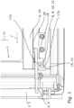
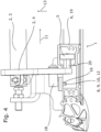
- the swing-sliding door arrangement of the Fig. 1 to 4 is for a vehicle not shown here. It has a door leaf 1, which in the illustration of the Fig. 1 to 4 is in a closed position and closes a door opening - which is also not shown as such here.
- the pivoting sliding door arrangement further comprises a rotary column arrangement 2 with which the door leaf can be adjusted between this closed position and a sliding position - not shown here.
- the rotary column arrangement 2 comprises a rotary column 3, of which only the lower part is shown, and a rotary column lever 4.
- the rotary column lever 4 is pivotally mounted on the rotary column 3 at its end on the rotary column side and has a guide element 5 at its end on the door leaf side.
- This guide element 5 is a guide roller with a vertical axis of rotation, which engages in a linear bearing 6 of the door leaf 1. This engagement serves to linearly guide the door leaf 1 in a horizontal sliding direction 7, which sliding direction 7 can also be referred to as the Y direction and which corresponds to the direction of travel of the vehicle.
- the rotary column lever 4 has a Y-fixing device 8, which fixes the door leaf 1 in the sliding direction 7 and is in positive engagement with the door leaf 1.
- the Y-fixing device 8 is a hook 9. It can also be seen that pivoting the rotary column 3 in an anti-clockwise direction according to the illustration of the Fig.3 by the resulting actuation of the rotary column lever 4, the hook 9 is disengaged from the door leaf 1 and the door leaf 1 is moved into the sliding position. In this case, the bending of the hook runs counter to this direction in a clockwise direction as shown in the Fig.3 .
- the hook 9 simultaneously forms a Z-fixing device 10.
- the hook 9 engages with the door leaf 1, so that along the Z-direction 11 a limitation of the movement of the door leaf 1 is achieved by a positive connection of the hook 9 with the door leaf 1. It can be seen that according to the illustration of the Fig. 1 to 4 there is a play along the Z-direction 11 between the hook 9 and the door leaf 1, so that the above intervention may only take place after a certain adjustment path of the door leaf 1.
- the hook 9 forms an X-pressing device 12, since the engagement of the hook 9 with the door leaf 1 recognizably presses the door leaf 1 along an X-direction 13, which X-direction 13 runs transversely both to the displacement direction 7 and to the Y-direction 11. In this way, the door leaf is pressed both against another door leaf (not shown here) and against a portal (also not shown here) for limiting the door opening.
- the door leaf 1 has an opening 14 for receiving the Y-fixing device 10, which is an elongated hole 15 arranged below the linear bearing 6 in an end region of the linear bearing 6 and aligned along the displacement direction 11.
- the pivoting of the rotary column 3 described above actuates the rotary column lever 4 in such a way that the hook 9 is adjusted into the elongated hole 15.
- the hook 9 specifically engages behind an engagement edge 16 of the elongated hole 15.
- the positive connection of the hook 9 for fixation in the Z direction 11 takes place with secondary edges 17a, b of the elongated hole 15, which delimit the engagement edge 15 vertically at the top and bottom.
- the hook 9 is arranged on a vertically downward oriented pin 18 of the rotary column lever 4.
- the linear bearing 6 is in this case a longitudinal profile 19, which - as can be seen in particular from the Fig.4 visible - is only open in the vertically lower Z direction 11.
- the guide element 5 is rotatably mounted on an axis 20 of the rotary column lever 4, which extends along this Z direction 11 into the longitudinal profile 19.
Landscapes
- Engineering & Computer Science (AREA)
- Mechanical Engineering (AREA)
- Lock And Its Accessories (AREA)
- Hinges (AREA)
Description
- Die Erfindung betrifft eine Schwenkschiebetüranordnung für ein Fahrzeug mit den Merkmalen des Oberbegriffs von Anspruch 1.
- Es hat sich herausgestellt, dass bei Schwenkschiebetüren im geschlossenen Zustand die Türflügel auch gegenüber einer Bewegung in vertikaler Richtung, welche vertikale Richtung auch als Z-Richtung bezeichnet wird, fixiert werden sollten. Im Fahrbetrieb können regelmäßig Schwingungen entstehen, welche auch den Türflügel in Z-Richtung schwingen lassen.
- Ein möglicher Ansatz der Fixierung des Türflügels in Z-Richtung sieht dabei vor, dass an einem unteren Drehsäulenlager der Schwenkschiebetür eine waagrechte Nut vorgesehen ist, welche entlang einer Verschieberichtung des Türflügels der Schwenkschiebetür verläuft. Beim Schließen der Tür fährt ein am Türflügel befestigter Einlaufkeil in diese Nut ein, sodass Schwingungen des Türflügels in Z-Richtung blockiert werden. Diese Verschieberichtung entspricht regelmäßig einer Fahrtrichtung bzw. einer Längsrichtung des Fahrzeugs, weswegen sie hier und nachfolgend auch als Y-Richtung bezeichnet wird.
- Nachteilig an diesem Ansatz ist jedoch, dass Schwingungen des Türflügels sowohl in der Y-Richtung des Türflügels als auch in einer X-Richtung, welche X-Richtung zu dieser Y-Richtung und zu der Z-Richtung senkrecht ist, dazu führen können, dass der oben beschriebene Eingriff zwischen dem Einlaufkeil und der Nut zur Fixierung des Türflügels in Z-Richtung wieder gelöst wird. Diese Situation kann insbesondere während des Fahrbetriebs des Fahrzeugs zu Schäden an der Schwenkschiebetür oder an ihrem Antrieb führen.
- Die
CH 458 111 A - Die
DE 21 11 911 A1 aus dem Stand der Technik zeigt eine Schwenk- und Verriegelungseinrichtung für Laderaumtüren von Kühlwagen, welche aus die Laderaumtür tragenden, paarig angeordneten und seitlich verfahrbaren Schwenkwellen und mit den Schwenkwellen kombinierten Verriegelungswellen zum Anpressen und Abdrücken der Tür an bzw. von deren Dichtungen besteht, dadurch gekennzeichnet, dass die in bekannter Weise als Hohlwelle mit nockenartigen Hebeln ausgebildeten Verriegelungswellen an ihren unteren Enden gegen Verdrehen gesicherte Indexscheiben tragen. - Die
FR 2 814 489 A1 - Die
DE 10 2004 045 072 A1 aus dem Stand der Technik, von welcher die vorliegende Erfindung ausgeht, offenbart eine Schwenktür umfassend mindestens einen Türflügel, wobei der mindestens eine Türflügel im Bereich der Nebenschließkante an einer Drehsäule angelenkt ist, wobei die Drehsäule zur Verbindung mit dem Türflügel mindestens einen Schwenkarm aufweist, wobei bei Drehung der Drehsäule ein Finger in den Bereich der Nebenschließkante des Türflügels bringbar ist, wobei bei geschlossenem Türflügel durch den Finger die Bewegung des Türflügels in Richtung der Fahrzeuglängsachse blockiert ist. - Vor diesem Hintergrund besteht die Aufgabe der Erfindung darin, eine Schwenkschiebetüranordnung bereitzustellen, welche auf kostengünstige und zuverlässige Weise gegen ein Lösen ihrer Z-Fixierung gesichert ist.
- Bezogen auf eine Schwenkschiebetüranordnung für ein Fahrzeug mit den Merkmalen des Oberbegriffs von Anspruch 1 wird diese Aufgabe durch die Merkmale des kennzeichnenden Teils von Anspruch 1 gelöst.
- Wesentlich für die Erfindung ist die Erkenntnis, dass an dem Drehsäulenhebel, welcher die Drehsäule mit dem Türflügel zum Ausstellen des Türflügels bei Entriegelung der Schwenkschiebetür koppelt, eine Vorrichtung vorgesehen sein kann, welche in einer Schließstellung des Türflügels in der Y-Richtung den Türflügel fixiert. Auf diese Weise wird also eine Bewegung des Türflügels in der Y-Richtung unterbunden, sodass ein Lösen der Z-Fixierung durch Bewegungen in der Y-Richtung verhindert wird.
- Die erfindungsgemäße Schwenkschiebetüranordnung ist für ein Fahrzeug bestimmt, wobei es sich insbesondere um ein Fahrzeug des öffentlichen Personenverkehrs handeln kann. Die vorschlagsgemäße Schwenkschiebetüranordnung weist einen Türflügel zum Öffnen und Verschließen einer Türöffnung und eine Drehsäulenanordnung zum Verstellen des Türflügels zwischen einer Schließstellung und einer Verschiebestellung auf. Vorschlagsgemäß weist dabei die Drehsäulenanordnung eine zum Verstellen des Türflügels schwenkbare Drehsäule und einen Drehsäulenhebel zum Koppeln der Drehsäule mit dem Türflügel auf, wobei der Türflügel ein Linearlager aufweist. Vorschlagsgemäß greift in das Linearlager ein Führungselement des Drehsäulenhebels zur Linearführung des Türflügels in eine Verschieberichtung ein, wobei der Türflügel in der Schließstellung die Türöffnung verschließt und in der Verschiebestellung zum Öffnen der Türöffnung entlang der Verschieberichtung verschoben werden kann. Dabei kann es sein, dass bei bestimmten Positionen der Verschiebung des Türflügels entlang der Verschieberichtung eine Verstellung des Türflügels in die Schließstellung nicht möglich ist. Mit anderen Worten kann es sein, dass nur in einer oder mehr bestimmten Positionen der Verschiebung des Türflügels entlang der Verschieberichtung durch die Drehsäulenanordnung der Türflügel in die Schließstellung verstellt werden kann. Bezüglich des Linearlagers und des Führungselements ließe sich auch feststellen, dass das Linearlager des Türflügels und das Führungselement des Drehsäulenhebels eine Linearführung bilden.
- Die erfindungsgemäße Schwenkschiebetüranordnung ist dadurch gekennzeichnet, dass der Drehsäulenhebel eine Y-Fixierungsvorrichtung aufweist, welche zum Fixieren des Türflügels in der Verschieberichtung mit dem Türflügel in der Schließstellung des Türflügels in Eingriff steht. Mit anderen Worten bewirkt der Eingriff der Y-Fixierungsvorrichtung des Drehsäulenhebels mit dem Türflügel, dass eine Relativbewegung des Türflügels zu der Drehsäulenanordnung in der Verschieberichtung verhindert wird. Vorzugsweise bilden die Y-Fixierungsvorrichtung und der Türflügel einen Formschluss in Verschieberichtung durch den Eingriff. Dieses Verhindern der Bewegung kann eine Bewegung entlang einer ersten Ausrichtung der Verschieberichtung oder entlang einer zweiten, der ersten Ausrichtung entgegengesetzten Ausrichtung der Verschieberichtung betreffen. Sofern die Verschieberichtung also durch einen Vektor definiert wird, kann das Verhindern entweder eine zu diesem Vektor parallele oder eine zu diesem Vektor antiparallele Bewegung betreffen.
- Eine bevorzugte Ausführungsform ist dadurch gekennzeichnet, dass die Verschieberichtung bezogen auf das Fahrzeug horizontal verläuft. Hier kann es insbesondere sein, dass die Verschieberichtung kollinear zu einer Fahrtrichtung des Fahrzeugs verläuft. Entsprechend umfasst dies sowohl eine zu der Fahrtrichtung parallele als auch eine zu der Fahrtrichtung antiparallele Ausrichtung der Verschieberichtung. Die Verschieberichtung kann - wie obenstehend bereits erwähnt - auch als Y-Richtung bezeichnet werden.
- Die erfindungsgemäße Schwenkschiebetüranordnung ist weiter dadurch gekennzeichnet, dass die Y-Fixierungsvorrichtung in der Verschiebestellung des Türflügels außer Eingriff mit dem Türflügel steht. Dabei ist vorgesehen, dass die Y-Fixierungsvorrichtung durch Verschwenken der Drehsäule mit dem Türflügel wechselweise in und außer Eingriff gebracht werden kann, wobei das Verschwenken der Drehsäule den Drehsäulenhebel betätigt, sodass die Y-Fixierungsvorrichtung mit dem Türflügel wechselweise in und außer Eingriff gebracht wird. Dabei kann es weiter sein, dass nur in denjenigen Positionen der Verschiebung des Türflügels entlang der Verschieberichtung, in welchen der Türflügel durch die Drehsäulenanordnung in die Schließstellung verstellt werden kann, die Y-Fixierungsvorrichtung durch Verschwenken der Drehsäule mit dem Türflügel in Eingriff gebracht werden kann.
- Gemäß einer bevorzugten Ausführungsform ist vorgesehen, dass die Drehsäulenanordnung eine Z-Fixierungsvorrichtung aufweist, welche zum Begrenzen einer Bewegung des Türflügels in einer Z-Richtung quer zu der Verschieberichtung mit dem Türflügel in der Schließstellung des Türflügels in Eingriff kommt. Dabei ist es bevorzugt, dass die Z-Richtung bezogen auf das Fahrzeug vertikal verläuft. Prinzipiell kommen eine beliebige Ausrichtung oder beide Ausrichtungen dieses vertikalen Verlaufs für die Ausrichtung des Eingriffs infrage. Bevorzugt ist jedoch, dass die Z-Fixierungsvorrichtung zum Begrenzen einer Bewegung des Türflügels in einer oberen Z-Richtung und einer unteren Z-Richtung mit dem Türflügel in Eingriff kommt. Dabei kann dieser Eingriff wechselweise erfolgen und dies insbesondere in Abhängigkeit von den Schwingungen, die der Türflügel erfährt. Vorzugsweise entspricht dieses Begrenzen einer Bewegung des Türflügels einem ggf. spielbehafteten Fixieren des Türflügels.
- Grundsätzlich kann die obige Z-Fixierungsvorrichtung separat und unabhängig zu der Y-Fixierungsvorrichtung ausgestaltet sein. Eine diesbezüglich bevorzugte Ausführungsform ist jedoch dadurch gekennzeichnet, dass die Y-Fixierungsvorrichtung die Z-Fixierungsvorrichtung umfasst. Die Y-Fixierungsvorrichtung kann auch identisch zu der Z-Fixierungsvorrichtung sein. Insbesondere kann es sein, dass der Eingriff der Y-Fixierungsvorrichtung mit dem Türflügel den Türflügel in der Z-Richtung fixiert.
- Eine weitere bevorzugte Ausführungsform ist dadurch gekennzeichnet, dass die Drehsäulenanordnung eine X-Andrückvorrichtung aufweist, welche mit dem Türflügel in der Schließstellung des Türflügels zum Andrücken des Türflügels entlang einer X-Richtung in Eingriff steht. Prinzipiell kann es sich bei dieser X-Richtung um eine beliebige Richtung handeln. Bevorzugt ist es jedoch, dass die X-Richtung senkrecht zu der Verschieberichtung und senkrecht zu der Z-Richtung verläuft. Weiter kann es sein dass die X-Richtung bezogen auf das Fahrzeug horizontal verläuft. Bei der X-Richtung kann es sich also um eine horizontale Richtung handeln, welche quer zu der Y-Richtung verläuft. Dabei kann die Y-Fixierungsvorrichtung auch die X-Andrückvorrichtung umfassen oder aus ihr bestehen.
- Weiter ist es bevorzugt, dass das Linearlager an einem unteren Ende des Türflügels angeordnet ist. Entsprechend handelt es sich dann bei dem Drehsäulenhebel um einen unteren Drehsäulenhebel.
- Gemäß einer bevorzugten Ausführungsform ist vorgesehen dass die Schwenkschiebtüranordnung einen weiteren Türflügel zum Öffnen und Verschließen der Türöffnung aufweist, dass der weitere Türflügel zwischen einer Schließstellung und einer Verschiebestellung verstellt werden kann, dass der weitere Türflügel in der Schließstellung gemeinsam mit dem Türflügel in der Schließstellung die Türöffnung abdeckt und dass die X-Andrückvorrichtung den Türflügel in der Schließstellung gegen den weiteren Türflügel in der Schließstellung drückt. Ebenso kann es sein, dass die Schwenkschiebetüranordnung ein Portal zum Begrenzen der Türöffnung aufweist und dass die X-Andrückvorrichtung den Türflügel in der Schließstellung gegen das Portal drückt. Bei diesem Portal handelt sich also um eine beliebige Struktur, welche ganz oder teilweise die Begrenzung der Türöffnung bildet.
- Die erfindungsgemäße Schwenkschiebetüranordnung ist dadurch gekennzeichnet, dass der Türflügel eine Öffnung zur Aufnahme der Y-Fixierungsvorrichtung aufweist und dass zum Eingriff mit dem Türflügel die Y-Fixierungsvorrichtung in die Öffnung verstellt wird. Mit anderen Worten bewegt sich die Y-Fixierungsvorrichtung in die Öffnung, um mit dem Türflügel in Eingriff zu kommen. Dabei erfolgt die Verstellung der Y-Fixierungsvorrichtung durch eine Betätigung des Drehsäulenhebels, welche Betätigung wiederum durch ein Verschwenken der Drehsäule bewirkt werden kann. Hier ist es bevorzugt, dass die Öffnung in einem Endbereich des Linearlagers und benachbart zu dem Linearlager angeordnet ist.
- Die erfindungsgemäße Schwenkschiebetüranordnung ist weiter dadurch gekennzeichnet, dass die Y-Fixierungsvorrichtung einen Haken für den Eingriff mit dem Türflügel aufweist und dass beim Eingriff der Y-Fixierungsvorrichtung der Haken einen Eingriffsrand der Öffnung hintergreift. Der Eingriff kann also speziell zwischen dem Haken und dem Eingriffsrand der Öffnung bestehen. Indem der Eingriffsrand einen Rand der Öffnung in Verschieberichtung bildet, kann durch den Eingriff der Y-Fixierungsvorrichtung mit dem Eingriffsrand die Fixierung in der Verschieberichtung bewirkt werden. Zwischen dem Haken und dem Eingriffsrand kann durch den Eingriff ein Formschluss in Verschieberichtung bestehen. Erfindungsgemäß hintergreift der Haken den Eingriffsrand der Öffnung zum Andrücken des Türflügels entlang der X-Richtung. Folglich kann die X-Andrückvorrichtung den Haken umfassen.
- Gemäß einer bevorzugten Ausführungsform ist vorgesehen, dass die Öffnung ein Langloch ist, welches entlang der Verschieberichtung ausgerichtet ist. Dabei ist vorzugsweise die Öffnung unterhalb des Linearlagers angeordnet.
- Eine bevorzugte Ausführungsform ist dadurch gekennzeichnet, dass den Eingriffsrand begrenzende Nebenränder der Öffnung durch einen Formschluss mit dem Haken eine Relativbewegung des Hakens zu der Öffnung quer zu der Verschieberichtung, insbesondere entlang beider Ausrichtungen der Z-Richtung, blockieren. Bei diesen Nebenrändern handelt es sich um Ränder der Öffnung, welche den Eingriffsrand begrenzen und insbesondere winklig - also nicht kollinear - zu dem Eingriffsrand verlaufen. Insbesondere können die Nebenränder im Wesentlichen senkrecht zu dem Eingriffsrand verlaufen. Weiter kann es sein, dass ein Spiel des Hakens in der Öffnung in Z-Richtung kleiner als ein Spiel des Führungselements in dem Linearlager in Z-Richtung ist. Auf diese Weise wird trotz des Vorhandenseins eines Spiels des Hakens in Z-Richtung verhindert, dass das Führungselement aus dem Linearlager austritt.
- Eine weitere bevorzugte Ausführungsform ist dadurch gekennzeichnet, dass der Haken an einem Stift des Drehsäulenhebels angeordnet ist. Dabei kann der Haken eine Erstreckung senkrecht zu einer Längsrichtung des Stifts aufweisen. Bevorzugt ist hier weiter, dass der Haken näher an einem türflügelseitigen Ende des Drehsäulenhebels angeordnet ist und insbesondere, dass der Stift vertikal nach unten ausgerichtet ist.
- Gemäß einer bevorzugten Ausführungsform ist vorgesehen, dass der Haken im Wesentlichen entlang einer horizontalen Ebene des Fahrzeugs ausgerichtet ist. Soweit der Haken also gebogen ausgestaltet ist, liegt die die Biegung beschreibende Kurve im Wesentlichen in der horizontalen Ebene des Fahrzeugs. Vorzugsweise ist es weiter so, dass der Haken in eine Richtung gebogen ist, welche einer Schwenkrichtung der Drehsäule zum Verstellen des Türflügels in die Schließstellung entspricht. Wenn also die Drehsäule im Uhrzeigersinn geschwenkt wird, um den Türflügel in die Schließstellung zu verstellen, so ist der Haken vorzugsweise ebenfalls im Uhrzeigersinn gebogen und umgekehrt. Der Verweis auf die Schwenkrichtung bzw. die Biegerichtung ist auf die gemeinsame Ebene des Verschwenkens der Drehsäule und der Biegung des Hakens bezogen.
- Eine bevorzugte Ausführungsform ist dadurch gekennzeichnet, dass der Drehsäulenhebel schwenkbar an der Drehsäule gelagert ist. Vorzugsweise ist der Drehsäulenhebel mit dem Führungselement in dem Linearlager verstellbar gelagert. Bei dieser Verstellung handelt es sich insbesondere um eine lineare Bewegung in Verschieberichtung. Grundsätzlich kann das Linearlager ein Gleitlager sein, sodass das Führungselement ein Gleitelement zur Lineargleitführung des Türflügels aufweisen kann. Bevorzugt ist, dass das Führungselement ein Wälzelement zur Linearwälzführung des Türflügels aufweist.
- Eine weitere bevorzugte Ausführungsform ist dadurch gekennzeichnet, dass das Linearlager ein Längsprofil aufweist. Dabei handelt es sich vorzugsweise um ein längliches Profilelement. Das Linearlager kann auch aus einem solchen Längsprofil bestehen. Bevorzugt ist weiter, dass ein Profilquerschnitt des Längsprofils nur in einer ersten Querrichtung offen ist. Vorzugsweise ist der Profilquerschnitt somit in drei zu dieser Querrichtung senkrecht ausgerichteten Richtungen geschlossen. Das gewährleistet eine sichere Aufnahme des Führungselements in dem Linearlager. Weiter kann es sein, dass das Wälzelement an einer Achse des Drehsäulenhebels drehbar gelagert ist, welche Achse entlang der Querrichtung in das Längsprofil hineinragt und welche Achse an einem türflügelseitigen Ende des Drehsäulenhebels angeordnet ist.
- Weitere vorteilhafte und bevorzugte Ausgestaltungen und Merkmale ergeben sich aus der nachfolgenden Beschreibung mit Bezug auf die Figuren. In der lediglich ein Ausführungsbeispiel wiedergebenden Zeichnung zeigt
- Fig. 1
- eine Ansicht einer erfindungsgemäßen Schwenkschiebetüranordnung aus einer Innenrichtung des Fahrzeugs,
- Fig. 2
- eine Perspektivansicht der Schwenkschiebetüranordnung der
Fig. 1 aus einer schräg unteren Innenrichtung des Fahrzeugs, - Fig. 3
- eine obere Schnittansicht der Schwenkschiebetüranordnung der
Fig. 1 und - Fig. 4
- eine Schnittansicht der Schwenkschiebetüranordnung der
Fig. 1 quer zu einer Längsrichtung des Fahrzeugs. - Die Schwenkschiebetüranordnung der
Fig. 1 bis 4 ist für ein hier nicht dargestelltes Fahrzeug. Sie weist einen Türflügel 1 auf, welcher sich in der Darstellung derFig. 1 bis 4 in einer Schließstellung befindet und eine - hier ebenfalls nicht als solche insgesamt dargestellte - Türöffnung verschließt. Die Schwenkschiebetüranordnung weist ferner eine Drehsäulenanordnung 2 auf, mit welcher der Türflügel zwischen dieser Schließstellung und einer - hier nicht dargestellten - Verschiebestellung verstellt werden kann. Hierzu weist die Drehsäulenanordnung 2 eine Drehsäule 3, von welcher nur der untere Teil dargestellt ist, und einen Drehsäulenhebel 4 auf. Der Drehsäulenhebel 4 ist an seinem drehsäulenseitigen Ende schwenkbar an der Drehsäule 3 gelagert und weist an seinem türflügelseitigen Ende ein Führungselement 5 auf. Bei diesem Führungselement 5 handelt es sich um eine Führungsrolle mit vertikaler Drehachse, welche in ein Linearlager 6 des Türflügels 1 eingreift. Dieser Eingriff dient der Linearführung des Türflügels 1 in eine horizontale Verschieberichtung 7, welche Verschieberichtung 7 auch als Y-Richtung bezeichnet werden kann und welche der Fahrtrichtung des Fahrzeugs entspricht. Der Drehsäulenhebel 4 weist eine Y-Fixierungsvorrichtung 8 auf, welche den Türflügel 1 in der Verschieberichtung 7 fixiert und dazu mit dem Türflügel 1 in formschlüssigem Eingriff steht. - Erkennbar ist, dass eine Verschiebung des Türflügels in die Verschieberichtung 7 gemäß der Darstellung der
Fig. 1 und derFig. 3 durch diesen Eingriff blockiert wird. Bei der Y-Fixierungsvorrichtung 8 handelt es sich vorliegend um einen Haken 9. Ebenso ist erkennbar, dass ein Verschwenken der Drehsäule 3 entgegen dem Uhrzeigersinn gemäß der Darstellung derFig. 3 durch die resultierende Betätigung des Drehsäulenhebels 4 den Haken 9 außer Eingriff mit dem Türflügel 1 bringt und den Türflügel 1 in die Verschiebestellung verstellt. Dabei verläuft insoweit dieser Richtung entgegengesetzt die Biegung des Hakens im Uhrzeigersinn gemäß der Darstellung derFig. 3 . - Der Haken 9 bildet gleichzeitig eine Z-Fixierungsvorrichtung 10. In vertikaler, und zwar sowohl oberer als auch unterer Z-Richtung 11 kommt der Haken 9 mit dem Türflügel 1 in Eingriff, sodass entlang der Z-Richtung 11 durch einen Formschluss des Hakens 9 mit dem Türflügel 1 eine Begrenzung der Bewegung des Türflügels 1 erreicht wird. Erkennbar ist, dass gemäß der Darstellung der
Fig. 1 bis 4 ein Spiel entlang der Z-Richtung 11 zwischen dem Haken 9 und dem Türflügel 1 vorhanden ist, sodass der obige Eingriff ggf. erst nach einem gewissen Verstellweg des Türflügels 1 erfolgt. - Ebenso bildet der Haken 9 eine X-Andrückvorrichtung 12, da der Eingriff des Hakens 9 mit dem Türflügel 1 erkennbar den Türflügel 1 entlang einer X-Richtung 13 andrückt, welche X-Richtung 13 quer sowohl zu der Verschieberichtung 7 als auch zu der Y-Richtung 11 verläuft. Auf diese Weise wird der Türflügel sowohl gegen einen hier nicht dargestellten weiteren Türflügel als auch gegen ein hier ebenfalls nicht dargestelltes Portal zum Begrenzen der Türöffnung gedrückt.
- Bezüglich des Eingriffs des Hakens 9 mit dem Türflügel 1 ist zu erkennen, dass der Türflügel 1 eine Öffnung 14 zur Aufnahme der Y-Fixierungsvorrichtung 10 aufweist, bei welcher es sich um ein unterhalb des Linearlagers 6 in einem Endbereich des Linearlagers 6 angeordnetes und entlang der Verschieberichtung 11 ausgerichtetes Langloch 15 handelt. Das oben beschriebene Verschwenken der Drehsäule 3 betätigt den Drehsäulenhebel 4 derart, dass der Haken 9 in das Langloch 15 verstellt wird. Dabei hintergreift der Haken 9 speziell einen Eingriffsrand 16 des Langlochs 15. Der Formschluss des Hakens 9 zur Fixierung in der Z-Richtung 11 erfolgt mit Nebenrändern 17a, b des Langlochs 15, welche den Eingriffsrand 15 jeweils vertikal oben und unten begrenzen.
- Der Haken 9 ist an einem vertikal nach unten ausgerichteten Stift 18 des Drehsäulenhebels 4 angeordnet. Bei dem Linearlager 6 handelt es sich vorliegend um ein Längsprofil 19, welches - wie insbesondere aus der
Fig. 4 erkennbar - nur in vertikal unterer Z-Richtung 11 offen ist. Das Führungselement 5 ist an einer Achse 20 des Drehsäulenhebels 4 drehbar gelagert, welche sich entlang dieser Z-Richtung 11 in das Längsprofil 19 erstreckt.
Claims (14)
- Schwenkschiebetüranordnung für ein Fahrzeug mit einem Türflügel (1) zum Öffnen und Verschließen einer Türöffnung und mit einer Drehsäulenanordnung (2) zum Verstellen des Türflügels (1) zwischen einer Schließstellung und einer Verschiebestellung, wobei die Drehsäulenanordnung (2) eine zum Verstellen des Türflügels (1) schwenkbare Drehsäule (3) und einen Drehsäulenhebel (4) zum Koppeln der Drehsäule (3) mit dem Türflügel (1) aufweist, wobei der Türflügel (1) ein Linearlager (6) aufweist, in welches ein Führungselement (5) des Drehsäulenhebels (4) zur Linearführung des Türflügels (1) in einer Verschieberichtung (7) eingreift, wobei der Türflügel (1) in der Schließstellung die Türöffnung verschließt und in der Verschiebestellung zum Öffnen der Türöffnung entlang der Verschieberichtung (7) verschoben werden kann und wobei der Drehsäulenhebel (4) eine Y-Fixierungsvorrichtung (8) aufweist, welche zum Fixieren des Türflügels (1) in der Verschieberichtung (7) mit dem Türflügel (1) in der Schließstellung des Türflügels (1) in Eingriff steht, dadurch gekennzeichnet, dass der Türflügel (1) eine Öffnung (14) zur Aufnahme der Y-Fixierungsvorrichtung (10) aufweist, dass zum Eingriff mit dem Türflügel (1) die Y-Fixierungsvorrichtung (10) durch eine Betätigung des Drehsäulenhebels (4) in die Öffnung (14) verstellt wird, dass die Y-Fixierungsvorrichtung (10) einen Haken (9) für den Eingriff mit dem Türflügel (1) aufweist und dass beim Eingriff der Y-Fixierungsvorrichtung (10) der Haken (9) einen Eingriffsrand (16) der Öffnung (14) zum Andrücken des Türflügels (1) entlang einer X-Richtung (13) hintergreift.
- Schwenkschiebetüranordnung nach Anspruch 1, dadurch gekennzeichnet, dass die Verschieberichtung (7) bezogen auf das Fahrzeug horizontal verläuft, insbesondere, dass die Verschieberichtung (7) kollinear zu einer Fahrtrichtung des Fahrzeugs verläuft.
- Schwenkschiebetüranordnung nach Anspruch 1 oder 2, dadurch gekennzeichnet, dass die Y-Fixierungsvorrichtung (7) in der Verschiebestellung des Türflügels (1) außer Eingriff mit dem Türflügel (1) steht, vorzugsweise, dass die Y-Fixierungsvorrichtung (7) durch Verschwenken der Drehsäule (3) mit dem Türflügel (1) wechselweise in und außer Eingriff gebracht werden kann.
- Schwenkschiebetüranordnung nach einem der Ansprüche 1 bis 3, dadurch gekennzeichnet, dass die Drehsäulenanordnung (2) eine Z-Fixierungsvorrichtung (10) aufweist, welche zum Begrenzen einer Bewegung des Türflügels (1) in einer Z-Richtung (11) quer zu der Verschieberichtung (7) mit dem Türflügel (1) in der Schließstellung des Türflügels (1) in Eingriff kommt, vorzugsweise, dass die Z-Richtung (11) bezogen auf das Fahrzeug vertikal verläuft, insbesondere dass die Z-Fixierungsvorrichtung (10) zum Begrenzen einer Bewegung des Türflügels (1) in einer oberen Z-Richtung und einer unteren Z-Richtung mit dem Türflügel (1) in Eingriff kommt.
- Schwenkschiebetüranordnung nach Anspruch 4, dadurch gekennzeichnet, dass die Y-Fixierungsvorrichtung (8) die Z-Fixierungsvorrichtung (11) umfasst, insbesondere, dass der Eingriff der Y-Fixierungsvorrichtung (8) mit dem Türflügel (1) den Türflügel (1) in der Z-Richtung (11) fixiert.
- Schwenkschiebetüranordnung nach einem der Ansprüche 1 bis 5, dadurch gekennzeichnet, dass die Drehsäulenanordnung eine X-Andrückvorrichtung (12) aufweist, welche mit dem Türflügel (1) in der Schließstellung des Türflügels (1) zum Andrücken des Türflügels (1) entlang der X-Richtung (13) in Eingriff steht, vorzugsweise, dass die X-Richtung (13) senkrecht zu der Verschieberichtung (7) und senkrecht zu der Z-Richtung (11) verläuft, insbesondere, dass die X-Richtung (13) bezogen auf das Fahrzeug horizontal verläuft.
- Schwenkschiebtüranordnung nach Anspruch 6, dadurch gekennzeichnet, dass die Schwenkschiebtüranordnung einen weiteren Türflügel zum Öffnen und Verschließen der Türöffnung aufweist, dass der weitere Türflügel zwischen einer Schließstellung und einer Verschiebestellung verstellt werden kann, dass der weitere Türflügel in der Schließstellung gemeinsam mit dem Türflügel (1) in der Schließstellung die Türöffnung abdeckt und dass die X-Andrückvorrichtung (12) den Türflügel (1) in der Schließstellung gegen den weiteren Türflügel in der Schließstellung drückt, vorzugsweise, dass die Schwenkschiebetüranordnung ein Portal zum Begrenzen der Türöffnung aufweist und dass die X-Andrückvorrichtung den Türflügel (1) in der Schließstellung gegen das Portal drückt.
- Schwenkschiebetüranordnung nach einem der Ansprüche 1 bis 7, dadurch gekennzeichnet, dass die Öffnung (14) in einem Endbereich des Linearlagers (6) und benachbart zu dem Linearlager (6) angeordnet ist.
- Schwenkschiebetüranordnung nach einem der Ansprüche 1 bis 8, dadurch gekennzeichnet, dass die Öffnung (14) ein Langloch (15) ist, welches entlang der Verschieberichtung (11) ausgerichtet ist, vorzugsweise, dass die Öffnung (14) unterhalb des Linearlagers (6) angeordnet ist.
- Schwenkschiebetüranordnung nach einem der Ansprüche 1 bis 9, dadurch gekennzeichnet, dass den Eingriffsrand (16) begrenzende Nebenränder (17a, b) der Öffnung (14) durch einen Formschluss mit dem Haken (9) eine Relativbewegung des Hakens (9) zu der Öffnung (14) quer zu der Verschieberichtung (7), insbesondere entlang beider Ausrichtungen der Z-Richtung (11), blockieren, insbesondere, dass ein Spiel des Hakens (9) in der Öffnung (14) in Z-Richtung (11) kleiner als ein Spiel des Führungselements (5) in dem Linearlager (6) in Z-Richtung (11) ist.
- Schwenkschiebetüranordnung nach einem der Ansprüche 1 bis 10, dadurch gekennzeichnet, dass der Haken (9) an einem Stift (18) des Drehsäulenhebels (4) angeordnet ist, vorzugsweise, dass der Haken (9) näher an einem türflügelseitigen Ende des Drehsäulenhebels (4) angeordnet ist, insbesondere, dass der Stift (18) vertikal nach unten ausgerichtet ist.
- Schwenkschiebetüranordnung nach einem der Ansprüche 1 bis 11, dadurch gekennzeichnet, dass der Haken (9) im Wesentlichen entlang einer horizontalen Ebene des Fahrzeugs ausgerichtet ist, vorzugsweise dass der Haken (9) in eine Richtung gebogen ist, welche einer Schwenkrichtung der Drehsäule (3) zum Verstellen des Türflügels (1) in die Schließstellung entspricht.
- Schwenkschiebetüranordnung nach einem der Ansprüche 1 bis 12, dadurch gekennzeichnet, dass der Drehsäulenhebel (4) schwenkbar an der Drehsäule (3) gelagert ist, vorzugsweise, dass der Drehsäulenhebel (4) mit dem Führungselement (5) in dem Linearlager (6) verstellbar gelagert ist, insbesondere, dass das Führungselement (5) ein Wälzelement zur Linearwälzführung des Türflügels (1) aufweist.
- Schwenkschiebetüranordnung nach Anspruch 13, dadurch gekennzeichnet, dass das Linearlager (6) ein Längsprofil (19) aufweist, vorzugsweise, dass ein Profilquerschnitt des Längsprofils (19) nur in einer ersten Querrichtung offen ist, insbesondere, dass das Wälzelement an einer Achse (20) des Drehsäulenhebels (4) drehbar gelagert ist, welche Achse (20) entlang der Querrichtung in das Längsprofil (19) hineinragt und an einem türflügelseitigen Ende des Drehsäulenhebels (4) angeordnet ist.
Applications Claiming Priority (1)
| Application Number | Priority Date | Filing Date | Title |
|---|---|---|---|
| DE202016105214.9U DE202016105214U1 (de) | 2016-09-19 | 2016-09-19 | Schwenkschiebetüranordnung für ein Fahrzeug |
Publications (3)
| Publication Number | Publication Date |
|---|---|
| EP3296497A1 EP3296497A1 (de) | 2018-03-21 |
| EP3296497B1 true EP3296497B1 (de) | 2024-08-14 |
| EP3296497C0 EP3296497C0 (de) | 2024-08-14 |
Family
ID=59895209
Family Applications (1)
| Application Number | Title | Priority Date | Filing Date |
|---|---|---|---|
| EP17191528.3A Active EP3296497B1 (de) | 2016-09-19 | 2017-09-18 | Schwenkschiebetüranordnung für ein fahrzeug |
Country Status (3)
| Country | Link |
|---|---|
| US (1) | US20180080268A1 (de) |
| EP (1) | EP3296497B1 (de) |
| DE (1) | DE202016105214U1 (de) |
Families Citing this family (2)
| Publication number | Priority date | Publication date | Assignee | Title |
|---|---|---|---|---|
| CN110578442B (zh) * | 2019-09-27 | 2023-11-17 | 厦门威迪思汽车设计服务有限公司 | 一种公交车塞拉门机构 |
| EP4613960A1 (de) * | 2024-03-05 | 2025-09-10 | Bode - Die Tür GmbH | Zwei-rollen-schwenkarm |
Citations (1)
| Publication number | Priority date | Publication date | Assignee | Title |
|---|---|---|---|---|
| DE102004045072A1 (de) * | 2004-09-15 | 2006-03-30 | Hübner GmbH | Schwenktür eines Busses oder eines schienengebundenen Fahrzeuges, umfassend mindestens einen Türflügel |
Family Cites Families (21)
| Publication number | Priority date | Publication date | Assignee | Title |
|---|---|---|---|---|
| US303101A (en) * | 1884-08-05 | Car-door lock | ||
| US955537A (en) * | 1908-11-30 | 1910-04-19 | David F Noll | Flush-car-door supporting and operating means. |
| US2570563A (en) * | 1945-04-16 | 1951-10-09 | Lockheed Aircraft Corp | Operating means for sliding doors |
| US3245125A (en) * | 1964-07-06 | 1966-04-12 | Youngstown Steel Door Co | Door |
| US3318048A (en) * | 1965-05-27 | 1967-05-09 | Jamison Cold Storage Door Comp | Combination guide and latch roller |
| AT306757B (de) * | 1966-03-17 | 1973-03-15 | Dessau Waggonbau Veb | Kuehlraumtuer,insbesondere laderaumtuer fuer kuehlwagen |
| CH458111A (de) * | 1967-08-14 | 1968-06-15 | Miner Inc W H | Schiebetür-Betätigungsmechanismus |
| DE2022487A1 (de) * | 1970-05-08 | 1971-12-02 | Arnold Kiekert Soehne | Schwenkschiebetuer fuer Fahrzeuge |
| US3923327A (en) * | 1971-07-26 | 1975-12-02 | Youngstown Steel Door Co | Sealing cam interlock |
| ATE95764T1 (de) * | 1989-06-02 | 1993-10-15 | Ife Gmbh | Schwenkschiebetuer fuer fahrzeuge. |
| IT1237743B (it) * | 1989-12-22 | 1993-06-15 | Fiat Auto Spa | Dispositivo di traslazione per un porta scorrevole di un veicolo. |
| US5046544A (en) * | 1990-06-08 | 1991-09-10 | Joseph Coluccio | Rollup door vibrating damping device for trucks and the like |
| DE4314115A1 (de) * | 1993-04-29 | 1994-11-03 | Opel Adam Ag | Schiebetür, insbesondere für Kraftfahrzeuge |
| US5836111A (en) * | 1996-04-16 | 1998-11-17 | Fine Industries, Inc. | Opening-closing device for windows |
| FR2814489B1 (fr) * | 2000-09-26 | 2004-07-02 | Peugeot Citroen Automobiles Sa | Dispositif d'ouverture laterale d'un vehicule automobile comprenant au moins une porte coulissante |
| AT501468B8 (de) * | 2005-02-17 | 2007-02-15 | Knorr Bremse Gmbh | Schwenkschiebetür |
| DE102006036412A1 (de) * | 2005-09-06 | 2007-03-08 | Kiekert Ag | Vorrichtung zum Bewegen einer Schiebetür mit einer Notbetätigung |
| CN105863428B (zh) * | 2011-03-10 | 2018-01-16 | 纳博特斯克有限公司 | 塞拉门装置 |
| JP6108786B2 (ja) * | 2012-11-21 | 2017-04-05 | 東海旅客鉄道株式会社 | 鉄道車両、および、鉄道車両用プラグドア、プラグ機構 |
| KR101673339B1 (ko) * | 2014-11-03 | 2016-11-07 | 현대자동차 주식회사 | 차량용 슬라이딩 도어 스윙 록킹장치 |
| KR101637289B1 (ko) * | 2014-11-06 | 2016-07-07 | 현대자동차 주식회사 | 차량용 슬라이딩 도어장치 |
-
2016
- 2016-09-19 DE DE202016105214.9U patent/DE202016105214U1/de not_active Expired - Lifetime
-
2017
- 2017-09-18 EP EP17191528.3A patent/EP3296497B1/de active Active
- 2017-09-19 US US15/708,613 patent/US20180080268A1/en not_active Abandoned
Patent Citations (1)
| Publication number | Priority date | Publication date | Assignee | Title |
|---|---|---|---|---|
| DE102004045072A1 (de) * | 2004-09-15 | 2006-03-30 | Hübner GmbH | Schwenktür eines Busses oder eines schienengebundenen Fahrzeuges, umfassend mindestens einen Türflügel |
Also Published As
| Publication number | Publication date |
|---|---|
| US20180080268A1 (en) | 2018-03-22 |
| EP3296497A1 (de) | 2018-03-21 |
| EP3296497C0 (de) | 2024-08-14 |
| DE202016105214U1 (de) | 2017-12-21 |
Similar Documents
| Publication | Publication Date | Title |
|---|---|---|
| AT501468B1 (de) | Schwenkschiebetür | |
| DE112013001849T5 (de) | Einbaustruktur für ein bewegbares Fenster eines Schiebefenstersystems mit einer Aluminiumlegierung-Rahmenstruktur | |
| DE102005048786A1 (de) | Türe, insbesondere für ein Kraftfahrzeug | |
| EP1767388A2 (de) | Schwenkschiebetür für Fahrzeuge, insbesondere Fahrgasttür für Fahrzeuge des offentlichen Personnenverkehrs | |
| AT515354A1 (de) | Vorrichtung zum Öffnen einer Flugzeugtür | |
| DE19611222C2 (de) | Ausstellmechanismus | |
| WO2003073003A1 (de) | Haushaltsgerät | |
| EP4048122B1 (de) | Anordnung mit antriebsvorrichtung und synchronisierungsvorrichtugn für ausziehführungen für eine schublade | |
| EP2672045B1 (de) | Führungsanordnung einer Schiebetür eines Schiebetürmöbels | |
| DE102011085177B4 (de) | Antriebssystem für ein KFZ-Dachsystem | |
| DE1683704B2 (de) | Vorrichtung zur Betätigung und Abdichtung von schiebbaren oder kipp- und/oder schwenkbaren Flügeln von Fenstern oder Türen | |
| EP3296497A1 (de) | Schwenkschiebetüranordnung für ein fahrzeug | |
| DE3301533C2 (de) | ||
| DE2643854A1 (de) | Seitenwand | |
| DE102004044908B3 (de) | Cabriolet-Fahrzeug | |
| DE102012213786B3 (de) | Verlagerungsanordnung zur Verlagerung eines Flügels eines Fensters, einer Tür oder dergleichen relativ zu einer festen Einfassung | |
| DE10160096C1 (de) | Verschluss zum gegenseitigen Verriegeln zweier Bauteile | |
| DE3316473C2 (de) | Öffnungs- und Schließmechanismus für ein schrägstellbares Sonnendach | |
| DE10301584B4 (de) | Vorrichtung zur verschieblichen Anordnung eines Paneels | |
| DE102012213782B4 (de) | Verlagerungsanordnung zur Verlagerung eines Schiebeflügels eines Fensters, einer Tür oder dergleichen relativ zu einer festen Einfassung mit einem flügelseitigen und einem einfassungsseitigen Steuerelement | |
| EP1561891A2 (de) | Schwenkmechanismus zum Öffnen und Schliessen einer aus einem Türblatt und einem Türrahmen bestehenden Tür, insbesondere einer Fahrzeugtür | |
| DE2428556A1 (de) | Schiebetuervorrichtung | |
| DE19633645C1 (de) | Selbstjustierendes Fahrzeugdach | |
| AT520902B1 (de) | Kreuzspindelantrieb mit Verriegelungsvorrichtung für Schiebetüren und Schwenk-Schiebetüren für Schienenfahrzeuge zum Personentransport | |
| DE3245123A1 (de) | Verschlusskappe fuer oeffnungen in vertikalen waenden |
Legal Events
| Date | Code | Title | Description |
|---|---|---|---|
| PUAI | Public reference made under article 153(3) epc to a published international application that has entered the european phase |
Free format text: ORIGINAL CODE: 0009012 |
|
| STAA | Information on the status of an ep patent application or granted ep patent |
Free format text: STATUS: THE APPLICATION HAS BEEN PUBLISHED |
|
| AK | Designated contracting states |
Kind code of ref document: A1 Designated state(s): AL AT BE BG CH CY CZ DE DK EE ES FI FR GB GR HR HU IE IS IT LI LT LU LV MC MK MT NL NO PL PT RO RS SE SI SK SM TR |
|
| AX | Request for extension of the european patent |
Extension state: BA ME |
|
| STAA | Information on the status of an ep patent application or granted ep patent |
Free format text: STATUS: REQUEST FOR EXAMINATION WAS MADE |
|
| 17P | Request for examination filed |
Effective date: 20180921 |
|
| RBV | Designated contracting states (corrected) |
Designated state(s): AL AT BE BG CH CY CZ DE DK EE ES FI FR GB GR HR HU IE IS IT LI LT LU LV MC MK MT NL NO PL PT RO RS SE SI SK SM TR |
|
| STAA | Information on the status of an ep patent application or granted ep patent |
Free format text: STATUS: EXAMINATION IS IN PROGRESS |
|
| 17Q | First examination report despatched |
Effective date: 20210701 |
|
| RAP3 | Party data changed (applicant data changed or rights of an application transferred) |
Owner name: BODE - DIE TUER GMBH |
|
| GRAP | Despatch of communication of intention to grant a patent |
Free format text: ORIGINAL CODE: EPIDOSNIGR1 |
|
| STAA | Information on the status of an ep patent application or granted ep patent |
Free format text: STATUS: GRANT OF PATENT IS INTENDED |
|
| INTG | Intention to grant announced |
Effective date: 20240419 |
|
| GRAS | Grant fee paid |
Free format text: ORIGINAL CODE: EPIDOSNIGR3 |
|
| GRAA | (expected) grant |
Free format text: ORIGINAL CODE: 0009210 |
|
| STAA | Information on the status of an ep patent application or granted ep patent |
Free format text: STATUS: THE PATENT HAS BEEN GRANTED |
|
| AK | Designated contracting states |
Kind code of ref document: B1 Designated state(s): AL AT BE BG CH CY CZ DE DK EE ES FI FR GB GR HR HU IE IS IT LI LT LU LV MC MK MT NL NO PL PT RO RS SE SI SK SM TR |
|
| REG | Reference to a national code |
Ref country code: GB Ref legal event code: FG4D Free format text: NOT ENGLISH |
|
| REG | Reference to a national code |
Ref country code: CH Ref legal event code: EP |
|
| REG | Reference to a national code |
Ref country code: DE Ref legal event code: R096 Ref document number: 502017016342 Country of ref document: DE |
|
| REG | Reference to a national code |
Ref country code: IE Ref legal event code: FG4D Free format text: LANGUAGE OF EP DOCUMENT: GERMAN |
|
| U01 | Request for unitary effect filed |
Effective date: 20240815 |
|
| U07 | Unitary effect registered |
Designated state(s): AT BE BG DE DK EE FI FR IT LT LU LV MT NL PT SE SI Effective date: 20240828 |
|
| U20 | Renewal fee for the european patent with unitary effect paid |
Year of fee payment: 8 Effective date: 20241108 |
|
| PG25 | Lapsed in a contracting state [announced via postgrant information from national office to epo] |
Ref country code: NO Free format text: LAPSE BECAUSE OF FAILURE TO SUBMIT A TRANSLATION OF THE DESCRIPTION OR TO PAY THE FEE WITHIN THE PRESCRIBED TIME-LIMIT Effective date: 20241114 |
|
| PG25 | Lapsed in a contracting state [announced via postgrant information from national office to epo] |
Ref country code: GR Free format text: LAPSE BECAUSE OF FAILURE TO SUBMIT A TRANSLATION OF THE DESCRIPTION OR TO PAY THE FEE WITHIN THE PRESCRIBED TIME-LIMIT Effective date: 20241115 Ref country code: PL Free format text: LAPSE BECAUSE OF FAILURE TO SUBMIT A TRANSLATION OF THE DESCRIPTION OR TO PAY THE FEE WITHIN THE PRESCRIBED TIME-LIMIT Effective date: 20240814 |
|
| PG25 | Lapsed in a contracting state [announced via postgrant information from national office to epo] |
Ref country code: IS Free format text: LAPSE BECAUSE OF FAILURE TO SUBMIT A TRANSLATION OF THE DESCRIPTION OR TO PAY THE FEE WITHIN THE PRESCRIBED TIME-LIMIT Effective date: 20241214 |
|
| PG25 | Lapsed in a contracting state [announced via postgrant information from national office to epo] |
Ref country code: HR Free format text: LAPSE BECAUSE OF FAILURE TO SUBMIT A TRANSLATION OF THE DESCRIPTION OR TO PAY THE FEE WITHIN THE PRESCRIBED TIME-LIMIT Effective date: 20240814 |
|
| PG25 | Lapsed in a contracting state [announced via postgrant information from national office to epo] |
Ref country code: ES Free format text: LAPSE BECAUSE OF FAILURE TO SUBMIT A TRANSLATION OF THE DESCRIPTION OR TO PAY THE FEE WITHIN THE PRESCRIBED TIME-LIMIT Effective date: 20240814 Ref country code: RS Free format text: LAPSE BECAUSE OF FAILURE TO SUBMIT A TRANSLATION OF THE DESCRIPTION OR TO PAY THE FEE WITHIN THE PRESCRIBED TIME-LIMIT Effective date: 20241114 |
|
| PG25 | Lapsed in a contracting state [announced via postgrant information from national office to epo] |
Ref country code: RS Free format text: LAPSE BECAUSE OF FAILURE TO SUBMIT A TRANSLATION OF THE DESCRIPTION OR TO PAY THE FEE WITHIN THE PRESCRIBED TIME-LIMIT Effective date: 20241114 Ref country code: PL Free format text: LAPSE BECAUSE OF FAILURE TO SUBMIT A TRANSLATION OF THE DESCRIPTION OR TO PAY THE FEE WITHIN THE PRESCRIBED TIME-LIMIT Effective date: 20240814 Ref country code: NO Free format text: LAPSE BECAUSE OF FAILURE TO SUBMIT A TRANSLATION OF THE DESCRIPTION OR TO PAY THE FEE WITHIN THE PRESCRIBED TIME-LIMIT Effective date: 20241114 Ref country code: IS Free format text: LAPSE BECAUSE OF FAILURE TO SUBMIT A TRANSLATION OF THE DESCRIPTION OR TO PAY THE FEE WITHIN THE PRESCRIBED TIME-LIMIT Effective date: 20241214 Ref country code: HR Free format text: LAPSE BECAUSE OF FAILURE TO SUBMIT A TRANSLATION OF THE DESCRIPTION OR TO PAY THE FEE WITHIN THE PRESCRIBED TIME-LIMIT Effective date: 20240814 Ref country code: GR Free format text: LAPSE BECAUSE OF FAILURE TO SUBMIT A TRANSLATION OF THE DESCRIPTION OR TO PAY THE FEE WITHIN THE PRESCRIBED TIME-LIMIT Effective date: 20241115 Ref country code: ES Free format text: LAPSE BECAUSE OF FAILURE TO SUBMIT A TRANSLATION OF THE DESCRIPTION OR TO PAY THE FEE WITHIN THE PRESCRIBED TIME-LIMIT Effective date: 20240814 |
|
| PG25 | Lapsed in a contracting state [announced via postgrant information from national office to epo] |
Ref country code: SM Free format text: LAPSE BECAUSE OF FAILURE TO SUBMIT A TRANSLATION OF THE DESCRIPTION OR TO PAY THE FEE WITHIN THE PRESCRIBED TIME-LIMIT Effective date: 20240814 |
|
| PG25 | Lapsed in a contracting state [announced via postgrant information from national office to epo] |
Ref country code: CZ Free format text: LAPSE BECAUSE OF FAILURE TO SUBMIT A TRANSLATION OF THE DESCRIPTION OR TO PAY THE FEE WITHIN THE PRESCRIBED TIME-LIMIT Effective date: 20240814 |
|
| PG25 | Lapsed in a contracting state [announced via postgrant information from national office to epo] |
Ref country code: SK Free format text: LAPSE BECAUSE OF FAILURE TO SUBMIT A TRANSLATION OF THE DESCRIPTION OR TO PAY THE FEE WITHIN THE PRESCRIBED TIME-LIMIT Effective date: 20240814 |
|
| REG | Reference to a national code |
Ref country code: CH Ref legal event code: PL |
|
| PLBE | No opposition filed within time limit |
Free format text: ORIGINAL CODE: 0009261 |
|
| STAA | Information on the status of an ep patent application or granted ep patent |
Free format text: STATUS: NO OPPOSITION FILED WITHIN TIME LIMIT |
|
| PG25 | Lapsed in a contracting state [announced via postgrant information from national office to epo] |
Ref country code: MC Free format text: LAPSE BECAUSE OF FAILURE TO SUBMIT A TRANSLATION OF THE DESCRIPTION OR TO PAY THE FEE WITHIN THE PRESCRIBED TIME-LIMIT Effective date: 20240814 |
|
| 26N | No opposition filed |
Effective date: 20250515 |
|
| GBPC | Gb: european patent ceased through non-payment of renewal fee |
Effective date: 20241114 |
|
| PG25 | Lapsed in a contracting state [announced via postgrant information from national office to epo] |
Ref country code: CH Free format text: LAPSE BECAUSE OF NON-PAYMENT OF DUE FEES Effective date: 20240930 |
|
| PG25 | Lapsed in a contracting state [announced via postgrant information from national office to epo] |
Ref country code: IE Free format text: LAPSE BECAUSE OF NON-PAYMENT OF DUE FEES Effective date: 20240918 |
|
| PG25 | Lapsed in a contracting state [announced via postgrant information from national office to epo] |
Ref country code: GB Free format text: LAPSE BECAUSE OF NON-PAYMENT OF DUE FEES Effective date: 20241114 |
|
| PG25 | Lapsed in a contracting state [announced via postgrant information from national office to epo] |
Ref country code: RO Free format text: LAPSE BECAUSE OF FAILURE TO SUBMIT A TRANSLATION OF THE DESCRIPTION OR TO PAY THE FEE WITHIN THE PRESCRIBED TIME-LIMIT Effective date: 20240814 |
|
| PG25 | Lapsed in a contracting state [announced via postgrant information from national office to epo] |
Ref country code: CY Free format text: LAPSE BECAUSE OF FAILURE TO SUBMIT A TRANSLATION OF THE DESCRIPTION OR TO PAY THE FEE WITHIN THE PRESCRIBED TIME-LIMIT; INVALID AB INITIO Effective date: 20170918 |
|
| PG25 | Lapsed in a contracting state [announced via postgrant information from national office to epo] |
Ref country code: HU Free format text: LAPSE BECAUSE OF FAILURE TO SUBMIT A TRANSLATION OF THE DESCRIPTION OR TO PAY THE FEE WITHIN THE PRESCRIBED TIME-LIMIT; INVALID AB INITIO Effective date: 20170918 |
|
| U90 | Renewal fees not paid: noting of loss of rights |
Free format text: RENEWAL FEE NOT PAID FOR YEAR 09 Effective date: 20260416 |