EP3287021A2 - Heizelemente für elektronische zigaretten - Google Patents
Heizelemente für elektronische zigaretten Download PDFInfo
- Publication number
- EP3287021A2 EP3287021A2 EP17183310.6A EP17183310A EP3287021A2 EP 3287021 A2 EP3287021 A2 EP 3287021A2 EP 17183310 A EP17183310 A EP 17183310A EP 3287021 A2 EP3287021 A2 EP 3287021A2
- Authority
- EP
- European Patent Office
- Prior art keywords
- heating element
- glass
- carrier material
- element according
- heizleiterstrukturen
- Prior art date
- Legal status (The legal status is an assumption and is not a legal conclusion. Google has not performed a legal analysis and makes no representation as to the accuracy of the status listed.)
- Granted
Links
Images

Classifications
-
- H—ELECTRICITY
- H05—ELECTRIC TECHNIQUES NOT OTHERWISE PROVIDED FOR
- H05B—ELECTRIC HEATING; ELECTRIC LIGHT SOURCES NOT OTHERWISE PROVIDED FOR; CIRCUIT ARRANGEMENTS FOR ELECTRIC LIGHT SOURCES, IN GENERAL
- H05B3/00—Ohmic-resistance heating
- H05B3/20—Heating elements having extended surface area substantially in a two-dimensional [2D] plane, e.g. plate-heater
- H05B3/22—Heating elements having extended surface area substantially in a two-dimensional [2D] plane, e.g. plate-heater non-flexible
- H05B3/26—Heating elements having extended surface area substantially in a two-dimensional [2D] plane, e.g. plate-heater non-flexible heating conductor mounted on insulating base
- H05B3/265—Heating elements having extended surface area substantially in a two-dimensional [2D] plane, e.g. plate-heater non-flexible heating conductor mounted on insulating base the insulating base being an inorganic material, e.g. ceramic
-
- A—HUMAN NECESSITIES
- A24—TOBACCO; CIGARS; CIGARETTES; SIMULATED SMOKING DEVICES; SMOKERS' REQUISITES
- A24F—SMOKERS' REQUISITES; MATCH BOXES; SIMULATED SMOKING DEVICES
- A24F40/00—Electrically operated smoking devices; Component parts thereof; Manufacture thereof; Maintenance or testing thereof; Charging means specially adapted therefor
- A24F40/40—Constructional details, e.g. connection of cartridges and battery parts
- A24F40/46—Shape or structure of electric heating means
-
- H—ELECTRICITY
- H05—ELECTRIC TECHNIQUES NOT OTHERWISE PROVIDED FOR
- H05B—ELECTRIC HEATING; ELECTRIC LIGHT SOURCES NOT OTHERWISE PROVIDED FOR; CIRCUIT ARRANGEMENTS FOR ELECTRIC LIGHT SOURCES, IN GENERAL
- H05B3/00—Ohmic-resistance heating
- H05B3/02—Details
- H05B3/06—Heater elements structurally combined with coupling elements or holders
- H05B3/08—Heater elements structurally combined with coupling elements or holders having electric connections specially adapted for high temperatures
-
- H—ELECTRICITY
- H05—ELECTRIC TECHNIQUES NOT OTHERWISE PROVIDED FOR
- H05B—ELECTRIC HEATING; ELECTRIC LIGHT SOURCES NOT OTHERWISE PROVIDED FOR; CIRCUIT ARRANGEMENTS FOR ELECTRIC LIGHT SOURCES, IN GENERAL
- H05B3/00—Ohmic-resistance heating
- H05B3/40—Heating elements having the shape of rods or tubes
- H05B3/42—Heating elements having the shape of rods or tubes non-flexible
- H05B3/46—Heating elements having the shape of rods or tubes non-flexible heating conductor mounted on insulating base
-
- A—HUMAN NECESSITIES
- A24—TOBACCO; CIGARS; CIGARETTES; SIMULATED SMOKING DEVICES; SMOKERS' REQUISITES
- A24F—SMOKERS' REQUISITES; MATCH BOXES; SIMULATED SMOKING DEVICES
- A24F40/00—Electrically operated smoking devices; Component parts thereof; Manufacture thereof; Maintenance or testing thereof; Charging means specially adapted therefor
- A24F40/10—Devices using liquid inhalable precursors
-
- H—ELECTRICITY
- H05—ELECTRIC TECHNIQUES NOT OTHERWISE PROVIDED FOR
- H05B—ELECTRIC HEATING; ELECTRIC LIGHT SOURCES NOT OTHERWISE PROVIDED FOR; CIRCUIT ARRANGEMENTS FOR ELECTRIC LIGHT SOURCES, IN GENERAL
- H05B2203/00—Aspects relating to Ohmic resistive heating covered by group H05B3/00
- H05B2203/002—Heaters using a particular layout for the resistive material or resistive elements
- H05B2203/003—Heaters using a particular layout for the resistive material or resistive elements using serpentine layout
-
- H—ELECTRICITY
- H05—ELECTRIC TECHNIQUES NOT OTHERWISE PROVIDED FOR
- H05B—ELECTRIC HEATING; ELECTRIC LIGHT SOURCES NOT OTHERWISE PROVIDED FOR; CIRCUIT ARRANGEMENTS FOR ELECTRIC LIGHT SOURCES, IN GENERAL
- H05B2203/00—Aspects relating to Ohmic resistive heating covered by group H05B3/00
- H05B2203/013—Heaters using resistive films or coatings
-
- H—ELECTRICITY
- H05—ELECTRIC TECHNIQUES NOT OTHERWISE PROVIDED FOR
- H05B—ELECTRIC HEATING; ELECTRIC LIGHT SOURCES NOT OTHERWISE PROVIDED FOR; CIRCUIT ARRANGEMENTS FOR ELECTRIC LIGHT SOURCES, IN GENERAL
- H05B2203/00—Aspects relating to Ohmic resistive heating covered by group H05B3/00
- H05B2203/021—Heaters specially adapted for heating liquids
Definitions
- the invention generally relates to a heating element for hot applications.
- the invention relates to a heating element for the controlled heating and evaporation of vaporizable and / or tobacco-containing substances in electronic cigarettes.
- e-cigarettes Electronic cigarettes, also referred to below as e-cigarettes, are increasingly being used as an alternative to tobacco cigarettes.
- e-cigarettes here have a mouthpiece and an evaporator unit comprising a heating element.
- the heating element in this case heats a vaporizable liquid so that it can be inhaled by the user.
- This liquid may already contain nicotine.
- the liquid is nicotine-free.
- the forming aerosol can then flood a nicotine-containing and nicotine-permeable body.
- lance-shaped heating elements are known from the prior art. These are placed in a specially designed piece of tobacco and thus brought into contact with the substances to be evaporated and heat them to temperatures in the range of 50 ° C to 350 ° C. This causes an aerosol formation.
- Corresponding heating lances can consist of a heating wire without carrier material. The disadvantage here, however, that due to the required mechanical stability of the heating element, the dimensions of the heating element can not be made arbitrarily small. Furthermore, corresponding heating elements easily become dirty during use.
- the known ceramic support materials have a high thermal conductivity. This is disadvantageous for use in a heating element, since thus the heat generated in the heating region of the heating element can not be deliberately delivered to the medium to be heated, but a heat dissipation by the ceramic and thus dissipated heat is no longer for the Evaporation or heating of the substances is available. Accordingly, more heating power must be applied by the heating element, which not only adversely affects the energy consumption and thus, for example, on the battery or battery life of the e-cigarette, but also lead to an increase in temperature within the e-cigarette and thus disadvantageous can affect the life of the heating element.
- the heating element within the e-cigarette can also be arranged so that it is not introduced directly into the tobacco piece or the substances to be evaporated, but the tobacco piece or a reservoir with the substances to be vaporized cylindrical enclose.
- a corresponding arrangement is for example in the US 2005/0172976 described.
- Such external heating elements offer the advantage that the substances or tobacco pieces to be evaporated can be exchanged more easily. Due to the desired small dimensions of the e-cigarettes, which are typically modeled on the dimensions of conventional tobacco cigarettes, resulting in such an arrangement of the heating element very small diameter and thus bending radii.
- the carrier material since the carrier material must be an electrical insulator, only high-performance plastics such as polyimides or polyamides have hitherto been used as carrier material.
- the performance and life of the heating element are limited by the relatively low temperature resistance of the plastics.
- the organic solvents used in the e-cigarette can lead to leaching effects. This is disadvantageous on the one hand in terms of the life of the heating element.
- components of the carrier material can thus be dissolved in the organic solvent and inhaled by the user.
- An object of the invention is therefore to provide a heating element, in particular for use in e-cigarettes, which can be used in addition to a high heating performance and a long service life in a variety of e-cigarettes with different structures.
- the heating element according to the invention is particularly suitable for use in an e-cigarette and comprises at least one carrier material made of glass or glass ceramic and metallic Schuleiter Modellen.
- the support material of glass or glass ceramic in this case has a high temperature stability of more than 300 ° C or even more than 400 ° C. This is achieved, for example, when using glasses with a high glass transition temperature Tg.
- the carrier material has a very low thermal conductivity of ⁇ 2 W / (K * m).
- the low thermal conductivity and the low heat capacity of the carrier material reduce or prevent the propagation of the heat generated by the heating element in the carrier material and thus allow targeted heat conduction from the heating element to the substances to be vaporized.
- the support material has a thermal conductivity ⁇ 1, 8 W / (K * m) or even ⁇ 1.5 W / (K * m).
- the specific heat capacity of the carrier material is less than 1200 J / K * kg, preferably even less than 1000 J / K * kg.
- the low heat capacity ensures that the heat generated in the heating element is passed quickly and as completely as possible to the substances to be vaporized. This is advantageous in view of the energy requirement during the evaporation process. At the same time an excessive heating of the heating element is thus avoided, which has an advantageous effect on its life.
- the ceramics described hitherto as carrier materials in the prior art have higher thermal conductivities or heat capacities.
- the thermal conductivities are 20-30 W / K * m and thus 20 times higher than in the case of the support materials according to the invention.
- ZrO 2 ceramics show at least a factor of 1.5 higher values than glass.
- the carrier material ensures the mechanical stability of the heating element.
- metallic Schuleiterer Modellen are applied on or on a surface of the substrate metallic Schuleiterer Modellen. These can be applied for example in the form of a coating on the carrier material. Since the carrier material according to the invention has a very smooth surface and the roughness R a is less than 500 nm or even less than 250 nm, more preferably even less than 20 nm, a particularly good performance between carrier material and metallic heat conductor structures can be achieved Attachment can be achieved. This manifests itself for example in a high mechanical resistance of the heating element.
- the glass (or the corresponding green glass when using glass-ceramics as support material) can be brought into the desired shape or geometry by means of drawing processes. This allows in addition to a flexible adaptation of the carrier material to the respective structure of the e-cigarette and a cost-effective production of the heating elements.
- the carrier material is designed as a tube or rod with a diameter ⁇ 20 mm.
- the tube or rod can have a round, ellipsoidal, triangular or polygonal cross section.
- the carrier material may also be formed in the form of a hollow glass profile.
- the corresponding glass tubes or rods can be obtained by drawing processes.
- the glass tubes have a wall thickness of less than 5 mm.
- the glass of the carrier material is formed as a thin or Dünnstglas and has a thickness of less than 2000 microns, less than 1000 microns or even less than 500 microns.
- the carrier material may in this case be formed as flat glass.
- the thin glass is transferred into a glass roller with a diameter ⁇ 20 mm. This can be done for example by rolling up the corresponding flat glass. In this case, carrier materials in the form of thin glass rolls with a diameter of less than 10 mm can be obtained.
- Silica glasses, borosilicate glasses, aluminum silicate glasses or aluminum borosilicate glasses have been found to be particularly suitable glasses for use as a carrier material. Also glass ceramics developed therefrom via temperature treatment can be used.
- the support material is a glass with the following constituents (in% by weight): SiO 2 50 to 66 B 2 O 3 0 to 7 Al 2 O 3 10 to 25 MgO 0 to 7 CaO 5 to 16 SrO 0 to 8 BaO 6 to 18 P 2 O 3 0 to 2 ZrO 2 0 to 3 TiO 2 0 to 5.
- Glasses with the following constituents have proven to be particularly advantageous: SiO 2 52 to 64 B 2 O 3 0 to 5.5 Al 2 O 3 12 to 18 MgO 0 to 5 CaO 9 to 14.5 SrO 0 to 4 BaO 8 to 12 P 2 O 3 0 to 1 ZrO 2 0 to 2 TiO 2 0 to 3
- Borosilicate glasses such as Zn-Ti borosilicate glasses, Zn silicate glasses or sodium silicate glasses with a high SiO 2 content can also be used as silicate glasses.
- a further embodiment of the invention provides that alkali-containing borosilicate glasses with the following constituents (in% by weight) are used as carrier glass: SiO 2 70 to 85 B 2 O 3 0 to 15 Al 2 O 3 1 to 10 Na 2 O 1 to 10 K 2 O 0 to 5 CaO 0 to 5, preferably ⁇ 0.1.
- the glass contains the following constituents (in% by weight): SiO 2 58 to 65 B 2 O 3 6 to 10.5 Al 2 O 3 14 to 25 MgO 0 to 5 CaO 0 to 9 BaO 0 to 8, preferably 3-8 SrO 0 to 8 ZnO 0 to 2
- the glass contains the following constituents (in% by weight): SiO 2 50 to 65 Al 2 O 3 15 to 20 B 2 O 3 0 to 6 Li 2 O 0 to 6 Na 2 O 8 to 15 K 2 O 0 to 5 MgO 0 to 5 CaO 0 to 7, preferably 0 to 1 ZnO 0 to 4, preferably 0 to 1 ZrO 2 0 to 4 TiO 2 0 to 1, preferably essentially TiO 2 -free
- the glass contains the following constituents (in% by weight): SiO 2 30 to 85 B 2 O 3 3 to 20 Al 2 O 3 0 to 15 Na 2 O 3 to 15 K 2 O 3 to 15 ZnO 0 to 12 TiO 2 0.5 to 10 CaO 0 to 0.1
- the glass contains the following constituents (in% by weight): SiO 2 55 to 75 Na 2 O 0 to 15 K 2 O 2 to 14 Al 2 O 3 0 to 15 MgO 0 to 4 CaO 3 to 12 BaO 0 to 15 ZnO 0 to 5 TiO 2 0 to 2
- the glass contains the following constituents (in% by weight): SiO 2 50 to 70 Na 2 O 0 to 5 K 2 O 0 to 5 Al 2 O 3 17 to 27 MgO 0 to 5 BaO 0 to 5 SrO 0 to 5 ZnO 0 to 5 TiO 2 0 to 5 ZrO 2 0 to 5 Ta 2 O 5 0 to 8 P 2 O 5 0 to 10 Fe 2 O 3 0 to 5 CeO 2 0 to 5 Bi 2 O 3 0 to 3 WO 3 0 to 3 MoO 3 0 to 3
- customary refining agents for example, SnO 2 , SO 4 , Cl, AS 2 O 3 , Sb 2 O 3 in amounts of from 0 to 4% by weight.
- the glass contains the following constituents (in% by weight): SiO 2 35 to 70, preferably 35 to 60 Al 2 O 3 14 to 40, preferably 16.5 to 40 MgO 0 to 20, preferably 4 to 20, more preferably 6 to 20 BaO 0 to 10, preferably 0 to 8 SrO 0 to 5, preferably 0 to 4 ZnO 0 to 15, preferably 0 to 9, particularly preferably 0 to 4 TiO 2 0 to 10, preferably 1 to 10 ZrO 2 0 to 10, preferably 1 to 10 Ta 2 O 5 0 to 8, preferably 0 to 2 B 2 O 3 0 to 10, preferably> 4 to 10 CaO 0 to ⁇ 8, preferably 0 to 5, particularly preferably ⁇ 0.1 P 2 O 5 0 to 10, preferably ⁇ 4 Fe 2 O 3 0 to 5 CeO 2 0 to 5 Bi 2 O 3 0 to 3 WO 3 0 to 3 MoO 3 0 to 3
- customary refining agents for example, SnO 2 , SO 4 , Cl, AS 2 O 3 , Sb 2 O 3 in amounts of from 0 to 4% by weight.
- Alkali-containing aluminosilicates in particular, can be chemically hardened by ion exchange, and the mechanical stability of the support material can thus be further increased. In particular, the probability of breakage can be significantly reduced. Due to the high glass transition temperature Tg of the glasses of more than 600 ° C in this case the ion exchange at temperatures of about 400 ° C take place, so that only a small ion exchange time is needed. A development of the invention therefore provides that the carrier material is a chemically hardened glass.
- flat or ultra-flat support components having a thickness in the range of 0.1 to 0.5 mm can be obtained by a down-draw or overflow fusion method and chemically cured without further thinning.
- the mechanical strength of the carrier component by a chemical and / or mechanical edge processing such as. Contouring or edging continues to be increased.
- a Further development of the invention therefore provides that the edges of the carrier component are processed chemically and / or mechanically. This is particularly advantageous for heating elements with carrier components of alkali-free glasses, since no increase in mechanical strength can be achieved by ion exchange.
- the use of alkali-free glasses, for example alkali-free aluminoborosilicate glasses as support material, is particularly advantageous on account of their high chemical resistance and good processability, in particular the possibility of being able to draw the corresponding glasses into ultrathin forms.
- a glass ceramic preferably a LAS glass ceramic (lithium aluminum silicate glass ceramic) or MAS glass ceramic (magnesium aluminum silicate glass ceramic) is used as the carrier component.
- LAS glass ceramics have very low thermal conductivity values of 1.1 W / K * m, which has an advantageous effect on the heating performance.
- glass-ceramics have a high mechanical stability.
- the heating conductor structures can be applied, for example, spirally or meandering on the surface of the carrier material.
- a further embodiment of the invention provides a full-surface application of the heat conductor structures on the carrier material.
- the heat conductor structures are applied in the form of an electrically conductive coating, preferably as a platinum-containing coating or ITO coating, to the surface of the carrier material.
- Tables 1 to 4 show 13 different embodiments of the carrier material used. The individual embodiments differ here in terms of the composition of the glass. Examples 1 to 5 listed in Table 1 contain alkali metal ions and can be chemically hardened. Examples 6 and 7 listed in Table 2 are alkali-free glasses. Here, for example, a further increase in the mechanical strength can be achieved by chemical and / or mechanical edge processing.
- Table 4 shows exemplary starting glass compositions from the LAS glass ceramic system.
- the expansion coefficients are in the range of 0 +/- 0.5 ppm / K.
- the thermal conductivity is 1.7 W m-1 K-1
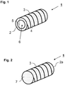
- Fig. 1 shows a graphical representation of an embodiment of a heating element 1 according to the invention, in which the carrier material 2 is tubular.
- the heating conductor structures 3 are located on the outer surface 4 of the tube 2 and are arranged spirally.
- the glass tube 2 has a diameter 5 of less than 20 mm, the wall thickness of the tube is less than 5 mm.
- the heating element 1 is suitable, for example, for use as an externally fitting, cylindrical heating element for so-called. Heat-not-burn cigarettes.
- the in Fig. 1 shown construction of the heating element 1 can also be realized with an ultrathin glass as a carrier material.
- a corresponding ultrathin glass for example an alkali aluminosilicate glass, can initially be provided as flat glass.
- the glass can be provided with heat conductor structures 3 and rolled up into a tube.
- the substrate 2a is in the form of a Glass or glass ceramic rod formed with a diameter smaller than 20 mm.
- the heating conductor structures 3 are applied as a spiral coating on the surface of the carrier material 2a.
- the ends 7 of the substrate 2a are formed flat in the embodiment shown here.
- the substrate 2a may also have round or pointed ends depending on the requirement for the design of the heating element. A different geometric configuration of the two ends of the substrate 2a is possible.
- Fig. 3 shows a graphical representation of another embodiment in which the substrate 2 c is formed as a flat glass and meander-shaped Bankleiter Modellen 3 has.
- the carrier material is in this case formed at one end to a tip. This makes it possible, for example, in Fig. 3 To introduce heating elements shown in a tobacco piece.
- the heating conductor structures 3 can be connected via the contacts 8a and 8b to a power source (not shown).
- a power source not shown
- the Fig. 3 embodiment shown can be realized with ultrathin flat glass as a substrate 2c.
- glass thicknesses of less than 100 microns or even less than 50 microns are possible.
- Fig. 4 shows a graphical representation of another embodiment in which the substrate 2d is formed as a flat glass and full-surface heating conductor structures 3 has.
- the carrier material is in this case formed at one end to a tip. This allows for example in the Fig. 4 To introduce heating elements shown in a tobacco piece.
- the cigarette 9 comprises a tip 10 and a mouthpiece 19 on which the user draws to inhale the aerosol generated in the cigarette by means of an evaporator 15.
- the mouthpiece 19 is detachable from the tip 10.
- the cigarette 9 includes an electrical energy storage 12 to provide the electrical energy for vaporization of the organic liquid in the evaporator 12.
- the electrical energy storage 12 is housed in the top 10 of the cigarette 9.
- the electronic cigarette 9 further includes a control unit 13 which controls the heating power of the heating element in the evaporator 15.
- the control unit 13 may be configured to determine whether a user inhales and, depending thereon, regulates the heating power of the heating element 16.
- a light-emitting diode 11 may further be arranged, which is also controlled by the control unit 13. If the control unit 13 registers that the user pulls on the cigarette 9, it can control the light-emitting diode 11 so that the light-emitting diode 11 lights up. This will produce an optical effect according to the Glowing when pulled on a conventional cigarette.
- the evaporator unit 15 comprises a liquid reservoir 17 and an organic carrier liquid 18 received therein.
- the evaporator unit 15 comprises the electrically heatable heating element 16 for heating the liquid reservoir 17 and thus evaporating the organic carrier liquid 18 with components dissolved therein, such as nicotine, fragrances and / or flavorings
- the heating element 16 is supplied with power via the control unit 13 controlled by the electrical energy store 12.
- the liquid storage recorded organic carrier liquid 18, in particular a high-boiling alcohol, such as glycerol or propylene glycol can be evaporated.
Landscapes
- Chemical & Material Sciences (AREA)
- Engineering & Computer Science (AREA)
- Ceramic Engineering (AREA)
- Glass Compositions (AREA)
- Resistance Heating (AREA)
- Joining Of Glass To Other Materials (AREA)
Abstract
Description
- Die Erfindung betrifft im Allgemeinen ein Heizelement für Heißanwendungen. Im Speziellen betrifft die Erfindung ein Heizelement zur geregelten Erwärmung und Verdampfung von verdampfbaren und/oder tabakhaltigen Substanzen in elektronischen Zigaretten.
- Elektronische Zigaretten, im Folgenden auch als E-Zigaretten bezeichnet, finden im zunehmenden Maße als Alternative zu Tabakzigaretten Verwendung. Typischerweise weisen E-Zigaretten hierbei ein Mundstück sowie eine Verdampfereinheit umfassend ein Heizelement auf.
- Das Heizelement erhitzt hierbei eine verdampfbare Flüssigkeit, so dass diese vom Anwender inhaliert werden kann. Diese Flüssigkeit kann bereits Nikotin enthalten. Alternativ ist die Flüssigkeit nikotinlos. Hierbei kann das sich bildende Aerosol dann einen nikotinhaltigen und nikotinlässigen Körper durchfluten.
- So sind aus dem Stand der Technik beispielsweise lanzenförmige Heizelemente bekannt. Diese werden in ein speziell designtes Tabakstück gesteckt und somit in Kontakt mit den zu verdampfenden Substanzen gebracht und heizen diese auf Temperaturen im Bereich von 50°C bis 350°C auf. Hierdurch kommt es zu einer Aerosolbildung. Entsprechende Heizlanzen können dabei aus einem Heizdraht ohne Trägermaterial bestehen. Nachteilig ist hierbei jedoch, dass auf Grund der benötigten mechanischen Stabilität des Heizelements die Abmessungen des Heizelements nicht beliebig klein gestaltet werden können. Des Weiteren verschmutzen entsprechende Heizelemente bei der Benutzung leicht.
- Im Stand der Technik werden daher alternativ Heizlanzen beschrieben, deren Heizleiterstrukturen auf einem Trägermaterial aufgebracht sind. Diese Heizlanzen weisen keramische Trägermaterialien auf, da diese neben einer hohen Temperaturstabilität eine elektrische Isolierung aufweisen. So werden in der
EP 2 469 969 Heizlanzen mit Trägermaterialien auf der Basis von ZrO2-Keramiken beschrieben. - Nachteilig bei der Verwendung von keramischen Trägermaterialien ist jedoch neben den hohen Herstellungskosten deren hohe Oberflächenrauhigkeit sowie Porosität. Rauheit und Porosität wirken sich hierbei nachteilig auf die in Form einer leitfähigen Beschichtung aufgebrachten Heizleiterstrukturen auf. So wirkt sich die die raue Oberfläche nachteilig auf die Anhaftung der leitfähigen Beschichtung auf dem Trägermaterial aus.
- Des Weiteren weisen die bekannten keramischen Trägermaterialien eine hohe Wärmeleitfähigkeit auf. Dies ist für die Verwendung in einem Heizelement nachteilig, da somit die im Heizbereich des Heizelements erzeugte Wärme nicht gezielt an das zu erhitzende Medium abgegeben werden kann, sondern eine Wärmeableitung durch die Keramik erfolgt und die so abgeleitete Wärme somit nicht mehr für die Verdampfung bzw. Erwärmung der Substanzen zur Verfügung steht. Entsprechend muss mehr Heizleistung durch das Heizelement aufgebracht werden, was sich nicht nur nachteilig auf den Energieverbrauch und somit beispielsweise auf die Batterie- bzw. Akkulaufzeit der E-Zigarette auswirkt, sondern auch zu einer Temperaturerhöhung innerhalb der E-Zigarette führen und sich somit nachteilig auf die Lebensdauer des Heizelements auswirken kann.
- In einem alternativen Aufbau einer E-Zigarette kann das Heizelement innerhalb der E-Zigarette auch so angeordnet werden, dass dieses nicht direkt in das Tabakstück bzw. die zu verdampfenden Substanzen eingebracht werden, sondern das Tabakstück bzw. ein Reservoir mit den zu verdampfenden Substanzen zylinderförmig umschließen. Eine entsprechende Anordnung wird beispielsweise in der
US 2005/0172976 beschrieben. Derartige externe Heizelemente bieten den Vorteil, dass die zu verdampfenden Substanzen bzw. Tabakstücke einfacher ausgetauscht werden können.
Auf Grund der gewünschten geringen Abmessungen der E-Zigaretten, die typischerweise den Abmessungen konventioneller Tabakzigaretten nachempfunden werden, ergeben sich bei einer derartigen Anordnung des Heizelements sehr geringe Durchmesser und somit Biegeradien. Da es sich bei dem Trägermaterial zudem um einen elektrischen Isolator handeln muss, werden bislang als Trägermaterial nur Hochleistungskunststoffe wie beispielsweise Polyimide oder Polyamide verwendet. - Bei diesen Anordnungen werden Leistungsfähigkeit sowie Lebensdauer des Heizelements durch die relativ geringe Temperaturbeständigkeit der Kunststoffe limitiert. Zudem kann es durch die in der E-Zigarette verwendeten organischen Lösungsmitteln zu Auslaugungseffekten kommen. Dies ist zum einen in Hinblick auf die Lebensdauer des Heizelementes nachteilig. Zudem können so Bestandteile des Trägermaterials im organischen Lösungsmittel gelöst und vom Anwender inhaliert werden.
- Eine Aufgabe der Erfindung besteht daher darin, ein Heizelement, insbesondere zur Verwendung in E-Zigaretten, bereit zu stellen, welches neben einer hohen Heizperformance und einer hohen Lebensdauer auch in einer Vielzahl von E-Zigaretten mit unterschiedlichen Aufbauten eingesetzt werden kann.
- Die Aufgabe der Erfindung wird bereits durch den Gegenstand der unabhängigen Ansprüche gelöst. Vorteilhafte Ausführungsformen und Weiterbildungen sind Gegenstand der Unteransprüche.
- Das erfindungsgemäße Heizelement ist insbesondere zur Verwendung in einer E-Zigarette geeignet und umfasst zumindest ein Trägermaterial aus Glas oder Glaskeramik und metallische Heizleiterstrukturen.
- Das Trägermaterial aus Glas oder Glaskeramik weist hierbei eine hohe Temperaturstabilität von mehr als 300°C oder sogar mehr als 400°C auf. Dies wird beispielsweise bei der Verwendung von Gläsern mit einer hohen Glasübergangstemperatur Tg erreicht.
- Gleichzeitig weist das Trägermaterial eine sehr geringe thermische Leitfähigkeit von < 2 W/(K*m). Die geringe thermische Leitfähigkeit sowie die geringe Wärmekapazität des Trägermaterials verringern bzw. verhindern hierbei die Ausbreitung der vom Heizelement erzeugten Wärme im Trägermaterial und ermöglichen so eine gezielte Wärmeleitung vom Heizelement zu den zu verdampfenden Substanzen. Gemäß einer vorteilhaften Ausführungsform der Erfindung weist das Trägermaterial eine Wärmeleitfähigkeit < 1, 8 W/ (K*m) oder sogar < 1,5 W/ (K*m) auf.
- Gleichzeitig beträgt die spezifische Wärmekapazität des Trägermaterials weniger als 1200 J/K*kg, bevorzugt sogar weniger als 1000 J/K*kg. Durch die geringe Wärmekapazität wird gewährleistet, dass die im Heizelement erzeugte Wärme schnell und möglichst vollständig zu den zu verdampfenden Substanzen geleitet wird. Dies ist in Hinblick auf den Energiebedarf beim Verdampfungsvorgang vorteilhaft. Gleichzeitig wird somit auch eine übermäßige Erwärmung des Heizelementes vermieden, was sich vorteilhaft auf dessen Lebensdauer auswirkt.
- Somit sind bevorzugt sowohl eine geringe Wärmeleitfähigkeit wie auch eine geringe Wärmekapazität des Trägermaterials notwendig, um eine gute Heizperformance des Heizelementes zu erreichen. Eine Weiterbildung der Erfindung sieht daher vor, dass das Heizelement eine FOM für das Produkt von Wärmeleitfähigkeit und Wärmekapazität

- Das Trägermaterial sorgt für die mechanische Stabilität des Heizelements. Auf der bzw. auf einer Oberfläche des Trägermaterials sind metallische Heizleiterstrukturen aufgebracht. Diese können beispielsweise in Form einer Beschichtung auf das Trägermaterial aufgebracht werden. Da das erfindungsgemäße Trägermaterial eine sehr glatte Oberfläche aufweist und die Rauheit Ra kleiner als 500 nm oder sogar kleiner als 250 nm, besonders bevorzugt sogar kleiner 20nm beträgt, kann zwischen Trägermaterial und metallischen Heizleiterstrukturen eine besonders gute Anhaftung erzielt werden. Dies äußert sich beispielsweise in einer hohen mechanischen Beständigkeit des Heizelements.
- Auf Grund der hohen mechanischen Festigkeit des verwendeten Trägermaterials kann dieses entsprechend dünn ausgebildet sein. Dies ermöglicht eine besonders kompakte Bauweise des Heizelementes sowie der gesamten E-Zigarette.
- Bei der Herstellung der erfindungsgemäßen Heizelemente kann das Glas (bzw. bei der Verwendung von Glaskeramiken als Trägermaterial das entsprechende Grünglas) durch Ziehprozesse in die gewünschte Form bzw. Geometrie gebracht werden. Dies ermöglicht neben einer flexiblen Anpassung des Trägermaterials an den jeweiligen Aufbau der E-Zigarette auch eine kostengünstige Herstellung der Heizelemente.
- Gemäß einer Ausführungsform der Erfindung ist das Trägermaterial als Rohr oder Stab mit einem Durchmesser < 20 mm ausgebildet. Das Rohr bzw. der Stab kann dabei einen runden, elipsoiden, drei- oder mehrwinkligen Querschnitt aufweisen. Das Trägermaterial kann auch in Form eines hohlen Glasprofils ausgebildet sein. Die entsprechenden Glasrohre bzw. -stäbe können durch Ziehprozesse erhalten werden. In einer Weiterbildung der Ausführungsform weisen die Glasrohre eine Wandstärke von weniger als 5 mm auf.
- Gemäß einer weiteren Ausführungsform der Erfindung ist das Glas des Trägermaterials als Dünn- oder Dünnstglas ausgebildet und weist eine Dicke von weniger als 2000 µm, weniger als 1000 µm oder sogar weniger als 500 µm auf. Das Trägermaterial kann hierbei als Flachglas ausgebildet sein.
- Sogar die Verwendung von Dünngläsern mit Dicken von weniger als 100 µm oder sogar weniger als 50 µm als Trägermaterial ist möglich.
- In einer Weiterbildung dieser Ausführungsform wird das Dünnglas dagegen in eine Glasrolle mit einem Durchmesser < 20 mm überführt. Dies kann beispielsweise durch ein Aufrollen des entsprechenden Flachglases erfolgen. Hierbei können auch Trägermaterialien in Form von Dünnglasrollen mit einem Durchmesser von weniger als 10 mm erhalten werden.
- Als für die Verwendung als Trägermaterial geeignete Gläser haben sich insbesondere Silikatgläser, Borosilikatgläser, Aluminiumsilikatgläser oder Aluminiumborosilikatgläser herausgestellt. Auch daraus über Temperaturbehandlung entwickelte Glaskeramiken sind einsetzbar.
- Gemäß einer Ausführungsform der Erfindung handelt es sich bei dem Trägermaterial um ein Glas mit folgenden Bestandteilen (in Gew%):
SiO2 50 bis 66 B2O3 0 bis 7 Al2O3 10 bis 25 MgO 0 bis 7 CaO 5 bis 16 SrO 0 bis 8 BaO 6 bis 18 P2O3 0 bis 2 ZrO2 0 bis 3 TiO2 0 bis 5. - Als besonders vorteilhaft haben sich hierbei Gläser mit folgenden Bestandteilen (in Gew%)herausgestellt:
SiO2 52 bis 64 B2O3 0 bis 5,5 Al2O3 12 bis 18 MgO 0 bis 5 CaO 9 bis 14,5 SrO 0 bis 4 BaO 8 bis 12 P2O3 0 bis 1 ZrO2 0 bis 2 TiO2 0 bis 3 - Als Silikatgläser können auch Borosilikatgläser wie Zn-Ti-Borosilikatgläser, Zn-Silikatgläser oder auch Natriumsilikatgläser mit einem hohen SiO2-Gehalt verwendet werden.
- Eine weitere Ausführungsform der Erfindung sieht vor, dass alkalihaltige Borosilikatgläser mit folgenden Bestandteilen (in Gew%-%) als Trägerglas verwendet werden:
SiO2 70 bis 85 B2O3 0 bis 15 Al2O3 1 bis 10 Na2O 1 bis 10 K2O 0 bis 5 CaO 0 bis 5, bevorzugt ≥ 0,1. - In einer weiteren Ausführungsform der Erfindung enthält das Glas folgende Bestandteile (Angaben in mol-%):
SiO2 64 bis 78 Al2O3 5 bis 14 Na2O 4 bis 12 K2O 0 bis 5 MgO 0 bis 14 CaO 1 bis 12 ZrO2 0 bis 2 TiO2 0 bis 4,5 - Al2O3/Na2O ≥ 1 mol-% und
- ∑SiO2 + Al2O3 ≤ 82 mol-%
- In einer weiteren Ausführungsform der Erfindung enthält das Glas folgende Bestandteile (Angaben in Gew%):
SiO2 58 bis 65 B2O3 6 bis 10,5 Al2O3 14 bis 25 MgO 0 bis 5 CaO 0 bis 9 BaO 0 bis 8, bevorzugt 3-8 SrO 0 bis 8 ZnO 0 bis 2 - In einer weiteren Ausführungsform der Erfindung enthält das Glas folgende Bestandteile (Angaben in Gew%):
SiO2 50 bis 65 Al2O3 15 bis 20 B2O3 0 bis 6 Li2O 0 bis 6 Na2O 8 bis 15 K2O 0 bis 5 MgO 0 bis 5 CaO 0 bis 7, bevorzugt 0 bis 1 ZnO 0 bis 4, bevorzugt 0 bis 1 ZrO2 0 bis 4 TiO2 0 bis 1, bevorzugt im wesentlichen TiO2-frei - In einer weiteren Ausführungsform der Erfindung enthält das Glas folgende Bestandteile (Angaben in Gew%):
SiO2 30 bis 85 B2O3 3 bis 20 Al2O3 0 bis 15 Na2O 3 bis 15 K2O 3 bis 15 ZnO 0 bis 12 TiO2 0,5 bis 10 CaO 0 bis 0,1 - In einer weiteren Ausführungsform der Erfindung enthält das Glas folgende Bestandteile (Angaben in Gew%):
SiO2 55 bis 75 Na2O 0 bis 15 K2O 2 bis 14 Al2O3 0 bis 15 MgO 0 bis 4 CaO 3 bis 12 BaO 0 bis 15 ZnO 0 bis 5 TiO2 0 bis 2 - In einer weiteren Ausführungsform der Erfindung enthält das Glas folgende Bestandteile (Angaben in Gew%):
SiO2 50 bis 70 Na2O 0 bis 5 K2O 0 bis 5 Al2O3 17 bis 27 MgO 0 bis 5 BaO 0 bis 5 SrO 0 bis 5 ZnO 0 bis 5 TiO2 0 bis 5 ZrO2 0 bis 5 Ta2O5 0 bis 8 P2O5 0 bis 10 Fe2O3 0 bis 5 CeO2 0 bis 5 Bi2O3 0 bis 3 WO3 0 bis 3 MoO3 0 bis 3 - Sowie übliche Läutermittel z.B. SnO2, SO4, Cl, AS2O3, Sb2O3 in Mengen von 0 bis 4 Gew.-%
- In einer weiteren Ausführungsform der Erfindung enthält das Glas folgende Bestandteile (Angaben in Gew%):
SiO2 35 bis 70, bevorzugt 35 bis 60 Al2O3 14 bis 40, bevorzugt 16,5 bis 40 MgO 0 bis 20, bevorzugt 4 bis 20, besonders bevorzugt 6 bis 20 BaO 0 bis 10, bevorzugt 0 bis 8 SrO 0 bis 5, bevorzugt 0 bis 4 ZnO 0 bis 15, bevorzugt 0 bis 9, besonders bevorzugt 0 bis 4 TiO2 0 bis 10, bevorzugt 1 bis 10 ZrO2 0 bis 10, bevorzugt 1 bis 10 Ta2O5 0 bis 8, bevorzugt 0 bis 2 B2O3 0 bis 10, bevorzugt > 4 bis 10 CaO 0 bis < 8, bevorzugt 0 bis 5, besonders bevorzugt < 0,1 P2O5 0 bis 10, bevorzugt < 4 Fe2O3 0 bis 5 CeO2 0 bis 5 Bi2O3 0 bis 3 WO3 0 bis 3 MoO3 0 bis 3 - Sowie übliche Läutermittel z.B. SnO2, SO4, Cl, AS2O3, Sb2O3 in Mengen von 0 bis 4 Gew.-%
- Insbesondere Alkalihaltige Aluminosilikate können hierbei durch Ionenaustausch chemisch gehärtet und die mechanische Stabilität des Trägermaterials kann so weiter erhöht werden. Insbesondere kann die Bruchwahrscheinlichkeit signifikant gesenkt werden. Auf Grund der hohen Glasübergangstemperatur Tg der Gläser von über 600°C kann hierbei der Ionenaustausch bei Temperaturen von über 400°C erfolgen, so dass nur eine geringe Ionenaustauschzeit benötigt wird. Eine Weiterbildung der Erfindung sieht daher vor, dass das Trägermaterial ein chemisch gehärtetes Glas ist.
- Dies ist insbesondere bei Trägermaterialien auf der Basis von Dünn- oder Dünnstgläsern besonders vorteilhaft. So können beispielsweise flache oder ultraflache Trägerkomponenten mit einer Dicke im Bereich von 0,1 bis 0,5 mm durch ein Down-Draw oder Overflow Fusion Verfahren erhalten und ohne vorherige weitere Dünnung chemisch gehärtet werden.
- Alternativ oder zusätzlich kann die mechanische Festigkeit der Trägerkomponente durch eine chemische und/oder mechanische Kantenbearbeitung wie beispielsweise. Kontourierung oder Kantenätzen weiter erhöht werden. Eine Weiterbildung der Erfindung sieht daher vor, dass die Kanten der Trägerkomponente chemisch und/oder mechanisch bearbeitet sind. Dies ist insbesondere bei Heizelementen mit Trägerkomponenten aus alkalifreien Gläsern vorteilhaft, da hier keine Erhöhung der mechanischen Festigkeit durch Ionenaustausch erfolgen kann. Der Einsatz von alkalifreien Gläsern, beispielsweise von alkalifreien Aluminoborosilikatgläsern als Trägermaterial ist hierbei auf Grund ihrer hohen chemischen Resistenz sowie der guten Verarbeitbarkeit, insbesondere der Möglichkeit, die entsprechenden Gläser in ultradünne Formen ziehen zu können, besonders vorteilhaft.
- Gemäß einer weiteren Ausführungsform der Erfindung wird als Trägerkomponente eine Glaskeramik, bevorzugt eine LAS-Glaskeramik (Lithiumaluminiumsilikat-Glaskeramik) oder MAS-Glaskeramik (Magnesiumaluminiumsilikat-Glaskeramik)verwendet. So weisen LAS-Glaskeramiken sehr niedrige thermische Leitfähigkeitswerte von 1,1 W/K*m auf, was sich vorteilhaft auf die Heizperformance auswirkt. Gleichzeitig weisen Glaskeramiken eine hohe mechanische Stabilität auf.
- Die Heizleiterstrukturen können beispielsweise spiralförmig oder meanderförmig auf der Oberfläche des Trägermaterials aufgebracht sein. Eine weitere Ausführungsform der Erfindung sieht eine vollflächige Aufbringung der Heizleiterstrukturen auf dem Trägermaterial vor.
- Bei einem rohrförmigen Trägermaterial können je nach Ausgestaltung des Heizelements bzw. der entsprechenden E-Zigarette die Heizleiterstrukturen auf der inneren oder der äußeren Mantelfläche des Trägermaterials aufgebracht sein.
- Gemäß einer Ausführungsform der Erfindung sind die Heizleiterstrukturen in Form einer elektrisch leitenden Beschichtung, bevorzugt als platinhaltige Beschichtung oder ITO-Beschichtung auf die Oberfläche des Trägermaterials aufgebracht.
- Nachfolgend wird die Erfindung an Hand von Ausführungsbeispielen sowie der
Figuren 1 bis 5 näher erläutert. Es zeigen: -
Fig. 1 eine graphische Darstellung eines Ausführungsbeispiels eines erfindungsgemäßen Heizelements, bei welchem das Trägermaterial rohrförmig ausgebildet ist und sich die Heizleiterstrukturen auf der äußeren Mantelfläche des Rohrs befinden, -
Fig. 2 eine graphische Darstellung eines Ausführungsbeispiels eines erfindungsgemäßen Heizelements, bei welchem das Trägermaterial stabförmig ausgebildet ist -
Fig. 3 eine graphische Darstellung eines weiteren Ausführungsbeispiels, bei welchem das Trägermaterial als Flachglas ausgebildet ist und meanderförmige Heizleiterstrukturen aufweist, -
Fig. 4 eine graphische Darstellung eines weiteren Ausführungsbeispiels, bei welchem das Trägermaterial als Flachglas ausgebildet ist und vollflächige Heizleiterstrukturen aufweist und - Fig. 5 den schematischen Aufbau einer elektronischen Zigarette.
- Die Tabellen 1 bis 4 zeigen 13 verschiedene Ausführungsbeispiele für das verwendete Trägermaterial. Die einzelnen Ausführungsbeispiele unterscheiden sich hierbei hinsichtlich der Zusammensetzung des Glases. Die in Tabelle 1 aufgeführten Beispiele 1 bis 5 enthalten Alkaliionen und können chemisch gehärtet werden, bei den in Tabelle 2 aufgeführten Beispielen 6 und 7 handelt es sich um Alkalifreie Gläser. Hier kann beispielsweise eine weitere Erhöhung der mechanischen Festigkeit durch eine chemische und/oder mechanische Kantenbearbeitung erfolgen.
Tabelle 1: Alkalihaltige Ausführungsbeispiele Bestandteil Beispiel 1 Gew% Beispiel 2 Gew% Beispiel 3 Gew.% Beispiel 4 Mol% Beispiel 5 Mol% SiO2 81 79 75 68,5 68,2 B2O3 12,7 10 10 Al2O3 2,4 4 6 12 11,8 Na2O 3,5 5 7 12 10,5 K2O 0,6 1 0 0, 5 0 MgO 1,2 CaO 0 1 1,5 5 5,2 TiO2 1,5 3,1 ZurO2 0,5 0 α20-300 [ppm/K] 3,3*10-6 4*10-6 4, 9*10-6 7,6*10-6 6,8*10-6 Tg [°C] 525 555 565 642 685 Dichte [g/cm3] 2,2 2,3 2,34 2,46 2,47 Thermische Leitfähigke it @ 90°C [W m-1 K-1] 1,3 1,1 1,2 1,0 1,0 Mittlere spezifische Wärmekapazi tät Cp bei 20-100°C [J/ (K*g)] 0,82 Tabelle 2: Alkalifreie Ausführungsbeispiele Bestandteil Beispiel 6 Gew.% Beispiel 7 Gew% SiO2 60 61 B2O3 4, 5 0,5 Al2O3 14 16,2 MgO 2,5 CaO 10 13 BaO 9 8 ZrO2 1 α20-300 [ppm/K] 4,6*10-6 4,7*10-6 Tg [°C] 720 790 Dichte [g/cm3] 2,63 2,67 Thermische Leitfähigke it @ 90°C [W m-1 K-1] 1,1 1,1 Tabelle 3: Ausführungsbeispiele 8 bis 11 Bestandteil Beispiel 8 Gew% Beispiel 9 Gew% Beispiel 10 Gew.% Beispiel 11 Gew.% SiO2 61 60,7 64,0 64 - 74 B2O3 10 8,3 Al2O3 18 16,9 4,0 Na2O 12,2 6,5 6 - 10 K2O 4,1 7,0 6 - 10 MgO 2,8 3,9 CaO 4,8 5 - 9 BaO 3,3 0 - 4 ZrO2 1,5 SnO2 0,4 CeO2 0,3 ZnO 5,5 2 - 6 TiO2 4,0 0 - 2 Sb2O3 0, 6 Cl 0,1 α20-300 [ppm/K] 3,2·10-6 7,2·10-6 9,4·10-6 Tg [°C] 717 557 553 Dichte [g/cm3] 2,43 2,5 2,55 Thermische Leitfähigke it @ 90°C [W m-1 K-1] 1,16 Mittlere spezifische Wärmekapazi tät Cp bei 20-100°C [J/ (K*g)] 0,8 Tabelle 4: Beispielhafte alkalihaltige Glaskeramikzusammensetzungen Bestandteil Beispiel 12 Gew.% Beispiel 13 Gew% SiO2 65,45 64,45 Al2O3 21,97 21,97 Na2O 0,51 0,51 Li2O 3,72 3,72 MgO 0,47 0,47 BaO 2,02 2,02 ZnO 1,7 1,7 TiO2 2,39 3,4 ZrO2 1,76 1,76 α20-300 [ppm/K] 4,0*10-6 4,05*10-6 Tg [°C] 690 685 Thermische Leitfähigke it @ 90°C [W m-1 K-1] 1,1 1,1 Mittlere spezifische Wärmekapazi tät Cp bei 20-100°C [J/ (K*g)] 0,80 0,81 - Tabelle 4 zeigt beispielhafte Ausgangsglas-Zusammensetzungen aus dem LAS Glaskeramiksystem. In keramisiertem Zustand liegen die Ausdehnungskoeffizienten im Bereich von 0 +/- 0,5 ppm/K. Die thermische Leitfähigkeit liegt bei 1,7 W m-1 K-1
-
Fig. 1 zeigt eine graphische Darstellung eines Ausführungsbeispiels eines erfindungsgemäßen Heizelements 1, bei welchem das Trägermaterial 2 rohrförmig ausgebildet ist. In diesem Ausführungsbeispiel befinden sich die Heizleiterstrukturen 3 auf der äußeren Mantelfläche 4 des Rohrs 2 und sind spiralförmig angeordnet. Das Glasrohr 2 weist einen Durchmesser 5 von weniger als 20 mm auf, die Wandstärke des Rohrs beträgt weniger als 5 mm. Durch den Hohlraum 6 ist das Heizelement 1 beispielsweise zur Verwendung als ein von außen anliegendes, zylindrisches Heizelement für sog. Heat-not-Burn-Zigaretten geeignet. - Der in
Fig. 1 dargestellte Aufbau des Heizelements 1 kann auch mit einem Ultradünnglas als Trägermaterial realisiert werden. So kann ein entsprechendes Ultradünnglas, beispielsweise ein Alkalialuminosilikatglas, zunächst als Flachglas bereitgestellt werden. In einem nachfolgenden Herstellungsschritt kann das Glas mit Heizleiterstrukturen 3 versehen und zu einem Rohr aufgerollt werden. - In
Fig. 2 wird eine weitere Ausführungsform des Heizelements 1 schematisch dargestellt. Gemäß dieser Ausführungsform ist das Trägermaterial 2a in Form eines Glas- oder Glaskeramikstabes mit einem Durchmesser kleiner 20 mm ausgebildet. Die Heizleiterstrukturen 3 sind als spiralförmige Beschichtung auf der Oberfläche des Trägermaterials 2a aufgebracht. Die Enden 7 des Trägermaterials 2a sind in der hier dargestellten Ausführungsform flach ausgebildet. Das Trägermaterial 2a kann jedoch abhängig von der Anforderung an das Design des Heizelementes auch runde oder spitze Enden aufweisen. Auch eine unterschiedliche geometrische Ausgestaltung der beiden Enden des Trägermaterials 2a ist möglich. -
Fig. 3 zeigt eine graphische Darstellung eines weiteren Ausführungsbeispiels, bei welchem das Trägermaterial 2c als Flachglas ausgebildet ist und meanderförmige Heizleiterstrukturen 3 aufweist. Das Trägermaterial ist hierbei an einem Ende zu einer Spitze ausgebildet. Dies ermöglicht es beispielsweise das inFig. 3 gezeigte Heizelemente in ein Tabakstück einzuführen. - Die Heizleiterstrukturen 3 können über die Kontakte 8a und 8b mit einer Energiequelle (nicht dargestellt) verbunden werden. Die in
Fig. 3 dargestellte Ausführungsform kann auch mit ultradünnen Flachgläsern als Trägermaterial 2c realisiert werden. Hierbei sind Glasdicken von weniger als 100 µm oder sogar weniger als 50 µm möglich. -
Fig. 4 zeigt eine graphische Darstellung eines weiteren Ausführungsbeispiels, bei welchem das Trägermaterial 2d als Flachglas ausgebildet ist und vollflächige Heizleiterstrukturen 3 aufweist. Das Trägermaterial ist hierbei an einem Ende zu einer Spitze ausgebildet. Dies ermöglicht es beispielsweise das inFig. 4 gezeigte Heizelemente in ein Tabakstück einzuführen. - In Fig. 5 ist eine elektronische Zigarette 9 dargestellt. Die Zigarette 9 umfasst eine Spitze 10 und ein Mundstück 19, an welchem der Benutzer zieht, um das in der Zigarette mittels eines Verdampfers 15 erzeugte Aerosol zu inhalieren. Gemäß einer bevorzugten Ausführungsform der Erfindung ist das Mundstück 19 von der Spitze 10 abnehmbar.
- Die Zigarette 9 enthält einen elektrischen Energiespeicher 12, um die elektrische Energie zur Verdampfung der organischen Flüssigkeit im Verdampfer 12 bereitzustellen. Bei der dargestellten Ausführungsform ist der elektrische Energiespeicher 12 in der Spitze 10 der Zigarette 9 untergebracht.
- Die elektronische Zigarette 9 enthält weiterhin eine Steuereinheit 13, welche die Heizleistung des Heizelements im Verdampfer 15 regelt. Insbesondere kann die Steuereinheit 13 eingerichtet sein, festzustellen, ob ein Benutzer inhaliert und abhängig davon die Heizleistung des Heizelements 16 zu regeln.
- In der Spitze 10 kann weiterhin eine Leuchtdiode 11 angeordnet sein, die ebenfalls von der Steuereinheit 13 angesteuert wird. Registriert die Steuereinheit 13, dass der Benutzer an der Zigarette 9 zieht, kann diese die Leuchtdiode 11 ansteuern, so dass die Leuchtdiode 11 leuchtet. Damit wird ein optischer Effekt entsprechend dem Aufglimmen beim Ziehen an einer herkömmlichen Zigarette erzielt.
- Die Verdampfereinheit 15 umfasst einen Flüssigkeitsspeicher 17 und eine darin aufgenommene organischer Trägerflüssigkeit 18. Zur Beheizung des Flüssigkeitsspeichers 17 und damit zur Verdampfung der organischen Trägerflüssigkeit 18 mit darin gelösten Bestandteilen, wie Nikotin, Duftstoffen und/oder Aromastoffen umfasst die Verdampfereinheit 15 das elektrisch beheizbares Heizelement 16. Das Heizelement 16 wird über die Steuereinheit 13 gesteuert vom elektrischen Energiespeicher 12 mit Strom versorgt. Durch Beheizen auf eine Betriebstemperatur größer als 100° C ist die Flüssigkeitsspeicher aufgenommene organische Trägerflüssigkeit 18, insbesondere ein hochsiedender Alkohol, wie Glycerin oder Propylenglykol verdampfbar.
Claims (22)
- Heizelement, insbesondere geeignet zur Verwendung in einer elektronischen Zigarette, umfassend zumindest ein Trägermaterial aus Glas oder Glaskeramik und metallische Heizleiterstrukturen, wobei die Heizleiterstrukturen auf dem Trägermaterial aufgebracht sind und das Trägermaterial eine thermische Leitfähigkeit < 2 W/K*m, eine Wärmekapazität < 1000 J/K*kg und eine Rauheit Ra < 500 nm aufweist.
- Heizelement gemäß dem vorstehenden Anspruch, wobei die thermische Leitfähigkeit des Trägermaterials < 1,8 W/K*m, bevorzugt < 1,5 W/K*m ist.
- Heizelement gemäß einem der vorstehenden Ansprüche, wobei das Trägermaterial rohr- oder stabförmig ausgebildet ist und bevorzugt einen Durchmesser < 20 mm und/oder einer Wandstärke < 5 mm aufweist.
- Heizelement gemäß dem vorherigen Anspruch, wobei das Trägermaterial als ein Glasrohr mit einem drei- oder mehreckigem Querschnitt ausgebildet ist.
- Heizelement gemäß einem der Ansprüche 1 bis 3, wobei das Trägermaterial als ein Glasrohr mit einem runden oder elipsoiden Querschnitt oder als hohles Glasprofil ausgebildet ist.
- Heizelement gemäß einem der vorstehenden Ansprüche, wobei das Trägermaterial aus einem Dünnglas, bevorzugt aus einem Dünnglas mit einer Dicke < 2000µm, bevorzugt < 1000µm, besonders bevorzugt <= 500µm gebildet wird.
- Heizelement gemäß einem der vorstehenden Ansprüche, wobei das Trägermaterial aus einem Dünnglas, bevorzugt aus einem Dünnglas mit einer Dicke, < 100 µm, bevorzugt < 50 µm gebildet wird.
- Heizelement gemäß dem vorstehenden Anspruch, wobei das Dünnglas zu einer Rolle mit einem Durchmesser < 20 mm, bevorzugt < 10 mm aufgerollt oder aufrollbar ist.
- Heizelement gemäß einem der vorstehenden Ansprüche, wobei das Trägermaterial ein Silikatglas, ein Borosilikatglas, ein Aluminiumsilikatglas oder ein Aluminiumborosilikatglas ist.
Al2O3 1 bis 10 Na2O 1 bis 10 K2O 0 bis 5 CaO 0 bis 5, bevorzugt ≥ 0,1. - Heizelement gemäß einem der vorstehenden Ansprüche 1 bis 9, wobei das Trägermaterial ein Glas mit den folgenden Bestandteilen (in Gew.-%)ist
- Heizelement gemäß einem der vorstehenden Ansprüche, wobei das Trägermaterial ein chemisch gehärtetes Glas ist.
- Heizelement gemäß dem vorstehenden Anspruch, wobei das Produkt von Wärmeleitfähigkeit und Wärmekapazität

- Heizelement gemäß einem der vorstehenden Ansprüche, wobei die Kanten des Dünnglases chemisch und/oder mechanisch bearbeitet sind.
- Heizelement gemäß einem der Ansprüche 1 bis 3, wobei das Trägermaterial eine Glaskeramik, bevorzugt eine LAS-Glaskeramik oder eine MAS-Glaskeramik ist.
- Heizelement gemäß einem der vorstehenden Ansprüche, wobei das Trägermaterial eine Rauheit kleiner 250 nm, bevorzug < 20 nm aufweist.
- Heizelement gemäß einem der vorstehenden Ansprüche, wobei die Heizleiterstrukturen als elektrisch leitende Beschichtung, bevorzugt als eine platinhaltige Beschichtung oder eine ITO-basierte Beschichtung ausgebildet ist.
- Heizelement gemäß einem der vorstehenden Ansprüche, wobei die Heizleiterstrukturen spiral- oder meanderförmig auf der Oberfläche des Trägermaterials angeordnet sind.
- Heizelement gemäß einem der vorstehenden Ansprüche 1 bis 16, wobei die Heizleiterstrukturen vollflächig auf der Oberfläche des Trägermaterials angeordnet sind.
- Heizelement gemäß einem der vorstehenden Ansprüche, wobei die Heizleiterstrukturen auf der äußeren Mantelfläche des Trägermaterials angeordnet sind.
- Heizelement gemäß einem der vorstehenden Ansprüche 1 bis 18, wobei das Trägermaterial rohrförmig ausgebildet ist und die Heizleiterstrukturen auf der inneren Mantelfläche des Trägermaterials angeordnet sind.
- Heizelement gemäß einem der vorherigen Ansprüche 1 bis 18, wobei das Trägermaterial als Flachglas ausgebildet ist.
- Verwendung eines Heizelementes gemäß einem der vorherigen Ansprüche in einer elektronischen Zigarette.
Applications Claiming Priority (1)
| Application Number | Priority Date | Filing Date | Title |
|---|---|---|---|
| DE102016115574.8A DE102016115574B4 (de) | 2016-08-23 | 2016-08-23 | Heizelemente für elektronische Zigaretten |
Publications (3)
| Publication Number | Publication Date |
|---|---|
| EP3287021A2 true EP3287021A2 (de) | 2018-02-28 |
| EP3287021A3 EP3287021A3 (de) | 2018-03-14 |
| EP3287021B1 EP3287021B1 (de) | 2020-09-09 |
Family
ID=59409267
Family Applications (1)
| Application Number | Title | Priority Date | Filing Date |
|---|---|---|---|
| EP17183310.6A Active EP3287021B1 (de) | 2016-08-23 | 2017-07-26 | Heizelemente für elektronische zigaretten |
Country Status (5)
| Country | Link |
|---|---|
| US (1) | US10321719B2 (de) |
| EP (1) | EP3287021B1 (de) |
| JP (1) | JP6979829B2 (de) |
| DE (1) | DE102016115574B4 (de) |
| ES (1) | ES2822002T3 (de) |
Cited By (4)
| Publication number | Priority date | Publication date | Assignee | Title |
|---|---|---|---|---|
| CN110845251A (zh) * | 2019-11-05 | 2020-02-28 | 深圳顺络电子股份有限公司 | 一种雾化芯的制备方法、雾化芯、雾化组件及电子烟 |
| CN113149697A (zh) * | 2021-04-23 | 2021-07-23 | 深圳市基克纳科技有限公司 | 一种组合物及含连续玻璃相的多孔陶瓷雾化芯 |
| CN113316400A (zh) * | 2019-01-15 | 2021-08-27 | 热特龙 | 热传递效率优秀的卷烟型电子烟用加热器及其制造方法 |
| WO2022241931A1 (zh) * | 2021-05-20 | 2022-11-24 | 惠州市沛格斯科技有限公司 | 加热模组及包括该加热模组的发烟装置 |
Families Citing this family (25)
| Publication number | Priority date | Publication date | Assignee | Title |
|---|---|---|---|---|
| KR102551450B1 (ko) * | 2017-08-09 | 2023-07-06 | 필립모리스 프로덕츠 에스.에이. | 서셉터 층을 갖는 에어로졸 발생 장치 |
| GB201722177D0 (en) * | 2017-12-28 | 2018-02-14 | British American Tobacco Investments Ltd | Heating element |
| GB201722183D0 (en) | 2017-12-28 | 2018-02-14 | British American Tobacco Investments Ltd | Apparatus for heating aerosolisable material |
| CN108835716A (zh) * | 2018-08-07 | 2018-11-20 | 湖北中烟工业有限责任公司 | 一种应用于低温卷烟的加热器及其制备方法 |
| CA3116624A1 (en) * | 2018-09-07 | 2020-03-12 | Puff Corporation | Portable vaporizing device, cartridge and methods |
| US11129417B2 (en) * | 2018-09-07 | 2021-09-28 | Puff Corporation | Portable vaporizing device, cartridge and methods |
| EP3626093B1 (de) | 2018-09-24 | 2024-07-03 | Yageo Nexensos GmbH | Heizelement für ein system zur bereitstellung eines inhalierbaren aerosols |
| ES2973721T3 (es) | 2018-10-12 | 2024-06-24 | Jt Int Sa | Dispositivo de generación de aerosol y cámara de calentamiento para el mismo |
| DE102019103987A1 (de) * | 2019-02-18 | 2020-08-20 | Hauni Maschinenbau Gmbh | Verdampfervorrichtung für einen Inhalator, Verbrauchseinheit, Inhalator und Herstellungsverfahren |
| DE102019103988A1 (de) * | 2019-02-18 | 2020-08-20 | Hauni Maschinenbau Gmbh | Verdampfervorrichtung für einen Inhalator, Verbrauchseinheit, Inhalator und Herstellungsverfahren |
| DE202019001693U1 (de) | 2019-04-15 | 2019-06-17 | Heraeus Nexensos Gmbh | Heizelement mit exzentrischer Durchgangsöffnung für ein System zur Bereitstellung eines inhalierbaren Aerosols |
| CN211910539U (zh) * | 2019-05-16 | 2020-11-13 | 厦门蜂涛陶瓷有限公司 | 非接触式电子烟加热器及其发烟制品承载组件 |
| UA128048C2 (uk) * | 2019-05-16 | 2024-03-20 | Ксіамен Фенгтао Керамікс Ко., Лтд | Нагрівач для вейпу з нагріванням повітря, керамічний нагрівач і спосіб його виготовлення |
| CN210329343U (zh) * | 2019-05-29 | 2020-04-17 | 常州市派腾电子技术服务有限公司 | 雾化件及电子烟 |
| CN110194662B (zh) * | 2019-06-05 | 2022-05-17 | 阿特麦哲(东莞)科技有限公司 | 雾化芯及其制备方法和电子烟 |
| CN112390625B (zh) | 2019-08-12 | 2021-12-28 | 深圳麦克韦尔科技有限公司 | 复合陶瓷件及其制备方法、雾化组件和电子烟 |
| CN110652042A (zh) * | 2019-09-12 | 2020-01-07 | 深圳麦克韦尔科技有限公司 | 电子烘烤烟具及其发热装置 |
| CN112841741B (zh) | 2019-11-27 | 2023-05-12 | 深圳市合元科技有限公司 | 加热器以及包含该加热器的烟具 |
| CN112841726B (zh) * | 2019-11-27 | 2025-12-02 | 深圳市合元科技有限公司 | 加热器以及包括该加热器的烟具 |
| CN110839965B (zh) * | 2019-12-12 | 2025-07-29 | 深圳博迪恒业科技有限公司 | 一种电子烟发热组件 |
| CN113080521A (zh) * | 2019-12-23 | 2021-07-09 | 深圳市合元科技有限公司 | 加热器以及包含该加热器的烟具 |
| WO2022160136A1 (zh) * | 2021-01-27 | 2022-08-04 | 深圳麦克韦尔科技有限公司 | 陶瓷基体及其制备方法、陶瓷发热体及电子雾化装置 |
| WO2023131338A1 (zh) * | 2022-01-10 | 2023-07-13 | 深圳市卓力能技术有限公司 | 一种发热体 |
| WO2023177838A1 (en) | 2022-03-18 | 2023-09-21 | Puff Corporation | System and method for filling of cartridges for portable vaporizing devices |
| WO2024119383A1 (zh) * | 2022-12-06 | 2024-06-13 | 深圳市高斯博电子科技有限公司 | 一种加热装置、雾化装置和电子烟 |
Citations (2)
| Publication number | Priority date | Publication date | Assignee | Title |
|---|---|---|---|---|
| US20050172976A1 (en) | 2002-10-31 | 2005-08-11 | Newman Deborah J. | Electrically heated cigarette including controlled-release flavoring |
| EP2469969A1 (de) | 2010-12-24 | 2012-06-27 | Philip Morris Products S.A. | Reduziertes keramisches Heizelement |
Family Cites Families (25)
| Publication number | Priority date | Publication date | Assignee | Title |
|---|---|---|---|---|
| US5878752A (en) * | 1996-11-25 | 1999-03-09 | Philip Morris Incorporated | Method and apparatus for using, cleaning, and maintaining electrical heat sources and lighters useful in smoking systems and other apparatuses |
| JP2003243129A (ja) * | 2002-02-15 | 2003-08-29 | Narasaki Sangyo Co Ltd | ロールヒータおよび該ヒータを用いた連続式平面材料表面加熱装置 |
| US7997280B2 (en) * | 2004-01-30 | 2011-08-16 | Joshua Rosenthal | Portable vaporizer |
| JP2007035505A (ja) * | 2005-07-28 | 2007-02-08 | Harison Toshiba Lighting Corp | ヒータ、加熱装置、画像処理装置 |
| US7999211B2 (en) * | 2006-09-01 | 2011-08-16 | Hewlett-Packard Development Company, L.P. | Heating element structure with isothermal and localized output |
| EP2316286A1 (de) * | 2009-10-29 | 2011-05-04 | Philip Morris Products S.A. | Elektrisch erhitztes Rauchsystem mit verbesserter Heizvorrichtung |
| AR089602A1 (es) | 2011-12-30 | 2014-09-03 | Philip Morris Products Sa | Articulo generador de aerosoles para usar con un dispositivo generador de aerosoles |
| DE102012212351A1 (de) * | 2012-07-13 | 2014-01-16 | E.G.O. Elektro-Gerätebau GmbH | Heizeinrichtung und Wasserführungseinrichtung |
| US8881737B2 (en) * | 2012-09-04 | 2014-11-11 | R.J. Reynolds Tobacco Company | Electronic smoking article comprising one or more microheaters |
| WO2014073545A1 (ja) * | 2012-11-06 | 2014-05-15 | 貞徳舎株式会社 | 電気ヒーター並びにこれを備えた加熱装置及び半導体製造装置 |
| UA114651C2 (uk) * | 2012-12-28 | 2017-07-10 | Філіп Морріс Продактс С.А. | Нагрівальний блок для системи, що генерує аерозоль |
| DE202013100606U1 (de) | 2013-02-11 | 2013-02-27 | Ewwk Ug | Elektronische Zigarette oder Pfeife |
| CA2907731A1 (en) * | 2013-03-22 | 2014-09-25 | Altria Client Services Llc | Electronic smoking article |
| CN103960782B (zh) * | 2013-09-29 | 2016-09-21 | 深圳麦克韦尔股份有限公司 | 电子烟 |
| US9861132B2 (en) * | 2013-12-31 | 2018-01-09 | Shenzhen First Union Technology Co., Ltd. | Atomizer and electronic cigarette having same |
| KR20240136452A (ko) * | 2014-07-11 | 2024-09-13 | 필립모리스 프로덕츠 에스.에이. | 액체 니코틴 공급원을 포함하는 에어로졸 형성 카트리지 |
| CN204317492U (zh) * | 2014-11-14 | 2015-05-13 | 深圳市合元科技有限公司 | 适用于液体基质的雾化装置及电子烟 |
| EP2921065A1 (de) | 2015-03-31 | 2015-09-23 | Philip Morris Products S.a.s. | Aufheizungs- und heizungsanordnung für ein aerosolerzeugungssystem |
| US20170055581A1 (en) * | 2015-08-31 | 2017-03-02 | British American Tobacco (Investments) Limited | Article for use with apparatus for heating smokable material |
| CN105433441A (zh) * | 2015-12-14 | 2016-03-30 | 深圳市合元科技有限公司 | 发热组件、雾化器及电子烟 |
| CN205358219U (zh) * | 2015-12-31 | 2016-07-06 | 深圳市合元科技有限公司 | 发热组件、包含该发热组件的雾化器和电子烟 |
| DE202016100917U1 (de) * | 2016-02-22 | 2016-03-09 | Türk & Hillinger GmbH | Luft- und/oder Aerosolerhitzer |
| CN105747278A (zh) * | 2016-04-21 | 2016-07-13 | 深圳市合元科技有限公司 | 烟油加热装置以及雾化单元、雾化器和电子烟 |
| WO2017207580A1 (en) * | 2016-05-31 | 2017-12-07 | Philip Morris Products S.A. | Aerosol generating article with heat diffuser |
| MX2018014310A (es) * | 2016-05-31 | 2019-02-25 | Philip Morris Products Sa | Sistema generador de aerosol que comprende un articulo generador de aerosol calentado. |
-
2016
- 2016-08-23 DE DE102016115574.8A patent/DE102016115574B4/de active Active
-
2017
- 2017-07-26 EP EP17183310.6A patent/EP3287021B1/de active Active
- 2017-07-26 ES ES17183310T patent/ES2822002T3/es active Active
- 2017-08-22 US US15/682,877 patent/US10321719B2/en active Active
- 2017-08-23 JP JP2017160162A patent/JP6979829B2/ja active Active
Patent Citations (2)
| Publication number | Priority date | Publication date | Assignee | Title |
|---|---|---|---|---|
| US20050172976A1 (en) | 2002-10-31 | 2005-08-11 | Newman Deborah J. | Electrically heated cigarette including controlled-release flavoring |
| EP2469969A1 (de) | 2010-12-24 | 2012-06-27 | Philip Morris Products S.A. | Reduziertes keramisches Heizelement |
Cited By (4)
| Publication number | Priority date | Publication date | Assignee | Title |
|---|---|---|---|---|
| CN113316400A (zh) * | 2019-01-15 | 2021-08-27 | 热特龙 | 热传递效率优秀的卷烟型电子烟用加热器及其制造方法 |
| CN110845251A (zh) * | 2019-11-05 | 2020-02-28 | 深圳顺络电子股份有限公司 | 一种雾化芯的制备方法、雾化芯、雾化组件及电子烟 |
| CN113149697A (zh) * | 2021-04-23 | 2021-07-23 | 深圳市基克纳科技有限公司 | 一种组合物及含连续玻璃相的多孔陶瓷雾化芯 |
| WO2022241931A1 (zh) * | 2021-05-20 | 2022-11-24 | 惠州市沛格斯科技有限公司 | 加热模组及包括该加热模组的发烟装置 |
Also Published As
| Publication number | Publication date |
|---|---|
| JP6979829B2 (ja) | 2021-12-15 |
| US20180064170A1 (en) | 2018-03-08 |
| JP2018032628A (ja) | 2018-03-01 |
| US10321719B2 (en) | 2019-06-18 |
| DE102016115574A1 (de) | 2018-04-05 |
| ES2822002T3 (es) | 2021-04-28 |
| DE102016115574B4 (de) | 2024-06-20 |
| EP3287021B1 (de) | 2020-09-09 |
| EP3287021A3 (de) | 2018-03-14 |
Similar Documents
| Publication | Publication Date | Title |
|---|---|---|
| EP3287021B1 (de) | Heizelemente für elektronische zigaretten | |
| DE102017123000B4 (de) | Sinterkörper mit leitfähiger Beschichtung, Verfahren zur Herstellung eines Sinterkörpers mit leitfähiger Beschichtung und dessen Verwendung | |
| DE112016002809B4 (de) | Offenporige Sintergläser zur Verwendung in elektronischen Zigaretten | |
| DE102008056323B4 (de) | Verwendung von alkalifreien Aluminoborosilikatgläsern für Leuchtmittel mit außen- oder innenliegender Kontaktierung | |
| AT207058B (de) | Verfahren zur Herstellung eines leitfähigen, nichtmetallischen Überzuges auf einem nichtleitenden Gegenstand | |
| DE2014232B2 (de) | Tonerde-Silikatglas, das zur Erzielung hoher mechanischer Festigkeit durch Alkalimetallionen-Austausch hohe Austauschtemperatur und damit große Diffusionsgeschwindigkeit ermöglicht | |
| EP0245734B1 (de) | Elektrische Lampe | |
| WO2022106612A1 (de) | Elektrisch leitfähiger, poröser sinterkörper mit zumindest zwei elektrisch leitfähigen materialien und verfahren zu dessen herstellung | |
| EP3124447A1 (de) | Bor-armes, zirkonium-freies neutralglas mit optimiertem alkaliverhältnis | |
| EP2562143A1 (de) | Borosilikatglaszusammensetzung für die Herstellung von Glasrohren und seine Verwendung für die Herstellung von Glasrohren und als Hüllrohr für Lampen | |
| WO2019081312A1 (de) | Vorrichtung und verfahren zur herstellung eines flachglases | |
| DE2047661A1 (de) | Isolator | |
| EP1268354B1 (de) | Glas und glaspulvermischung sowie deren verwendung zur herstellung einer glaskeramik | |
| WO2022106613A1 (de) | Elektrisch leitfähiger poröser sinterkörper | |
| DE1204738B (de) | Elektrischer Schichtwiderstand | |
| DE102013225061B4 (de) | Hochbrechendes optisches Glas | |
| AT165989B (de) | Elektrische Entladungslampe mit Anlaßstreifen | |
| DE1049063B (de) | Glaeser zum direkten Verschmelzen mit Metallen und Legierungen hoher thermischer Ausdehnung | |
| DE102005000664B4 (de) | Verfahren zur Einstellung der UV-Absorption von Gläsern und Glaskeramiken und Verwendung von Gläsern und Glaskeramiken | |
| AT148057B (de) | Trägheitsarmer Widerstand mit fallender Stromspannungskennlinie. | |
| DE678419C (de) | Vakuumdichter keramischer Koerper | |
| DE598325C (de) | Elektrische Quecksilberdampflampe oder -roehre mit aus Borosilikatglas bestehendem Roehrengefaess | |
| DE102019100261A1 (de) | Element aus Glas mit verminderter elektrostatischer Aufladung | |
| EP4470980A1 (de) | Temperatursensor mit fixiertropfen und runden poren (rohs) | |
| DE1496487C (de) | Verfahren zur Herstellung eines Glas Kristall Mischkorpers mit hoher mechanischer Festigkeit und relativ hohem Warmeausdeh nungskoeffizienten sowie hohem elektrischen Isolationswiderstand |
Legal Events
| Date | Code | Title | Description |
|---|---|---|---|
| PUAI | Public reference made under article 153(3) epc to a published international application that has entered the european phase |
Free format text: ORIGINAL CODE: 0009012 |
|
| STAA | Information on the status of an ep patent application or granted ep patent |
Free format text: STATUS: REQUEST FOR EXAMINATION WAS MADE |
|
| PUAL | Search report despatched |
Free format text: ORIGINAL CODE: 0009013 |
|
| 17P | Request for examination filed |
Effective date: 20170726 |
|
| AK | Designated contracting states |
Kind code of ref document: A2 Designated state(s): AL AT BE BG CH CY CZ DE DK EE ES FI FR GB GR HR HU IE IS IT LI LT LU LV MC MK MT NL NO PL PT RO RS SE SI SK SM TR |
|
| AX | Request for extension of the european patent |
Extension state: BA ME |
|
| AK | Designated contracting states |
Kind code of ref document: A3 Designated state(s): AL AT BE BG CH CY CZ DE DK EE ES FI FR GB GR HR HU IE IS IT LI LT LU LV MC MK MT NL NO PL PT RO RS SE SI SK SM TR |
|
| AX | Request for extension of the european patent |
Extension state: BA ME |
|
| RIC1 | Information provided on ipc code assigned before grant |
Ipc: H05B 3/26 20060101ALI20180207BHEP Ipc: H05B 3/46 20060101ALI20180207BHEP Ipc: A24F 47/00 20060101AFI20180207BHEP |
|
| RBV | Designated contracting states (corrected) |
Designated state(s): AL AT BE BG CH CY CZ DE DK EE ES FI FR GB GR HR HU IE IS IT LI LT LU LV MC MK MT NL NO PL PT RO RS SE SI SK SM TR |
|
| GRAP | Despatch of communication of intention to grant a patent |
Free format text: ORIGINAL CODE: EPIDOSNIGR1 |
|
| STAA | Information on the status of an ep patent application or granted ep patent |
Free format text: STATUS: GRANT OF PATENT IS INTENDED |
|
| RIC1 | Information provided on ipc code assigned before grant |
Ipc: H05B 3/46 20060101ALI20200131BHEP Ipc: H05B 3/26 20060101ALI20200131BHEP Ipc: A24F 47/00 20200101AFI20200131BHEP |
|
| INTG | Intention to grant announced |
Effective date: 20200225 |
|
| GRAJ | Information related to disapproval of communication of intention to grant by the applicant or resumption of examination proceedings by the epo deleted |
Free format text: ORIGINAL CODE: EPIDOSDIGR1 |
|
| STAA | Information on the status of an ep patent application or granted ep patent |
Free format text: STATUS: REQUEST FOR EXAMINATION WAS MADE |
|
| GRAP | Despatch of communication of intention to grant a patent |
Free format text: ORIGINAL CODE: EPIDOSNIGR1 |
|
| STAA | Information on the status of an ep patent application or granted ep patent |
Free format text: STATUS: GRANT OF PATENT IS INTENDED |
|
| INTC | Intention to grant announced (deleted) | ||
| INTG | Intention to grant announced |
Effective date: 20200608 |
|
| GRAS | Grant fee paid |
Free format text: ORIGINAL CODE: EPIDOSNIGR3 |
|
| GRAA | (expected) grant |
Free format text: ORIGINAL CODE: 0009210 |
|
| STAA | Information on the status of an ep patent application or granted ep patent |
Free format text: STATUS: THE PATENT HAS BEEN GRANTED |
|
| AK | Designated contracting states |
Kind code of ref document: B1 Designated state(s): AL AT BE BG CH CY CZ DE DK EE ES FI FR GB GR HR HU IE IS IT LI LT LU LV MC MK MT NL NO PL PT RO RS SE SI SK SM TR |
|
| REG | Reference to a national code |
Ref country code: GB Ref legal event code: FG4D Free format text: NOT ENGLISH |
|
| REG | Reference to a national code |
Ref country code: AT Ref legal event code: REF Ref document number: 1310449 Country of ref document: AT Kind code of ref document: T Effective date: 20200915 Ref country code: CH Ref legal event code: EP |
|
| REG | Reference to a national code |
Ref country code: IE Ref legal event code: FG4D Free format text: LANGUAGE OF EP DOCUMENT: GERMAN |
|
| REG | Reference to a national code |
Ref country code: DE Ref legal event code: R096 Ref document number: 502017007127 Country of ref document: DE |
|
| REG | Reference to a national code |
Ref country code: LT Ref legal event code: MG4D |
|
| PG25 | Lapsed in a contracting state [announced via postgrant information from national office to epo] |
Ref country code: HR Free format text: LAPSE BECAUSE OF FAILURE TO SUBMIT A TRANSLATION OF THE DESCRIPTION OR TO PAY THE FEE WITHIN THE PRESCRIBED TIME-LIMIT Effective date: 20200909 Ref country code: LT Free format text: LAPSE BECAUSE OF FAILURE TO SUBMIT A TRANSLATION OF THE DESCRIPTION OR TO PAY THE FEE WITHIN THE PRESCRIBED TIME-LIMIT Effective date: 20200909 Ref country code: GR Free format text: LAPSE BECAUSE OF FAILURE TO SUBMIT A TRANSLATION OF THE DESCRIPTION OR TO PAY THE FEE WITHIN THE PRESCRIBED TIME-LIMIT Effective date: 20201210 Ref country code: BG Free format text: LAPSE BECAUSE OF FAILURE TO SUBMIT A TRANSLATION OF THE DESCRIPTION OR TO PAY THE FEE WITHIN THE PRESCRIBED TIME-LIMIT Effective date: 20201209 Ref country code: NO Free format text: LAPSE BECAUSE OF FAILURE TO SUBMIT A TRANSLATION OF THE DESCRIPTION OR TO PAY THE FEE WITHIN THE PRESCRIBED TIME-LIMIT Effective date: 20201209 Ref country code: FI Free format text: LAPSE BECAUSE OF FAILURE TO SUBMIT A TRANSLATION OF THE DESCRIPTION OR TO PAY THE FEE WITHIN THE PRESCRIBED TIME-LIMIT Effective date: 20200909 Ref country code: SE Free format text: LAPSE BECAUSE OF FAILURE TO SUBMIT A TRANSLATION OF THE DESCRIPTION OR TO PAY THE FEE WITHIN THE PRESCRIBED TIME-LIMIT Effective date: 20200909 |
|
| REG | Reference to a national code |
Ref country code: NL Ref legal event code: MP Effective date: 20200909 |
|
| PG25 | Lapsed in a contracting state [announced via postgrant information from national office to epo] |
Ref country code: RS Free format text: LAPSE BECAUSE OF FAILURE TO SUBMIT A TRANSLATION OF THE DESCRIPTION OR TO PAY THE FEE WITHIN THE PRESCRIBED TIME-LIMIT Effective date: 20200909 Ref country code: PL Free format text: LAPSE BECAUSE OF FAILURE TO SUBMIT A TRANSLATION OF THE DESCRIPTION OR TO PAY THE FEE WITHIN THE PRESCRIBED TIME-LIMIT Effective date: 20200909 Ref country code: LV Free format text: LAPSE BECAUSE OF FAILURE TO SUBMIT A TRANSLATION OF THE DESCRIPTION OR TO PAY THE FEE WITHIN THE PRESCRIBED TIME-LIMIT Effective date: 20200909 |
|
| REG | Reference to a national code |
Ref country code: ES Ref legal event code: FG2A Ref document number: 2822002 Country of ref document: ES Kind code of ref document: T3 Effective date: 20210428 |
|
| PG25 | Lapsed in a contracting state [announced via postgrant information from national office to epo] |
Ref country code: EE Free format text: LAPSE BECAUSE OF FAILURE TO SUBMIT A TRANSLATION OF THE DESCRIPTION OR TO PAY THE FEE WITHIN THE PRESCRIBED TIME-LIMIT Effective date: 20200909 Ref country code: SM Free format text: LAPSE BECAUSE OF FAILURE TO SUBMIT A TRANSLATION OF THE DESCRIPTION OR TO PAY THE FEE WITHIN THE PRESCRIBED TIME-LIMIT Effective date: 20200909 Ref country code: RO Free format text: LAPSE BECAUSE OF FAILURE TO SUBMIT A TRANSLATION OF THE DESCRIPTION OR TO PAY THE FEE WITHIN THE PRESCRIBED TIME-LIMIT Effective date: 20200909 Ref country code: PT Free format text: LAPSE BECAUSE OF FAILURE TO SUBMIT A TRANSLATION OF THE DESCRIPTION OR TO PAY THE FEE WITHIN THE PRESCRIBED TIME-LIMIT Effective date: 20210111 Ref country code: CZ Free format text: LAPSE BECAUSE OF FAILURE TO SUBMIT A TRANSLATION OF THE DESCRIPTION OR TO PAY THE FEE WITHIN THE PRESCRIBED TIME-LIMIT Effective date: 20200909 |
|
| PG25 | Lapsed in a contracting state [announced via postgrant information from national office to epo] |
Ref country code: AL Free format text: LAPSE BECAUSE OF FAILURE TO SUBMIT A TRANSLATION OF THE DESCRIPTION OR TO PAY THE FEE WITHIN THE PRESCRIBED TIME-LIMIT Effective date: 20200909 Ref country code: IS Free format text: LAPSE BECAUSE OF FAILURE TO SUBMIT A TRANSLATION OF THE DESCRIPTION OR TO PAY THE FEE WITHIN THE PRESCRIBED TIME-LIMIT Effective date: 20210109 |
|
| REG | Reference to a national code |
Ref country code: DE Ref legal event code: R097 Ref document number: 502017007127 Country of ref document: DE |
|
| PG25 | Lapsed in a contracting state [announced via postgrant information from national office to epo] |
Ref country code: SK Free format text: LAPSE BECAUSE OF FAILURE TO SUBMIT A TRANSLATION OF THE DESCRIPTION OR TO PAY THE FEE WITHIN THE PRESCRIBED TIME-LIMIT Effective date: 20200909 |
|
| PLBE | No opposition filed within time limit |
Free format text: ORIGINAL CODE: 0009261 |
|
| STAA | Information on the status of an ep patent application or granted ep patent |
Free format text: STATUS: NO OPPOSITION FILED WITHIN TIME LIMIT |
|
| 26N | No opposition filed |
Effective date: 20210610 |
|
| PG25 | Lapsed in a contracting state [announced via postgrant information from national office to epo] |
Ref country code: SI Free format text: LAPSE BECAUSE OF FAILURE TO SUBMIT A TRANSLATION OF THE DESCRIPTION OR TO PAY THE FEE WITHIN THE PRESCRIBED TIME-LIMIT Effective date: 20200909 Ref country code: DK Free format text: LAPSE BECAUSE OF FAILURE TO SUBMIT A TRANSLATION OF THE DESCRIPTION OR TO PAY THE FEE WITHIN THE PRESCRIBED TIME-LIMIT Effective date: 20200909 |
|
| REG | Reference to a national code |
Ref country code: CH Ref legal event code: PL |
|
| PG25 | Lapsed in a contracting state [announced via postgrant information from national office to epo] |
Ref country code: MC Free format text: LAPSE BECAUSE OF FAILURE TO SUBMIT A TRANSLATION OF THE DESCRIPTION OR TO PAY THE FEE WITHIN THE PRESCRIBED TIME-LIMIT Effective date: 20200909 |
|
| REG | Reference to a national code |
Ref country code: BE Ref legal event code: MM Effective date: 20210731 |
|
| PG25 | Lapsed in a contracting state [announced via postgrant information from national office to epo] |
Ref country code: LI Free format text: LAPSE BECAUSE OF NON-PAYMENT OF DUE FEES Effective date: 20210731 Ref country code: CH Free format text: LAPSE BECAUSE OF NON-PAYMENT OF DUE FEES Effective date: 20210731 |
|
| PG25 | Lapsed in a contracting state [announced via postgrant information from national office to epo] |
Ref country code: LU Free format text: LAPSE BECAUSE OF NON-PAYMENT OF DUE FEES Effective date: 20210726 |
|
| PG25 | Lapsed in a contracting state [announced via postgrant information from national office to epo] |
Ref country code: IE Free format text: LAPSE BECAUSE OF NON-PAYMENT OF DUE FEES Effective date: 20210726 Ref country code: BE Free format text: LAPSE BECAUSE OF NON-PAYMENT OF DUE FEES Effective date: 20210731 |
|
| PG25 | Lapsed in a contracting state [announced via postgrant information from national office to epo] |
Ref country code: HU Free format text: LAPSE BECAUSE OF FAILURE TO SUBMIT A TRANSLATION OF THE DESCRIPTION OR TO PAY THE FEE WITHIN THE PRESCRIBED TIME-LIMIT; INVALID AB INITIO Effective date: 20170726 |
|
| P01 | Opt-out of the competence of the unified patent court (upc) registered |
Effective date: 20230516 |
|
| PG25 | Lapsed in a contracting state [announced via postgrant information from national office to epo] |
Ref country code: NL Free format text: LAPSE BECAUSE OF NON-PAYMENT OF DUE FEES Effective date: 20200923 Ref country code: CY Free format text: LAPSE BECAUSE OF FAILURE TO SUBMIT A TRANSLATION OF THE DESCRIPTION OR TO PAY THE FEE WITHIN THE PRESCRIBED TIME-LIMIT Effective date: 20200909 |
|
| REG | Reference to a national code |
Ref country code: AT Ref legal event code: MM01 Ref document number: 1310449 Country of ref document: AT Kind code of ref document: T Effective date: 20220726 |
|
| PG25 | Lapsed in a contracting state [announced via postgrant information from national office to epo] |
Ref country code: AT Free format text: LAPSE BECAUSE OF NON-PAYMENT OF DUE FEES Effective date: 20220726 |
|
| PG25 | Lapsed in a contracting state [announced via postgrant information from national office to epo] |
Ref country code: MK Free format text: LAPSE BECAUSE OF FAILURE TO SUBMIT A TRANSLATION OF THE DESCRIPTION OR TO PAY THE FEE WITHIN THE PRESCRIBED TIME-LIMIT Effective date: 20200909 |
|
| PG25 | Lapsed in a contracting state [announced via postgrant information from national office to epo] |
Ref country code: TR Free format text: LAPSE BECAUSE OF FAILURE TO SUBMIT A TRANSLATION OF THE DESCRIPTION OR TO PAY THE FEE WITHIN THE PRESCRIBED TIME-LIMIT Effective date: 20200909 |
|
| PG25 | Lapsed in a contracting state [announced via postgrant information from national office to epo] |
Ref country code: MT Free format text: LAPSE BECAUSE OF FAILURE TO SUBMIT A TRANSLATION OF THE DESCRIPTION OR TO PAY THE FEE WITHIN THE PRESCRIBED TIME-LIMIT Effective date: 20200909 |
|
| PGFP | Annual fee paid to national office [announced via postgrant information from national office to epo] |
Ref country code: ES Payment date: 20250826 Year of fee payment: 9 |
|
| PGFP | Annual fee paid to national office [announced via postgrant information from national office to epo] |
Ref country code: DE Payment date: 20250722 Year of fee payment: 9 |
|
| PGFP | Annual fee paid to national office [announced via postgrant information from national office to epo] |
Ref country code: IT Payment date: 20250724 Year of fee payment: 9 |
|
| PGFP | Annual fee paid to national office [announced via postgrant information from national office to epo] |
Ref country code: GB Payment date: 20250722 Year of fee payment: 9 |
|
| PGFP | Annual fee paid to national office [announced via postgrant information from national office to epo] |
Ref country code: FR Payment date: 20250725 Year of fee payment: 9 |