EP3282892B1 - Tischgestell für einen tisch - Google Patents
Tischgestell für einen tisch Download PDFInfo
- Publication number
- EP3282892B1 EP3282892B1 EP16715575.3A EP16715575A EP3282892B1 EP 3282892 B1 EP3282892 B1 EP 3282892B1 EP 16715575 A EP16715575 A EP 16715575A EP 3282892 B1 EP3282892 B1 EP 3282892B1
- Authority
- EP
- European Patent Office
- Prior art keywords
- profiles
- telescopic
- profile
- longitudinal
- table frame
- Prior art date
- Legal status (The legal status is an assumption and is not a legal conclusion. Google has not performed a legal analysis and makes no representation as to the accuracy of the status listed.)
- Active
Links
Images



Classifications
-
- A—HUMAN NECESSITIES
- A47—FURNITURE; DOMESTIC ARTICLES OR APPLIANCES; COFFEE MILLS; SPICE MILLS; SUCTION CLEANERS IN GENERAL
- A47B—TABLES; DESKS; OFFICE FURNITURE; CABINETS; DRAWERS; GENERAL DETAILS OF FURNITURE
- A47B13/00—Details of tables or desks
- A47B13/003—Connecting table tops to underframes
-
- A—HUMAN NECESSITIES
- A47—FURNITURE; DOMESTIC ARTICLES OR APPLIANCES; COFFEE MILLS; SPICE MILLS; SUCTION CLEANERS IN GENERAL
- A47B—TABLES; DESKS; OFFICE FURNITURE; CABINETS; DRAWERS; GENERAL DETAILS OF FURNITURE
- A47B1/00—Extensible tables
- A47B1/08—Extensible tables with extensible frames or with additional legs
-
- A—HUMAN NECESSITIES
- A47—FURNITURE; DOMESTIC ARTICLES OR APPLIANCES; COFFEE MILLS; SPICE MILLS; SUCTION CLEANERS IN GENERAL
- A47B—TABLES; DESKS; OFFICE FURNITURE; CABINETS; DRAWERS; GENERAL DETAILS OF FURNITURE
- A47B9/00—Tables with tops of variable height
- A47B9/20—Telescopic guides
-
- A—HUMAN NECESSITIES
- A47—FURNITURE; DOMESTIC ARTICLES OR APPLIANCES; COFFEE MILLS; SPICE MILLS; SUCTION CLEANERS IN GENERAL
- A47B—TABLES; DESKS; OFFICE FURNITURE; CABINETS; DRAWERS; GENERAL DETAILS OF FURNITURE
- A47B13/00—Details of tables or desks
- A47B13/003—Connecting table tops to underframes
- A47B2013/006—Connecting table tops to underframes to hollow tubular profiles
-
- A—HUMAN NECESSITIES
- A47—FURNITURE; DOMESTIC ARTICLES OR APPLIANCES; COFFEE MILLS; SPICE MILLS; SUCTION CLEANERS IN GENERAL
- A47B—TABLES; DESKS; OFFICE FURNITURE; CABINETS; DRAWERS; GENERAL DETAILS OF FURNITURE
- A47B2200/00—General construction of tables or desks
- A47B2200/0011—Underframes
- A47B2200/0015—Table underframe adjustable in depth and in width
-
- A—HUMAN NECESSITIES
- A47—FURNITURE; DOMESTIC ARTICLES OR APPLIANCES; COFFEE MILLS; SPICE MILLS; SUCTION CLEANERS IN GENERAL
- A47B—TABLES; DESKS; OFFICE FURNITURE; CABINETS; DRAWERS; GENERAL DETAILS OF FURNITURE
- A47B9/00—Tables with tops of variable height
Definitions
- the invention relates to a telescopic table frame for supporting a tabletop of a table at a working height, which is designed for fastening table legs, in particular for height-adjustable table legs of an office table.
- Known table frames consist of several metal profiles welded together to form a preferably closed profile frame, which forms a table plane that extends essentially horizontally in the installed position, on which a table top is attached on top and to which table feet that extend vertically in the installed position and thus transversely to the table plane are also attached are, which support the table against the floor, so extend between the table frame and the floor.
- the table legs can be designed either as a T or as an L design in order to implement different installation situations and to improve the tipping stability with larger table loads.
- the tabletops of office tables usually have a width or depth between 1000-1200mm and different lengths, preferably 2000-2500mm. Since the table frames are usually opposite the table top step back, the outer dimensions of the table frames are correspondingly smaller.
- the table legs are preferably designed as height-adjustable lifting columns with 2-3 telescopic elements that can be slid into one another like a telescope.
- the height is normally adjusted by an electric motor with a worm gear, which engages in a spindle built into the lifting columns via a claw coupling.
- Such a table or the table frame must have a defined lateral and longitudinal rigidity for the table, which is specified in EN 527-2 and -3, in the specifications of the office standards committee in DIN technical report no. 147 and in other internationally valid standards are. This specifies a test procedure for work tables and office cabinets to determine the strength and durability of moving parts.
- the telescopic elements of the height-adjustable lifting columns are connected to one another by traverses, which are located in the space below the table top, for example at knee height, and restrict the user's legroom.
- a disadvantage is the high storage costs for different table variants and sizes, because these usually have to be prefabricated and welded and insofar as a relatively large amount of storage space is required for different-sized table frames for different-sized table tops.
- the object of the invention is to at least partially avoid these disadvantages and to provide a table frame which at least partially avoids the disadvantages mentioned above and in particular reduces the storage costs for different sizes and variants.
- the telescopic table frame according to the invention is designed to be telescopically displaceable, comprising correspondingly or complementarily designed profiles, comprising at least one first receiving profile for the longitudinally displaceable receiving of at least one further insert profile.
- the invention is not limited to a profile with only two relatively movable profiles, so three or more profiles can definitely be used.
- the table frame is designed for longitudinal adjustment, i.e. it includes longitudinally adjustable longitudinal profiles, which are preferably offset to one another are adjustable, so does not include parting planes extending along a common plane.
- the table frame also includes one or more cross members extending perpendicularly to the longitudinal members, generally parallel to the edges of the table top.
- the crossbeams are preferably designed to be longitudinally adjustable, although this is usually not the case for reasons of stability.
- the cross beams can be located as head profiles at the ends of the longitudinal beams. These cross members can be, for example, simple angle or rectangular profiles.
- crossbeams can also be designed and/or mounted asymmetrically if, for example, the lifting columns are not aligned with the central longitudinal axis of the table top.
- the telescopic table frame according to the invention comprises two longitudinally adjustable longitudinal profiles which, for example, can form a rectangular frame with the crossbeams or head profiles.
- two longitudinally adjustable longitudinal profiles which, for example, can form a rectangular frame with the crossbeams or head profiles.
- This modular construction of the telescopic table frame according to the invention from individual components enables both the realization of a large number of different telescopic table frames and the compact packaging of the individual parts before assembly.
- the profiles of the table frame is designed as a closed square profile, particularly preferably with a diameter of 40 x 40 mm of the receiving profile body, in which insert profiles with a size of 35 x 35 mm can be used in a longitudinally displaceable manner.
- a wall thickness of 2mm using metal profiles has proven to be particularly useful.
- the particular advantage of this preferred embodiment is that the table frame in the collapsed state, i.e. in the fully inserted or compressed state, has a size to be transported on a standard Euro pallet with a length of 120 cm and only during assembly to the Table frame is extended to the required length to carry the table top.
- the attachment means for attaching the table frame to the underside of the table top are preferably designed so that they realize not only this attachment, but at the same time also fix the table frame in the desired position. This is preferably done using screws that can be introduced into openings in the table frame, ie openings that are aligned in certain positions in such a way that the fastening screws or fastening means can be pushed through.
- the table frame is preferably designed for the fastening means or screws to be pushed through, in particular through the profiles into the underside of the tabletop.
- the individual parts of the table frame are preferably made of metal profiles, in particular with a material thickness of 1.5 to 2 mm.
- the table frame is self-supporting and inherently rigid frame, which defines a bearing surface for the table top, preferably extending horizontally.
- the longitudinal direction extends along the X-axis
- the transverse direction along the Y-axis
- the height adjustment is along the Z-axis.
- the present embodiment includes a telescopic table frame 2, which is length-adjustable in the longitudinal axis of the table.
- the telescopic table frame 2 carries a short table top 4, shown in dashed lines, with a length of approximately 1.2 m.
- a short table top 4 shown in dashed lines, with a length of approximately 1.2 m.
- table feet 6, 8 At the two front ends of the telescopic frame 2 are height-adjustable, i.e. also telescopically extendable table feet 6, 8, which are continuously adjustable from a lowered position at a working height of about 60cm above the floor to a raised position at a working height of about 1.2m , which preferably takes place via electric motors which are arranged in the columns of the table bases 6, 8 and each drive a spindle accommodated in the table bases via a claw coupling.
- the telescopic table frame 2 is shown in the maximum collapsed position for a relatively short table top 4 with a length of about 1.2 m.
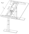
- the same telescopic frame 2 is in an extended position for a relative to the embodiment according to FIG figure 1 shown significantly longer tabletop 12 of about 2 m in length.
- the telescopic frame 2 comprises two telescopically extendable longitudinal profiles 14, 16, which are spaced apart from each other by a distance of about 50 cm and which are connected to one another at the front ends via longitudinal profiles extending transversely to the longitudinal axis (crossbeams) 18, 20 to form a closed frame the tops of the profiles 14, 16, 18, 20 define a support surface for the tabletop 4.
- the head profiles 18, 20 initially loose and are brought up to the assembly of the telescopic table frame 2.
- the telescopic table frame 2 is screwed to the tabletop 4, 12.
- the head profiles 18, 20 are then brought up to the telescopic table frame 2 and also screwed to the table top 4, 12.
- the telescopic table frame 2 is additionally clamped to the table top so that the table has even more stability.
- mounting plates 22, 24 are arranged with four through-holes for fastening bolts for the table legs 6.8. These mounting plates 22, 24 are preferably welded between the longitudinal profiles 14, 16 and on the head profiles 18, 20.
- lifting columns can also be used in which the electric motor is housed in a motor box attached to the upper end of the lifting column and then acts from there, for example via a claw coupling, on a spindle in the lifting column, causing it to be adjusted.
- the motor housing can be attached to the mounting plate or directly to the longitudinal profiles 14, 16.
- the synchronous control of the electric motors for adjusting the table height takes place via a circuit box 10 arranged in the middle between the spaced longitudinal profiles 14, 16 for accommodating a circuit, which is connected via cables to the two electric motors in the table legs 6, 8 and a switch, not shown.
- the telescopic table frame 2 is compared to that in FIG figure 1 shown in the fully collapsed position figure 2 shown in the more extended position, in which the longitudinal profiles 14, 16 are spaced apart and the slide-in profiles 26, 28 accommodated in these connect the longitudinal profiles 14, 16 with one another, the separation of the longitudinal profiles 14, 16 taking place in different planes.
- the telescopic table frame 2 is optimized for the long tabletop 12 with a length of approximately 2 meters.
- FIG 3 shows a further embodiment of a table frame according to the invention in its individual parts.
- the longitudinal profiles 14, 16 are connected at the right end to the mounting plate 24, for example welded.
- the mounting plate 24 is not flush with the tops of the rails 14,16 but is offset downwardly and outwardly, ie overhanging the ends of the rails 14,16, by small amounts.
- the head profile 20 is an angle profile in which the vertical leg becomes wider towards the middle. It has a clamping slot 30 near and parallel to its edge.
- the table frame is designed identically or as a mirror image at its other end, but this does not need to be discussed in more detail for the sake of simplicity.
- figure 4 shows a similar embodiment in the assembled state, with the protruding edge of the mounting plate 24 is inserted into the clamping slot 30.
- screws are passed through the four fastening holes on the lifting column and in the mounting plate 24 and screwed into the table top. These screws now pull the mounting plate towards the table top.
- the head profile 20 is also clamped between the mounting plate 24 and the table top.
- figure 5 shows the same embodiment in a modified assembly. Here the mounting plate 24 is shifted to the end of the clamping slot 30 . If the head profile 20 is now attached symmetrically to the underside of the table top, the lifting column is no longer directed towards the central longitudinal axis of the table top.
- Such an embodiment generally also requires a correspondingly asymmetrical design of the table base at the lower end of the lifting column.
Landscapes
- Tables And Desks Characterized By Structural Shape (AREA)
Description
- Die Erfindung betrifft ein Teleskoptischgestell zum Tragen einer Tischplatte eines Tisches in einer Arbeitshöhe, welches ausgebildet ist zur Befestigung von Tischfüßen, insbesondere für höhenverstellbare Tischfüße eines Bürotisches.
- Bekannte Tischgestelle bestehen aus mehreren miteinander verschweißten Metallprofilen zur Bildung eines vorzugsweise geschlossenen Profilrahmens, welcher eine sich in Einbaulage im Wesentlichen horizontal erstreckende Tischebene bildet, auf dem oberseitig eine Tischplatte befestigt ist und an dem ferner sich in Einbaulage vertikal und somit quer zur Tischebene erstreckende Tischfüße befestigt sind, welche den Tisch gegenüber dem Boden abstützen, sich also zwischen Tischgestell und Boden erstrecken. Die Tischfüße können je nach Befestigungsstelle des sich vertikal erstreckenden Tischbeins an dem auf dem aufstehenden Tischfuß entweder als T-, oder als L-Ausführung ausgebildet sein, um verschiedene Einbausituationen zu realisieren und die Kippstabilität bei größeren Tischlasten zu verbessern.
- Die Tischplatten von Bürotischen weisen üblicherweise eine Breite bzw. Tiefe zwischen 1000 - 1200mm sowie unterschiedliche Längen auf, vorzugweise 2000 bis 2500mm. Da die Tischgestelle gegenüber der Tischplatte üblicherweise zurücktreten, sind die Außenabmessungen der Tischgestelle insofern entsprechend kleiner.
- Bei modernen Tischen sind die Tischbeine vorzugsweise als höhenverstellbare Hubsäulen mit 2-3 teleskopartig ineinander schiebbaren Teleskopelementen ausgebildet. Die Höhenverstellung erfolgt normalerweise elektromotorisch mit einem Schneckengetriebe, das über eine Klauenkupplung in eine Spindel eingreift, die in den Hubsäulen verbaut ist.
- Ein solcher Tisch bzw. das Tischgestell muss eine definierte Quer- und Längssteifigkeit für den Tisch realisieren, welche in der EN 527-2 und -3, in den Vorgaben des Normenausschusses Bürowesen im DIN-Fachbericht Nr. 147 sowie in anderen international gültigen Normen festgelegt sind. Diese gibt ein Prüfungsverfahren für Arbeitstische und Büroschränke für die Bestimmung der Festigkeit und der Dauerhaltbarkeit beweglicher Teile vor.
- Bei bekannten Tischgestellen, z. B. dem der
DE 298 00 529 U1 , sind die Teleskopelemente der höhenverstellbaren Hubsäulen durch Traversen miteinander verbunden, die sich im Raum unterhalb der Tischplatte, beispielsweise in Kniehöhe, befinden und die Beinfreiheit des Benutzers beschränken. - Stand der Technik ist ebenfalls bekannt aus
DE 20 2011 050 924 U1 ,FR 1 291 776 A US 2,045,942 , sowieEP 0 956 791 A2 - Nachteilig sind die hohen Lagerhaltungskosten für verschiedene Tischvarianten und Größen, weil diese üblicherweise vorgefertigt verschweißt werden müssen und insofern relativ viel Lagerraum für verschieden große Tischgestelle für verschieden große Tischplatten benötigt werden.
- Ausgehend von diesem Stand der Technik liegt der Erfindung die Aufgabe zugrunde, diese Nachteile zumindest teilweise zu vermeiden und ein Tischgestell vorzusehen, welches die eingangs genannten Nachteile zumindest teilweise vermeidet und insbesondere die Lagerhaltungskosten für verschiedene Größen und Varianten reduziert.
- Diese Aufgabe wird bei einem Teleskoptischgestell der eingangs genannten Art bereits durch die unabhängigen Ansprüche gelöst.
- Das erfindungsgemäße Teleskoptischgestell ist teleskopartig verschiebbar ausgebildet, umfassend korrespondierend bzw. komplementär ausgebildete Profile, umfassend mindestens ein erstes Aufnahmeprofil zur längsverschieblichen Aufnahme mindestens eines weiteren Einsatzprofils. Allerdings ist zu berücksichtigen, dass die Erfindung nicht auf ein Profil mit nur zwei relativbeweglichen Profilen beschränkt ist, also durchaus drei oder mehr Profile eingesetzt werden können. Bei der Verwendung eines Aufnahmeprofils und mindestens einem in dieses einschiebbaren Einsatzprofiles hat es sich zur Realisierung einer gleichzeitigen Fixierung der Profile an der Unterseite einer Tischplatte sowie der Relativfixierung der beiden Profile in der gewünschten Sollposition als zweckmäßig erwiesen, dass beide Profile in bestimmten, vorzugsweise sich wiederholenden Abständen angeordnete Öffnungen aufweisen, die zudem größenmäßig so abgestimmt sind, dass durch diese eine Schraube oder ein Fixierungselement hindurchgesteckt werden kann.
- Wie zuvor erwähnt ist das Tischgestell zur Längsverstellung ausgebildet, umfasst also längsverstellbare Längsprofile, die vorzugsweise versetzt zueinander verstellbar sind, also nicht entlang einer gemeinsamen Ebene erstreckende Trennebenen umfasst. Das Tischgestell umfasst auch einen oder mehrere Querträger, die sich senkrecht zu den Längsträgern, im Allgemeinen parallel zu den Schmalseiten der Tischplatte, erstrecken. Bevorzugt sind die Querträger längsverstellbar ausgebildet, wobei dieses aber üblicherweise aus Gründen der Stabilität nicht der Fall ist. Die Querträger können sich als Kopfprofile an den Enden der Längsträger befinden. Diese Querträger können beispielsweise einfache Winkel- oder Rechteckprofile sein. Andere Gestaltungen sind selbstverständlich möglich, beispielsweise mit einer von den Enden des Querträgers zu seiner Mitte hin zunehmenden Breite, oder insbesondere als Kopfprofile mit einer ästhetischen oder identifizierenden Gestaltung der Außenseiten, etwa mit flächigen Verzierungen oder Firmenkennzeichen. Die Querträger können auch unsymmetrisch gestaltet und/oder montiert sein, wenn beispielsweise die Hubsäulen nicht auf die Mittellängsachse der Tischplatte ausgerichtet sind.
- Im Allgemeinen umfasst das erfindungsgemäße Teleskoptischgestell zwei längsverstellbare Längsprofile, die beispielsweise mit den Querträgern bzw. Kopfprofilen einen rechteckigen Rahmen bilden können. Es ist aber durchaus auch möglich, nur ein Längsprofil oder mehrere, beispielsweise drei oder vier, im erfindungsgemäßen Teleskoptischgestell anzuwenden.
- Dieser modulare Aufbau des erfindungsgemäßen Teleskoptischgestells aus einzelnen Bauteilen ermöglicht sowohl die Realisierung einer Vielzahl verschiedener Teleskoptischgestelle als auch die kompakte Verpackung der Einzelteile vor der Montage.
- Bei der besonders stabilen Ausführungsform sind die Profile des Tischrahmens als geschlossene Vierkantprofile ausgebildet, besonders bevorzugt mit einem Durchmesser von 40 x 40mm der aufnehmenden Profilkörper, in welche Einsatzprofile mit einer Größe von 35 x 35mm längsverschieblich einsetzbar sind. Als besonders zweckmäßig hat sich eine Wandstärke von 2mm unter Verwendung von Metallprofilen herausgestellt.
- Der besondere Vorteil dieser bevorzugten Ausgestaltung besteht darin, dass der Tischrahmen im zusammengeschobenen Zustand, also in dem vollständig eingeschobenen bzw. komprimierten Zustand, eine Größe aufweist, um auf einer Standard Europalette mit einer Länge von 120cm transportiert zu werden und erst bei der Montage zu dem Tischgestell zum Tragen der Tischplatte auf die jeweils benötigte Länge ausgezogen wird.
- Die Befestigungsmittel zur Befestigung des Tischgestells an der Unterseite der Tischplatte sind vorzugsweise ausgebildet, dass diese neben dieser Befestigung verwirklichen, sondern gleichzeitig auch die Fixierung des Tischgestells in der Sollposition verwirklichen. Vorzugsweise erfolgt dieses über Schrauben, welche in Öffnungen in dem Tischgestell einbringbar sind, also Öffnungen, die in bestimmten Positionen so fluchten, dass die Befestigungsschrauben bzw. -mittel durchsteckbar sind. Zur Befestigung an der Tischplatte und Fixierung des Gestells in der jeweils optimalen Sollposition ist das Tischgestell bevorzugt ausgebildet zum Hindurchstecken der Befestigungsmittel bzw. -schrauben, insbesondere durch die Profile hindurch in die Unterseite der Tischplatte.
- Die Einzelteile des Tischgestells bestehen vorzugsweise aus Metallprofilen, insbesondere mit einer Materialstärke von 1,5 bis 2mm. Das Tischgestell ist als selbsttragender und eigensteifer Rahmen ausgebildet, welcher eine sich vorzugsweise in der Horizontalen erstreckende Auflagefläche für die Tischplatte definiert.
- Das erfindungsgemäße Teleskoptischgestell zeichnet sich durch eine hervorragende Stabilität aus. Daher benötigt es im Gegensatz zu bekannten Gestellen keine sog. Quertraverse, d.h. keine stabilisierende Verbindung der Tischfüße bzw. unteren Abschnitte der Hubsäulen, welche die Beinfreiheit der Benutzer unerwünschter Weise beschränken würde. Bei der praktischen Ausführung zeigten die Tische mit dem erfindungsgemäßen Gestell im Pendelschlaghammertest nach den oben genannten Normen hervorragende Ergebnisse für Auslenkung und Schwingungsdämpfung. Ein bevorzugtes Ausführungsbeispiel der Erfindung ist in den Zeichnungen beispielhaft und nicht beschränkend dargestellt und wird im Folgenden näher beschrieben. In der folgenden ausführlichen Beschreibung wird auf die beigefügten Zeichnungen Bezug genommen, die Teil dieser bilden und in denen zur Veranschaulichung spezifische Ausführungsformen gezeigt sind, in der die Erfindung ausgeübt werden kann. In dieser Hinsicht wird Richtungsterminologie wie etwa "oben", "unten", "vorne", "hinten", "vorderes", "hinteres", usw. in Bezug auf die Orientierung der beschriebenen Figur(en) verwendet. Da Komponenten von Ausführungsformen in einer Anzahl verschiedener Orientierung positioniert werden können, dient die Richtungsterminologie zur Veranschaulichung und ist auf keinerlei Weise einschränkend. Es versteht sich, dass andere Ausführungsformen benutzt und strukturelle oder logische Änderungen vorgenommen werden können, ohne von dem Schutzumfang der vorliegenden Erfindung abzuweichen. Die folgende ausführliche Beschreibung ist nicht im einschränkenden Sinne aufzufassen. Im Rahmen dieser Beschreibung werden die Begriffe "verbunden", "angeschlossen" sowie "integriert" verwendet zum Beschreiben sowohl einer direkten als auch einer indirekten Verbindung, eines direkten oder indirekten Anschlusses sowie einer direkten oder indirekten Integration. In den Figuren werden identische oder ähnliche Elemente mit identischem Bezugszeichen versehen, soweit dieses zweckmäßig ist. Die Darstellungen in den Figuren sind im Wesentlichen maßstäblich. Zur Veranschaulichung von Details können jedoch bestimmte Bereiche für den Fachmann erkennbar übertrieben groß dargestellt sein. Darüber hinaus können die Zeichnungen plakativ vereinfacht sein und enthalten nicht jedes bei der praktischen Ausführung gegebenenfalls vorhandene Detail. Es zeigen:
- Figur 1
- eine perspektivische Ansicht eines Bürotisches mit einem erfindungsgemäßen Teleskoptischgestell in einer ersten Einbausituation für eine kurze Tischplatte;
- Figur 2
- eine perspektivische Ansicht eines Bürotisches mit einem erfindungsgemäßen Teleskoptischgestell in einer zweiten Einbausituation für eine lange Tischplatte;
- Figur 3
- eine andere Ausführungsform des erfindungsgemäßen Teleskoptischgestells in Explosionsdarstellung;
- Figur 4
- das Teleskoptischgestell nach
Figur 3 , montiert; - Figur 5
- das Teleskopttischgestell nach
Figur 4 in abgewandelter Montage. - Gleiche oder gleichwirkende Teile sind mit denselben Bezugszeichen versehen.
- In der
Figur 1 ist ein kartesisches Koordinatensystem eingezeichnet, um die verschiedenen Richtungen zu verdeutlichen. Demnach erstreckt sich die Längsrichtung entlang der X-Achse, die Querrichtung entlang der Y-Achse und die Höhenverstellung erfolgt entlang der Z-Achse. - Die vorliegende Ausführungsform umfasst ein Teleskoptischgestell 2, welches in der Längsachse des Tisches längenverstellbar ist.
- Das Teleskoptischgestell 2 trägt eine gestrichelt gezeichnete kurze Tischplatte 4 mit einer Länge von ca. 1,2m. An dem Teleskopgestell 2 sind an den beiden Stirnenden höhenverstellbar, also ebenfalls teleskopartig ausfahrbare Tischfüße 6, 8 befestigt, die aus einer abgesenkten Stellung in einer Arbeitshöhe von ungefähr 60cm über dem Boden in einer angehobene Stellung in einer Arbeitshöhe von ungefähr 1,2m stufenlos verstellbar sind, was vorzugsweise über Elektromotoren erfolgt, die in den Säulen der Tischfüße 6, 8 angeordnet sind und jeweils über eine Klauenkupplung eine in den Tischfüßen aufgenommene Spindel antreiben.
- In der
Figur 1 ist das Teleskoptischgestell 2 in der maximal zusammengeschobenen Position für eine relativ kurze Tischplatte 4 mit einer Länge von etwa 1,2m dargestellt. In derFigur 2 hingegen ist dasselbe Teleskopgestell 2 in einer ausgezogenen Position für eine im Verhältnis zur Ausführungsform gemäßFigur 1 wesentlich längere Tischplatte 12 von etwa 2 m Länge dargestellt. - Deutlich erkennbar umfasst das Teleskopgestell 2 zwei in einem Abstand von etwa 50cm zueinander beabstandete, teleskopartig ausziehbare Längsprofile 14, 16, die an den Stirnenden über quer zur Längsachse erstreckende Längsprofile erstreckende Kopfprofile (Querträger) 18, 20 miteinander zu einem geschlossenen Rahmen verbunden sind, wobei die Oberseiten der Profile 14, 16, 18, 20 eine Auflagefläche für die Tischplatte 4 definieren.
- Bei einer erfindungsgemäßen Ausführung sind die Kopfprofile 18, 20 zunächst lose und werden zur Montage an das Teleskoptischgestell 2 heran geführt. Zunächst wird das Teleskoptischgestell 2 mit der Tischplatte 4, 12 verschraubt. Anschließend werden die Kopfprofile 18, 20 an das Teleskoptischgestell 2 heran geführt und ebenfalls mit der Tischplatte 4, 12 verschraubt. Dabei wird das Teleskoptischgestell 2 zusätzlich zur Tischplatte verspannt, so dass der Tisch noch mehr Stabilität erhält.
- An den Stirnenden sind in dem Zwischenraum zwischen den Längsprofilen 14, 16 und den Kopfprofilen 18, 20 umfänglich eingeschlossen Montageplatten 22, 24 mit vier Durchgangslöchern für Befestigungsbolzen für die Tischfüße 6,8 angeordnet. Diese Montageplatten 22, 24 sind vorzugsweise zwischen den Längsprofilen 14, 16 und an den Kopfprofilen 18, 20 angeschweißt.
- Alternativ zu den dargestellten Ausführungsbeispiel können auch Hubsäulen eingesetzt werden, bei denen der Elektromotor in einem am oberen Ende der Hubsäulen befestigten Motorkasten untergebracht ist und dann von dort beispielsweise über eine Klauenkupplung auf eine Spindel in der Hubsäulen einwirkt, wodurch diese verstellt wird. In diesem Fall kann das Motorgehäuse an der Montageplatte oder auch direkt an den Längsprofilen 14, 16 befestigt sein.
- Die Synchronsteuerung der Elektromotoren zur Verstellung der Tischhöhe erfolgt über eine in der Mitte zwischen den beabstandeten Längsprofilen 14, 16 angeordneten Schaltungskasten 10 zur Aufnahme einer Schaltung, der über Kabel mit den beiden Elektromotoren in den Tischfüssen 6, 8 und einen nicht dargestellten Schalter verbunden sind.
- In den Oberseiten der Profile des Teleskoptischgestells sind distanziert voneinander mehrere Zapfen angeordnet, welche in Einbaulage in korrespondierende Löcher auf der Unterseite der Tischplatte 4 zu dessen Lagefixierung eingreifen. Neben diesen Zapfen können zur Fixierung in der Sollposition Schrauben durch fluchtend ausgerichtete Öffnungen durch die Profile hindurch in die Unterseite der Tischplatte verschraubt werden.
- Wie zuvor erwähnt, ist das Teleskoptischgestell 2 gegenüber der in der
Figur 1 dargestellten vollständig zusammengeschobenen Position in derFigur 2 in der weiter ausgezogen Position dargestellt, in welcher die Längsprofile 14, 16 voneinander beabstandet sind und die in diesen aufgenommenen Einschubprofile 26, 28 die Längsprofile 14, 16 miteinander verbinden, wobei die Trennung der Längsprofile 14, 16 in unterschiedlichen Ebenen erfolgt. In dieser ausgezogenen Stellung ist das Teleskoptischgestell 2 optimiert für die lange Tischplatte 12 mit einer Länge von ungefähr 2 Metern. -
Figur 3 zeigt eine weitere Ausführungsform eines erfindungsgemäßen Tischgestells in seinen Einzelteilen. Die Längsprofile 14, 16 sind am rechten Ende mit der Montageplatte 24 verbunden, beispielsweise verschweißt. Man bemerke, dass die Montageplatte 24 nicht bündig mit den Oberseiten der Längsprofile 14, 16 ist, sondern um geringe Beträge nach unten und außen, d.h. über die enden der Längsprofile 14, 16 hinaus stehend, versetzt ist. Das Kopfprofil 20 ist hierbei ein Winkelprofil, bei dem der senkrechte Schenkel zur Mitte hin breiter wird. Es weist einen Klemmschlitz 30 in der Nähe und parallel zu seiner Kante auf. Hier und in den folgenden Figuren ist das Tischgestell an seinem anderen Ende identisch bzw. spiegelbildlich gestaltet, worauf aber zur Vereinfachung nicht näher eingegangen zu werden braucht. -
Figur 4 stellt eine ähnliche Ausführungsform in montiertem Zustand dar, wobei der vorstehende Rand der Montageplatte 24 in den Klemmschlitz 30 eingeführt ist. Um nun das Gestell mit der unter der Montageplatte 24 anliegenden Hubsäule und der oben aufliegenden Tischplatte zu verbinden, werden durch die vier Befestigungslöcher an der Hubsäule und in der Montageplatte 24 Schrauben geführt und in die Tischplatte geschraubt. Diese Schrauben ziehen nun die Montageplatte auf die Tischplatte zu. Dabei wird auch das Kopfprofil 20 zwischen Montageplatte 24 und Tischplatte festgeklemmt.Figur 5 zeigt dieselbe Ausführungsform in einer abgewandelten Montage. Hier ist die Montageplatte 24 zum Ende des Klemmschlitzes 30 verschoben. Wenn das Kopfprofil 20 nun symmetrisch auf der Unterseite der Tischplatte befestigt wird, ist die Hubsäule nicht mehr auf die Mittellängsachse der Tischplatte gerichtet. Eine solche Ausführungsform erfordert im allgemeinen auch eine entsprechend unsymmetrische Gestaltung des Tischfußes am unteren Ende der Hubsäule. - Der Gegenstand der vorliegenden Erfindung ergibt sich nicht nur aus dem Gegenstand der einzelnen Patentansprüche, sondern aus der Kombination der einzelnen Patentansprüche untereinander.
-
- 2
- Teleskoptischgestell
- 4
- kurze Tischplatte
- 6
- Tischfuß
- 8
- Tischfuß
- 10
- Schaltungskasten
- 12
- lange Tischplatte
- 14
- Längsprofil
- 16
- Längsprofil
- 18
- Kopfprofil
- 20
- Kopfprofil
- 22
- Montagplatte
- 24
- Montagplatte
- 26
- Einschubprofil
- 28
- Einschubprofil
- 30
- Klemmschlitz
Claims (12)
- Teleskoptischgestell (2) zum Tragen einer Tischplatte (4, 12) eines Tisches in einer Arbeitshöhe, welches ausgebildet ist zur Befestigung von Tischfüßen (8), wobei das Teleskoptischgestell (2) längsverstellbar ausgebildet ist und Längsprofile (14, 16) umfasst, von denen mindestens ein erstes Aufnahmeprofil zur längsverschieblichen Aufnahme mindestens eines weiteren in das Aufnahmeprofil einstellbaren Einschubprofils (26, 28) ausgebildet ist, wobei das Teleskoptischgestell (2) modular aus mindestens zwei der zueinander beabstandeten Längsprofile (14, 16) und mindestens zwei als Kopfprofile (18, 20) ausgebildeten Querträger aufbaubar ist, und dadurch gekennzeichnet dass es Befestigungsmittel zur Befestigung des Tischgestells (2) an der Unterseite der Tischplatte (4, 12) umfasst, welche ausgebildet sind, um neben dieser Befestigung gleichzeitig eine Lagefixierung der beiden Längsprofile (14, 16) in der gewünschten Sollposition zu realisieren, dass zwei Längsprofile (14, 16) vorhanden sind, die zwischen ihren Enden mit Montageplatten (22, 24) zum Anbringen der Tischfüße verbunden sind, wobei die Kopfprofile (18, 20) als Winkelprofile mit Klemmschlitzen (30) in der Nähe und parallel zu den Kanten der Winkelprofile ausgebildet sind, wobei die Montageplatten nicht bündig mit den Oberseiten der Längsprofile sind, sondern nach unten und außen versetzt über die Enden der Längsprofile hinausreichen und ihre vorstehenden Ränder in die Klemmschlitze (30) in den Kopfprofilen (20) einführbar sind, wobei die senkrechten Schenkel der Winkelprofile zur Mitte hin breiter werden.
- Teleskoptischgestell (2) nach Anspruch 1, dadurch gekennzeichnet, dass in dem Aufnahmeprofil und in dem Einschubprofil (26, 28) jeweils mehrere korrespondierend angeordnete Löcher vorgesehen sind, durch welche in fluchtender Anordnung Befestigungsschrauben durchsteckbar und mit der Unterseite der Tischplatte verbindbar sind.
- Teleskoptischgestell (2) nach Anspruch 1 oder 2, dadurch gekennzeichnet, dass die längsverstellbaren Profile (14, 16) versetzt zueinander verstellbar sind.
- Teleskoptischgestell (2) nach einem der vorangehenden Ansprüche, dadurch gekennzeichnet, dass es längsverstellbare Querträger umfasst.
- Teleskoptischgestell (2) nach einem der vorangehenden Ansprüche, dadurch gekennzeichnet, dass die Querträger sich senkrecht zu den Längsprofilen erstrecken und als Kopfprofile (18, 20) an den Enden der Längsträger (14, 16) befinden.
- Tisch mit einer Tischplatte (4, 12) und einem Teleskoptischgestell (2) zum Tragen der Tischplatte in einer Arbeitshöhe, wobei das Teleskoptischgestell (2) ausgebildet ist zur Befestigung von Tischfüßen (8), wobei das Teleskoptischgestell (2) längsverstellbar ausgebildet ist und ein Längsprofil (14, 16) umfasst, von dem mindestens ein erstes Aufnahmeprofil (14, 16) zur längsverschieblichen Aufnahme mindestens eines weiteren in das Aufnahmeprofil einstellbaren Einschubprofils (26, 28) ausgebildet ist, wobei das Teleskoptischgestell (2) modular aus mindestens dem Längsprofil (14) und mindestens einem als Kopfprofil ausgebildeten Querträger (18, 20) aufbaubar ist, und dadurch gekennzeichnet dass es Befestigungsmittel zur Befestigung des Tischgestells (2) an der Unterseite der Tischplatte (4, 12) umfasst, welche ausgebildet sind, um neben dieser Befestigung gleichzeitig eine Lagefixierung des Längsprofils (14, 16) in der gewünschten Sollposition zu realisieren.
- Tisch nach Anspruch 6, dadurch gekennzeichnet, dass in dem Aufnahmeprofil (14, 16) und in dem Einschubprofil (26, 28) jeweils mehrere korrespondierend angeordnete Löcher vorgesehen sind, durch welche in fluchtender Anordnung Befestigungsschrauben durchsteckbar und mit der Unterseite der Tischplatte verbindbar sind.
- Tisch nach Anspruch 6 oder 7, dadurch gekennzeichnet, dass er mehrere längsverstellbaren Profile (14, 16) aufweist, die versetzt zueinander verstellbar sind.
- Tisch nach einem der Ansprüche 6 bis 8, dadurch gekennzeichnet, dass es längsverstellbare Querträger umfasst.
- Tisch nach Ansprüche 8 und 9, dadurch gekennzeichnet, dass die Querträger sich senkrecht zu den Längsträgern erstrecken und als Kopfprofile (18, 20) an den Enden der Längsträger (14, 16) befinden.
- Tisch nach einem der Ansprüche 6 bis 10, dadurch gekennzeichnet, dass zwei Längsprofile (14, 16) vorhanden sind, die zwischen ihren Enden mit Montageplatten (22, 24) zum Anbringen der Tischfüße verbunden sind, wobei Kopfprofile (20) als Winkelprofile mit Klemmschlitzen (30) in der Nähe und parallel zu den Kanten der Winkelprofile ausgebildet sind, wobei die Montageplatten nicht bündig mit den Oberseiten der Längsprofile sind, sondern nach unten und außen versetzt über die Enden der Längsprofile hinausreichen und ihre vorstehenden Ränder in die Klemmschlitze (30) in den Kopfprofilen (20) einführbar sind, wobei die senkrechten Schenkel der Winkelprofile zur Mitte hin breiter werden.
- Verfahren zur Montage eines Teleskoptischgestells (2) gemäß einem der Ansprüche 1 bis 5 mit einer Tischplatte (4, 12) zur Bildung eines Tisches nach einem der Ansprüche 6 bis 11, wobei die Kopfprofile (18, 20) zunächst lose sind und zur Montage an das Teleskoptischgestell (2) herangeführt werden, wobei zunächst das Teleskoptischgestell (2) (2) mit der Tischplatte (4, 12) verschraubt wird und anschließend die Kopfprofile (18, 20) an das Teleskoptischgestell (2) herangeführt und ebenfalls mit der Tischplatte (4, 12) verschraubt werden und wobei das Teleskoptischgestell (2) zusätzlich zur Tischplatte (4, 12) verspannt wird, so dass der Tisch mehr Stabilität erhält.
Applications Claiming Priority (2)
| Application Number | Priority Date | Filing Date | Title |
|---|---|---|---|
| DE102015105827.8A DE102015105827A1 (de) | 2015-04-16 | 2015-04-16 | Tischgestell für einen Tisch |
| PCT/EP2016/058029 WO2016166107A1 (de) | 2015-04-16 | 2016-04-12 | Tischgestell für einen tisch |
Publications (2)
| Publication Number | Publication Date |
|---|---|
| EP3282892A1 EP3282892A1 (de) | 2018-02-21 |
| EP3282892B1 true EP3282892B1 (de) | 2022-03-09 |
Family
ID=55702006
Family Applications (1)
| Application Number | Title | Priority Date | Filing Date |
|---|---|---|---|
| EP16715575.3A Active EP3282892B1 (de) | 2015-04-16 | 2016-04-12 | Tischgestell für einen tisch |
Country Status (7)
| Country | Link |
|---|---|
| US (1) | US11089864B2 (de) |
| EP (1) | EP3282892B1 (de) |
| CN (1) | CN107529881B (de) |
| DE (1) | DE102015105827A1 (de) |
| DK (1) | DK3282892T3 (de) |
| ES (1) | ES2912285T3 (de) |
| WO (1) | WO2016166107A1 (de) |
Cited By (2)
| Publication number | Priority date | Publication date | Assignee | Title |
|---|---|---|---|---|
| US12207730B2 (en) | 2022-07-08 | 2025-01-28 | CKnapp Sales, Inc. | Height adjustable angled desks |
| US12622510B2 (en) | 2022-08-12 | 2026-05-12 | Qidong Vision Mounts Manufacturing Co., Ltd. | Electric height-adjustable desk |
Families Citing this family (21)
| Publication number | Priority date | Publication date | Assignee | Title |
|---|---|---|---|---|
| GB2541517B (en) | 2015-07-01 | 2021-04-21 | Fellowes Inc | Variable height desktop workstation system |
| SE1651505A1 (sv) * | 2016-11-17 | 2018-05-02 | Polstiernan Ind Ab | A collapsible power-driven table stand, and a table comprising such a table stand |
| US10842258B2 (en) | 2017-09-18 | 2020-11-24 | Fellowes, Inc. | Variable height platform system |
| CN111132578B (zh) * | 2017-09-18 | 2022-05-17 | 斐乐公司 | 高度可变平台系统 |
| US10424408B2 (en) * | 2018-01-05 | 2019-09-24 | Express Scripts Strategic Development, Inc. | Pharmacy order processing system |
| EP3764841B1 (de) * | 2018-03-14 | 2024-12-25 | Linak A/S | Gestell für einen tisch |
| CN112074210B (zh) | 2018-05-04 | 2021-11-16 | 珀品有限公司 | 免用工具安装的附接组件 |
| USD880200S1 (en) * | 2018-05-24 | 2020-04-07 | Seville Classics Inc. | Table |
| US20200154876A1 (en) * | 2018-11-19 | 2020-05-21 | Choice Industries Corp. | Electrical table carrier mechanism |
| CA3061786C (en) * | 2018-11-20 | 2024-03-19 | Square Grove Llc | Vertically adjustable desk with under-carriage mounting system |
| USD911087S1 (en) * | 2019-02-19 | 2021-02-23 | CKnapp Sales, Inc. | Stabilizer bar |
| TWM601048U (zh) * | 2019-05-15 | 2020-09-11 | 第一傳動科技股份有限公司 | 易於組裝調整的電動桌腳架 |
| CN110934420A (zh) * | 2019-12-18 | 2020-03-31 | 嵊州市昇华机械科技有限公司 | 一种快速安装的电动升降办公桌 |
| CN111436746B (zh) * | 2020-04-23 | 2024-11-12 | 常州市凯迪电器股份有限公司 | 一种快速组装的桌面支架 |
| USD926498S1 (en) * | 2020-04-27 | 2021-08-03 | Yajun Hu | Gaming desk |
| USD931660S1 (en) * | 2020-05-29 | 2021-09-28 | Yajun Hu | Gaming desk |
| JP7469212B2 (ja) | 2020-10-28 | 2024-04-16 | 株式会社オカムラ | 天板付き什器 |
| CN113276950A (zh) * | 2021-05-19 | 2021-08-20 | 东风商用车有限公司 | 可调式车架横梁 |
| CN113633094B (zh) * | 2021-09-10 | 2022-08-05 | 浙江迈德维智能科技有限公司 | 一种电动式自动升降保健桌 |
| CN114587065A (zh) * | 2022-02-25 | 2022-06-07 | 立讯精密工业股份有限公司 | 桌板组件、升降架组件及升降桌 |
| TWM643891U (zh) * | 2023-04-27 | 2023-07-11 | 第一傳動科技股份有限公司 | 電動桌框結構 |
Family Cites Families (15)
| Publication number | Priority date | Publication date | Assignee | Title |
|---|---|---|---|---|
| DE924C (de) * | 1877-07-02 | G. HEGER, Architekt, in Berlin | Rohraufsatz | |
| US2045942A (en) * | 1935-04-05 | 1936-06-30 | Samuel C Brody | Support |
| FR1291776A (fr) * | 1961-03-18 | 1962-04-27 | Sncf | éléments de construction, de charpentes ou casiers de dimensions variables dans un volume quelconque |
| GB1385736A (en) * | 1971-09-15 | 1975-02-26 | Kartell Spa | Assemblable support structure for tables and the like |
| DE29800529U1 (de) * | 1998-01-15 | 1998-03-26 | Krautheim, Harald, 34399 Oberweser | Untergestell für einen höhenverstellbaren Tisch |
| IT1299780B1 (it) | 1998-04-17 | 2000-04-04 | Segato Sergio Ditta Individual | Struttura di supporto per piani di tavoli, scrivanie o simili |
| NL1011454C2 (nl) | 1999-03-04 | 2000-09-05 | Argo Office B V | In hoogte verstelbare steun voor het ondersteunen van een tafelblad. |
| US7934459B2 (en) * | 2005-09-20 | 2011-05-03 | Brian Frazier | Ergonomic workstation with raising and lowering elements |
| CN200962970Y (zh) | 2006-11-03 | 2007-10-24 | 夺标贸易(深圳)有限公司 | 手摇式升降书桌架 |
| US8348071B1 (en) * | 2007-07-02 | 2013-01-08 | Perez Janlert | Adjustable air handler stand and filter rack |
| US8967054B2 (en) * | 2011-06-03 | 2015-03-03 | Kimball International, Inc. | Office desking system |
| DE202011050924U1 (de) * | 2011-08-05 | 2011-11-08 | Concorde Reisemobile Gmbh | Tisch in einem Innenraum eines Reisemobils |
| WO2013104639A1 (en) * | 2012-01-10 | 2013-07-18 | Skovby Møbelfabrik A/S | Extension table with multiple legs |
| CA2823471A1 (en) * | 2013-08-08 | 2015-02-08 | David Hutchison | Expandable and collapsible table with nesting leaves |
| TWM486995U (zh) * | 2014-04-03 | 2014-10-01 | Timotion Technology Co Ltd | 易於展收的電動桌腳架 |
-
2015
- 2015-04-16 DE DE102015105827.8A patent/DE102015105827A1/de not_active Withdrawn
-
2016
- 2016-04-12 CN CN201680022334.6A patent/CN107529881B/zh active Active
- 2016-04-12 EP EP16715575.3A patent/EP3282892B1/de active Active
- 2016-04-12 WO PCT/EP2016/058029 patent/WO2016166107A1/de not_active Ceased
- 2016-04-12 US US15/565,941 patent/US11089864B2/en active Active
- 2016-04-12 DK DK16715575.3T patent/DK3282892T3/da active
- 2016-04-12 ES ES16715575T patent/ES2912285T3/es active Active
Cited By (2)
| Publication number | Priority date | Publication date | Assignee | Title |
|---|---|---|---|---|
| US12207730B2 (en) | 2022-07-08 | 2025-01-28 | CKnapp Sales, Inc. | Height adjustable angled desks |
| US12622510B2 (en) | 2022-08-12 | 2026-05-12 | Qidong Vision Mounts Manufacturing Co., Ltd. | Electric height-adjustable desk |
Also Published As
| Publication number | Publication date |
|---|---|
| ES2912285T3 (es) | 2022-05-25 |
| US20180103753A1 (en) | 2018-04-19 |
| DE102015105827A1 (de) | 2016-10-20 |
| CN107529881A (zh) | 2018-01-02 |
| CN107529881B (zh) | 2021-12-28 |
| DK3282892T3 (da) | 2022-05-16 |
| EP3282892A1 (de) | 2018-02-21 |
| US11089864B2 (en) | 2021-08-17 |
| WO2016166107A1 (de) | 2016-10-20 |
Similar Documents
| Publication | Publication Date | Title |
|---|---|---|
| WO2016166107A1 (de) | Tischgestell für einen tisch | |
| EP3282894B1 (de) | Tischgestell für einen tisch | |
| EP0362614B1 (de) | Arbeitsplatzvorrichtung | |
| EP0307620A1 (de) | Arbeitstisch | |
| DE29623554U1 (de) | Eckverbindung für ein Rahmengestell | |
| DE202010002342U1 (de) | Montagetisch zur Bestückung und Verdrahtung von Schaltschrank-Elementen | |
| EP0830825A2 (de) | Koppelelement für ein Möbelgestell, Bausatz für den Zusammenbau eines Möbelständers und Baukasten für den Zusammenbau eines Möbelstücks | |
| DE19615759C2 (de) | Schaltschrank mit Sockel und Rahmengestell | |
| EP2526823A1 (de) | Schrankelement mit einem Schrankauszug | |
| DE29611613U1 (de) | Arbeitstisch | |
| DE202008012023U1 (de) | Tischkonstruktion | |
| EP0417177B1 (de) | Regalsystem | |
| EP0070422B1 (de) | Arbeitstisch, insbesondere Bürotisch | |
| DE9317453U1 (de) | Möbelfuß für Kastenmöbel | |
| DE3401468C2 (de) | Tragvorrichtung für elektrische Einrichtungen | |
| DE29709829U1 (de) | Tragkonstruktion | |
| EP0275001B1 (de) | Transportgestell für Karosseriebestandteile | |
| DE202012104001U1 (de) | Tisch, insbesondere Schreib- oder Arbeitstisch | |
| DE102019117190A1 (de) | Einrichtung zum stirnseitigen Abschluss einer Grabenverbau-Einheit | |
| EP2183994B1 (de) | Arbeitsplatz | |
| DE677621C (de) | Bauruestung zum Aufbau von Flugzeugruempfen, -tragflaechen u. dgl. | |
| DE202016004838U1 (de) | Tischgestell für ein höhenverstellbares Tischmöbel | |
| DE2432490C3 (de) | Versetzbare Trennwand | |
| DE102024108108A1 (de) | Befestigungseinrichtung und Anordnung | |
| DE202016000219U1 (de) | Auszugseinheit für ein Möbelstück mit zwei verbundenen Schubladen |
Legal Events
| Date | Code | Title | Description |
|---|---|---|---|
| STAA | Information on the status of an ep patent application or granted ep patent |
Free format text: STATUS: THE INTERNATIONAL PUBLICATION HAS BEEN MADE |
|
| PUAI | Public reference made under article 153(3) epc to a published international application that has entered the european phase |
Free format text: ORIGINAL CODE: 0009012 |
|
| STAA | Information on the status of an ep patent application or granted ep patent |
Free format text: STATUS: REQUEST FOR EXAMINATION WAS MADE |
|
| 17P | Request for examination filed |
Effective date: 20171005 |
|
| AK | Designated contracting states |
Kind code of ref document: A1 Designated state(s): AL AT BE BG CH CY CZ DE DK EE ES FI FR GB GR HR HU IE IS IT LI LT LU LV MC MK MT NL NO PL PT RO RS SE SI SK SM TR |
|
| AX | Request for extension of the european patent |
Extension state: BA ME |
|
| STAA | Information on the status of an ep patent application or granted ep patent |
Free format text: STATUS: EXAMINATION IS IN PROGRESS |
|
| DAV | Request for validation of the european patent (deleted) | ||
| DAX | Request for extension of the european patent (deleted) | ||
| 17Q | First examination report despatched |
Effective date: 20180724 |
|
| RAP1 | Party data changed (applicant data changed or rights of an application transferred) |
Owner name: DEWERTOKIN TECHNOLOGY GROUP CO., LTD. |
|
| GRAP | Despatch of communication of intention to grant a patent |
Free format text: ORIGINAL CODE: EPIDOSNIGR1 |
|
| STAA | Information on the status of an ep patent application or granted ep patent |
Free format text: STATUS: GRANT OF PATENT IS INTENDED |
|
| INTG | Intention to grant announced |
Effective date: 20211126 |
|
| GRAS | Grant fee paid |
Free format text: ORIGINAL CODE: EPIDOSNIGR3 |
|
| GRAA | (expected) grant |
Free format text: ORIGINAL CODE: 0009210 |
|
| STAA | Information on the status of an ep patent application or granted ep patent |
Free format text: STATUS: THE PATENT HAS BEEN GRANTED |
|
| AK | Designated contracting states |
Kind code of ref document: B1 Designated state(s): AL AT BE BG CH CY CZ DE DK EE ES FI FR GB GR HR HU IE IS IT LI LT LU LV MC MK MT NL NO PL PT RO RS SE SI SK SM TR |
|
| REG | Reference to a national code |
Ref country code: GB Ref legal event code: FG4D Free format text: NOT ENGLISH |
|
| REG | Reference to a national code |
Ref country code: CH Ref legal event code: EP Ref country code: AT Ref legal event code: REF Ref document number: 1473435 Country of ref document: AT Kind code of ref document: T Effective date: 20220315 |
|
| REG | Reference to a national code |
Ref country code: IE Ref legal event code: FG4D Free format text: LANGUAGE OF EP DOCUMENT: GERMAN |
|
| REG | Reference to a national code |
Ref country code: DE Ref legal event code: R096 Ref document number: 502016014613 Country of ref document: DE |
|
| REG | Reference to a national code |
Ref country code: SE Ref legal event code: TRGR |
|
| REG | Reference to a national code |
Ref country code: DK Ref legal event code: T3 Effective date: 20220512 |
|
| REG | Reference to a national code |
Ref country code: NL Ref legal event code: FP |
|
| REG | Reference to a national code |
Ref country code: ES Ref legal event code: FG2A Ref document number: 2912285 Country of ref document: ES Kind code of ref document: T3 Effective date: 20220525 |
|
| REG | Reference to a national code |
Ref country code: LT Ref legal event code: MG9D |
|
| PG25 | Lapsed in a contracting state [announced via postgrant information from national office to epo] |
Ref country code: RS Free format text: LAPSE BECAUSE OF FAILURE TO SUBMIT A TRANSLATION OF THE DESCRIPTION OR TO PAY THE FEE WITHIN THE PRESCRIBED TIME-LIMIT Effective date: 20220309 Ref country code: NO Free format text: LAPSE BECAUSE OF FAILURE TO SUBMIT A TRANSLATION OF THE DESCRIPTION OR TO PAY THE FEE WITHIN THE PRESCRIBED TIME-LIMIT Effective date: 20220609 Ref country code: LT Free format text: LAPSE BECAUSE OF FAILURE TO SUBMIT A TRANSLATION OF THE DESCRIPTION OR TO PAY THE FEE WITHIN THE PRESCRIBED TIME-LIMIT Effective date: 20220309 Ref country code: HR Free format text: LAPSE BECAUSE OF FAILURE TO SUBMIT A TRANSLATION OF THE DESCRIPTION OR TO PAY THE FEE WITHIN THE PRESCRIBED TIME-LIMIT Effective date: 20220309 Ref country code: BG Free format text: LAPSE BECAUSE OF FAILURE TO SUBMIT A TRANSLATION OF THE DESCRIPTION OR TO PAY THE FEE WITHIN THE PRESCRIBED TIME-LIMIT Effective date: 20220609 |
|
| PG25 | Lapsed in a contracting state [announced via postgrant information from national office to epo] |
Ref country code: LV Free format text: LAPSE BECAUSE OF FAILURE TO SUBMIT A TRANSLATION OF THE DESCRIPTION OR TO PAY THE FEE WITHIN THE PRESCRIBED TIME-LIMIT Effective date: 20220309 Ref country code: GR Free format text: LAPSE BECAUSE OF FAILURE TO SUBMIT A TRANSLATION OF THE DESCRIPTION OR TO PAY THE FEE WITHIN THE PRESCRIBED TIME-LIMIT Effective date: 20220610 Ref country code: FI Free format text: LAPSE BECAUSE OF FAILURE TO SUBMIT A TRANSLATION OF THE DESCRIPTION OR TO PAY THE FEE WITHIN THE PRESCRIBED TIME-LIMIT Effective date: 20220309 |
|
| PG25 | Lapsed in a contracting state [announced via postgrant information from national office to epo] |
Ref country code: SM Free format text: LAPSE BECAUSE OF FAILURE TO SUBMIT A TRANSLATION OF THE DESCRIPTION OR TO PAY THE FEE WITHIN THE PRESCRIBED TIME-LIMIT Effective date: 20220309 Ref country code: SK Free format text: LAPSE BECAUSE OF FAILURE TO SUBMIT A TRANSLATION OF THE DESCRIPTION OR TO PAY THE FEE WITHIN THE PRESCRIBED TIME-LIMIT Effective date: 20220309 Ref country code: RO Free format text: LAPSE BECAUSE OF FAILURE TO SUBMIT A TRANSLATION OF THE DESCRIPTION OR TO PAY THE FEE WITHIN THE PRESCRIBED TIME-LIMIT Effective date: 20220309 Ref country code: PT Free format text: LAPSE BECAUSE OF FAILURE TO SUBMIT A TRANSLATION OF THE DESCRIPTION OR TO PAY THE FEE WITHIN THE PRESCRIBED TIME-LIMIT Effective date: 20220711 Ref country code: EE Free format text: LAPSE BECAUSE OF FAILURE TO SUBMIT A TRANSLATION OF THE DESCRIPTION OR TO PAY THE FEE WITHIN THE PRESCRIBED TIME-LIMIT Effective date: 20220309 Ref country code: CZ Free format text: LAPSE BECAUSE OF FAILURE TO SUBMIT A TRANSLATION OF THE DESCRIPTION OR TO PAY THE FEE WITHIN THE PRESCRIBED TIME-LIMIT Effective date: 20220309 |
|
| PG25 | Lapsed in a contracting state [announced via postgrant information from national office to epo] |
Ref country code: PL Free format text: LAPSE BECAUSE OF FAILURE TO SUBMIT A TRANSLATION OF THE DESCRIPTION OR TO PAY THE FEE WITHIN THE PRESCRIBED TIME-LIMIT Effective date: 20220309 Ref country code: IS Free format text: LAPSE BECAUSE OF FAILURE TO SUBMIT A TRANSLATION OF THE DESCRIPTION OR TO PAY THE FEE WITHIN THE PRESCRIBED TIME-LIMIT Effective date: 20220709 Ref country code: AL Free format text: LAPSE BECAUSE OF FAILURE TO SUBMIT A TRANSLATION OF THE DESCRIPTION OR TO PAY THE FEE WITHIN THE PRESCRIBED TIME-LIMIT Effective date: 20220309 |
|
| REG | Reference to a national code |
Ref country code: CH Ref legal event code: PL |
|
| REG | Reference to a national code |
Ref country code: DE Ref legal event code: R097 Ref document number: 502016014613 Country of ref document: DE |
|
| REG | Reference to a national code |
Ref country code: BE Ref legal event code: MM Effective date: 20220430 |
|
| PLBE | No opposition filed within time limit |
Free format text: ORIGINAL CODE: 0009261 |
|
| STAA | Information on the status of an ep patent application or granted ep patent |
Free format text: STATUS: NO OPPOSITION FILED WITHIN TIME LIMIT |
|
| PG25 | Lapsed in a contracting state [announced via postgrant information from national office to epo] |
Ref country code: MC Free format text: LAPSE BECAUSE OF FAILURE TO SUBMIT A TRANSLATION OF THE DESCRIPTION OR TO PAY THE FEE WITHIN THE PRESCRIBED TIME-LIMIT Effective date: 20220309 Ref country code: LU Free format text: LAPSE BECAUSE OF NON-PAYMENT OF DUE FEES Effective date: 20220412 Ref country code: LI Free format text: LAPSE BECAUSE OF NON-PAYMENT OF DUE FEES Effective date: 20220430 Ref country code: CH Free format text: LAPSE BECAUSE OF NON-PAYMENT OF DUE FEES Effective date: 20220430 |
|
| 26N | No opposition filed |
Effective date: 20221212 |
|
| PG25 | Lapsed in a contracting state [announced via postgrant information from national office to epo] |
Ref country code: SI Free format text: LAPSE BECAUSE OF FAILURE TO SUBMIT A TRANSLATION OF THE DESCRIPTION OR TO PAY THE FEE WITHIN THE PRESCRIBED TIME-LIMIT Effective date: 20220309 Ref country code: BE Free format text: LAPSE BECAUSE OF NON-PAYMENT OF DUE FEES Effective date: 20220430 |
|
| GBPC | Gb: european patent ceased through non-payment of renewal fee |
Effective date: 20220609 |
|
| PG25 | Lapsed in a contracting state [announced via postgrant information from national office to epo] |
Ref country code: IE Free format text: LAPSE BECAUSE OF NON-PAYMENT OF DUE FEES Effective date: 20220412 |
|
| PG25 | Lapsed in a contracting state [announced via postgrant information from national office to epo] |
Ref country code: GB Free format text: LAPSE BECAUSE OF NON-PAYMENT OF DUE FEES Effective date: 20220609 |
|
| P01 | Opt-out of the competence of the unified patent court (upc) registered |
Effective date: 20230620 |
|
| PG25 | Lapsed in a contracting state [announced via postgrant information from national office to epo] |
Ref country code: IT Free format text: LAPSE BECAUSE OF FAILURE TO SUBMIT A TRANSLATION OF THE DESCRIPTION OR TO PAY THE FEE WITHIN THE PRESCRIBED TIME-LIMIT Effective date: 20220309 |
|
| PG25 | Lapsed in a contracting state [announced via postgrant information from national office to epo] |
Ref country code: HU Free format text: LAPSE BECAUSE OF FAILURE TO SUBMIT A TRANSLATION OF THE DESCRIPTION OR TO PAY THE FEE WITHIN THE PRESCRIBED TIME-LIMIT; INVALID AB INITIO Effective date: 20160412 |
|
| PG25 | Lapsed in a contracting state [announced via postgrant information from national office to epo] |
Ref country code: MK Free format text: LAPSE BECAUSE OF FAILURE TO SUBMIT A TRANSLATION OF THE DESCRIPTION OR TO PAY THE FEE WITHIN THE PRESCRIBED TIME-LIMIT Effective date: 20220309 Ref country code: CY Free format text: LAPSE BECAUSE OF FAILURE TO SUBMIT A TRANSLATION OF THE DESCRIPTION OR TO PAY THE FEE WITHIN THE PRESCRIBED TIME-LIMIT Effective date: 20220309 |
|
| PG25 | Lapsed in a contracting state [announced via postgrant information from national office to epo] |
Ref country code: MT Free format text: LAPSE BECAUSE OF FAILURE TO SUBMIT A TRANSLATION OF THE DESCRIPTION OR TO PAY THE FEE WITHIN THE PRESCRIBED TIME-LIMIT Effective date: 20220309 |
|
| PGFP | Annual fee paid to national office [announced via postgrant information from national office to epo] |
Ref country code: DK Payment date: 20250328 Year of fee payment: 10 Ref country code: NL Payment date: 20250325 Year of fee payment: 10 |
|
| PGFP | Annual fee paid to national office [announced via postgrant information from national office to epo] |
Ref country code: DE Payment date: 20250411 Year of fee payment: 10 |
|
| PGFP | Annual fee paid to national office [announced via postgrant information from national office to epo] |
Ref country code: ES Payment date: 20250512 Year of fee payment: 10 |
|
| PGFP | Annual fee paid to national office [announced via postgrant information from national office to epo] |
Ref country code: FR Payment date: 20250429 Year of fee payment: 10 |
|
| PGFP | Annual fee paid to national office [announced via postgrant information from national office to epo] |
Ref country code: AT Payment date: 20250321 Year of fee payment: 10 |
|
| PGFP | Annual fee paid to national office [announced via postgrant information from national office to epo] |
Ref country code: SE Payment date: 20250422 Year of fee payment: 10 |
|
| PG25 | Lapsed in a contracting state [announced via postgrant information from national office to epo] |
Ref country code: TR Free format text: LAPSE BECAUSE OF FAILURE TO SUBMIT A TRANSLATION OF THE DESCRIPTION OR TO PAY THE FEE WITHIN THE PRESCRIBED TIME-LIMIT Effective date: 20220309 |