EP0956791A2 - Supporting structure for tops of tables, desks or similar - Google Patents
Supporting structure for tops of tables, desks or similar Download PDFInfo
- Publication number
- EP0956791A2 EP0956791A2 EP99107269A EP99107269A EP0956791A2 EP 0956791 A2 EP0956791 A2 EP 0956791A2 EP 99107269 A EP99107269 A EP 99107269A EP 99107269 A EP99107269 A EP 99107269A EP 0956791 A2 EP0956791 A2 EP 0956791A2
- Authority
- EP
- European Patent Office
- Prior art keywords
- elements
- tubular
- assembly
- hereinbefore
- uprights
- Prior art date
- Legal status (The legal status is an assumption and is not a legal conclusion. Google has not performed a legal analysis and makes no representation as to the accuracy of the status listed.)
- Pending
Links
- 238000003780 insertion Methods 0.000 claims abstract description 11
- 230000037431 insertion Effects 0.000 claims abstract description 11
- 125000006850 spacer group Chemical group 0.000 claims description 30
- 239000000203 mixture Substances 0.000 claims description 10
- 230000013011 mating Effects 0.000 claims description 9
- 239000007787 solid Substances 0.000 claims 1
- 230000008878 coupling Effects 0.000 description 6
- 238000010168 coupling process Methods 0.000 description 6
- 238000005859 coupling reaction Methods 0.000 description 6
- 239000002184 metal Substances 0.000 description 2
- 238000010276 construction Methods 0.000 description 1
- 230000001419 dependent effect Effects 0.000 description 1
- 239000013013 elastic material Substances 0.000 description 1
- 238000007493 shaping process Methods 0.000 description 1
Images

Classifications
-
- A—HUMAN NECESSITIES
- A47—FURNITURE; DOMESTIC ARTICLES OR APPLIANCES; COFFEE MILLS; SPICE MILLS; SUCTION CLEANERS IN GENERAL
- A47B—TABLES; DESKS; OFFICE FURNITURE; CABINETS; DRAWERS; GENERAL DETAILS OF FURNITURE
- A47B17/00—Writing-tables
- A47B17/003—Writing-tables made of metal
-
- A—HUMAN NECESSITIES
- A47—FURNITURE; DOMESTIC ARTICLES OR APPLIANCES; COFFEE MILLS; SPICE MILLS; SUCTION CLEANERS IN GENERAL
- A47B—TABLES; DESKS; OFFICE FURNITURE; CABINETS; DRAWERS; GENERAL DETAILS OF FURNITURE
- A47B13/00—Details of tables or desks
- A47B13/02—Underframes
- A47B13/06—Underframes of metal
-
- A—HUMAN NECESSITIES
- A47—FURNITURE; DOMESTIC ARTICLES OR APPLIANCES; COFFEE MILLS; SPICE MILLS; SUCTION CLEANERS IN GENERAL
- A47B—TABLES; DESKS; OFFICE FURNITURE; CABINETS; DRAWERS; GENERAL DETAILS OF FURNITURE
- A47B2200/00—General construction of tables or desks
- A47B2200/0011—Underframes
- A47B2200/002—Legs
- A47B2200/0027—Desks with I-shaped leg
Definitions
- This invention concerns a supporting structure for the tops of tables, desks or similar, as set forth in the main claim.
- the invention is employed in the field of furniture, particularly but not exclusively office furniture, as a structure suitable to support the tops of tables, desks, writing-tables or similar, enabling the tops to be composed in a modular manner.
- the state of the art includes a plurality of structures suitable to support the tops of furniture components such as tables, desks or similar.
- One type of support which is particularly common comprises a single, substantially horizontal beam element associated at the ends with vertical uprights functioning as legs.
- the beam elements and the uprights consist of box-like profiles made of sheet metal, normally obtained by coupling two C-shaped elements, and are associated with each other by means of connection elements, such as hooks, brackets, plates or similar, attached on the outside of the profiles.
- This type of supporting structure is very much appreciated due to the simplicity of its construction and its limited production costs; it can be composed in many different ways and allows to achieve furniture components with a plurality of differently arranged surfaces.
- the main disadvantage of this embodiment is that the structure is not very stable when assembled, as it is obtained by using the connection elements, which do not always guarantee an adequate hold.
- connection elements and attachment means To obtain a greater stability of the assembly connection, it is therefore necessary to provide a considerable number of connection elements and attachment means and/or oversize said elements and means.
- a further disadvantage is that the structures known to the state of the art are difficult to assemble.
- the purpose of the invention is to provide a supporting structure for the tops of tables, desks or similar which will guarantee a stable and safe connection between the uprights and the beam elements, preventing any possible deformations even when there are heavy stresses, using a limited number of connection and attachment elements and limiting to a minimum the number of said elements arranged in view.
- Another purpose of the invention is to achieve an aesthetically pleasing and extremely versatile supporting structure which will allow considerable possibilities of composition, even angled, of the surfaces and/or variations in size of the top, in height and/or in length.
- a further purpose of the invention is to achieve an economic supporting structure, easy and quick to assemble.
- the supporting structure according to the invention provides beam elements and uprights consisting of tubular profiles, each achieved in a single tube, which are associated together by means of attachment means cooperating with assembly elements suitable to be inserted and clamped to the ends of the tubular profiles.
- Each of the assembly elements has at least an insertion seating suitable to cooperate with the attachment means.
- a first tubular profile is equipped with the assembly element, for example inserted into one of the ends in a retracted position;
- the second of the tubular profiles is provided with means, for example through holes or eyelets, into which mating attachment means are inserted, which couple with and constrain the assembly element on the first tubular profile.
- a spacer element is inserted into the second tubular profile with the function of preventing the tubular profile from being crushed during the clamping action of the attachment means.
- the spacer element has through holes cooperating with the through holes provided on the second tubular profile which allow the attachment means to pass.
- the assembly elements and/or the spacer elements are constrained together and engaged inside the respective tubular profiles, in correspondence with at least one of the respective ends.
- the assembly elements and/or the spacer elements include elastic means which allow them to contract so they can be inserted inside the tubular profiles and subsequently expand inside so that they are clamped and engaged inside.
- the assembly elements are attached to the tubular profile by specific, auxiliary clamping means.
- the assembly elements and/or the spacer elements include positioning means cooperating with corresponding positioning means made on the tubular profiles.
- the assembly elements and/or the spacer elements include positioning and retaining means cooperating frontally in abutment with the perimeter edge of the tubular profiles.
- the assembly elements and/or the spacer elements include screw seatings cooperating with the attachment means to attach plates to support and associate the table top.
- the beam elements in the case of beam elements arranged on the same plane and associated with a single upright on opposite sides thereof, the beam elements may be arranged either aligned or off-axis, which allows the attachment means to be screwed frontally into the respective seatings of the assembly elements.
- bases or feet are associated with the base of the uprights by means of the assembly elements.
- the supporting structure according to the invention therefore achieves a stable and safe association of constraint between the parts, reducing to a minimum the assembly elements left in sight; this is indispensable only in the case of particularly complex compositions, or compositions which have a large number of surfaces to be used.
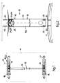
- the number 10 denotes the supporting structure in its entirety for a top 11 of a table 12.
- the supporting structure 10 comprises substantially horizontal beam elements 13 associated at the ends with vertical uprights 14 which function as the legs of the table 12.
- Each beam element 13 and upright 14 consists of tubular profiles 15 advantageously made in a single piece and of metal.
- tubular profiles 15 in this case are rectangular in section, but the invention is applicable also in the case of tubular profiles 15 with a different section, such as for example round, elliptical, polygonal or otherwise.
- the beam elements 13 are of the telescopic type, which allows the uprights 14 to be positioned at a variable distance according to the length and/or arrangement of the tops 11.
- the supporting structure also comprises plates 16 on which the top 11 rests and is associated; the plates 16 are attached above, and bases 17 are attached below, each upright 14.
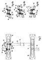
- the beam elements 13 and the uprights 14 are constrained together by means of screw elements 18, which can be coupled inside the corresponding screw seatings 19 provided in appropriate assembly elements 20 suitable to be inserted and clamped to the ends of the tubular profiles 15.
- the association between two tubular profiles 15, constituting respectively a beam element 13 and an upright 14, is obtained by inserting and clamping an assembly element 20 on a first tubular profile 15a in correspondence with one end, while the second tubular profile 15b is provided with through holes 21 into which screw elements 18 are inserted, the screw elements 18 also being inserted into the screw seatings 19 of the assembly element 20.
- the assembly elements 20 are inserted at the ends of the beam elements 13, and housed substantially in a retracted position inside, while the through holes 21 are made on the uprights 14.
- the assembly elements 20 may have different shapes and a different number of screw seatings 19 according to the type of assembly to be made, the geometry of the tubular profiles 15 and/or other specific requirements.
- the screw seatings 19 are made in a single piece on the assembly elements 20.
- the screw seatings 19 are defined by threaded inserts 50 which can be associated with the assembly elements 20 in correspondence with specific housings 43 and communicating with the outside of the relative assembly element 20 by means of channels 44 made in alignment with the through holes 21 on the upright 14 which is to be connected.
- the assembly elements 20 can be clamped and engaged to the tubular profiles 15 by means of ridges 22 which are inserted between coupling slits 23 made on the tubular profiles 15.
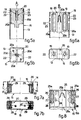
- Figs. 6a, 6b show an assembly element 20 for tubular profiles 15 with a substantially rectangular section comprising two distinct identical bodies 20a, arranged substantially symmetrical with respect to the tubular profile 15, on which the screw seatings 19 are made.
- an elastic fin 20b and a connection fin 20c made in a single piece with the bodies 20a.
- the assembly element 20 is inserted into the tubular profile 15 by compressing the two bodies 20a towards each other; the two bodies 20a elastically approach each other due to the presence of the elastic fin 20b, and thus the insertion operations are made easier.
- the assembly element 20 is positioned so as to bring the ridges 22 in correspondence with the coupling slits 23; the two bodies 20a are then released, and again take up their initial, distanced position and are clamped and engaged.
- the assembly element 20 is inserted into a tubular profile 15 with a square section; it comprises four elastic extensions 20d, substantially T-shaped, each of which with a relative ridge 22.
- the four elastic extensions 20d are reciprocally brought nearer to facilitate this operation, subsequently, they are released so as to insert the respective ridges 22 into corresponding coupling slits 23 made on the four sides of the tubular profile 15, causing the assembly element 20 to be clamped and engaged.
- This position of the elastic extensions 20d defines at the center the screw seating 19 for a single screw element 18 which, once screwed in, prevents the assembly element 20 from coming out.
- assembly elements 20 which comprise a greater or smaller number of elastic extensions 20d according to the section of the tubular profile 15 inside which they have to be inserted.
- the assembly element 20 is provided with two blind cavities 41 suitable to be arranged in alignment with mating through holes provided at the end of the first tubular profile 15a.
- blind cavities 41 are threaded inside and the assembly element 20 is clamped by means of screws.
- the assembly element 20 has a wider, abutment part 42 at the front, which is greater in size than the section of the first tubular profile 15a.
- the wider part 42 abuts against the perimeter edge 115a of the first tubular profile 15a, causing the correct positioning and centering of the assembly element 20 with respect to the profile 15a and preventing any further movements.
- a spacer element 25 is inserted in correspondence with the zone where the first and second tubular profile 15a, 15b connect.
- the spacer element 25 has the function of preventing the second tubular profile 15b from being crushed when the screw elements 18 are tightened.
- the spacer element 25 advantageously has through holes 24 which are aligned with the through holes 21 on the second profile 15b for the screw elements 18 to be inserted.
- the spacer element 25 has an identical conformation to that of the assembly element shown in Figs. 6a, 6b, consisting of two bodies 25a constrained by an elastic fin 25b and a connection fin 25c which facilitate the insertion of the spacer element 25 inside the tubular profiles 15.
- the spacer element 25 also includes ridges 26 which are inserted into coupling slits 27 on the tubular profiles 15, by means of which it can be clamped and engaged inside.
- the spacer element 25 has a pair of blind cavities 45 arranged in alignment with mating through holes provided on the second tubular profile 15b and inside which respective taper pins, suitable to clamp the spacer element 25, are suitable to be inserted and engaged.
- blind cavities 45 are threaded inside and cooperate with mating screws to clamp the spacer element 25.
- the spacer element 25 moreover, has at the lower part two housings 46 to position mating threaded inserts 51 inside which screw elements 40 are suitable to be screwed; the screw elements 40 can be inserted through channels 47 made lengthwise on the spacer element 25.
- the screw elements are used to attach the plate 16.
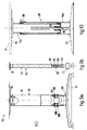
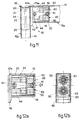
- the plate 16 in its assembled condition is arranged partly inside the upright 14 and aligned at the upper part with the upper surface of the beam element 13 (Fig. 11), which ensures a better support for the top 11 of the table 12.
- the plate 16 protrudes laterally with respect to the upright 14 and is arranged, on the side where it is associated with the beam element 13, inside a groove 42a made on the wider part 42 of the assembly element 20.
- the spacer element 25 is provided with a pair of attachment seatings 48 in correspondence with which a connection profile, not shown here, is suitable to be anchored; the connection profile is used when two beam elements 13 are associated together in a position opposite the upright 14.
- the bases 17 are constrained to the uprights 14 by means of a pair of assembly elements 20, inserted at the ends of each upright 14, each of which with its own screw seating 19 for respective screw elements 30.
- the assembly elements 20 include positioning shapings 31 cooperating with apertures 32 made on the uprights 14 by means of which the assembly elements 20 are arranged in the correct position inside the tubular profile 15 (Fig. 7a).
- the assembly element 20 to associate the base 17 with the upright 14 is made in a single piece and allows the height of the supporting structure 10 to be varied.
- the assembly element 20 is telescopically inserted inside the upright 14 and has two pairs of threaded bushes 29, or threaded holes, cooperating with a plurality of through holes 33 made on the sides of the upright 14.
- the assembly element 20 is made to slide inside the upright 14 so as to align the threaded bushes 29 with the desired through holes 33.
- the assembly element 20 is clamped into the desired position by screwing in appropriate screw elements 39 into the threaded bushes 29.
- the assembly element 20 is associated with the base 17, as in Fig. 2, by coupling screw elements (not shown here) into the screw seatings 19.
- an assembly element 20 equipped with lateral pins which can be elastically compressed and are suitable to be selectively inserted into mating through holes distributed over the height of the upright 14.
- the supporting structure 10 allows considerable possibilities of composition, and a plurality of tops 11 can be assembled with different arrangements or a single top 11 of considerable size can be supported.
- tops 11 aligned longitudinally are to be associated, or a single top 11 of a considerable size is to be supported, it is necessary to prepare a plurality of beam elements 13 arranged reciprocally parallel, but opposite the uprights 14.
- the beam elements 13 are associated off-axis with respect to the uprights 14 to allow the screw elements 18 to be screwed in from the front of the relative screw seatings 19 of the assembly elements 20 (Fig. 3).
- the beam elements 13 are arranged off-axis and possibly connected by means of suitable brackets 34.
- Fig. 10 shows a column element 35 employed for angled compositions and suitable to allow the height of the top 11 to be varied.
- the column element 35 comprises two tubular profiles 15c, 15d, telescopically associated to each other and on which the plate 16 and the base 17 are respectively attached.
- the height of the top 11 is varied by making the inner tubular profile 15c rotate in such a manner as to make the insert 37 slide on the supporting and adjusting screw 36.
- the inner tubular profile 15c is clamped with respect to the outer tubular profile 15d by means of a vice mechanism 38.
- At least the tubular profiles 15 defining the uprights 14 of the supporting structure 10 according to the invention are externally screened by covering elements 49 which can be associated and engaged.
- the covering element 49 shown has an open section substantially semi-elliptical, and is suitable to cover three sides of the tubular profile 15.
- the covering element 49 is made of an at least partly elastic material and can be applied by a partial deformation which allows it to be attached onto the edges of the tubular profile 15.
Landscapes
- Mutual Connection Of Rods And Tubes (AREA)
- Furniture Connections (AREA)
- Rod-Shaped Construction Members (AREA)
Abstract
Description
Claims (23)
- Supporting structure (10) for tops (11) of tables (12), desks or similar, comprising at least a substantially horizontal beam element (13) associated with vertical uprights (14), wherein both the beam element (13) and the uprights (14) consist of tubular profiles (15), the structure being characterised in that the tubular profiles (15a, 15b) are achieved in a single piece of a desired section and can be associated with each other by means of assembly elements (20) suitable to be inserted and clamped to the ends of at least one (15a) of the tubular profiles, each of the assembly elements (20) including at least an insertion seating (19) suitable to cooperate with corresponding attachment means (18), the attachment means (18) cooperating with insertion means (21) made in at least a second tubular profile (15b).
- Structure as in Claim 1, characterised in that the assembly elements (20) are arranged substantially in a retracted position inside the relative tubular profiles (15).
- Structure as in Claim 1, characterised in that the insertion means are through holes (21).
- Structure as in Claim 1, characterised in that the attachment means (18) are screws.
- Structure as in any claim hereinbefore, characterised in that the insertion seatings (19) are made in a single piece with the assembly elements (20).
- Structure as in any claim from 1 to 3 inclusive, characterised in that the insertion seatings (19) are defined by inserts (50) which can be associated with the assembly elements (20).
- Structure as in any claim hereinbefore, characterised in that the second tubular profile (15b) is internally associated with at least an anti-crushing spacer element (25) clamped in correspondence with the zone where the second tubular profile (15b) is associated with the first tubular profile (15a).
- Structure as in Claim 7, characterised in that the at least one spacer element (25) includes through holes (24) which can be associated with the insertion means (21) of the second tubular profile (15b).
- Structure as in any claim hereinbefore, characterised in that the assembly elements (20) and/or the spacer elements (25) include positioning and/or retaining means (22, 31, 26, 42) cooperating with the respective tubular profiles (15) into which they are inserted.
- Structure as in Claim 9, characterised in that the positioning and/or retaining means (22, 31, 26) engage and cooperate with respective means (23, 32, 27) made on the tubular profiles (15) to clamp the assembly elements (20) and/or spacer elements (25) onto the tubular profiles (15).
- Structure as in Claim 9, characterised in that the said positioning and/or retaining means (42) cooperate in abutment with the perimeter edge of the tubular profiles (15).
- Structure as in any claim hereinbefore, characterised in that the assembly elements (20) and/or the spacer elements (25) include elastic means (20b, 20d, 25b) suitable to allow them to contract and be inserted into the respective tubular profiles (15) and then subsequently expand to be clamped inside the tubular profiles (15).
- Structure as in any claim hereinbefore, characterised in that the assembly elements (20) and/or the spacer elements (25) include screw-in means (29) for mating screw means (39) to clamp the elements (20, 25) to the respective tubular profiles (15).
- Structure as in any claim hereinbefore, characterised in that the assembly elements (20) and/or the spacer elements (25) include cavities (41, 45) cooperating with mating through holes made on the respective tubular profiles (15), into which clamping pin means are inserted.
- Structure as in any claim hereinbefore, characterised in that the beam elements (13) and/or the uprights (14) consist of two or more tubular profiles (15) telescopically associated.
- Structure as in any claim hereinbefore, characterised in that it comprises plates (16) on which the top (11) rests and is associated, attached at the upper part to the uprights (14) or to the beam elements (13) by means of screw elements (40) which can be coupled with seatings (28, 51) made on the spacer elements (25) or the assembly elements (20).
- Structure as in any claim hereinbefore, characterised in that it comprises bases (17) associated at the lower part with the uprights (14) by means of assembly elements (20) inserted and clamped therein.
- Structure as in Claim 12, characterised in that the assembly elements (20) are telescopically constrained to the uprights (14) and include a plurality of association positions with respect thereto.
- Structure as in any claim hereinbefore, characterised in that it provides for two or more beam elements (13) to be associated to the same upright (14) in an off-axis position with respect to the upright (14).
- Structure as in any claim hereinbefore, characterised in that it comprises assembly profiles (34) cooperating with the assembly elements (20) in the association with the beam elements (13) with the uprights (14).
- Structure as in any claim hereinbefore, characterised in that it comprises covering elements (49) which can be associated and engaged at least with the uprights (14).
- Structure as in any claim hereinbefore, characterised in that it comprises column elements (35) to support the top (11) in angled compositions, the column elements (35) comprising two tubular profiles (15b, 15c) telescopically associated with each other, the inner tubular profile (15c) being constrained rotatable with respect to supporting and adjusting screw means (36) solid with the outer tubular profile (15d) to define the height of the top (11).
- Structure as in Claim 22, characterised in that the inner tubular profile (15c) can be clamped with respect to the outer tubular profile (15d) by means of vice means (38).
Applications Claiming Priority (2)
| Application Number | Priority Date | Filing Date | Title |
|---|---|---|---|
| ITUD980066 | 1998-04-17 | ||
| ITUD980066 IT1299780B1 (en) | 1998-04-17 | 1998-04-17 | SUPPORT STRUCTURE FOR TABLE TOP, DESKS OR SIMILAR |
Publications (2)
| Publication Number | Publication Date |
|---|---|
| EP0956791A2 true EP0956791A2 (en) | 1999-11-17 |
| EP0956791A3 EP0956791A3 (en) | 2000-08-02 |
Family
ID=11422656
Family Applications (1)
| Application Number | Title | Priority Date | Filing Date |
|---|---|---|---|
| EP99107269A Pending EP0956791A3 (en) | 1998-04-17 | 1999-04-14 | Supporting structure for tops of tables, desks or similar |
Country Status (2)
| Country | Link |
|---|---|
| EP (1) | EP0956791A3 (en) |
| IT (1) | IT1299780B1 (en) |
Cited By (1)
| Publication number | Priority date | Publication date | Assignee | Title |
|---|---|---|---|---|
| WO2016166107A1 (en) * | 2015-04-16 | 2016-10-20 | Dewertokin Gmbh | Frame for a table or desk |
Family Cites Families (2)
| Publication number | Priority date | Publication date | Assignee | Title |
|---|---|---|---|---|
| DE3805592A1 (en) * | 1988-02-23 | 1989-08-31 | Gesika Bueromoebelwerk Gmbh | Connection for frame parts of furniture, in particular office furniture |
| FR2719982B3 (en) * | 1994-05-17 | 1996-07-05 | Inventions Rech Equip Ste Ind | Table with removable base. |
-
1998
- 1998-04-17 IT ITUD980066 patent/IT1299780B1/en active IP Right Grant
-
1999
- 1999-04-14 EP EP99107269A patent/EP0956791A3/en active Pending
Cited By (2)
| Publication number | Priority date | Publication date | Assignee | Title |
|---|---|---|---|---|
| WO2016166107A1 (en) * | 2015-04-16 | 2016-10-20 | Dewertokin Gmbh | Frame for a table or desk |
| US11089864B2 (en) | 2015-04-16 | 2021-08-17 | Dewertokin Technology Group Co., Ltd. | Frame for a table or desk |
Also Published As
| Publication number | Publication date |
|---|---|
| EP0956791A3 (en) | 2000-08-02 |
| IT1299780B1 (en) | 2000-04-04 |
| ITUD980066A1 (en) | 1999-10-18 |
Similar Documents
| Publication | Publication Date | Title |
|---|---|---|
| EP3282892B1 (en) | Frame for a table or desk | |
| US4572574A (en) | Collapsible table structure with interconnected bench seats | |
| US20120005980A1 (en) | Structural Members For Forming Various Composite Structures | |
| DE19733435C2 (en) | Office table | |
| WO1996028067A1 (en) | Kit for a shelf unit | |
| EP0830825A2 (en) | Linkage element for a furniture frame, assembling kit for a furniture support and construction set for assembling a piece of furniture | |
| WO2021105197A1 (en) | Furniture kit | |
| EP4064940A1 (en) | Crossmember, crossmember set, and furniture kit | |
| DE102004002394A1 (en) | Furniture e.g. room divider, assembling set, has intermediate profiles, each arranged between two square plate components for supporting components, and screws that are inserted into recesses of outer surfaces of components | |
| DE102005060277B3 (en) | Platform with column connection | |
| DE102010016107B4 (en) | Portable stage pedestal element | |
| DE4301290C2 (en) | Demountable shelving and cupboard system | |
| EP1869331B1 (en) | Coupling system for rapidly and detachably interconnecting furniture elements requiring little storage space, and corresponding seats | |
| DE3918180C2 (en) | ||
| EP0275001B1 (en) | Container for coach work parts | |
| DE102021107152B4 (en) | shelving system | |
| DE10328408B4 (en) | Corner connector for a control cabinet | |
| DE69717547T2 (en) | Improvements to or in relation to furniture | |
| EP0283433B1 (en) | Emergency bed system | |
| US20240035270A1 (en) | A connector | |
| EP0782654A2 (en) | Connection system, in particular for constructing accommodation units and assembled furniture | |
| EP1142509B1 (en) | Rack | |
| WO1998007350A2 (en) | Table | |
| DE9116710U1 (en) | Detachable furniture | |
| DE202022107179U1 (en) | Base and table |
Legal Events
| Date | Code | Title | Description |
|---|---|---|---|
| PUAI | Public reference made under article 153(3) epc to a published international application that has entered the european phase |
Free format text: ORIGINAL CODE: 0009012 |
|
| AK | Designated contracting states |
Kind code of ref document: A2 Designated state(s): AT BE CH DE ES FR GB IT LI LU NL PT SE |
|
| AX | Request for extension of the european patent |
Free format text: AL;LT;LV;MK;RO;SI |
|
| PUAL | Search report despatched |
Free format text: ORIGINAL CODE: 0009013 |
|
| AK | Designated contracting states |
Kind code of ref document: A3 Designated state(s): AT BE CH CY DE DK ES FI FR GB GR IE IT LI LU MC NL PT SE |
|
| AX | Request for extension of the european patent |
Free format text: AL;LT;LV;MK;RO;SI |
|
| RIC1 | Information provided on ipc code assigned before grant |
Free format text: 7A 47B 13/06 A, 7A 47B 17/00 B |
|
| 17P | Request for examination filed |
Effective date: 20010201 |
|
| AKX | Designation fees paid |
Free format text: AT BE CH DE ES FR GB IT LI LU NL PT SE |
|
| STAA | Information on the status of an ep patent application or granted ep patent |
Free format text: STATUS: EXAMINATION IS IN PROGRESS |
|
| 17Q | First examination report despatched |
Effective date: 20021113 |