EP3273785B1 - Vorrichtung und verfahren zum brühen von geschlachtetem geflügel - Google Patents
Vorrichtung und verfahren zum brühen von geschlachtetem geflügel Download PDFInfo
- Publication number
- EP3273785B1 EP3273785B1 EP16712301.7A EP16712301A EP3273785B1 EP 3273785 B1 EP3273785 B1 EP 3273785B1 EP 16712301 A EP16712301 A EP 16712301A EP 3273785 B1 EP3273785 B1 EP 3273785B1
- Authority
- EP
- European Patent Office
- Prior art keywords
- channel
- scalding
- transport
- poultry
- medium
- Prior art date
- Legal status (The legal status is an assumption and is not a legal conclusion. Google has not performed a legal analysis and makes no representation as to the accuracy of the status listed.)
- Active
Links
Images


Classifications
-
- A—HUMAN NECESSITIES
- A22—BUTCHERING; MEAT TREATMENT; PROCESSING POULTRY OR FISH
- A22C—PROCESSING MEAT, POULTRY, OR FISH
- A22C21/00—Processing poultry
- A22C21/04—Scalding, singeing, waxing, or dewaxing poultry
-
- A—HUMAN NECESSITIES
- A22—BUTCHERING; MEAT TREATMENT; PROCESSING POULTRY OR FISH
- A22B—SLAUGHTERING
- A22B5/00—Accessories for use during or after slaughtering
- A22B5/08—Scalding; Scraping; Dehairing; Singeing
-
- A—HUMAN NECESSITIES
- A22—BUTCHERING; MEAT TREATMENT; PROCESSING POULTRY OR FISH
- A22C—PROCESSING MEAT, POULTRY, OR FISH
- A22C21/00—Processing poultry
- A22C21/0053—Transferring or conveying devices for poultry
-
- Y—GENERAL TAGGING OF NEW TECHNOLOGICAL DEVELOPMENTS; GENERAL TAGGING OF CROSS-SECTIONAL TECHNOLOGIES SPANNING OVER SEVERAL SECTIONS OF THE IPC; TECHNICAL SUBJECTS COVERED BY FORMER USPC CROSS-REFERENCE ART COLLECTIONS [XRACs] AND DIGESTS
- Y02—TECHNOLOGIES OR APPLICATIONS FOR MITIGATION OR ADAPTATION AGAINST CLIMATE CHANGE
- Y02A—TECHNOLOGIES FOR ADAPTATION TO CLIMATE CHANGE
- Y02A40/00—Adaptation technologies in agriculture, forestry, livestock or agroalimentary production
- Y02A40/90—Adaptation technologies in agriculture, forestry, livestock or agroalimentary production in food processing or handling, e.g. food conservation
Definitions
- the invention relates to a device, designed and set up for brewing slaughtered poultry, comprising an elongated, upwardly open brewing tank for receiving and holding a brewing medium with at least one transport path for the poultry, each transport path in its longitudinal extent to at least one Part of the length of the transport path extending separating element is adjacent, arranged above the brewing tank transport for transporting the suspended on the feet of poultry along the transport path in the transport direction T, a control and regulating unit for controlling the Brühmediums, means for generating a turbulence and / or flow of the Brühmediums and a filter device for cleaning the Brühmediums.
- the invention relates to a method for brewing slaughtered poultry, comprising the steps of: transporting the poultry G on the feet by a brewing medium at least partially filled brewing tank by means of a transport along a transport path in the transport direction T, tempering the brewing medium by means of a control and control unit, cleaning the brewing medium by means of a filter device, and swirling the brewing medium by means for generating a swirling and / or flow.
- Such devices and methods are used in the poultry processing industry (see, for example, the document NL 1 009 188 C2 ) to prepare the plumage of the poultry, which include chickens, turkeys, ducks, geese and other food-processing birds and waterfowl, for the actual defoliation of the feathers by the springs through the heated / heated brewing medium quasi softened or dissolved in the area of quills.
- the poultry is exposed to a warm or hot steam or, as in the generic device, transported through a brewing medium filled brewing tank.
- the brewing medium usually water, can be enriched by additionally introduced air or additives in the brewing medium.
- a brewing device with the features of the preamble of claim 1 is known.
- the brewing tank is divided by a partition in two transport routes.
- upwardly directed nozzles are arranged in the region of the brewing tank bottom as means for generating turbulence and / or flow of the brewing medium.
- By means of these nozzles is a vertically upward, directed beyond the poultry out stream of Brühmediums generated.
- Guiding means in the upper area of the brewing tank ensure that this stream is deflected and directed downwards in the direction of the poultry.
- the partition wall as a heat exchanger within the brewing tank is used in the known device as a control and regulating unit for tempering the brewing medium.
- the transported along the transport lines poultry is directly exposed to the radiant heat of the heat exchanger when the poultry is transported past the partition. This can lead to overheating of the poultry and thus damage to the skin and the meat.
- the brewing medium is in particular also stirred up on the surface of the brewing medium in the brewing tank, which leads to a heat loss on the surface of the brewing medium, which must be compensated by the supply of additional energy.
- the nozzles as a means for generating the flow of Brühmediums anyway require a high energy input, especially since a plurality of nozzles along the transport path is necessary to produce over the entire length of the required flow.
- the device according to EP 1 787 519 A difficult to clean.
- the invention is therefore an object of the invention to provide a cost in manufacturing and operation and easy to use device for brewing slaughtered poultry.
- the object continues to be to propose a corresponding method.
- each separating element arranged two spaced apart and upwardly extending partition walls extending from the bottom wall of the brewing tank to form a channel open upwards and to the end faces, and a swirling body as means for generating the swirling and / or within the channel in the area of openings in each partition wall facing a transport path
- Flow of the brewing medium is arranged, which is driven in rotation by means of a horizontally directed and transversely to the transport direction T of the poultry running drive shaft.
- the formed by the partitions and at least partially shielded by the or each transport channel channel is open both upwards and to the two end faces, so that the brewing medium within the entire brewing tank - in the rest state of Verwirbelungs stressess - has a uniform level, ie within the channel has the same level as in the transport routes because there is an open connection between the or each transport route and the or each channel. In the area of the openings in the partitions, there is also a connection between the transport path and the channel for the passage of the brewing medium.
- the brewing medium can be sucked by the rotation of the swirling body from the bottom of the transport path through the apertures, whereby an overpressure arises within the channel over its entire length.
- sucking the brewing medium into the channel the poultry can be assisted in staying in a substantially vertical orientation to prevent the bird from floating. Due to the overpressure within the channel, the brewing medium is pushed out of the channel at the open end sides and / or at the open top side, so that the poultry is optimally exposed to the brewing medium.
- a particularly preferred development of the invention is characterized in that at least two parallel transport paths are formed in the brewing tank, which in their longitudinal extent through the separating element at least partially separated from each other.
- the or each partition wall of the separating element is at least at the reversal point of the transport when changing from a first transport path into the adjacent transport path spaced from the outer wall of the brewing tank designed to allow the poultry to pass or change from one transport route to the next transport route.
- the duplication of the transport route extends the flock of the poultry in the brewing medium without reducing the output of finished brewed poultry at the exit of the device.
- more than two parallel transport paths are formed in the brewing tank, wherein two adjacent transport sections are at least partially separated from each other by a separating element.
- a particularly expedient embodiment of the invention is characterized in that the swirling body comprises at least one impeller, propeller or the like.
- a vortex water turbine as a swirling body which has a very high pumping capacity at a low number of revolutions (e.g., 300 rpm) and thus provides for energy efficient generation of turbulence and / or flow.
- a particular advantage of the embodiment according to the invention lies in the fact that due to the high pumping capacity a single pumping station, preferably centrally arranged, is sufficient to allow sufficient turbulence / flow within the device with a length of up to 10 m produce.
- the swirl body comprises at least two impellers, propellers or the like, which are arranged on the same drive shaft.
- a plurality of swirling bodies can be arranged on the same drive shaft, so that brewing devices with up to eight transport routes, preferably with two to four transport routes, via this a central pumping station by the drive shaft, the thereon arranged Verwirbelungs moments and the drive for the drive shaft is formed, can be operated particularly cost-effectively.
- a preferred embodiment of the invention is characterized in that at both ends of each channel in the region of the partition walls in each case at least one Deflection element for deflecting the flowing at the end faces of the channel Brühmediums is arranged in the transport direction T of the poultry.
- the deflecting element is in each case arranged and aligned on the end faces such that the brewing medium flowing out of the channel is directed only to one transport path. Due to the deflecting elements, the brewing medium in each case flows in the transport direction T into the transport sections. In other words, the poultry can always be transported with the flow direction of the brewing medium in the transport route, whereby the floating of the poultry is effectively prevented.
- An advantageous embodiment is characterized in that in the region of the upwardly open channel baffle elements for deflecting the upward flowing out of the channel brewing medium are arranged downwards in the direction of the bird.
- the baffle elements extend substantially over the entire length of the channel and are optionally designed and arranged for deflecting the brewing medium from the channel to the one and / or to the other transport path.
- one or more baffle elements are provided, which are arranged on the upper edge of the partitions and deflect the upward flowing out of the channel brewing medium, depending on the design and arrangement of the baffle elements either to one side and / or the other side of the channel, so that the brewing medium flows either in one of the two transport routes or in both transport routes, so that the poultry is acted upon over the entire length of the transport paths from above with a Brühmediumstrom.
- An expedient development is characterized in that the two partitions forming a channel are designed to be pivotable for maintenance and / or cleaning purposes. As a result, the maintenance of the device and in particular the cleaning of the brewing tank are substantially simplified.
- each partition in the region of the bottom wall of the brewing tank is provided with a hinge or the like for pivoting the partition walls from a parallel operating position into a V-shaped maintenance and / or cleaning position and back.
- the partitions are hinged to the bottom of the brewing tank.
- other pivotal movement enabling components can be used.
- the cleaning of the channel is particularly easy to carry out.
- a preferred embodiment is characterized in that each turbulence body is shielded in the region of the openings with respect to the transport paths by a protective element permeable to the brewing medium. As a result, the risk of a collision of the poultry with a swirling body during transport along the transport route is effectively prevented.
- At least one heat source of the control and regulating unit for tempering the brewing medium is disposed within the channel.
- the poultry is opposite the heat source, e.g. a heat exchanger of the control unit shielded, causing damage to the poultry are avoided.
- the brewing medium heated / heated in the channel is mixed with the brewing medium in the brewing tank prior to impacting the poultry prior to encountering the poultry, thereby providing even heat distribution for a poultry-sparing yet effective brewing operation to improve quality.
- the object is also achieved by a method according to claim 13, characterized in that the brewing medium in one of the or each transport path at least partially shielded channel by means of a Verwirbelungs stresses which is driven to rotate about a horizontally oriented and transverse to the transport direction T drive shaft, and then swirled again the or each transport line is supplied.
- the brewing medium is sucked from the or each transport path by means of the swirling body in the channel and thereby generates an overpressure in the channel, which ensures that the brewing medium at the ends and / or at the top of the channel exits and is returned to the transport routes ,
- An advantageous development is characterized in that the brewing medium emerging from the end faces of the channel is deflected by deflection elements such that the emerging brewing medium flows in the transport direction T of the bird G.
- the emerging from the top of the channel brewing medium is deflected by baffles such that the hanging poultry G is acted upon by the exiting brewing medium from top to bottom with this.
- a preferred variant provides that the poultry G is transported along the transport routes through a brewing tank filled only slightly with brewing medium, so that the poultry G does not dive at all or only slightly into the brewing medium and completely or predominantly through the brewing medium flowing out of the channel above is acted upon with this. As a result, the effect of the floating of the poultry is completely avoided and the springs are applied against the direction of growth directly in the quills with the Brühmedium.
- An alternative variant provides that the poultry G is transported along the transport routes through a brewing tank completely filled with brewing medium, so that the poultry G is completely immersed in the brewing medium and through the standing in the transport routes and through the top and / or on the front sides from the channel flowing Brühmedium acted upon with this. Due to the high level of Brühmediums with only a slight turbulence of the surface of the Brühmediums the heat loss from the Brühmedium is reduced to the environment relevant.
- the brewing medium within the channel is tempered by the control unit, wherein the tempered in the channel brewing medium when flowing out of the channel with the Brühedium located in the transport paths and then these Brühmediummischung meets the poultry G.
- a particularly advantageous embodiment provides that the method is carried out with a device according to one of claims 1 to 12
- the apparatus shown in the drawing is used to brew heads over down-hanging chickens that are transported within the brewing tank at a very high level of the brewing medium, such that the chickens are completely below the surface of the brewing medium, so that the chickens by standing in the transport routes Brühmedium and additionally be acted upon by the brewing medium flowing at the end faces and at the top of the channel.
- the level of the brewing medium may also be lower, such that the chickens are not or only partially immersed in the brewing medium, for example up to the neck, so that the chickens are acted upon exclusively or predominantly by the brewing medium flowing from the top of the channel.
- the invention is also applicable to turkeys, ducks, geese and other birds and waterfowl.
- a device 10 which is designed and set up for brewing slaughtered poultry G.
- the device 10 comprises an elongated, upwardly open brewing tank 11 for receiving and holding a brewing medium with at least one transport path 12.1 for the poultry G, wherein each transport path 12.1 in its longitudinal extent to a at least over a part of the length of the transport path 12.1 extending separating element 13 borders.
- the device 10 comprises a arranged above the brewing tank 11 transport 14 for transporting the suspended on the feet of poultry G along the transport path 12.1 in the transport direction T and a control and regulating unit 15 for tempering the brewing medium.
- the device 10 comprises means 16 for generating a turbulence and / or flow of the brewing medium and a filter device 35 for cleaning the brewing medium.
- This device 10 is characterized in that each separating element 13 two spaced apart and from the bottom wall 17 of the brewing tank 11 upwardly extending partitions 18,19 to form an upwardly and to the end faces S K1 , S K2 towards open channel 20, and within the channel 20 in the region of openings 21, 22 in each transport path 12.1 facing partition wall 18, 19, a swirling body 23 is arranged as means 16 for generating the swirling and / or flow of the brewing medium by means of a horizontally directed and transverse to the transport direction T of the poultry G extending drive shaft 24 is driven in rotation.
- a single swirl body 23 can extend over the entire channel width, so that the single swirl body 23 extends into the area of both openings 21, 22. But it can also be arranged in the region of each opening 21, 22, a separate Verwirbelungs stresses 23.
- the brewing tank 11 is a trough-like body which is bounded below by the bottom wall 17 and laterally by the side walls 25, 26.
- the brewing tank 11 extends in the transport direction T in the longitudinal direction.
- the relative to the side walls 25, 26 significantly shorter end walls 27, 28 limit the brewing tank 11 to form the receiving volume for the brewing medium, so that this can be recorded and held, so can be stored.
- the brewing medium may be water or another fluid, for example water enriched with at least one additive or the like.
- the bottom wall 17 may be horizontal and level or, as in the FIG. 1 represented, also be V-shaped.
- the brewing tank 11 may be formed in one piece or modular or segment-like and has in the illustrated variant a total length of preferably about 8m. The dimensions of the brewing tank 11 may vary.
- the transport means 14 is an overhead conveyor designed as an overhead conveyor, on which the poultry G with its feet in shackles 29 hanging along the transport routes 12.1, 12.2 is promoted.
- the overhead conveyor or its conveyor rail is guided meandering, such that the conveyor rail is deflected at the input and output opposite end face S B2 by 180 ° to allow the poultry G to change from one transport section 12.1 in the other transport path 12.2.
- the separating element 13 at least on the end face S B2 facing side spaced from the end wall 27 of the brewing tank 11 is formed.
- devices 10 are also formed in which more than two parallel transport paths 12.1, 12.2,... 12.n are formed in the brewing tank 11. In this case there are two adjacent transport routes 12.1, 12.2, .n each separated at least partially by a separating element 13 from each other.
- the overhead conveyor or its conveyor rail is guided according to meandering.
- each separating element 13 is also formed on the end face S B1 in the region of the input and output spaced from the end wall 28 of the brewing tank 11.
- the swirling body 23 is arranged centrally in the illustrated embodiment.
- the or each swirling body 23 is arranged approximately centrally with respect to the length of the transport paths 12.1, 12.2,... 12.n centrally on a single drive shaft 24, which can be driven to rotate by means of a single drive 30.
- the drive shaft 24 is mounted in the side walls 25, 26 of the brewing tank 11 and optionally additionally in the partitions 18, 19 of the separating element 13.
- the swirling body 23 comprises at least one impeller or a propeller or a turbine or another swirling element.
- the swirl body 23 comprises at least one vortex water turbine, which is arranged between the two partitions 18, 19 in the region of the openings 21, 22 and has a very high pumping volume at a low number of revolutions (eg of 300 rpm).
- a vortex water turbine this can have one rotor blade or two rotor blades. In the case where two rotor blades are provided, they may be separated from each other by a partition wall or the like. If the vortex water turbine has only one rotor blade, which then only faces a dividing wall 18, 19, only brewing medium is sucked out of the transport path 12.1, 12.2,... 12.n, to which the rotor blade is directed.
- the or each Verwirbelungsêtêt stresses 23 may be arranged off-center and in particular on the end faces S K1 , S K2 of the channel 20. In the event that the swirling body 23 is a vortex water turbine, this can preferably be arranged at the input side E and output A facing end face S K1 of the channel 20 in this.
- the swirling body 23 may have an impeller or a propeller in a partition wall 18, 19 or in both partitions 18, 19 in the region of the openings 21, 22.
- the swirling body 23 may have an impeller or a propeller in a partition wall 18, 19 or in both partitions 18, 19 in the region of the openings 21, 22.
- a plurality of brewing tanks 11 may be arranged next to one another as modules, so that a drive shaft 24 extends through a plurality of brewing tanks 11 and is supported therein to support and drive all the swirling bodies 23 of an arrangement consisting of two or more brewing tanks 11.
- each channel 20 in the region of the partitions 18, 19 each have at least one deflecting element 31, 32 for deflecting the brewing medium flowing from the channel 20 at the end faces S K1 , S K2 in the transport direction T of the poultry G arranged.
- a simple embodiment of a deflecting element 31 is shown, which is arranged at the end of the U-shaped channel 20 on a partition wall 18, 19 and deflects the current generated by the Verwirbelungs stresses 23 of Brühmediums such that the brewing medium in the transport paths 12.1, 12.2 ,. ... 12.n follows the transport direction T of the poultry G in the horizontal direction.
- the deflection can also be done by other, for example, to the partitions 18,19 separate deflection or the like.
- baffle elements 33 for deflecting the upward flowing from the open channel 20 Brühmediums down in the direction of the bird G are arranged.
- the baffles 33 may extend over a portion of the length of the channel 20 or over the entire length.
- Each baffle element 33 may be configured and arranged to divert the brewing media to one side (e.g., transport path 12.1) or to the other side (e.g., transport path 12.2) or both sides (e.g., transport routes 12.1 and 12.2).
- the baffles 33 are preferably simple baffles or the like having a flow-supporting, rounded inner surface disposed on one of the partitions 18, 19.
- partitions 18, 19 form the channel 20, which is preferably U-shaped.
- the partition walls 18, 19 extend from the bottom wall 17 of the Brewing tanks 11 upwards, and preferably to below the upper edge of the side walls 25, 26 of the brewing tank 11, so that the upper edges of the partition walls 18, 19 at maximum level of the brewing tank 11 with brewing medium below the surface O of the brewing medium are (see, eg FIGS. 6 and 7 ).
- the dividing walls 18, 19 are arranged spaced apart from one another in parallel. They can be firmly connected to the brewing tank 11.
- the partitions 18, 19 are designed to be pivotable, in particular for maintenance and cleaning purposes.
- each partition 18, 19 provided in the region of the bottom wall 17 of the brewing tank 11 with a hinge 36 or the like for pivoting the partitions 18, 19 from a parallel operating position into a V-shaped maintenance and / or cleaning position and back.
- the partition walls 18, 19 are fixed to the bottom wall 17 by means of a hinge 36 or the like.
- the partitions 18, 19 can be fixed at least in its operating position.
- only one of the partitions 18,19 is pivotable.
- only parts of the partition walls 18, 19 can be designed and arranged to be pivotable or foldable in their horizontal and / or vertical extent.
- the swirl body 23 is disposed within the channel 20.
- a simple protective grid is shown, which prevents the poultry G can come into direct contact with the swirling body 23.
- the protective element 34 is formed and arranged to also shield the drive shaft 24 extending transversely through the transport paths 12.1, 12.2,... 12.n and the or each channel 20 from the poultry G.
- the control and regulating unit 15 for tempering the brewing medium may be arranged at any position within the device 10.
- the or each heat source of the control unit 15 is disposed within the channel 20.
- a sensor or the like of the control unit 15 is preferably disposed within the channel 20.
- the filter device 35 for filtering the brewing medium and / or for controlling and regulating the level of the brewing medium within the brewing tank 11, and thus within the transport sections 12.1, 12.2, ... 12.n and the channels 20 can also be located at any position within the device 10 may be arranged.
- the filter device 35 is arranged on the end face S B2 .
- the filter device 35 can also be arranged on the end face S B1 , specifically in the region of the end face S K1 of the channel 20, that is to say at the end of the separating element 13 between the conveying rails of the transport means 14.
- the hanging on the feet of poultry G is - preferably with the back to the partition wall 18, 19 facing - by a brewing medium at least partially filled brewing tank 11 by means of a transport 14 along a transport path 12.1, 12.2, .... 12.n in the transport direction T. transported.
- the brewing medium is tempered to the desired brewing temperature by means of a control and regulation unit 15 and this brewing temperature is also controlled and regulated during operation.
- the brewing medium is cleaned by a filter device 35.
- the brewing medium is swirled by a means 16 for generating a turbulence and / or flow.
- the method is characterized in that the brewing medium in one of the or each transport section 12.1, 12.2, .... 12.n at least partially shielded channel 20 by means of a Verwirbelungs stresses 23, which extends around a horizontally oriented and transverse to the transport direction T.
- Drive shaft 24 is driven to rotate, swirled and then the or each transport path 12.1, 12.2, .... 12.n is supplied.
- the brewing medium is preferably sucked out of the or each transport path 12.1, 12.2, ... 12.n by means of the swirling body 23 into the channel 20, whereby an overpressure is generated in the channel 20, which ensures that the brewing medium at the end faces S K1 , S K2 and / or emerges at the top of the channel 20 and again the transport paths 12.1, 12.2, .... 12.n is supplied. That from the end faces S K1 , S K2 of the channel 20 emerging brewing medium is preferably deflected by deflecting elements 31, 32 such that the emerging brewing medium in the transport direction T of the poultry G flows. In other words, we always transport the poultry G with the flow direction of the brewing medium.
- the upward emerging from the channel 20 brewing medium can be deflected by baffles 33 such that the hanging poultry G is acted upon by the exiting brewing medium against the spring growth from top to bottom with this.
- the poultry G along the transport routes 12.1, 12.2, .... 12.n transported by a scalding medium only slightly filled with brewing tank 11, so that the poultry G is not or only slightly immersed in the brewing medium and completely or is mainly acted upon by the above from the channel 20 flowing Brühmedium with this.
- the poultry G depends in the transport routes, but does not touch the brewing medium or dives only slightly, for example, only up to the neck, in the brewing medium to avoid the resulting during transport through the brewing medium retention force or very low hold.
- the brewing medium has only such a level in the brewing tank 11 that it is sucked into the channel 20 by means of the swirling body 23, in particular by means of the vortex water turbine, and returned from the latter via the baffle elements 33 from top to bottom via the poultry G. In this case, brewing takes place essentially through the brewing medium flowing out of the channel 20 at the top.
- the poultry G along the transport routes 12.1, 12.2, .... 12.n transported by a fully filled with brewing medium brewing tank 11 so that the poultry G is completely immersed in the brewing medium and by the in the transport routes 12.1, 12.2 ,. .. 12.n standing and by the above and / or on the end faces of the channel 20 flowing Brühmedium charged with this (see, eg FIGS. 6 and 7 ).
- the brewing medium flowing out of the channel 20 causes a turbulence of the brewing medium in the transport sections 12.1, 12.2,..., 12.n, so that a particularly effective admission of the bird G with brewing medium is ensured.
- the brewing medium is tempered within the channel 20 by the control and regulating unit 15, wherein the brewing medium tempered in the channel 20 mixes when flowing out of the channel 20 with the brewing medium located in the transport sections 12.1, 12.2, ... 12.n and this brew medium mix then meets the poultry G.
- FIG. 9 is schematically indicated what effect the swirling body 23 and in particular the vortex water turbine, namely a turbulence of the brewing medium such that the brewing medium is directed within the channel 20 to generate an overpressure evenly in all directions.
- the device 10 according to the invention is particularly suitable for carrying out the method.
Landscapes
- Life Sciences & Earth Sciences (AREA)
- Engineering & Computer Science (AREA)
- Food Science & Technology (AREA)
- Wood Science & Technology (AREA)
- Zoology (AREA)
- Processing Of Meat And Fish (AREA)
- Housing For Livestock And Birds (AREA)
- Catching Or Destruction (AREA)
Description
- Die Erfindung betrifft eine Vorrichtung, ausgebildet und eingerichtet zum Brühen von geschlachtetem Geflügel, umfassend einen länglichen, nach oben offenen Brühtank zur Aufnahme und zum Halten eines Brühmediums mit mindestens einer Transportstrecke für das Geflügel, wobei jede Transportstrecke in ihrer Längserstreckung an ein sich mindestens über einen Teil der Länge der Transportstrecke erstreckendes Trennelement grenzt, ein oberhalb des Brühtanks angeordnetes Transportmittel zum Transport des an den Füßen aufgehängten Geflügels entlang der Transportstrecke in Transportrichtung T, eine Steuer- und Regeleinheit zum Temperieren des Brühmediums, Mittel zum Erzeugen einer Verwirbelung und/oder Strömung des Brühmediums sowie eine Filtereinrichtung zum Reinigen des Brühmediums.
Des Weiteren betrifft die Erfindung ein Verfahren zum Brühen von geschlachtetem Geflügel, mit den Schritten: Transportieren des Geflügels G an den Füßen hängend durch einen mit Brühmedium mindestens teilweise gefüllten Brühtank mittels eines Transportmittels entlang einer Transportstrecke in Transportrichtung T, Temperieren des Brühmediums mittels einer Steuer- und Regeleinheit, Reinigen des Brühmediums mittels einer Filtereinrichtung, und Verwirbeln des Brühmediums mittels eines Mittels zum Erzeugen einer Verwirbelung und/oder Strömung.
Solche Vorrichtungen und Verfahren kommen in der Geflügel verarbeitenden Industrie zum Einsatz (vgl. z.B. das DokumentNL 1 009 188 C2 - Aus der
EP 1 787 519 A1 ist eine Brühvorrichtung mit den Merkmalen des Oberbegriffes des Anspruches 1 bekannt. Bei dieser Vorrichtung ist der Brühtank durch eine Trennwand in zwei Transportstrecken geteilt. Zu beiden Seiten der Trennwand sind im Bereich des Brühtankbodens nach oben gerichtete Düsen als Mittel zum Erzeugen einer Verwirbelung und/oder Strömung des Brühmediums angeordnet. Mittels dieser Düsen ist ein vertikal nach oben, über das Geflügel hinaus gerichteter Strom des Brühmediums erzeugbar. Führungsmittel im oberen Bereich des Brühtanks sorgen dafür, dass dieser Strom umgelenkt und nach unten in Richtung des Geflügels gerichtet wird. Die Trennwand als Wärmetauscher innerhalb des Brühtanks dient bei der bekannten Vorrichtung als Steuer- und Regeleinheit zum Temperieren des Brühmediums. Damit ist das entlang der Transportstrecken transportierte Geflügel unmittelbar der Strahlungswärme des Wärmetauschers ausgesetzt, wenn das Geflügel an der Trennwand vorbei transportiert wird. Das kann zu einer Überhitzung des Geflügels und damit zur Beschädigung der Haut und des Fleisches führen. Durch das Erzeugen einer Strömung des Brühmediums mittels der Düsen wird das Brühmedium insbesondere auch an der Oberfläche des Brühmediums im Brühtank aufgewühlt, wodurch es zu einem Wärmeverlust an der Oberfläche des Brühmediums kommt, der durch die Zuführung zusätzlicher Energie kompensiert werden muss. Ein weiterer Nachteil besteht darin, dass die Düsen als Mittel zum Erzeugen der Strömung des Brühmediums ohnehin einen hohen Energieeinsatz erfordern, zumal eine Vielzahl von Düsen entlang der Transportstrecke notwendig ist, um über die gesamte Länge die erforderliche Strömung zu erzeugen. Im Übrigen ist die Vorrichtung gemäßEP 1 787 519 A nur schwer zu reinigen.
Der Erfindung liegt somit die Aufgabe zugrunde, eine in der Herstellung und im Betrieb kostengünstige sowie einfach zu handhabende Vorrichtung zum Brühen von geschlachtetem Geflügel zu schaffen. Die Aufgabe besteht weiterhin darin, ein entsprechendes Verfahren vorzuschlagen. - Diese Aufgabe wird durch die Vorrichtung gemäß Anspruch 1 dadurch gelöst, dass jedes Trennelement zwei beabstandet zueinander angeordnete und sich von der Bodenwand des Brühtanks nach oben erstreckende Trennwände zur Bildung eines nach oben und zu den Stirnseiten hin offenen Kanals umfasst, und innerhalb des Kanals im Bereich von Durchbrüchen in jeder einer Transportstrecke zugewandten Trennwand ein Verwirbelungskörper als Mittel zur Erzeugung der Verwirbelung und/oder Strömung des Brühmediums angeordnet ist, der mittels einer horizontal gerichteten und quer zur Transportrichtung T des Geflügels verlaufenden Antriebswelle rotierend antreibbar ist. Der durch die Trennwände gebildete und von der oder jeder Transportstrecke mindestens teilweise abgeschirmte Kanal ist sowohl nach oben als auch zu den beiden Stirnseiten offen, so dass das Brühmedium innerhalb des gesamten Brühtanks - im Ruhezustand des Verwirbelungskörpers - ein einheitliches Niveau aufweist, also innerhalb des Kanals das gleiche Niveau aufweist, wie in den Transportstrecken, da eine offene Verbindung zwischen der oder jeder Transportstrecke und dem oder jedem Kanal besteht. Im Bereich der Durchbrüche in den Trennwänden besteht ebenfalls eine Verbindung zwischen der Transportstrecke und dem Kanal zum Durchtritt des Brühmediums. Dadurch, dass der Verwirbelungskörper außerhalb der Transportstrecken innerhalb des Kanals angeordnet ist, kann das Brühmedium durch die Rotation des Verwirbelungskörpers vom Boden der Transportstrecke durch die Durchbrüche angesaugt werden, wodurch innerhalb des Kanals über seine gesamte Länge ein Überdruck entsteht. Durch das Saugen des Brühmediums in den Kanal hinein kann das Geflügel darin unterstützt werden, in einer im Wesentlichen vertikalen Ausrichtung zu bleiben, um ein Aufschwimmen des Geflügels zu verhindern. Durch den Überdruck innerhalb des Kanals wird das Brühmedium aus dem Kanal an den offenen Stirnseiten und/oder an der offenen Oberseite herausgedrückt, so dass das Geflügel in optimaler Weise dem Brühmedium ausgesetzt ist. Mit der horizontalen Ausrichtung der Antriebswelle quer zur Transportrichtung T des Geflügels, also auch quer zur Längserstreckung der Transportstrecken, ist es zum einen möglich, unterschiedliche Größen des Verwirbelungskörpers vorzusehen. Zum anderen können durch diese erfindungsgemäße Ausbildung auf derselben Antriebswelle mehrere Verwirbelungskörper angeordnet sein, die alle mittels eines einzigen Antriebs rotierend antreibbar sind. Dadurch sind ein kostengünstiger Aufbau sowie ein kostengünstiger Betrieb der Vorrichtung gewährleistet.
- Eine besonders bevorzugte Weiterbildung der Erfindung zeichnet sich dadurch aus, dass in dem Brühtank mindestens zwei parallel verlaufende Transportstrecken ausgebildet sind, die in ihrer Längserstreckung durch das Trennelement mindestens teilweise voneinander getrennt sind. Die oder jede Trennwand des Trennelementes ist zumindest im Umkehrpunkt des Transportmittels beim Wechsel von einer ersten Transportstrecke in die benachbarte Transportstrecke beabstandet zur Außenwand des Brühtanks ausgebildet, um dem Geflügel den Durchtritt bzw. den Wechsel von einer Transportstrecke zur nächsten Transportstrecke zu ermöglichen. Durch die Duplizierung der Transportstrecke wird der Verbleib des Geflügels in dem Brühmedium verlängert, ohne den Ausstoß fertig gebrühter Geflügelkörper am Ausgang der Vorrichtung zu reduzieren.
- Vorteilhafterweise sind in dem Brühtank mehr als zwei parallel verlaufende Transportstrecken ausgebildet, wobei zwei benachbarte Transportstrecken jeweils durch ein Trennelement mindestens teilweise voneinander getrennt sind. Mit dieser Ausbildung wir der zuvor beschriebene Effekt noch weiter verstärkt.
- Eine besonders zweckmäßige Ausführungsform der Erfindung ist dadurch gekennzeichnet, dass der Verwirbelungskörper mindestens einen Impeller, Propeller oder dergleichen umfasst. Besonders bevorzugt ist eine Vortex-Wasserturbine als Verwirbelungskörper, die bei einer geringen Umdrehungszahl (z.B. 300 U/min) eine sehr hohe Pumpleistung aufweist und somit für eine energieeffiziente Erzeugung der Verwirbelung und/oder Strömung sorgt. Ein besonderer Vorteil der erfindungsgemäßen Ausführung liegt darin, dass durch den Impeller, Propeller bzw. die Turbine aufgrund der hohen Pumpleistung eine einzige - vorzugsweise zentral angeordnete - Pumpstation ausreicht, um eine ausreichende Verwirbelung/Strömung innerhalb der Vorrichtung mit einer Länge von bis zu 10m zu erzeugen.
- Zweckmäßigerweise umfasst der Verwirbelungskörper mindestens zwei Impeller, Propeller oder dergleichen, die auf derselben Antriebswelle angeordnet sind. Durch die horizontal und quer zur Transportrichtung T ausgerichtete Antriebswelle können eine Vielzahl von Verwirbelungskörpern auf derselben Antriebswelle angeordnet sein, so dass Brühvorrichtungen mit bis zu acht Transportstrecken, vorzugsweise mit zwei bis vier Transportstrecken, über diese eine zentrale Pumpstation, die durch die Antriebswelle, die darauf angeordneten Verwirbelungskörper und den Antrieb für die Antriebswelle gebildet ist, besonders kosteneffizient betrieben werden können.
- Eine bevorzugte Weiterbildung der Erfindung ist dadurch gekennzeichnet, dass an beiden Stirnseiten jedes Kanals im Bereich der Trennwände jeweils mindestens ein Umlenkelement zum Umlenken des an den Stirnseiten aus dem Kanal strömenden Brühmediums in Transportrichtung T des Geflügels angeordnet ist. Dabei ist das Umlenkelement jeweils so an den Stirnseiten angeordnet und ausgerichtet, dass das aus dem Kanal strömende Brühmedium nur zu einer Transportstrecke geleitet wird. Durch die Umlenkelemente strömt das Brühmedium jeweils in Transportrichtung T in die Transportstrecken hinein. Anders ausgedrückt kann das Geflügel stets mit der Strömungsrichtung des Brühmediums in der Transportstrecke transportiert werden, wodurch das Aufschwimmen des Geflügels wirksam verhindert wird.
- Eine vorteilhafte Ausführungsform zeichnet sich dadurch aus, dass im Bereich des nach oben offenen Kanals Prallelemente zum Umlenken des nach oben aus dem Kanal strömenden Brühmediums nach unten in Richtung des Geflügels angeordnet sind. Damit kann zum einen Druck von oben auf das Geflügel ausgeübt werden. Dieser durch den Brühmediumstrom erzeugte Druck führt dazu, dass das Geflügel in der im Wesentlichen vertikal nach unten hängenden Ausrichtung verbleibt und ein Aufschwimmen des Geflügels verhindert wird, so dass das Geflügel stets maximal in das Brühmedium eintaucht. Zum anderen kann das Brühmedium durch diese Ausbildung direkt in den Bereich der Federkiele strömen, um das Anlösen der Federn zu verbessern.
- Vorteilhafterweise erstrecken sich die Prallelemente im Wesentlichen über die gesamte Länge des Kanals und sind wahlweise zum Umlenken des Brühmediums aus dem Kanal zu der einen und/oder zu der anderen Transportstrecke ausgebildet und eingerichtet. Das bedeutet, dass ein Prallelement oder mehrere Prallelemente vorgesehen sind, die an der oberen Kante der Trennwände angeordnet sind und das nach oben aus dem Kanal strömende Brühmedium umlenken, und zwar je nach Ausbildung und Anordnung der Prallelemente entweder zu der einen Seite und/oder zu der anderen Seite des Kanals, so dass das Brühmedium entweder in eine der beiden Transportstrecken oder in beide Transportstrecken strömt, so dass das Geflügel über die gesamte Länge der Transportstrecken von oben mit einem Brühmediumstrom beaufschlagt wird.
- Eine zweckmäßige Weiterbildung ist dadurch gekennzeichnet, dass die beiden einen Kanal bildenden Trennwände zu Wartungs- und/oder Reinigungszwecken schwenkbar ausgebildet sind. Dadurch werden die Wartung der Vorrichtung und insbesondere die Reinigung des Brühtanks wesentlich vereinfacht.
- Vorteilhafterweise ist jede Trennwand im Bereich der Bodenwand des Brühtanks mit einem Scharnier oder dergleichen zum Schwenken der Trennwände aus einer parallelen Betriebsstellung in eine V-förmige Wartungs- und/oder Reinigungsstellung und zurück versehen. Anders ausgedrückt sind die Trennwände am Boden des Brühtanks mit Scharnieren befestigt. Anstelle der Scharniere sind auch andere eine Schwenkbewegung ermöglichenden Komponenten einsetzbar. Mit dieser Ausbildung ist das Reinigen des Kanals besonders einfach ausführbar.
Eine bevorzugte Ausführungsform ist dadurch gekennzeichnet, dass jeder Verwirbelungskörper im Bereich der Durchbrüche gegenüber den Transportstrecken durch ein für das Brühmedium durchlässiges Schutzelement abgeschirmt ist. Dadurch wird die Gefahr einer Kollision des Geflügels mit einem Verwirbelungskörper beim Transport entlang der Transportstrecke wirksam verhindert. - In einer besonders bevorzugten Ausführungsform der Erfindung ist mindestens eine Wärmequelle der Steuer- und Regeleinheit zum Temperieren des Brühmediums innerhalb des Kanals angeordnet. Dadurch ist das Geflügel gegenüber der Wärmequelle, z.B. eines Wärmetauschers der Steuer- und Regeleinheit abgeschirmt, wodurch Beschädigungen des Geflügels vermieden werden. Das in dem Kanal erwärmte/erhitzte Brühmedium wird vor dem Auftreffen auf das Geflügel mit dem im Brühtank befindlichen Brühmedium vermischt, bevor es auf das Geflügel trifft, wodurch eine gleichmäßige Wärmeverteilung für einen das Geflügel schonenden und dennoch effektiven Brühvorgang zur Verbesserung der Qualität erreicht wird.
- Die Aufgabe wird auch durch ein Verfahren gemäß Anspruch 13 dadurch gelöst, dass das Brühmedium in einem von der oder jeder Transportstrecke mindestens teilweise abgeschirmten Kanal mittels eines Verwirbelungskörpers, der um eine horizontal gerichtete und quer zur Transportrichtung T verlaufende Antriebswelle rotierend angetrieben wird, verwirbelt und dann wieder der oder jeder Transportstrecke zugeführt wird.
Vorzugsweise wird das Brühmedium aus der oder jeder Transportstrecke mittels des Verwirbelungskörpers in den Kanal gesaugt und dadurch in dem Kanal ein Überdruck erzeugt, der dafür sorgt, dass das Brühmedium an den Stirnseiten und/oder an der Oberseite des Kanals austritt und wieder den Transportstrecken zugeführt wird. - Eine vorteilhafte Weiterbildung zeichnet sich dadurch aus, dass das aus den Stirnseiten des Kanals austretende Brühmedium durch Umlenkelemente derart umgelenkt wird, dass das austretende Brühmedium in Transportrichtung T des Geflügels G strömt.
- Zweckmäßigerweise wird das nach oben aus dem Kanal austretende Brühmedium durch Prallelemente derart umgelenkt wird, dass das hängende Geflügel G durch das austretende Brühmedium von oben nach unten mit diesem beaufschlagt wird.
- Eine bevorzugte Variante sieht vor, dass das Geflügel G entlang der Transportstrecken durch einen nur gering mit Brühmedium befüllten Brühtank transportiert wird, so dass das Geflügel G gar nicht oder nur geringfügig in das Brühmedium eintaucht und vollständig oder überwiegend durch das oben aus dem Kanal strömende Brühmedium mit diesem beaufschlagt wird. Dadurch wird der Effekt des Aufschwimmens des Geflügels vollständig vermieden und die Federn werden gegen die Wuchsrichtung direkt im Bereich der Federkiele mit dem Brühmedium beaufschlagt.
- Eine alternative Variante sieht vor, dass das Geflügel G entlang der Transportstrecken durch einen voll mit Brühmedium befüllten Brühtank transportiert wird, so dass das Geflügel G vollständig in das Brühmedium eintaucht und durch das in den Transportstrecken stehende und durch das oben und/oder an den Stirnseiten aus dem Kanal strömende Brühmedium mit diesem beaufschlagt. Durch das hohe Niveau des Brühmediums mit einer nur geringen Verwirbelung der Oberfläche des Brühmediums wird der Wärmeverlust vom Brühmedium an die Umgebung relevant reduziert.
- Vorteilhafterweise wird das Brühmedium innerhalb des Kanals durch die Steuer- und Regeleinheit temperiert, wobei sich das in dem Kanal temperierte Brühmedium beim Ausströmen aus dem Kanal mit dem in den Transportstrecken befindlichen Brühmedium vermischt und diese Brühmediummischung dann auf das Geflügel G trifft.
- Eine besonders vorteilhafte Weiterbildung sieht vor, dass das Verfahren mit einer Vorrichtung nach einem der Ansprüche 1 bis 12 ausgeführt wird
- Die sich aus den erfindungsgemäßen Verfahrensschritten ergebenden Vorteile wurden bereits im Zusammenhang mit der erfindungsgemäßen Vorrichtung, die sich besonders gut zur Durchführung des Verfahren eignet, beschrieben, weshalb zur Vermeidung von Wiederholungen auf die entsprechenden Passagen verwiesen wird.
- Weitere zweckmäßige und/oder vorteilhafte Merkmale und Weiterbildung der Erfindung ergeben sich aus den Unteransprüchen sowie der Beschreibung. Eine besonders bevorzugte Ausführungsform der Erfindung wird anhand der beigefügten Zeichnung näher erläutert. In der Zeichnung zeigt:
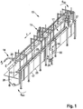
- Fig. 1
- eine schematische Darstellung der erfindungsgemäßen Vorrichtung in perspektivischer Ansicht von schräg oben und vorne,
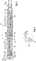
- Fig. 2
- die Vorrichtung gemäß
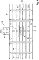
Figur 1 in Draufsicht, - Fig. 3
- eine vergrößerte Darstellung des Ausschnitts III gemäß
Figur 2 , - Fig. 4
- eine vergrößerte Darstellung des Verwirbelungskörpers in Draufsicht,
- Fig. 5
- eine vergrößerte Darstellung des Verwirbelungskörpers in perspektivischer Ansicht,
- Fig. 6
- die Vorrichtung gemäß
Figur 2 im Schnitt VI-VI, - Fig. 7
- die Vorrichtung gemäß
Figur 2 im Schnitt VII-VII, - Fig. 8
- eine perspektivische Detailansicht eines Abschnitts einer Transportstrecke, wobei zur Verdeutlichung der Ansicht eine Außenwand des Brühtanks entfernt ist, und
- Fig. 9
- eine schematische Darstellung des Wirkungsprinzips einer Vortex-Wasserturbine.
- Die in der Zeichnung dargestellte Vorrichtung dient zum Brühen von Kopf über nach unten hängenden Hühnchen, die innerhalb des Brühtanks mit einem sehr hohen Niveau des Brühmediums transportiert werden, nämlich derart, dass sich die Hühnchen vollständig unterhalb der Oberfläche des Brühmediums befinden, so dass die Hühnchen durch das in den Transportstrecken stehende Brühmedium und zusätzlich durch das an den Stirnseiten und oben aus dem Kanal strömende Brühmedium beaufschlagt werden. Selbstverständlich kann das Niveau des Brühmediums auch niedriger sein, derart, dass die Hühnchen gar nicht oder nur teilweise in das Brühmedium eintauchen, beispielsweise bis zum Hals, so dass die Hühnchen ausschließlich oder überwiegend durch das von oben aus dem Kanal strömende Brühmedium beaufschlagt werden. Die Erfindung ist in entsprechender Weise auch für Truthähne, Ente, Gänse und andere Vögel und Wasservögel einsetzbar.
- In der
Figur 1 ist eine Vorrichtung 10 dargestellt, die zum Brühen von geschlachtetem Geflügel G, ausgebildet und eingerichtet ist. Die Vorrichtung 10 umfasst einen länglichen, nach oben offenen Brühtank 11 zur Aufnahme und zum Halten eines Brühmediums mit mindestens einer Transportstrecke 12.1 für das Geflügel G, wobei jede Transportstrecke 12.1 in ihrer Längserstreckung an ein sich mindestens über einen Teil der Länge der Transportstrecke 12.1 erstreckendes Trennelement 13 grenzt. Weiterhin umfasst die Vorrichtung 10 ein oberhalb des Brühtanks 11 angeordnetes Transportmittel 14 zum Transport des an den Füßen aufgehängten Geflügels G entlang der Transportstrecke 12.1 in Transportrichtung T sowie eine Steuer- und Regeleinheit 15 zum Temperieren des Brühmediums. Des Weiteren umfasst die Vorrichtung 10 Mittel 16 zum Erzeugen einer Verwirbelung und/oder Strömung des Brühmediums sowie eine Filtereinrichtung 35 zum Reinigung des Brühmediums. - Diese Vorrichtung 10 zeichnet sich erfindungsgemäß dadurch aus, dass jedes Trennelement 13 zwei beabstandet zueinander angeordnete und sich von der Bodenwand 17 des Brühtanks 11 nach oben erstreckende Trennwände 18,19 zur Bildung eines nach oben und zu den Stirnseiten SK1,SK2 hin offenen Kanals 20 umfasst, und innerhalb des Kanals 20 im Bereich von Durchbrüchen 21, 22 in jeder einer Transportstrecke 12.1 zugewandten Trennwand 18, 19 ein Verwirbelungskörper 23 als Mittel 16 zur Erzeugung der Verwirbelung und/oder Strömung des Brühmediums angeordnet ist, der mittels einer horizontal gerichteten und quer zur Transportrichtung T des Geflügels G verlaufenden Antriebswelle 24 rotierend antreibbar ist. Ein einzelner Verwirbelungskörper 23 kann sich über die gesamte Kanalbreite erstrecken, so dass sich der einzige Verwirbelungskörper 23 in den Bereich beider Durchbrüche 21, 22 erstreckt. Es kann aber auch im Bereich jedes Durchbruches 21, 22 ein separater Verwirbelungskörper 23 angeordnet sein.
- Die im Folgenden beschriebenen Merkmale und Weiterbildungen stellen für sich betrachtet oder in Kombination miteinander bevorzugte Ausführungsformen dar. Es wird ausdrücklich darauf hingewiesen, dass Merkmale, die in den Ansprüchen und/oder der Beschreibung zusammengefasst oder in einer gemeinsamen Ausführungsform beschrieben sind, auch funktional eigenständig die weiter oben beschriebene Vorrichtung 10 weiterbilden können.
- Der Brühtank 11 ist ein wannenartiger Körper, der nach unten durch die Bodenwand 17 und seitlich durch die Seitenwände 25, 26 begrenzt ist. Der Brühtank 11 erstreckt sich in Transportrichtung T in Längsrichtung. Die gegenüber den Seitenwänden 25, 26 deutlich kürzeren Stirnwände 27, 28 begrenzen den Brühtank 11 zur Bildung des Aufnahmevolumens für das Brühmedium, so dass dieses aufgenommen und gehalten, also bevorratet werden kann. Das Brühmedium kann Wasser oder ein anderes Fluid sein, beispielsweise mit mindestens einem Zusatzstoff angereichertes Wasser oder dergleichen. Die Bodenwand 17 kann horizontal und eben oder, wie in der
Figur 1 dargestellt, auch V-förmig ausgebildet sein. Der Brühtank 11 kann einstückig oder modular bzw. segmentartig ausgebildet sein und weist in der dargestellten Variante eine Gesamtlänge von bevorzugt ca. 8m auf. Die Dimensionen des Brühtanks 11 können aber variieren. - Bei der in der Zeichnung dargestellten Vorrichtung 10 sind in dem Brühtank 11 mindestens zwei parallel verlaufende Transportstrecken 12.1, 12.2 ausgebildet, die in ihrer Längserstreckung durch das Trennelement 13 mindestens teilweise voneinander getrennt sind. An einer der Stirnseiten SB1 des Brühtanks 11 erfolgt sowohl die Eingabe als auch die Ausgabe des Geflügels G. Das Transportmittel 14 ist in der bevorzugten Ausführungsform ein als über-Kopf-Förderer ausgebildeter Hängeförderer, an dem das Geflügel G mit den Füßen in Schäkeln 29 hängend entlang der Transportstrecken 12.1, 12.2 gefördert wird. Der Hängeförderer bzw. dessen Förderschiene ist meanderförmig geführt, derart, dass die Förderschiene an der der Eingabe und Ausgabe gegenüberliegenden Stirnseite SB2 um 180° umgelenkt ist, um dem Geflügel G den Wechsel von der einen Transportstrecke 12.1 in die andere Transportstrecke 12.2 zu ermöglichen. Entsprechend ist das Trennelement 13 mindestens auf der der Stirnseite SB2 zugewandten Seite beabstandet zur Stirnwand 27 des Brühtanks 11 ausgebildet. In der zuvor beschriebenen Weise sind auch Vorrichtungen 10 ausgebildet, bei denen in dem Brühtank 11 mehr als zwei parallel verlaufende Transportstrecken 12.1, 12.2,.....12.n ausgebildet sind. In diesem Fall sind zwei benachbarte Transportstrecken 12.1, 12.2,.....12.n jeweils durch ein Trennelement 13 mindestens teilweise voneinander getrennt. Der Hängeförderer bzw. dessen Förderschiene ist entsprechend meanderförmig gelenkt. Für den Fall, dass mehr als zwei Transportstrecken 12.1, 12.2,....12.n vorgesehen sind, ist jedes Trennelement 13 auch auf der Stirnseite SB1 im Bereich der Eingabe und Ausgabe beabstandet zur Stirnwand 28 des Brühtanks 11 ausgebildet.
- Der Verwirbelungskörper 23 ist im dargestellten Ausführungsbeispiel zentral angeordnet. Anders ausgedrückt ist der oder jeder Verwirbelungskörper 23 etwa mittig bezogen auf die Länge der Transportstrecken 12.1, 12.2,....12.n zentral auf einer einzelnen Antriebswelle 24 angeordnet, die mittels eines einzelnen Antriebs 30 rotierend antreibbar ist. Die Antriebswelle 24 ist in den Seitenwänden 25, 26 des Brühtanks 11 und optional zusätzlich in den Trennwänden 18, 19 des Trennelementes 13 gelagert. Der Verwirbelungskörper 23 umfasst mindestens einen Impeller oder einen Propeller oder eine Turbine oder ein anderes Verwirbelungselement. Besonders bevorzugt umfasst der Verwirbelungskörper 23 mindestens eine Vortex-Wasserturbine, die zwischen den beiden Trennwänden 18, 19 im Bereich der Durchbrüche 21, 22 angeordnet ist und bei geringer Umdrehungszahl (z.B. von 300U/min) ein sehr hohes Pumpvolumen aufweist. Beim Einsatz einer Vortex-Wasserturbine kann diese ein Rotorblatt oder zwei Rotorblätter aufweisen. Für den Fall, dass zwei Rotorblätter vorgesehen sind, können diese durch eine Trennwand oder dergleichen voneinander getrennt sein. Wenn die Vortex-Wasserturbine nur ein Rotorblatt aufweist, das dann auch nur einer Trennwand 18, 19 zugewandt ist, wird auch nur Brühmedium aus der Transportstrecke 12.1, 12.2,....12.n gesaugt, zu der das Rotorblatt gerichtet ist. Wenn zwei Rotorblätter die Vortex-Wasserturbine bilden, ist beiden benachbart zum Kanal 20 liegenden Transportstrecken 12.1, 12.2,...12.n ein Rotorblatt zugeordnet, mittels dem das Brühmedium zur Erzeugung des Überdrucks innerhalb des Kanals 20 abgesaugt werden kann. Alternativ kann der oder jeder Verwirbelungskörper 23 auch außermittig und insbesondere an den Stirnseiten SK1, SK2 des Kanals 20 angeordnet sein. Für den Fall, dass der Verwirbelungskörper 23 eine Vortex-Wasserturbine ist, kann diese bevorzugt an der der Eingabe E und Ausgabe A zugewandten Stirnseite SK1 des Kanals 20 in diesem angeordnet sein.
- Im Bereich eines vorzugsweise U-förmigen Kanals 20 kann der Verwirbelungskörper 23 in einer Trennwand 18, 19 oder in beiden Trennwänden 18, 19 im Bereich der Durchbrüche 21, 22 einen Impeller oder einen Propeller aufweisen. Für den Fall, dass mehrere Kanäle 20 parallel und beabstandet nebeneinanderliegen, besteht die Möglichkeit, dass in jedem Kanal 20 eine Vortex-Wasserturbine oder ein oder zwei Impeller oder Propeller angeordnet sind, wobei sämtliche Vortex-Wasserturbinen und/oder Impeller und/oder Propeller einer Vorrichtung 10 auf derselben Antriebswelle 24 angeordnet sind. Optional können auch mehrere Brühtanks 11 als Module nebeneinander angeordnet sein, so dass sich eine Antriebswelle 24 durch mehrere Brühtanks 11 hindurch erstreckt und in diesen gelagert ist, um alle Verwirbelungskörper 23 einer aus zwei oder mehr Brühtanks 11 bestehenden Anordnung zu tragen und anzutreiben.
- Vorzugsweise ist an beiden Stirnseiten SK1, SK2 jedes Kanals 20 im Bereich der Trennwände 18, 19 jeweils mindestens ein Umlenkelement 31, 32 zum Umlenken des an den Stirnseiten SK1, SK2 aus dem Kanal 20 strömenden Brühmediums in Transportrichtung T des Geflügels G angeordnet. In der
Figur 3 ist eine einfache Ausführungsform eines Umlenkelementes 31 dargestellt, das am Ende des U-förmigen Kanals 20 an einer Trennwand 18, 19 angeordnet ist und den durch den Verwirbelungskörper 23 erzeugten Strom des Brühmediums derart umlenkt, dass das Brühmedium in den Transportstrecken 12.1, 12.2,....12.n der Transportrichtung T des Geflügels G in horizontaler Richtung folgt. Die Umlenkung kann auch durch andere, z.B. zu den Trennwänden 18,19 separate Umlenkelemente oder dergleichen erfolgen. Des Weiteren besteht die Möglichkeit, auch nur an einer der beiden Stirnseiten SK1, SK2 des Kanals 20 ein Umlenkelement 31 vorzusehen. - Wie in der Zeichnung dargestellt, sind im Bereich des nach oben offenen Kanals 20 Prallelemente 33 zum Umlenken des nach oben aus dem offenen Kanal 20 strömenden Brühmediums nach unten in Richtung des Geflügels G angeordnet. Die Prallelemente 33 können sich über einen Teil der Länge des Kanals 20 oder über die gesamte Länge erstrecken. Jedes Prallelement 33 kann zum Umlenken des Brühmediums zu der einen Seite (z.B. Transportstrecke 12.1) oder zu der anderen Seite (z.B. Transportstrecke 12.2) oder zu beiden Seiten (z.B. Transportstrecken 12.1 und 12.2) ausgebildet und eingerichtet sein. Die Prallelemente 33 sind vorzugsweise einfache Leitkörper oder dergleichen mit einer die Strömung unterstützenden, abgerundeten Innenfläche, die an einer der Trennwände 18, 19 angeordnet sind.
- Jeweils zwei Trennwände 18, 19 bilden den Kanal 20, der bevorzugt U-förmig ausgebildet ist. Die Trennwände 18, 19 erstrecken sich von der Bodenwand 17 des Brühtanks 11 nach oben, und zwar bevorzugt bis unterhalb der Oberkante der Seitenwände 25, 26 des Brühtanks 11, so dass die Oberkanten der Trennwände 18, 19 bei maximalem Füllstand des Brühtanks 11 mit Brühmedium unterhalb der Oberfläche O des Brühmediums liegen (siehe z.B.
Figuren 6 und7 ). Optional und bevorzugt sind die Trennwände 18, 19 parallel beabstandet zueinander angeordnet. Sie können fest mit dem Brühtank 11 verbunden sein. Bevorzugt sind die Trennwände 18, 19 insbesondere zu Wartungs- und Reinigungszwecken jedoch schwenkbar ausgebildet. Dazu ist jede Trennwand 18, 19 im Bereich der Bodenwand 17 des Brühtanks 11 mit einem Scharnier 36 oder dergleichen zum Schwenken der Trennwände 18, 19 aus einer parallelen Betriebsstellung in eine V-förmige Wartungs- und/oder Reinigungsstellung und zurück versehen. Mit anderen Worten sind die Trennwände 18, 19 mittels eines Scharniers 36 oder dergleichen an der Bodenwand 17 befestigt. Mittels einer nicht dargestellten Arretiereinrichtung sind die Trennwände 18, 19 mindestens in ihrer Betriebsstellung fixierbar. Es besteht auch die Möglichkeit, dass nur eine der Trennwände 18,19 schwenkbar ausgebildet ist. Des Weiteren können auch nur Teile der Trennwände 18, 19 in ihrer horizontalen und/oder vertikalen Erstreckung schwenkbar oder klappbar ausgebildet und eingerichtet sein. - Wie bereits beschrieben, ist der Verwirbelungskörper 23 innerhalb des Kanals 20 angeordnet. Jeder Verwirbelungskörper 23, insbesondere für den Fall, dass der Verwirbelungskörper 23 ein einfacher Impeller oder Propeller ist, ist im Bereich der Durchbrüche 21, 22 gegenüber den Transportstrecken 12.1, 12.2...12.n durch ein für das Brühmedium durchlässiges Schutzelement 34 abgeschirmt. In der
Figur 8 ist ein einfaches Schutzgitter dargestellt, das verhindert, dass das Geflügel G in direkten Kontakt mit dem Verwirbelungskörper 23 kommen kann. Vorzugsweise ist das Schutzelement 34 ausgebildet und eingerichtet, um auch die Antriebswelle 24, die sich quer durch die Transportstrecken 12.1, 12.2,....12.n und den oder jeden Kanal 20 erstreckt, gegenüber dem Geflügel G abzuschirmen. - Die Steuer- und Regeleinheit 15 zum Temperieren des Brühmediums kann an beliebiger Position innerhalb der Vorrichtung 10 angerordnet sein. Beispielsweise ist eine Anordnung der oder jeder Wärmequelle der Steuer- und Regeleinheit 15 innerhalb des Brühtanks 11 im Bereich der Transportstrecken 12.1, 12.2,...12.n möglich. Besonders bevorzugt ist die oder jede Wärmequelle der Steuer- und Regeleinheit 15 jedoch innerhalb des Kanals 20 angeordnet. Ebenso ist ein Sensor oder dergleichen der Steuer- und Regeleinheit 15 vorzugsweise innerhalb des Kanals 20 angeordnet.
- Die Filtereinrichtung 35 zum Filtern des Brühmediums und/oder zum Kontrollieren und Regeln des Niveaus des Brühmediums innerhalb des Brühtanks 11, und damit innerhalb der Transportstrecken 12.1, 12.2,...12.n und der Kanäle 20 kann ebenfalls an beliebiger Position innerhalb der Vorrichtung 10 angeordnet sein. In der Ausführungsform gemäß
Figur 2 ist die Filtereinrichtung 35 an der Stirnseite SB2 angeordnet. Die Filtereinrichtung 35 kann aber auch an der Stirnseite SB1 angeordnet sein, und zwar im Bereich der Stirnseite SK1 des Kanals 20, also am Ende des Trennelementes 13 zwischen den Förderschienen des Transportmittels 14. - Im Folgenden wird das erfindungsgemäße Verfahren zum Brühen von geschlachtetem Geflügel, das zur Vorbereitung des Entfiederns des Geflügels dient, anhand der Zeichnung näher erläutert.
Das an den Füßen hängende Geflügel G wird - vorzugsweise mit dem Rücken zur Trennwand 18, 19 weisend - durch einen mit Brühmedium mindestens teilweise gefüllten Brühtank 11 mittels eines Transportmittels 14 entlang einer Transportstrecke 12.1, 12.2,....12.n in Transportrichtung T transportiert. Damit das Brühmedium den gewünschten Effekt des Anlösens der Federn erzielt, wird das Brühmedium mittels einer Steuer- und Regeleinheit 15 auf die gewünschte Brühtemperatur temperiert und diese Brühtemperatur wird während des Betriebs auch gesteuert und geregelt. Während des Betriebs oder in Betriebsunterbrechungen wird das Brühmedium durch eine Filtereinrichtung 35 gereinigt. Um das Brühmedium möglichst effektiv mit dem Geflügel in Kontakt zu bringen, wird das Brühmedium mittels eines Mittels 16 zum Erzeugen einer Verwirbelung und/oder Strömung verwirbelt. - Erfindungsgemäß zeichnet sich das Verfahren dadurch aus, dass das Brühmedium in einem von der oder jeder Transportstrecke 12.1, 12.2,....12.n mindestens teilweise abgeschirmten Kanal 20 mittels eines Verwirbelungskörpers 23, der um eine horizontal gerichtete und quer zur Transportrichtung T verlaufende Antriebswelle 24 rotierend angetrieben wird, verwirbelt und dann wieder der oder jeder Transportstrecke 12.1, 12.2,....12.n zugeführt wird.
- Dazu wird das Brühmedium vorzugsweise aus der oder jeder Transportstrecke 12.1, 12.2,...12.n mittels des Verwirbelungskörpers 23 in den Kanal 20 gesaugt, wodurch in dem Kanal 20 ein Überdruck erzeugt wird, der dafür sorgt, dass das Brühmedium an den Stirnseiten SK1, SK2 und/oder an der Oberseite des Kanals 20 austritt und wieder den Transportstrecken 12.1, 12.2,....12.n zugeführt wird. Das aus den Stirnseiten SK1, SK2 des Kanals 20 austretende Brühmedium wird vorzugsweise durch Umlenkelemente 31, 32 derart umgelenkt, dass das austretende Brühmedium in Transportrichtung T des Geflügels G strömt. Mit anderen Worten wir das Geflügel G stets mit der Strömungsrichtung des Brühmediums transportiert. Das nach oben aus dem Kanal 20 austretende Brühmedium kann durch Prallelemente 33 derart umgelenkt werden, dass das hängende Geflügel G durch das austretende Brühmedium gegen den Federwuchs von oben nach unten mit diesem beaufschlagt wird.
- In einer ersten Ausführungsform wird das Geflügel G entlang der Transportstrecken 12.1, 12.2,....12.n durch einen nur gering mit Brühmedium befüllten Brühtank 11 transportiert, so dass das Geflügel G gar nicht oder nur geringfügig in das Brühmedium eintaucht und vollständig oder überwiegend durch das oben aus dem Kanal 20 strömende Brühmedium mit diesem beaufschlagt wird. Bei dieser Ausführungsform hängt das Geflügel G in den Transportstrecken, berührt das Brühmedium aber gar nicht bzw. taucht nur leicht, beispielsweise nur bis zum Hals, in das Brühmedium ein, um die beim Transport durch das Brühmedium entstehende Rückhaltekraft zu vermeiden bzw. sehr gering zu halten. Das Brühmedium weist lediglich ein solches Niveau in dem Brühtank 11 auf, dass es mittels des Verwirbelungskörpers 23, insbesondere mittels der Vortex-Wasserturbine, in den Kanal 20 gesaugt und aus diesem über die Prallelemente 33 von oben nach unten über das Geflügel G zurückgeführt wird. In diesem Fall erfolgt das Brühen im Wesentlichen durch das oben aus dem Kanal 20 strömende Brühmedium.
- Alternativ wird das Geflügel G entlang der Transportstrecken 12.1, 12.2,....12.n durch einen voll mit Brühmedium befüllten Brühtank 11 transportiert, so dass das Geflügel G vollständig in das Brühmedium eintaucht und durch das in den Transportstrecken 12.1, 12.2,...12.n stehende und durch das oben und/oder an den Stirnseiten aus dem Kanal 20 strömende Brühmedium mit diesem beaufschlagt (siehe z.B.
Figuren 6 und7 ). Das aus dem Kanal 20 strömende Brühmedium bewirkt eine Verwirbelung des in den Transportstrecken 12.1, 12.2,...12.n stehenden Brühmediums, so dass eine besonders effektive Beaufschlagung des Geflügels G mit Brühmedium sichergestellt ist. - Vorzugsweise wird das Brühmedium innerhalb des Kanals 20 durch die Steuer- und Regeleinheit 15 temperiert, wobei sich das in dem Kanal 20 temperierte Brühmedium beim Ausströmen aus dem Kanal 20 mit dem in den Transportstrecken 12.1, 12.2,...12.n befindlichen Brühmedium vermischt und diese Brühmediummischung dann auf das Geflügel G trifft. In der
Figur 9 ist schematisch angedeutet, welchen Effekt der Verwirbelungskörper 23 und insbesondere die Vortex-Wasserturbine aufweist, nämlich eine Verwirbelung des Brühmediums derart, dass das Brühmedium innerhalb des Kanals 20 unter Erzeugung eines Überdrucks gleichmäßig in alle Richtungen gelenkt wird. - Besonders eignet sich die erfindungsgemäße Vorrichtung 10 zur Durchführung des Verfahrens.
Claims (20)
- Vorrichtung (10), ausgebildet und eingerichtet zum Brühen von geschlachtetem Geflügel G, umfassend einen länglichen, nach oben offenen Brühtank (11) zur Aufnahme und zum Halten eines Brühmediums mit mindestens einer Transportstrecke (12.1, 12.2,....12.n) für das Geflügel G, wobei jede Transportstrecke (12.1, 12.2,....12.n) in ihrer Längserstreckung an ein sich mindestens über einen Teil der Länge der Transportstrecke (12.1, 12.2....12.n) erstreckendes Trennelement (13) grenzt, ein oberhalb des Brühtanks (11) angeordnetes Transportmittel (14) zum Transport des an den Füßen aufgehängten Geflügels G entlang der Transportstrecke (12.1, 12.2,....12.n) in Transportrichtung T, eine Steuer- und Regeleinheit (15) zum Temperieren des Brühmediums, Mittel (16) zum Erzeugen einer Verwirbelung und/oder Strömung des Brühmediums sowie eine Filtereinrichtung (35) zum Reinigen des Brühmediums, wobei jedes Trennelement (13) zwei beabstandet zueinander angeordnete und sich von der Bodenwand (17) des Brühtanks (11) nach oben erstreckende Trennwände (18, 19) zur Bildung eines nach oben und zu den Stirnseiten hin offenen Kanals (20) umfasst, und innerhalb des Kanals(20) im Bereich von Durchbrüchen (21, 22) in jeder einer Transportstrecke (12.1, 12.2,....12.n) zugewandten Trennwand (18, 19) ein Verwirbelungskörper (23) als Mittel (16) zur Erzeugung der Verwirbelung und/oder Strömung des Brühmediums angeordnet ist, der mittels einer horizontal gerichteten und quer zur Transportrichtung T des Geflügels G verlaufenden Antriebswelle (24) rotierend antreibbar ist.
- Vorrichtung (10) nach Anspruch 1, dadurch gekennzeichnet, dass in dem Brühtank (11) mindestens zwei parallel verlaufende Transportstrecken (12.1, 12.2,....12.n) ausgebildet sind, die in ihrer Längserstreckung durch das Trennelement (13) mindestens teilweise voneinander getrennt sind.
- Vorrichtung (10) nach Anspruch 1 oder 2, dadurch gekennzeichnet, dass in dem Brühtank (11) mehr als zwei parallel verlaufende Transportstrecken (12.1, 12.2,....12.n) ausgebildet sind, wobei zwei benachbarte Transportstrecken (12.1, 12.2,....12.n) jeweils durch ein Trennelement (13) mindestens teilweise voneinander getrennt sind.
- Vorrichtung (10) nach einem oder mehreren der Ansprüche 1 bis 3, dadurch gekennzeichnet, dass der Verwirbelungskörper (23) mindestens einen Impeller, Propeller oder dergleichen umfasst.
- Vorrichtung (10) nach einem oder mehreren der Ansprüche 1 bis 4, dadurch gekennzeichnet, dass der Verwirbelungskörper (23) mindestens zwei Impeller, Propeller oder dergleichen umfasst, die auf derselben Antriebswelle (24) angeordnet sind.
- Vorrichtung (10) nach einem oder mehreren der Ansprüche 1 bis 5, dadurch gekennzeichnet, dass an beiden Stirnseiten jedes Kanals (20) im Bereich der Trennwände (18, 19) jeweils mindestens ein Umlenkelement (31, 32) zum Umlenken des an den Stirnseiten aus dem Kanal (20) strömenden Brühmediums in Transportrichtung T des Geflügels angeordnet ist.
- Vorrichtung (10) nach einem oder mehreren der Ansprüche 1 bis 6, dadurch gekennzeichnet, dass im Bereich des nach oben offenen Kanals (20) Prallelemente (33) zum Umlenken des nach oben aus dem Kanal (20) strömenden Brühmediums nach unten in Richtung des Geflügels angeordnet sind.
- Vorrichtung (10) nach Anspruch 7, dadurch gekennzeichnet, dass sich die Prallelemente (33) im Wesentlichen über die gesamte Länge des Kanals (20) erstrecken und wahlweise zum Umlenken des Brühmediums aus dem Kanal (20) zu der einen und/oder zu der anderen Transportstrecke (12.1, 12.2,....12.n) ausgebildet und eingerichtet sind.
- Vorrichtung (10) nach einem oder mehreren der Ansprüche 1 bis 8, dadurch gekennzeichnet, dass die beiden einen Kanal (20) bildenden Trennwände (18, 19) zu Wartungs- und/oder Reinigungszwecken schwenkbar ausgebildet sind.
- Vorrichtung (10) nach Anspruch 9, dadurch gekennzeichnet, dass jede Trennwand (18, 19) im Bereich der Bodenwand (17) des Brühtanks (11) mit einem Scharnier (36) oder dergleichen zum Schwenken der Trennwände (18, 19) aus einer parallelen Betriebsstellung in eine V-förmige Wartungs- und/oder Reinigungsstellung und zurück versehen ist.
- Vorrichtung (10) nach einem oder mehreren der Ansprüche 1 bis 10, dadurch gekennzeichnet, dass jeder Verwirbelungskörper (23) im Bereich der Durchbrüche (21, 22) gegenüber den Transportstrecken (12.1, 12.2,....12.n) durch ein für das Brühmedium durchlässiges Schutzelement (34) abgeschirmt ist.
- Vorrichtung (10) nach einem oder mehreren der Ansprüche 1 bis 11, dadurch gekennzeichnet, dass mindestens eine Wärmequelle der Steuer- und Regeleinheit (15) zum Temperieren des Brühmediums innerhalb des Kanals (20) angeordnet ist.
- Verfahren zum Brühen von geschlachtetem Geflügel, mit den Schritten:- Transportieren des Geflügels G an den Füßen hängend durch einen mit Brühmedium mindestens teilweise gefüllten Brühtank (11) mittels eines Transportmittels (14) entlang einer Transportstrecke (12.1, 12.2,....12.n) in Transportrichtung T,- Temperieren des Brühmediums mittels einer Steuer- und Regeleinheit (15),- Reinigen des Brühmediums mittels einer Filtereinrichtung (35), und- Verwirbeln des Brühmediums mittels eines Mittels (16) zum Erzeugen einer Verwirbelung und/oder Strömung,wobei das Brühmedium in einem von der oder jeder Transportstrecke (12.1, 12.2,....12.n) mindestens teilweise abgeschirmten Kanal (20) mittels eines Verwirbelungskörpers (23), der um eine horizontal gerichtete und quer zur Transportrichtung T verlaufende Antriebswelle (24) rotierend angetrieben wird, verwirbelt und dann wieder der oder jeder Transportstrecke (12.1, 12.2,....12.n) zugeführt wird.
- Verfahren nach Anspruch 13, dadurch gekennzeichnet, dass das Brühmedium aus der oder jeder Transportstrecke mittels des Verwirbelungskörpers (23) in den Kanal (20) gesaugt und dadurch in dem Kanal (20) ein Überdruck erzeugt wird, der dafür sorgt, dass das Brühmedium an den Stirnseiten und/oder an der Oberseite des Kanals(20) austritt und wieder den Transportstrecken (12.1, 12.2,....12.n) zugeführt wird.
- Verfahren nach Anspruch 14, dadurch gekennzeichnet, dass das aus den Stirnseiten des Kanals (20) austretende Brühmedium durch Umlenkelemente (31, 32) derart umgelenkt wird, dass das austretende Brühmedium in Transportrichtung T des Geflügels G strömt.
- Verfahren nach einem oder mehreren der Ansprüche 13 bis 15, dadurch gekennzeichnet, dass das nach oben aus dem Kanal (20) austretende Brühmedium durch Prallelemente (33) derart umgelenkt wird, dass das hängende Geflügel G durch das austretende Brühmedium von oben nach unten mit diesem beaufschlagt wird.
- Verfahren nach einem oder mehreren der Ansprüche 13 bis 16, dadurch gekennzeichnet, dass das Geflügel G entlang der Transportstrecken (12.1, 12.2,....12.n) durch einen nur gering mit Brühmedium befüllten Brühtank (11) transportiert wird, so dass das Geflügel G gar nicht oder nur geringfügig in das Brühmedium eintaucht und vollständig oder überwiegend durch das oben aus dem Kanal (20) strömende Brühmedium mit diesem beaufschlagt wird.
- Verfahren nach einem oder mehreren der Ansprüche 13 bis 16, dadurch gekennzeichnet, dass das Geflügel G entlang der Transportstrecken (12.1, 12.2,....12.n) durch einen voll mit Brühmedium befüllten Brühtank (11) transportiert wird, so dass das Geflügel G vollständig in das Brühmedium eintaucht und durch das in den Transportstrecken (12.1, 12.2,...12.n) stehende und durch das oben und/oder an den Stirnseiten aus dem Kanal (20) strömende Brühmedium mit diesem beaufschlagt.
- Verfahren nach einem oder mehreren der Ansprüche 13 bis 18, dadurch gekennzeichnet, dass das Brühmedium innerhalb des Kanals (20) durch die Steuer- und Regeleinheit (15) temperiert wird, wobei sich das in dem Kanal (20) temperierte Brühmedium beim Ausströmen aus dem Kanal (20) mit dem in den Transportstrecken (12.1, 12.2,...12.n) befindlichen Brühmedium vermischt und diese Brühmediummischung dann auf das Geflügel G trifft.
- Verfahren nach einem oder mehreren der Ansprüche 13 bis 19, dadurch gekennzeichnet, dass es mit einer Vorrichtung nach einem der Ansprüche 1 bis 12 ausgeführt wird.
Priority Applications (1)
| Application Number | Priority Date | Filing Date | Title |
|---|---|---|---|
| PL16712301T PL3273785T3 (pl) | 2015-03-26 | 2016-03-21 | Sposób i urządzenie do parzenia ubitego drobiu |
Applications Claiming Priority (2)
| Application Number | Priority Date | Filing Date | Title |
|---|---|---|---|
| DE102015104652.0A DE102015104652B3 (de) | 2015-03-26 | 2015-03-26 | Vorrichtung und Verfahren zum Brühen von geschlachtetem Geflügel |
| PCT/EP2016/056113 WO2016150904A1 (de) | 2015-03-26 | 2016-03-21 | Vorrichtung und verfahren zum brühen von geschlachtetem geflügel |
Publications (2)
| Publication Number | Publication Date |
|---|---|
| EP3273785A1 EP3273785A1 (de) | 2018-01-31 |
| EP3273785B1 true EP3273785B1 (de) | 2018-12-19 |
Family
ID=55274158
Family Applications (1)
| Application Number | Title | Priority Date | Filing Date |
|---|---|---|---|
| EP16712301.7A Active EP3273785B1 (de) | 2015-03-26 | 2016-03-21 | Vorrichtung und verfahren zum brühen von geschlachtetem geflügel |
Country Status (17)
| Country | Link |
|---|---|
| US (1) | US10064415B2 (de) |
| EP (1) | EP3273785B1 (de) |
| JP (1) | JP6343724B2 (de) |
| KR (1) | KR101866154B1 (de) |
| CN (1) | CN107427015B (de) |
| BR (1) | BR112017020257B1 (de) |
| CA (1) | CA2977514C (de) |
| DE (1) | DE102015104652B3 (de) |
| DK (1) | DK3273785T3 (de) |
| ES (1) | ES2715128T3 (de) |
| MY (1) | MY168989A (de) |
| PH (1) | PH12017501768A1 (de) |
| PL (1) | PL3273785T3 (de) |
| PT (1) | PT3273785T (de) |
| RU (1) | RU2648052C1 (de) |
| TR (1) | TR201902706T4 (de) |
| WO (1) | WO2016150904A1 (de) |
Families Citing this family (5)
| Publication number | Priority date | Publication date | Assignee | Title |
|---|---|---|---|---|
| CN110353023B (zh) * | 2018-04-10 | 2023-12-29 | 东莞市金鸿昌机械设备有限公司 | 一种家禽脱毛方法以及家禽脱毛设备 |
| CN110122532A (zh) * | 2019-06-12 | 2019-08-16 | 山东省农业科学院畜牧兽医研究所 | 一种生猪屠宰用立式浸烫脱毛一体化装置 |
| CN110353024A (zh) * | 2019-08-16 | 2019-10-22 | 清远清农电商有限公司 | 一种基于空气能的禽类液烫系统 |
| CN114929023B (zh) * | 2020-03-06 | 2023-04-28 | 丹麦巴德尔食品系统公司 | 用于浸烫已屠宰的家禽的装置及方法 |
| WO2023023539A1 (en) * | 2021-08-17 | 2023-02-23 | Safe Foods Corporation | Dual waterfall cabinet for food processing applications |
Family Cites Families (24)
| Publication number | Priority date | Publication date | Assignee | Title |
|---|---|---|---|---|
| US3703744A (en) * | 1971-01-13 | 1972-11-28 | Food Equipment Inc | Fowl singeing system |
| KR840000937Y1 (ko) | 1982-10-05 | 1984-06-14 | 범진기건주식회사 | 닭의 데침기 |
| JPS60191192U (ja) * | 1984-05-30 | 1985-12-18 | 株式会社石井製作所 | ブロイラ−用湯漬け装置 |
| US4868950A (en) * | 1989-01-03 | 1989-09-26 | Centennial Machine Company, Inc. | Fowl scalding apparatus and method |
| US4852215A (en) * | 1989-02-27 | 1989-08-01 | Covell Iii Edward H | Poultry scalding system and process |
| US4996741A (en) | 1990-07-27 | 1991-03-05 | Covell Iii Edward H | Poultry washing and scalding system and process |
| US5326308A (en) * | 1993-04-23 | 1994-07-05 | Norrie Lyle W | Vertical scalding apparatus |
| US5879732A (en) * | 1996-09-10 | 1999-03-09 | Boc Group, Inc. | Food processing method |
| US5939115A (en) * | 1997-02-03 | 1999-08-17 | Zheko V. Kounev | Method and apparatus for decontaminating poultry carcasses |
| NL1009188C2 (nl) | 1998-05-18 | 1999-11-19 | J M Poultry Technology B V | Inrichting, broeibak en werkwijze voor het broeien van geslacht pluimvee. |
| US7217437B2 (en) | 2000-05-09 | 2007-05-15 | Topkip B.V. | Method and installation for cooling slaughtered poultry |
| EP1280426B2 (de) | 2000-05-09 | 2010-08-25 | Topkip B.V. | Verfahren zum kühlen von schlachtgeflügel |
| AU2003226950A1 (en) * | 2002-04-19 | 2003-11-03 | Linco Food Systems A/S | A method and an apparatus for scalding slaughtered poultry |
| US7288274B2 (en) * | 2004-01-08 | 2007-10-30 | Ecolab Inc. | Method for cleaning poultry |
| ES2339785T3 (es) * | 2004-09-03 | 2010-05-25 | Linco Food Systems A/S | Metodo y sistema para escaldar aves de corral muertas. |
| NL1030458C2 (nl) | 2005-11-18 | 2007-05-21 | Meyn Food Proc Technology Bv | Broei-inrichting. |
| NL2000158C2 (nl) | 2006-07-24 | 2008-01-25 | Stork Pmt | Inrichting en werkwijze voor het broeien van pluimvee. |
| WO2008073819A1 (en) * | 2006-12-08 | 2008-06-19 | Johnsondiversey, Inc. | Cleaning apparatus and method |
| DE102007038815A1 (de) * | 2007-08-16 | 2009-02-19 | Richard Wieck | Hygienisches Entfeuchten von schlachtwarmen Tierkörpern |
| NL2002250C2 (nl) * | 2008-11-25 | 2010-05-26 | Stork Pmt | Inrichting en werkwijze voor het met uiteenlopende intensiteiten broeien van verschillende onderdelen van een pluimveekarkas. |
| US8012002B2 (en) * | 2009-05-21 | 2011-09-06 | Cargill, Incorporated | Animal cleaning system |
| KR20120107149A (ko) | 2011-03-17 | 2012-09-28 | 주식회사 매산씨앤에프 | 냉장용 육계의 탕적장치 |
| KR101435907B1 (ko) | 2012-09-27 | 2014-09-01 | 주식회사 지티 | 탕적기 |
| CN203040553U (zh) * | 2012-11-15 | 2013-07-10 | 南京卓润环保科技有限公司 | 连续悬挂式高效恒温水喷淋烫毛系统 |
-
2015
- 2015-03-26 DE DE102015104652.0A patent/DE102015104652B3/de active Active
-
2016
- 2016-03-21 PT PT16712301T patent/PT3273785T/pt unknown
- 2016-03-21 RU RU2017134231A patent/RU2648052C1/ru active
- 2016-03-21 CN CN201680017030.0A patent/CN107427015B/zh active Active
- 2016-03-21 ES ES16712301T patent/ES2715128T3/es active Active
- 2016-03-21 US US15/555,067 patent/US10064415B2/en active Active
- 2016-03-21 TR TR2019/02706T patent/TR201902706T4/tr unknown
- 2016-03-21 MY MYPI2017001387A patent/MY168989A/en unknown
- 2016-03-21 DK DK16712301.7T patent/DK3273785T3/en active
- 2016-03-21 PL PL16712301T patent/PL3273785T3/pl unknown
- 2016-03-21 BR BR112017020257-3A patent/BR112017020257B1/pt active IP Right Grant
- 2016-03-21 KR KR1020177028057A patent/KR101866154B1/ko active Active
- 2016-03-21 WO PCT/EP2016/056113 patent/WO2016150904A1/de not_active Ceased
- 2016-03-21 CA CA2977514A patent/CA2977514C/en active Active
- 2016-03-21 EP EP16712301.7A patent/EP3273785B1/de active Active
- 2016-03-21 JP JP2017550478A patent/JP6343724B2/ja active Active
-
2017
- 2017-09-26 PH PH12017501768A patent/PH12017501768A1/en unknown
Non-Patent Citations (1)
| Title |
|---|
| None * |
Also Published As
| Publication number | Publication date |
|---|---|
| MY168989A (en) | 2019-01-29 |
| RU2648052C1 (ru) | 2018-03-22 |
| DK3273785T3 (en) | 2019-04-08 |
| US10064415B2 (en) | 2018-09-04 |
| KR20170118232A (ko) | 2017-10-24 |
| PL3273785T3 (pl) | 2019-05-31 |
| JP6343724B2 (ja) | 2018-06-13 |
| CN107427015A (zh) | 2017-12-01 |
| ES2715128T3 (es) | 2019-05-31 |
| CA2977514C (en) | 2018-08-28 |
| CN107427015B (zh) | 2018-12-18 |
| PH12017501768B1 (en) | 2018-03-19 |
| WO2016150904A1 (de) | 2016-09-29 |
| BR112017020257B1 (pt) | 2021-06-01 |
| PH12017501768A1 (en) | 2018-03-19 |
| TR201902706T4 (tr) | 2019-03-21 |
| US20180035683A1 (en) | 2018-02-08 |
| PT3273785T (pt) | 2019-03-20 |
| DE102015104652B3 (de) | 2016-02-25 |
| JP2018509918A (ja) | 2018-04-12 |
| EP3273785A1 (de) | 2018-01-31 |
| KR101866154B1 (ko) | 2018-06-08 |
| CA2977514A1 (en) | 2016-09-29 |
Similar Documents
| Publication | Publication Date | Title |
|---|---|---|
| DE102015104652B3 (de) | Vorrichtung und Verfahren zum Brühen von geschlachtetem Geflügel | |
| EP2059352B1 (de) | Verfahren zur behandlung von flaschen oder dergleichen behälter in einer reinigungsmaschine sowie reinigungsmaschine | |
| DE602004000708T2 (de) | Tunnelspritzgerät für Reihen von Obstgärten, Weingärten oder andere Pflanzen | |
| EP4051007B1 (de) | Vorrichtung und verfahren zum brühen von geschlachtetem geflügel | |
| DE102013105402A1 (de) | Milchaufschäumvorrichtung, Kaffeemaschine, System sowie Reinigungsverfahren | |
| DE3908336A1 (de) | Antrieb fuer luftstroemungseinrichtung einer kaefigbatterie fuer die gefluegelhaltung | |
| WO2012126556A1 (de) | Vorrichtung zum abblasen von flaschenböden | |
| DE60223286T2 (de) | Schlachttierkörperbearbeitungsvorrichtung | |
| EP1952900A1 (de) | Vorrichtung zum Reinigen von Behältnissen | |
| DE3119238C2 (de) | ||
| DE1140682B (de) | Fluessigkeitsverteiler fuer Geschirr-Spueleinrichtungen | |
| DE102008049296A1 (de) | Vorrichtung zum Abblasen oder Trocknen von Kästen oder dergleichen Behältern | |
| DE202010017351U1 (de) | Vorrichtung zur Behandlung von Nahrungsmitteln | |
| DE202009005748U1 (de) | Tunnelfinisher | |
| EP1039053A1 (de) | Vorrichtung zur Reinhaltung eines Flüssigkeitsbehälters | |
| DE19644499C2 (de) | Trocknungseinrichtung sowie Verfahren zum Trocknen von Geschirrteilen und/oder Tabletts in einer Durchlaufgeschirrspülvorrichtung | |
| DE474482C (de) | Vorrichtung zum Entfernen von Ablagerungen an den Laufradschaufeln von Wasserturbinen | |
| DE2115640A1 (de) | Trocknungsanlage zum trocknen von einseitig offenen behaeltern, z.b. dosen | |
| DE102019130611B3 (de) | Reinigungsvorrichtung, Behälter und Verfahren zur Reinigung und/oder Spülung | |
| EP0117548B1 (de) | Vorrichtung zum kontinuierlichen Brühen von Schlachttieren | |
| DE1000254B (de) | Anlage zur Betaeubung von Schlachtschweinen | |
| AT93664B (de) | Maschine zum Besetzen von Bürstenhölzern mit Borsten. | |
| WO2023089004A1 (de) | Luftklingenvorrichtung | |
| DE2516277C2 (de) | Viehfutternäpfe | |
| DE2740459C3 (de) | Vorrichtung zum Steuern von Fischen in gleiche Höhenlage |
Legal Events
| Date | Code | Title | Description |
|---|---|---|---|
| STAA | Information on the status of an ep patent application or granted ep patent |
Free format text: STATUS: THE INTERNATIONAL PUBLICATION HAS BEEN MADE |
|
| PUAI | Public reference made under article 153(3) epc to a published international application that has entered the european phase |
Free format text: ORIGINAL CODE: 0009012 |
|
| STAA | Information on the status of an ep patent application or granted ep patent |
Free format text: STATUS: REQUEST FOR EXAMINATION WAS MADE |
|
| 17P | Request for examination filed |
Effective date: 20171025 |
|
| AK | Designated contracting states |
Kind code of ref document: A1 Designated state(s): AL AT BE BG CH CY CZ DE DK EE ES FI FR GB GR HR HU IE IS IT LI LT LU LV MC MK MT NL NO PL PT RO RS SE SI SK SM TR |
|
| AX | Request for extension of the european patent |
Extension state: BA ME |
|
| DAV | Request for validation of the european patent (deleted) | ||
| DAX | Request for extension of the european patent (deleted) | ||
| GRAP | Despatch of communication of intention to grant a patent |
Free format text: ORIGINAL CODE: EPIDOSNIGR1 |
|
| STAA | Information on the status of an ep patent application or granted ep patent |
Free format text: STATUS: GRANT OF PATENT IS INTENDED |
|
| RIC1 | Information provided on ipc code assigned before grant |
Ipc: A22C 21/04 20060101AFI20180612BHEP Ipc: A22B 5/08 20060101ALI20180612BHEP |
|
| INTG | Intention to grant announced |
Effective date: 20180709 |
|
| GRAS | Grant fee paid |
Free format text: ORIGINAL CODE: EPIDOSNIGR3 |
|
| GRAA | (expected) grant |
Free format text: ORIGINAL CODE: 0009210 |
|
| STAA | Information on the status of an ep patent application or granted ep patent |
Free format text: STATUS: THE PATENT HAS BEEN GRANTED |
|
| AK | Designated contracting states |
Kind code of ref document: B1 Designated state(s): AL AT BE BG CH CY CZ DE DK EE ES FI FR GB GR HR HU IE IS IT LI LT LU LV MC MK MT NL NO PL PT RO RS SE SI SK SM TR |
|
| REG | Reference to a national code |
Ref country code: GB Ref legal event code: FG4D Free format text: NOT ENGLISH |
|
| REG | Reference to a national code |
Ref country code: CH Ref legal event code: EP |
|
| REG | Reference to a national code |
Ref country code: IE Ref legal event code: FG4D Free format text: LANGUAGE OF EP DOCUMENT: GERMAN |
|
| REG | Reference to a national code |
Ref country code: DE Ref legal event code: R096 Ref document number: 502016002918 Country of ref document: DE |
|
| REG | Reference to a national code |
Ref country code: AT Ref legal event code: REF Ref document number: 1077717 Country of ref document: AT Kind code of ref document: T Effective date: 20190115 |
|
| REG | Reference to a national code |
Ref country code: PT Ref legal event code: SC4A Ref document number: 3273785 Country of ref document: PT Date of ref document: 20190320 Kind code of ref document: T Free format text: AVAILABILITY OF NATIONAL TRANSLATION Effective date: 20190307 |
|
| REG | Reference to a national code |
Ref country code: SE Ref legal event code: TRGR |
|
| REG | Reference to a national code |
Ref country code: DK Ref legal event code: T3 Effective date: 20190401 |
|
| REG | Reference to a national code |
Ref country code: NL Ref legal event code: FP |
|
| PG25 | Lapsed in a contracting state [announced via postgrant information from national office to epo] |
Ref country code: HR Free format text: LAPSE BECAUSE OF FAILURE TO SUBMIT A TRANSLATION OF THE DESCRIPTION OR TO PAY THE FEE WITHIN THE PRESCRIBED TIME-LIMIT Effective date: 20181219 Ref country code: LV Free format text: LAPSE BECAUSE OF FAILURE TO SUBMIT A TRANSLATION OF THE DESCRIPTION OR TO PAY THE FEE WITHIN THE PRESCRIBED TIME-LIMIT Effective date: 20181219 Ref country code: NO Free format text: LAPSE BECAUSE OF FAILURE TO SUBMIT A TRANSLATION OF THE DESCRIPTION OR TO PAY THE FEE WITHIN THE PRESCRIBED TIME-LIMIT Effective date: 20190319 Ref country code: BG Free format text: LAPSE BECAUSE OF FAILURE TO SUBMIT A TRANSLATION OF THE DESCRIPTION OR TO PAY THE FEE WITHIN THE PRESCRIBED TIME-LIMIT Effective date: 20190319 Ref country code: LT Free format text: LAPSE BECAUSE OF FAILURE TO SUBMIT A TRANSLATION OF THE DESCRIPTION OR TO PAY THE FEE WITHIN THE PRESCRIBED TIME-LIMIT Effective date: 20181219 |
|
| REG | Reference to a national code |
Ref country code: LT Ref legal event code: MG4D |
|
| PG25 | Lapsed in a contracting state [announced via postgrant information from national office to epo] |
Ref country code: AL Free format text: LAPSE BECAUSE OF FAILURE TO SUBMIT A TRANSLATION OF THE DESCRIPTION OR TO PAY THE FEE WITHIN THE PRESCRIBED TIME-LIMIT Effective date: 20181219 Ref country code: GR Free format text: LAPSE BECAUSE OF FAILURE TO SUBMIT A TRANSLATION OF THE DESCRIPTION OR TO PAY THE FEE WITHIN THE PRESCRIBED TIME-LIMIT Effective date: 20190320 Ref country code: RS Free format text: LAPSE BECAUSE OF FAILURE TO SUBMIT A TRANSLATION OF THE DESCRIPTION OR TO PAY THE FEE WITHIN THE PRESCRIBED TIME-LIMIT Effective date: 20181219 |
|
| PG25 | Lapsed in a contracting state [announced via postgrant information from national office to epo] |
Ref country code: CZ Free format text: LAPSE BECAUSE OF FAILURE TO SUBMIT A TRANSLATION OF THE DESCRIPTION OR TO PAY THE FEE WITHIN THE PRESCRIBED TIME-LIMIT Effective date: 20181219 |
|
| PG25 | Lapsed in a contracting state [announced via postgrant information from national office to epo] |
Ref country code: SM Free format text: LAPSE BECAUSE OF FAILURE TO SUBMIT A TRANSLATION OF THE DESCRIPTION OR TO PAY THE FEE WITHIN THE PRESCRIBED TIME-LIMIT Effective date: 20181219 Ref country code: EE Free format text: LAPSE BECAUSE OF FAILURE TO SUBMIT A TRANSLATION OF THE DESCRIPTION OR TO PAY THE FEE WITHIN THE PRESCRIBED TIME-LIMIT Effective date: 20181219 Ref country code: SK Free format text: LAPSE BECAUSE OF FAILURE TO SUBMIT A TRANSLATION OF THE DESCRIPTION OR TO PAY THE FEE WITHIN THE PRESCRIBED TIME-LIMIT Effective date: 20181219 Ref country code: RO Free format text: LAPSE BECAUSE OF FAILURE TO SUBMIT A TRANSLATION OF THE DESCRIPTION OR TO PAY THE FEE WITHIN THE PRESCRIBED TIME-LIMIT Effective date: 20181219 |
|
| REG | Reference to a national code |
Ref country code: DE Ref legal event code: R097 Ref document number: 502016002918 Country of ref document: DE |
|
| PLBE | No opposition filed within time limit |
Free format text: ORIGINAL CODE: 0009261 |
|
| STAA | Information on the status of an ep patent application or granted ep patent |
Free format text: STATUS: NO OPPOSITION FILED WITHIN TIME LIMIT |
|
| PG25 | Lapsed in a contracting state [announced via postgrant information from national office to epo] |
Ref country code: MC Free format text: LAPSE BECAUSE OF FAILURE TO SUBMIT A TRANSLATION OF THE DESCRIPTION OR TO PAY THE FEE WITHIN THE PRESCRIBED TIME-LIMIT Effective date: 20181219 |
|
| REG | Reference to a national code |
Ref country code: CH Ref legal event code: PL |
|
| 26N | No opposition filed |
Effective date: 20190920 |
|
| PG25 | Lapsed in a contracting state [announced via postgrant information from national office to epo] |
Ref country code: LU Free format text: LAPSE BECAUSE OF NON-PAYMENT OF DUE FEES Effective date: 20190321 |
|
| PG25 | Lapsed in a contracting state [announced via postgrant information from national office to epo] |
Ref country code: CH Free format text: LAPSE BECAUSE OF NON-PAYMENT OF DUE FEES Effective date: 20190331 Ref country code: IE Free format text: LAPSE BECAUSE OF NON-PAYMENT OF DUE FEES Effective date: 20190321 Ref country code: LI Free format text: LAPSE BECAUSE OF NON-PAYMENT OF DUE FEES Effective date: 20190331 |
|
| PG25 | Lapsed in a contracting state [announced via postgrant information from national office to epo] |
Ref country code: SI Free format text: LAPSE BECAUSE OF FAILURE TO SUBMIT A TRANSLATION OF THE DESCRIPTION OR TO PAY THE FEE WITHIN THE PRESCRIBED TIME-LIMIT Effective date: 20181219 |
|
| PG25 | Lapsed in a contracting state [announced via postgrant information from national office to epo] |
Ref country code: MT Free format text: LAPSE BECAUSE OF FAILURE TO SUBMIT A TRANSLATION OF THE DESCRIPTION OR TO PAY THE FEE WITHIN THE PRESCRIBED TIME-LIMIT Effective date: 20181219 |
|
| PG25 | Lapsed in a contracting state [announced via postgrant information from national office to epo] |
Ref country code: CY Free format text: LAPSE BECAUSE OF FAILURE TO SUBMIT A TRANSLATION OF THE DESCRIPTION OR TO PAY THE FEE WITHIN THE PRESCRIBED TIME-LIMIT Effective date: 20181219 |
|
| PG25 | Lapsed in a contracting state [announced via postgrant information from national office to epo] |
Ref country code: HU Free format text: LAPSE BECAUSE OF FAILURE TO SUBMIT A TRANSLATION OF THE DESCRIPTION OR TO PAY THE FEE WITHIN THE PRESCRIBED TIME-LIMIT; INVALID AB INITIO Effective date: 20160321 |
|
| REG | Reference to a national code |
Ref country code: AT Ref legal event code: MM01 Ref document number: 1077717 Country of ref document: AT Kind code of ref document: T Effective date: 20210321 |
|
| REG | Reference to a national code |
Ref country code: DE Ref legal event code: R081 Ref document number: 502016002918 Country of ref document: DE Owner name: BAADER FOOD SYSTEMS DENMARK A/S, DK Free format text: FORMER OWNER: LINCO FOOD SYSTEMS A/S, TRIGE, DK |
|
| PG25 | Lapsed in a contracting state [announced via postgrant information from national office to epo] |
Ref country code: MK Free format text: LAPSE BECAUSE OF FAILURE TO SUBMIT A TRANSLATION OF THE DESCRIPTION OR TO PAY THE FEE WITHIN THE PRESCRIBED TIME-LIMIT Effective date: 20181219 |
|
| PG25 | Lapsed in a contracting state [announced via postgrant information from national office to epo] |
Ref country code: AT Free format text: LAPSE BECAUSE OF NON-PAYMENT OF DUE FEES Effective date: 20210321 |
|
| REG | Reference to a national code |
Ref country code: FI Ref legal event code: PCE Owner name: BAADER FOOD SYSTEMS DENMARK A/S |
|
| REG | Reference to a national code |
Ref country code: NL Ref legal event code: HC Owner name: BAADER FOOD SYSTEMS DENMARK A/S; DK Free format text: DETAILS ASSIGNMENT: CHANGE OF OWNER(S), CHANGE OF OWNER(S) NAME; FORMER OWNER NAME: LINCO FOOD SYSTEMS A/S Effective date: 20230308 |
|
| P01 | Opt-out of the competence of the unified patent court (upc) registered |
Effective date: 20230516 |
|
| REG | Reference to a national code |
Ref country code: BE Ref legal event code: HC Owner name: BAADER FOOD SYSTEMS DENMARK A/S; DK Free format text: DETAILS ASSIGNMENT: CHANGE OF OWNER(S), CHANGE OF OWNER(S) NAME; FORMER OWNER NAME: LINCO FOOD SYSTEMS A/S Effective date: 20240718 |
|
| REG | Reference to a national code |
Ref country code: ES Ref legal event code: PC2A Owner name: BAADER FOOD SYSTEMS DENMARK A/S Effective date: 20241014 |
|
| PGFP | Annual fee paid to national office [announced via postgrant information from national office to epo] |
Ref country code: ES Payment date: 20250416 Year of fee payment: 10 |
|
| PGFP | Annual fee paid to national office [announced via postgrant information from national office to epo] |
Ref country code: IT Payment date: 20250331 Year of fee payment: 10 |
|
| PGFP | Annual fee paid to national office [announced via postgrant information from national office to epo] |
Ref country code: SE Payment date: 20260323 Year of fee payment: 11 |
|
| PGFP | Annual fee paid to national office [announced via postgrant information from national office to epo] |
Ref country code: GB Payment date: 20260324 Year of fee payment: 11 |
|
| PGFP | Annual fee paid to national office [announced via postgrant information from national office to epo] |
Ref country code: DE Payment date: 20260320 Year of fee payment: 11 Ref country code: DK Payment date: 20260323 Year of fee payment: 11 |
|
| PGFP | Annual fee paid to national office [announced via postgrant information from national office to epo] |
Ref country code: BE Payment date: 20260323 Year of fee payment: 11 Ref country code: FI Payment date: 20260320 Year of fee payment: 11 |
|
| PGFP | Annual fee paid to national office [announced via postgrant information from national office to epo] |
Ref country code: NL Payment date: 20260323 Year of fee payment: 11 |
|
| PGFP | Annual fee paid to national office [announced via postgrant information from national office to epo] |
Ref country code: IS Payment date: 20260302 Year of fee payment: 11 Ref country code: FR Payment date: 20260324 Year of fee payment: 11 |
|
| PGFP | Annual fee paid to national office [announced via postgrant information from national office to epo] |
Ref country code: TR Payment date: 20260316 Year of fee payment: 11 |
|
| PGFP | Annual fee paid to national office [announced via postgrant information from national office to epo] |
Ref country code: PT Payment date: 20260310 Year of fee payment: 11 |
|
| PGFP | Annual fee paid to national office [announced via postgrant information from national office to epo] |
Ref country code: PL Payment date: 20260205 Year of fee payment: 11 |