EP3264591B1 - Elektrische antriebsvorrichtung und elektrische servolenkvorrichtung - Google Patents
Elektrische antriebsvorrichtung und elektrische servolenkvorrichtung Download PDFInfo
- Publication number
- EP3264591B1 EP3264591B1 EP15883138.8A EP15883138A EP3264591B1 EP 3264591 B1 EP3264591 B1 EP 3264591B1 EP 15883138 A EP15883138 A EP 15883138A EP 3264591 B1 EP3264591 B1 EP 3264591B1
- Authority
- EP
- European Patent Office
- Prior art keywords
- trigger
- phase
- electric
- groups
- circuit
- Prior art date
- Legal status (The legal status is an assumption and is not a legal conclusion. Google has not performed a legal analysis and makes no representation as to the accuracy of the status listed.)
- Active
Links
Images


Classifications
-
- H—ELECTRICITY
- H02—GENERATION; CONVERSION OR DISTRIBUTION OF ELECTRIC POWER
- H02P—CONTROL OR REGULATION OF ELECTRIC MOTORS, ELECTRIC GENERATORS OR DYNAMO-ELECTRIC CONVERTERS; CONTROLLING TRANSFORMERS, REACTORS OR CHOKE COILS
- H02P25/00—Arrangements or methods for the control of AC motors characterised by the kind of AC motor or by structural details
- H02P25/16—Arrangements or methods for the control of AC motors characterised by the kind of AC motor or by structural details characterised by the circuit arrangement or by the kind of wiring
- H02P25/22—Multiple windings; Windings for more than three phases
-
- B—PERFORMING OPERATIONS; TRANSPORTING
- B62—LAND VEHICLES FOR TRAVELLING OTHERWISE THAN ON RAILS
- B62D—MOTOR VEHICLES; TRAILERS
- B62D5/00—Power-assisted or power-driven steering
- B62D5/04—Power-assisted or power-driven steering electrical, e.g. using an electric servo-motor connected to, or forming part of, the steering gear
- B62D5/0457—Power-assisted or power-driven steering electrical, e.g. using an electric servo-motor connected to, or forming part of, the steering gear characterised by control features of the drive means as such
- B62D5/046—Controlling the motor
- B62D5/0463—Controlling the motor calculating assisting torque from the motor based on driver input
-
- H—ELECTRICITY
- H02—GENERATION; CONVERSION OR DISTRIBUTION OF ELECTRIC POWER
- H02K—DYNAMO-ELECTRIC MACHINES
- H02K3/00—Details of windings
- H02K3/04—Windings characterised by the conductor shape, form or construction, e.g. with bar conductors
- H02K3/28—Layout of windings or of connections between windings
-
- H—ELECTRICITY
- H02—GENERATION; CONVERSION OR DISTRIBUTION OF ELECTRIC POWER
- H02P—CONTROL OR REGULATION OF ELECTRIC MOTORS, ELECTRIC GENERATORS OR DYNAMO-ELECTRIC CONVERTERS; CONTROLLING TRANSFORMERS, REACTORS OR CHOKE COILS
- H02P29/00—Arrangements for regulating or controlling electric motors, appropriate for both AC and DC motors
- H02P29/02—Providing protection against overload without automatic interruption of supply
- H02P29/024—Detecting a fault condition, e.g. short circuit, locked rotor, open circuit or loss of load
- H02P29/028—Detecting a fault condition, e.g. short circuit, locked rotor, open circuit or loss of load the motor continuing operation despite the fault condition, e.g. eliminating, compensating for or remedying the fault
-
- H—ELECTRICITY
- H02—GENERATION; CONVERSION OR DISTRIBUTION OF ELECTRIC POWER
- H02P—CONTROL OR REGULATION OF ELECTRIC MOTORS, ELECTRIC GENERATORS OR DYNAMO-ELECTRIC CONVERTERS; CONTROLLING TRANSFORMERS, REACTORS OR CHOKE COILS
- H02P29/00—Arrangements for regulating or controlling electric motors, appropriate for both AC and DC motors
- H02P29/02—Providing protection against overload without automatic interruption of supply
- H02P29/032—Preventing damage to the motor, e.g. setting individual current limits for different drive conditions
-
- H—ELECTRICITY
- H02—GENERATION; CONVERSION OR DISTRIBUTION OF ELECTRIC POWER
- H02P—CONTROL OR REGULATION OF ELECTRIC MOTORS, ELECTRIC GENERATORS OR DYNAMO-ELECTRIC CONVERTERS; CONTROLLING TRANSFORMERS, REACTORS OR CHOKE COILS
- H02P6/00—Arrangements for controlling synchronous motors or other dynamo-electric motors using electronic commutation dependent on the rotor position; Electronic commutators therefor
- H02P6/10—Arrangements for controlling torque ripple, e.g. providing reduced torque ripple
-
- H—ELECTRICITY
- H02—GENERATION; CONVERSION OR DISTRIBUTION OF ELECTRIC POWER
- H02P—CONTROL OR REGULATION OF ELECTRIC MOTORS, ELECTRIC GENERATORS OR DYNAMO-ELECTRIC CONVERTERS; CONTROLLING TRANSFORMERS, REACTORS OR CHOKE COILS
- H02P6/00—Arrangements for controlling synchronous motors or other dynamo-electric motors using electronic commutation dependent on the rotor position; Electronic commutators therefor
- H02P6/14—Electronic commutators
- H02P6/16—Circuit arrangements for detecting position
-
- H—ELECTRICITY
- H02—GENERATION; CONVERSION OR DISTRIBUTION OF ELECTRIC POWER
- H02P—CONTROL OR REGULATION OF ELECTRIC MOTORS, ELECTRIC GENERATORS OR DYNAMO-ELECTRIC CONVERTERS; CONTROLLING TRANSFORMERS, REACTORS OR CHOKE COILS
- H02P21/00—Arrangements or methods for the control of electric machines by vector control, e.g. by control of field orientation
-
- H—ELECTRICITY
- H02—GENERATION; CONVERSION OR DISTRIBUTION OF ELECTRIC POWER
- H02P—CONTROL OR REGULATION OF ELECTRIC MOTORS, ELECTRIC GENERATORS OR DYNAMO-ELECTRIC CONVERTERS; CONTROLLING TRANSFORMERS, REACTORS OR CHOKE COILS
- H02P27/00—Arrangements or methods for the control of AC motors characterised by the kind of supply voltage
- H02P27/04—Arrangements or methods for the control of AC motors characterised by the kind of supply voltage using variable-frequency supply voltage, e.g. inverter or converter supply voltage
- H02P27/06—Arrangements or methods for the control of AC motors characterised by the kind of supply voltage using variable-frequency supply voltage, e.g. inverter or converter supply voltage using DC to AC converters or inverters
- H02P27/08—Arrangements or methods for the control of AC motors characterised by the kind of supply voltage using variable-frequency supply voltage, e.g. inverter or converter supply voltage using DC to AC converters or inverters with pulse width modulation
Definitions
- the present invention relates to an electric driving apparatus in which, considering redundant systems for a control unit, a plurality of microprocessor units (referred to as an MPU, hereinafter) are provided, and particularly to an electric driving apparatus in which a plurality of microprocessor units collaborate with one another so as to control the output control amount of the control unit and to an electric power steering apparatus utilizing the electric driving apparatus.
- MPU microprocessor units
- an electric driving apparatus that drives a driving subject by use of a motor, which is a driving source
- a control unit drives a motor in such a way that the motor generates output torque corresponding to steering torque exerted on the steering by a vehicle driver, and then the output torque of the motor is exerted on the steering shaft so as to assist the driver's steering.
- the control unit for controlling the motor of the electric power steering apparatus usually includes a three-phase inverter circuit.
- the three-phase inverter circuit is provided with U-phase, V-phase, and W-phase high-voltage-side switching devices and U-phase, V-phase, and W-phase low-voltage-side switching devices; in each of the phases, the high-voltage-side switching device and the low-voltage-side switching device are connected in series with each other so as to form a switching arm for each phase.
- the high-voltage-side switching device in the switching arm for each phase is connected with the high-voltage-side terminal of a DC power source;
- the low-voltage-side switching device in the switching arm for each phase is connected with the low-voltage-side terminal of the DC power source, i.e., the ground potential portion of a vehicle.
- the each-phase output terminal of the three-phase inverter circuit is led out from the series connection point between the high-voltage-side switching device and the low-voltage-side switching device in the each-phase switching arm.
- the motor of the electric power steering apparatus is formed of, for example, a three-phase brushless motor; each-phase input terminal of the three-phase stator windings provided in the stator is connected with the corresponding each-phase output terminal of the three-phase inverter circuit.
- a three-phase motor is provided with a rotor having two or more magnetic poles that are each formed of a permanent magnet.
- the high-voltage-side switching device and the low-voltage-side switching device of the each-phase switching arm in the foregoing three-phase inverter circuit are on/off-controlled based on a predetermined pattern and output three-phase electric power through the foregoing output terminal.
- the motor of the electric power steering apparatus When its stator windings are energized by the three-phase electric power outputted from the three-phase inverter circuit, the motor of the electric power steering apparatus generates a rotating magnetic field so as to rotate the rotor having two or more magnetic poles, so that output torque, as a predetermined assist torque, is generated from the output axle of the rotor.
- an electric power steering apparatus in which two groups of stator windings are provided in a single motor and in which there is provided a control unit having two respective inverter circuits that can independently control the two groups of stator windings.
- the control unit in the conventional electric power steering apparatus has two Micro Processing Units (referred to as MPU, hereinafter), each of which has a Central Processing Unit (referred to as a CPU, hereinafter), and drives these MPUs in such a way that they collaborate with each other so as to control the two inverter circuits; when an abnormality occurs in one of the two inverters, only the other one of the two inverters, which operates normally, continues to drive the motor; moreover, in order to prepare for a failure, the conventional electric power steering apparatus has a double-system and redundant control system in addition to the two inverters (for example, refer to Patent Document 1).
- MPU Micro Processing Unit
- CPU Central Processing Unit
- an electric power steering apparatus sensitively responds to a torque ripple in the output torque of the motor; therefore, it is required that the current-detection accuracy of a current sensor for detecting an electric current that flows in the stator winding of the motor (simply referred to as a motor current, hereinafter) is raised so that high-accuracy feedback control is applied to the motor current.
- a current sensor for detecting an electric current that flows in the stator winding of the motor (simply referred to as a motor current, hereinafter) is raised so that high-accuracy feedback control is applied to the motor current.
- the On time of the low-potential-side switching device of the phase, out of the three phases, in which a maximum current flows may be shorter than the current-detection time of the current sensor and hence no sufficient-accuracy current detection value may be obtained from the current sensor.
- the current detection value of the phase in which the maximum current flows may be estimated based on the respective current detection values of two other phases.
- noise caused by the switching may deteriorate the accuracies of the current detection values of two other phases.
- a conventional motor controller in which in the rotating two-axis coordinate system of an AC rotating electric machine, an average voltage command value is obtained based on the difference between an average current command value and the average value of the respective output currents of two or more groups of inverters that are connected in parallel with one another and a difference voltage command value is obtained based on the difference between the respective output currents of the inverters and a difference current command value, in which the average voltage command value and the difference voltage command value in the rotating two-axis coordinate system are restored to the voltage command values for the stator windings, and in which based on the voltage command values, the respective voltages of the stator windings are controlled so that an unbalanced current is reduced (for example, refer to Patent Document 3).
- the respective voltages across the windings are controlled based on the respective average current values and the respective difference current values of the two or more groups of inverters, so that interference between the winding groups are prevented.
- Patent Document 4 relates to a motor control device capable of continuing drive control of an electrically-driven motor even in the case where an open failure or a short-circuit failure occurs in a motor drive circuit, an electrically-driven power steering apparatus employing the same and a vehicle.
- the motor control device comprises a command value computation section for outputting a command value to a multiphase electrically-driven motor in which first and second multiphase motor coils to be at least two systems are wound around a stator.
- the motor control device further comprises first and second motor drive circuits for individually supplying first and second multiphase motor drive currents to the multiphase motor coils on the basis of the command value; multiphase first and second motor current cutoff section individually interposed between the motor drive circuits and the multiphase motor coils; and first and second abnormality detection sections for individually detecting abnormality in the multiphase motor drive currents or voltages.
- the motor control device comprises an abnormal time current control section for controlling the motor current cutoff section at a side where abnormality is detected, into a current cutoff state when abnormality of at least one-phase motor drive current is detected by any one of the abnormality detection sections.
- Patent Document 5 relates to a drive voltage generating apparatus which includes drive voltage generating sections that perform switching of a direct-current voltage and output the voltage to load devices.
- the present invention also pertains to a method for controlling the apparatus.
- a first drive voltage generating section corresponds to a first motor
- a second drive voltage generating section corresponds to a second motor.
- Each of the first drive voltage generating section and the second drive voltage generating section includes switching elements, an A/D converter, and an MPU.
- Each A/D converter samples an analog signal representing a load state of the corresponding motor.
- a clock circuit synchronizes the control periods of the drive voltage generating sections.
- Each MPU commands the corresponding A/D converter to sample the analog signal at timing where no switching is performed by any of the switching elements in the drive voltage generating sections. Therefore, the analog signals representing the load states of the motors are preferably sampled without being influenced by noise generated by switching.
- Patent Document 6 relates to a power steering device, a method, and a program thereof which can reduce a load of signal processing by performing an interrupt processing synchronized for every plurality of cycles of PWM base wave.
- a power steering control device calculates a control target current value of the driving current to drive a motor based on a steering torque applied on a steering.
- the power steering control device applies a PWM driving current modulated in pulse width on the steering by using a predetermined PWM base wave based on the control target current value
- the power steering control device furthermore comprises reading means to read at least one of a torque signal representing the steering torque, a signal representing the PWM driving current, and a signal representing a terminal voltage of the motor.
- the power steering control device comprises control processing means to calculate the target current value based on the signal read by the reading means, wherein the reading means and the control processing means execute the processing for every plurality of cycles of the PWM base wave.
- the average voltage command value and the difference voltage command value in the rotating two-axis coordinate system are restored to respective voltage command values for the stator windings; based on the voltage command values, the respective voltages of the stator windings are controlled so that an unbalanced current is reduced, and the voltages of the respective windings are controlled based on the respective average current values and the respective difference current values of the two or more groups of inverters, so that interference between the winding groups are prevented.
- the voltage command values are obtained by use of the average current values or the difference current values obtained from the respective current values with different timings, i.e., the respective current values in different senses; therefore, desired non-interference cannot be accomplished.
- the present invention has been implemented in order to solve the problems in the foregoing conventional apparatus; the objective thereof is to provide an electric driving apparatus that drives a motor through collaboration of two MPUs corresponding to two groups of stator windings and in which when an abnormality occurs in a control system including one of the two MPUs, independent control for each of the stator windings can readily be continued even by only the normal control system including the other one of MPUs.
- the objective of the present invention is to provide an electric power steering apparatus that generates torque for assisting the steering torque of a vehicle steering system, by use of an electric driving apparatus that drives a motor through collaboration of two MPUs corresponding to two groups of stator windings and in which when an abnormality occurs in a control system including one of the two MPUs, independent control for each of the stator windings can readily be continued even by only the normal control system including the other one of MPUs.
- An electric driving apparatus drives a motor through collaboration of two MPUs corresponding to two groups of stator windings; when an abnormality occurs in a control system including one of the two MPUs, independent control for each of the stator windings can readily be continued even by only the normal control system including the other one of MPUs.
- the present invention makes it possible to obtain an electric power steering apparatus in which a motor is driven through collaboration of two MPUs corresponding to two groups of stator windings and in which when an abnormality occurs in a control system including one of the two MPUs, independent control for each of the stator windings can readily be continued even by only the normal control system including the other one of MPUs.
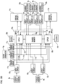
- FIG. 1 is a circuit configuration diagram of an electric driving apparatus according to Embodiment 1 of the present invention
- FIG. 1 represents the case where the electric driving apparatus is configured as an electric power steering apparatus.
- an electric power steering apparatus 100 includes a control unit 1, an electric motor (simply referred to as a motor, hereinafter) 2 formed of a three-phase brushless motor or the like, a control circuit unit 4, a first rotation sensor 9a, and a second rotation sensor 9b.
- the control unit 1 has double redundant systems that are configured in the same manner; the control unit 1 includes the control circuit unit 4 equipped with a first MPU 10a and a second MPU 10b, a first inverter circuit 3a, a second inverter circuit 3b, a first power-source relay 5a connected with the high-voltage DC terminal of the first inverter circuit 3a, and a second power-source relay 5b connected with the high-voltage DC terminal of the second inverter circuit 3b.
- Each of the first inverter circuit 3a and the second inverter circuit 3b is a three-phase inverter circuit formed of a three-phase bridge circuit.
- a battery 6 mounted in a vehicle supplies a DC power source to the control unit 1; by means of an ignition switch 7, a DC power source from the battery 6 is applied to the control circuit unit 4 by way of a power-supply circuit 13.
- information pieces for example, from a torque sensor that is mounted in the vicinity of a handwheel and detects steering torque, a speed sensor that detects the traveling speed of a vehicle, and the like are inputted from a sensor 8 to the control circuit unit 4.
- the first inverter circuit 3a includes U-phase, V-phase, and W-phase arms that are connected in parallel with one another.
- the U-phase arm is formed of a series connection member consisting of a U-phase upper arm and a U-phase lower arm;
- the V-phase arm is formed of a series connection member consisting of a V-phase upper arm and a V-phase lower arm;
- the W-phase arm is formed of a series connection member consisting of a W-phase upper arm and a W-phase lower arm.
- the U-phase upper arm has a U-phase upper arm switching device 31U; the U-phase lower arm has a U-phase lower arm switching device 32U; the V-phase upper arm has a V-phase upper arm switching device 31V; the V-phase lower arm has a V-phase lower arm switching device 32V; the W-phase upper arm has a W-phase upper arm switching device 31W; the W-phase lower arm has a W-phase lower arm switching device 32W.
- shunt resistors 33U, 33V, and 33W for detecting an electric current are connected in series with the U-phase lower arm switching device 32U, the V-phase lower arm switching device 32V, and the W-phase lower arm switching device 32W, respectively.
- Noise suppression capacitors 30U, 30V, and 30W are connected in parallel with the U-phase arm, the V-phase arm, and the W-phase arm, respectively.
- the shunt resistors are disposed not in all of the three phases but in two specific phases among the three phases; or it may be allowed that only a single shunt resistor is disposed in the bus bar of the battery line.
- the second inverter circuit 3b includes U-phase, V-phase, and W-phase arms that are connected in parallel with one another.
- the U-phase arm is formed of a series connection member consisting of a U-phase upper arm and a U-phase lower arm;
- the V-phase arm is formed of a series connection member consisting of a V-phase upper arm and a V-phase lower arm;
- the W-phase arm is formed of a series connection member consisting of a W-phase upper arm and a W-phase lower arm.
- the U-phase upper arm has a U-phase upper arm switching device 36U; the U-phase lower arm has a U-phase lower arm switching device 37U; the V-phase upper arm has a V-phase upper arm switching device 36V; the V-phase lower arm has a V-phase lower arm switching device 37V; the W-phase upper arm has a W-phase upper arm switching device 36W; the W-phase lower arm has a W-phase lower arm switching device 37W.
- shunt resistors 38U, 38V, and 38W for detecting an electric current are connected in series with the U-phase lower arm switching device 37U, the V-phase lower arm switching device 37V, and the W-phase lower arm switching device 37W, respectively.
- Noise suppression capacitors 35U, 35V, and 35W are connected in parallel with the U-phase arm, the V-phase arm, and the W-phase arm, respectively.
- the shunt resistors are disposed not in all of the three phases but in two specific phases among the three phases; or it may be allowed that only a single shunt resistor is disposed in the bus bar of the battery line.
- the motor 2 has two groups of stator windings, i.e., a first stator winding 2a and a second stator winding 2b in the stator thereof.
- the first stator winding 2a is formed of a three-phase stator winding including U1-phase, V1-phase, and W1-phase windings that are ⁇ -connected.
- the second stator winding 2b is formed of a three-phase stator winding including U2-phase, V2-phase, and W2-phase windings that are ⁇ -connected.
- the rotor (not illustrated in FIG. 1 ) of the motor 2 has a plurality of magnetic-field poles formed of permanent magnets, as described later.
- the motor 2 is not necessarily a brushless motor having a three-phase delta-connected stator winding; it may have a three-phase star-connected stator winding; moreover, it may not necessarily be a three-phase motor but be a motor of two or more phases other than three phases.
- the mutual connection point between the U1-phase winding and the V1-phase winding of the first stator winding 2a is connected, through the U-phase motor relay switching device 34U, with the mutual connection point between the U-phase upper arm switching device 31U and the U-phase lower arm switching device 32U of the first inverter circuit 3a.
- the mutual connection point between the V1-phase winding and the W1-phase winding of the first stator winding 2a is connected, through the V-phase motor relay switching device 34V, with the mutual connection point between the V-phase upper arm switching device 31V and the V-phase lower arm switching device 32V of the first inverter circuit 3a.
- the mutual connection point between the W1-phase winding and the U1-phase winding of the first stator winding 2a is connected, through the W-phase motor relay switching device 34W, with the mutual connection point between the W-phase upper arm switching device 31W and the W-phase lower arm switching device 32W of the first inverter circuit 3a.
- the mutual connection point between the U2-phase winding and the V2-phase winding of the second stator winding 2b is connected, through the U-phase motor relay switching device 39U, with the mutual connection point between the U-phase upper arm switching device 36U and the U-phase lower arm switching device 37U of the second inverter circuit 3b.
- the mutual connection point between the V2-phase winding and the W2-phase winding of the second stator winding 2b is connected, through the V-phase motor relay switching device 39V, with the mutual connection point between the V-phase upper arm switching device 36V and the V-phase lower arm switching device 37V of the second inverter circuit 3b.
- the mutual connection point between the W2-phase winding and the U2-phase winding of the second stator winding 2b is connected, through the W-phase motor relay switching device 39W, with the mutual connection point between the W-phase upper arm switching device 36W and the W-phase lower arm switching device 37W of the second inverter circuit 3b.
- the positive-polarity DC terminal 3ap of the first inverter circuit 3a is connected with the positive-polarity terminal of the battery 6 mounted in the vehicle, by way of the first power-source relay 5a formed of switching devices and a smoothing circuit 40 including a smoothing reactor 41 and a smoothing capacitor 42.
- the positive-polarity DC terminal 3bp of the second inverter circuit 3b is connected with the positive-polarity terminal of the battery 6 mounted in the vehicle, by way of the second power-source relay 5b formed of switching devices and the smoothing circuit 40.
- Each of the negative-polarity DC terminal 3an of the first inverter circuit 3a and the negative-polarity DC terminal 3bn of the second inverter circuit 3b is connected with the negative-polarity terminal of the battery 6, by way of the ground potential position of the vehicle.
- the switching devices of the first power-source relay 5a are included in the first inverter circuit 3a; it may be allowed that the switching devices of the second power-source relay 5b are included in the second inverter circuit 3b.
- the first inverter circuit 3a and the second inverter circuit 3b each have a single and the same circuit configuration and can independently supply respective electric currents to the first stator winding 2a and the second stator winding 2b of the motor 2.
- the control circuit unit 4 has the power-supply circuit 13 connected with the positive-polarity terminal of the battery 6 by way of the ignition switch 7, the first MPU 10a, the second MPU 10b, a first driving circuit 11a, a second driving circuit 11b, an input circuit 12 to which various kinds of information pieces from the sensor 8 are inputted, and a notification output circuit 16 that activates a notification means 15 such as a lamp when an abnormality occurs in the control circuit unit 4 or the like.
- the first driving circuit 11a provides respective driving signals to the switching devices 31U, 31V, 31W, 32U, 32V, and 32W of the first inverter circuit 3a so as to drive these switching devices.
- the second driving circuit 11b provides respective driving signals to the switching devices 36U, 36V, 36W, 37U, 37V, and 37W of the second inverter circuit 3b so as to drive these switching devices.
- the sensor 8 collectively denotes various kinds of sensors, described later;
- the information pieces from the sensor 8 include, for example, information pieces from a torque sensor that is mounted in the vicinity of a handwheel and detects steering torque, a speed sensor that detects the traveling speed of a vehicle, and the like, the respective potential differences across the shunt resistors 33U, 33V, and 33W of the first inverter circuit 3a, the respective potential differences across the shunt resistors 38U, 38V, and 38W of the second inverter circuit 3b, the respective inter-terminal voltages of the first stator winding 2a of the motor 2, and the respective inter-terminal voltages of the second stator winding 2b;
- the sensor 8 transmits these information pieces to the input circuit 12, and then the input circuit 12 transmits them to the first MPU 10a and the second MPU 10b.
- the first MPU 10a calculates a target current value to be supplied to the first stator winding 2a of the motor 2, calculates respective differences between the calculated target current value and the respective potential differences across the shunt resistors 33U, 33V, and 33W of the first inverter circuit 3a, and controls the output of a first output circuit including the first driving circuit 11a and the first inverter circuit 3a, based on the differences, in such a way as to perform feedback control; as a result, a desired motor current is supplied to the first stator winding 2a.
- the second MPU 10b calculates a target current value to be supplied to the second stator winding 2b of the motor 2, calculates respective differences between the calculated target current value and the respective potential differences across the shunt resistors 38U, 38V, and 38W of the second inverter circuit 3b, and controls the output of a second output circuit including the second driving circuit 11b and the second inverter circuit 3b, based on the differences, in such a way as to perform feedback control; as a result, a desired motor current is supplied to the second stator winding 2b.
- the motor 2 generates desired assist torque based on the respective motor currents supplied to the first stator winding 2a and the second stator winding 2b and assists the steering power of a driver.
- the first MPU 10a can control the switching devices of the first power-source relay 5a, the U-phase motor relay switching device 34U, the V-phase motor relay switching device 34V, and the W-phase motor relay switching device 34W in the first inverter circuit 3a, and the switching devices 31U, 31V, 31W, 32U, 32V, and 32W for the first stator winding 2a.
- the first power-source relay 5a When the first power-source relay 5a is turned off, supply of an electric current from the first inverter circuit 3a to the first stator winding 2a of the motor 2 is cut off.
- the second MPU 10b can control the switching devices of the second power-source relay 5b, the U-phase motor relay switching device 34U, the V-phase motor relay switching device 34V, and the W-phase motor relay switching device 34W in the first inverter circuit 3a, and the switching devices 36U, 36V, 36W, 37U, 37V, and 37W for the second stator winding 2b.
- the first power-source relay 5a When the first power-source relay 5a is turned off, supply of an electric current from the first inverter circuit 3a to the first stator winding 2a of the motor 2 is cut off.
- the first MPU 10a has an abnormality detection function of detecting an abnormality in the first inverter circuit 3a, the first stator winding 2a of the motor 2, or the like, based on the various information pieces inputted from the sensor 8; when any abnormality is detected, for example, the first MPU 10a turns off the switching device, corresponding to the winding of a predetermined phase, among the first motor relay switching devices 34U, 34V, and 34W in order to cut off only supply of the electric current for the winding, of the predetermined phase, in the first stator winding 2a, or turns off the first power-source relay 5a, depending on the abnormality.
- the second MPU 10b has an abnormality detection function of detecting an abnormality in the second inverter circuit 3b, the second stator winding 2b of the motor 2, or the like, based on the various information pieces inputted from the sensor 8; when any abnormality is detected, for example, the second MPU 10b turns off the switching device, corresponding to the winding of a predetermined phase, among the second motor relay switching devices 39U, 39V, and 39W in order to cut off only supply of the electric current for the winding, of the predetermined phase, in the second stator winding 2b, or turns off the second power-source relay 5b, depending on the abnormality.
- first and second MPUs 10a and 10b each detect an abnormality, as described above, at least one of the first and second MPUs 10a and 10b outputs a command for, for example, lighting a lamp as the notification means 15.
- the motor 2 is a brushless motor having two groups of three-phase delta-connected stator windings and a plurality of magnetic-field poles in the rotor thereof.
- the motor 2 is equipped with the first rotation sensor 9a and the second rotation sensor 9b for detecting the rotation position of the rotor.
- Two sensors, i.e. , the first rotation sensor 9a and the second rotation sensor 9b are provided in order to secure the redundant system in the control system; respective rotation position information pieces, from the first rotation sensor 9a and the second rotation sensor 9b, that each indicate the rotation position of the rotor are transmitted to the input circuit 12 of the control circuit unit 4.
- the first MPU 10a and the second MPU 10b are connected with each other through a communication line 14 so that they can mutually and periodically transmit and receive data and information which are predetermined-format communication signals.
- the first MPU 10a can understand the condition of the second MPU 10b, and vice versa.
- this information can be transmitted to the second MPU 10b.
- the periodic predetermined-format communication signal can neither be transmitted nor be received; thus, one of the MPUs can detect the fact that an abnormality has occurred in the other one of the MPUs.
- control unit 1 has double redundant systems; each of the systems independently performs information inputting and calculation, and outputs a control amount for driving the motor 2.
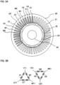
- FIG. 2A is a transverse cross-sectional view of the motor in the electric driving apparatus according to Embodiment 1 of the present invention
- FIG. 2B is a set of circuit diagrams illustrating the stator windings of the motor in the electric driving apparatus according to Embodiment 1 of the present invention.
- a stator 20 in which forty-eight slots 21 are formed in the inner circumference portion thereof is configured with stacked thin-plate steel sheets.
- a rotor 23 is disposed in the inner space of the stator 20 in such a way as to be coaxial with the stator 20.
- Eight (eight poles) magnetic-field poles 22 formed of a permanent magnet are arranged at predetermined positions on the outer circumference portion of the rotor 23 in such a way that the N-pole and the S-pole are alternately arranged.
- An output axle 24 is fixed in the center portion of the rotor 23; a gear (unillustrated) is disposed in one of the axis-direction ends of the output axle 24 so that driver's steering of the handwheel can be assisted.
- Two or more, for example, four coil conductors are inserted into each of the slots 21.
- the respective coil conductors of the U1-phase winding, the V1-phase winding, the W1-phase winding are connected with one another at the portion extending from the slot 21 to each of the both axis-direction ends of the stator 20 and the respective coil conductors of the U2-phase winding, the V2-phase winding, the W2-phase winding are connected with one another at the portion extending from the slot 21 to each of the axis-direction both ends of the stator 20, so that the three-phase delta-connected first stator winding 2a and the three-phase delta-connected second stator winding 2b, illustrated in FIG. 2B , are formed.
- the coil conductors of the V1-phase winding, the W1-phase winding belonging to the first system and the coil conductors of the U2-phase winding, the V2-phase winding, and the W2-phase winding belonging to the second system are inserted into the respective slots 21 in the same manner as the coil conductor of the U1-phase winding.
- the coil conductors of the U1-phase winding and the U2-phase winding are inserted into the respective adjacent slots; the coil conductors of the V1-phase winding and the V2-phase winding are inserted into the respective adjacent slots; the coil conductors of the W1-phase winding and the W2-phase winding are inserted into the respective adjacent slots.
- the coil conductor of the U2-phase winding belonging to the second system is inserted into the slot that is adjacent to the slot into which the coil conductor of the U1-phase winding is inserted;
- the coil conductor of the V1-phase winding belonging to the first system is inserted into the slot that is adjacent to the slot into which the coil conductor of the U2-phase winding is inserted;
- the coil conductor of the V2-phase winding belonging to the second system is inserted into the slot that is adjacent to the slot into which the coil conductor of the V1-phase winding is inserted;
- the coil conductor of the W1-phase winding belonging to the first system is inserted into the slot that is adjacent to the slot into which the coil conductor of the V2-phase winding is inserted;
- the coil conductor of the W2-phase winding belonging to the second system is inserted into the slot that is adjacent to the slot into which the coil conductor of the W1-phase winding is inserted.
- the coil conductors of the windings of the respective phases belonging to the first system or the second system are regularly inserted into the slots 21 in the foregoing order and are wound around the stator 20.
- the coil conductors of the windings of the respective phases belonging to the first system or the second system are wound around the stator 20 in the manner of a distributed winding, as described above.
- the terminal ends of the coil conductors of the respective phases are connected with one another in such a way that the first stator winding 2a and the second stator winding 2b that are delta-connected for the first system and the second system, respectively, are configured.
- a winding end portion U11 in which the connection portion between the coil conductor of the U1-phase winding and the coil conductor of the V1-phase winding is extended is connected with the U-phase motor relay switching device 34U of the first inverter circuit 3a in FIG. 1 ; similarly, a winding end portion V11 is connected with the motor relay switching device 34V and a winding end portion W11 is connected with the motor relay switching device 34W.
- a winding end portion U21 in which the connection portion between the coil conductor of the U2-phase winding and the coil conductor of the V2-phase winding is extended is connected with the motor relay switching device 39U of the second inverter circuit 3b in FIG. 2 ; similarly, a winding end portion V21 is connected with the motor relay switching device 39V and a winding end portion W21 is connected with the motor relay switching device 39W.
- the first stator winding 2a and the second stator winding 2b are configured in such a way that there exists a phase difference of 30° [electric angle] therebetween.
- each of the inverter circuits is utilized with a modulation rate of 100% or higher, an electric angle 6th-order radial-direction output fluctuation occurs in the motor 2 for each of the systems; however, when the first inverter circuit 3a and the second inverter circuit 3b energize the first stator winding 2a and the second stator winding 2b, respectively, and the outputs of the first system and the second system are summed up through the motor 2, the electric angle 6th-order output fluctuations of the respective systems are canceled out in the motor, as a whole.
- control circuit unit 4 includes only a single MPU and a single CPU provided in the MPU, the control amount calculated by the single MPU is outputted to the inverter circuit of one of the two systems without changing the phase of the control amount, and a control amount is calculated by adding 30° to the foregoing calculated control amount and outputted to the inverter circuit of the other one of the two systems; as a result, the electric angle 6th-order output fluctuations of the respective systems can be canceled out in the motor, as a whole.
- Embodiment 1 of the present invention in which the redundancy of the control system is considered and hence the control circuit unit 4 has two independent MPUs, i.e., the first MPU 10a and the second MPU 10b and in which each of the MPUs has a single independent CPU, it is necessary that there exists a phase difference between the output of the first MPU 10a and the output of the second MPU 10b. In order to reduce a ripple causes by the phase difference between the respective outputs of the two MPUs, it is required to synchronize the respective outputs of the two MPUs; this matter will be described later.
- an electric driving apparatus having a motor in which there exists a phase difference of 30° between the first system and the second system so that the electric angle 6th-order output fluctuations can be canceled out; for example, when m systems are provided and, in order to cancel out the electric angle nth-order output fluctuations, a phase difference of [360/m/n] ° is provided between the m respective systems, the same effect is obtained.
- stator winding is made through a distributed winding method; however, even when the stator winding is made through a method other than a distributed winding method, the same effect is obtained, as long as the respective stator windings are electrically coupled with each other.
- FIG. 3A is a configuration diagram representing a control circuit unit including MPUs in the electric driving apparatus according to Embodiment 1 of the present invention.
- the first MPU 10a includes a first CPU 10c, which is a first calculation means, and a first direct memory access (referred to as a DMA, hereinafter) 10e, which is a memory means that operates independently from the processing in the first CPU 10c.
- the first CPU 10c performs processing of all the programs, based on a clock signal from a first clock 10h.
- the second MPU 10b includes a second CPU 10d, which is a second calculation means, and a second DMA 10f, which is a memory means that operates independently from the processing in the second CPU 10d.
- the second CPU 10d performs processing of all the programs, based on a clock signal from a second clock 10i.
- the first clock 10h and the second clock 10i generate respective clock signals, having a single and the same period, that are the references for the processing steps.
- Vehicle speed information from a vehicle speed sensor 8a is directly inputted to the first MPU 10a and the second MPU 10b by way of a first input circuit 12a.
- a torque signal from a torque sensor 8b is independently inputted to the first DMA 10e and the second DMA 10f by way of two independent input circuits, i.e., second and third input circuits 12b and 12c, respectively.
- a first current sensor 33a detects electric currents of the respective phases, based on the respective voltages across the shunt resistors 33U, 33V, and 33W provided for the respective phases of the first inverter circuit 3a in FIG. 1 ; first current detection information obtained through the detection is inputted to the first DMA 10e and the second DMA 10f by way of a fourth input circuit 12d.
- a second current sensor 33b detects electric currents of the respective phases, based on the respective voltages across the shunt resistors 38U, 38V, and 38W provided for the respective phases of the second inverter circuit 3b in FIG. 1 ; second current detection information obtained through the detection is inputted to the first DMA 10e and the second DMA 10f by way of a fifth input circuit 12e.
- first rotation position information from the first rotation sensor 9a is inputted to the first DMA 10e by way of a sixth input circuit 12f.
- Second rotation position information from the second rotation sensor 9b is inputted to the second DMA 10f by way of a seventh input circuit 12g.
- Respective trigger signals outputted from a first trigger circuit 17a, a second trigger circuit 17b, and a third trigger circuit 17c are inputted to the first CPU 10c, the second CPU 10d, the first DMA 10e, and the second DMA 10f, through lines 17d, 17e, and 17f.
- the period of the trigger signal outputted from the third trigger circuit 17c is set to be the shortest; the period of the trigger signal outputted from the second trigger circuit 17b is set to be the second shortest; the period of the trigger signal outputted from the first trigger circuit 17a is set to be the longest.
- Information pieces inputted from corresponding sensors to the first DMA and the second DMA 10f are especially important in terms of control; thus, these information pieces will be referred to as specific information pieces. These specific information pieces are divided into two groups and are stored in memories in accordance with the trigger signal outputted from the first trigger circuit 17a or the second trigger circuit 17b.
- the information pieces to be stored based on the trigger signal from the second trigger circuit 17b, among the three trigger circuits, that outputs a trigger signal having the second shortest period are the first current detection information, the second current detection information, the first rotation position information, and the second rotation position information.
- the information to be stored based on the trigger signal from the first trigger circuit 17a, among the three trigger circuits, that outputs the trigger signal having the longest period is torque information.
- connection may be made in such a way that the respective input information pieces are stored based on the trigger signal from the second trigger circuit 17b that outputs a trigger signal having the second shortest period or the trigger signal from the third trigger circuit 17c that outputs a trigger signal having the shortest period.
- the respective information pieces are concurrently stored in accordance with the trigger signals; thus, a single and the same information value can be stored in the first DMA 10e and the second DMA 10f.
- the first CPU 10c and the second CPU 10d receive various kinds of information pieces stored in the first DMA 10e and the second DMA 10f. Because separately from the processing in the first CPU 10c and the second CPU 10d, various kinds of information pieces are independently stored in the first DMA 10e and the second DMA 10f, the various kinds of information pieces can concurrently be stored without interfering with the program processing in the first CPU 10c and the second CPU 10d.
- the respective trigger signals outputted from the first trigger circuit 17a, the second trigger circuit 17b, and the third trigger circuit 17c are inputted also to the first CPU 10c and the second CPU 10d; the first CPU 10c and the second CPU 10d each perform predetermined processing in accordance with these trigger signals.
- This processing makes it possible that the first CPU 10c and the second CPU 10d concurrently perform a single and the same processing; thus, the CPU processing steps can be synchronized with each other.
- the contents of the concurrent processing based on the earliest trigger signal from the third trigger circuit 17c correspond to the output of a PWM command signal for practically controlling the first driving circuit 11a and the second driving circuit 11b.
- the period of the trigger signal from the third trigger circuit 17c indicates the carrier period of the PWM signal
- the first CPU 10c and the second CPU 10d can concurrently perform outputting in synchronization with the trigger signal from the third trigger circuit 17c, in response to the output of the PWM command signal. That is to say, there can be prevented the problem that when the method disclosed in Patent Document 2 is utilized without synchronization, the effect of a switching pulse caused in the PWM signal of another group enlarges a current detection error.
- the fact that concurrent outputting can be performed suggests that for one of the CPUs, the other one of the CPUs can readily shift the timing of its output by a predetermined time or a predetermined phase.
- Embodiment 1 represented in FIG. 3A the generation of the foregoing three kinds of trigger signals having different periods, i.e., the respective trigger signals from the first trigger circuit 17a, the second trigger circuit 17b, and the third trigger circuit 17c, is performed in the following manner: a clock generator 17g is disposed and a clock from the clock generator 17g is inputted to the first trigger circuit 17a, the second trigger circuit 17b, and the third trigger circuit 17c that each have a predetermined frequency divider; the trigger signals are generated by dividing the clock from the clock generator 17g by means of the respective frequency dividers.
- the clock generator 17g can be replaced by any one of the first clock 10h and the second clock 10i.
- a period signal can directly be outputted through one of the output ports of any one of the first CPU 10c and the second CPU 10d (this case is indicated by a broken line 17h in FIG. 3A ).
- the first CPU 10c is set to be a parent CPU
- the second CPU 10d is set to be a child CPU, which is subordinate to the parent CPU.
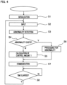
- FIG. 4 is a main flowchart representing the operation of the CPU in the electric driving apparatus according to Embodiment 1 of the present invention. Because the first CPU 10c performs almost the same processing as the second CPU 10d performs, the processing of the first CPU 10c, as an example, will be explained.
- the information pieces include not only the specific information obtained through the first DMA but communication data of the second CPU 10d, which is a partner, and ordinary information such as a vehicle speed.
- processing of detecting an abnormality is performed.
- two methods i.e., a method in which the switching devices in the first inverter circuit 3a are driven and the flowing electric currents are detected by use of the shunt resistors 33U, 33V, and 33W so that an abnormality is detected and a method in which the winding terminal voltage of the motor 2 is monitored so that it is checked whether or not respective predetermined voltages appear in accordance with the drive of the switching devices.
- the difference between the detection current value and the target current value is not minimized even after a predetermined time elapses, it may be determined that an abnormality has occurred, because electric leakage may have occurred.
- the respective voltages and currents are monitored so that an abnormality is detected, the abnormality, even in a single phase, can be detected. Then, whether or not an abnormality exists and the state of the abnormality are stored.
- step S4 whether or not the detection of an abnormality has occurred is checked.
- a normal control amount is calculated in the step S5.
- abnormality processing is performed in the step S6 in accordance with the abnormality. For example, in the case of an open-failure in the upper-arm or lower-arm switching device of the first inverter circuit 3a, control-amount calculation is performed in such a way that at least any one of the motor relay switching devices 34U through 34W is turned off or that driving is performed by the switching devices of two normal phases.
- the abnormality processing includes processing in which in the case of a short-circuit failure, at least any one of the motor relay switching devices 34U through 34W is turned off and processing in which in the case of a double failure, a short-to-power failure of the motor winding, a short-to-ground failure thereof, or the like, all the switching devices including the first power-source relay 5a and the second power-source relay 5b are turned off.
- a normal-time control amount is calculated in the step S5.
- the method therefor is the same as that in a conventional apparatus; based on the torque sensor and a vehicle speed, a target current value is calculated; a current detection value is compared with the target current value; then, based on the difference therebetween, a control command value is calculated.
- the step S5 is followed by the step S7, where the first CPU 10c outputs communication information in order to provide information to and receive information from the partner CPU, i.e., the second CPU 10d, here. It is made possible to utilize this communication information in order to transmit not only the state of an abnormality but, for example, input information and specific information, to receive the same information from the partner CPU, and to ascertain that no difference therebetween.
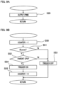
- FIGS. 5A, 5B, and 5C are sub-flowcharts representing the operation of the CPU in the electric driving apparatus according to Embodiment 1 of the present invention.
- the sub-flow in each of FIGS. 5A, 5B, and 5C operates in a period that is shorter than that of the main flow in FIG. 4 ; after processing is performed in the sub-flow every predetermined period, the main flow is resumed again; in other words, the same operation as interrupt processing is performed.
- the processing in FIG. 5A is implemented based on the trigger signal from the third trigger circuit 17c in FIG. 3A , i.e., implemented in the shortest period. For example, the processing is implemented every 50 [ ⁇ s].
- the step S20 in accordance with the duty value of the PWM command signal, which is a control amount that has already been stored, the PWM command signal is outputted.
- the first CPU 10c and the second CPU 10d can output respective command signals that are synchronized with each other by the trigger signal from the third trigger circuit 17c. Because this is outputting processing in accordance with the shortest period, it is not advisable that processing that requires another time is inserted thereinto; thus, only the outputting processing is implemented, here.
- the processing in FIG. 5B is implemented in accordance with the trigger signal from the second trigger circuit 17b.
- This period is, for example, 200[ ⁇ s], i.e., integer-fold as large as the carrier period of the PWM.
- specific information pieces are obtained from the first DMA 10e.
- the specific information pieces at least two kinds of information pieces, i.e., the value of the first current detection information and the value of the first rotation position information are required.
- the target current value calculated in the main flow and the like is required and hence is obtained.
- a control amount is calculated again; the control amount is converted into a PWM amount and then is stored.
- this calculation method is implemented in such a way that a voltage command value is calculated in a biaxial (d-axis, and q-axis) coordinate system, for example, based on the difference between the target voltage value and the detection current value; then, the voltage command value in the biaxial coordinate system is converted into respective values of U, V, and W phases, based on a rotation sensor information value.
- the voltage command value is calculated in such a manner as the method disclosed in Patent Document 3.
- the control amount for the PWA command signal in FIG. 5A can be stored.
- the difference between the control amount calculation in the step S31 and the control amount calculation 1 in the step S5 of the main flow in FIG. 4 is not only that in the re-calculation of the control amount in the step S31 of FIG. 5B , the specific information is the latest but also that the control amounts related to information pieces, such as the vehicle speed and the like, that change, for example, only in the main flow are not calculated but a stored result is utilized so that the calculation processing time is shortened.
- the processing in FIG. 5C is implemented in accordance with the period of the trigger signal from the first trigger circuit 17a, i.e., implemented in the longest period.
- the processing is implemented in accordance with the trigger signal having a period of 1[ms], i.e., implemented in accordance with the trigger signal having a period that is integer-fold as large as the period of the trigger signal from the second trigger circuit 17b.
- specific information is obtained.
- the specific information is torque information, with which the demanded torque can be known.
- the target current value is calculated. This calculation method is the same as that in a conventional apparatus; the target current value for performing assistance is calculated and stored by utilizing the specific information, the vehicle speed, the rotation speed information from the rotation sensor, and the like.
- the trigger processing steps in FIGS. 5A, 5B, and 5C make it possible to calculate the target current value in a period of 1[ms], to calculate the control amount every 200 [ ⁇ s], and to output the control amount every 50 [ ⁇ s].
- These trigger signals make it possible to secure synchronization between the first MPU 10a and the second MPU 10b. That is to say, because the synchronization between the two MPUs can be secured in a period that is shorter than the period of 5 [ms] in the main flow represented in FIG. 4 , it is not necessarily required to secure synchronization in the main flow.
- the synchronization can be secured with the output having the shortest period, it is easy to secure a phase difference between the respective outputs of the two MPUs; thus, as is the case where phase differences are provided between the respective phases, it is made possible to provide desired phase differences even in the case of driving of the other system.
- the electric driving apparatus makes it possible that based on the trigger signals from the trigger circuit, synchronization between the respective output timings of PWMs, which are outputs thereof, of the two MPUs and that the two MPUs can concurrently secure a single and the same value of the specific information. Accordingly, even in the case where with regard to motor windings illustrated in FIGS.
- interference lies between the first stator winding and the second stator winding, the respective demanded torque values of the two systems are equal to each other; based on this fact, the respective target voltage values are equal to each other and the respective voltage command values are equal to each other; moreover, a voltage command value can be obtained based on a phase difference; furthermore, the respective PWM outputs can prevent the control noise signals caused by the switching devices of the two systems from deteriorating the current-detection accuracy.
- FIG. 3B is a configuration diagram representing an variant example of the control circuit unit including MPUs in the electric driving apparatus according to Embodiment 1 of the present invention.
- the configuration of the variant example represented in FIG. 3B differs from the configuration represented in FIG. 3A in that a different memory means is included in the first MPU 10a and the second MPU 10b.
- the first MPU 10a includes a shared memory 10g that can be accessed by the first CPU 10c and the second CPU 10d.
- the second MPU 10b includes the shared memory 10g that can be accessed by the first CPU 10c and the second CPU 10d. It may be considered that in this configuration, the first DMA 10e and the second DMA 10f are replaced by the shared memory 10g; thus, it goes without saying that an effect the same as that of the configuration in FIG. 3A can be obtained.
- FIG. 6A is a transverse cross-sectional view of a motor in an electric driving apparatus according to Embodiment 2 of the present invention
- FIG. 6B is a circuit diagram representing the stator windings of the motor in the electric driving apparatus according to Embodiment 2 of the present invention.
- the circuit diagram, in FIG. 1 of Embodiment 1 is applied to Embodiment 2.
- the same reference characters denote the same or similar portions.
- FIG. 6A is a drawing corresponding to FIG. 2A for Embodiment 1. In the following explanation, the difference from Embodiment 1 will mainly be explained.
- a stator 20 in which twelve slots 21 are arranged in the inner circumference portion thereof is configured with stacked thin-plate steel sheets.
- a rotor 23 is disposed in the center of the stator 20 in such a way as to be coaxial with the stator 20; ten magnetic-field poles 22 formed of a permanent magnet are arranged on the outer circumference portion of the rotor 23 in such a way that the N-pole and the S-pole are alternately arranged.
- An output axle 24 is extended in the center of the rotor 23; a gear is disposed in one of the axis-direction ends of the output axle 24 so that steering of the handwheel is assisted.
- FIG. 6B A great number of coils are arranged in the slots 21; the coil extending from the slot 21 is wound.
- Pat of the winding state of the coil is illustrated in FIG. 6B .
- two groups of three-phase windings are formed; however, the winding of the first system and the winding of the second system are arranged in the respective slots that are apart from each other.
- the U1-phase coil there is illustrated coils inserted into the respective slots that are adjacent to each other and flank one tooth.
- the U1-phase coil is wound in a concentrated manner around one of the adjacent teeth; in the vicinity of this tooth, the V1-phase coil and the W1-phase coil are wound in that order.
- FIG. 6B represents a circuit diagram of the coil windings.
- the coil windings are wound in a concentrated manner; the respective terminal ends are connected with one another in such a way as to form a star connection; the respective ends of the extended portions are connected with the corresponding motor relay switching devices of the inverter circuit in FIG. 1 . Accordingly, each system has three terminal ends, and the respective terminal ends are independently connected with the inverter circuit.
- FIG. 7 is a configuration diagram representing a control circuit unit including MPUs in the electric driving apparatus according to an example not forming part of the invention.
- FIG. 7 corresponds to FIG. 3 for Embodiment 1.
- the trigger circuits in Embodiment 1 are removed, and a trigger signal 17i is outputted from the first CPU 10c.
- a pull-up resistor 10j and a pull-down resistor 10k it can automatically be determined that the first CPU 10c and the second CPU 10d are a parent CPU that outputs the trigger signal and a child CPU that receives the trigger signal, respectively.
- the first and second DMAs in Embodiment 1 are also removed; each of the input information pieces is directly inputted to the first and second CPUs.
- FIG. 8 is a main flowchart representing the operation of the CPU in the electric driving apparatus according to an example not forming part of the invention
- FIG. 9A is a sub-flowchart representing the operation of the CPU in the electric driving apparatus according to an example not forming part of the invention
- FIG. 9B is a sub-flowchart representing the operation of the CPU in the electric driving apparatus according to an example not forming part of the invention
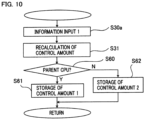
- FIG. 10 is a sub-flowchart representing the operation of the CPU in the electric driving apparatus according to an example not forming part of the invention.
- the first CPU 10c and the second CPU 10d have almost the same programs, the first CPU 10c will be explained, here. Because the steps having reference characters the same as those in FIGS. 4 and 5 of Embodiment 1 perform the same or similar processing items, the explanation therefor will be omitted, and the steps that are different from those in Embodiment 1 will mainly be explained.
- FIG. 8 the power is turned on; the step S1 for initialization is implemented; then, processing in a synchronization routine from the step S10 to the step S12 is implemented. This processing is not necessarily required; because it is more convenient to insert this processing into the main flow, it is indicated by broken lines.
- the step S10 it is checked whether the CPU is the parent CPU that outputs a trigger signal or the child CPU that receives the trigger signal.
- the trigger signal is outputted in the step S11, and then the step S11 is followed by the step S2; however, it may be allowed that some waiting time, for example, a step in which a time for the partner CPU, i.e., the second CPU 10d to receive the trigger signal is waited is inserted between the step S11 and the step S2.
- the step S12 in which a time for the child CPU to receive a signal from the partner CPU is waited is implemented.
- step S12 is followed by the step S2.
- the respective processing items of the first and second CPUs 10c and 10d are different from each other, depending on whether the first and second CPUs 10c and 10d are the parent CPU and the child CPU, respectively, and vice versa; however, the first and second CPUs 10c and 10d can synchronously perform the following processing.
- step S2 input information is obtained in the step S2; then, detection whether or not an abnormality exists is performed in the step S3. Subsequently, whether or not an abnormality exists is checked in the step S4; a normal-time control amount is calculated in the step S5 (a) ; then, processing for an abnormal time is performed in the step S6 (a) ; however, due to the difference in the motor stator windings in Embodiment 1, the calculation method may differ.
- step S5 (a) a target current is set, and the feedback amount based on the difference between the target current and a detection current value is calculated and stored. Also in the step S6(a), two-phase driving is continued or processing such as stopping driving in all phases is performed and stored. In the step S7, there is performed communication for one of the CPUs to notify the partner CPU of the state of its own. In the step S13, processing in the synchronization routine is implemented again. Because this processing is the same as the processing items in the steps S10 through S12 and is not necessarily required, it is represented by broken lines. In the step S8, waiting processing is implemented until a predetermined time elapses.
- single-time synchronization processing is implemented each time the power source is turned on.
- This method is obtained by integrating single-time synchronization processing with the normal processing routine.
- the first synchronization is implemented when the power source is turned on.
- the respective CPUs are synchronized with each other in each main flow (for example, every 5 [ms]); however, the synchronization needs not to be implemented in each main flow and may be implemented only once in a plurality of main flows.
- This synchronization results in the situation that the two CPUs each utilize almost the same values, as the input information and the output information; for example, by, as the communication processing, communicating the respective input information pieces or the output information pieces as the calculation results to the partner CPUs, the two CPUs can compare the information pieces and detect abnormalities.
- the communication signal in the step S7 can be utilized; at first, the parent CPU outputs a transmission signal.
- the child CPU receives the communication signal from the partner CPU and then performs driving so as to output the transmission signal; the parent CPU receives the transmission signal from the child CPU so that synchronization can be implemented by use of the transmission signal.
- the discrimination between the parent CPU and the child CPU can readily be implemented by recognizing the CPUs through pull-up and pull-down hardware configurations represented in FIG. 7 . By use of the communication line, the number of input and output ports for the synchronization can be reduced.
- FIG. 9A is a sub-flowchart representing the operation of the CPU in the electric driving apparatus according to an example not forming part of the invention
- FIG. 9B is a sub-flowchart representing the operation of the CPU in the electric driving apparatus according to an example not forming part of the invention.
- the sub-flow represented in FIG. 9A is the same as that in FIG. 5A of Embodiment 1; in this sub-flow, outputting processing of the PWM is performed.
- FIG. 9B represents the flow.
- the sub-flow represented in FIG. 9B is processed in a period that is shorter than the period for the sub-flow represented in FIG. 9A , and is processed based on the first clock 10h and the second clock 10i represented in FIG. 7 .
- " 1 " is added to a first counter in the step S50.
- the first counter checks whether or not 50 [ ⁇ s] has elapsed. In the case where 50[ ⁇ s] has elapsed (Y), it is checked whether or not the CPU is the parent CPU in the step S52.
- the trigger signal is outputted in the step S54. After that, the value of the first counter is reset to "0". In the case where 50[ ⁇ s] has not elapsed (N) or in the case where the CPU is not the parent CPU (N), the trigger signal is turned off (not outputted) in the step S53.
- each of the parent and child CPUs performs the sub-flow represented in FIG. 9B ; however, in the case where the two CPUs each have a single and the same program, it is required to check whether each of them is the parent CPU or the child CPU.
- the step S55 in the sub-flow represented in FIG. 9B is followed by the sub-flow represented in FIG. 9A .
- each of them has a second counter (not represented), so that similar counting processing can be implemented.
- the sub-flow in FIG. 10 represents interrupt processing that is started, for example, every 200 [ ⁇ s], the respective counters for which are independently possessed by the two CPUs.
- the two CPUs may independently perform this interrupt processing; however, when performed based on the period of 50[us] represented in FIG. 9A or 9B , the period of the interrupt processing becomes integer-fold as large as this; thus, the respective interrupt processing steps of the two CPUs can be synchronized with each other.
- respective input information pieces are obtained in the step S30a. That is to say, as represented in FIG. 7 , a vehicle speed, a torque sensor value, a current detection value, and rotation position information are obtained.
- the control amount is calculated again, and the PWM duty value is stored.
- a phase difference between the respective outputs of the first system and the second system it is required to perform outputting with a predetermined phase difference. That is to say, it is checked whether the present system is the system of the parent CPU or the system of the child CPU. In the case where after the check, it is determined that the present system is the system of the parent CPU (Y), the value obtained in the step S31 is converted into a PWM value and is stored in the step S61. In contrast, in the case where the present system is the system of the child CPU (N), the step S60 is followed by the step S62. For example, in the case where the child CPU outputs the control amount with a phase difference of 180° from that of the parent CPU, a value obtained by making the calculated control amount include the phase difference of 180° is stored. After that, the main flow is resumed.
- the vehicle speed there may be utilized a value that is inputted and stored in a longer period, as is obtained in each main flow in Embodiment 1.
- it is required to calculate and store the latest control amount; it may be allowed that for that purpose, the respective latest values of only the current value and the rotation position information are obtained.
- Embodiment 1 in order to perform synchronization with 50 [ ⁇ s], which is the carrier period of the PWM, at least one system of a trigger signal is required; in comparison with Embodiment 1, the number of trigger signal systems can be reduced down to the minimum value; thus, the time management can rather readily be performed. It is made possible that two systems of trigger signals are provided and that the specific information (the current value and the rotation position), as the additional trigger signal, is synchronized and inputted.
- a predetermined control specification can readily be realized, even in the case of a motor having concentrated-winding stator windings.
- the other one of the systems which is normal, can independently continue the control; depending on the state of the abnormality, it is conceivable that the abnormal system continues driving of only two phases among three phases. Even in that case, as is the case with normal-time control, the normal system can continue controlling with a predetermined phase difference.
- first MPU 10a and the second MPU 10b are components independent from each other; it may be allowed that a single and the same package includes two independent CPUs, i.e., the first CPU 10c and the second CPU 10d. In the case of a multicore configuration, it may be allowed that when specific information is inputted from one of the CPUs to the other one of the CPUs and vice versa, the specific information is obtained not by use of the first DMA 10e and the second DMA 10f but through a memory that can commonly be accessed.
- an electric driving apparatus has an electric motor and a control unit for driving the electric motor
- synchronization of the outputs prevents switching, at the timing of current detection, that is caused by a difference between the carriers of the two groups; thus, it is made possible to prevent noise from providing an effect to the current detection.
- control command is outputted in a period that is the same as that of a PWM signal for supplying an electric current to each of the two groups of stator windings.
- synchronization of the PWM outputs prevents switching noise from providing an effect to current detection.
- the trigger signal outputted from the trigger circuit is formed of a single clock signal; said trigger signal is created from a clock signal different from a clock signal for driving each of the CPUs or is created based on a clock signal periodically outputted from one of the CPUs.
- the trigger signal is created based on some sort of clock output signal, so that two groups can be synchronized with each other.
- control command is calculated every timer period created in such a way as to be integer-fold as large as the period of the trigger signal outputted from the trigger circuit and then is stored.
- calculation of the control command is synchronized with the period of a trigger signal, so that it is made possible to synchronize respective updates of the control commands in the two groups.
- the respective CPUs each have a main flow to be processed in a predetermined period and a sub-flow to be processed in a predetermined period that is shorter than the predetermined period of the main flow, and in each processing according to the main flow and in each processing according to the sub-flow, the respective CPUs are synchronized with each other.
- the period of torque control performed in the main flow is longer than the period of current control performed in the sub-flow, so that stable torque control can be implemented.
- a plurality of the trigger circuits and among the plurality of information pieces inputted from the corresponding input circuits, specific information is synchronized with the trigger signal from the trigger circuit and is inputted to the respective CPUs, and then the respective CPUs each output a control command to the output circuit, based on the inputted specific information.
- control commands are created by use of input signals that are synchronized with each other, so that the output signals obtained from the two MPUs can be synchronized.
- the two Micro Processing Units each have an information input memory, take specific information among the plurality of information pieces into the information input memory every period, of a trigger signal, that is longer than the period of the trigger signal outputted from the trigger circuit to the output circuit, and output the control command to the output circuit every period, of a trigger circuit, that is the shortest.
- calculation is performed by use of intermediate variables that are synchronized with each other, so that even when there exists interference between the two groups of coil windings, the output signals obtained from the two MPUs can be synchronized with each other.
- the two Micro Processing Units have a shared memory and take specific information among the plurality of information pieces into the shared memory.
- a shared memory is utilized and hence calculation is performed by use of input values that are synchronized with each other, so that even when there exists interference between the two groups of coil windings, the output signals obtained from the two MPUs can be synchronized with each other.
- the two groups of stator windings have substantially no electric coupling therebetween, and the stator windings are independently supplied with respective electric currents or the respective electric currents are independently stopped from being supplied.
- the two groups of stator windings are each formed in a concentrated-winding manner.
- the two groups of stator windings have electric coupling therebetween and are independently supplied with respective electric currents or the respective electric currents are independently stopped from being supplied.
- non-interference control in the case where with a motor in which there exists interference between the groups, inputs are synchronized with each other and intermediate variables are synchronized with each other, non-interference control can normally be implemented.
- the two groups of stator windings are each formed in a distributed-winding manner.
- non-interference control in the case where with a distributed winding in which there exists electric coupling, inputs are synchronized with each other and intermediate variables are synchronized with each other, non-interference control can normally be implemented.
- a control device for an electric power steering apparatus wherein the electric power steering apparatus generates torque for assisting steering torque for a vehicle steering system, and wherein the electric driving apparatus as described above generates torque for assisting the steering torque.
- the present invention can be applied to the field of an electric driving apparatus, for example, an electric power steering apparatus that drives a driving subject by use of a motor, the field of the automobile industry, and the like.
Landscapes
- Engineering & Computer Science (AREA)
- Power Engineering (AREA)
- Chemical & Material Sciences (AREA)
- Combustion & Propulsion (AREA)
- Transportation (AREA)
- Mechanical Engineering (AREA)
- Control Of Ac Motors In General (AREA)
- Power Steering Mechanism (AREA)
- Control Of Electric Motors In General (AREA)
Claims (12)
- Elektrische Antriebseinrichtung mit einem Elektromotor (2) und einer Steuereinheit (1) zum Antreiben des Elektromotors (2),wobei der Elektromotor (2) einen einzelnen Rotor (23) und einen Stator (20) mit zwei unabhängigen Gruppen von Statorwicklungen (2a, 2b) aufweist,wobei die Steuereinheit (1) eine Eingabeschaltung (12), die eine Vielzahl von in der Berechnung zu verwendenden Informationen eingibt, zwei unabhängige Gruppen von Ausgabeschaltungen zum Ansteuern der zwei Gruppen von Statorwicklungen (2a, 2b) und zwei Mikroverarbeitungseinheiten (10a, 10b) enthält, die an die Ausgabeschaltungen Steuersignale auf der Grundlage von Steuerbeträgen ausgeben, die auf der Grundlage der in die Eingabeschaltung (12, 12a, 12b) eingegebenen Informationen berechnet werden,wobei die zwei Gruppen von Ausgabeschaltungen mindestens die zwei Gruppen von Statorwicklungen (2a, 2b) des Elektromotors (2) mit elektrischen Strömen versorgen oder die Versorgung mit elektrischem Strom unterbrechen können,wobei die zwei Mikroverarbeitungseinheiten (10a, 10b) jeweilige CPUs (10c, 10d) haben, miteinander kommunizieren können und jeweilige Anomalienerfassungsfunktionen zum Erfassen von Anomalien in den zwei Gruppen von Ausgabeschaltungen und den zwei Gruppen von Statorwicklungen (2a, 2b) haben; in dem Fall, in dem eine Anomalie in einer der zwei Gruppen von Ausgabeschaltungen oder einer der zwei Gruppen von Statorwicklungen (2a, 2b) erkannt wird, die Steuerung unter Verwendung der anderen der zwei Gruppen von Ausgabeschaltungen oder der anderen der zwei Gruppen von Statorwicklungen (2a, 2b), die normal sind, fortgesetzt wird;weiter dadurch gekennzeichnet, dassdie Steuereinheit (1) eine Vielzahl von Triggerschaltungen (17a, 17b, 17c) umfasst, wobei jede der Vielzahl von Triggerschaltungen (17a, 17b, 17c) ein jeweiliges Triggersignal mit einer unterschiedlichen jeweiligen Periode ausgibtwobei die jeweiligen Triggersignale, die aus der Vielzahl von Triggerschaltungen (17a, 17b, 17c) ausgegeben werden, in die CPUs (10c, 10d) eingegeben werden, wobei die CPUs (10c, 10d) jeweils eine vorbestimmte Verarbeitung in Übereinstimmung mit den jeweiligen Triggersignalen durchführenwobei, basierend auf einem Triggersignal mit einer vorbestimmten Periode, das von einer Triggerschaltung der Vielzahl von Triggerschaltungen (17a, 17b, 17c) ausgegeben wird, die jeweiligen CPUs (10c, 10d), die in den beiden Mikroverarbeitungseinheiten (10a, 10b) enthalten sind, zumindest Steuerbefehle synchronisieren und die synchronisierten Steuerbefehle an die zwei Gruppen von Ausgabeschaltungen ausgeben; undwobei unter der Vielzahl von Informationsstückenen, die von der Eingangsschaltung (12, 12a, 12b) eingegeben werden, spezifische Informationen mit einem Triggersignal aus einer anderen Triggerschaltung der Vielzahl von Triggerschaltungen (17a, 17b, 17c) synchronisiert und in die jeweiligen CPUs (10c, 10d) eingegeben werden, und dann die jeweiligen CPUs jeweils einen Steuerbefehl an die Ausgabeschaltung ausgeben, basierend auf den eingegebenen spezifischen Informationen.
- Elektrische Antriebseinrichtung gemäß Anspruch 1, wobei der Steuerbefehl in einer Periode ausgegeben wird, die die gleiche ist wie die eines PWM-Signals zum Zuführen eines elektrischen Stroms zu jeder der beiden Gruppen von Statorwicklungen (2a, 2b).
- Elektrische Antriebseinrichtung gemäß einem der Ansprüche 1 und 2, wobei ein Triggersignal, das aus einer Triggerschaltung der Vielzahl von Triggerschaltungen (17a, 17b, 17c) ausgegeben wird, aus einem einzigen Taktsignal gebildet wird; wobei das Triggersignal aus einem Taktsignal erzeugt wird, das sich von einem Taktsignal zur Ansteuerung jeder der CPUs (10c, 10d) unterscheidet, oder auf der Grundlage eines Taktsignals erzeugt wird, das periodisch von einer der CPUs (10c, 10d) ausgegeben wird.
- Elektrische Antriebseinrichtung gemäß einem der Ansprüche 1 bis 3, wobei der Steuerbefehl jede Zeitgeberperiode berechnet wird, die so erzeugt wird, dass sie ganzzahlig so groß ist wie die Periode eines Triggersignals, das von einer Triggerschaltung der mehreren Triggerschaltungen (17a, 17b, 17c) ausgegeben wird, und dann gespeichert wird.
- Elektrische Antriebseinrichtung gemäß einem der Ansprüche 1 bis 4,wobei die jeweiligen CPUs jeweils einen in einem vorbestimmten Zeitraum zu verarbeitenden Hauptstrom und einen in einem vorbestimmten Zeitraum, der kürzer als der vorbestimmte Zeitraum des Hauptstroms ist, zu verarbeitenden Teilstrom aufweisen, undwobei in jeder Verarbeitung gemäß dem Hauptfluss und in jeder Verarbeitung gemäß dem Teilfluss die jeweiligen CPUs (10c, 10d) miteinander synchronisiert sind.
- Elektrische Antriebseinrichtung gemäß einem der Ansprüche 1 bis 5, wobei die beiden Mikroverarbeitungseinheiten (10a, 10b) jeweils einen Informationseingangsspeicher aufweisen, spezifische Informationen aus der Vielzahl von Informationen in den Informationseingangsspeicher in jeder Periode eines Triggersignals aufnehmen, die länger ist als die Periode eines Triggersignals, das von einer Triggerschaltung der Vielzahl von Triggerschaltungen (17a, 17b, 17c) ausgegeben wird, und den Steuerbefehl an die Ausgabeschaltung in jeder Periode einer Triggerschaltung der Vielzahl von Triggerschaltungen (17a, 17b, 17c) ausgeben, die die kürzeste ist.
- Elektrische Antriebseinrichtung gemäß einem der Ansprüche 1 bis 5, wobei die beiden Mikroverarbeitungseinheiten (10a, 10b) einen gemeinsamen Speicher haben und spezifische Informationen aus der Vielzahl von Informationen in den gemeinsamen Speicher aufnehmen.
- Elektrische Antriebseinrichtung gemäß einem der Ansprüche 1 bis 5, wobei zwischen den beiden Gruppen von Statorwicklungen (2a, 2b) im Wesentlichen keine elektrische Kopplung besteht und die Statorwicklungen (2a, 2b) unabhängig voneinander mit entsprechenden elektrischen Strömen versorgt werden oder die Versorgung mit den entsprechenden elektrischen Strömen unabhängig voneinander unterbrochen wird.
- Elektrische Antriebseinrichtung gemäß Anspruch 8, wobei die beiden Gruppen von Statorwicklungen (2a, 2b) jeweils in einer konzentrierten Wicklungs-Weise ausgebildet sind.
- Elektrische Antriebseinrichtung gemäß einem der Ansprüche 1 bis 7, wobei die beiden Gruppen von Statorwicklungen (2a, 2b) elektrisch miteinander gekoppelt sind und unabhängig voneinander mit denjeweiligen elektrischen Strömen versorgt werden oder die jeweiligen elektrischen Ströme unabhängig voneinander nicht zugeführt werden.
- Elektrische Antriebseinrichtung gemäß Anspruch 10, wobei die beiden Gruppen von Statorwicklungen (2a, 2b) jeweils in einer verteilten Wicklung ausgebildet sind.
- Elektrische Antriebseinrichtung gemäß einem der Ansprüche 1 bis 11,
wobei der Motor ein Drehmoment zur Unterstützung des Lenkmoments für eine elektrische Servolenkung eines Fahrzeugs erzeugt.
Applications Claiming Priority (1)
| Application Number | Priority Date | Filing Date | Title |
|---|---|---|---|
| PCT/JP2015/055129 WO2016135840A1 (ja) | 2015-02-24 | 2015-02-24 | 電動駆動装置、及び電動パワーステアリング装置 |
Publications (3)
| Publication Number | Publication Date |
|---|---|
| EP3264591A1 EP3264591A1 (de) | 2018-01-03 |
| EP3264591A4 EP3264591A4 (de) | 2018-11-21 |
| EP3264591B1 true EP3264591B1 (de) | 2025-06-11 |
Family
ID=56788259
Family Applications (1)
| Application Number | Title | Priority Date | Filing Date |
|---|---|---|---|
| EP15883138.8A Active EP3264591B1 (de) | 2015-02-24 | 2015-02-24 | Elektrische antriebsvorrichtung und elektrische servolenkvorrichtung |
Country Status (5)
| Country | Link |
|---|---|
| US (1) | US10205416B2 (de) |
| EP (1) | EP3264591B1 (de) |
| JP (1) | JP6342060B2 (de) |
| CN (1) | CN107343389B (de) |
| WO (1) | WO2016135840A1 (de) |
Families Citing this family (52)
| Publication number | Priority date | Publication date | Assignee | Title |
|---|---|---|---|---|
| JP6539997B2 (ja) * | 2014-11-25 | 2019-07-10 | 日本電産株式会社 | モータ |
| US10343713B2 (en) * | 2016-01-14 | 2019-07-09 | Mitsubishi Electric Corporation | Electric power steering apparatus |
| CN108966685A (zh) * | 2016-03-04 | 2018-12-07 | 日本电产株式会社 | 电力转换装置、马达驱动单元、电动助力转向装置和继电器模块 |
| US11492037B2 (en) * | 2016-03-15 | 2022-11-08 | Hitachi Astemo, Ltd. | Control device for power steering device |
| US10668945B2 (en) * | 2016-07-11 | 2020-06-02 | Denso Corporation | Motor control apparatus, motor drive system, and motor control method |
| US10322748B2 (en) * | 2016-09-23 | 2019-06-18 | Jtekt Corporation | Motor controller and steering device |
| JP6673615B2 (ja) * | 2016-10-13 | 2020-03-25 | 三菱電機株式会社 | 電動パワーステアリング装置 |
| JP6756243B2 (ja) * | 2016-11-11 | 2020-09-16 | 株式会社デンソー | 回転電機制御装置、および、これを用いた電動パワーステアリング装置 |
| JP6743687B2 (ja) * | 2016-12-26 | 2020-08-19 | 日本電産株式会社 | 電力変換装置、モータ駆動ユニット、および電動パワーステアリング装置 |
| JP7014183B2 (ja) * | 2017-01-20 | 2022-02-01 | 日本電産株式会社 | 電力変換装置、モータ駆動ユニットおよび電動パワーステアリング装置 |
| JP6769328B2 (ja) | 2017-02-10 | 2020-10-14 | 株式会社デンソー | 回転電機制御装置、および、これを用いた電動パワーステアリング装置 |
| DE102017102955A1 (de) * | 2017-02-14 | 2018-08-16 | Ebm-Papst Mulfingen Gmbh & Co. Kg | Fünfschaltertopologie |
| KR20180095355A (ko) * | 2017-02-17 | 2018-08-27 | 주식회사 만도 | 모터 출력 제어 장치 및 방법 |
| US11283389B2 (en) * | 2017-03-23 | 2022-03-22 | Hitachi Astemo, Ltd. | Motor system |
| CN110463026B (zh) * | 2017-03-30 | 2023-09-22 | 三菱电机株式会社 | 电动助力转向装置 |
| JP6848632B2 (ja) * | 2017-04-10 | 2021-03-24 | 株式会社ジェイテクト | 車両制御装置 |
| JP6776179B2 (ja) * | 2017-05-25 | 2020-10-28 | ルネサスエレクトロニクス株式会社 | モータ制御システム及び半導体装置 |
| US10707741B2 (en) * | 2017-07-18 | 2020-07-07 | Polaris Industries Inc. | Voltage generator and a method of making a voltage generator |
| CN111095782B (zh) * | 2017-09-07 | 2023-08-04 | 三菱电机株式会社 | 永磁体型同步电动机及电动助力转向装置 |
| JP7421473B2 (ja) * | 2017-10-10 | 2024-01-24 | ジョンソン コントロールズ テクノロジー カンパニー | デュアル電源可変速駆動装置のためのシステム及び方法 |
| US10230321B1 (en) * | 2017-10-23 | 2019-03-12 | General Electric Company | System and method for preventing permanent magnet demagnetization in electrical machines |
| JP6798476B2 (ja) * | 2017-11-30 | 2020-12-09 | 株式会社デンソー | モータ制御装置、モータ駆動システム、及び、モータ制御方法 |
| DE102018211110A1 (de) * | 2017-12-14 | 2019-06-19 | Continental Automotive Gmbh | Elektrische Antriebsanordnung, insb. zum Betrieb eines Hybridelektro-/Elektrofahrzeugs |
| DE102018108597A1 (de) * | 2018-03-14 | 2019-09-19 | Thyssenkrupp Ag | Elektromechanische Kraftfahrzeuglenkung mit einem redundant ausgelegten Steuergerät |
| JP7010081B2 (ja) * | 2018-03-15 | 2022-01-26 | 株式会社デンソー | モータ制御装置、及び、モータ駆動システム |
| US11152881B2 (en) * | 2018-03-19 | 2021-10-19 | Mitsubishi Electric Corporation | Permanent magnet synchronous electric motor control device, electric power steering device, and electric vehicle |
| JP2019193388A (ja) * | 2018-04-23 | 2019-10-31 | ルネサスエレクトロニクス株式会社 | モータ駆動装置およびモータ駆動方法 |
| JP7115168B2 (ja) * | 2018-09-11 | 2022-08-09 | 株式会社ジェイテクト | モータの制御装置 |
| JP2020077276A (ja) | 2018-11-09 | 2020-05-21 | ルネサスエレクトロニクス株式会社 | 半導体装置、制御装置および制御方法 |
| JP7117252B2 (ja) * | 2019-02-05 | 2022-08-12 | 日立Astemo株式会社 | 電力変換装置 |
| US11955907B2 (en) * | 2019-03-28 | 2024-04-09 | Aisin Corporation | Rotating electrical machine control system |
| JP7180510B2 (ja) * | 2019-04-08 | 2022-11-30 | 株式会社デンソー | 異常検出装置 |
| JP6608555B1 (ja) * | 2019-05-17 | 2019-11-20 | 三菱電機株式会社 | 駆動装置、および電動パワーステアリング装置 |
| WO2020255988A1 (ja) * | 2019-06-21 | 2020-12-24 | アイシン・エィ・ダブリュ株式会社 | 回転電機制御システム |
| CN110311619B (zh) * | 2019-06-24 | 2021-04-27 | 深圳市麦格米特驱动技术有限公司 | 一种电机控制电路及电动汽车 |
| CN114731114B (zh) * | 2019-11-27 | 2025-07-25 | 三菱电机株式会社 | 电动机控制装置 |
| WO2021117683A1 (ja) * | 2019-12-11 | 2021-06-17 | 日立Astemo株式会社 | モータ駆動制御装置 |
| US11305810B2 (en) | 2020-04-24 | 2022-04-19 | Steering Solutions Ip Holding Corporation | Method and system to synchronize non-deterministic events |
| JP7427809B2 (ja) * | 2020-05-20 | 2024-02-05 | 華為技術有限公司 | 冗長電子制御システムおよびデバイス |
| DE102020206478A1 (de) * | 2020-05-25 | 2021-11-25 | Robert Bosch Gesellschaft mit beschränkter Haftung | Steuervorrichtung für einen Stromrichter, elektrisches Antriebssystem und Verfahren zum Einstellen eines sicheren Betriebszustandes |
| US11467003B1 (en) | 2020-06-11 | 2022-10-11 | Blue Origin, Llc | Voltage-current phase-based method for linear and rotary transformer systems, and associated systems and methods |
| US11936317B2 (en) | 2021-02-10 | 2024-03-19 | Blue Origin, Llc | Low-voltage fault-tolerant rotating electromechanical actuators, and associated systems and methods |
| US11987395B2 (en) | 2021-06-07 | 2024-05-21 | Blue Origin, Llc | Thrusting rails for launch vehicles, and associated systems and methods |
| CN113556061A (zh) * | 2021-07-20 | 2021-10-26 | 中国第一汽车股份有限公司 | 轮毂电机控制系统、控制方法、轮胎以及驾驶设备 |
| WO2023010250A1 (zh) * | 2021-08-02 | 2023-02-09 | 华为技术有限公司 | 控制装置、电子控制系统及车辆 |
| US11750114B2 (en) | 2021-10-22 | 2023-09-05 | General Electric Company | Reduction of common mode emission of an electrical power converter |
| WO2023073793A1 (ja) * | 2021-10-26 | 2023-05-04 | ファナック株式会社 | サーボ制御装置及びサーボシステム診断方法 |
| US11942887B2 (en) * | 2021-12-02 | 2024-03-26 | Dana Tm4 Italia S.R.L. | Dual segmented motor drive |
| DE102022100604A1 (de) | 2022-01-12 | 2023-07-13 | Infineon Technologies Ag | Systeme; vorrichtungen und verfahren zur synchronisation in einem motorsystem |
| CN116533813B (zh) * | 2022-01-26 | 2025-10-10 | 台达电子工业股份有限公司 | 充电装置及其充电操作方法 |
| CN115566942B (zh) * | 2022-02-18 | 2026-03-17 | 上海电机学院 | 一种用于航天器太阳电池阵摆动机构的控制系统及方法 |
| CN121729340A (zh) * | 2023-09-05 | 2026-03-24 | 株式会社捷太格特 | 车用电源装置以及车用电源装置的控制方法 |
Family Cites Families (16)
| Publication number | Priority date | Publication date | Assignee | Title |
|---|---|---|---|---|
| JP2614788B2 (ja) | 1991-04-24 | 1997-05-28 | 株式会社日立製作所 | 交流電動機制御装置 |
| JPH11203266A (ja) * | 1998-01-07 | 1999-07-30 | Mitsubishi Electric Corp | マイクロコンピュータ |
| JP3839358B2 (ja) | 2002-06-12 | 2006-11-01 | 株式会社ジェイテクト | 車両の操舵制御装置及び車両の操舵制御方法 |
| JP2004248377A (ja) * | 2003-02-12 | 2004-09-02 | Toyoda Mach Works Ltd | 駆動電圧出力装置及びその制御方法 |
| JP2006158119A (ja) * | 2004-11-30 | 2006-06-15 | Nsk Ltd | パワーステアリング制御装置、方法、およびプログラム |
| JP2007244009A (ja) * | 2006-03-06 | 2007-09-20 | Meidensha Corp | 電力変換システム |
| CN101013875B (zh) * | 2006-12-15 | 2010-05-26 | 奇瑞汽车股份有限公司 | 基于dsp的混合动力汽车用电机控制器 |
| JP5412095B2 (ja) * | 2008-11-27 | 2014-02-12 | 日立オートモティブシステムズ株式会社 | 電動機制御装置および運転制御方法 |
| JP5396948B2 (ja) | 2009-03-17 | 2014-01-22 | 株式会社ジェイテクト | モータ制御装置及び電動パワーステアリング装置 |
| JP5350034B2 (ja) * | 2009-03-25 | 2013-11-27 | 日本ムーグ株式会社 | 電動機システム |
| JP2010288420A (ja) * | 2009-06-15 | 2010-12-24 | Toyota Motor Corp | モータ制御装置 |
| CN101854089B (zh) * | 2010-05-27 | 2014-11-19 | 张世兴 | 一种多绕组电动机及其智能控制器 |
| JP5554376B2 (ja) * | 2012-06-26 | 2014-07-23 | 三菱電機株式会社 | 交流回転機の制御装置、及びその制御装置を備えた電動パワーステアリング装置 |
| JP5590076B2 (ja) * | 2012-07-04 | 2014-09-17 | 株式会社デンソー | 多相回転機の制御装置 |
| JP2014176215A (ja) * | 2013-03-08 | 2014-09-22 | Nsk Ltd | モータ制御装置、これを使用した電動パワーステアリング装置及び車両 |
| JP5661839B2 (ja) * | 2013-03-14 | 2015-01-28 | ファナック株式会社 | 異常検出診断機能を備える同期電動機の制御システム |
-
2015
- 2015-02-24 WO PCT/JP2015/055129 patent/WO2016135840A1/ja not_active Ceased
- 2015-02-24 EP EP15883138.8A patent/EP3264591B1/de active Active
- 2015-02-24 JP JP2017501588A patent/JP6342060B2/ja active Active
- 2015-02-24 US US15/519,214 patent/US10205416B2/en active Active
- 2015-02-24 CN CN201580076842.8A patent/CN107343389B/zh active Active
Also Published As
| Publication number | Publication date |
|---|---|
| JPWO2016135840A1 (ja) | 2017-04-27 |
| WO2016135840A1 (ja) | 2016-09-01 |
| US10205416B2 (en) | 2019-02-12 |
| US20170237377A1 (en) | 2017-08-17 |
| EP3264591A4 (de) | 2018-11-21 |
| CN107343389A (zh) | 2017-11-10 |
| EP3264591A1 (de) | 2018-01-03 |
| CN107343389B (zh) | 2020-05-12 |
| JP6342060B2 (ja) | 2018-06-13 |
Similar Documents
| Publication | Publication Date | Title |
|---|---|---|
| EP3264591B1 (de) | Elektrische antriebsvorrichtung und elektrische servolenkvorrichtung | |
| JP5353867B2 (ja) | 回転機の制御装置 | |
| US9397592B2 (en) | Motor control device and electric power steering device | |
| JP6362349B2 (ja) | 電動モータの駆動制御装置 | |
| JP4831503B2 (ja) | 多相回転機の制御装置、および、これを用いた電動パワーステアリング装置 | |
| CN108778896B (zh) | 电动机控制系统及具备电动机控制系统的电动助力转向装置 | |
| JP5398861B2 (ja) | 多重巻線モータの駆動装置 | |
| JP6220696B2 (ja) | 電動モータの駆動制御装置 | |
| EP3506491B1 (de) | Drehmaschinensteuerungsvorrichtung und steuerungsvorrichtung für elektrische servolenkung | |
| US9985559B2 (en) | Control apparatus for rotating machine | |
| EP3342676B1 (de) | Elektrische servolenkvorrichtung | |
| EP3249800B1 (de) | Steuerungsvorrichtung für wechselstrom-rotationsmaschine | |
| JP5514660B2 (ja) | 負荷制御装置 | |
| KR20210011125A (ko) | 조향 동력 보조 시스템 및 전자 제어 장치 | |
| US11476777B2 (en) | Power conversion device, driving device, and power steering device | |
| JP5473071B2 (ja) | 負荷制御装置 | |
| JP7351004B2 (ja) | 交流回転機の制御装置 | |
| JP2017195659A (ja) | 電子制御装置及びモータ制御装置 |
Legal Events
| Date | Code | Title | Description |
|---|---|---|---|
| STAA | Information on the status of an ep patent application or granted ep patent |
Free format text: STATUS: THE INTERNATIONAL PUBLICATION HAS BEEN MADE |
|
| PUAI | Public reference made under article 153(3) epc to a published international application that has entered the european phase |
Free format text: ORIGINAL CODE: 0009012 |
|
| STAA | Information on the status of an ep patent application or granted ep patent |
Free format text: STATUS: REQUEST FOR EXAMINATION WAS MADE |
|
| 17P | Request for examination filed |
Effective date: 20170405 |
|
| AK | Designated contracting states |
Kind code of ref document: A1 Designated state(s): AL AT BE BG CH CY CZ DE DK EE ES FI FR GB GR HR HU IE IS IT LI LT LU LV MC MK MT NL NO PL PT RO RS SE SI SK SM TR |
|
| AX | Request for extension of the european patent |
Extension state: BA ME |
|
| DAX | Request for extension of the european patent (deleted) | ||
| A4 | Supplementary search report drawn up and despatched |
Effective date: 20181024 |
|
| RIC1 | Information provided on ipc code assigned before grant |
Ipc: H02P 6/12 20060101ALI20181018BHEP Ipc: B62D 5/04 20060101ALI20181018BHEP Ipc: H02P 27/08 20060101ALN20181018BHEP Ipc: H02P 29/028 20160101ALI20181018BHEP Ipc: H02P 25/22 20060101AFI20181018BHEP |
|
| STAA | Information on the status of an ep patent application or granted ep patent |
Free format text: STATUS: EXAMINATION IS IN PROGRESS |
|
| 17Q | First examination report despatched |
Effective date: 20201020 |
|
| REG | Reference to a national code |
Ref country code: DE Ref legal event code: R079 Free format text: PREVIOUS MAIN CLASS: H02P0029000000 Ipc: H02P0025220000 Ref document number: 602015091813 Country of ref document: DE |
|
| GRAP | Despatch of communication of intention to grant a patent |
Free format text: ORIGINAL CODE: EPIDOSNIGR1 |
|
| STAA | Information on the status of an ep patent application or granted ep patent |
Free format text: STATUS: GRANT OF PATENT IS INTENDED |
|
| RIC1 | Information provided on ipc code assigned before grant |
Ipc: H02P 27/08 20060101ALN20250114BHEP Ipc: H02P 6/10 20060101ALI20250114BHEP Ipc: B62D 5/04 20060101ALI20250114BHEP Ipc: H02P 6/12 20060101ALI20250114BHEP Ipc: H02P 29/028 20160101ALI20250114BHEP Ipc: H02P 25/22 20060101AFI20250114BHEP |
|
| RIC1 | Information provided on ipc code assigned before grant |
Ipc: H02P 27/08 20060101ALN20250120BHEP Ipc: H02P 6/10 20060101ALI20250120BHEP Ipc: B62D 5/04 20060101ALI20250120BHEP Ipc: H02P 6/12 20060101ALI20250120BHEP Ipc: H02P 29/028 20160101ALI20250120BHEP Ipc: H02P 25/22 20060101AFI20250120BHEP |
|
| RIC1 | Information provided on ipc code assigned before grant |
Ipc: H02P 27/08 20060101ALN20250129BHEP Ipc: H02P 6/10 20060101ALI20250129BHEP Ipc: B62D 5/04 20060101ALI20250129BHEP Ipc: H02P 6/12 20060101ALI20250129BHEP Ipc: H02P 29/028 20160101ALI20250129BHEP Ipc: H02P 25/22 20060101AFI20250129BHEP |
|
| INTG | Intention to grant announced |
Effective date: 20250211 |
|
| RIN1 | Information on inventor provided before grant (corrected) |
Inventor name: OKADA, JIRO Inventor name: MORI, AKIHIKO Inventor name: FURUKAWA, AKIRA |
|
| GRAS | Grant fee paid |
Free format text: ORIGINAL CODE: EPIDOSNIGR3 |
|
| GRAA | (expected) grant |
Free format text: ORIGINAL CODE: 0009210 |
|
| STAA | Information on the status of an ep patent application or granted ep patent |
Free format text: STATUS: THE PATENT HAS BEEN GRANTED |
|
| AK | Designated contracting states |
Kind code of ref document: B1 Designated state(s): AL AT BE BG CH CY CZ DE DK EE ES FI FR GB GR HR HU IE IS IT LI LT LU LV MC MK MT NL NO PL PT RO RS SE SI SK SM TR |
|
| REG | Reference to a national code |
Ref country code: GB Ref legal event code: FG4D |
|
| REG | Reference to a national code |
Ref country code: CH Ref legal event code: EP |
|
| REG | Reference to a national code |
Ref country code: DE Ref legal event code: R096 Ref document number: 602015091813 Country of ref document: DE |
|
| REG | Reference to a national code |
Ref country code: IE Ref legal event code: FG4D |
|
| PG25 | Lapsed in a contracting state [announced via postgrant information from national office to epo] |
Ref country code: ES Free format text: LAPSE BECAUSE OF FAILURE TO SUBMIT A TRANSLATION OF THE DESCRIPTION OR TO PAY THE FEE WITHIN THE PRESCRIBED TIME-LIMIT Effective date: 20250611 Ref country code: FI Free format text: LAPSE BECAUSE OF FAILURE TO SUBMIT A TRANSLATION OF THE DESCRIPTION OR TO PAY THE FEE WITHIN THE PRESCRIBED TIME-LIMIT Effective date: 20250611 |
|
| REG | Reference to a national code |
Ref country code: LT Ref legal event code: MG9D |
|
| PG25 | Lapsed in a contracting state [announced via postgrant information from national office to epo] |
Ref country code: GR Free format text: LAPSE BECAUSE OF FAILURE TO SUBMIT A TRANSLATION OF THE DESCRIPTION OR TO PAY THE FEE WITHIN THE PRESCRIBED TIME-LIMIT Effective date: 20250912 Ref country code: NO Free format text: LAPSE BECAUSE OF FAILURE TO SUBMIT A TRANSLATION OF THE DESCRIPTION OR TO PAY THE FEE WITHIN THE PRESCRIBED TIME-LIMIT Effective date: 20250911 |
|
| REG | Reference to a national code |
Ref country code: NL Ref legal event code: MP Effective date: 20250611 |
|
| PG25 | Lapsed in a contracting state [announced via postgrant information from national office to epo] |
Ref country code: BG Free format text: LAPSE BECAUSE OF FAILURE TO SUBMIT A TRANSLATION OF THE DESCRIPTION OR TO PAY THE FEE WITHIN THE PRESCRIBED TIME-LIMIT Effective date: 20250611 |
|
| PG25 | Lapsed in a contracting state [announced via postgrant information from national office to epo] |
Ref country code: HR Free format text: LAPSE BECAUSE OF FAILURE TO SUBMIT A TRANSLATION OF THE DESCRIPTION OR TO PAY THE FEE WITHIN THE PRESCRIBED TIME-LIMIT Effective date: 20250611 |
|
| PG25 | Lapsed in a contracting state [announced via postgrant information from national office to epo] |
Ref country code: RS Free format text: LAPSE BECAUSE OF FAILURE TO SUBMIT A TRANSLATION OF THE DESCRIPTION OR TO PAY THE FEE WITHIN THE PRESCRIBED TIME-LIMIT Effective date: 20250911 |
|
| PG25 | Lapsed in a contracting state [announced via postgrant information from national office to epo] |
Ref country code: LV Free format text: LAPSE BECAUSE OF FAILURE TO SUBMIT A TRANSLATION OF THE DESCRIPTION OR TO PAY THE FEE WITHIN THE PRESCRIBED TIME-LIMIT Effective date: 20250611 |
|
| PG25 | Lapsed in a contracting state [announced via postgrant information from national office to epo] |
Ref country code: NL Free format text: LAPSE BECAUSE OF FAILURE TO SUBMIT A TRANSLATION OF THE DESCRIPTION OR TO PAY THE FEE WITHIN THE PRESCRIBED TIME-LIMIT Effective date: 20250611 |
|
| PG25 | Lapsed in a contracting state [announced via postgrant information from national office to epo] |
Ref country code: PT Free format text: LAPSE BECAUSE OF FAILURE TO SUBMIT A TRANSLATION OF THE DESCRIPTION OR TO PAY THE FEE WITHIN THE PRESCRIBED TIME-LIMIT Effective date: 20251013 |
|
| REG | Reference to a national code |
Ref country code: AT Ref legal event code: MK05 Ref document number: 1803060 Country of ref document: AT Kind code of ref document: T Effective date: 20250611 |
|
| PG25 | Lapsed in a contracting state [announced via postgrant information from national office to epo] |
Ref country code: IS Free format text: LAPSE BECAUSE OF FAILURE TO SUBMIT A TRANSLATION OF THE DESCRIPTION OR TO PAY THE FEE WITHIN THE PRESCRIBED TIME-LIMIT Effective date: 20251011 |
|
| PG25 | Lapsed in a contracting state [announced via postgrant information from national office to epo] |
Ref country code: AT Free format text: LAPSE BECAUSE OF FAILURE TO SUBMIT A TRANSLATION OF THE DESCRIPTION OR TO PAY THE FEE WITHIN THE PRESCRIBED TIME-LIMIT Effective date: 20250611 Ref country code: SM Free format text: LAPSE BECAUSE OF FAILURE TO SUBMIT A TRANSLATION OF THE DESCRIPTION OR TO PAY THE FEE WITHIN THE PRESCRIBED TIME-LIMIT Effective date: 20250611 |
|
| PGFP | Annual fee paid to national office [announced via postgrant information from national office to epo] |
Ref country code: FR Payment date: 20251231 Year of fee payment: 12 |
|
| PG25 | Lapsed in a contracting state [announced via postgrant information from national office to epo] |
Ref country code: CZ Free format text: LAPSE BECAUSE OF FAILURE TO SUBMIT A TRANSLATION OF THE DESCRIPTION OR TO PAY THE FEE WITHIN THE PRESCRIBED TIME-LIMIT Effective date: 20250611 |
|
| PG25 | Lapsed in a contracting state [announced via postgrant information from national office to epo] |
Ref country code: PL Free format text: LAPSE BECAUSE OF FAILURE TO SUBMIT A TRANSLATION OF THE DESCRIPTION OR TO PAY THE FEE WITHIN THE PRESCRIBED TIME-LIMIT Effective date: 20250611 |
|
| PG25 | Lapsed in a contracting state [announced via postgrant information from national office to epo] |
Ref country code: EE Free format text: LAPSE BECAUSE OF FAILURE TO SUBMIT A TRANSLATION OF THE DESCRIPTION OR TO PAY THE FEE WITHIN THE PRESCRIBED TIME-LIMIT Effective date: 20250611 |
|
| PG25 | Lapsed in a contracting state [announced via postgrant information from national office to epo] |
Ref country code: RO Free format text: LAPSE BECAUSE OF FAILURE TO SUBMIT A TRANSLATION OF THE DESCRIPTION OR TO PAY THE FEE WITHIN THE PRESCRIBED TIME-LIMIT Effective date: 20250611 Ref country code: SK Free format text: LAPSE BECAUSE OF FAILURE TO SUBMIT A TRANSLATION OF THE DESCRIPTION OR TO PAY THE FEE WITHIN THE PRESCRIBED TIME-LIMIT Effective date: 20250611 |