EP3264537B1 - Verbindungsmodul und fahrzeugmontierte kamera mit solch einem modul - Google Patents
Verbindungsmodul und fahrzeugmontierte kamera mit solch einem modul Download PDFInfo
- Publication number
- EP3264537B1 EP3264537B1 EP17174466.7A EP17174466A EP3264537B1 EP 3264537 B1 EP3264537 B1 EP 3264537B1 EP 17174466 A EP17174466 A EP 17174466A EP 3264537 B1 EP3264537 B1 EP 3264537B1
- Authority
- EP
- European Patent Office
- Prior art keywords
- module
- connector
- case
- terminal module
- conductive shell
- Prior art date
- Legal status (The legal status is an assumption and is not a legal conclusion. Google has not performed a legal analysis and makes no representation as to the accuracy of the status listed.)
- Active
Links
Images





Classifications
-
- H—ELECTRICITY
- H01—ELECTRIC ELEMENTS
- H01R—ELECTRICALLY-CONDUCTIVE CONNECTIONS; STRUCTURAL ASSOCIATIONS OF A PLURALITY OF MUTUALLY-INSULATED ELECTRICAL CONNECTING ELEMENTS; COUPLING DEVICES; CURRENT COLLECTORS
- H01R13/00—Details of coupling devices of the kinds covered by groups H01R12/70 or H01R24/00 - H01R33/00
- H01R13/648—Protective earth or shield arrangements on coupling devices, e.g. anti-static shielding
- H01R13/658—High frequency shielding arrangements, e.g. against EMI [Electro-Magnetic Interference] or EMP [Electro-Magnetic Pulse]
- H01R13/6581—Shield structure
-
- H—ELECTRICITY
- H01—ELECTRIC ELEMENTS
- H01R—ELECTRICALLY-CONDUCTIVE CONNECTIONS; STRUCTURAL ASSOCIATIONS OF A PLURALITY OF MUTUALLY-INSULATED ELECTRICAL CONNECTING ELEMENTS; COUPLING DEVICES; CURRENT COLLECTORS
- H01R13/00—Details of coupling devices of the kinds covered by groups H01R12/70 or H01R24/00 - H01R33/00
- H01R13/73—Means for mounting coupling parts to apparatus or structures, e.g. to a wall
- H01R13/74—Means for mounting coupling parts in openings of a panel
- H01R13/741—Means for mounting coupling parts in openings of a panel using snap fastening means
- H01R13/743—Means for mounting coupling parts in openings of a panel using snap fastening means integral with the housing
-
- H—ELECTRICITY
- H01—ELECTRIC ELEMENTS
- H01R—ELECTRICALLY-CONDUCTIVE CONNECTIONS; STRUCTURAL ASSOCIATIONS OF A PLURALITY OF MUTUALLY-INSULATED ELECTRICAL CONNECTING ELEMENTS; COUPLING DEVICES; CURRENT COLLECTORS
- H01R13/00—Details of coupling devices of the kinds covered by groups H01R12/70 or H01R24/00 - H01R33/00
- H01R13/46—Bases; Cases
- H01R13/52—Dustproof, splashproof, drip-proof, waterproof, or flameproof cases
- H01R13/5202—Sealing means between parts of housing or between housing part and a wall, e.g. sealing rings
-
- H—ELECTRICITY
- H01—ELECTRIC ELEMENTS
- H01R—ELECTRICALLY-CONDUCTIVE CONNECTIONS; STRUCTURAL ASSOCIATIONS OF A PLURALITY OF MUTUALLY-INSULATED ELECTRICAL CONNECTING ELEMENTS; COUPLING DEVICES; CURRENT COLLECTORS
- H01R13/00—Details of coupling devices of the kinds covered by groups H01R12/70 or H01R24/00 - H01R33/00
- H01R13/62—Means for facilitating engagement or disengagement of coupling parts or for holding them in engagement
-
- H—ELECTRICITY
- H01—ELECTRIC ELEMENTS
- H01R—ELECTRICALLY-CONDUCTIVE CONNECTIONS; STRUCTURAL ASSOCIATIONS OF A PLURALITY OF MUTUALLY-INSULATED ELECTRICAL CONNECTING ELEMENTS; COUPLING DEVICES; CURRENT COLLECTORS
- H01R13/00—Details of coupling devices of the kinds covered by groups H01R12/70 or H01R24/00 - H01R33/00
- H01R13/648—Protective earth or shield arrangements on coupling devices, e.g. anti-static shielding
- H01R13/658—High frequency shielding arrangements, e.g. against EMI [Electro-Magnetic Interference] or EMP [Electro-Magnetic Pulse]
- H01R13/6591—Specific features or arrangements of connection of shield to conductive members
- H01R13/6596—Specific features or arrangements of connection of shield to conductive members the conductive member being a metal grounding panel
-
- H—ELECTRICITY
- H01—ELECTRIC ELEMENTS
- H01R—ELECTRICALLY-CONDUCTIVE CONNECTIONS; STRUCTURAL ASSOCIATIONS OF A PLURALITY OF MUTUALLY-INSULATED ELECTRICAL CONNECTING ELEMENTS; COUPLING DEVICES; CURRENT COLLECTORS
- H01R24/00—Two-part coupling devices, or either of their cooperating parts, characterised by their overall structure
- H01R24/38—Two-part coupling devices, or either of their cooperating parts, characterised by their overall structure having concentrically or coaxially arranged contacts
- H01R24/40—Two-part coupling devices, or either of their cooperating parts, characterised by their overall structure having concentrically or coaxially arranged contacts specially adapted for high frequency
-
- H—ELECTRICITY
- H01—ELECTRIC ELEMENTS
- H01R—ELECTRICALLY-CONDUCTIVE CONNECTIONS; STRUCTURAL ASSOCIATIONS OF A PLURALITY OF MUTUALLY-INSULATED ELECTRICAL CONNECTING ELEMENTS; COUPLING DEVICES; CURRENT COLLECTORS
- H01R24/00—Two-part coupling devices, or either of their cooperating parts, characterised by their overall structure
- H01R24/38—Two-part coupling devices, or either of their cooperating parts, characterised by their overall structure having concentrically or coaxially arranged contacts
- H01R24/40—Two-part coupling devices, or either of their cooperating parts, characterised by their overall structure having concentrically or coaxially arranged contacts specially adapted for high frequency
- H01R24/52—Two-part coupling devices, or either of their cooperating parts, characterised by their overall structure having concentrically or coaxially arranged contacts specially adapted for high frequency mounted in or to a panel or structure
-
- H—ELECTRICITY
- H04—ELECTRIC COMMUNICATION TECHNIQUE
- H04N—PICTORIAL COMMUNICATION, e.g. TELEVISION
- H04N23/00—Cameras or camera modules comprising electronic image sensors; Control thereof
- H04N23/57—Mechanical or electrical details of cameras or camera modules specially adapted for being embedded in other devices
-
- H—ELECTRICITY
- H05—ELECTRIC TECHNIQUES NOT OTHERWISE PROVIDED FOR
- H05K—PRINTED CIRCUITS; CASINGS OR CONSTRUCTIONAL DETAILS OF ELECTRIC APPARATUS; MANUFACTURE OF ASSEMBLAGES OF ELECTRICAL COMPONENTS
- H05K9/00—Screening of apparatus or components against electric or magnetic fields
- H05K9/0007—Casings
-
- B—PERFORMING OPERATIONS; TRANSPORTING
- B60—VEHICLES IN GENERAL
- B60R—VEHICLES, VEHICLE FITTINGS, OR VEHICLE PARTS, NOT OTHERWISE PROVIDED FOR
- B60R2300/00—Details of viewing arrangements using cameras and displays, specially adapted for use in a vehicle
- B60R2300/40—Details of viewing arrangements using cameras and displays, specially adapted for use in a vehicle characterised by the details of the power supply or the coupling to vehicle components
-
- H—ELECTRICITY
- H01—ELECTRIC ELEMENTS
- H01R—ELECTRICALLY-CONDUCTIVE CONNECTIONS; STRUCTURAL ASSOCIATIONS OF A PLURALITY OF MUTUALLY-INSULATED ELECTRICAL CONNECTING ELEMENTS; COUPLING DEVICES; CURRENT COLLECTORS
- H01R13/00—Details of coupling devices of the kinds covered by groups H01R12/70 or H01R24/00 - H01R33/00
- H01R13/46—Bases; Cases
- H01R13/52—Dustproof, splashproof, drip-proof, waterproof, or flameproof cases
- H01R13/521—Sealing between contact members and housing, e.g. sealing insert
-
- H—ELECTRICITY
- H01—ELECTRIC ELEMENTS
- H01R—ELECTRICALLY-CONDUCTIVE CONNECTIONS; STRUCTURAL ASSOCIATIONS OF A PLURALITY OF MUTUALLY-INSULATED ELECTRICAL CONNECTING ELEMENTS; COUPLING DEVICES; CURRENT COLLECTORS
- H01R2103/00—Two poles
-
- H—ELECTRICITY
- H01—ELECTRIC ELEMENTS
- H01R—ELECTRICALLY-CONDUCTIVE CONNECTIONS; STRUCTURAL ASSOCIATIONS OF A PLURALITY OF MUTUALLY-INSULATED ELECTRICAL CONNECTING ELEMENTS; COUPLING DEVICES; CURRENT COLLECTORS
- H01R24/00—Two-part coupling devices, or either of their cooperating parts, characterised by their overall structure
- H01R24/38—Two-part coupling devices, or either of their cooperating parts, characterised by their overall structure having concentrically or coaxially arranged contacts
- H01R24/40—Two-part coupling devices, or either of their cooperating parts, characterised by their overall structure having concentrically or coaxially arranged contacts specially adapted for high frequency
- H01R24/54—Intermediate parts, e.g. adapters, splitters or elbows
- H01R24/542—Adapters
Definitions
- This disclosure relates to a connector module having a shield case and relates also to a vehicle-mounted camera using such module.
- Japanese Unexamined Patent Application Publication Hei. 2015-210292 discloses a connector unit ("plug (17)") for use in connecting a coaxial cable to a receptacle (25) provided in an electronic circuit unit (15) (the numerals within the parentheses are given in JP2015-210292A ).
- the coaxial cable is a type of cable including an inner conductor, an outer conductor covering the circumference of the inner conductor for its shielding against electromagnetic noise, and a dielectric (insulator) disposed between the inner conductor and the outer conductor.
- the plug (17) includes an inner contact (17c) to be connected to the inner conductor of the coaxial cable, an outer contact (17a) to be connected to the outer conductor of the coaxial cable, and a shell (17b).
- the electronic circuit unit (15) includes a shield case (19) for shielding the circuit against electromagnetic noise.
- the receptacle (25) provided in the electronic circuit unit (15) has a connecting terminal (16) to be connected to the ground of the circuit.
- the outer contact (17a) of the plug (17) is connected to the connecting terminal (16) of the receptacle (25) and electrically connected to the ground of the electronic circuit unit (15).
- the shell (17b) of the plug (17) is placed in contact at a predetermined contact pressure with the shield case (19), thus being electrically conducted therewith, via a wave washer (31).
- the wave washer (31) provides an additional function of enhancing the shielding performance on the outside of the shield case (19) by closing a through hole (19h) defined therein for allowing insertion of the terminal of the receptacle (25) therethrough (see JP 2015-210292A : Figs. 1 through 7 , [0049], [0050], etc.).
- EP 2 993 737 A1 discloses a high frequency coaxial plug connection device for antenna sockets.
- JP2015-210292A allows improvement of shielding performance in connecting a coaxial cable to an electronic circuit unit.
- the technique may invite increase of product cost and/or manufacturing cost.
- Fig. 8 in JP2015-210292A there is proposed an arrangement omitting the wave washer (31), in which a plate spring arrangement is formed by forming a slit (19w) or an arm portion (19v) in the shield case (19) per se. In the case of this arrangement too, there is the possibility of shielding effect deterioration due to formation of a gap by the presence of the slit (19w).
- a connector module which comprises:
- the terminal module and the shield case are joined to each other without any component such as a wave washer, etc. present therebetween, in such a manner that an outer circumferential face of the conductive shell and an inner circumferential face of the protruding portion of the shield case are placed in face contact with each other.
- the arrangement allows to secure a larger contact area between the conductive shell and the shield case, so that favorable electrical connection can be realized with effective suppression of electric resistance at the bonding portion.
- the face contact allows suppression of formation of mechanical gap between the conductive shell and the shield case, favorable shielding performance too can be obtained. In this way, with the above-described arrangement, it is possible to realize a connector module providing superior shielding performance with small number of components.
- an end portion of the conductive shell is press-fitted into an accommodating space formed on a radial inner side of the protruding portion.
- the conductive shell and the shield case are fixed to each other by way of such press-fitting, this can eliminate such steps as welding, bonding, soldering, etc., thus contributing to cost reduction of the connector module advantageously.
- the end portion of the conductive shell is press-fitted into the accommodating space, the outer circumferential face of the conductive shell and the inner circumferential face of the protruding portion of the shield case are brought into face-contact with each other with a strong pressing force. Therefore, electric resistance of the bonding portion can be suppressed, whereby favorable electric connection can be realized. Further, since formation of mechanical gap between the conductive shell and the shield case can be suppressed also, favorable shielding effect can be obtained as well.
- the terminal module can be readily accommodated in and retained to the connector case.
- the inner seal member retained by this insulator holder is also retained. And, since this inner seal member is retained by the annular extending portion, too, the inner seal member and the insulator holder are retained to and bound between the annular extending portion and the retaining ring. Namely, only with using such retaining ring, the inner seal member and the insulator holder can be set at the predetermined position along the first direction, thus completing the terminal module. Therefore, with the above arrangement, the connector module can be configured in a favorable manner with small number of components.
- outer seal member is provided in the cylindrical space of the connector case, intrusion of liquid such as water droplets to the inside of the connector module, e.g. to the terminal module, can be suppressed, whereby the environmental reliability of the connector module can be improved.
- the connector module is used for relaying between a coaxial cable and an electronic circuit, for instance.
- a coaxial cable is fabricated to be confined within a controlled range of characteristic impedance.
- the characteristic impedance of the connector module it is preferred that the characteristic impedance of the connector module too be managed appropriately.
- the connector module has a predetermined characteristic impedance which is set based on an outside diameter of the center conductor, an inside diameter of the conductive shell and a relative dielectric constant of the insulator holder.
- a camera is often mounted on a vehicle.
- Such camera is often installed on an exterior of the vehicle such as a dumper, a door, etc., whereas an image processing device and a monitoring device are often mounted inside the vehicle. Therefore, the image processing device, the monitoring device and the camera are connected to each other via cables or the like.
- the above-described connector module is used in connection of such cables, thus constituting a vehicle-mounted camera.
- such vehicle-mounted camera comprises:
- Fig. 1 is an exploded perspective view of the connector module 10.
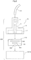
- Fig. 2 there will be explained by way of an example of the connector module 10 contemplated for use in a camera unit 100 (vehicle-mounted camera) to be mounted on a vehicle.
- the camera unit 100 can be used also in any other application than the application of vehicle mounting (e.g. can be mounted also on a bicycle, a drone, etc.).
- the camera unit 100 includes a camera module 110 and the connector module 10.
- the camera module 110 includes, at least, an image pickup device 101, an electronic circuit 102 for driving and controlling the image pickup device 101 and processing video signals outputted from the image pickup device 101, and an optical unit 104 having a lens 103 for condensing light onto the image pickup device 101.
- the camera unit 100 is connected to an image processing device (not shown) or a monitoring device (not shown) via a coaxial cable 120.
- the coaxial cable 120 comprises a cable configured such that an inner conductor and an outer conductor are disposed coaxially across a dielectric (insulator) therebetween.
- the inner conductor transmits signals whereas the outer conductor acts as a shield for suppressing influence of electromagnetic wave to the inner conductor.
- the inner conductor supplies electric power from the image processing device or the monitoring device to the image pickup device 101 or the electronic circuit 102 of the camera unit 100 and also outputs video signals outputted from the image pickup device 101 and the electronic circuit 102 to the image processing device or the monitoring device.
- the camera unit 100 is a photographic device using the known power line carrier system.
- the image pickup device 101 of the camera module 110 comprises a CCD (Charge Coupled Device), a sensor or a CIS (CMOS Image Sensor).
- the lens 103 can be not only a single lens, but also multiple lenses.
- the electronic circuit 102 includes a clock driver for driving the image pickup device 101, and an analog signal processing circuit for effecting analog signal processing such as sample hold, clamp processing, on analog signals outputted from the image pickup device 101.
- the electronic circuit 102 can further include an A/D converter for coverting analog signals to digital signals.
- the electronic circuit 102 can still further include a power circuit for effecting processing such as rectification on a power source supplied via the power line carrier system.
- the electronic circuit 102 is configured as a circuit board in which electronic devices are mounted on a single or multiple printed boards. In the case of providing multiple circuit boards, a flexible board can be used for electric connection between the circuit boards.
- the circuit board on which the electronic circuit 102 is formed mounts also a receptacle (not shown) for connecting the coaxial cable 120.
- the connector module 10 is connected not only to the receptacle, but also to the coaxial cable 120, thus electrically connecting the electronic circuit 102 with the coaxial cable 120.
- the connector module 10 as shown in the exploded perspective view in Fig. 1 , includes a connector case 8, a terminal module 30, a shield case 7, a main body case 9, and an outer seal member 6.
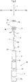
- the terminal module 30, as shown in the exploded perspective view in Fig. 3 includes a center conductor 1, an insulator holder 2, a conductive shell 3, an inner seal member 4 and a retaining ring 5.
- the terminal module 30 has a function which is electrically equivalent to that of the coaxial cable 120. Namely, the center conductor 1 corresponds to an inner conductor of the coaxial cable 120, the insulator holder 2 corresponds to the dielectric (insulator) of the coaxial cable 120, and the conductive shell 3 corresponds to the outer conductor of the coaxial cable 120.
- the terminal module 30 is provided with a characteristic impedance equivalent to that of the coaxial cable 120. More particularly, for the connector module 10 (terminal module 30), there is set a predetermined characteristic impedance (e.g. 50 ⁇ ), based on an outside diameter ( ⁇ 1) of the center conductor 1, an inside diameter ( ⁇ 3) of the conductive shell 3, and a relative dielectric constant of the insulator holder 2.
- the characteristic impedance Zo is defined e.g. by a following expression (1), with the relative dielectric constant of the insulator holder being ( ⁇ ).
- Z 0 60 ⁇ log e ⁇ 3 ⁇ 1
- the connector case 8 is a case for accommodating the terminal module 30 and the shield case 7.
- the connector case 8 is disposed rearwardly of the camera module 110, so this case 8 may sometimes be referred to as "rear case”.
- the shield case 7 covers at least a part of the electronic circuit 102 of the camera module 110, thus shielding the electronic circuit 102 against electromagnetic wave such as electromagnetic noise.
- the shield case 7 can be connected to the ground (GND) of the electronic circuit 102.
- the outer conductor of the coaxial cable 120 is electrically connected to the conductive shell 3. Further, as will be explained later herein, the shield case 7 and the conductive shell 3 are electrically connected to each other. Therefore, in case the shield case 7 is connected to the ground of the electronic circuit 102, the conductive shell 3 and the outer conductor of the coaxial cable 120 are also electrically connected to the ground of the electronic circuit 102.
- the camera unit 100 (vehicle-mounted camera) includes the camera module 110 having the image pickup device 101, the electronic circuit 102 for driving and controlling the image pickup device 101 and processing video signals outputted from the image pickup device 101 and the optical unit 104 having the lens 103 for condensing light onto the image pickup device 101, and the connector module 10. And, to the electronic circuit 102, the center conductor 1 is electrically connected and at least a part of the electronic circuit 102 is shielded by the shield case 7. Next, the connector module 10 will be described in greater details.
- the connector module 10 includes the connector case 8, the terminal module 30, the shield case 7, the main body case 9 and the outer seal member 6.
- the terminal module 30 includes the center conductor 1, the insulator holder 2, the conductive shell 3, the inner seal member 4 and the retaining ring 5.
- the center conductor 1 is a linear-shaped conductor for signal transmission. In the instant embodiment, the center conductor 1 has a form of straight line and the extending direction of the center conductor 1 will be referred to as "a first direction L" hereinafter.
- a direction perpendicular to the first direction L will be referred to as a radial direction R and one direction (side) of the radial direction R extending toward the center conductor 1 will be referred to as a radial inner side R1 and the other direction (side) of the radial direction R extending away from the center conductor 1 will be referred to as a radial outer side R2, respectively.
- the insulator holder 2 comprises a cylindrical member with a thick wall formed of e.g. resin and having a through hole 23 (conductor through hole) for allowing insertion and extension of the center conductor 1 therethrough.
- the length of the insulator holder 2 in the first direction L is shorter than that of the center conductor 1. Therefore, the insulator holder 2 covers a center portion 14 (main line portion) of the center conductor 1 with respect to the first direction L (the extending direction of the center conductor 1) and supports this center conductor 1 (see Fig. 3 and Fig. 4 ). More particularly, the opposed ends (11, 12) of the center conductor 1 are not covered by the insulator holder 2, but exposed to form terminal portions. In the embodiment shown in Fig. 3 and Fig.
- the first terminal portion 11 is disposed on the side of the coaxial cable 120
- the second terminal portion 12 is disposed on the side of the camera module 110 (e.g. the side of the receptacle).
- the outside diameters of the center conductor 1 are set such that the outside diameter of the terminal portions (11, 12) is smaller than the outside diameter of the center portion 14 (the main line portion).
- the outside diameter ( ⁇ 1) of the center conductor 1 for defining the characteristic impedance Zo described above is the outside diameter of the center portion 14.
- the conductive shell 3 comprises a cylindrical member configured to cover the radial outer side R2 of the insulator holder 2.
- the conductive shell 3 is formed of metal.
- An inside diameter ( ⁇ 3) of the conductive shell 3 is one of the parameters for use in defining the characteristic impedance Zo, as described hereinbefore and the inner circumferential face 3a is formed substantially uniform.
- annular extending portion 33 which extends annularly on the radial inner side R1 from the inner circumferential face 3a.
- the shield case 7, in this embodiment, is a rectangular-shaped bottomed tubular case.
- the shield case 7 shields the inner space E2 of the case 7 against electromagnetic wave present in an outer space E1 of the shield case 7, e.g. electromagnetic wave such as electromagnetic noise which may influence signals transmitted by the center conductor 1 or the electronic circuit 102 of the camera module 110.
- the shield case 7 too is formed of a conductive material such as metal.
- the shield case 7 includes a bottom portion 71 extending perpendicular to the first direction L along the extending direction of the center conductor 1 and a side wall portion 72 bent from a circumference of the bottom portion 71 and extending along the first direction L (along the direction in the first direction L opposite the terminal module 30).
- the bottom portion 71 includes an opening portion 73 through which the terminal module 30 (conductive shell 3) extends and a protruding portion 75 bent from an edge of the opening portion 73 (an opening edge portion 73e) and protruding in a cylindrical form along the first direction L (along the extending direction of the side wall portion 72).
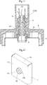
- the shield case 7 and the terminal module 30 (conductive shell 3) are joined to each other (see Fig. 6 and Fig. 7 ).
- the connector case 8 is a case for accommodating the terminal module 30 and the shield case 7.
- the connector case 8 includes, on its inner face side, a cylindrical space E3 for enclosing the terminal module 30, a rectangular-shaped tubular space which is in substantial agreement with the inner space E2 of the shield case 7.
- the terminal module 30 is accommodated in the cylindrical space E3 and the shield case 7 is accommodated in the rectangular-shaped tubular space.
- this space becomes a shielded space (inner space E2) shielded against electromagnetic noise or the like.
- the outer face of the terminal module 30 constitutes the conductive shell 3 and the shield case 7 too has conductivity. Therefore, in order to insulate the conductive shell 3 and the shield case 7 from the outside of the connector module 10, the connector case 8 is formed of an insulating (non-conductive) material such as resin.
- the connector case 8 accommodates the terminal module 30 and the shield case 7 as these terminal module 30 and shield case 7 are joined to each other.
- the terminal module 30 and the shield case 7 are joined to each other in such a manner that an outer circumferential face 3b of the conductive shell 3 and the inner circumferential face 75a of the protruding portion 75 are placed in face contact with each other.
- the conductive shell 3 and the shield case 7 both are formed of conductive material such as metal, with the above-described bonding, the conductive shell 3 and the shield case 7 are connected electrically as well.
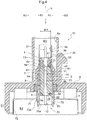
- an end portion of the conductive shell 3 is press-fitted into an accommodating space E4 (see Fig. 4 ) of the protruding portion 75, and an outer circumferential face 3b of the end portion of the conductive shell 3 and the inner circumferential face 75a of the protruding portion 75 are placed in pressure-contact with each other.
- the conductive shell 3 and the shield case 7 are joined to each other, without forming any gap at the edge portion (opening edge portion 73e; see Fig. 7 ) of the opening portion 73 in the bottom portion 71 of the shield case 7.
- This arrangement can appropriately suppress e.g.
- the joining between the conductive shell 3 and the shield case 7 is not limited to the pressure-fitting described above.
- the conductive shell 3 and the shield case 7 can be joined to each other by inserting the conductive shell 3 into the accommodating space E4 of the protruding portion 75 and then welding, adhering, or soldering the opening edge portion 73e.
- the terminal module 30 includes the center conductor 1, the insulator holder 2, the conductive shell 3, the inner seal member 4 and the retaining ring 5.
- the center conductor 1, the insulator holder 2 and the conductive shell 3 together provide the electrically equivalent function of a coaxial cable as described above.
- the inner seal member 4 seals against intrusion of liquid or the like into the terminal module 30 which functions as a coaxial cable.
- the inner seal member 4 comprises a toric shaped member (elastic member) having elasticity. As shown in Fig. 4 , an outer circumferential portion 4b on the radial outer side R2 of the inner seal member 4 is placed in pressure-contact with the inner circumferential face 3a of the conductive shell 3. Also, the inner circumferential portion 4a of the radial inner side R1 of the inner seal member 4 is placed in pressure-contact with the center conductor 1. The inner circumferential portion 4a of the inner seal member 4 is placed in pressure-contact with the center conductor 1 at a bulging portion 13 of the center conductor 1 which portion has a greater outside diameter than the remaining portion thereof. As the inner seal member 4 is an elastic member, this inner seal member 4 is elastically deformed according to the outside diameter of the center conductor 1, thus being placed in pressure-contact with the center conductor 1.
- the conductive shell 3 has the annular extending portion 33 extending annularly from the inner circumferential face 3a.
- the inner seal member 4 is set in the terminal module 30, with one side face (first face 41) thereof with respect to the first direction L being retained by the annular extending portion 33 and the other side face (second face 42) thereof being retained by the end face (first face 21) of the insulator holder 2 with respect to the first direction L.
- the retaining ring 5 cooperates with the annular extending portion 33 to clamp the inner seal member 4 and the insulator holder 2 between the retaining ring 5 and the annular extending portion 33, thus fixing these in position inside the conductive shell 3 with respect to the first direction L.
- the retaining ring 5 is a toric member and defines a through hole at the center portion thereof. The inside diameter ( ⁇ 5) of this through hole is sized to allow at least insertion and extension of the center conductor 1 therethrough.
- a retaining portion 25 that protrudes in the first direction L from the second face 22 of the insulator holder 2 is inserted into the through hole of the retaining ring 5 and an inner circumferential portion 5a of the retaining ring 5 is placed in contact with the insulator holder 2 (retaining portion 25). Therefore, in the instant embodiment, the inside diameter ( ⁇ 5) of the through hole is sized to allow insertion/extension of the retaining portion 25 (for instance, the outside diameter of the retaining portion 25 is equal to or smaller than the inside diameter ( ⁇ 5) of the through hole).
- the outside diameter of the retaining portion 25 can be made greater than the inside diameter ( ⁇ 5) of the through hole. Further, since the center conductor 1 extends through the center of the retaining portion 25, the outside diameter of the retaining portion 25 is greater than the outside diameter ( ⁇ 1) of the center conductor 1.
- the retaining ring 5 is fixed to the conductive shell 3 with the outer circumferential portion 5b on the radial outer side R2 thereof being placed in contact with the inner circumferential face 3a of the conductive shell 3.
- the retaining ring 5 and the conductive shell 3 can be fixed to each other by engaging by press-fitting the retaining ring 5 to the conductive shell 3.
- the conductive shell 3 and the retaining ring 5 can be fixed by welding , adhesion, etc. also.
- the conductive shell 3 has the annular extending portion 33 that extends annularly from the inner circumferential face 3a.
- the terminal module 30 is formed by placing the inner seal member 4 in contact with the annular extending portion 33, placing the insulator holder 2 supporting the center conductor 1 in contact with the inner seal member 4 and placing the retaining ring 5 in contact with the insulator holder 2.
- the inner seal member 4 and the insulator holder 2 are disposed at a predetermined position to each other with respect to the first direction L, as being clamped between the annular extending portion 33 and the retaining ring 5.
- the terminal module 30 formed as described above is then joined to the shield case 7 in the manner described above.
- An intermediate assembled article including the terminal module 30 and the shield case 7 joined to each other will be referred to a 'terminal module assembly' for the sake of convenience of explanation.
- This terminal module assembly is attached to the connector case 8.
- the connector case 8 has, on the inner face side thereof, the cylindrical space E3 which encloses the terminal module 30 and the rectangular-shaped tubular space which is in substantial agreement with the inner space E2 of the shield case 7.
- the terminal module 30 is accommodated in the cylindrical space E3 and the shield case 7 is accommodated in the rectangular-shaped tubular space.
- a seal member (outer seal member 6) is attached in the cylindrical space E3.
- this outer seal member 6 is disposed on the shield case 7 side with respect to the first direction L.
- This outer seal member 6 too is a toric member having elasticity (elastic member).
- An outer circumferential portion 6b on the radial outer side R2 of the outer seal member 6 is placed in pressure-contact with the inner circumferential face 8a of the connector case 8 which face forms the cylindrical space E3. Also, an inner circumferential portion 6a on the radial inner side R1 of the outer seal member 6 is placed in pressure-contact with the outer circumferential face 3b of the conductive shell 3.
- the sealing arrangements using the inner seal member 4 and/or the outer seal member 6 is effective and useful.
- the camera unit 100 as a vehicle-mounted camera is often utilized for driving assistance or recording traveling conditions as well.
- the camera unit 100 will often be mounted to an exterior of the vehicle body, such as a dumper, a door, etc.
- Such exterior of a vehicle body is often exposed to splash of water droplets from rain water, snow or puddles formed in the road, etc. Therefore, preferably, by providing the sealing arrangements described above, the connector module 10 can be provided with water-resistance.
- the inner circumferential face 8a of the connector case 8 forming the cylindrical space E3 includes an engaging pawl 81 that protrudes on radial inner side R1 from the inner circumferential face 8a and provides an elastic force along the radial direction R.
- the outer circumferential face 3b of the conductive shell 3 includes an engaging recessed portion 31 in which the engaging pawl 81 engages.
- the terminal module assembly (terminal module 30) is retained to the connector case 8.
- the respective components (in particular, the conductive shell 3 and the shield case 7) of the terminal module assembly can be formed with such tolerance that allows the bottom portion 71 of the shield case 7 to come into contact with the connector case 8 after establishment of engagement between the engaging pawl 81 and the engaging recessed portion 31.
- the assembled article formed by accommodating the terminal module 30 and the shield case 7 in the connector case 8 and fixed thereto constitutes the connector module 10 in the narrow sense of the language.
- This narrowly defined connector module 10 can be referred to as the connector module 10 with addition of the main body case 9.
- the connector module 10 will be rendered substantially equivalent to the camera unit 100. Therefore, the assembled article having the terminal module 30 and the shield case 7 being accommodated in and fixed to the connector case 8, the intermediate assembled article including the main body case 9, and also the camera unit 100 accommodating the camera module 110 all can be caused to correspond to the connector module 10.
- the article having the terminal module 30 and the shield case 7 being accommodated in and fixed to the connector case 8 will be referred to as the "connector module 10", in the following discussion.
- the connector assembly can be formed by assembling only the terminal module 30 with the connector case 8.
- the connector module 10 can be assembled by joining the conductive shell 3 of the connector case assembly with the shield case 7.
- the connector module 10 can be assembled by assembling only the conductive shell 3 to the connector case 8 and then assembling the inner seal member 4, the insulator holder 2 retaining the center conductor 1 and the retaining ring 5 one after another in this mentioned order to this conductive shell 3 and then joining the shield case 7.
- the center conductor 1 is retained to the insulator holder 2. Instead, after the insulator holder 2 is inserted into the conductive shell 3, the center conductor 1 may be inserted into the through hole 23 of the insulator holder 2.
- the connector module 10 can be assembled with small number of components, and by a small number of steps, without using a washer or the like. Namely, according to the instant embodiment, it is possible to realize the connector module 10 enabling connection between the coaxial cable 120 and the circuit (camera unit 100) and having only small number of components, but providing high shielding performance.
Landscapes
- Engineering & Computer Science (AREA)
- Multimedia (AREA)
- Microelectronics & Electronic Packaging (AREA)
- Signal Processing (AREA)
- Details Of Connecting Devices For Male And Female Coupling (AREA)
- Coupling Device And Connection With Printed Circuit (AREA)
- Mechanical Engineering (AREA)
- Shielding Devices Or Components To Electric Or Magnetic Fields (AREA)
- Camera Bodies And Camera Details Or Accessories (AREA)
- Accessories Of Cameras (AREA)
- Studio Devices (AREA)
- Connector Housings Or Holding Contact Members (AREA)
Claims (7)
- Steckermodul (10), umfassend:ein Anschlussmodul (30), das einen mittleren Leiter (1), eine rohrförmige leitfähige Hülse (3) und eine rohrförmige isolierende Halterung (2); ein Abschirmungsgehäuse (7) und ein nicht leitfähiges Steckergehäuse (8) aufweist;wobei der mittleren Leiter als ein linear geformter mittlerer Leiter (1) zur Signalübertragung ausgebildet ist, dessen eines Ende mit einem Kameramodul elektrisch zu verbinden ist und dessen anderes Ende mit einem Kabel elektrisch zu verbinden ist,wobei die rohrförmige isolierende Halterung (2) ein Durchgangsloch (23) in deren Mitte hat, um ein Durchführen des mittleren Leiters (1) durch sie hindurch zu erlauben, wobei der Halter (2) dazu konfiguriert ist, bezüglich seiner Erstreckungsrichtung einen Mittelteil des mittleren Leiters (1) abzudecken und den mittleren Leiter (1) zu halten, undwobei die rohrförmige leitfähige Hülse (3) dazu konfiguriert ist, eine radial äußere Seite (R2) der isolierenden Halterung (2) abzudecken;wobei das Abschirmungsgehäuse (7) als ein mit einem Boden ausgestattetes rohrförmiges leitfähiges Gehäuse vorgesehen und dazu konfiguriert ist, einen Innenraum des Abschirmungsgehäuses (7) gegen eine in einem äußeren Raum des Abschirmungsgehäuses (7) gegebene Ausbreitung elektromagnetischer Wellen abzuschirmen; unddas nicht leitfähige Steckergehäuse (8) einen zylindrischen Raum (E3) aufweist, der das Anschlussmodul (30) einschließt und in dem das Anschlussmodul (30) und das Abschirmungsgehäuse (7) untergebracht sind;wobei das Abschirmungsgehäuse (7) einen Bodenteil (71), der sich senkrecht zu einer ersten Richtung (L) erstreckt, die entlang der Erstreckungsrichtung des mittleren Leiters (1) ist, und einen Seitenwandteil (72) aufweist, der von einem äußeren Rand des Bodenteils (71) aus gebogen ist und sich entlang der ersten Richtung (L) erstreckt;wobei der Bodenteil (71) einen Öffnungsteil (73) aufweist, durch den sich das Anschlussmodul (30) erstreckt,dadurch gekennzeichnet, dass der Bodenteil (71) ferner einen vorstehenden Teil (75) aufweist, der von einem Rand (73e) des Öffnungsteils (73) aus gebogen ist und in einer zylindrischen Form entlang der ersten Richtung (L) vorsteht;wobei das Anschlussmodul (30) mit dem Abschirmungsgehäuse (7) verbunden ist, wobei eine äußere Mantelfläche (3b) der leitfähigen Hülse (3) und eine innere Mantelfläche (75a) des vorstehenden Teils (75) in flächigem Kontakt aneinander anliegen,wobei eine innere Mantelfläche (8a) des Steckergehäuses (8), die den zylindrischen Raum (E3) bildet, einen Schnapphaken (81) aufweist, der auf einer radial inneren Seite (R1) von der inneren Mantelfläche (8a) vorsteht und eine elastische Kraft entlang einer radialen Richtung (R) bereitstellt;eine äußere Mantelfläche (3b) der leitfähigen Hülse (3) einen vertieften Eingriffsteil (31) aufweist, in den der Schnapphaken (81) eingreift; undein Eingriff zwischen dem Schnapphaken (81) und dem vertieften Eingriffsteil (31) eine Bewegung des Anschlussmoduls (30) entlang der ersten Richtung (L) relativ zu dem Steckergehäuse (8) einschränkt und das Anschlussmodul (30) an dem Steckergehäuse (8) festhält.
- Steckermodul (10) gemäß Anspruch 1, wobei ein Endteil der leitfähigen Hülse (3) in einen Unterbringungsraum (E4), der auf der radial inneren Seite (R1) des vorstehenden Teils (75) ausgebildet ist, eingepresst wird.
- Steckermodul (10) gemäß Anspruch 1 oder 2, wobei:das Anschlussmodul (30) ein inneres Dichtungselement (4) aufweist, das als ein torisches Element ausgebildet ist, das einen äußeren umlaufenden Teil (4a) auf dessen radial äußerer Seite (R2) hat, der in Presskontakt mit einer inneren Mantelfläche (3a) der leitfähigen Hülse (3) gebracht ist, und einen inneren umlaufenden Teil (4a) auf dessen radial innerer Seite (R1) hat, der in Presskontakt mit dem mittleren Leiter (1) gebracht ist, wodurch das Innere des Anschlussmoduls (30) abgedichtet wird;die leitfähige Hülse (3) einen sich ringförmig erstreckenden Teil (33) aufweist, der sich von dessen innerer Mantelfläche (3a) aus ringförmig erstreckt; undvon dem inneren Dichtungselement (4) eine Fläche (41) bezüglich der ersten Richtung (L) durch den sich ringförmig erstreckenden Teil (33) festgehalten wird und die andere Fläche (42) bezüglich der ersten Richtung (L) von einer Stirnfläche (21) der isolierenden Halterung (2) bezüglich der ersten Richtung (L) festgehalten wird, wodurch das innere Dichtungselement (4) in dem Anschlussmodul (30) an Ort und Stelle festgesetzt ist.
- Steckermodul (10) gemäß Anspruch 3, wobei:das Anschlussmodul (30) einen Haltering (5) aufweist, der als ein torisches Element ausgebildet ist, dessen äußerer umlaufender Teil (5b) auf dessen radial äußerer Seite (R2) mit der inneren Mantelfläche (3a) der leitfähigen Hülse (3) und dessen innerem umlaufendem Teil (5a) auf dessen radial innerer Seite (R1), der einen Innendurchmesser hat, der mindestens dazu abgemessen ist, dass sich der mittleren Leiter (1) durch ihn hindurch erstreckt, in anliegenden Kontakt gebracht ist; unddas innere Dichtungselement (4) und die isolierende Halterung (2) an einer vorbestimmten Position zueinander entlang der ersten Richtung (L) angeordnet sind, wobei sie zwischen dem sich ringförmig erstreckenden Teil (33) und dem Haltering (5) gebunden sind.
- Steckermodul (10) gemäß einem der Ansprüche 1 bis 4, wobei:das Steckermodul (10) ein äußeres Dichtungselement (6) aufweist, das als ein torisches Element ausgebildet ist, das den zylindrischen Raum mit einem äußeren umlaufenden Teil (6b) auf dessen radial äußerer Seite (R2) abdichtet, die mit einer inneren Mantelfläche (8a) des Steckergehäuses (8) in Presskontakt gebracht ist, wobei die Fläche den zylindrischen Raum (E3) bildet, und ein innerer umlaufender Teil (6a) auf dessen radial innerer Seite (R1) in Presskontakt mit einer äußeren Mantelfläche (3b) der leitfähigen Hülse (3) gebracht ist; unddas äußere Dichtungselement (6) bezüglich der ersten Richtung (L) auf der Seite des Abschirmungsgehäuses (7) angeordnet ist.
- Steckermodul (10) gemäß einem der Ansprüche 1 bis 5, wobei das Steckermodul (10) eine vorbestimmte charakteristische Impedanz (Zo) hat, die auf Basis eines Außendurchmessers (ϕ1) des mittleren Leiters (1), eines Innendurchmessers (ϕ3) der leitfähigen Hülse (3) und einer relativen dielektrischen Konstante (ε) der isolierenden Halterung (2) eingestellt ist.
- Fahrzeug-Bordkamera (100), umfassend:
ein Kameramodul (110), aufweisend:eine Bildaufnahmevorrichtung (101),eine elektronische Schaltung (102), die dazu konfiguriert ist, die Bildaufnahmevorrichtung (101) zu treiben und zu steuern und auch ein von der Bildaufnahmevorrichtung (101) ausgegebenes Videosignal zu verarbeiten, undeine optische Einheit (104), die eine Linse (103) zum Bündeln von Licht auf die Bildaufnahmevorrichtung (101) hat;das Steckermodul (10) gemäß einem der Ansprüche 1 bis 6;wobei der mittlere Leiter (1) mit der elektronischen Schaltung (102) elektrisch verbunden ist; undmindestens ein Teil der elektronischen Schaltung (102) durch das Abschirmungsgehäuse (7) abgeschirmt ist.
Applications Claiming Priority (1)
| Application Number | Priority Date | Filing Date | Title |
|---|---|---|---|
| JP2016131813A JP6704806B2 (ja) | 2016-07-01 | 2016-07-01 | コネクタモジュール及びそれを用いた車載カメラ |
Publications (2)
| Publication Number | Publication Date |
|---|---|
| EP3264537A1 EP3264537A1 (de) | 2018-01-03 |
| EP3264537B1 true EP3264537B1 (de) | 2021-09-22 |
Family
ID=59009617
Family Applications (1)
| Application Number | Title | Priority Date | Filing Date |
|---|---|---|---|
| EP17174466.7A Active EP3264537B1 (de) | 2016-07-01 | 2017-06-06 | Verbindungsmodul und fahrzeugmontierte kamera mit solch einem modul |
Country Status (4)
| Country | Link |
|---|---|
| US (1) | US10205285B2 (de) |
| EP (1) | EP3264537B1 (de) |
| JP (1) | JP6704806B2 (de) |
| CN (1) | CN107565246B (de) |
Families Citing this family (44)
| Publication number | Priority date | Publication date | Assignee | Title |
|---|---|---|---|---|
| TWI586266B (zh) * | 2016-06-17 | 2017-06-11 | 元智大學 | 水產養殖系統 |
| JP6996838B2 (ja) * | 2016-09-12 | 2022-01-17 | ヒロセ電機株式会社 | コネクタおよびコネクタユニット |
| JP6779123B2 (ja) | 2016-12-27 | 2020-11-04 | ホシデン株式会社 | レセプタクルコネクタおよびコネクタ |
| JP6749232B2 (ja) * | 2016-12-27 | 2020-09-02 | ホシデン株式会社 | レセプタクルコネクタおよびカメラユニット |
| JP2018147844A (ja) * | 2017-03-09 | 2018-09-20 | Smk株式会社 | 電気コネクタの取付構造及び電気コネクタモジュールの製造方法 |
| TWI639047B (zh) * | 2017-10-13 | 2018-10-21 | 致伸科技股份有限公司 | 車用相機模組 |
| CN108540695B (zh) * | 2018-04-02 | 2020-05-15 | 环旭电子股份有限公司 | 车用摄像模块 |
| JP7017987B2 (ja) * | 2018-06-13 | 2022-02-09 | ホシデン株式会社 | コネクタアッセンブリ、接続モジュール及び接続モジュールの製造方法 |
| CN109278644A (zh) * | 2018-07-27 | 2019-01-29 | 惠州市德赛西威汽车电子股份有限公司 | 一种基于高清摄像头的智能电子后视镜及其图像采集方法 |
| JP7150513B2 (ja) * | 2018-08-09 | 2022-10-11 | キヤノン株式会社 | 光学機器、撮像装置 |
| CN109149281A (zh) * | 2018-10-10 | 2019-01-04 | 深圳市朗英科技开发有限公司 | 一种连接器及摄像装置 |
| JP7195865B2 (ja) * | 2018-10-12 | 2022-12-26 | ヒロセ電機株式会社 | 中継コネクタおよびカメラモジュール |
| JP6703313B1 (ja) * | 2018-12-04 | 2020-06-03 | Smk株式会社 | カメラ用コネクタモジュール |
| EP3886272B1 (de) * | 2018-12-19 | 2024-02-28 | Mitsubishi Electric Corporation | Entrauschungsbauteil |
| CN112859490A (zh) | 2019-11-12 | 2021-05-28 | 法雷奥汽车内部控制(深圳)有限公司 | 具有用于屏蔽电磁辐射的壳体的相机及机动车辆 |
| DE102020108771A1 (de) | 2020-03-30 | 2021-09-30 | Connaught Electronics Ltd. | Verfahren zur Montage einer Kamera für ein Fahrzeug, Vormontagemodul für eine Kamera, sowie Kamera |
| JP2021166161A (ja) * | 2020-04-07 | 2021-10-14 | ホシデン株式会社 | コネクタモジュール |
| JP7411505B2 (ja) * | 2020-06-03 | 2024-01-11 | ホシデン株式会社 | シールド部材、シールドユニット、及びコネクタモジュール |
| KR20210158621A (ko) * | 2020-06-24 | 2021-12-31 | 엘지이노텍 주식회사 | 카메라 모듈 |
| JP2022011703A (ja) * | 2020-06-30 | 2022-01-17 | 山一電機株式会社 | ケーブルコネクタ及びモジュールユニット |
| JP7460959B2 (ja) * | 2020-09-14 | 2024-04-03 | 株式会社オートネットワーク技術研究所 | シールドコネクタ |
| JP7454124B2 (ja) * | 2020-09-14 | 2024-03-22 | 株式会社オートネットワーク技術研究所 | シールドコネクタ |
| CN112468702B (zh) * | 2020-11-24 | 2024-10-15 | 苏州祥龙嘉业电子科技股份有限公司 | 一种具有屏蔽性能的车载摄像头外壳体结构 |
| CN114744435B (zh) * | 2021-01-08 | 2024-07-23 | 东莞莫仕连接器有限公司 | 电连接器组合及其制造方法 |
| DE102021103232B3 (de) | 2021-02-11 | 2022-06-02 | Te Connectivity Germany Gmbh | Anschlussvorrichtung für ein elektrisches und/oder elektronisches Gerät mit einem Gerätegehäuse, sowie Gerätegehäuseanordnung und Sensoranordnung |
| JP2024522948A (ja) * | 2021-03-22 | 2024-06-24 | タイコ エレクトロニクス アンプ コリア カンパニー リミテッド | コネクタアセンブリ |
| DE102021107713A1 (de) * | 2021-03-26 | 2022-09-29 | Te Connectivity Germany Gmbh | Elektrisch isolierende berührungsschutzvorrichtung und verbindungsanordnung mit einer solchen berührungsschutzvorrichtung |
| US11870179B2 (en) * | 2021-04-09 | 2024-01-09 | Te Connectivity Solutions Gmbh | Pin assembly having a seal |
| JP2023034101A (ja) | 2021-08-30 | 2023-03-13 | イリソ電子工業株式会社 | 電子部品 |
| CN113783025B (zh) * | 2021-10-09 | 2025-07-25 | 苏州瑞可达连接系统股份有限公司 | 一种车载防水连接器及其组装方法 |
| CN217239921U (zh) * | 2022-01-22 | 2022-08-19 | 富士康(昆山)电脑接插件有限公司 | 连接器组件 |
| JP7805826B2 (ja) * | 2022-03-14 | 2026-01-26 | ホシデン株式会社 | コネクタモジュール |
| TWI835107B (zh) * | 2022-04-01 | 2024-03-11 | 佳必琪國際股份有限公司 | 插座連接器的防水結構 |
| CN119487363A (zh) * | 2022-07-14 | 2025-02-18 | 大陆智行德国有限公司 | 用于生产传感器模块的方法以及传感器模块 |
| CN115388923B (zh) * | 2022-09-19 | 2023-12-19 | 深圳市威纳智能科技有限公司 | 一种抗磁性能好的智能传感器 |
| WO2024106396A1 (ja) * | 2022-11-16 | 2024-05-23 | ホシデン株式会社 | コネクタモジュール |
| JP2024084929A (ja) * | 2022-12-14 | 2024-06-26 | タイコエレクトロニクスジャパン合同会社 | コネクタ |
| JP2024150972A (ja) * | 2023-04-11 | 2024-10-24 | Smk株式会社 | モジュール用コネクタ及びその製造方法 |
| JP7396529B1 (ja) * | 2023-07-19 | 2023-12-12 | Smk株式会社 | 車載カメラ用リアケース及び車載カメラ用ケース |
| JP7442728B1 (ja) * | 2023-12-14 | 2024-03-04 | Smk株式会社 | 電子機器を内装するケースに対する端子モジュールの固定方法及び電子機器を内装するケースに対する端子モジュールの固定構造 |
| JP2025098729A (ja) | 2023-12-20 | 2025-07-02 | パナソニックオートモーティブシステムズ株式会社 | 車載用カメラ |
| CN118281649B (zh) * | 2024-06-04 | 2024-10-08 | 苏州博海创业微系统有限公司 | 一种适用于表贴连接器的电磁屏蔽罩及电磁屏蔽结构 |
| JP7703088B1 (ja) | 2024-07-29 | 2025-07-04 | ホシデン株式会社 | コネクタ |
| CN119676542B (zh) * | 2025-02-18 | 2025-11-25 | 杭州海康威视数字技术股份有限公司 | 摄像机 |
Family Cites Families (14)
| Publication number | Priority date | Publication date | Assignee | Title |
|---|---|---|---|---|
| JP5065992B2 (ja) | 2008-05-22 | 2012-11-07 | 矢崎総業株式会社 | 電子機器モジュール |
| CN101599603A (zh) * | 2008-06-04 | 2009-12-09 | 鸿富锦精密工业(深圳)有限公司 | 线缆连接器及其制造方法 |
| JP5494927B2 (ja) * | 2009-08-03 | 2014-05-21 | 株式会社リコー | カメラユニット及びセンシング装置 |
| US20120244744A1 (en) * | 2011-03-21 | 2012-09-27 | Ching-Kun Huang | Structure of connector |
| CN202183491U (zh) * | 2011-08-01 | 2012-04-04 | 摩比天线技术(深圳)有限公司 | 射频同轴连接器 |
| JP6039514B2 (ja) * | 2013-07-29 | 2016-12-07 | 日本航空電子工業株式会社 | 電子機器モジュール |
| US9985363B2 (en) * | 2013-10-18 | 2018-05-29 | Venti Group, LLC | Electrical connectors with low passive intermodulation |
| US10298823B2 (en) * | 2014-02-03 | 2019-05-21 | Magna Electronics Inc. | Vehicle camera housing with tolerance compensating connector |
| JP6278782B2 (ja) * | 2014-03-28 | 2018-02-14 | 矢崎総業株式会社 | 同軸コネクタ及びそれを備えたカメラモジュール |
| JP2015210292A (ja) * | 2014-04-24 | 2015-11-24 | Smk株式会社 | 撮像装置 |
| JP2015216444A (ja) * | 2014-05-08 | 2015-12-03 | Smk株式会社 | 撮像装置 |
| DE102014012910A1 (de) * | 2014-09-05 | 2016-03-10 | Kathrein-Werke Kg | Hochfrequenz-Steckverbindungseinrichtung, insbesondere Koaxial-Steckverbindungseinrichtung für Antennensteckdosen |
| DE102014117648A1 (de) | 2014-12-02 | 2016-06-02 | Connaught Electronics Ltd. | Kamera für ein Kraftfahrzeug und Kraftfahrzeug |
| DE102016103965A1 (de) * | 2016-03-04 | 2017-09-07 | Connaught Electronics Ltd. | Kamera mit einem Gehäuse, einer Leiterplatte und einem haubenartigen, federnden Halteelement, Kraftfahrzeug und Verfahren zur Montage einer Kamera |
-
2016
- 2016-07-01 JP JP2016131813A patent/JP6704806B2/ja active Active
-
2017
- 2017-06-06 EP EP17174466.7A patent/EP3264537B1/de active Active
- 2017-06-27 US US15/634,446 patent/US10205285B2/en active Active
- 2017-06-30 CN CN201710523434.3A patent/CN107565246B/zh active Active
Also Published As
| Publication number | Publication date |
|---|---|
| JP6704806B2 (ja) | 2020-06-03 |
| CN107565246B (zh) | 2021-02-12 |
| US10205285B2 (en) | 2019-02-12 |
| JP2018006162A (ja) | 2018-01-11 |
| EP3264537A1 (de) | 2018-01-03 |
| CN107565246A (zh) | 2018-01-09 |
| US20180006407A1 (en) | 2018-01-04 |
Similar Documents
| Publication | Publication Date | Title |
|---|---|---|
| EP3264537B1 (de) | Verbindungsmodul und fahrzeugmontierte kamera mit solch einem modul | |
| EP3462550B1 (de) | Verbindermodul und bordkamera damit | |
| US11515673B2 (en) | Electrical connector module with shielding members engaging upon connection to a mating connector | |
| JP6936710B2 (ja) | コネクタモジュール及びそれを用いた車載カメラ | |
| EP3343705B1 (de) | Buchsenstecker und kameraeinheit | |
| US11967791B2 (en) | Coaxial connector | |
| CN108258496B (zh) | 插座连接器及连接器 | |
| US20210384680A1 (en) | Shield member, shield unit, and connector module | |
| CN105100561A (zh) | 摄像装置 | |
| US20180006390A1 (en) | Electrical Connector, Electronic Component, and Assembly Method | |
| KR20180103656A (ko) | 전기 커넥터의 부착구조 및 전기 커넥터 모듈의 제조방법 | |
| EP4622020A1 (de) | Verbindermodul | |
| US7347730B2 (en) | Grommet | |
| KR100780727B1 (ko) | 차폐 전선과 차폐쉘의 접속 장치 | |
| WO2021181757A1 (ja) | 圧力検出装置、回路内蔵部材 | |
| KR20210040782A (ko) | 커넥터 및 전자 디바이스 | |
| JP2026034947A (ja) | 電気コネクタ |
Legal Events
| Date | Code | Title | Description |
|---|---|---|---|
| PUAI | Public reference made under article 153(3) epc to a published international application that has entered the european phase |
Free format text: ORIGINAL CODE: 0009012 |
|
| STAA | Information on the status of an ep patent application or granted ep patent |
Free format text: STATUS: THE APPLICATION HAS BEEN PUBLISHED |
|
| AK | Designated contracting states |
Kind code of ref document: A1 Designated state(s): AL AT BE BG CH CY CZ DE DK EE ES FI FR GB GR HR HU IE IS IT LI LT LU LV MC MK MT NL NO PL PT RO RS SE SI SK SM TR |
|
| AX | Request for extension of the european patent |
Extension state: BA ME |
|
| STAA | Information on the status of an ep patent application or granted ep patent |
Free format text: STATUS: REQUEST FOR EXAMINATION WAS MADE |
|
| 17P | Request for examination filed |
Effective date: 20180620 |
|
| RBV | Designated contracting states (corrected) |
Designated state(s): AL AT BE BG CH CY CZ DE DK EE ES FI FR GB GR HR HU IE IS IT LI LT LU LV MC MK MT NL NO PL PT RO RS SE SI SK SM TR |
|
| STAA | Information on the status of an ep patent application or granted ep patent |
Free format text: STATUS: EXAMINATION IS IN PROGRESS |
|
| 17Q | First examination report despatched |
Effective date: 20200127 |
|
| REG | Reference to a national code |
Ref country code: DE Ref legal event code: R079 Ref document number: 602017046286 Country of ref document: DE Free format text: PREVIOUS MAIN CLASS: H01R0013659600 Ipc: H01R0024520000 |
|
| GRAP | Despatch of communication of intention to grant a patent |
Free format text: ORIGINAL CODE: EPIDOSNIGR1 |
|
| STAA | Information on the status of an ep patent application or granted ep patent |
Free format text: STATUS: GRANT OF PATENT IS INTENDED |
|
| RIC1 | Information provided on ipc code assigned before grant |
Ipc: H01R 13/52 20060101ALN20210423BHEP Ipc: H01R 13/74 20060101ALI20210423BHEP Ipc: H01R 13/6596 20110101ALI20210423BHEP Ipc: H01R 24/52 20110101AFI20210423BHEP |
|
| INTG | Intention to grant announced |
Effective date: 20210527 |
|
| GRAS | Grant fee paid |
Free format text: ORIGINAL CODE: EPIDOSNIGR3 |
|
| GRAA | (expected) grant |
Free format text: ORIGINAL CODE: 0009210 |
|
| STAA | Information on the status of an ep patent application or granted ep patent |
Free format text: STATUS: THE PATENT HAS BEEN GRANTED |
|
| AK | Designated contracting states |
Kind code of ref document: B1 Designated state(s): AL AT BE BG CH CY CZ DE DK EE ES FI FR GB GR HR HU IE IS IT LI LT LU LV MC MK MT NL NO PL PT RO RS SE SI SK SM TR |
|
| REG | Reference to a national code |
Ref country code: GB Ref legal event code: FG4D |
|
| REG | Reference to a national code |
Ref country code: IE Ref legal event code: FG4D |
|
| REG | Reference to a national code |
Ref country code: DE Ref legal event code: R096 Ref document number: 602017046286 Country of ref document: DE |
|
| REG | Reference to a national code |
Ref country code: CH Ref legal event code: EP Ref country code: AT Ref legal event code: REF Ref document number: 1433040 Country of ref document: AT Kind code of ref document: T Effective date: 20211015 |
|
| REG | Reference to a national code |
Ref country code: LT Ref legal event code: MG9D |
|
| REG | Reference to a national code |
Ref country code: NL Ref legal event code: MP Effective date: 20210922 |
|
| PG25 | Lapsed in a contracting state [announced via postgrant information from national office to epo] |
Ref country code: SE Free format text: LAPSE BECAUSE OF FAILURE TO SUBMIT A TRANSLATION OF THE DESCRIPTION OR TO PAY THE FEE WITHIN THE PRESCRIBED TIME-LIMIT Effective date: 20210922 Ref country code: RS Free format text: LAPSE BECAUSE OF FAILURE TO SUBMIT A TRANSLATION OF THE DESCRIPTION OR TO PAY THE FEE WITHIN THE PRESCRIBED TIME-LIMIT Effective date: 20210922 Ref country code: FI Free format text: LAPSE BECAUSE OF FAILURE TO SUBMIT A TRANSLATION OF THE DESCRIPTION OR TO PAY THE FEE WITHIN THE PRESCRIBED TIME-LIMIT Effective date: 20210922 Ref country code: HR Free format text: LAPSE BECAUSE OF FAILURE TO SUBMIT A TRANSLATION OF THE DESCRIPTION OR TO PAY THE FEE WITHIN THE PRESCRIBED TIME-LIMIT Effective date: 20210922 Ref country code: NO Free format text: LAPSE BECAUSE OF FAILURE TO SUBMIT A TRANSLATION OF THE DESCRIPTION OR TO PAY THE FEE WITHIN THE PRESCRIBED TIME-LIMIT Effective date: 20211222 Ref country code: BG Free format text: LAPSE BECAUSE OF FAILURE TO SUBMIT A TRANSLATION OF THE DESCRIPTION OR TO PAY THE FEE WITHIN THE PRESCRIBED TIME-LIMIT Effective date: 20211222 Ref country code: LT Free format text: LAPSE BECAUSE OF FAILURE TO SUBMIT A TRANSLATION OF THE DESCRIPTION OR TO PAY THE FEE WITHIN THE PRESCRIBED TIME-LIMIT Effective date: 20210922 |
|
| REG | Reference to a national code |
Ref country code: AT Ref legal event code: MK05 Ref document number: 1433040 Country of ref document: AT Kind code of ref document: T Effective date: 20210922 |
|
| PG25 | Lapsed in a contracting state [announced via postgrant information from national office to epo] |
Ref country code: LV Free format text: LAPSE BECAUSE OF FAILURE TO SUBMIT A TRANSLATION OF THE DESCRIPTION OR TO PAY THE FEE WITHIN THE PRESCRIBED TIME-LIMIT Effective date: 20210922 Ref country code: GR Free format text: LAPSE BECAUSE OF FAILURE TO SUBMIT A TRANSLATION OF THE DESCRIPTION OR TO PAY THE FEE WITHIN THE PRESCRIBED TIME-LIMIT Effective date: 20211223 |
|
| PG25 | Lapsed in a contracting state [announced via postgrant information from national office to epo] |
Ref country code: AT Free format text: LAPSE BECAUSE OF FAILURE TO SUBMIT A TRANSLATION OF THE DESCRIPTION OR TO PAY THE FEE WITHIN THE PRESCRIBED TIME-LIMIT Effective date: 20210922 |
|
| PG25 | Lapsed in a contracting state [announced via postgrant information from national office to epo] |
Ref country code: IS Free format text: LAPSE BECAUSE OF FAILURE TO SUBMIT A TRANSLATION OF THE DESCRIPTION OR TO PAY THE FEE WITHIN THE PRESCRIBED TIME-LIMIT Effective date: 20220122 Ref country code: SK Free format text: LAPSE BECAUSE OF FAILURE TO SUBMIT A TRANSLATION OF THE DESCRIPTION OR TO PAY THE FEE WITHIN THE PRESCRIBED TIME-LIMIT Effective date: 20210922 Ref country code: RO Free format text: LAPSE BECAUSE OF FAILURE TO SUBMIT A TRANSLATION OF THE DESCRIPTION OR TO PAY THE FEE WITHIN THE PRESCRIBED TIME-LIMIT Effective date: 20210922 Ref country code: PT Free format text: LAPSE BECAUSE OF FAILURE TO SUBMIT A TRANSLATION OF THE DESCRIPTION OR TO PAY THE FEE WITHIN THE PRESCRIBED TIME-LIMIT Effective date: 20220124 Ref country code: PL Free format text: LAPSE BECAUSE OF FAILURE TO SUBMIT A TRANSLATION OF THE DESCRIPTION OR TO PAY THE FEE WITHIN THE PRESCRIBED TIME-LIMIT Effective date: 20210922 Ref country code: NL Free format text: LAPSE BECAUSE OF FAILURE TO SUBMIT A TRANSLATION OF THE DESCRIPTION OR TO PAY THE FEE WITHIN THE PRESCRIBED TIME-LIMIT Effective date: 20210922 Ref country code: ES Free format text: LAPSE BECAUSE OF FAILURE TO SUBMIT A TRANSLATION OF THE DESCRIPTION OR TO PAY THE FEE WITHIN THE PRESCRIBED TIME-LIMIT Effective date: 20210922 Ref country code: EE Free format text: LAPSE BECAUSE OF FAILURE TO SUBMIT A TRANSLATION OF THE DESCRIPTION OR TO PAY THE FEE WITHIN THE PRESCRIBED TIME-LIMIT Effective date: 20210922 Ref country code: CZ Free format text: LAPSE BECAUSE OF FAILURE TO SUBMIT A TRANSLATION OF THE DESCRIPTION OR TO PAY THE FEE WITHIN THE PRESCRIBED TIME-LIMIT Effective date: 20210922 Ref country code: AL Free format text: LAPSE BECAUSE OF FAILURE TO SUBMIT A TRANSLATION OF THE DESCRIPTION OR TO PAY THE FEE WITHIN THE PRESCRIBED TIME-LIMIT Effective date: 20210922 |
|
| REG | Reference to a national code |
Ref country code: DE Ref legal event code: R097 Ref document number: 602017046286 Country of ref document: DE |
|
| PG25 | Lapsed in a contracting state [announced via postgrant information from national office to epo] |
Ref country code: DK Free format text: LAPSE BECAUSE OF FAILURE TO SUBMIT A TRANSLATION OF THE DESCRIPTION OR TO PAY THE FEE WITHIN THE PRESCRIBED TIME-LIMIT Effective date: 20210922 |
|
| PLBE | No opposition filed within time limit |
Free format text: ORIGINAL CODE: 0009261 |
|
| STAA | Information on the status of an ep patent application or granted ep patent |
Free format text: STATUS: NO OPPOSITION FILED WITHIN TIME LIMIT |
|
| 26N | No opposition filed |
Effective date: 20220623 |
|
| PG25 | Lapsed in a contracting state [announced via postgrant information from national office to epo] |
Ref country code: SI Free format text: LAPSE BECAUSE OF FAILURE TO SUBMIT A TRANSLATION OF THE DESCRIPTION OR TO PAY THE FEE WITHIN THE PRESCRIBED TIME-LIMIT Effective date: 20210922 |
|
| PG25 | Lapsed in a contracting state [announced via postgrant information from national office to epo] |
Ref country code: MC Free format text: LAPSE BECAUSE OF FAILURE TO SUBMIT A TRANSLATION OF THE DESCRIPTION OR TO PAY THE FEE WITHIN THE PRESCRIBED TIME-LIMIT Effective date: 20210922 Ref country code: IT Free format text: LAPSE BECAUSE OF FAILURE TO SUBMIT A TRANSLATION OF THE DESCRIPTION OR TO PAY THE FEE WITHIN THE PRESCRIBED TIME-LIMIT Effective date: 20210922 |
|
| REG | Reference to a national code |
Ref country code: CH Ref legal event code: PL |
|
| REG | Reference to a national code |
Ref country code: BE Ref legal event code: MM Effective date: 20220630 |
|
| PG25 | Lapsed in a contracting state [announced via postgrant information from national office to epo] |
Ref country code: LU Free format text: LAPSE BECAUSE OF NON-PAYMENT OF DUE FEES Effective date: 20220606 Ref country code: LI Free format text: LAPSE BECAUSE OF NON-PAYMENT OF DUE FEES Effective date: 20220630 Ref country code: IE Free format text: LAPSE BECAUSE OF NON-PAYMENT OF DUE FEES Effective date: 20220606 Ref country code: CH Free format text: LAPSE BECAUSE OF NON-PAYMENT OF DUE FEES Effective date: 20220630 |
|
| PG25 | Lapsed in a contracting state [announced via postgrant information from national office to epo] |
Ref country code: BE Free format text: LAPSE BECAUSE OF NON-PAYMENT OF DUE FEES Effective date: 20220630 |
|
| PG25 | Lapsed in a contracting state [announced via postgrant information from national office to epo] |
Ref country code: HU Free format text: LAPSE BECAUSE OF FAILURE TO SUBMIT A TRANSLATION OF THE DESCRIPTION OR TO PAY THE FEE WITHIN THE PRESCRIBED TIME-LIMIT; INVALID AB INITIO Effective date: 20170606 |
|
| PG25 | Lapsed in a contracting state [announced via postgrant information from national office to epo] |
Ref country code: SM Free format text: LAPSE BECAUSE OF FAILURE TO SUBMIT A TRANSLATION OF THE DESCRIPTION OR TO PAY THE FEE WITHIN THE PRESCRIBED TIME-LIMIT Effective date: 20210922 Ref country code: MK Free format text: LAPSE BECAUSE OF FAILURE TO SUBMIT A TRANSLATION OF THE DESCRIPTION OR TO PAY THE FEE WITHIN THE PRESCRIBED TIME-LIMIT Effective date: 20210922 Ref country code: CY Free format text: LAPSE BECAUSE OF FAILURE TO SUBMIT A TRANSLATION OF THE DESCRIPTION OR TO PAY THE FEE WITHIN THE PRESCRIBED TIME-LIMIT Effective date: 20210922 |
|
| PG25 | Lapsed in a contracting state [announced via postgrant information from national office to epo] |
Ref country code: TR Free format text: LAPSE BECAUSE OF FAILURE TO SUBMIT A TRANSLATION OF THE DESCRIPTION OR TO PAY THE FEE WITHIN THE PRESCRIBED TIME-LIMIT Effective date: 20210922 |
|
| PG25 | Lapsed in a contracting state [announced via postgrant information from national office to epo] |
Ref country code: MT Free format text: LAPSE BECAUSE OF FAILURE TO SUBMIT A TRANSLATION OF THE DESCRIPTION OR TO PAY THE FEE WITHIN THE PRESCRIBED TIME-LIMIT Effective date: 20210922 |
|
| PGFP | Annual fee paid to national office [announced via postgrant information from national office to epo] |
Ref country code: DE Payment date: 20250509 Year of fee payment: 9 |
|
| PGFP | Annual fee paid to national office [announced via postgrant information from national office to epo] |
Ref country code: GB Payment date: 20250620 Year of fee payment: 9 |
|
| PGFP | Annual fee paid to national office [announced via postgrant information from national office to epo] |
Ref country code: FR Payment date: 20250626 Year of fee payment: 9 |