EP3260289B2 - Verbundelement - Google Patents
Verbundelement Download PDFInfo
- Publication number
- EP3260289B2 EP3260289B2 EP17174921.1A EP17174921A EP3260289B2 EP 3260289 B2 EP3260289 B2 EP 3260289B2 EP 17174921 A EP17174921 A EP 17174921A EP 3260289 B2 EP3260289 B2 EP 3260289B2
- Authority
- EP
- European Patent Office
- Prior art keywords
- insert
- composite element
- hollow profile
- layer
- recovery
- Prior art date
- Legal status (The legal status is an assumption and is not a legal conclusion. Google has not performed a legal analysis and makes no representation as to the accuracy of the status listed.)
- Active
Links
Images
Classifications
-
- B—PERFORMING OPERATIONS; TRANSPORTING
- B32—LAYERED PRODUCTS
- B32B—LAYERED PRODUCTS, i.e. PRODUCTS BUILT-UP OF STRATA OF FLAT OR NON-FLAT, e.g. CELLULAR OR HONEYCOMB, FORM
- B32B7/00—Layered products characterised by the relation between layers; Layered products characterised by the relative orientation of features between layers, or by the relative values of a measurable parameter between layers, i.e. products comprising layers having different physical, chemical or physicochemical properties; Layered products characterised by the interconnection of layers
- B32B7/02—Physical, chemical or physicochemical properties
- B32B7/022—Mechanical properties
-
- B—PERFORMING OPERATIONS; TRANSPORTING
- B32—LAYERED PRODUCTS
- B32B—LAYERED PRODUCTS, i.e. PRODUCTS BUILT-UP OF STRATA OF FLAT OR NON-FLAT, e.g. CELLULAR OR HONEYCOMB, FORM
- B32B15/00—Layered products comprising a layer of metal
- B32B15/04—Layered products comprising a layer of metal comprising metal as the main or only constituent of a layer, which is next to another layer of the same or of a different material
- B32B15/046—Layered products comprising a layer of metal comprising metal as the main or only constituent of a layer, which is next to another layer of the same or of a different material of foam
-
- B—PERFORMING OPERATIONS; TRANSPORTING
- B32—LAYERED PRODUCTS
- B32B—LAYERED PRODUCTS, i.e. PRODUCTS BUILT-UP OF STRATA OF FLAT OR NON-FLAT, e.g. CELLULAR OR HONEYCOMB, FORM
- B32B1/00—Layered products having a non-planar shape
-
- B—PERFORMING OPERATIONS; TRANSPORTING
- B32—LAYERED PRODUCTS
- B32B—LAYERED PRODUCTS, i.e. PRODUCTS BUILT-UP OF STRATA OF FLAT OR NON-FLAT, e.g. CELLULAR OR HONEYCOMB, FORM
- B32B15/00—Layered products comprising a layer of metal
- B32B15/20—Layered products comprising a layer of metal comprising aluminium or copper
-
- B—PERFORMING OPERATIONS; TRANSPORTING
- B32—LAYERED PRODUCTS
- B32B—LAYERED PRODUCTS, i.e. PRODUCTS BUILT-UP OF STRATA OF FLAT OR NON-FLAT, e.g. CELLULAR OR HONEYCOMB, FORM
- B32B5/00—Layered products characterised by the non- homogeneity or physical structure, i.e. comprising a fibrous, filamentary, particulate or foam layer; Layered products characterised by having a layer differing constitutionally or physically in different parts
- B32B5/18—Layered products characterised by the non- homogeneity or physical structure, i.e. comprising a fibrous, filamentary, particulate or foam layer; Layered products characterised by having a layer differing constitutionally or physically in different parts characterised by features of a layer of foamed material
-
- B—PERFORMING OPERATIONS; TRANSPORTING
- B32—LAYERED PRODUCTS
- B32B—LAYERED PRODUCTS, i.e. PRODUCTS BUILT-UP OF STRATA OF FLAT OR NON-FLAT, e.g. CELLULAR OR HONEYCOMB, FORM
- B32B5/00—Layered products characterised by the non- homogeneity or physical structure, i.e. comprising a fibrous, filamentary, particulate or foam layer; Layered products characterised by having a layer differing constitutionally or physically in different parts
- B32B5/22—Layered products characterised by the non- homogeneity or physical structure, i.e. comprising a fibrous, filamentary, particulate or foam layer; Layered products characterised by having a layer differing constitutionally or physically in different parts characterised by the presence of two or more layers which are next to each other and are fibrous, filamentary, formed of particles or foamed
- B32B5/32—Layered products characterised by the non- homogeneity or physical structure, i.e. comprising a fibrous, filamentary, particulate or foam layer; Layered products characterised by having a layer differing constitutionally or physically in different parts characterised by the presence of two or more layers which are next to each other and are fibrous, filamentary, formed of particles or foamed at least two layers being foamed and next to each other
-
- E—FIXED CONSTRUCTIONS
- E04—BUILDING
- E04B—GENERAL BUILDING CONSTRUCTIONS; WALLS, e.g. PARTITIONS; ROOFS; FLOORS; CEILINGS; INSULATION OR OTHER PROTECTION OF BUILDINGS
- E04B5/00—Floors; Floor construction with regard to insulation; Connections specially adapted therefor
- E04B5/02—Load-carrying floor structures formed substantially of prefabricated units
-
- B—PERFORMING OPERATIONS; TRANSPORTING
- B32—LAYERED PRODUCTS
- B32B—LAYERED PRODUCTS, i.e. PRODUCTS BUILT-UP OF STRATA OF FLAT OR NON-FLAT, e.g. CELLULAR OR HONEYCOMB, FORM
- B32B2260/00—Layered product comprising an impregnated, embedded, or bonded layer wherein the layer comprises an impregnation, embedding, or binder material
- B32B2260/02—Composition of the impregnated, bonded or embedded layer
- B32B2260/021—Fibrous or filamentary layer
- B32B2260/023—Two or more layers
-
- B—PERFORMING OPERATIONS; TRANSPORTING
- B32—LAYERED PRODUCTS
- B32B—LAYERED PRODUCTS, i.e. PRODUCTS BUILT-UP OF STRATA OF FLAT OR NON-FLAT, e.g. CELLULAR OR HONEYCOMB, FORM
- B32B2260/00—Layered product comprising an impregnated, embedded, or bonded layer wherein the layer comprises an impregnation, embedding, or binder material
- B32B2260/04—Impregnation, embedding, or binder material
- B32B2260/044—Water-setting substance, e.g. concrete, plaster
-
- B—PERFORMING OPERATIONS; TRANSPORTING
- B32—LAYERED PRODUCTS
- B32B—LAYERED PRODUCTS, i.e. PRODUCTS BUILT-UP OF STRATA OF FLAT OR NON-FLAT, e.g. CELLULAR OR HONEYCOMB, FORM
- B32B2260/00—Layered product comprising an impregnated, embedded, or bonded layer wherein the layer comprises an impregnation, embedding, or binder material
- B32B2260/04—Impregnation, embedding, or binder material
- B32B2260/046—Synthetic resin
-
- B—PERFORMING OPERATIONS; TRANSPORTING
- B32—LAYERED PRODUCTS
- B32B—LAYERED PRODUCTS, i.e. PRODUCTS BUILT-UP OF STRATA OF FLAT OR NON-FLAT, e.g. CELLULAR OR HONEYCOMB, FORM
- B32B2260/00—Layered product comprising an impregnated, embedded, or bonded layer wherein the layer comprises an impregnation, embedding, or binder material
- B32B2260/04—Impregnation, embedding, or binder material
- B32B2260/048—Natural or synthetic rubber
-
- B—PERFORMING OPERATIONS; TRANSPORTING
- B32—LAYERED PRODUCTS
- B32B—LAYERED PRODUCTS, i.e. PRODUCTS BUILT-UP OF STRATA OF FLAT OR NON-FLAT, e.g. CELLULAR OR HONEYCOMB, FORM
- B32B2307/00—Properties of the layers or laminate
- B32B2307/10—Properties of the layers or laminate having particular acoustical properties
- B32B2307/102—Insulating
-
- B—PERFORMING OPERATIONS; TRANSPORTING
- B32—LAYERED PRODUCTS
- B32B—LAYERED PRODUCTS, i.e. PRODUCTS BUILT-UP OF STRATA OF FLAT OR NON-FLAT, e.g. CELLULAR OR HONEYCOMB, FORM
- B32B2307/00—Properties of the layers or laminate
- B32B2307/50—Properties of the layers or laminate having particular mechanical properties
- B32B2307/56—Damping, energy absorption
-
- B—PERFORMING OPERATIONS; TRANSPORTING
- B32—LAYERED PRODUCTS
- B32B—LAYERED PRODUCTS, i.e. PRODUCTS BUILT-UP OF STRATA OF FLAT OR NON-FLAT, e.g. CELLULAR OR HONEYCOMB, FORM
- B32B2419/00—Buildings or parts thereof
- B32B2419/04—Tiles for floors or walls
Definitions
- the present invention relates to a composite element, in particular for floors and walls, the use of an insert in a hollow profile, in particular for floors and walls, for absorbing structure-borne noise and a method for producing a composite element, in particular for floors and walls.
- EP 1 061 100 A1 discloses a sandwich element which is designed to be multi-layered, sound-insulating and mechanically resilient.
- a plastic core is covered with two cover layers, creating a gap or a multitude of gaps between the plastic core and the layers, creating a sound-absorbing effect.
- the plastic core layer is made of a porous material that has at least 50% open cells.
- the DE 195 04 601 A1 relates to a thermally insulated composite profile for a facade construction, which consists of two metal profiles arranged at a distance from one another and between which a thermal insulation material is arranged.
- the DE 199 01 086 A1 relates to a sound-insulating arrangement for a building ceiling, which has an insulating layer lying on the raw ceiling.
- a composite element in particular for floors and walls, comprising a hollow profile which has an at least predominantly closed cavity, an insert which is arranged or can be arranged in the cavity in such a way that the insert is supported on at least two opposite walls of the hollow profile , wherein the insert is formed from an open-pored material which has a delayed recovery after deformation.
- the hollow profile is expediently designed as an element which has a cross-sectional geometry that is essentially constant in a profile direction. In a cross section perpendicular to the profile direction, the hollow profile is expediently designed in such a way that it has an at least predominantly closed cavity.
- the hollow profile encloses a cavity around at least 50% of the circumference, preferably around at least 80% of the cavity.
- the hollow profile can have the shape of a “U” in cross section.
- the hollow profile is designed in such a way that it completely surrounds a cavity in cross section.
- the hollow profile can have a cavity, in which case the hollow profile can also be designed in such a way that it has a multiplicity of cavities, in particular arranged in parallel or along a straight line. These can be designed differently in terms of their geometric design, but in a particularly preferred embodiment they are all designed as a closed cavity.
- the cavity may have any shape, but in a preferred embodiment it is substantially rectangular.
- the cavity has two opposing walls.
- the opposing walls can be designed to be inclined to one another, but in a preferred variant are aligned essentially parallel to one another. It is particularly expedient if one of the opposite walls is that wall which, when the composite element is in use, represents the wall subjected to external influences (foot traffic, rain or hail).
- an insert is provided which is arranged or can be arranged in the cavity.
- the insert is designed in terms of material and/or geometry in such a way that it can be supported on the two opposite walls of the hollow profile. The insert is then supported on the two opposite walls of the hollow profile when it exerts an outwardly directed force on the opposite walls.
- the insert is designed in such a way that, as in the prior art in the hollow profile is formed or manufactured, but the production of the insert ex situ, ie takes place outside of the cavity. It is particularly advantageous that the hollow profile and the insert are two elements that are produced separately from one another and are expediently connected to one another in a further production step after they have been produced. In particular, the insert is elastic.
- the insert is made from an open-pored material which has a delayed recovery after deformation.
- the term “delayed resetting” is understood to mean a setting up or resetting in the direction of setting up the pressed insoles.
- the insole In an unloaded state, the insole is preferably at rest, which means that the insole is not recovering or has completely recovered.
- the insert In the unloaded state, the insert reaches its maximum installation height.
- the liner can be brought into a loaded/depressed state with a reduced installation height by an indentation force.
- the pressing force extends over parts or the entire surface of the insert and is arranged orthogonally to the opposite walls. The impact of the pressing force on the insert reduces the installation height, which is described by the ratio of the pressed installation height to the maximum installation height.
- the installation height is reduced by 30% due to the impact of the crushing force, which means for the delayed reset that the resulting reset distance is 30% of the maximum installation height and the reset distance describes the difference in installation height between the loaded/pressed state and the unloaded state .
- the delayed recovery of the liner begins. From the loaded/depressed state, the liner returns to the unloaded state, or preferably another state, an intermediate state describing partial recovery.
- the duration of the delayed recovery is longer than the recovery exhibited by an insert without impregnation with a binder and/or a filler.
- the delayed reset is preferably 10% of the maximum installation altitude per hour to 6000% of the maximum installation altitude per hour at an ambient air humidity of 40-60% and an ambient temperature of approx. 20° Celsius.
- the advantage of this embodiment is that the delayed recovery can be individually adapted to the application via the impregnation. For example, rapid recovery is preferred when merely inserting the liner into a cavity.
- the delayed reset is preferably between 300% and 6000%, preferably between 500% and 5000%, particularly preferably between 1000% and 3000% of the maximum installation altitude per hour at an ambient humidity of 40-60% and an ambient temperature of approx. 20° Celsius .
- a very slow restoring effect is advantageous since there must be sufficient time for the assembly of the electronic components.
- the delayed recovery is between 10% and 300%, preferably between 50% and 250%, particularly preferably between 100% and 175% of the maximum installation altitude per hour at an ambient humidity of 40-60% and an ambient temperature of about 20° Celsius.
- the delayed resetting can expediently be described linearly, so that the resetting time increases constantly with increasing pressure.
- the delayed return is to be described by an exponential function, with the return time increasing as the impression increases.
- the delayed reset is a combination of a linear and an exponential function, with a linear reset first followed by an exponentially delayed reset.
- the liner is depressed 33% of its maximum deployment height.
- the reset begins immediately, but after three minutes at the latest, preferably one minute, and preferably ends after less than 24 hours.
- the liner is depressed by 35% of its maximum deployment height.
- the delayed recovery occurs in two sections, with the insole returning 10-40% of the recovery path in the first section of the delayed recovery and 90-60% of the recovery path in the second section.
- the delayed recovery is preferably between 300% and 6000%, preferably between 500% and 5000%, particularly preferably between 1000% and 3000% of the maximum installation altitude per hour at an ambient humidity of 40-60% and an ambient temperature of about 20 ° centigrade.
- the delayed recovery is preferably between 300% and 6000%, preferably between 500% and 5000%, particularly preferably between 1000% and 3000% of the maximum installation altitude per hour at an ambient humidity of 40-60% and an ambient temperature of about 20 ° centigrade.
- the insert is particularly advantageously possible, after the insert has been produced, to compress it and insert it into the cavity of the hollow profile in the compressed state. Since the extent of the insert in the compressed state in the vertical direction is less than the distance between the two opposite walls of the hollow profile, the insert can be inserted into the cavity particularly easily.
- the height direction is essentially perpendicular to a width direction, which in turn is perpendicular to the profile direction.
- the opposite walls advantageously extend substantially along the width direction, so that they have a certain distance in height direction.
- the hollow profile is expediently designed to be essentially inelastic.
- the hollow profile can have a geometry that is particularly resistant to deformation.
- the hollow profile is preferably made of an essentially inelastic material.
- a substantially inelastic material has a modulus of elasticity >5000 N/mm 2 , preferably >25000 N/mm 2 .
- the material of the hollow profile can be a metal such as aluminum. This enables a particularly advantageously stable composite element.
- the insert is formed, at least partially, from a foam.
- the foam can be an open cell flexible polyurethane foam.
- the open-cell nature of the open-pore foam advantageously increases the sound absorption capacity of the insert.
- the foam particularly expediently has a density of 15 to 50 kg/m 3 , preferably 25 to 35 kg/m 3 .
- the open cells of the foam are preferably designed in such a way that, viewed in a surface section, 5 to 30 cells per cm, preferably 15 to 25 cells per cm, are provided. Both parameters mentioned above are selected in such a way that a particularly advantageous sound absorption capability is made possible.
- the insert is made from a material which is at least partially impregnated and/or coated with an impregnation of binder and filler.
- the impregnation or the impregnate consists advantageously of 40 to 60% of a binder and 40 to 60% of mineral fillers.
- Exemplary binders can be polyacrylate, synthetic resin or synthetic rubber.
- Exemplary fillers can be aluminum hydroxide, calcium carbonate, kaolin, magnetite, or barium sulfate. It goes without saying that blends of the mineral fillers mentioned in each case or the binders mentioned in each case can also be provided.
- a delayed recovery is advantageously made possible, since the impregnation settles in the open pores of the material.
- the depth of penetration into the material of the insole is much greater in the case of impregnation, so that the effect of the delayed recovery can be intensified.
- the insert is formed from a homogeneous material.
- the insert can be designed in such a way that it is formed from just one and the same open-pored base material.
- the material is preferably impregnated with an impregnation in such a way that it also has a homogeneous distribution of an impregnate.
- the insert consisting of a homogeneous material can also be impregnated or coated with an impregnate only in certain areas.
- the insert is designed in such a way that it forms a mass-spring-damping system or element.
- one area of the insert is designed as a mass area, with a second area of the insert adjoining it fulfilling the function of a spring-damper, i. H. at the same time has a spring constant and damping characteristics.
- the spring characteristics and damper characteristics thus act in parallel, while the mass is arranged in series with it. This makes it particularly advantageous to minimize vibrations and structure-borne noise in the composite element. This is possible because the area of the insert that forms the spring damper allows the mass to be decoupled in terms of vibrations.
- the insert is preferably formed from a multiplicity, preferably two, layers of different materials or properties. This is the case, for example, when the insert is designed as a mass-spring-damping system as described above.
- a second layer can be formed from an open-cell material with delayed recovery, while a first layer does not have to have delayed recovery.
- the first layer can also be designed as a substantially dimensionally stable body. However, particularly preferably, the first layer is also formed from a material with delayed recovery.
- a third layer which is expediently arranged on the second layer and is opposite the first layer.
- the third layer can be in the form of a film or coating, for example, which has a particularly low coefficient of friction in order to be able to insert the insert into the cavity in a particularly simple manner.
- the insert is expediently arranged or can be arranged in the cavity in such a way that a first layer is supported on a loaded wall.
- the second layer is therefore that area of the insert which faces away from the loaded wall.
- the loaded wall is that area of the hollow profile which is loaded when the composite element is in use by being walked on or by environmental influences.
- a first layer expediently has a greater density than a second layer. Because of the spring-mass principle described above, this enables a particularly advantageous reduction in vibration and structure-borne noise. The absorption of sound is particularly advantageous when the first layer faces or bears against the loaded wall.
- the ratio of the density of the second layer to the first layer is between 0.15 and 0.45, preferably between 0.27 and 0.33.
- the insole acts as an optimal mass-spring-damping system.
- the insert can be designed in such a way that the area of the first layer has a density of between 200 and 1000 kg/m 3 , preferably 400 and 600 kg/m 3 . This density is achieved in particular through the composition of the impregnation.
- the second layer expediently has a density of between 50 and 250 kg/m 3 , advantageously between 120 and 175 kg/m 3 . Accordingly, this density can also be adjusted through the composition of the impregnation.
- the first and second layers have different thicknesses. This also allows the absorption behavior of the insert to be optimally adjusted.
- the thickness is dimensioned along the height direction.
- the ratio of the thickness of the first layer to the second layer is less than 1 and is preferably between 0.3 and 0.85 and particularly preferably between 0.6 and 0.75.
- the thickness of the second layer in relation to the thickness of the entire insert is dimensioned in such a way that as large an area as possible has a delayed recovery, which allows easy assembly of the insert in the hollow profile .
- a ratio of between 0.6 and 0.75 has proven particularly advantageous for optimum sound absorption.
- a first layer preferably has a greater compressive strength than a second layer.
- the strength of the first layer is greater than that of the second layer. This achieves a particularly good contact of the first layer on the inner surface of the wall of the hollow profile.
- the ratio of the compression hardness of the second layer to the compression hardness of the first layer is particularly preferably between 0.2 and 0.8, preferably between 0.3 and 0.5. A particularly optimal absorption behavior is achieved with a compression hardness ratio of between 0.3 and 0.5, since a very balanced mass-spring-damping system is created here.
- the compressive strength of the first layer can be up to 10 kPa and the second layer up to 12 kPa according to DIN EN ISO 33861-1 at 40% compression.
- the first and second layers are preferably connected to one another in a cohesive manner.
- the integral connection can be made, for example, by welding or gluing, the integral connection being characterized in particular in that the first and second layers cannot be separated from one another without being destroyed.
- the first and second layers can also just be placed one on top of the other and particularly preferably adhere to one another due to a certain stickiness of the impregnate.
- the first and/or second layer have indicator means which make it possible to differentiate the first and second layer from one another. In this way, it can be ensured in a particularly advantageous manner that the fitter arranges the insert in the correct orientation in the cavity of the hollow profile.
- the indicator means can, for example, be designed in such a way that the layers have different colors, or markings can be provided on these.
- the ratio of the space enclosed by the cavity to the volume of the insert is preferably between 0.5 and 0.95, preferably between 0.7 and 0.85.
- the ratio is measured in a state of the composite element in which the insert is arranged in the cavity of the hollow profile. Since the insert is supported on two opposite walls, the insert does not extend across the entire cavity in the width direction. It has been shown that sufficient sound absorption can be achieved with a volume ratio between 0.7 and 0.85.
- the hollow profile preferably has a large number of cavities and one or a large number of inserts, the ratio of the space enclosed by all the cavities to the volume of the insert(s) being between 0.1 and 0.3, preferably between 0.15 and 0 .25 lies.
- a ratio can be achieved, for example, if, in the case of a hollow profile with a large number of cavities, not every cavity is equipped with the insert. For example, in the case of a hollow profile with three cavities, only the central cavity can be fitted with the insert.
- a volume ratio of between 0.1 and 0.3 is sufficient to achieve the necessary sound absorption.
- the liner when not placed in the cavity, has a thickness which is greater than the distance between the two opposing walls.
- the thickness of the insert is determined in the non-compressed state.
- the ratio of the thickness of the insert in the non-compressed state to the distance between the two opposite walls is expediently between 1.05 and 1.8, preferably between 1.2 and 1.4. It has been shown that, particularly with a ratio between 1.2 and 1.4, the insert, in the mounted and restored state, expresses an optimal force on the two opposite walls in order to thus optimally absorb structure-borne noise.
- the composite element is designed in such a way that the insert has two opposite ends in the longitudinal direction of the profile, of which at least one, preferably both, is or are bent back in the longitudinal direction of the profile.
- the extension of the insert in the profile direction is longer than the extension of the hollow profile in the profile direction.
- the protruding area of the insert is bent back in the direction of the profile, or folded over, or turned inside out, so that an area of the insert is provided at the ends of the hollow profile, in which it is doubled. As a result, the insert comes into engagement with the two opposite walls much more quickly during the resetting and thus secures the position of the insert in the hollow profile.
- the hollow profile and the insert are produced separately from one another and then assembled together.
- the insert can be installed in the hollow profile, for example, by pushing or pulling the insert into the cavity of the hollow profile.
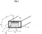
- FIG. 1 a sectional, perspective view of a first, preferred embodiment of the composite element according to the invention is shown.
- the composite element comprises a hollow profile 2 and an insert 4.
- the hollow profile encloses a cavity 6 which, in the illustrated embodiment, is essentially rectangular in cross-section perpendicular to a profile direction x.
- the cavity 6 extends in a width direction b and a height direction h.
- the insert 4 is formed from a first layer 10 and a second layer 12 .
- the first layer 10 is designed as a mass region and advantageously has a greater density than the second layer 12 .
- the second layer 12 acts accordingly as a spring damper and is advantageously formed from an impregnated foam.
- the first layer 10 can also be formed from an impregnated foam, with an impregnate being used which achieves a higher density of the first layer 10 .
- the hollow profile 2 has two opposing walls 14, 16 on which the insert 4 is supported in the decompressed state. It is particularly advantageous if the first layer 10 faces or is in contact with that wall 14 which is the wall exposed to foot traffic or environmental influences.
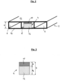
- In 2 is a second preferred embodiment of the composite element according to the invention and in 3 a preferred embodiment of a deposit shown.
- the hollow profile 2 has three cavities 6, of which only the central cavity 6 is fitted with the insert 4.
- the walls 14, 16 are spaced at a distance a from each other in the height direction h.
- the insert 4 has a thickness D, measured in the height direction h, which is greater than the distance a. Furthermore, a ratio of the thickness d 1 of the first layer 10 to the thickness d 2 of the second layer 12 is in a range of 0.6-0.75, as a result of which a particularly efficient mass-spring-damper element can be provided.
Landscapes
- Engineering & Computer Science (AREA)
- Mechanical Engineering (AREA)
- Architecture (AREA)
- Physics & Mathematics (AREA)
- Electromagnetism (AREA)
- Civil Engineering (AREA)
- Structural Engineering (AREA)
- Building Environments (AREA)
- Floor Finish (AREA)
- Laminated Bodies (AREA)
Description
- Die vorliegende Erfindung betrifft ein Verbundelement, insbesondere für Böden und Wände, die Verwendung einer Einlage in einem Hohlprofil, insbesondere für Böden und Wände, zur Absorption von Körperschall sowie ein Verfahren zur Herstellung eines Verbundelements, insbesondere für Böden und Wände.
- Verbundelemente für Flächenbereiche, wie Böden und Wände, sind hinlänglich aus dem Stand der Technik bekannt. Hierbei werden Hohlprofile, beispielsweise aus Metall derart in einen Verbund gebracht, dass diese als Boden- oder Wandbelag dienen können, beispielsweise für Balkone und Terrassen oder Zwischenböden im Gebäudeinnenraum. Problematisch bei derartigen Systemen ist jedoch, dass beim Belasten der Oberfläche, beispielsweise beim Begehen oder durch Umwelteinflüsse wie Regen oder Hagel, ein Tritt- oder Körperschall erzeugt wird, welcher als störende Lärmemission wahrgenommen wird. Um eine derartige Schallemission zu verringern, ist es bekannt, die Hohlprofile auszuschäumen oder auszugießen. Die Einlage bei den bekannten Systemen wird somit quasi in situ, d. h. unmittelbar am Ort, hergestellt und mit dem Hohlprofil verbunden. Problematisch bei derartigen Fertigungsverfahren ist jedoch, dass - da die Hohlprofile mehrere Meter lang sein können - ein hoher Fertigungsaufwand notwendig ist, um die Einlage homogen über die gesamte Länge des Hohlprofils in diesem zu erzeugen und bereit zu stellen.
-
EP 1 061 100 A1 offenbart ein Sandwichelement, welches vielschichtig, schallisolierend und mechanisch belastbar ausgelegt ist. Dabei ist ein Plastikkern mit zwei Deckschichten bedeckt, so dass eine Lücke oder eine Vielzahl an Lücken zwischen dem Plastikkern und den Schichten entsteht und somit ein schalldämpfender Effekt entsteht. Zudem ist die Plastikkernschicht aus einem porösen Material, welches zumindest 50% offene Zellen hat. - Die
DE 195 04 601 A1 betrifft ein wärmegedämmtes Verbundprofil für eine Fassadenkonstruktion, welche aus zwei im Abstand voneinander angeordneten Metallprofilen besteht und zwischen welchen ein Wärmedämmmaterial angeordnet ist. - Die
DE 199 01 086 A1 betrifft eine schalldämmende Anordnung für eine Gebäudedecke, welche eine auf der Rohdecke aufliegende Dämmschicht aufweist. - Es ist somit Aufgabe der vorliegenden Erfindung, ein Verbundelement, insbesondere für Böden und Wände, eine Verwendung einer Einlage in einem Hohlprofil, insbesondere für Böden und Wände, sowie ein Verfahren zur Herstellung eines Verbundelements, insbesondere für Böden und Wände vorzusehen, welche eine verbesserte Absorption von Körperschall sowie eine einfache und kostengünstige Fertigung ermöglichen.
- Diese Aufgabe wird durch ein Verbundelement, insbesondere für Böden und Wände, mit den Merkmalen des Anspruchs 1, eine Verwendung einer Einlage in einem Hohlprofil, insbesondere für Böden und Wände, mit den Merkmalen des Anspruchs 13 und ein Verfahren zur Herstellung eines Verbundelements, insbesondere für Böden und Wände, mit den Merkmalen des Anspruchs 14 gelöst. Bevorzugte Ausführungsformen ergeben sich aus den abhängigen Ansprüchen.
- Erfindungsgemäß ist ein Verbundelement, insbesondere für Böden und Wände, vorgesehen, umfassend ein Hohlprofil, welches einen zumindest überwiegend geschlossenen Hohlraum aufweist, eine Einlage, welche in dem Hohlraum derart angeordnet oder anordenbar ist, dass sich die Einlage an zumindest zwei gegenüberliegenden Wandungen des Hohlprofils abstützt, wobei die Einlage aus einem offenporigen Material ausgebildet ist, welches nach einer Verformung eine verzögerte Rückstellung aufweist. Das Hohlprofil ist zweckmäßigerweise als Element ausgebildet, welches eine in einer Profilrichtung im Wesentlichen konstante Querschnittsgeometrie aufweist. In einem Querschnitt senkrecht zur Profilrichtung ist das Hohlprofil zweckmäßigerweise derart ausgebildet, dass es einen zumindest überwiegend geschlossenen Hohlraum aufweist. In anderen Worten, umschließt das Hohlprofil umfänglich einen Hohlraum um mindestens 50% des Umfanges, bevorzugt um mindestens 80% des Hohlraums. So kann das Hohlprofil im Querschnitt beispielsweise die Form eines "U" aufweisen. In einer besonders bevorzugten Ausführungsform ist das Hohlprofil derart ausgebildet, dass es im Querschnitt einen Hohlraum vollständig umgibt. Es versteht sich, dass das Hohlprofil einen Hohlraum aufweisen kann, wobei das Hohlprofil auch derart ausgebildet sein kann, dass es eine Vielzahl von, insbesondere parallel oder entlang einer Geraden, angeordneten Hohlräumen aufweist. Diese können in ihrer geometrischen Gestaltung verschieden ausgebildet sein, sind jedoch in einer besonders bevorzugten Ausführungsform allesamt als geschlossener Hohlraum ausgebildet. Die Form des Hohlraums kann beliebig gestaltet sein, ist jedoch in einer bevorzugten Ausführungsform im Wesentlichen rechteckig. Insbesondere weist der Hohlraum zwei gegenüberliegende Wandungen auf. Die gegenüberliegenden Wandungen können geneigt zueinander ausgebildet sein, sind jedoch in einer bevorzugten Variante im Wesentlichen parallel zueinander ausgerichtet. Es ist besonders zweckmäßig, wenn eine der gegenüberliegenden Wandungen diejenige Wandung ist, die im Gebrauch des Verbundelements die durch äußere Einwirkungen (Begehen, Regen oder Hagel) belastete Wandung darstellt. Weiterhin ist eine Einlage vorgesehen, die in dem Hohlraum angeordnet oder anordenbar ist. Die Einlage ist hierbei derart hinsichtlich Material und/oder Geometrie gestaltet, dass sich diese an den zwei gegenüberliegenden Wandungen des Hohlprofils abstützen kann. Die Einlage stützt sich dann an den zwei gegenüberliegenden Wandungen des Hohlprofils ab, wenn diese auf die gegenüberliegenden Wandungen eine, nach außen gerichtete Kraft ausübt. Die Einlage ist hierbei derart ausgebildet, dass diese nicht, wie im Stand der Technik in dem Hohlprofil ausgebildet, bzw. hergestellt wird, sondern die Herstellung der Einlage ex situ, d. h. außerhalb des Hohlraums erfolgt. So ist es besonders vorteilhaft, dass das Hohlprofil und die Einlage zwei getrennt voneinander hergestellte Elemente sind, welche zweckmäßigerweise in einem weiteren Fertigungsschritt nach deren Herstellung miteinander verbunden werden bzw. sind. Insbesondere ist die Einlage elastisch ausgebildet. Die Einlage ist aus einem offenporigen Material ausgebildet, welches nach einer Verformung eine verzögerte Rückstellung aufweist.
- Unter dem Begriff "verzögerte Rückstellung" wird ein Aufstellen bzw. ein Rückstellen in Aufstellrichtung der eingedrückten Einlagen verstanden. In einem unbelasteten Zustand ist die Einlage bevorzugt in Ruhe, das heißt, dass die Einlage keine Rückstellung vollzieht bzw. eine Rückstellung vollständig vollzogen hat. Im unbelasteten Zustand erreicht die Einlage ihre maximale Aufstellhöhe. Die Einlage kann in einen belasteten/eingedrückten Zustand mit verringerter Aufstellhöhe durch eine Eindrückkraft gebracht werden. Dabei erstreckt sich die Eindrückkraft über Teile oder die die gesamte Fläche der Einlage und ist dabei orthogonal zu den gegenüberliegenden Wandungen angeordnet. Durch das Einwirken der Eindrückkraft auf die Einlage wird die Aufstellhöhe reduziert, was mit dem Verhältnis eingedrückte Aufstellhöhe zur maximaler Aufstellhöhe beschrieben wird. Bspw. wird die Aufstellhöhe durch das Einwirken der Eindrückkraft um 30% reduziert, was für die verzögerte Rückstellung bedeutet, dass der resultierende Rückstellweg 30% der maximalen Aufstellhöhe ist und der Rückstellweg die Differenz der Aufstellhöhe zwischen dem belastenden/eingedrückten Zustand und dem unbelasteten Zustand beschreibt. Sobald der belastete/eingedrückte Zustand aufgelöst wird, beginnt die verzögerte Rückstellung der Einlage. Aus dem belasteten/eingedrückten Zustand erreicht die Einlage wieder den unbelasteten Zustand oder bevorzugt einen weiteren Zustand, einen Zwischenzustand, welcher eine teilweise Rückstellung beschreibt. Dabei ist die Dauer der verzögerten Rückstellung erfindungsgemäß länger als die Rückstellung, welche eine Einlage ohne die Imprägnierung mit einem Bindemittel und/oder einem Füllstoff aufweist. Bevorzugterweise beträgt die verzögerte Rückstellung 10% der maximalen Aufstellhöhe pro Stunde bis 6000% der maximalen Aufstellhöhe pro Stunde bei einer Umgebungsluftfeuchtigkeit 40-60% und einer Umgebungstemperatur von ca. 20° Celsius. Der Vorteil dieser Ausführungsform ist, dass die verzögerte Rückstellung über die Imprägnierung individuell für die Anwendung angepasst werden kann. So ist beispielsweise eine schnelle Rückstellung bevorzugt, wenn lediglich die Einlage in einen Hohlraum eingebracht wird. Bevorzugterweise beträgt die verzögerte Rückstellung bevorzugt zwischen 300% und 6000%, bevorzugt zwischen 500% und 5000%, besonders bevorzugt zwischen 1000% und 3000% der maximalen Aufstellhöhe pro Stunde bei einer Umgebungsluftfeuchtigkeit 40-60% und einer Umgebungstemperatur von ca. 20° Celsius. Bei einer Kombination der Einlage mit bspw. elektronischen Komponenten ist eine sehr langsame Rückstellwirkung vorteilhaft, da genügend Zeit für die Montage der elektronischen Komponenten vorhanden sein muss. In dieser Ausführungsform beträgt die verzögerte Rückstellung zwischen 10% und 300%, bevorzugt zwischen 50% und 250%, besonders bevorzugt zwischen 100% und 175% der maximalen Aufstellhöhe pro Stunde bei einer Umgebungsluftfeuchtigkeit 40-60% und einer Umgebungstemperatur von ca. 20° Celsius. Zweckmäßigerweise lässt sich die verzögerte Rückstellung linear beschreiben, sodass bei zunehmendem Eindrücken die Rückstellzeit konstant zunimmt. In einer alternativen Ausführungsform ist die verzögerte Rückstellung durch eine exponentielle Funktion zu beschreiben, wobei die Rückstellzeit bei zunehmendem Eindrücken zunimmt. In einer weiteren Ausführungsform ist die verzögerte Rückstellung eine Kombination aus einer linearen und exponentiellen Funktion, wobei zuerst eine lineare Rückstellung und anschließend eine exponentiell verzögerte Rückstellung stattfinden. In einem Beispiel wird die Einlage um 33% ihrer maximalen Aufstellhöhe eingedrückt. Die Rückstellung beginnt in einer bevorzugten Ausführungsform sofort, jedoch spätestens nach drei Minuten, vorzugsweise eine Minute, und endet bevorzugterweise nach weniger als 24 Stunden. In einem weiteren Beispiel wird die Einlage um 35% ihrer maximalen Aufstellhöhe eingedrückt. In diesem Beispiel erfolgt die verzögerte Rückstellung in zwei Abschnitten, wobei die im ersten Abschnitt der verzögerten Rückstellung die Einlage sich um 10-40% des Rückstellwegs zurücklegt und im zweiten Abschnitt sich um 90-60% des Rückstellwegs zurücklegt. Im ersten Abschnitt beträgt die verzögerte Rückstellung bevorzugt zwischen 300% und 6000%, bevorzugt zwischen 500% und 5000%, besonders bevorzugt zwischen 1000% und 3000% der maximalen Aufstellhöhe pro Stunde bei einer Umgebungsluftfeuchtigkeit 40-60% und einer Umgebungstemperatur von ca. 20° Celsius. Im zweiten Abschnitt beträgt die verzögerte Rückstellung bevorzugt zwischen 300% und 6000%, bevorzugt zwischen 500% und 5000%, besonders bevorzugt zwischen 1000% und 3000% der maximalen Aufstellhöhe pro Stunde bei einer Umgebungsluftfeuchtigkeit 40-60% und einer Umgebungstemperatur von ca. 20° Celsius.
- Hierdurch ist es besonders vorteilhafterweise möglich, nach Herstellung der Einlage, diese zu komprimieren und im komprimierten Zustand in den Hohlraum des Hohlprofils einzuführen. Da im komprimierten Zustand der Einlage deren Erstreckung in Höhenrichtung geringer ist als der Abstand zwischen den zwei gegenüberliegenden Wandungen des Hohlprofils, ist die Einlage besonders leicht in den Hohlraum einführbar. Die Höhenrichtung ist hierbei im Wesentlichen senkrecht zu einer Breitenrichtung, welche wiederum senkrecht zur Profilrichtung stehen. Die gegenüberliegenden Wandungen erstrecken sich vorteilhafterweise im Wesentlichen entlang der Breitenrichtung, so dass diese einen bestimmten Abstand in Höhenrichtung besitzen. Durch die Ausbildung der Einlage aus einem Material, welches eine verzögerte Rückstellung aufweist, ist es vorteilhafterweise möglich, die Einlage in den Hohlraum einzubringen, wobei nach Positionierung der Einlage diese anfängt, zu expandieren, bis diese an den gegenüberliegenden Wandungen des Hohlprofils sich abstützend zur Anlage gebracht wird und auf die gegenüberliegenden Wandungen nach außen gerichtete Kraft ausübt.
- Zweckmäßigerweise ist das Hohlprofil im Wesentlichen unelastisch ausgebildet. Hierfür kann das Hohlprofil eine Geometrie aufweisen, welche gegenüber Verformung besonders widerstandsfähig ist. Bevorzugt ist das Hohlprofil aus einem im Wesentlichen unelastischen Material ausgebildet. Ein im Wesentlichen unelastisches Material weist hierbei ein Elastizitätsmodul >5000 N/mm2, vorzugsweise > 25000 N/mm2 auf. So kann das Material des Hohlprofils beispielsweise ein Metall, wie Aluminium, sein. Hierdurch wird ein besonders vorteilhaft stabiles Verbundelement ermöglicht.
- Vorteilhafterweise ist die Einlage, zumindest teilweise, aus einem Schaum ausgebildet. Der Schaum kann ein offenzelliger Polyurethan-Weichschaum sein. Die Offenzelligkeit des offenporigen Schaums erhöht vorteilhafterweise die Schallabsorptionsfähigkeit der Einlage. Besonders zweckmäßigerweise weist der Schaum ein Raumgewicht von 15 bis 50 kg/m3, vorzugsweise 25 bis 35 kg/ m3 auf. Weiterhin bevorzugt ist die Offenzelligkeit des Schaums derart ausgebildet, dass, in einem Flächenschnitt betrachtet, 5 bis 30 Zellen pro cm, vorzugsweise 15 bis 25 Zellen pro cm vorgesehen sind. Beide vorstehend genannten Parameter sind derart gewählt, dass eine besonders vorteilhafte Schallabsorptionsfähigkeit ermöglicht wird.
- Erfindungsgemäß ist die Einlage aus einem Material ausgebildet, welches zumindest teilweise mit einer Imprägnierung aus Bindemittel und Füllstoff getränkt und/oder beschichtet ist. Die Imprägnierung, bzw. das Imprägnat besteht vorteilhafterweise zu 40 bis 60% aus einem Bindemittel und zu 40 bis 60% aus mineralischen Füllstoffen. Beispielhafte Bindemittel können Polyacrylat, Kunstharz oder Synthesekautschuk sein. Beispielhafte Füllstoffe können Aluminiumhydroxid, Kalziumkarbonat, Kaolin, Magnetit oder Bariumsulfat sein. Es versteht sich, dass auch Verschnitte der jeweils genannten mineralischen Füllstoffe oder der jeweils genannten Bindemittel vorgesehen sein können. Durch die Tränkung oder Beschichtung der Einlage mit der Imprägnierung wird vorteilhafterweise eine verzögerte Rückstellung ermöglicht, da sich die Tränkung in den offenen Poren des Materials absetzt. Anders als bei einer Beschichtung, die nur oberflächlich wirkt, ist die Eindringtiefe in das Material der Einlage bei einer Tränkung sehr viel größer, so dass die Wirkung der verzögerten Rückstellung noch verstärkt werden kann.
- In einer Ausführungsform ist die Einlage aus einem homogenen Material gebildet. In anderen Worten kann die Einlage derart gestaltet sein, dass sie lediglich aus ein- und demselben offenporigen Grundmaterial gebildet ist. Bevorzugt ist das Material derart mit einer Imprägnierung getränkt, dass es auch eine homogene Verteilung eines Imprägnats aufweist. In einer alternativen Ausführungsform kann die aus einem homogenen Material bestehende Einlage auch nur bereichsweise mit einem Imprägnat getränkt oder beschichtet sein.
- In einer besonders bevorzugten Ausführungsform ist die Einlage derart ausgebildet, dass diese ein Masse-Feder-Dämpfungs-System, bzw. -Element ausbildet. Hierbei ist ein Bereich der Einlage als Massebereich ausgebildet, wobei ein zweiter, daran angrenzender Bereich der Einlage die Funktion eines Feder-Dämpfers ausfüllt, d. h. gleichzeitig eine Federkonstante und Dämpfcharakteristik aufweist. Die Feder-Charakteristik und Dämpfer-Charakteristik wirkt somit parallel, während die Masse in Reihe hierzu angeordnet ist. Hierdurch ist es besonders vorteilhaft möglich, Vibrationen und Körperschall im Verbundelement zu minimieren. Dies ist möglich, da der den Feder-Dämpfer ausbildende Bereich der Einlage eine schwingungstechnische Entkoppelung der Masse ermöglicht.
- Bevorzugt ist die Einlage aus einer Vielzahl, vorzugsweise zwei, Schichten verschiedener Materialien oder Eigenschaften ausgebildet. Dies ist dann beispielsweise der Fall, wenn die Einlage als wie vorstehend beschriebenes Masse-Feder-Dämpfungs-System ausgebildet ist. So kann eine zweite Schicht aus einem offenporigen Material mit verzögerter Rückstellung ausgebildet sein, während eine erste Schicht keine verzögerte Rückstellung aufweisen muss. Die erste Schicht kann auch als im Wesentlichen formstabiler Körper ausgebildet sein. Besonders bevorzugt ist jedoch auch die erste Schicht aus einem Material mit verzögerter Rückstellung ausgebildet. Auch ist denkbar, eine dritte Schicht vorzusehen, welche zweckmäßigerweise an der zweiten Schicht angeordnet und der ersten Schicht gegenüber liegend ist. Die dritte Schicht kann beispielsweise in Form einer Folie oder Beschichtung ausgebildet sein, die einen besonders niedrigen Reibungskoeffizienten aufweist, um die Einlage in den Hohlraum besonders einfach einbringen zu können.
- Zweckmäßigerweise ist die Einlage in dem Hohlraum derart angeordnet oder anordenbar, dass sich eine erste Schicht an einer belasteten Wandung abstützt. Die zweite Schicht ist somit derjenige Bereich der Einlage, welcher der belasteten Wandung abgewandt ist. Die belastete Wandung ist derjenige Bereich des Hohlprofils, welcher im Benutzungszustand des Verbundelements durch Betreten oder Umwelteinflüsse belastet wird.
- Zweckmäßigerweise hat eine erste Schicht ein größeres Raumgewicht als eine zweite Schicht. Hierdurch wird aufgrund des vorstehend beschriebenen FederMasse-Prinzips eine besonders vorteilhafte Verringerung von Vibration und Körperschall ermöglicht. Die Absorption von Schall ist besonders vorteilhaft, wenn die erste Schicht der belasteten Wandung zugewandt ist bzw. an dieser anliegt.
- Besonders vorteilhaft ist es hinsichtlich der Schallabsorption, wenn das Verhältnis des Raumgewichts der zweiten Schicht zur ersten Schicht zwischen 0,15 und 0,45, vorzugsweise zwischen 0,27 und 0,33 liegt. Besonders bei einem Wert zwischen 0,27 und 0,33 wirkt die Einlage als optimales Masse-Feder-Dämpfungs-System. Hierbei kann die Einlage derart ausgebildet sein, dass der Bereich der ersten Schicht ein Raumgewicht zwischen 200 und 1000 kg/m3, vorzugsweise 400 und 600 kg/m3 aufweist. Dieses Raumgewicht wird insbesondere durch die Zusammensetzung der Imprägnierung erzielt. Die zweite Schicht weist zweckmäßigerweise ein Raumgewicht zwischen 50 und 250 kg/m3, vorteilhafterweise zwischen 120 und 175 kg/m3 auf. Entsprechend ist auch dieses Raumgewicht durch die Zusammensetzung der Imprägnierung einstellbar.
- Vorteilhafterweise weisen die erste und zweite Schicht unterschiedliche Dicken auf. Auch hierdurch ist das Absorptionsverhalten der Einlage optimal einstellbar. Die Dicke ist hierbei entlang der Höhenrichtung bemessen.
- Vorteilhafterweise ist das Verhältnis der Dicke der ersten Schicht zur zweiten Schicht kleiner 1 und liegt vorzugsweise zwischen 0,3 und 0,85 und besonders bevorzugt zwischen 0,6 und 0,75. Insbesondere bei einem Verhältnis zwischen 0,3 und 0,85 ist die Dicke der zweiten Schicht in Bezug zu der Dicke der gesamten Einlage derart bemessen, dass ein möglichst großer Bereich eine verzögerte Rückstellung aufweist, wodurch eine einfache Montage der Einlage in dem Hohlprofil ermöglicht wird. Für ein optimales Schallabsorptionsverhalten hat sich ein Verhältnis zwischen 0,6 und 0,75 als besonders vorteilhaft erwiesen.
- Vorzugsweise hat eine erste Schicht eine größere Stauchhärte als eine zweite Schicht. In anderen Worten ist die Festigkeit der ersten Schicht größer als die der zweiten Schicht. Hierdurch wird eine besonders gute Anlage der ersten Schicht an der Innenoberfläche der Wandung des Hohlprofils erzielt.
- Besonders bevorzugt liegt das Verhältnis der Stauchhärte der zweiten Schicht zur Stauchhärte der ersten Schicht zwischen 0,2 und 0,8, vorzugsweise zwischen 0,3 und 0,5. Besonders bei einem Verhältnis der Stauchhärten zwischen 0,3 und 0,5 wird ein besonders optimales Absorptionsverhalten erzielt, da hier ein sehr ausgeglichenes Masse-Feder-Dämpfungs-System geschaffen ist. So kann die Stauchhärte der ersten Schicht bis zu 10 kPa und der zweiten Schicht bis zu 12 kPa nach DIN EN ISO 33861-1 bei 40% Kompression betragen.
- In einer bevorzugten Variante sind die erste und zweite Schicht vorzugsweise stoffflüssig miteinander verbunden. Die stoffschlüssige Verbindung kann beispielsweise über eine Verschweißung oder Verklebung erfolgen, wobei die stoffschlüssige Verbindung insbesondere dadurch gekennzeichnet ist, dass die erste und zweite Schicht nicht zerstörungsfrei voneinander trennbar sind. Alternativ hierzu können die erste und zweite Schicht auch nur aufeinander gelegt sein und besonders bevorzugt aufgrund einer gewissen Klebrigkeit des Imprägnats aneinander haften.
- In einer weiter bevorzugten Ausführungsform weisen die erste und/oder zweite Schicht Indikatormittel auf, die es ermöglichen, die erste und zweite Schicht voneinander zu differenzieren. Hierdurch kann besonders vorteilhafterweise sichergestellt werden, dass der Monteur die Einlage in der richtigen Orientierung im Hohlraum des Hohlprofils anordnet. Die Indikatormittel können beispielsweise derart ausgebildet sein, dass die Schichten unterschiedliche Farben aufweisen, oder an diesen Markierungen vorgesehen sind.
- Vorzugsweise liegt das Verhältnis des vom Hohlraum umschlossenen Raums zum Volumen der Einlage zwischen 0,5 und 0,95, vorzugsweise zwischen 0,7 und 0,85. Das Verhältnis ist ein einem Zustand des Verbundelements gemessen, in welchem die Einlage in dem Hohlraum des Hohlprofils angeordnet ist. Da sich die Einlage an zwei gegenüberliegenden Wandungen abstützt, erstreckt sich somit die Einlage nicht in Breitenrichtung über den gesamten Hohlraum. Es hat sich erwiesen, dass eine ausreichende Schallabsorption bei einem Volumenverhältnis zwischen 0,7 und 0,85 erzielt werden kann.
- Weiterhin bevorzugt weist das Hohlprofil eine Vielzahl von Hohlräumen und eine oder eine Vielzahl von Einlagen auf, wobei das Verhältnis des von sämtlichen Hohlräumen umschlossenen Raums zum Volumen der Einlage(n) zwischen 0,1 und 0,3, vorzugsweise zwischen 0,15 und 0,25 liegt. Ein derartiges Verhältnis ist beispielsweise erzielbar, wenn bei einem Hohlprofil mit einer Vielzahl von Hohlräumen nicht jeder Hohlraum mit der Einlage bestückt ist. So kann beispielsweise bei einem Hohlprofil mit drei Hohlräumen lediglich der mittlere Hohlraum mit der Einlage bestückt sein. Bei einem Mehrkammer-Hohlprofil mit einer Vielzahl von Hohlräumen hat sich gezeigt, dass ein Volumenverhältnis zwischen 0,1 und 0,3 ausreicht, um eine notwendige Schallabsorption zu erzielen.
- Vorzugsweise weist die Einlage im nicht im Hohlraum angeordneten Zustand eine Dicke auf, welche größer ist als der Abstand zwischen den zwei gegenüberliegenden Wandungen. Hierbei wird die Dicke der Einlage im nicht komprimierten Zustand bestimmt.
- Zweckmäßigerweise liegt das Verhältnis der Dicke der Einlage im nicht komprimierten Zustand zum Abstand der zwei gegenüberliegenden Wandungen zwischen 1,05 und 1,8, vorzugsweise zwischen 1,2 und 1,4. Es hat sich gezeigt, dass insbesondere bei einem Verhältnis zwischen 1,2 und 1,4 die Einlage im montierten und rückgestellten Zustand eine optimale Kraft auf die zwei gegenüber liegenden Wandungen ausdrückt, um somit den Körperschall optimal zu absorbieren.
- In einer bevorzugten Ausführungsform ist das Verbundelement derart gestaltet, dass die Einlage in Profil-Längsrichtung zwei gegenüberliegende Enden hat, von welchen wenigstens eines, vorzugsweise beide, in Profil-Längsrichtung zurückgebogen ist bzw. sind. In anderen Worten ist die Erstreckung der Einlage in Profilrichtung länger als die Erstreckung des Hohlprofils in Profilrichtung. Der überstehende Bereich der Einlage ist in Profilrichtung zurückgebogen, bzw. umgeklappt, bzw. umgekrempelt, so dass an den Enden des Hohlprofils ein Bereich der Einlage vorgesehen ist, in welchem diese gedoppelt ist. Hierdurch gelangt die Einlage während des Rückstellens sehr viel schneller mit den zwei gegenüberliegenden Wandungen in Eingriff und sichert somit die Lage der Einlage im Hohlprofil.
- Weiterhin erfindungsgemäß ist eine Verwendung einer Einlage in einem Hohlprofil, insbesondere für Böden und Wände, zur Absorption von Körperschall vorgesehen, wobei die Einlage aus einem offenporigen Material ausgebildet ist, welches nach einer Verformung eine verzögerte Rückstellung aufweist. Es versteht sich, dass sämtliche mit Bezug zu dem erfindungsgemäßen Verbundelement und deren bevorzugten Ausführungsformen beschriebenen Merkmale und Vorteile betreffend die Einlage und deren Anordnung im Verbundelement gleichfalls für die erfindungsgemäße Verwendung einer Einlage in einem Hohlprofil zutreffen.
- Weiterhin erfindungsgemäß ist ein Verfahren zur Herstellung eines Verbundelements, insbesondere für Böden und Wände vorgesehen, umfassend die Schritte: Bereitstellen eines Hohlprofils, welches einen zumindest überwiegend geschlossenen Hohlraum aufweist;
- Bereitstellen einer Einlage, die aus einem offenporigen Material ausgebildet ist, welches nach einer Verformung eine verzögerte Rückstellung aufweist, in einem vorkomprimierten Zustand;
- Anordnen der Einlage in deren vorkomprimierten Zustand in dem Hohlraum derart, dass sich die Einlage nach einer Dekomprimierung an zumindest zwei gegenüber liegenden Wandungen abstützt.
- In anderen Worten werden somit Hohlprofil und Einlage getrennt voneinander hergestellt und dann miteinander montiert. Die Montage der Einlage in dem Hohlprofil kann beispielsweise erfolgen, indem die Einlage in den Hohlraum des Hohlprofils eingeschoben oder eingezogen wird. Es versteht sich, dass die weiteren Merkmale und Vorteile des erfindungsgemäßen Verbundelements und dessen bevorzugte Ausführungsformen sowie der erfindungsgemäßen Verwendung einer Einlage in einem Hohlprofil gleichfalls in dem erfindungsgemäßen Verfahren Anwendung finden können.
- Weitere Merkmale und Vorteile ergeben sich aus der nachfolgenden Beschreibung von bevorzugten Ausführungsformen mit Bezug auf die beigefügten Figuren. Es zeigen:
- Fig. 1:
- eine geschnittene perspektivische Ansicht einer ersten Ausführungsform eines erfindungsgemäßen Verbundelements.
- Fig. 2:
- eine geschnittene perspektivische Ansicht einer zweiten Ausführungsform eines erfindungsgemäßen Verbundelements.
- Fig. 3:
- eine geschnittene Ansicht einer bevorzugten Ausführungsform einer Einlage im nicht montierten Zustand.
- In
Fig. 1 ist eine geschnittene, perspektivische Ansicht einer ersten, bevorzugten Ausführungsform des erfindungsgemäßen Verbundelements dargestellt. Das Verbundelement umfasst ein Hohlprofil 2 sowie eine Einlage 4. - Das Hohlprofil umschließt einen Hohlraum 6, welcher in der dargestellten Ausführungsform im Wesentlichen rechteckig in einem senkrecht zu einer Profilrichtung x stehenden Querschnitt ausgebildet ist. Der Hohlraum 6 erstreckt sich hierbei ein einer Breitenrichtung b und Höhenrichtung h.
- Die Einlage 4 ist in der dargestellten Ausführungsform aus einer ersten Schicht 10 und einer zweiten Schicht 12 ausgebildet. Die erste Schicht 10 ist hierbei als Masse-Bereich ausgebildet und weist vorteilhafterweise ein größeres Raumgewicht als die zweite Schicht 12 auf. Die zweite Schicht 12 wirkt entsprechend als Feder-Dämpfer und ist vorteilhafterweise aus einem imprägnierten Schaum ausgebildet. Auch die erste Schicht 10 kann aus einem imprägnierten Schaum ausgebildet sein, wobei ein Imprägnat verwendet ist, welches ein höheres Raumgewicht der ersten Schicht 10 erzielt.
- Das Hohlprofil 2 weist zwei gegenüberliegende Wandungen 14, 16 auf, an welchen sich die Einlage 4 im dekomprimierten Zustand abstützt. Besonders vorteilhaft ist es, wenn die erste Schicht 10 derjenigen Wandung 14 zugewandt, bzw. an dieser anliegend ist, welche die durch Betreten oder Umwelteinflüsse belastete Wandung ist.
- In
Fig. 2 ist eine zweite bevorzugte Ausführungsform des erfindungsgemäßen Verbundelements sowie inFig. 3 einer bevorzugten Ausführungsform einer Einlagen dargestellt. Im Unterschied zum Verbundsystem inFig. 1 weist das Hohlprofil 2 drei Hohlräume 6 auf, von welchen lediglich der mittlere Hohlraum 6 mit der Einlage 4 bestückt ist. - Die Wandungen 14, 16 sind in einem Abstand a voneinander in Höhenrichtung h beabstandet. Im dekomprimierten, nicht eingebauten Zustand weist die Einlage 4 eine, in Höhenrichtung h bemessene, Dicke D auf, welche größer ist als der Abstand a. Im Übrigen liegt ein Verhältnis der Dicke d1 der ersten Schicht 10 zur Dicke d2 der zweiten Schicht 12 in einem Bereich von 0,6-0,75, wodurch ein besonders effizientes Masse-Feder-Dämpfer-Element bereitgestellt werden kann.
-
- 2
- Hohlprofil
- 4
- Einlage
- 6
- Hohlraum
- 10
- erste Schicht
- 12
- zweite Schicht
- 14
- Wandung
- 16
- Wandung
- a
- Abstand
- b
- Breitenrichtung
- D, d1, d2
- Dicken
- h
- Höhenrichtung
- X
- Profilrichtung
Claims (12)
- Verbundelement, insbesondere für Böden, umfassendein Hohlprofil (2), welches einen zumindest überwiegend geschlossenen Hohlraum (6) aufweist,eine Einlage, welche in dem Hohlraum (6) derart angeordnet oder anordenbar ist, dass sich die Einlage (4) an zumindest zwei gegenüberliegenden Wandungen (14, 16) des Hohlprofils (2) abstützt,dadurch gekennzeichnet, dassdie Einlage (4) aus einem offenporigen Material ausgebildet ist, welches nach einer Verformung eine verzögerte Rückstellung aufweist,wobei die verzögerte Rückstellung ein Aufstellen oder ein Rückstellen in Aufstellrichtung der eingedrückten Einlage ist,wobei die Einlage (4) aus einem Material ausgebildet ist, welches zumindest teilweise mit einer Imprägnierung aus Bindemittel und Füllstoff getränkt und/oder beschichtet ist,wobei die Dauer der verzögerten Rückstellung länger als die Rückstellung ist, welche eine Einlage ohne die Imprägnierung mit einem Bindemittel und/oder einem Füllstoff aufweist.
- Verbundelement nach einem der vorhergehenden Ansprüche, wobei die Einlage (4) zumindest teilweise aus einem Schaum ausgebildet ist.
- Verbundelement nach einem der vorhergehenden Ansprüche, wobei die Einlage (4) aus einer Vielzahl, vorzugsweise zwei, Schichten (10, 12) verschiedener Materialien oder Eigenschaften ausgebildet ist.
- Verbundelement nach Anspruch 3, wobei die Einlage (4) in dem Hohlraum (6) derart angeordnet oder anordenbar ist, dass sich die erste Schicht (10) an einer belasteten Wandung (14) abstützt.
- Verbundelement nach einem der Ansprüche 3 oder 4, wobei eine erste Schicht (10) ein größeres Raumgewicht als eine zweite Schicht (12) hat.
- Verbundelement nach einem der Ansprüche 3 - 5, wobei die erste und zweite Schicht (10, 12) unterschiedliche Dicken (d1, d2) aufweisen.
- Verbundelement nach einem der Ansprüche 3 - 6, wobei eine erste Schicht (10) eine größere Stauchhärte als eine zweite Schicht (12) hat.
- Verbundelement nach einem der Ansprüche 3 - 7, wobei die erste und zweite Schicht (10, 12) vorzugsweise stoffschlüssig miteinander verbunden sind.
- Verbundelement nach einem der vorhergehenden Ansprüche, wobei die Einlage (4) im nicht im Hohlraum (6) angeordneten Zustand eine Dicke (D) aufweist, welche größer ist als der Abstand (a) zwischen den zwei gegenüberliegenden Wandungen (14, 16).
- Verbundelement nach einem der vorhergehenden Ansprüche, wobei die Einlage (4) in Profillängsrichtung (x) zwei gegenüberliegende Enden hat, von welchen wenigstens eines zurückgebogen ist.
- Verwendung einer Einlage (4) in einem Hohlprofil (2), insbesondere für Böden, zur Absorption von Körperschall, wobei die Einlage (4) aus einem offenporigen Material ausgebildet ist,
dadurch gekennzeichnet, dassdie Einlage (4) nach einer Verformung eine verzögerte Rückstellung aufweist,wobei die verzögerte Rückstellung ein Aufstellen oder ein Rückstellen in Aufstellrichtung der eingedrückten Einlage ist,wobei die Einlage (4) aus einem Material ausgebildet ist, welches zumindest teilweise mit einer Imprägnierung aus Bindemittel und Füllstoff getränkt und/oder beschichtet ist,wobei die Dauer der verzögerten Rückstellung länger als die Rückstellung ist, welche eine Einlage ohne die Imprägnierung mit einem Bindemittel und/oder einem Füllstoff aufweist. - Verfahren zur Herstellung eines Verbundelements, insbesondere für Böden, umfassend die Schritte:Bereitstellen eines Hohlprofils (2), welches einen zumindest überwiegend geschlossenen Hohlraum (6) aufweist,dadurch gekennzeichnet,Bereitstellen einer Einlage (4), die aus einem offenporigen Material ausgebildet ist, welches nach einer Verformung eine verzögerte Rückstellung aufweist, in einem vorkomprimierten Zustand,wobei die verzögerte Rückstellung ein Aufstellen oder ein Rückstellen in Aufstellrichtung der eingedrückten Einlage ist,wobei die Einlage (4) aus einem Material ausgebildet ist, welches zumindest teilweise mit einer Imprägnierung aus Bindemittel und Füllstoff getränkt und/oder beschichtet ist,wobei die Dauer der verzögerten Rückstellung länger als die Rückstellung ist, welche eine Einlage ohne die Imprägnierung mit einem Bindemittel und/oder einem Füllstoff aufweist,Anordnen der Einlage (4) in deren vorkomprimierten Zustand in dem Hohlraum (6) derart, dass sich die Einlage (4) nach einer Dekomprimierung an zumindest zwei gegenüberliegenden Wandungen (14, 16) des Hohlprofils (2) abstützt.
Priority Applications (1)
| Application Number | Priority Date | Filing Date | Title |
|---|---|---|---|
| PL17174921T PL3260289T3 (pl) | 2016-06-09 | 2017-06-08 | Element kompozytowy |
Applications Claiming Priority (1)
| Application Number | Priority Date | Filing Date | Title |
|---|---|---|---|
| DE102016110665.8A DE102016110665A1 (de) | 2016-06-09 | 2016-06-09 | Verbundelement |
Publications (3)
| Publication Number | Publication Date |
|---|---|
| EP3260289A1 EP3260289A1 (de) | 2017-12-27 |
| EP3260289B1 EP3260289B1 (de) | 2020-09-02 |
| EP3260289B2 true EP3260289B2 (de) | 2023-08-09 |
Family
ID=59152636
Family Applications (1)
| Application Number | Title | Priority Date | Filing Date |
|---|---|---|---|
| EP17174921.1A Active EP3260289B2 (de) | 2016-06-09 | 2017-06-08 | Verbundelement |
Country Status (3)
| Country | Link |
|---|---|
| EP (1) | EP3260289B2 (de) |
| DE (1) | DE102016110665A1 (de) |
| PL (1) | PL3260289T3 (de) |
Families Citing this family (1)
| Publication number | Priority date | Publication date | Assignee | Title |
|---|---|---|---|---|
| AT520790B1 (de) * | 2017-12-21 | 2020-01-15 | Schmidt Michael | Bauelement |
Citations (20)
| Publication number | Priority date | Publication date | Assignee | Title |
|---|---|---|---|---|
| DE1988346U (de) † | 1967-08-07 | 1968-06-27 | Chemiefac Gmbh | Plattenfoermiger schaumstoffkoerper mit verzoegerter elastizitaet. |
| EP0312937A1 (de) † | 1987-10-22 | 1989-04-26 | Irbit Research + Consulting AG | Dichtungselement |
| EP0317833A1 (de) † | 1987-11-23 | 1989-05-31 | Irbit Research + Consulting AG | Dichtungselement |
| DE9110813U1 (de) † | 1991-08-31 | 1992-12-24 | Irbit Research + Consulting Ag, Freiburg/Fribourg | Dichtleiste |
| DE4123282A1 (de) † | 1991-07-13 | 1993-01-14 | Irbit Research & Consulting Ag | Dichtelement |
| EP0427918B1 (de) † | 1989-11-11 | 1995-01-11 | Illbruck Bau-Produkte GmbH & Co. KG | Abdeckleiste zum Ankleben an Fensterrahmen oder dergleichen |
| DE19911199A1 (de) † | 1998-04-03 | 1999-10-14 | Exte Extrudertechnik Gmbh | Leiste zur Anordnung zwischen einem Fensterrahmen und einer zugeordneten Laibung |
| DE19944611A1 (de) † | 1999-09-17 | 2001-03-22 | Illbruck Gmbh | Dichtstreifen zur Abdichtung einer Fuge |
| DE10104992A1 (de) † | 2001-02-03 | 2002-08-08 | Illbruck Gmbh | Dach-Dämmelement |
| DE102004015556B4 (de) † | 2004-03-30 | 2005-12-22 | August Braun | Putzanschlussleiste für Fensterrahmen oder dgl. mit Basisteil und Anputzteil |
| DE102005057778A1 (de) † | 2005-12-02 | 2007-06-06 | August Braun | Putzabschlussleiste für eine Putzschicht auf einer Wärmedämmung |
| EP1983121A1 (de) † | 2007-04-17 | 2008-10-22 | ISO-Chemie GmbH | Imprägniertes Dichtband mit Einschnitten oder Ausnehmungen |
| DE102008025019A1 (de) † | 2008-04-28 | 2009-10-29 | Tremco Illbruck Produktion Gmbh | Fensterrahmen, Verfahren zum Einbau eines Fensters, Schaumstoff-Dichtband, Verfahren zum Abdichten eines Fensterrahmens und Behältnis mit Schaumstoff-Dichtband |
| EP2116683A2 (de) † | 2008-05-08 | 2009-11-11 | Peter Kassmannhuber | Anschlussprofil für an Dämmstofflagen mit Putz angrenzende Bauteile |
| DE102009044306A1 (de) † | 2008-10-23 | 2010-07-08 | Peter Kassmannhuber | Anschlussprofil für an Dämmstofflagen mit Putz angrenzende Bauteile |
| DE202010006506U1 (de) † | 2009-05-07 | 2010-08-19 | Vermögensverwaltung Kovac GbR (vertretungsberechtigter Gesellschafter: Franjo Kovac, 46395 Bocholt) | Optisch ansprechende Bewegungsfugenprofile mit ausgezeichneter trittfester Trittfläche, dauerhafter Abriebfestigkeit und Brand-, Schall- und Feuchtigkeitsschutz |
| WO2011141525A1 (de) † | 2010-05-11 | 2011-11-17 | Tremco Illbruck Produktion Gmbh | Verfahren und abdichtung einer bauwerksfuge und dichtelement |
| DE202011005416U1 (de) † | 2011-04-19 | 2012-07-20 | Tremco Illbruck Produktion Gmbh | Dichtstreifen |
| DE202011005415U1 (de) † | 2011-04-19 | 2012-07-20 | Tremco Illbruck Produktion Gmbh | Dichtstreifen |
| DE102013101273B4 (de) † | 2012-02-10 | 2017-03-16 | Odenwald-Chemie Gmbh | Schalldämmelement |
Family Cites Families (10)
| Publication number | Priority date | Publication date | Assignee | Title |
|---|---|---|---|---|
| DE1856717U (de) * | 1962-06-05 | 1962-08-16 | Martinus Hendrik Van Voorst | Profil zum anbringen auf der schwelle bzw. am unterriegel eines fensterrahmens aus holz. |
| DE1484273A1 (de) * | 1963-10-31 | 1969-05-08 | Otto Kreibaum | Schall- und waermedaemmendes Bauelement und Verfahren zu seiner Herstellung |
| US5484820A (en) * | 1994-08-05 | 1996-01-16 | The Dow Chemical Company | Polyurethane foam for packaging applications |
| DE19504601C2 (de) * | 1995-01-11 | 1998-04-09 | Wicona Bausysteme Gmbh | Wärmegedämmtes Verbundprofil |
| DE19901086A1 (de) * | 1999-01-14 | 2000-07-27 | Karl Goesele | Schalldämmende Anordnung für eine Gebäudedecke, insbesondere eine Holzbalkendecke |
| DE19926039C2 (de) * | 1999-06-08 | 2003-04-03 | Continental Ag | Schallabsorbierender Einbau für einen Kraftfahrzeugreifen und Kraftfahrzeugrad |
| ES2285804T3 (es) | 1999-06-09 | 2007-11-16 | Dow Deutschland Inc. | Elemento intralaminar aislante de sonido. |
| DE20021724U1 (de) * | 2000-12-21 | 2001-03-01 | R. Kohlhauer GmbH, 76571 Gaggenau | Lärmschutzwand |
| DE10222074B4 (de) * | 2002-05-17 | 2006-07-27 | Daimlerchrysler Ag | Schalldämmender Bodenbelag und Verfahren zu dessen Herstellung |
| JP5431383B2 (ja) * | 2011-02-08 | 2014-03-05 | 株式会社ノザワ | 遮音床パネルの製造方法 |
-
2016
- 2016-06-09 DE DE102016110665.8A patent/DE102016110665A1/de not_active Ceased
-
2017
- 2017-06-08 EP EP17174921.1A patent/EP3260289B2/de active Active
- 2017-06-08 PL PL17174921T patent/PL3260289T3/pl unknown
Patent Citations (20)
| Publication number | Priority date | Publication date | Assignee | Title |
|---|---|---|---|---|
| DE1988346U (de) † | 1967-08-07 | 1968-06-27 | Chemiefac Gmbh | Plattenfoermiger schaumstoffkoerper mit verzoegerter elastizitaet. |
| EP0312937A1 (de) † | 1987-10-22 | 1989-04-26 | Irbit Research + Consulting AG | Dichtungselement |
| EP0317833A1 (de) † | 1987-11-23 | 1989-05-31 | Irbit Research + Consulting AG | Dichtungselement |
| EP0427918B1 (de) † | 1989-11-11 | 1995-01-11 | Illbruck Bau-Produkte GmbH & Co. KG | Abdeckleiste zum Ankleben an Fensterrahmen oder dergleichen |
| DE4123282A1 (de) † | 1991-07-13 | 1993-01-14 | Irbit Research & Consulting Ag | Dichtelement |
| DE9110813U1 (de) † | 1991-08-31 | 1992-12-24 | Irbit Research + Consulting Ag, Freiburg/Fribourg | Dichtleiste |
| DE19911199A1 (de) † | 1998-04-03 | 1999-10-14 | Exte Extrudertechnik Gmbh | Leiste zur Anordnung zwischen einem Fensterrahmen und einer zugeordneten Laibung |
| DE19944611A1 (de) † | 1999-09-17 | 2001-03-22 | Illbruck Gmbh | Dichtstreifen zur Abdichtung einer Fuge |
| DE10104992A1 (de) † | 2001-02-03 | 2002-08-08 | Illbruck Gmbh | Dach-Dämmelement |
| DE102004015556B4 (de) † | 2004-03-30 | 2005-12-22 | August Braun | Putzanschlussleiste für Fensterrahmen oder dgl. mit Basisteil und Anputzteil |
| DE102005057778A1 (de) † | 2005-12-02 | 2007-06-06 | August Braun | Putzabschlussleiste für eine Putzschicht auf einer Wärmedämmung |
| EP1983121A1 (de) † | 2007-04-17 | 2008-10-22 | ISO-Chemie GmbH | Imprägniertes Dichtband mit Einschnitten oder Ausnehmungen |
| DE102008025019A1 (de) † | 2008-04-28 | 2009-10-29 | Tremco Illbruck Produktion Gmbh | Fensterrahmen, Verfahren zum Einbau eines Fensters, Schaumstoff-Dichtband, Verfahren zum Abdichten eines Fensterrahmens und Behältnis mit Schaumstoff-Dichtband |
| EP2116683A2 (de) † | 2008-05-08 | 2009-11-11 | Peter Kassmannhuber | Anschlussprofil für an Dämmstofflagen mit Putz angrenzende Bauteile |
| DE102009044306A1 (de) † | 2008-10-23 | 2010-07-08 | Peter Kassmannhuber | Anschlussprofil für an Dämmstofflagen mit Putz angrenzende Bauteile |
| DE202010006506U1 (de) † | 2009-05-07 | 2010-08-19 | Vermögensverwaltung Kovac GbR (vertretungsberechtigter Gesellschafter: Franjo Kovac, 46395 Bocholt) | Optisch ansprechende Bewegungsfugenprofile mit ausgezeichneter trittfester Trittfläche, dauerhafter Abriebfestigkeit und Brand-, Schall- und Feuchtigkeitsschutz |
| WO2011141525A1 (de) † | 2010-05-11 | 2011-11-17 | Tremco Illbruck Produktion Gmbh | Verfahren und abdichtung einer bauwerksfuge und dichtelement |
| DE202011005416U1 (de) † | 2011-04-19 | 2012-07-20 | Tremco Illbruck Produktion Gmbh | Dichtstreifen |
| DE202011005415U1 (de) † | 2011-04-19 | 2012-07-20 | Tremco Illbruck Produktion Gmbh | Dichtstreifen |
| DE102013101273B4 (de) † | 2012-02-10 | 2017-03-16 | Odenwald-Chemie Gmbh | Schalldämmelement |
Non-Patent Citations (14)
| Title |
|---|
| Artikelkarte Fensterleiste Stand vom 18.06.2016 † |
| Export Invoices RE 151131427470 zu LS 109 vom 08.04.2013 † |
| Export Invoices RE 151141413275 zu LS 346 vom 25.06.2013 † |
| illbruck Bauphysik 12/1994 † |
| Produktdatenblatt "Fensterleiste" illbruck Bau-Technik GmbH † |
| Produktdatenblatt "Wayback Fensterleiste" illbruck Bau-TechnikGmbH mit Datum: 31.01.2005 † |
| Sicherheitsdatenblatt DS4001001 illmod 600 2006 vom 09 08 2006 † |
| Sicherheitsdatenblatt SD4001001 illmod 600 (D-D) vom 02.03.2007 † |
| TP600 Datenblatt 03+11 † |
| TP600 Datenblatt 08/11 † |
| TP600 Datenblatt 09/03 † |
| TP600 DS GB 04/2016 † |
| Tremco illbruck. The Wavback Machme. 20 02-2007 † |
| Wayback Übersicht Leisten 28.01.2005 † |
Also Published As
| Publication number | Publication date |
|---|---|
| EP3260289B1 (de) | 2020-09-02 |
| PL3260289T3 (pl) | 2021-01-11 |
| EP3260289A1 (de) | 2017-12-27 |
| DE102016110665A1 (de) | 2017-12-14 |
Similar Documents
| Publication | Publication Date | Title |
|---|---|---|
| EP2743416B1 (de) | Dichtband mit funktionsstreifen | |
| DE102007040938A1 (de) | Wandaufbau und Wärmedämmplatte | |
| DE202009011619U1 (de) | Dichtelement | |
| EP2584134A1 (de) | Verfahren zur Abdichtung bei der Fenstersanierung | |
| DE202009008493U1 (de) | Wandaufbau und Wärmedämmplatte | |
| DE102011113287A1 (de) | Wärmedämmmodul und Verfahren zu dessen Herstellung | |
| EP3260289B2 (de) | Verbundelement | |
| EP2514902B1 (de) | Dichtstreifen | |
| EP1566264B1 (de) | Wärmedämmkörper | |
| DE202012100418U1 (de) | Gebäudefassade mit Riegelelement und Riegelelement | |
| DE60218060T3 (de) | Trennwandelement für trennwände und dergleichen mit einer füllung aus wärmeisolierendem material, insbesondere mineralwolle | |
| WO2017050768A1 (de) | Dämmstoffplatte und verfahren zur herstellung einer dämmstoffplatte | |
| DE10241231B4 (de) | Wärme- und/oder Schalldämmsystem sowie Dämmelement | |
| DE102008056594A1 (de) | Wandverkleidungselement | |
| DE10248326B4 (de) | Dämmschicht aus Mineralfasern | |
| DE10222074B4 (de) | Schalldämmender Bodenbelag und Verfahren zu dessen Herstellung | |
| AT507060B1 (de) | Profilelement mit schalldämmung | |
| DE202009010591U1 (de) | Thermisch wirksames Fassadenelement für Gebäudewände sowie System zur thermischen Isolierung einer Gebäudewand | |
| DE102014104098A1 (de) | Dichtungselement | |
| DE202006021154U1 (de) | Tür | |
| EP2899356B1 (de) | Dichtelement zum Abdichten von Fugen im Bereich von Fenstern | |
| DE202010012180U1 (de) | Dämmsystem | |
| EP3034711B1 (de) | Deckenrandschalungselement | |
| EP3543414A1 (de) | Naturfaserdämmung, gebäudeteil mit der naturfaserdämmung und verwendung der naturfaserdämmung | |
| DE102017129879A1 (de) | Dämmstoffbefestiger |
Legal Events
| Date | Code | Title | Description |
|---|---|---|---|
| PUAI | Public reference made under article 153(3) epc to a published international application that has entered the european phase |
Free format text: ORIGINAL CODE: 0009012 |
|
| STAA | Information on the status of an ep patent application or granted ep patent |
Free format text: STATUS: THE APPLICATION HAS BEEN PUBLISHED |
|
| AK | Designated contracting states |
Kind code of ref document: A1 Designated state(s): AL AT BE BG CH CY CZ DE DK EE ES FI FR GB GR HR HU IE IS IT LI LT LU LV MC MK MT NL NO PL PT RO RS SE SI SK SM TR |
|
| AX | Request for extension of the european patent |
Extension state: BA ME |
|
| STAA | Information on the status of an ep patent application or granted ep patent |
Free format text: STATUS: REQUEST FOR EXAMINATION WAS MADE |
|
| 17P | Request for examination filed |
Effective date: 20180625 |
|
| RBV | Designated contracting states (corrected) |
Designated state(s): AL AT BE BG CH CY CZ DE DK EE ES FI FR GB GR HR HU IE IS IT LI LT LU LV MC MK MT NL NO PL PT RO RS SE SI SK SM TR |
|
| STAA | Information on the status of an ep patent application or granted ep patent |
Free format text: STATUS: EXAMINATION IS IN PROGRESS |
|
| 17Q | First examination report despatched |
Effective date: 20190912 |
|
| GRAP | Despatch of communication of intention to grant a patent |
Free format text: ORIGINAL CODE: EPIDOSNIGR1 |
|
| STAA | Information on the status of an ep patent application or granted ep patent |
Free format text: STATUS: GRANT OF PATENT IS INTENDED |
|
| INTG | Intention to grant announced |
Effective date: 20200403 |
|
| GRAS | Grant fee paid |
Free format text: ORIGINAL CODE: EPIDOSNIGR3 |
|
| GRAA | (expected) grant |
Free format text: ORIGINAL CODE: 0009210 |
|
| STAA | Information on the status of an ep patent application or granted ep patent |
Free format text: STATUS: THE PATENT HAS BEEN GRANTED |
|
| AK | Designated contracting states |
Kind code of ref document: B1 Designated state(s): AL AT BE BG CH CY CZ DE DK EE ES FI FR GB GR HR HU IE IS IT LI LT LU LV MC MK MT NL NO PL PT RO RS SE SI SK SM TR |
|
| REG | Reference to a national code |
Ref country code: GB Ref legal event code: FG4D Free format text: NOT ENGLISH |
|
| REG | Reference to a national code |
Ref country code: AT Ref legal event code: REF Ref document number: 1308364 Country of ref document: AT Kind code of ref document: T Effective date: 20200915 Ref country code: CH Ref legal event code: EP |
|
| REG | Reference to a national code |
Ref country code: DE Ref legal event code: R096 Ref document number: 502017006999 Country of ref document: DE |
|
| REG | Reference to a national code |
Ref country code: IE Ref legal event code: FG4D Free format text: LANGUAGE OF EP DOCUMENT: GERMAN |
|
| REG | Reference to a national code |
Ref country code: CH Ref legal event code: NV Representative=s name: HEPP WENGER RYFFEL AG, CH |
|
| REG | Reference to a national code |
Ref country code: LT Ref legal event code: MG4D |
|
| PG25 | Lapsed in a contracting state [announced via postgrant information from national office to epo] |
Ref country code: BG Free format text: LAPSE BECAUSE OF FAILURE TO SUBMIT A TRANSLATION OF THE DESCRIPTION OR TO PAY THE FEE WITHIN THE PRESCRIBED TIME-LIMIT Effective date: 20201202 Ref country code: LT Free format text: LAPSE BECAUSE OF FAILURE TO SUBMIT A TRANSLATION OF THE DESCRIPTION OR TO PAY THE FEE WITHIN THE PRESCRIBED TIME-LIMIT Effective date: 20200902 Ref country code: HR Free format text: LAPSE BECAUSE OF FAILURE TO SUBMIT A TRANSLATION OF THE DESCRIPTION OR TO PAY THE FEE WITHIN THE PRESCRIBED TIME-LIMIT Effective date: 20200902 Ref country code: SE Free format text: LAPSE BECAUSE OF FAILURE TO SUBMIT A TRANSLATION OF THE DESCRIPTION OR TO PAY THE FEE WITHIN THE PRESCRIBED TIME-LIMIT Effective date: 20200902 Ref country code: NO Free format text: LAPSE BECAUSE OF FAILURE TO SUBMIT A TRANSLATION OF THE DESCRIPTION OR TO PAY THE FEE WITHIN THE PRESCRIBED TIME-LIMIT Effective date: 20201202 Ref country code: FI Free format text: LAPSE BECAUSE OF FAILURE TO SUBMIT A TRANSLATION OF THE DESCRIPTION OR TO PAY THE FEE WITHIN THE PRESCRIBED TIME-LIMIT Effective date: 20200902 Ref country code: GR Free format text: LAPSE BECAUSE OF FAILURE TO SUBMIT A TRANSLATION OF THE DESCRIPTION OR TO PAY THE FEE WITHIN THE PRESCRIBED TIME-LIMIT Effective date: 20201203 |
|
| REG | Reference to a national code |
Ref country code: NL Ref legal event code: MP Effective date: 20200902 |
|
| PG25 | Lapsed in a contracting state [announced via postgrant information from national office to epo] |
Ref country code: RS Free format text: LAPSE BECAUSE OF FAILURE TO SUBMIT A TRANSLATION OF THE DESCRIPTION OR TO PAY THE FEE WITHIN THE PRESCRIBED TIME-LIMIT Effective date: 20200902 Ref country code: LV Free format text: LAPSE BECAUSE OF FAILURE TO SUBMIT A TRANSLATION OF THE DESCRIPTION OR TO PAY THE FEE WITHIN THE PRESCRIBED TIME-LIMIT Effective date: 20200902 |
|
| PG25 | Lapsed in a contracting state [announced via postgrant information from national office to epo] |
Ref country code: EE Free format text: LAPSE BECAUSE OF FAILURE TO SUBMIT A TRANSLATION OF THE DESCRIPTION OR TO PAY THE FEE WITHIN THE PRESCRIBED TIME-LIMIT Effective date: 20200902 Ref country code: SM Free format text: LAPSE BECAUSE OF FAILURE TO SUBMIT A TRANSLATION OF THE DESCRIPTION OR TO PAY THE FEE WITHIN THE PRESCRIBED TIME-LIMIT Effective date: 20200902 Ref country code: RO Free format text: LAPSE BECAUSE OF FAILURE TO SUBMIT A TRANSLATION OF THE DESCRIPTION OR TO PAY THE FEE WITHIN THE PRESCRIBED TIME-LIMIT Effective date: 20200902 Ref country code: PT Free format text: LAPSE BECAUSE OF FAILURE TO SUBMIT A TRANSLATION OF THE DESCRIPTION OR TO PAY THE FEE WITHIN THE PRESCRIBED TIME-LIMIT Effective date: 20210104 Ref country code: CZ Free format text: LAPSE BECAUSE OF FAILURE TO SUBMIT A TRANSLATION OF THE DESCRIPTION OR TO PAY THE FEE WITHIN THE PRESCRIBED TIME-LIMIT Effective date: 20200902 |
|
| PG25 | Lapsed in a contracting state [announced via postgrant information from national office to epo] |
Ref country code: IS Free format text: LAPSE BECAUSE OF FAILURE TO SUBMIT A TRANSLATION OF THE DESCRIPTION OR TO PAY THE FEE WITHIN THE PRESCRIBED TIME-LIMIT Effective date: 20210102 Ref country code: ES Free format text: LAPSE BECAUSE OF FAILURE TO SUBMIT A TRANSLATION OF THE DESCRIPTION OR TO PAY THE FEE WITHIN THE PRESCRIBED TIME-LIMIT Effective date: 20200902 Ref country code: AL Free format text: LAPSE BECAUSE OF FAILURE TO SUBMIT A TRANSLATION OF THE DESCRIPTION OR TO PAY THE FEE WITHIN THE PRESCRIBED TIME-LIMIT Effective date: 20200902 |
|
| REG | Reference to a national code |
Ref country code: DE Ref legal event code: R026 Ref document number: 502017006999 Country of ref document: DE |
|
| PLBI | Opposition filed |
Free format text: ORIGINAL CODE: 0009260 |
|
| PLAX | Notice of opposition and request to file observation + time limit sent |
Free format text: ORIGINAL CODE: EPIDOSNOBS2 |
|
| PG25 | Lapsed in a contracting state [announced via postgrant information from national office to epo] |
Ref country code: SK Free format text: LAPSE BECAUSE OF FAILURE TO SUBMIT A TRANSLATION OF THE DESCRIPTION OR TO PAY THE FEE WITHIN THE PRESCRIBED TIME-LIMIT Effective date: 20200902 |
|
| 26 | Opposition filed |
Opponent name: TREMCO CPG GERMANY GMBH Effective date: 20210602 |
|
| PG25 | Lapsed in a contracting state [announced via postgrant information from national office to epo] |
Ref country code: SI Free format text: LAPSE BECAUSE OF FAILURE TO SUBMIT A TRANSLATION OF THE DESCRIPTION OR TO PAY THE FEE WITHIN THE PRESCRIBED TIME-LIMIT Effective date: 20200902 Ref country code: DK Free format text: LAPSE BECAUSE OF FAILURE TO SUBMIT A TRANSLATION OF THE DESCRIPTION OR TO PAY THE FEE WITHIN THE PRESCRIBED TIME-LIMIT Effective date: 20200902 |
|
| PG25 | Lapsed in a contracting state [announced via postgrant information from national office to epo] |
Ref country code: IT Free format text: LAPSE BECAUSE OF FAILURE TO SUBMIT A TRANSLATION OF THE DESCRIPTION OR TO PAY THE FEE WITHIN THE PRESCRIBED TIME-LIMIT Effective date: 20200902 |
|
| PLBB | Reply of patent proprietor to notice(s) of opposition received |
Free format text: ORIGINAL CODE: EPIDOSNOBS3 |
|
| PG25 | Lapsed in a contracting state [announced via postgrant information from national office to epo] |
Ref country code: MC Free format text: LAPSE BECAUSE OF FAILURE TO SUBMIT A TRANSLATION OF THE DESCRIPTION OR TO PAY THE FEE WITHIN THE PRESCRIBED TIME-LIMIT Effective date: 20200902 |
|
| REG | Reference to a national code |
Ref country code: BE Ref legal event code: MM Effective date: 20210630 |
|
| PG25 | Lapsed in a contracting state [announced via postgrant information from national office to epo] |
Ref country code: LU Free format text: LAPSE BECAUSE OF NON-PAYMENT OF DUE FEES Effective date: 20210608 |
|
| PG25 | Lapsed in a contracting state [announced via postgrant information from national office to epo] |
Ref country code: IE Free format text: LAPSE BECAUSE OF NON-PAYMENT OF DUE FEES Effective date: 20210608 |
|
| PG25 | Lapsed in a contracting state [announced via postgrant information from national office to epo] |
Ref country code: BE Free format text: LAPSE BECAUSE OF NON-PAYMENT OF DUE FEES Effective date: 20210630 |
|
| PGFP | Annual fee paid to national office [announced via postgrant information from national office to epo] |
Ref country code: PL Payment date: 20220526 Year of fee payment: 6 |
|
| PG25 | Lapsed in a contracting state [announced via postgrant information from national office to epo] |
Ref country code: HU Free format text: LAPSE BECAUSE OF FAILURE TO SUBMIT A TRANSLATION OF THE DESCRIPTION OR TO PAY THE FEE WITHIN THE PRESCRIBED TIME-LIMIT; INVALID AB INITIO Effective date: 20170608 |
|
| P01 | Opt-out of the competence of the unified patent court (upc) registered |
Effective date: 20230414 |
|
| PG25 | Lapsed in a contracting state [announced via postgrant information from national office to epo] |
Ref country code: NL Free format text: LAPSE BECAUSE OF NON-PAYMENT OF DUE FEES Effective date: 20200923 Ref country code: CY Free format text: LAPSE BECAUSE OF FAILURE TO SUBMIT A TRANSLATION OF THE DESCRIPTION OR TO PAY THE FEE WITHIN THE PRESCRIBED TIME-LIMIT Effective date: 20200902 |
|
| PUAH | Patent maintained in amended form |
Free format text: ORIGINAL CODE: 0009272 |
|
| STAA | Information on the status of an ep patent application or granted ep patent |
Free format text: STATUS: PATENT MAINTAINED AS AMENDED |
|
| 27A | Patent maintained in amended form |
Effective date: 20230809 |
|
| AK | Designated contracting states |
Kind code of ref document: B2 Designated state(s): AL AT BE BG CH CY CZ DE DK EE ES FI FR GB GR HR HU IE IS IT LI LT LU LV MC MK MT NL NO PL PT RO RS SE SI SK SM TR |
|
| REG | Reference to a national code |
Ref country code: DE Ref legal event code: R102 Ref document number: 502017006999 Country of ref document: DE |
|
| PG25 | Lapsed in a contracting state [announced via postgrant information from national office to epo] |
Ref country code: MK Free format text: LAPSE BECAUSE OF FAILURE TO SUBMIT A TRANSLATION OF THE DESCRIPTION OR TO PAY THE FEE WITHIN THE PRESCRIBED TIME-LIMIT Effective date: 20200902 |
|
| PGFP | Annual fee paid to national office [announced via postgrant information from national office to epo] |
Ref country code: GB Payment date: 20240620 Year of fee payment: 8 |
|
| PGFP | Annual fee paid to national office [announced via postgrant information from national office to epo] |
Ref country code: DE Payment date: 20240409 Year of fee payment: 8 |
|
| PGFP | Annual fee paid to national office [announced via postgrant information from national office to epo] |
Ref country code: AT Payment date: 20240617 Year of fee payment: 8 |
|
| PGFP | Annual fee paid to national office [announced via postgrant information from national office to epo] |
Ref country code: FR Payment date: 20240624 Year of fee payment: 8 |
|
| PG25 | Lapsed in a contracting state [announced via postgrant information from national office to epo] |
Ref country code: MT Free format text: LAPSE BECAUSE OF FAILURE TO SUBMIT A TRANSLATION OF THE DESCRIPTION OR TO PAY THE FEE WITHIN THE PRESCRIBED TIME-LIMIT Effective date: 20200902 |
|
| PGFP | Annual fee paid to national office [announced via postgrant information from national office to epo] |
Ref country code: CH Payment date: 20240701 Year of fee payment: 8 |
|
| PG25 | Lapsed in a contracting state [announced via postgrant information from national office to epo] |
Ref country code: TR Free format text: LAPSE BECAUSE OF FAILURE TO SUBMIT A TRANSLATION OF THE DESCRIPTION OR TO PAY THE FEE WITHIN THE PRESCRIBED TIME-LIMIT Effective date: 20200902 |
|
| REG | Reference to a national code |
Ref country code: DE Ref legal event code: R119 Ref document number: 502017006999 Country of ref document: DE |
|
| PG25 | Lapsed in a contracting state [announced via postgrant information from national office to epo] |
Ref country code: PL Free format text: LAPSE BECAUSE OF NON-PAYMENT OF DUE FEES Effective date: 20230608 |
|
| REG | Reference to a national code |
Ref country code: CH Ref legal event code: H13 Free format text: ST27 STATUS EVENT CODE: U-0-0-H10-H13 (AS PROVIDED BY THE NATIONAL OFFICE) Effective date: 20260127 |
|
| REG | Reference to a national code |
Ref country code: AT Ref legal event code: MM01 Ref document number: 1308364 Country of ref document: AT Kind code of ref document: T Effective date: 20250608 |
|
| GBPC | Gb: european patent ceased through non-payment of renewal fee |
Effective date: 20250608 |
|
| PG25 | Lapsed in a contracting state [announced via postgrant information from national office to epo] |
Ref country code: GB Free format text: LAPSE BECAUSE OF NON-PAYMENT OF DUE FEES Effective date: 20250608 |
|
| PG25 | Lapsed in a contracting state [announced via postgrant information from national office to epo] |
Ref country code: DE Free format text: LAPSE BECAUSE OF NON-PAYMENT OF DUE FEES Effective date: 20260101 |
|
| PG25 | Lapsed in a contracting state [announced via postgrant information from national office to epo] |
Ref country code: AT Free format text: LAPSE BECAUSE OF NON-PAYMENT OF DUE FEES Effective date: 20250608 |
|
| PG25 | Lapsed in a contracting state [announced via postgrant information from national office to epo] |
Ref country code: FR Free format text: LAPSE BECAUSE OF NON-PAYMENT OF DUE FEES Effective date: 20250630 |