EP0312937A1 - Dichtungselement - Google Patents
Dichtungselement Download PDFInfo
- Publication number
- EP0312937A1 EP0312937A1 EP88117173A EP88117173A EP0312937A1 EP 0312937 A1 EP0312937 A1 EP 0312937A1 EP 88117173 A EP88117173 A EP 88117173A EP 88117173 A EP88117173 A EP 88117173A EP 0312937 A1 EP0312937 A1 EP 0312937A1
- Authority
- EP
- European Patent Office
- Prior art keywords
- sealing element
- heat
- foam
- sealing
- expanding
- Prior art date
- Legal status (The legal status is an assumption and is not a legal conclusion. Google has not performed a legal analysis and makes no representation as to the accuracy of the status listed.)
- Granted
Links
- 238000007789 sealing Methods 0.000 title claims abstract description 43
- 238000009827 uniform distribution Methods 0.000 claims abstract description 4
- 230000003111 delayed effect Effects 0.000 claims abstract description 3
- 229920001084 poly(chloroprene) Polymers 0.000 claims abstract description 3
- 239000006260 foam Substances 0.000 claims description 29
- 230000006835 compression Effects 0.000 claims description 7
- 238000007906 compression Methods 0.000 claims description 7
- 239000002313 adhesive film Substances 0.000 claims description 5
- 239000000463 material Substances 0.000 claims description 5
- 238000009825 accumulation Methods 0.000 claims description 2
- 230000035508 accumulation Effects 0.000 claims description 2
- 239000012188 paraffin wax Substances 0.000 claims description 2
- 239000011148 porous material Substances 0.000 claims description 2
- 238000011084 recovery Methods 0.000 claims description 2
- 150000001875 compounds Chemical class 0.000 abstract description 9
- 239000011449 brick Substances 0.000 abstract 1
- 239000010425 asbestos Substances 0.000 description 6
- 229910052895 riebeckite Inorganic materials 0.000 description 6
- 239000003795 chemical substances by application Substances 0.000 description 3
- 230000000694 effects Effects 0.000 description 3
- 238000004519 manufacturing process Methods 0.000 description 2
- 238000000034 method Methods 0.000 description 2
- 230000008569 process Effects 0.000 description 2
- 239000004114 Ammonium polyphosphate Substances 0.000 description 1
- 230000001944 accentuation Effects 0.000 description 1
- 235000019826 ammonium polyphosphate Nutrition 0.000 description 1
- 229920001276 ammonium polyphosphate Polymers 0.000 description 1
- 230000008901 benefit Effects 0.000 description 1
- 230000008859 change Effects 0.000 description 1
- 238000006243 chemical reaction Methods 0.000 description 1
- 239000011248 coating agent Substances 0.000 description 1
- 238000000576 coating method Methods 0.000 description 1
- 238000010276 construction Methods 0.000 description 1
- 238000013461 design Methods 0.000 description 1
- 239000006185 dispersion Substances 0.000 description 1
- 238000009826 distribution Methods 0.000 description 1
- 238000001035 drying Methods 0.000 description 1
- 230000002349 favourable effect Effects 0.000 description 1
- 230000009970 fire resistant effect Effects 0.000 description 1
- 239000003063 flame retardant Substances 0.000 description 1
- 239000006261 foam material Substances 0.000 description 1
- 239000003292 glue Substances 0.000 description 1
- 230000001771 impaired effect Effects 0.000 description 1
- 238000005470 impregnation Methods 0.000 description 1
- 230000001788 irregular Effects 0.000 description 1
- 239000007788 liquid Substances 0.000 description 1
- 239000000203 mixture Substances 0.000 description 1
- 230000035515 penetration Effects 0.000 description 1
- 229920000642 polymer Polymers 0.000 description 1
- 238000012545 processing Methods 0.000 description 1
- 230000004044 response Effects 0.000 description 1
- 230000000717 retained effect Effects 0.000 description 1
- 239000000565 sealant Substances 0.000 description 1
- 239000003566 sealing material Substances 0.000 description 1
- 239000007787 solid Substances 0.000 description 1
- 238000013517 stratification Methods 0.000 description 1
- 238000012546 transfer Methods 0.000 description 1
- 230000007704 transition Effects 0.000 description 1
- 238000002834 transmittance Methods 0.000 description 1
- 150000003672 ureas Chemical class 0.000 description 1
Images


Classifications
-
- E—FIXED CONSTRUCTIONS
- E04—BUILDING
- E04B—GENERAL BUILDING CONSTRUCTIONS; WALLS, e.g. PARTITIONS; ROOFS; FLOORS; CEILINGS; INSULATION OR OTHER PROTECTION OF BUILDINGS
- E04B1/00—Constructions in general; Structures which are not restricted either to walls, e.g. partitions, or floors or ceilings or roofs
- E04B1/62—Insulation or other protection; Elements or use of specified material therefor
- E04B1/66—Sealings
- E04B1/68—Sealings of joints, e.g. expansion joints
- E04B1/6812—Compressable seals of solid form
-
- E—FIXED CONSTRUCTIONS
- E04—BUILDING
- E04B—GENERAL BUILDING CONSTRUCTIONS; WALLS, e.g. PARTITIONS; ROOFS; FLOORS; CEILINGS; INSULATION OR OTHER PROTECTION OF BUILDINGS
- E04B1/00—Constructions in general; Structures which are not restricted either to walls, e.g. partitions, or floors or ceilings or roofs
- E04B1/62—Insulation or other protection; Elements or use of specified material therefor
- E04B1/92—Protection against other undesired influences or dangers
- E04B1/94—Protection against other undesired influences or dangers against fire
- E04B1/948—Fire-proof sealings or joints
-
- Y—GENERAL TAGGING OF NEW TECHNOLOGICAL DEVELOPMENTS; GENERAL TAGGING OF CROSS-SECTIONAL TECHNOLOGIES SPANNING OVER SEVERAL SECTIONS OF THE IPC; TECHNICAL SUBJECTS COVERED BY FORMER USPC CROSS-REFERENCE ART COLLECTIONS [XRACs] AND DIGESTS
- Y10—TECHNICAL SUBJECTS COVERED BY FORMER USPC
- Y10S—TECHNICAL SUBJECTS COVERED BY FORMER USPC CROSS-REFERENCE ART COLLECTIONS [XRACs] AND DIGESTS
- Y10S428/00—Stock material or miscellaneous articles
- Y10S428/92—Fire or heat protection feature
- Y10S428/921—Fire or flameproofing
-
- Y—GENERAL TAGGING OF NEW TECHNOLOGICAL DEVELOPMENTS; GENERAL TAGGING OF CROSS-SECTIONAL TECHNOLOGIES SPANNING OVER SEVERAL SECTIONS OF THE IPC; TECHNICAL SUBJECTS COVERED BY FORMER USPC CROSS-REFERENCE ART COLLECTIONS [XRACs] AND DIGESTS
- Y10—TECHNICAL SUBJECTS COVERED BY FORMER USPC
- Y10T—TECHNICAL SUBJECTS COVERED BY FORMER US CLASSIFICATION
- Y10T428/00—Stock material or miscellaneous articles
- Y10T428/19—Sheets or webs edge spliced or joined
-
- Y—GENERAL TAGGING OF NEW TECHNOLOGICAL DEVELOPMENTS; GENERAL TAGGING OF CROSS-SECTIONAL TECHNOLOGIES SPANNING OVER SEVERAL SECTIONS OF THE IPC; TECHNICAL SUBJECTS COVERED BY FORMER USPC CROSS-REFERENCE ART COLLECTIONS [XRACs] AND DIGESTS
- Y10—TECHNICAL SUBJECTS COVERED BY FORMER USPC
- Y10T—TECHNICAL SUBJECTS COVERED BY FORMER US CLASSIFICATION
- Y10T428/00—Stock material or miscellaneous articles
- Y10T428/249921—Web or sheet containing structurally defined element or component
- Y10T428/249953—Composite having voids in a component [e.g., porous, cellular, etc.]
- Y10T428/249954—With chemically effective material or specified gas other than air, N, or carbon dioxide in void-containing component
-
- Y—GENERAL TAGGING OF NEW TECHNOLOGICAL DEVELOPMENTS; GENERAL TAGGING OF CROSS-SECTIONAL TECHNOLOGIES SPANNING OVER SEVERAL SECTIONS OF THE IPC; TECHNICAL SUBJECTS COVERED BY FORMER USPC CROSS-REFERENCE ART COLLECTIONS [XRACs] AND DIGESTS
- Y10—TECHNICAL SUBJECTS COVERED BY FORMER USPC
- Y10T—TECHNICAL SUBJECTS COVERED BY FORMER US CLASSIFICATION
- Y10T428/00—Stock material or miscellaneous articles
- Y10T428/249921—Web or sheet containing structurally defined element or component
- Y10T428/249953—Composite having voids in a component [e.g., porous, cellular, etc.]
- Y10T428/249982—With component specified as adhesive or bonding agent
- Y10T428/249983—As outermost component
-
- Y—GENERAL TAGGING OF NEW TECHNOLOGICAL DEVELOPMENTS; GENERAL TAGGING OF CROSS-SECTIONAL TECHNOLOGIES SPANNING OVER SEVERAL SECTIONS OF THE IPC; TECHNICAL SUBJECTS COVERED BY FORMER USPC CROSS-REFERENCE ART COLLECTIONS [XRACs] AND DIGESTS
- Y10—TECHNICAL SUBJECTS COVERED BY FORMER USPC
- Y10T—TECHNICAL SUBJECTS COVERED BY FORMER US CLASSIFICATION
- Y10T428/00—Stock material or miscellaneous articles
- Y10T428/249921—Web or sheet containing structurally defined element or component
- Y10T428/249953—Composite having voids in a component [e.g., porous, cellular, etc.]
- Y10T428/249986—Void-containing component contains also a solid fiber or solid particle
Definitions
- Such known sealing elements are associated with various disadvantages.
- the known sealing elements in particular also do not have a satisfactory fit in the joints. From a fire protection point of view, this is extremely unsatisfactory, since even one or a few places where heat or flames can penetrate destroy the fire protection effect.
- the known sealing elements are difficult to process, for example in the case of irregular joint widths. An elaborate flank pretreatment of the joints is sometimes required such. It is also of particular importance that it cannot be checked whether there is sufficient asbestos or heat-expanding sealing compound in the joints to be protected.
- the known sealing elements cause quite high costs, if only because of the circumstances mentioned, but also because of their manufacturing costs themselves.
- the object of the invention is to design and develop the known sealing elements for walls, wall openings or the like, which are subject to special fire protection requirements, in such a way that a higher level of fire safety is provided while being more cost-effective to manufacture and process.
- the conversion takes place over the depth only over a relatively short length, precisely because of the possible very rapid and comprehensive response of the heat-expanding mass to the thermal exposure.
- the pore-like perforation of the heat-expanding mass given by the foam structure also has an advantageous effect in the unloaded state, since it is not only the cause of the surface enlargement mentioned, but also gives the individual mass nests an initially unimpeded expansion possibility.
- thermal transmittance of a joint with such a sealing element is very small, even when exposed to temperatures in the range of 800 ° C or more.
- the favorable heat transfer properties of the open-cell foam material are essentially retained. It is also achieved due to the uniform penetration of the foam with the heat-expandable mass that this is finally present in the joints in a very uniform distribution.
- the pre-compression of the foam tape is preferably in the range of 50%.
- an optimal relationship between enforcement of the foam with heat-expanding Mass and advantageous insertability can be found in the joints.
- the heat-expanding mass is distributed in such a way that it coats the foam structure as it were, but moreover is also present in granular structure in individual pores of the foam.
- this can be achieved by impregnating the foam with the heat-expanding material in the liquid state and then drying it out.
- the heat-expanding material can be mixed or permeated with the impregnating agent, as explained in detail above, in the form of a dispersion.
- the foam strip is provided on one side with a self-adhesive film in its longitudinal direction. This can be used to glue it into a joint for processing.
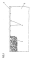
- a sealing element 1 according to the invention is initially shown and described in cross-section in FIG.
- the sealing element 1 consists of a foam strip 2 with a self-adhesive film 3 applied on one side in its longitudinal direction.
- the self-adhesive film 3 is firmly anchored in the foam strip 2 at points 4.
- the foam strip 2 is impregnated in a known manner and also interspersed with heat-expanding sealing compound, intumescent compound, in an essentially uniform distribution.
- the heat-expanding sealing compound is on the one hand in the form of a coating on the foam structure, but also in the form of mass nests (5) in which the heat-expanding compound is combined has clenched.
- the sealing element 1 is shown in a state installed in a joint.
- the sealing element 1 after resetting in the width direction x of the joint, which also corresponds to the direction of the pre-compression of the foam strip 2, is easier to compress or compress than in the depth direction of the joint y.
- a sealing element 1 according to the invention When a sealing element 1 according to the invention is subjected to heat or flames of high temperature, that is to say, for example, in the range of 800 ° C. or higher, the layer 6 of converted heat-expanding mass shown in FIG. It has been assumed here that the heat is applied to that side of the sealing element 1 which corresponds to the layer 6. As is also emphasized on the drawing, the thickness of the layer 6 (depth direction y) is relatively small. This layer 6 is followed by a transition region 7, in which the foam has partially melted or evaporated, but the heat-expanding mass has not yet been converted. This applies to temperatures in the range from approximately 200 ° C. to 800 ° C. This is followed by a further region 8, in which the sealing element 1 is practically unaffected.
- the sealing element 1 is provided on one side with an adhesive film 3.
- FIG. 3 shows a sealing element 1 in a commercially rolled-up form, it being in its pre-compressed state.
- spiral accentuations 9 it is only intended to indicate that a sealing element 1 according to the invention has a certain layer-like accumulation of heat-expandable mass.
- nerischer representation is very exaggerated in this regard.
Landscapes
- Engineering & Computer Science (AREA)
- Architecture (AREA)
- Physics & Mathematics (AREA)
- Electromagnetism (AREA)
- Civil Engineering (AREA)
- Structural Engineering (AREA)
- Sealing Material Composition (AREA)
- Building Environments (AREA)
- Glass Compositions (AREA)
- Burglar Alarm Systems (AREA)
- Diaphragms For Electromechanical Transducers (AREA)
Abstract
Description
- Zur Abdichtung von Anschlußfugen, Dehnungsfugen ect. bei Brandabschnitten, Brandwänden und Mauerdurchbrüchen (vergleiche auch DIN 4102) ist es bislang bekannt, Mittel auf Asbestbasis oder auf der Basis von wärmeexpandierenden Dichtmassen, z. B. Fomox, einzusetzen. Ein derartiges Mittel auf Asbestbasis ist beispielsweise unter dem Handelsnamen "Litaflex" bekannt. Darüber hinaus ist es auch bekannt, Asbest in Form eines Asbestzopfes in derartige Fugen einzubringen.
- Solche bekannten Dichtungselemente sind mit verschiedenen Nachteilen verbunden. Zunächst besteht grundsätzlich ein Bemühen, den Einsatz von Asbeststoffen wegen der bekannten gesundheitsgefährdenden Eigenschaften zurückzudrängen. Darüberhinaus weisen die bekannten Dichtungselemente insbesondere auch keinen zufriedenstellenden Sitz in den Fugen auf. Unter brandschutztechnischen Aspekten ist dies äußerst unbefriedigend, da bereits eine oder wenige Stellen, an denen Hitze oder Flammen durchschlagen können, den Brandschutzeffekt zunichte machen. Weiterhin sind die bekannten Dichtungselemente etwa bei unregelmäßigen Fugenbreiten nur unter größeren Schwierigkeiten zu verarbeiten. Es ist mitunter eine aufwendige Flankenvorbehandlung der Fugen erfor derlich. Von besonderer Bedeutung ist auch, daß nicht kontrollierbar ist, ob genügend Asbestmasse bzw. wärmeexpandierende Dichtmasse sich in den zu schützenden Fugen befindet. Insgesamt verursachen die bekannten Dichtelemente, schon aufgrund der genannten Umstände aber auch wegen ihrer Herstellungskosten selbst, recht hohe Kosten.
- Andererseits ist es bereits seit längerem bekannt, zur Abdichtung von Fugen in Bausektor vorkomprimierte Schaumstoffbänder zu verwenden (vergleiche beispielsweise Zeitschrift "Kunststoff im Bau" 15. Jahrg. 1980 Heft 2, Seite 66 bis 68). Wenn auch die Imprägnierung, gewöhnlich mit einem Chlorparaffin/Neopren-Gemisch, bei derartigen Schaumstoffbändern nicht nur für die verzögerte Rückstellung ursächlich ist, sondern auch eine feuerhemmende Eigenschaft verleiht, ist damit jedoch keine Einsatzmöglichkeit solcher Schaumstoffbänder bei Beaufschlagung mit hohen Temperaturen, etwa im Bereich von 800° C, verbunden. Bei Temperaturen oberhalb von etwa 200° C beginnt der Schaumstoff nämlich zu schmelzen und zu verdampfen.
- Ausgehend von den vorbeschriebenen Stand der Technik stellt sich der Erfindung die Aufgabe, die bekannten Dichtungselemente für Wände, Mauerdurchbrüche oder dergleichen, die besonderen Brandschutzanforderungen unterliegen, so auszugestalten und weiterzubilden, daß bei kostengünstigerer Herstell- und Verarbeitbarkeit gleichzeitig eine höhere Brandschutzsicherheit gegeben ist.
- Diese Aufgabe ist durch die im Anspruch 1 angegebene Erfindung gelöst.
- Überraschend ist gefunden worden, daß ein Durchsetzen des Schaumstoffes mit einem wärmeexpandierbaren Dichtungsmaterial, einer Intumeszenzmasse auf der Basis von Harnstoffderivat-Ammoniumpolyphosphat-Polyacetat die hinsichtlich der thermischen Beständigkeit unzureichenden Eigenschaften des Schaumstoffes kombinativ zu einem sehr wirkungsvollen Dichtungselement, das Brandschutzanforderungen genügt, ergänzt. Aufgrund des Schaumstoffes, den die wärmeexpandierende Dichtmasse durchsetzt, liegt diese Dichtmasse in einer sehr feinen, homogenen Verteilung vor. Bei Wärmebeaufschlagung wird die wärmeexpandierende Masse aufgrund der in jeder Fläche des Dichtungselementes so gegebenen sehr großen Oberfläche der wärmeexpandierenden Masse äußerst rasch aktiviert und das Dichtungselement insgesamt, an seiner der Wärmebeaufschlagung ausgesetzten Fläche, in einen festen, hoch feuer- bzw. wärmebeständigen Körper umgewandelt. Über die Tiefe vollzieht sich hierbei die Umwandlung nur über eine relativ geringe Länge, eben wegen des möglichen sehr raschen und umfassenden Ansprechens der wärmeexpandierenden Masse auf die thermische Beaufschlagung. Vorteilhaft wirkt sich hierbei auch die durch das Schaumstoffgerüst gegebene porenartige Durchlöcherung der wärmeexpandierenden Masse im nicht beaufschlagten Zustand aus, da sie nicht nur ursächlich ist für die erwähnte Oberflächenvergrößerung, sondern den einzelnen Massennestern eine zunächst ungehinderte Expansionsmöglichkeit gibt.
- Als weiterer, überraschender Vorteil ist festzustellen, daß die Wärmedurchgangszahl einer Fuge mit einem derartigen Dichtungselement sehr klein ist, auch gerade bei Beaufschlagung mit Temperaturen im Bereich von 800° C oder mehr. In dem - relatiy großen - Bereich der Fugentiefe, in welchem das wärmeexpandierende Material sich nicht umwandelt, bleiben die günstigen Wärmedurchgangseigenschaften des offenporigen Schaumstoffmaterials im wesentlichen erhalten. Auch wird aufgrund der gleichmäßigen Durchsetzung des Schaumstoffs mit der wärmeexpandierbaren Masse erreicht, daß diese in sehr gleicher Verteilung schließlich in den Fugen vorhanden ist.
- Die Vorkomprimierung des Schaumstoffbandes liegt bevorzugt im Bereich von 50%. Hier konnte ein optimales Verhältnis zwischen Durchsetzung des Schaumstoffes mit wärmeexpandierender Masse und vorteilhafter Einbringbarkeit in die Fugen gefunden werden.
- Weiterhin bevorzugt ist, daß die wärmeexpandierende Masse derart verteilt ist, daß sie die Schaumstoffstruktur gleichsam beschichtet, darüber hinaus aber in einzelnen Poren des Schaumstoffes auch in körnchenartiger Struktur vorliegt. Beispielsweise kann dies erreicht werden durch eine Tränkung des Schaumstoffes mit dem wärmeexpandierenden Material in flüssigem Zustand und eine nachfolgende Austrocknung. Vorteilhaft kann das wärmeexspandierende Material sogleich mit dem Imprägnierungsmittel, wie weiter oben im einzelnen erläutert, vermischt bzw. durchsetzt sein, in Form einer Dispersion.
- Als weiterer überraschender Effekt ist gefunden worden, daß ein in Rede stehender Schaumstoffstreifen, der imprägniert und mit der Dichtungsmasse durchsetzt ist, im expandierten Zustand ungleichmäßige Zusammendrück- bzw. Komprimierungseigenschaften aufweist. Diese Eigenschaft ist in Ihrer Ursache zum Anmeldungszeitpunkt noch nicht eindeutig geklärt, es wird aber angenommen, daß aufgrund der erfolgten Komprimierung eine gewisse lagenmäßige Schichtung - in relativ geringem Ausmaß - in dem Schaumstoffband sich einstellt. Da die leichtere Komprimierbarkeit des zurückgestellten Schaumstoffes in Richtung der Vorkomprimierung gegeben ist, diese aber in Breitenrichtung der Fuge - im eingebauten Zustand - zeigt, ergibt sich die schlechtere Komprimierbarkeit in Tiefenrichtung der Fuge. Es stellt sich gleichsam ein erhöhter Durchschlagwiderstand ein, d. h. auch mechanischen Angriffen in Tiefenrichtung der Fuge setzt das erfindungsgemäße Dichtungselement einen relativ hohen Widerstand entgegen, ohne daß hierdurch die vorteilhaft günstige Verarbeitbarkeit Dichtungselementes und die vorteilhaft leichte Komprimierbarkeit in Breitenrichtung der Fuge beeinträchtigt wäre.
- In vorteilhafter Ausgestaltung ist auch vorgesehen, daß der Schaumstoffstreifen in seiner Längsrichtung einseitig mit einer Selbstklebefolie versehen ist. Hiermit kann er vorteilhaft zur Verarbeitung etwa in eine Fuge eingeklebt werden.
- Nachstehend wird die Erfindung noch weiter im einzelnen anhand der beigefügten Zeichnung, die jedoch lediglich Ausführungsbeispiele darstellt, beschrieben, und auf welcher zeigt:
- Fig. 1 einen Querschnitt durch ein erfindungsgemäßes Dichtungselement;
- Fig. 2 eine ausschnittsweise Darstellung eines erfindungsgemäßen Dichtungselementes, eingebaut in eine Fuge und einseitig wärmebeaufschlagt;
- Fig. 3 eine Seitenansicht eines erfindungsgemäßen Dichtungselementes, im aufgewickelten, vorkomprimierten Zustand.
- Dargestellt und beschrieben ist zunächst in Figur 1 ein erfindungsgemäßes Dichtungselement 1 in Querschnittsdarstellung. Das Dichtungselement 1 besteht aus einem Schaumstoffstreifen 2 mit einer in seiner Längsrichtung einseitig aufgebrachten Selbstklebefolie 3. Wie zu erkennen ist, ist die Selbstklebefolie 3 an Stellen 4 fest in dem Schaumstoffstreifen 2 verankert.
- Der Schaumstoffstreifen 2 ist in bekannter Weise imprägniert und zudem durchsetzt mit wärmeexpandierender Dichtungsmasse, Intumeszenzmasse, in im wesentlichen gleichförmiger Verteilung. Die wärmeexpandierende Dichtungsmasse liegt einerseits in Form gleichsam einer Beschichtung des Schaumstoffgerüstes vor, darüber hinaus jedoch auch in Form von Massennestern (5), in denen sich die wärmeexpandierende Masse zusammenge ballt hat. Man kann diesbezüglich auch von körnchenartigen Anhäufungen sprechen.
- In der Darstellung gemäß Figur 2 ist das Dichtungselement 1 in in eine Fuge eingebautem Zustand gezeigt. Wie weiter oben im Einzelnen erläutert, ist das Dichtungselement 1 nach der Rückstellung in Breitenrichtung x der Fuge, die auch der Richtung der Vorkomprimierung des Schaumstoffstreifens 2 entspricht, leichter zusammendrückbar bzw. komprimierbar als in Tiefenrichtung der Fuge y.
- Bei Beaufschlagung eines erfindungsgemäßen Dichtungselementes 1 mit Wärme oder Flammen hoher Temperatur, also beispielsweise im Bereich von 800° C oder höher, bildet sich die in Figur 2 dargestellte Schicht 6 umgewandelter wärmeexpandierender Masse. Hierbei ist davon ausgegangen worden, daß die Wärmebeaufschlagung auf derjenigen Seite des Dichtungselementes 1 erfolgt ist, welche der Schicht 6 entspricht. Wie auch auf der zeichnerischen Darstellung hervorgehoben ist, ist die Dicke der Schicht 6 (Tiefenrichtung y) relativ gering. An diese Schicht 6 schließt sich ein Übergangsbereich 7 an, in welchem zwar teilweise der Schaumstoff geschmolzen oder verdampft ist, eine Umwandlung der wärmeexpandierenden Masse aber noch nicht erfolgt ist. Dies trifft zu für Temperaturen im Bereich von etwa 200° C bis 800° C. Hieran schließt sich ein weiterer Bereich 8 an, in welchem das Dichtungselement 1 praktisch unbeeinflußt ist.
- Es ist noch zu erkennen in Figur 2, daß das Dichtungselement 1 einseitig mit einer Klebefolie 3 versehen ist.
- In Figur 3 ist ein Dichtungselement 1 in handelsüblich aufgerollter Form dargestellt, wobei es sich in seinem vorkomprimierten Zustand befindet. Mittels der spiralförmigen Hervorhebungen 9 soll lediglich angedeutet sein, daß ein erfindungsgemäßes Dichtungselement 1 eine gewisse schichtenartige Anhäufung von wärmeexpandierbarer Masse aufweist. Die zeich nerische Darstellung ist jedoch diesbezüglich sehr übertrieben.
- Die in der vorstehenden Beschreibung, der Zeichnung und den Ansprüchen offenbarten Merkmale der Erfindung können sowohl einzeln als auch in beliebiger Kombination für die Verwirklichung der Erfindung von Bedeutung sein.
Claims (5)
Priority Applications (1)
| Application Number | Priority Date | Filing Date | Title |
|---|---|---|---|
| AT88117173T ATE65276T1 (de) | 1987-10-22 | 1988-10-15 | Dichtungselement. |
Applications Claiming Priority (2)
| Application Number | Priority Date | Filing Date | Title |
|---|---|---|---|
| DE19873735779 DE3735779A1 (de) | 1987-10-22 | 1987-10-22 | Dichtungselement |
| DE3735779 | 1987-10-22 |
Publications (2)
| Publication Number | Publication Date |
|---|---|
| EP0312937A1 true EP0312937A1 (de) | 1989-04-26 |
| EP0312937B1 EP0312937B1 (de) | 1991-07-17 |
Family
ID=6338863
Family Applications (1)
| Application Number | Title | Priority Date | Filing Date |
|---|---|---|---|
| EP88117173A Expired - Lifetime EP0312937B1 (de) | 1987-10-22 | 1988-10-15 | Dichtungselement |
Country Status (7)
| Country | Link |
|---|---|
| US (1) | US4839223A (de) |
| EP (1) | EP0312937B1 (de) |
| JP (1) | JPH01135888A (de) |
| AT (1) | ATE65276T1 (de) |
| DE (2) | DE3735779A1 (de) |
| ES (1) | ES2023477B3 (de) |
| GR (1) | GR3002322T3 (de) |
Cited By (9)
| Publication number | Priority date | Publication date | Assignee | Title |
|---|---|---|---|---|
| WO1993001368A1 (de) * | 1991-07-13 | 1993-01-21 | Illbruck Gmbh | Dichtelement |
| WO1995014828A1 (en) * | 1993-11-26 | 1995-06-01 | Btr Plc | Gap seal |
| AT404855B (de) * | 1994-09-21 | 1999-03-25 | Chemie Linz Gmbh | Dauerelastisches dichtungselement zur im brandfall wirksamen abdichtung von öffnungen in bauteilen, insbesondere von fugen |
| US6672597B1 (en) | 1999-09-17 | 2004-01-06 | Illbruck Gmbh | Sealing strip for sealing a joint |
| DE4123647B4 (de) * | 1991-06-01 | 2004-03-18 | Irbit Research + Consulting Ag | Dichtband |
| EP1918468A3 (de) * | 2006-10-25 | 2010-09-15 | FWR Solutions GmbH | Verlorenes Abschalelement zum Ausschalen von Dehnfugen |
| EP1590048B1 (de) * | 2003-02-07 | 2017-01-18 | 3M Innovative Properties Company | Feuerschutzgerät mit befestigungsfläche |
| EP3256662B1 (de) | 2015-02-13 | 2020-04-01 | Hilti Aktiengesellschaft | Fugendichtband mit vorbestimmter geometrie und dichtanordnung mit derartigem fugendichtband |
| EP3260289B1 (de) | 2016-06-09 | 2020-09-02 | Odenwald-Chemie GmbH | Verbundelement |
Families Citing this family (63)
| Publication number | Priority date | Publication date | Assignee | Title |
|---|---|---|---|---|
| NZ221488A (en) * | 1986-08-20 | 1990-09-26 | Dixon International Ltd | Double action intumescent seal |
| CA1280007C (en) * | 1989-04-19 | 1991-02-12 | Konrad Baerveldt | Joint filler |
| DE4211762A1 (de) * | 1992-04-08 | 1993-10-14 | Chemie Linz Deutschland | Intumeszierende, schwerbrennbare oder nichtbrennbare Schaumstoffprofile |
| DE4436280A1 (de) * | 1994-10-11 | 1996-04-18 | Chemie Linz Deutschland | Dauerelastisches Dichtungselement zur im Brandfall wirksamen Abdichtung von Öffnungen in Bauteilen, insbesondere von Fugen |
| DE19809973C1 (de) * | 1998-03-09 | 1999-07-01 | Salamander Ind Produkte Gmbh | Schaumstoffkörper mit flammhemmenden Eigenschaften, insbesondere für Bauzwecke |
| DE19930836A1 (de) * | 1999-07-03 | 2001-01-04 | Niemann Hans Dieter | Fugenabdichtung und Verfahren zur Herstellung einer Fugenabdichtung |
| CA2296230C (en) * | 2000-01-18 | 2005-05-03 | Konrad Baerveldt | Hydrophilic joint seal |
| DE10009914A1 (de) * | 2000-03-01 | 2001-09-06 | Niemann Hans Dieter | Fugenabdichtung eines Bauwerks und Verfahren zu deren Herstellung |
| JP4033436B2 (ja) * | 2000-10-03 | 2008-01-16 | 未来工業株式会社 | 耐火充填材の充填方法 |
| US6434899B1 (en) | 2001-03-12 | 2002-08-20 | Skamol A/S | Fire resistant door edge construction comprising a stile with groove, high density strip in the groove, an intumescent strip seal, covered by an edge lipping |
| DE20107653U1 (de) | 2001-05-05 | 2001-08-09 | Walter Wichmann Brandschutzsysteme, 57439 Attendorn | Einrichtung für die brandschutzsichere Abschottung von Kabeln o.dgl. |
| DE10223689A1 (de) * | 2002-05-27 | 2003-12-18 | Hilti Ag | Fugendichtungselement |
| DE10223691A1 (de) * | 2002-05-27 | 2003-12-18 | Hilti Ag | Fugendichtungselement |
| US8601760B2 (en) * | 2007-01-19 | 2013-12-10 | Balco, Inc. | Fire barrier |
| DE102007034112A1 (de) | 2007-07-21 | 2009-01-22 | Irrgeher, Karin | Brandschutzelement sowie Gebäude-Wärmedämmanordnung |
| US9631362B2 (en) | 2008-11-20 | 2017-04-25 | Emseal Joint Systems Ltd. | Precompressed water and/or fire resistant tunnel expansion joint systems, and transitions |
| US9670666B1 (en) | 2008-11-20 | 2017-06-06 | Emseal Joint Sytstems Ltd. | Fire and water resistant expansion joint system |
| US8365495B1 (en) | 2008-11-20 | 2013-02-05 | Emseal Joint Systems Ltd. | Fire and water resistant expansion joint system |
| US10316661B2 (en) | 2008-11-20 | 2019-06-11 | Emseal Joint Systems, Ltd. | Water and/or fire resistant tunnel expansion joint systems |
| US10851542B2 (en) | 2008-11-20 | 2020-12-01 | Emseal Joint Systems Ltd. | Fire and water resistant, integrated wall and roof expansion joint seal system |
| US11180995B2 (en) | 2008-11-20 | 2021-11-23 | Emseal Joint Systems, Ltd. | Water and/or fire resistant tunnel expansion joint systems |
| US20140151968A1 (en) * | 2012-11-21 | 2014-06-05 | Emseal Joint Systems Ltd. | Coiled precompressed, precoated joint seal and method of making |
| US9637915B1 (en) | 2008-11-20 | 2017-05-02 | Emseal Joint Systems Ltd. | Factory fabricated precompressed water and/or fire resistant expansion joint system transition |
| US9739050B1 (en) | 2011-10-14 | 2017-08-22 | Emseal Joint Systems Ltd. | Flexible expansion joint seal system |
| US8341908B1 (en) | 2009-03-24 | 2013-01-01 | Emseal Joint Systems Ltd. | Fire and water resistant expansion and seismic joint system |
| US8813450B1 (en) | 2009-03-24 | 2014-08-26 | Emseal Joint Systems Ltd. | Fire and water resistant expansion and seismic joint system |
| US20110016808A1 (en) * | 2009-07-23 | 2011-01-27 | Balco, Inc | Fire barrier |
| US8318304B2 (en) * | 2009-11-24 | 2012-11-27 | Alva-Tech, Inc. | Intumescent rod |
| US20120023846A1 (en) | 2010-08-02 | 2012-02-02 | Mattox Timothy M | Intumescent backer rod |
| DE202010008322U1 (de) | 2010-08-20 | 2011-11-21 | Tremco Illbruck Produktion Gmbh | Schaumstoff-Dichtband in einer Bauwerksfuge und Schaumstoff-Dichtband |
| CA2820277C (en) * | 2012-07-03 | 2020-06-09 | Hilti Aktiengesellschaft | Fire protection sleeve |
| US9068297B2 (en) | 2012-11-16 | 2015-06-30 | Emseal Joint Systems Ltd. | Expansion joint system |
| US10480654B2 (en) | 2014-02-28 | 2019-11-19 | Schul International Co., Llc | Joint seal system having internal barrier and external wings |
| US9404581B1 (en) | 2014-02-28 | 2016-08-02 | Schul International Company, LLC | Joint seal system |
| US9206596B1 (en) | 2015-03-10 | 2015-12-08 | Schul International, Inc. | Expansion joint seal system |
| US10060122B2 (en) | 2015-03-10 | 2018-08-28 | Schul International Company, LLC | Expansion joint seal system |
| US10087621B1 (en) | 2015-03-10 | 2018-10-02 | Schul International Company, LLC | Expansion joint seal system with isolated temperature-activated fire retarding members |
| US9745738B2 (en) | 2015-12-30 | 2017-08-29 | Schul International Company, LLC | Expansion joint for longitudinal load transfer |
| US10213962B2 (en) | 2015-12-30 | 2019-02-26 | Schul International Company, LLC | Expansion joint seal with load transfer and flexion |
| US9982428B2 (en) | 2015-12-30 | 2018-05-29 | Schul International Company, LLC | Expansion joint seal with surface load transfer, intumescent, and internal sensor |
| US10066386B2 (en) | 2015-12-30 | 2018-09-04 | Schul International Company, LLC | Expansion joint seal with surface load transfer and intumescent |
| US9915038B2 (en) | 2016-03-07 | 2018-03-13 | Schul International Company, LLC | Durable joint seal system with detachable cover plate and rotatable ribs |
| US10352039B2 (en) | 2016-03-07 | 2019-07-16 | Schul International Company, LLC | Durable joint seal system with cover plate and ribs |
| US10352003B2 (en) | 2016-03-07 | 2019-07-16 | Schul International Company, LLC | Expansion joint seal system with spring centering |
| US9765486B1 (en) | 2016-03-07 | 2017-09-19 | Schul International Company, LLC | Expansion joint seal for surface contact applications |
| US10240302B2 (en) | 2016-03-07 | 2019-03-26 | Schul International Company, LLC | Durable joint seal system with detachable cover plate and rotatable ribs |
| US10125490B2 (en) | 2016-07-22 | 2018-11-13 | Schul International Company, LLC | Expansion joint seal system with internal intumescent springs providing fire retardancy |
| US10323408B1 (en) | 2016-07-22 | 2019-06-18 | Schul International Company, LLC | Durable water and fire-resistant tunnel expansion joint seal |
| US9803357B1 (en) | 2016-07-22 | 2017-10-31 | Schul International Company, LLC | Expansion joint seal system providing fire retardancy |
| US10358813B2 (en) | 2016-07-22 | 2019-07-23 | Schul International Company, LLC | Fire retardant expansion joint seal system with elastically-compressible body members, internal spring members, and connector |
| US10280611B1 (en) | 2016-07-22 | 2019-05-07 | Schul International Company, LLC | Vapor permeable water and fire-resistant expansion joint seal |
| US10344471B1 (en) | 2016-07-22 | 2019-07-09 | Schull International Company, LLC | Durable water and fire-resistant expansion joint seal |
| US10280610B1 (en) | 2016-07-22 | 2019-05-07 | Schul International Company, LLC | Vapor-permeable water and fire-resistant expansion joint seal |
| US10087619B1 (en) | 2016-07-22 | 2018-10-02 | Schul International Company, LLC | Fire retardant expansion joint seal system with elastically-compressible members and resilient members |
| US10323407B1 (en) | 2016-07-22 | 2019-06-18 | Schul International Company, LLC | Water and fire-resistant expansion joint seal |
| US10087620B1 (en) | 2016-07-22 | 2018-10-02 | Schul International Company, LLC | Fire retardant expansion joint seal system with elastically-compressible body members, resilient members, and fire retardants |
| US10081939B1 (en) | 2016-07-22 | 2018-09-25 | Schul International Company, LLC | Fire retardant expansion joint seal system with internal resilient members and intumescent members |
| US11401711B2 (en) | 2017-03-31 | 2022-08-02 | James Alan Klein | Multilayer fire safety tape and related fire retardant building construction framing members |
| JP7017389B2 (ja) * | 2017-12-07 | 2022-02-08 | 未来工業株式会社 | 耐火部材 |
| US10227734B1 (en) | 2017-12-26 | 2019-03-12 | Veloxion, Inc. | Helically-packaged expansion joint seal system |
| US10851541B2 (en) | 2018-03-05 | 2020-12-01 | Schul International Co., Llc | Expansion joint seal for surface contact with offset rail |
| US10323409B1 (en) | 2018-07-12 | 2019-06-18 | Schul International Company, LLC | Expansion joint system with flexible sheeting |
| EP4575114A1 (de) * | 2023-12-22 | 2025-06-25 | Hanno-Werk GmbH & Co. KG | Fugendichtungsband |
Citations (3)
| Publication number | Priority date | Publication date | Assignee | Title |
|---|---|---|---|---|
| BE877823A (fr) * | 1979-07-20 | 1979-11-16 | Prothermac S A | Produit de calfeutrement coupe-feu pour batiment |
| GB2181093A (en) * | 1985-09-27 | 1987-04-15 | Mann Mcgowan Fabrications Limi | Compressible, laminated fire-sealing material |
| DE3612377A1 (de) * | 1986-04-12 | 1987-10-15 | Wolman Gmbh Dr | Brandschutzdichtungsband |
Family Cites Families (8)
| Publication number | Priority date | Publication date | Assignee | Title |
|---|---|---|---|---|
| DE7010514U (de) * | 1970-03-21 | 1970-07-16 | Willi Illbruck Fa | Fugendichtungsprofil |
| DE3133271A1 (de) * | 1981-08-22 | 1983-03-03 | Irbit Holding AG, 1701 Fribourg | Zu einer rolle aufgewickelter schaumstoff-streifen, vorzugsweise zu abdichtungszwecken |
| US4530877A (en) * | 1981-10-22 | 1985-07-23 | Cyclops Corporation | Fire resistant foam insulated building panels |
| DE3407995C2 (de) * | 1984-03-03 | 1994-08-11 | Irbit Research & Consulting Ag | Schaumstoff-Dichtungsband und dessen Verwendung |
| US4762746A (en) * | 1984-06-27 | 1988-08-09 | Odenwald-Chemie Gmbh | Fire-retarding laminated element and a method of controlling expansion of expandable, fire-retarding foaming-agent layers |
| US4616044A (en) * | 1985-01-25 | 1986-10-07 | Stauffer Chemical Company | Heat laminatable polyether urethane foam |
| DE8520049U1 (de) * | 1985-07-11 | 1986-11-13 | Irbit Research + Consulting Ag, Freiburg/Fribourg | Schaumstoffplatte mit Haut |
| DE3544277C1 (de) * | 1985-12-14 | 1987-04-02 | Irbit Res & Consulting Ag | Dichtungsstreifen |
-
1987
- 1987-10-22 DE DE19873735779 patent/DE3735779A1/de not_active Withdrawn
-
1988
- 1988-10-15 DE DE8888117173T patent/DE3863742D1/de not_active Expired - Fee Related
- 1988-10-15 AT AT88117173T patent/ATE65276T1/de not_active IP Right Cessation
- 1988-10-15 EP EP88117173A patent/EP0312937B1/de not_active Expired - Lifetime
- 1988-10-15 ES ES88117173T patent/ES2023477B3/es not_active Expired - Lifetime
- 1988-10-21 JP JP63264289A patent/JPH01135888A/ja active Pending
- 1988-10-24 US US07/261,137 patent/US4839223A/en not_active Expired - Fee Related
-
1991
- 1991-07-18 GR GR91400922T patent/GR3002322T3/el unknown
Patent Citations (3)
| Publication number | Priority date | Publication date | Assignee | Title |
|---|---|---|---|---|
| BE877823A (fr) * | 1979-07-20 | 1979-11-16 | Prothermac S A | Produit de calfeutrement coupe-feu pour batiment |
| GB2181093A (en) * | 1985-09-27 | 1987-04-15 | Mann Mcgowan Fabrications Limi | Compressible, laminated fire-sealing material |
| DE3612377A1 (de) * | 1986-04-12 | 1987-10-15 | Wolman Gmbh Dr | Brandschutzdichtungsband |
Cited By (11)
| Publication number | Priority date | Publication date | Assignee | Title |
|---|---|---|---|---|
| DE4123647B4 (de) * | 1991-06-01 | 2004-03-18 | Irbit Research + Consulting Ag | Dichtband |
| WO1993001368A1 (de) * | 1991-07-13 | 1993-01-21 | Illbruck Gmbh | Dichtelement |
| WO1995014828A1 (en) * | 1993-11-26 | 1995-06-01 | Btr Plc | Gap seal |
| AT404855B (de) * | 1994-09-21 | 1999-03-25 | Chemie Linz Gmbh | Dauerelastisches dichtungselement zur im brandfall wirksamen abdichtung von öffnungen in bauteilen, insbesondere von fugen |
| US6672597B1 (en) | 1999-09-17 | 2004-01-06 | Illbruck Gmbh | Sealing strip for sealing a joint |
| EP1590048B1 (de) * | 2003-02-07 | 2017-01-18 | 3M Innovative Properties Company | Feuerschutzgerät mit befestigungsfläche |
| EP1918468A3 (de) * | 2006-10-25 | 2010-09-15 | FWR Solutions GmbH | Verlorenes Abschalelement zum Ausschalen von Dehnfugen |
| EP3256662B1 (de) | 2015-02-13 | 2020-04-01 | Hilti Aktiengesellschaft | Fugendichtband mit vorbestimmter geometrie und dichtanordnung mit derartigem fugendichtband |
| EP3256662B2 (de) † | 2015-02-13 | 2023-05-24 | Hilti Aktiengesellschaft | Fugendichtband mit vorbestimmter geometrie und dichtanordnung mit derartigem fugendichtband |
| EP3260289B1 (de) | 2016-06-09 | 2020-09-02 | Odenwald-Chemie GmbH | Verbundelement |
| EP3260289B2 (de) † | 2016-06-09 | 2023-08-09 | Odenwald-Chemie GmbH | Verbundelement |
Also Published As
| Publication number | Publication date |
|---|---|
| JPH01135888A (ja) | 1989-05-29 |
| DE3735779A1 (de) | 1989-05-03 |
| US4839223A (en) | 1989-06-13 |
| ATE65276T1 (de) | 1991-08-15 |
| ES2023477B3 (es) | 1992-01-16 |
| DE3863742D1 (de) | 1991-08-22 |
| GR3002322T3 (en) | 1992-12-30 |
| EP0312937B1 (de) | 1991-07-17 |
Similar Documents
| Publication | Publication Date | Title |
|---|---|---|
| EP0312937B1 (de) | Dichtungselement | |
| EP3256662B1 (de) | Fugendichtband mit vorbestimmter geometrie und dichtanordnung mit derartigem fugendichtband | |
| EP0717165A1 (de) | Rahmenwerk aus Metallprofilen in Brandschutzausführung für Fenster, Türen, Fassaden oder Glasdächer | |
| DE1584264C2 (de) | Panzerwand fuer Geldschraenke od. dgl. | |
| WO2016128306A1 (de) | Fugendichtband mit vorbestimmter geometrie und dichtanordnung mit derartigem fugendichtband | |
| DE4409329A1 (de) | Verbundmaterial zur Schall- und Wärmeisolation | |
| DE2731979A1 (de) | Fenster mit erhoehter feuerwiderstandsfaehigkeit | |
| DE3541442C2 (de) | ||
| DE8715428U1 (de) | Dichtungsstreifen aus imprägniertem, offenzelligem Kunststoffschaum | |
| DE2635736C2 (de) | Feuerhemmende Platte | |
| DE4120759A1 (de) | Feuerhemmende leichtbautuere | |
| DE4404565C1 (de) | Wärmedämmendes Verbundprofil | |
| EP1533462B2 (de) | Feuerabschlusselement und Verfahren zur Herstellung | |
| DE2507244B1 (de) | Lichtdurchlaessige Brandschutz-Verbundscheibe,bestehend aus mindestens zwei Glasplatten und einer Zwischenschicht aus einem bei Hitzeeinwirkung expandierenden Material | |
| EP4575114A1 (de) | Fugendichtungsband | |
| DE2530936C3 (de) | Verglasung mit erhöhter Feuerwiderstandsfähigkeit | |
| EP0947638A2 (de) | Dämmplatte zur Verwendung an Aussenfassaden von Häusern | |
| DE10212332B4 (de) | Brandschutzelement, insbesondere für Feuerschutztüren | |
| DE202007005298U1 (de) | Tür, Metallkonstruktionsprofil für eine Zarge oder einen Rahmen für eine Tür oder ein Fenster | |
| DE202019102808U1 (de) | Mehrschichtplatte | |
| EP1589157B1 (de) | Fuge zwischen zwei Teilen eines Bauwerks | |
| EP0325239A1 (de) | Abdeckelement | |
| DE69632048T2 (de) | Gegen hohe temperaturen beständiges isolationselement | |
| DE3602118A1 (de) | Anordnung zur im brandfall wirksamen abdichtung von oeffnungen in bauteilen | |
| EP3686002A1 (de) | Verbundwerkstoff zur realisierung einer thermischen und/oder akustischen isolierung |
Legal Events
| Date | Code | Title | Description |
|---|---|---|---|
| PUAI | Public reference made under article 153(3) epc to a published international application that has entered the european phase |
Free format text: ORIGINAL CODE: 0009012 |
|
| AK | Designated contracting states |
Kind code of ref document: A1 Designated state(s): AT BE CH DE ES FR GB GR IT LI LU NL SE |
|
| 17P | Request for examination filed |
Effective date: 19890926 |
|
| 17Q | First examination report despatched |
Effective date: 19900921 |
|
| GRAA | (expected) grant |
Free format text: ORIGINAL CODE: 0009210 |
|
| AK | Designated contracting states |
Kind code of ref document: B1 Designated state(s): AT BE CH DE ES FR GB GR IT LI LU NL SE |
|
| REF | Corresponds to: |
Ref document number: 65276 Country of ref document: AT Date of ref document: 19910815 Kind code of ref document: T |
|
| ET | Fr: translation filed | ||
| REF | Corresponds to: |
Ref document number: 3863742 Country of ref document: DE Date of ref document: 19910822 |
|
| GBT | Gb: translation of ep patent filed (gb section 77(6)(a)/1977) | ||
| ITF | It: translation for a ep patent filed | ||
| REG | Reference to a national code |
Ref country code: ES Ref legal event code: FG2A Ref document number: 2023477 Country of ref document: ES Kind code of ref document: B3 |
|
| PLBE | No opposition filed within time limit |
Free format text: ORIGINAL CODE: 0009261 |
|
| STAA | Information on the status of an ep patent application or granted ep patent |
Free format text: STATUS: NO OPPOSITION FILED WITHIN TIME LIMIT |
|
| 26N | No opposition filed | ||
| REG | Reference to a national code |
Ref country code: GR Ref legal event code: FG4A Free format text: 3002322 |
|
| EPTA | Lu: last paid annual fee | ||
| EAL | Se: european patent in force in sweden |
Ref document number: 88117173.0 |
|
| PGFP | Annual fee paid to national office [announced via postgrant information from national office to epo] |
Ref country code: NL Payment date: 20010912 Year of fee payment: 14 Ref country code: GB Payment date: 20010912 Year of fee payment: 14 Ref country code: BE Payment date: 20010912 Year of fee payment: 14 Ref country code: AT Payment date: 20010912 Year of fee payment: 14 |
|
| PGFP | Annual fee paid to national office [announced via postgrant information from national office to epo] |
Ref country code: SE Payment date: 20010913 Year of fee payment: 14 Ref country code: FR Payment date: 20010913 Year of fee payment: 14 Ref country code: ES Payment date: 20010913 Year of fee payment: 14 Ref country code: CH Payment date: 20010913 Year of fee payment: 14 |
|
| PGFP | Annual fee paid to national office [announced via postgrant information from national office to epo] |
Ref country code: LU Payment date: 20011023 Year of fee payment: 14 |
|
| PGFP | Annual fee paid to national office [announced via postgrant information from national office to epo] |
Ref country code: GR Payment date: 20011025 Year of fee payment: 14 |
|
| REG | Reference to a national code |
Ref country code: GB Ref legal event code: IF02 |
|
| PG25 | Lapsed in a contracting state [announced via postgrant information from national office to epo] |
Ref country code: LU Free format text: LAPSE BECAUSE OF NON-PAYMENT OF DUE FEES Effective date: 20021015 Ref country code: GB Free format text: LAPSE BECAUSE OF NON-PAYMENT OF DUE FEES Effective date: 20021015 Ref country code: AT Free format text: LAPSE BECAUSE OF NON-PAYMENT OF DUE FEES Effective date: 20021015 |
|
| PG25 | Lapsed in a contracting state [announced via postgrant information from national office to epo] |
Ref country code: SE Free format text: LAPSE BECAUSE OF NON-PAYMENT OF DUE FEES Effective date: 20021016 Ref country code: ES Free format text: LAPSE BECAUSE OF NON-PAYMENT OF DUE FEES Effective date: 20021016 |
|
| PG25 | Lapsed in a contracting state [announced via postgrant information from national office to epo] |
Ref country code: LI Free format text: LAPSE BECAUSE OF NON-PAYMENT OF DUE FEES Effective date: 20021031 Ref country code: CH Free format text: LAPSE BECAUSE OF NON-PAYMENT OF DUE FEES Effective date: 20021031 Ref country code: BE Free format text: LAPSE BECAUSE OF NON-PAYMENT OF DUE FEES Effective date: 20021031 |
|
| BERE | Be: lapsed |
Owner name: *IRBIT RESEARCH + CONSULTING A.G. Effective date: 20021031 |
|
| PG25 | Lapsed in a contracting state [announced via postgrant information from national office to epo] |
Ref country code: NL Free format text: LAPSE BECAUSE OF NON-PAYMENT OF DUE FEES Effective date: 20030501 |
|
| PG25 | Lapsed in a contracting state [announced via postgrant information from national office to epo] |
Ref country code: GR Free format text: LAPSE BECAUSE OF NON-PAYMENT OF DUE FEES Effective date: 20030506 |
|
| EUG | Se: european patent has lapsed | ||
| GBPC | Gb: european patent ceased through non-payment of renewal fee |
Effective date: 20021015 |
|
| REG | Reference to a national code |
Ref country code: CH Ref legal event code: PL |
|
| PG25 | Lapsed in a contracting state [announced via postgrant information from national office to epo] |
Ref country code: FR Free format text: LAPSE BECAUSE OF NON-PAYMENT OF DUE FEES Effective date: 20030630 |
|
| NLV4 | Nl: lapsed or anulled due to non-payment of the annual fee |
Effective date: 20030501 |
|
| REG | Reference to a national code |
Ref country code: FR Ref legal event code: ST |
|
| REG | Reference to a national code |
Ref country code: ES Ref legal event code: FD2A Effective date: 20031112 |
|
| PG25 | Lapsed in a contracting state [announced via postgrant information from national office to epo] |
Ref country code: IT Free format text: LAPSE BECAUSE OF NON-PAYMENT OF DUE FEES;WARNING: LAPSES OF ITALIAN PATENTS WITH EFFECTIVE DATE BEFORE 2007 MAY HAVE OCCURRED AT ANY TIME BEFORE 2007. THE CORRECT EFFECTIVE DATE MAY BE DIFFERENT FROM THE ONE RECORDED. Effective date: 20051015 |
|
| PGFP | Annual fee paid to national office [announced via postgrant information from national office to epo] |
Ref country code: DE Payment date: 20060320 Year of fee payment: 18 |
|
| PG25 | Lapsed in a contracting state [announced via postgrant information from national office to epo] |
Ref country code: DE Free format text: LAPSE BECAUSE OF NON-PAYMENT OF DUE FEES Effective date: 20070501 |