EP2514902A2 - Dichtstreifen - Google Patents
Dichtstreifen Download PDFInfo
- Publication number
- EP2514902A2 EP2514902A2 EP20120161525 EP12161525A EP2514902A2 EP 2514902 A2 EP2514902 A2 EP 2514902A2 EP 20120161525 EP20120161525 EP 20120161525 EP 12161525 A EP12161525 A EP 12161525A EP 2514902 A2 EP2514902 A2 EP 2514902A2
- Authority
- EP
- European Patent Office
- Prior art keywords
- strip
- sealing strip
- additional
- sealing
- frame profile
- Prior art date
- Legal status (The legal status is an assumption and is not a legal conclusion. Google has not performed a legal analysis and makes no representation as to the accuracy of the status listed.)
- Granted
Links
- 238000007789 sealing Methods 0.000 title claims abstract description 201
- 239000000463 material Substances 0.000 claims abstract description 68
- 239000006260 foam Substances 0.000 claims abstract description 52
- 230000003111 delayed effect Effects 0.000 claims abstract description 11
- XLYOFNOQVPJJNP-UHFFFAOYSA-N water Chemical compound O XLYOFNOQVPJJNP-UHFFFAOYSA-N 0.000 claims description 28
- 238000009792 diffusion process Methods 0.000 claims description 26
- 230000005484 gravity Effects 0.000 claims description 15
- IHQKEDIOMGYHEB-UHFFFAOYSA-M sodium dimethylarsinate Chemical class [Na+].C[As](C)([O-])=O IHQKEDIOMGYHEB-UHFFFAOYSA-M 0.000 claims description 13
- 238000005452 bending Methods 0.000 claims description 8
- 239000003795 chemical substances by application Substances 0.000 claims description 7
- 239000011159 matrix material Substances 0.000 claims description 6
- 239000000945 filler Substances 0.000 claims description 5
- 229910052500 inorganic mineral Inorganic materials 0.000 claims description 3
- 239000011707 mineral Substances 0.000 claims description 3
- 230000007423 decrease Effects 0.000 claims description 2
- 239000012790 adhesive layer Substances 0.000 description 29
- 239000006261 foam material Substances 0.000 description 21
- 238000009413 insulation Methods 0.000 description 19
- 238000005470 impregnation Methods 0.000 description 13
- TZCXTZWJZNENPQ-UHFFFAOYSA-L barium sulfate Chemical compound [Ba+2].[O-]S([O-])(=O)=O TZCXTZWJZNENPQ-UHFFFAOYSA-L 0.000 description 10
- 239000006185 dispersion Substances 0.000 description 8
- 230000004048 modification Effects 0.000 description 8
- 238000012986 modification Methods 0.000 description 8
- 238000011084 recovery Methods 0.000 description 7
- 230000006835 compression Effects 0.000 description 6
- 238000007906 compression Methods 0.000 description 6
- 239000002245 particle Substances 0.000 description 6
- 239000004033 plastic Substances 0.000 description 6
- 229920003023 plastic Polymers 0.000 description 6
- 239000000178 monomer Substances 0.000 description 5
- 239000001993 wax Substances 0.000 description 5
- 150000001341 alkaline earth metal compounds Chemical class 0.000 description 4
- -1 polyethylene Polymers 0.000 description 4
- 238000005096 rolling process Methods 0.000 description 4
- VYPSYNLAJGMNEJ-UHFFFAOYSA-N Silicium dioxide Chemical compound O=[Si]=O VYPSYNLAJGMNEJ-UHFFFAOYSA-N 0.000 description 3
- 239000000853 adhesive Substances 0.000 description 3
- 230000004888 barrier function Effects 0.000 description 3
- 239000011248 coating agent Substances 0.000 description 3
- 238000000576 coating method Methods 0.000 description 3
- 229920000642 polymer Polymers 0.000 description 3
- 239000004800 polyvinyl chloride Substances 0.000 description 3
- 229920000915 polyvinyl chloride Polymers 0.000 description 3
- 150000003467 sulfuric acid derivatives Chemical class 0.000 description 3
- NIXOWILDQLNWCW-UHFFFAOYSA-M Acrylate Chemical compound [O-]C(=O)C=C NIXOWILDQLNWCW-UHFFFAOYSA-M 0.000 description 2
- VTYYLEPIZMXCLO-UHFFFAOYSA-L Calcium carbonate Chemical compound [Ca+2].[O-]C([O-])=O VTYYLEPIZMXCLO-UHFFFAOYSA-L 0.000 description 2
- GWEVSGVZZGPLCZ-UHFFFAOYSA-N Titan oxide Chemical compound O=[Ti]=O GWEVSGVZZGPLCZ-UHFFFAOYSA-N 0.000 description 2
- 230000001070 adhesive effect Effects 0.000 description 2
- 229910052784 alkaline earth metal Inorganic materials 0.000 description 2
- AYJRCSIUFZENHW-UHFFFAOYSA-L barium carbonate Chemical compound [Ba+2].[O-]C([O-])=O AYJRCSIUFZENHW-UHFFFAOYSA-L 0.000 description 2
- 230000015572 biosynthetic process Effects 0.000 description 2
- OSGAYBCDTDRGGQ-UHFFFAOYSA-L calcium sulfate Chemical compound [Ca+2].[O-]S([O-])(=O)=O OSGAYBCDTDRGGQ-UHFFFAOYSA-L 0.000 description 2
- 239000008199 coating composition Substances 0.000 description 2
- 238000010276 construction Methods 0.000 description 2
- 239000004816 latex Substances 0.000 description 2
- 229920000126 latex Polymers 0.000 description 2
- 238000004519 manufacturing process Methods 0.000 description 2
- 238000000034 method Methods 0.000 description 2
- 229920000620 organic polymer Polymers 0.000 description 2
- 239000011343 solid material Substances 0.000 description 2
- 238000003860 storage Methods 0.000 description 2
- RNFJDJUURJAICM-UHFFFAOYSA-N 2,2,4,4,6,6-hexaphenoxy-1,3,5-triaza-2$l^{5},4$l^{5},6$l^{5}-triphosphacyclohexa-1,3,5-triene Chemical compound N=1P(OC=2C=CC=CC=2)(OC=2C=CC=CC=2)=NP(OC=2C=CC=CC=2)(OC=2C=CC=CC=2)=NP=1(OC=1C=CC=CC=1)OC1=CC=CC=C1 RNFJDJUURJAICM-UHFFFAOYSA-N 0.000 description 1
- 241000238876 Acari Species 0.000 description 1
- OYPRJOBELJOOCE-UHFFFAOYSA-N Calcium Chemical compound [Ca] OYPRJOBELJOOCE-UHFFFAOYSA-N 0.000 description 1
- ZAMOUSCENKQFHK-UHFFFAOYSA-N Chlorine atom Chemical compound [Cl] ZAMOUSCENKQFHK-UHFFFAOYSA-N 0.000 description 1
- 229910019142 PO4 Inorganic materials 0.000 description 1
- 239000004698 Polyethylene Substances 0.000 description 1
- 239000004743 Polypropylene Substances 0.000 description 1
- FQNGWRSKYZLJDK-UHFFFAOYSA-N [Ca].[Ba] Chemical class [Ca].[Ba] FQNGWRSKYZLJDK-UHFFFAOYSA-N 0.000 description 1
- 238000010521 absorption reaction Methods 0.000 description 1
- 238000009825 accumulation Methods 0.000 description 1
- 230000002378 acidificating effect Effects 0.000 description 1
- 230000009471 action Effects 0.000 description 1
- 239000000654 additive Substances 0.000 description 1
- 230000000996 additive effect Effects 0.000 description 1
- 238000004026 adhesive bonding Methods 0.000 description 1
- 150000001342 alkaline earth metals Chemical class 0.000 description 1
- 238000004873 anchoring Methods 0.000 description 1
- 150000001450 anions Chemical class 0.000 description 1
- 239000010426 asphalt Substances 0.000 description 1
- 229910052788 barium Inorganic materials 0.000 description 1
- DSAJWYNOEDNPEQ-UHFFFAOYSA-N barium atom Chemical compound [Ba] DSAJWYNOEDNPEQ-UHFFFAOYSA-N 0.000 description 1
- JFTTYFWNHKVEMY-UHFFFAOYSA-N barium ferrate Chemical compound [Ba+2].[O-][Fe]([O-])(=O)=O JFTTYFWNHKVEMY-UHFFFAOYSA-N 0.000 description 1
- JRPBQTZRNDNNOP-UHFFFAOYSA-N barium titanate Chemical compound [Ba+2].[Ba+2].[O-][Ti]([O-])([O-])[O-] JRPBQTZRNDNNOP-UHFFFAOYSA-N 0.000 description 1
- 229910002113 barium titanate Inorganic materials 0.000 description 1
- AYJRCSIUFZENHW-DEQYMQKBSA-L barium(2+);oxomethanediolate Chemical compound [Ba+2].[O-][14C]([O-])=O AYJRCSIUFZENHW-DEQYMQKBSA-L 0.000 description 1
- 230000000903 blocking effect Effects 0.000 description 1
- MTAZNLWOLGHBHU-UHFFFAOYSA-N butadiene-styrene rubber Chemical compound C=CC=C.C=CC1=CC=CC=C1 MTAZNLWOLGHBHU-UHFFFAOYSA-N 0.000 description 1
- 229910052791 calcium Inorganic materials 0.000 description 1
- 239000011575 calcium Substances 0.000 description 1
- 229910000019 calcium carbonate Inorganic materials 0.000 description 1
- 150000004649 carbonic acid derivatives Chemical class 0.000 description 1
- NHWZQIYTQZEOSJ-UHFFFAOYSA-N carbonic acid;phosphoric acid Chemical class OC(O)=O.OP(O)(O)=O NHWZQIYTQZEOSJ-UHFFFAOYSA-N 0.000 description 1
- NMGSERJNPJZFFC-UHFFFAOYSA-N carbonic acid;sulfuric acid Chemical class OC(O)=O.OS(O)(=O)=O NMGSERJNPJZFFC-UHFFFAOYSA-N 0.000 description 1
- 210000002421 cell wall Anatomy 0.000 description 1
- 239000000460 chlorine Substances 0.000 description 1
- 229910052801 chlorine Inorganic materials 0.000 description 1
- 150000001875 compounds Chemical class 0.000 description 1
- 230000003750 conditioning effect Effects 0.000 description 1
- 230000006735 deficit Effects 0.000 description 1
- 238000007598 dipping method Methods 0.000 description 1
- 239000004815 dispersion polymer Substances 0.000 description 1
- 238000001035 drying Methods 0.000 description 1
- 230000000694 effects Effects 0.000 description 1
- 238000005516 engineering process Methods 0.000 description 1
- 238000001125 extrusion Methods 0.000 description 1
- 239000003063 flame retardant Substances 0.000 description 1
- 239000011888 foil Substances 0.000 description 1
- 238000007654 immersion Methods 0.000 description 1
- 230000006872 improvement Effects 0.000 description 1
- 238000007373 indentation Methods 0.000 description 1
- 230000002401 inhibitory effect Effects 0.000 description 1
- 238000009434 installation Methods 0.000 description 1
- UQSXHKLRYXJYBZ-UHFFFAOYSA-N iron oxide Inorganic materials [Fe]=O UQSXHKLRYXJYBZ-UHFFFAOYSA-N 0.000 description 1
- 235000013980 iron oxide Nutrition 0.000 description 1
- VBMVTYDPPZVILR-UHFFFAOYSA-N iron(2+);oxygen(2-) Chemical class [O-2].[Fe+2] VBMVTYDPPZVILR-UHFFFAOYSA-N 0.000 description 1
- 239000010410 layer Substances 0.000 description 1
- 230000005923 long-lasting effect Effects 0.000 description 1
- 229910044991 metal oxide Inorganic materials 0.000 description 1
- 150000004706 metal oxides Chemical class 0.000 description 1
- 229920003052 natural elastomer Polymers 0.000 description 1
- 229920001194 natural rubber Polymers 0.000 description 1
- 150000002894 organic compounds Chemical class 0.000 description 1
- 230000036961 partial effect Effects 0.000 description 1
- 235000021317 phosphate Nutrition 0.000 description 1
- 150000003013 phosphoric acid derivatives Chemical class 0.000 description 1
- YXJYBPXSEKMEEJ-UHFFFAOYSA-N phosphoric acid;sulfuric acid Chemical class OP(O)(O)=O.OS(O)(=O)=O YXJYBPXSEKMEEJ-UHFFFAOYSA-N 0.000 description 1
- 229920001084 poly(chloroprene) Polymers 0.000 description 1
- 229920000573 polyethylene Polymers 0.000 description 1
- 229920000098 polyolefin Polymers 0.000 description 1
- 229920001155 polypropylene Polymers 0.000 description 1
- 239000011148 porous material Substances 0.000 description 1
- 230000008569 process Effects 0.000 description 1
- 230000001681 protective effect Effects 0.000 description 1
- 239000010453 quartz Substances 0.000 description 1
- 230000002829 reductive effect Effects 0.000 description 1
- 230000002040 relaxant effect Effects 0.000 description 1
- 239000005871 repellent Substances 0.000 description 1
- 230000002940 repellent Effects 0.000 description 1
- 239000012858 resilient material Substances 0.000 description 1
- 229920005989 resin Polymers 0.000 description 1
- 239000011347 resin Substances 0.000 description 1
- 150000003839 salts Chemical class 0.000 description 1
- 150000004760 silicates Chemical class 0.000 description 1
- 239000000377 silicon dioxide Substances 0.000 description 1
- 229920003051 synthetic elastomer Polymers 0.000 description 1
- 239000005061 synthetic rubber Substances 0.000 description 1
- 239000004408 titanium dioxide Substances 0.000 description 1
- 150000003623 transition metal compounds Chemical class 0.000 description 1
- 238000004018 waxing Methods 0.000 description 1
Images
Classifications
-
- E—FIXED CONSTRUCTIONS
- E06—DOORS, WINDOWS, SHUTTERS, OR ROLLER BLINDS IN GENERAL; LADDERS
- E06B—FIXED OR MOVABLE CLOSURES FOR OPENINGS IN BUILDINGS, VEHICLES, FENCES OR LIKE ENCLOSURES IN GENERAL, e.g. DOORS, WINDOWS, BLINDS, GATES
- E06B1/00—Border constructions of openings in walls, floors, or ceilings; Frames to be rigidly mounted in such openings
- E06B1/62—Tightening or covering joints between the border of openings and the frame or between contiguous frames
- E06B1/64—Tightening or covering joints between the border of openings and the frame or between contiguous frames by loosely-inserted means, e.g. strip, resilient tongue
-
- E—FIXED CONSTRUCTIONS
- E06—DOORS, WINDOWS, SHUTTERS, OR ROLLER BLINDS IN GENERAL; LADDERS
- E06B—FIXED OR MOVABLE CLOSURES FOR OPENINGS IN BUILDINGS, VEHICLES, FENCES OR LIKE ENCLOSURES IN GENERAL, e.g. DOORS, WINDOWS, BLINDS, GATES
- E06B1/00—Border constructions of openings in walls, floors, or ceilings; Frames to be rigidly mounted in such openings
- E06B1/62—Tightening or covering joints between the border of openings and the frame or between contiguous frames
- E06B2001/626—Tightening or covering joints between the border of openings and the frame or between contiguous frames comprising expanding foam strips
Definitions
- Sealing strip for sealing a joint between a frame profile, such as window frame profile, and a wall, with a compressible and resilient, preferably delayed resilient foam strips, wherein the sealing strip has two opposite broad sides, which can each be applied to a contact surface of the frame and wall, and two opposite, extending transversely to the broad sides narrow sides.
- Generic sealing strips can be arranged on the inside or outside of the gap to give the outer seal of the joint, the sealing strip then optionally together with other sealing means such.
- a polymer foam Ortschaum
- generic sealing strips are known which can extend at least substantially over the entire frame width, ie form both a space outside as well as a space inside sealing of the joint.
- such sealing strips have to fulfill a wide variety of requirements, for example with regard to the thermal insulation to be achieved, airtightness, watertightness, water vapor diffusion properties and the like.
- the sealing strip is made up in a form, for example as a roll, which differs from the built-in shape of the sealing strip in the joint or on the frame profile. This is especially true when the sealing strip is impregnated for delayed recovery. If the sealing strip is to be deformed starting from its storage state in order to be fastened to the frame profile or to be introduced into the joint to be sealed off, for example from a roll, the sealing strip is converted into its desired shape only with a certain time delay, for example into a stretched, straightforward state.
- the attachment of the sealing strip to the frame profile or its introduction into the joint can be delayed or it is easier the risk of incorrect attachment of the sealing strip on the frame profile, for example, that the sealing strip not exactly in its desired position but from this crazy on the Frame profile is attached, or gusset or pockets with improper attachment and conditioning of the underside of the sealing strip remain on the frame profile, especially when mounting by means of a self-adhesive layer. This can then lead to an impairment of the air and water tightness of the joint seal.
- the invention has for its object to provide a sealing strip for sealing a joint between a frame profile and a wall, which solves one or more of the above problems.
- the invention is achieved by a sealing strip according to claim 1, wherein the sealing strip has an at least over a part of its width extending additional strip, which consists at least partially of a material with heavy material fractions.
- the additional strip extends in the longitudinal direction of the sealing strip, which can generally apply within the scope of the invention.
- the sound insulation of the sealing strip which comprises a foam strip with relatively poor sound insulation properties, be significantly improved, in particular, since the provided with heavy fractions material of the additional strip and optionally when connecting foam strips and additional strips, e.g. By gluing, the adjacent areas of the foam strip, only difficult to be vibrated by the sound.
- sealing strip with extending in the longitudinal direction additional strips, for example from the EP 1 811 111 A1 .
- the additional strip serves only to form at the given cross-sectional area of the sealing strip an increased water vapor diffusion resistance of the same, so that the water vapor diffusion resistance is greater inside space than the space outside.
- the additional strip only from the material of the foam strip itself or from a simple plastic material, whereby the problem underlying the invention can not be solved satisfactorily.
- the sealing strip according to the invention is easier to handle due to the formation of the additional strip with heavy fractions. This is especially true when the Sealing strip is packaged in a form, for example, as a roll, which differs from the mounting position of the sealing strip in the joint or the shape of the sealing strip on the frame profile, wherein such a prefabricated sealing strip is encompassed by the invention. It has been found in the course of the invention that the sealing strip according to the invention with heavy fractions in the additional strip, especially when it is impregnated for delayed recovery or otherwise treated, faster back to its original shape, this had before the transfer to the storage form, especially in a stretched, straight shape.
- the sealing strip according to the invention is thereby easier to handle manually during unrolling and rectilinear alignment.
- the sealing strip which consists at least substantially of a foam, due to the heavy material shares lighter "by itself” easier flat than without additional strips with heavy material fractions. This is in each case attributed to the increased weight of the additional strip, which as it were depresses the sealing strip as a whole under the action of gravity.
- the thus flattened sealing strip can then be handled manually easier and more precisely fixed to its mounting surface, for example glued to this. Any resulting gusset or pocket-shaped indentations on the broad sides of the sealing strip, which would lead to connection and thus sealing errors can be more easily avoided.
- the sealing strip is thus transferred faster by the increased weight of the sealing strip in its desired shape, making the sealing strip easier to handle and the corresponding seal is safer to carry out.
- the sealing strip according to the invention is easy to produce, since only the additional strip is to be attached to the foam strip.
- the additional strip can be attached to the top of the foam strip, for example, be glued, if necessary, the additional strip also be used with a part or its entire height in the foam strip.
- the foam strip may be provided with a groove-shaped recess or groove, which may optionally be formed open to a narrow side of the sealing strip.
- the matrix of the additional strip may consist of a plastic material, for example of a polyolefin such as polyethylene, polypropylene, etc., PVC (polyvinyl chloride) or the like.
- the heavy material fractions can be distributed, preferably uniformly distributed, arranged in the matrix of the additional strip, but if necessary zones or partial regions of increased and reduced proportions of heavy materials may also be present (possibly even in some areas without heavy material fractions).
- the heavy fractions may be particulate in the matrix of the additional strip and distributed in this. Possibly.
- the swords portions may also be formed as a layer or contiguous area of the additional strip.
- the material of the additional strip with heavy fractions has a specific gravity of ⁇ 1.4 g / cm 3 , preferably a specific gravity of ⁇ 1.45 to 1.55 g / cm 3 .
- the additional strip material has a specific density of ⁇ 1.65-1.75 g / cm 3 , if necessary also ⁇ 1.85 g / cm 3 or ⁇ 2 g / cm 3 .
- a certain upper limit of the specific gravity of the additional strip material is not given, but the additional strip as a whole should have a weight which can be borne by the foam material of the sealing strip, ie the additional strip without external influences does not sink into the foam material.
- the additional strip can be fastened with fastening means on the corresponding contact surface of frame profile or masonry reveal, for example by a self-adhesive strip.
- This is generally in the frame of the invention is preferred in order to give adhesion in the region of the additional strip with the contact surface.
- the specific gravity of the additional strip material may be ⁇ 3.5-4 g / cm 3 or 3.0-3.25 g / cm 3 , optionally also ⁇ 2.5-2.75 g / cm 3 .
- a specific density in the range of approximately ⁇ 3.5-4 g / cm 3 has proven to be particularly useful for many applications.
- the heavy material of the additional strip may have a specific gravity of ⁇ 2-2.25 g / cm 3 , for example of ⁇ 2.5-2.70 g / cm 3 , preferably 3.0-3.5 g / cm 3 or more preferably ⁇ 3.75-4 g / cm 3 .
- the specific gravity of the heavy material may be ⁇ 6-8 g / cm 3 or ⁇ 5.5 g / cm 3 .
- the specified specific gravity of the heavy material in each case refers to the bulk density, ie that of the homogeneous solid material. Heavy material materials with the highest possible specific gravity are preferred because this may provide a smaller proportion of the same in the additional strip material and the latter may be more flexibly adapted to other requirements, for example with regard to its bending elasticity.
- mineral and / or metallic fillers may be used, for example, silicates or silica (preferably anhydrous, for example as quartz), metal oxides such as titanium dioxide, iron oxides o. The like.
- metal oxides such as titanium dioxide, iron oxides o. The like.
- alkaline earth salts such as carbonates, phosphates or sulfates have been found especially sulfates.
- Mixed alkaline earth metal compounds such as mixed alkaline earth metals such as calcium-barium compounds, alkaline earth transition metal compounds or the like have proven to be particularly advantageous, and the mixed alkaline earth metal compounds, in particular alkaline earth metal transition metal compounds, can also be mixed oxides, for example Barium titanate, Bariumferrate and the like.
- the alkaline earth metal compounds may have other anions such as mixed carbonate phosphates, phosphate sulfates, carbonate sulfates or the like, especially calcium and / or barium.
- Sulfates have been found to be particularly preferred because they are chemically inert (for example, also to water at acidic pH).
- Particularly preferably, individually or in combination, calcium carbonate, barium carbonate, calcium sulfate and barium sulfate have been found, in particular barium carbonate and / or barium sulfate, very particularly barium sulfate.
- the heavy material may be present in a content of 5-95 wt% in the additional strip material, for example in the range of 10-90 wt%, preferably in the range of 20-80 wt% or 30-70 wt%.
- the additional material may have a basis weight of ⁇ 2-2.5 kg / m 2 , preferably ⁇ 3-4 kg / m 2 , more preferably in the range of 4.5-8 kg / m 2 .
- the basis weight may be ⁇ 9-10 kg / m 2 , without being limited thereto. This may apply to a thickness of the additional material of 3 mm, but also independently thereof.
- the additional strip can be permanently or detachably fastened to the sealing strip, for example in a material, form and / or force fit manner.
- the attachment may according to a preferred variant by an adhesive layer, for. As a permanent adhesive layer or by a self-adhesive layer.
- the connection can also be positive and / or non-positive, including the sealing strip and / or the additional strip may have undercuts, which are engaged behind by the respective other component.
- the additional strip can also be fastened to the sealing strip by a connecting means such as a connecting profile.
- the connection profile may be positively, positively and / or materially connected to one of the two elements of additional strips and sealing strips or with both, in particular with the additional strip. Possibly. the additional strip can also rest only loosely on the sealing strip.
- the additional strip may have a thickness or height of ⁇ 0.25 mm or ⁇ 0.5-1 mm, preferably a thickness of ⁇ 1.5-2 mm or even ⁇ 3-5 mm. It is understood that the height or thickness of the additional strip can be optimized to the respective requirements with respect to soundproofing and / or its handling or other properties such as the water vapor diffusion resistance through the sealing strip, since the material of the additional strip usually has a higher water vapor diffusion resistance than that Foam material of the sealing strip.
- the thickness of the additional strip is not limited, but preferably has a thickness ⁇ 8-10 mm or 4-6 mm, so that on the one hand it has sufficient weight and on the other hand sufficient flexibility.
- the additional strip may have a width of ⁇ 3-5 mm or ⁇ 7 mm, preferably ⁇ 10-15 mm, for example ⁇ 20-30 mm.
- the additional strip may optionally also extend over the entire width of the sealing strip, but preferably the additional strip extends only over part of the width of the sealing strip, for example ⁇ 50-75% thereof or ⁇ 30-40% of the width of the sealing strip, so that the additional strip, if this is arranged overlapping the foam strip, at the same time as a water vapor diffusion braking means in the sense of EP 1 811 111 A1 can work.
- the additional strip may extend over ⁇ 5-10% of the width of the sealing strip, preferably over ⁇ 20-25% or possibly also or ⁇ 33% of the Width of the sealing strip. As a result, the additional strip can have sufficient weight to be formed advantageously in terms of sound insulation and / or handling.
- the additional strip may have a weight per running meter of ⁇ 10-20 g, preferably ⁇ 30-50 g, particularly preferably ⁇ 75 -100 g, so that the sealing strip is sufficiently weighted, in particular with narrow sealing strips, but possibly also less.
- the additional strip can be a weight per meter running of ⁇ 200-300 g, preferably ⁇ 400-450g or ⁇ 500g, especially with wide sealing strips, if necessary, more, so excessive weights of the sealing strip, which would complicate its handling, are avoided.
- the additional strip may have a proportion of ⁇ 10-20%, preferably 30-50%, particularly preferably ⁇ 60-75% or ⁇ 80% of the total weight of the sealing strip.
- the additional strip may have a content of ⁇ 95-98% or ⁇ 85-90% of the total weight of the sealing strip, preferably ⁇ 70-80% or ⁇ 50-60%.
- the total weight refers to the sealing strip in installed condition, e.g. without consideration of a removable cover of an adhesive layer or the like, but with self-adhesive layer, if any.
- the heavy duty additive strip itself, for example, by appropriate profiling, with integrated, integrally molded means for fixing to the frame profile to be equipped (these means are therefore different from any existing adhesive layer / self-adhesive layer).
- This profiling can be carried out for example in the form of grooves, projections or the like.
- the additional strip can also be free of such integrated, integrally formed means for fixing to the frame profile.
- the sealing strip may have a width of ⁇ 1-2 cm, preferably ⁇ 3-5 cm, for example up to 10 cm or optionally up to 15 cm or up to 20 cm or more, to be adapted to the depths of the joints to be sealed.
- the foam strip and the additional strip may have different cross-sectional profiles, for example independently of one another a substantially rectangular cross-section, but also each independently a profiled upper and / or lower broadside, preferably only one of the broad sides is profiled.
- the profiling can form regions of different profile heights, which can merge stepwise or with continuous regions into one another.
- the additional strip can have a region which additionally covers the foam strip at least partially on a narrow side with a region, wherein this region can extend from the body of the additional strip in the form of a projection or a profile region.
- the additional strip may also have a region which extends beyond the body into the foam material and forms a cross-sectional constriction of the foam material. As a result, an additional secure sound barrier can be created.
- the additional strip can be executed in the simplest case in the manner of a bar.
- the additional strip can be flat on both broad sides, which run parallel to the broad sides of the sealing strip or the main plane of the sealing strip. Possibly. the additional strip may also be profiled on at least one broad side, in particular also the broad side facing the foam strip. As a result, areas of different compression or material accumulation and thus also different water vapor diffusion resistance can be generated in the foam strip in the installed state of the sealing strip.
- the sealing strip with additional strips can be made bendable, in particular such that the sealing strip can be assembled or assembled as a roll, wherein the sealing strip can be rolled up in its longitudinal direction.
- the material of the additional strip may have little or possibly virtually no flexural rigidity.
- the flexural stiffness of the material may be such that the material scales horizontally to a width of 3 cm and a thickness of 3 mm at a length of 10 cm at one end (only) by gravity at the opposite end by ⁇ 0.5-1 cm falls, preferably ⁇ 2-3 cm or more preferably ⁇ 4-5 cm, and that against the clamped end.
- the length of 10 m refers to the free length of the strip protruding strip length.
- the flexural rigidity under these conditions may be such that the free end does not decrease by more than 9-9.5 cm, or preferably not more than 7-8 cm.
- the material here has a rectangular cross-section, aligned horizontally with the width extension. Such a material has proven to be advantageous or particularly advantageous in terms of meeting the sound insulation and handling advantages described, each separately and in combination. On the one hand, therefore, the material has a certain resilience, on the other hand, it is bendable with only small forces and thus easy to roll up manufacturing technology. On the other hand, however, no elastic bending forces are released during unwinding, which has proven to be a significant relief for handling, as a result, the sealing strip without disturbing influences very accurately on the associated contact surface, eg the frame profile, can be positioned. It is understood that hereby the intrinsic material properties are described, regardless of the cross-sectional shape of the respective additional strip.
- At least one or more further additional strips may be provided which contain less or no heavy material fractions.
- This additional additional strip may be formed, for example, to adjust the profile of the water vapor diffusion resistance over the width of the strip of stretch, if necessary regardless of the arrangement of the additional strip containing heavy fractions.
- different areas of the sealing strip can be independently optimized with regard to their sound insulation on the one hand and their water vapor diffusion resistance or their thermal insulation on the other hand.
- the material of the additional strip preferably has a lower porosity (total pore volume) and / or higher flexural rigidity than the foam material of the sealing strip.
- the porosity of the material of the additional strip may be less than or equal to 2-5 times or preferably less than or equal to 10-25 times or less than / equal to 50-100 times the porosity of the foam material of the sealing strip.
- the bending stiffness of the additional strip can be greater than or equal to 2-5 times or preferably greater than / equal to 10-25 times or particularly preferably greater than / equal to 50-100 times the bending stiffness of the foam material of the sealing strip.
- the matrix material of the additional strip may in particular be a non-foamed plastic material, as a result of which this, which contains heavy material fractions, can be produced easily, for example by an extrusion process.
- the material of the additional strip may be substantially incompressible under conditions of use, that is, based on the installed state.
- the sealing strip or the foam material thereof is preferably carried out elastically resilient.
- the foam material may be closed or open-celled or mixed closed and open-celled.
- the foam material may be impregnated on a narrow side (and / or a volume region, which preferably adjoins a narrow side).
- the sealing strip or the foam material thereof may be delayed Resetting be impregnated so that the sealing strip is delayed from its compressed state equipped to reset, as is already known.
- plastic resins known per se polymer particles, in particular organic polymer particles, or waxes such as, for example, poly waxes or microwaxes, including chlorine-containing waxes and paraffins, bitumen or bituminous products, can be used.
- the impregnating agents can be used in particular in the form of dispersions, in particular in the form of aqueous dispersions, such as acrylate dispersions, dispersions of Poletherglykolen, latex dispersions (with natural and / or synthetic rubbers), polychloroprene, butadiene-styrene polymers, etc., or Dispersions of the waxes, or in the form of other preferably aqueous coating compositions, in particular containing organic polymers, without being limited thereto.
- aqueous dispersions such as acrylate dispersions, dispersions of Poletherglykolen, latex dispersions (with natural and / or synthetic rubbers), polychloroprene, butadiene-styrene polymers, etc.
- Dispersions of the waxes or in the form of other preferably aqueous coating compositions, in particular containing organic polymers, without being limited thereto.
- the preferably aqueous coating compositions may also contain organic compounds, for example monomers and / or oligomers of the abovementioned compounds, in dissolved form as "adhesives", if appropriate also in combination with the above-described dispersed particles.
- the average degree of polymerisation of the impregnated particles can be ⁇ 50-100 or ⁇ 200-300 or preferably ⁇ 500 monomers, preferably ⁇ 500 000 monomers or preferably ⁇ 100 000 monomers, preferably in the range from 1000 to 25 000 monomers, without being limited thereto.
- the dispersed impregnated particles may have a diameter suitable for the impregnation, in particular average diameters of ⁇ 0.075-0.1 mm or ⁇ 0.2 mm, preferably average diameters of ⁇ 0.01-0.05 or ⁇ 0.1-0, 25 microns or ⁇ 0.5-1 microns, for example in the range of 1-10 microns, but also in the nanometer range.
- the viscosity of the impregnate can be ⁇ 300-500 mPas.
- the impregnating agent can increase the rigidity of the cell walls, such as in waxing.
- the impregnating agent has a sufficient tackiness to delay the recovery, wherein the adhesive force by the elastic restoring forces of the compressed foam can be overcome.
- the impregnation can be carried out, for example, in a dipping bath with the impregnating agent, with rolling and relaxing in an immersion bath and subsequent drying.
- the impregnation for the delayed recovery can be carried out such that the foam material is soaked homogeneously, and thus takes place a uniform provision over the cross section of the sealing strip.
- different areas of the foam material may be impregnated to different degrees, with some areas of the foam material being less or not impregnated for delayed recovery.
- the more impregnated regions may be located in the middle region or at the edge regions of the sealing strip.
- the delayed-setting impregnation may be such that, after maximum compression, full recovery occurs only after ⁇ 0.25-0.5 hours, ⁇ 1-2 hours, or ⁇ 5-10 hours, preferably ⁇ 48 -72 hours or ⁇ 24 Hours or at most after a time corresponding to the complete impregnation (maximum impregnation absorption) of the foam material.
- These data refer in each case to 20 ° C and 50% relative humidity.
- the impregnate may, as usual, contain other components such as flame retardant components.
- the sealing strip in its installation situation may be compressed or compressible relative to the fully decompressed state to a thickness of 7-40% of the thickness in the decompressed state, preferably to a thickness in the range of 10-30% or 10-20%, in particular about 15% .
- the sealing strip according to the invention can be introduced into the joint space inside and / or outside in the joint to be sealed or be prepared for such introduction, for example have a width suitable for this purpose. Possibly. the sealing strip can also be used in the middle region of a joint, for example, to form a thermal insulation. It is understood that the sealing strip is then to be used with other jointing materials.
- the sealing strip Preferably extends the sealing strip both inside the room and in the middle region of the joint, possibly preferably outside the room and over the middle region of the joint.
- the sealing strip extends over at least approximately the entire frame width, so that the sealing strip can simultaneously seal the gap on the inside and outside of the space (it is understood that then the sealing strip width can be slightly smaller than the frame width, for example. 10 mm or ⁇ 2-3 mm less wide to avoid "mushrooming" of the sealing tape).
- the additional strip is arranged with Schwerstoffan constitution at the height of the foam strip, so that the additional strip in the installed state of the sealing strip at least a portion or only a portion of the foam strip (each seen in relation to its width extension) covered and thus compressed.
- the additional strip is arranged on the sealing strip and designed such that it compresses a foam strip area (in particular a narrow side) more strongly than an adjacent foam strip area is compressed, which applies to the installed state of the sealing strip.
- the additional strip can also act as a water vapor diffusion braking agent, according to an additional strip after the EP 1 801 111 A1 ,
- the sealing strip may also include other water vapor diffusion braking or blocking means, including suitable design of the height profile of the foam strip.
- the invention further comprises a frame profile with this attached, sealing strip according to the invention.
- the sealing strip can be arranged with the additional strip facing the frame profile and optionally attached to this or be designed for attachment.
- the sealing strip can have suitable fastening means, such as adhesive layers, in particular self-adhesive layers, and / or profilings, which can be provided with Profilings of the frame profile can cooperate to releasably or permanently attach the sealing strip to the frame profile.
- the additional strip often has a lower deformability compared with the foam material, so an exact arrangement of the additional strip is ensured within the joint.
- the additional strip may also be arranged on the side of the sealing strip facing away from the frame profile, when the sealing strip is arranged or fastened on the frame profile or is designed for attachment thereto.
- the sealing strip can generally be provided on the broad strip facing the additional strip and / or the broad strip facing away from the additional strip with fastening means for fastening the sealing strip to the respective contact surface, e.g. from frame profile or masonry reveal.
- the invention comprises a method for sealing a joint between a frame profile and a wall, wherein a sealing strip according to the invention is introduced into a joint between a frame profile and a masonry reveal, so that the additional strip is at least partially introduced into the joint between masonry and frame and the additional strip compresses at least a portion of the foam strip within the joint, preferably more compressed than a region of the foam strip adjacent to the additional strip.
- the invention comprises the use of a sealing strip according to the invention for improved sound-insulating sealing of a joint between a frame profile and a wall, in particular a masonry reveal, by introducing the sealing strip into the joint.
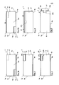
- FIG. 1a shows a sealing strip 1 according to the invention for sealing a joint 2 between a frame profile 3, for example, a window or door frame profile, and a wall 4, wherein the sealing region of the wall is usually the frame profile facing wall reveal 4a (see FIG. 6 ).
- the sealing strip 1 comprises a foam strip 6 which consists of an elastically compressible and resilient material, for example an open or closed-cell material.
- the foam strip 6 is resiliently retarded according to the embodiments of this invention, which area may extend only over one zone or the entire foam strip. This can generally be done so that the fully compressed foam strip will not go to its fully relaxed state until ⁇ 5 minutes or ⁇ 30 minutes after the compression force has been removed, but ⁇ 5-10 hours.
- a suitable impregnation for example a polymer dispersion such as an acrylate dispersion, latex dispersion or a wax, the average particle size is in the range of 1-10 microns.
- the foam strip may in this case be provided in regions or in whole (ie, preferably homogeneous) with such an impregnation.
- the sealing strip is in Fig. 1 in fully decompressed and deferred condition. Possibly.
- the impregnation 15 may also have a water vapor diffusion-braking effect.
- the sealing strip 1 has two opposite broad sides 1a, 1b, which in each case can be applied to the corresponding contact surfaces 3a, 4a of the frame profile 3 and wall 4. Transverse to these broad sides are narrow sides 1c, 1d of the sealing strip, which bridge the gap 2 and in the installed state of the sealing strip usually have a smaller width than the broadsides. In individual cases, however, the narrow sides may also have a greater width than the broad sides of the sealing strip (which may apply in the completely reset (decompressed) state of the sealing strip, in the installed state the ratio should be a maximum of 1: 1). This can generally apply in the context of the invention.
- the sealing strip 1 according to the invention further comprises an additional strip 7, which consists at least partially of a material with heavy fractions, by which the sound insulation of the joint seal and also independently of the handling of the sealing strip over conventional sealing strips are substantially improved.
- the additional strip 7 is formed in the sealing strip of the embodiments overlapping with the foam strip 6, which applies in particular in the installed state. This overlap can be seen in particular with regard to the extension of the sealing strip between the first and second broadside. When the sealing strip is arranged in the compressed state in the joint, the foam strip is thus at least partially compressed by the additional strip.
- the additional strip 7 is arranged in a channel or groove 6a of the foam strip 6, this groove being open toward the narrow side 1d (which, however, is not absolutely necessary), the additional strip 7 can also be arranged on the upper side of the foam strip 6.
- the additional strip 7 is attached to the foam strip, here by an adhesive layer 7a, for example, a self-adhesive layer.
- a suitable fastening means 8b is arranged on the broad side 1b, here in the form of an adhesive layer, in particular a self-adhesive layer.
- the adhesive layers can generally be covered within the scope of the invention with a peelable protective film (not shown).
- the sealing strip can be fastened or at least adhered to at least one or both of the bearing surfaces of the frame and wall, so that the sealing strip can be arranged securely in the joint and a proper and long-lasting assembly of the sealing strip is ensured despite the comparatively high weight of the additional strip.
- the additional strip consists according to the embodiment of a plastic material such as PVC with a mineral or metallic filler, in particular barium sulfate.
- the filler is distributed in the matrix of the additional strip, more precisely distributed homogeneously arranged.
- the additional strip has a specific gravity of about 2 g / cm 3 or at a thickness of about 3 mm, a basis weight of 6 kg / sqm, this has the additional strip a suitable proportion of heavy fillers, here barium sulfate in a proportion of about 30 to 40 wt .-% in the material of the additional strip.
- the additional strip further has according to the embodiment, a thickness of about 3 mm and a width of about 3 cm and has a rectangular cross section.
- the additional strip extends according to the example over a width of 25 to 50% of the width of the sealing strip, but this depends on the depth of the respective joint and thus the width of the sealing strip to be used.
- the additional strip has according to the embodiment, a weight per meter running of 150g.
- the additional strip has a share of about 50% of the total weight of the sealing strip, based on its installed state.
- the additional strip consists of a non-foamed, so solid material.
- the additional strip is independent of this from a little rigid material, whereby the sealing strip is rolled up in the longitudinal direction, in particular under compression of the foam material, and when rolling of the sealing strip, this due to the weight of the additional strip slightly on the contact surface, usually the contact surface of the frame profile, adapts (the provided with sealing strip frame can then be inserted on the wall or in the wall opening and fixed in this). Nevertheless, the bending stiffness of the additional strip is many times higher than that of the foam material of the sealing strip.
- the sealing strip 1 may comprise a further additional strip 9, which contains no heavy material fractions and, for example, is provided for producing an (additional) water vapor diffusion barrier or for other ticks.
- the further additional strip may also consist of a foam material, also from the material of the foam strip itself.
- FIG. 1b shows a modification of the embodiment according to FIG. 1a , wherein the fastening means 8b, preferably in the form of an adhesive layer, in particular in the form of a self-adhesive layer, is disposed on the broadside of the sealing strip facing away from the additional strip 7, ie the upper broad side in the figure.
- the fastening means 8b preferably in the form of an adhesive layer, in particular in the form of a self-adhesive layer, is disposed on the broadside of the sealing strip facing away from the additional strip 7, ie the upper broad side in the figure.
- this results in handling advantages, for example, if the additional strip is to be arranged on the side facing away from the frame profile.
- FIG. 2 shows a sealing strip accordingly FIG. 1 , wherein the modification consists in that the adhesive layer 18a, in particular self-adhesive layer, is additionally arranged on the broad side 1a with the additional strip 7.
- the adhesive layer 18a extends as shown only over the width of the additional strip 7, but may also extend laterally beyond.
- the adhesive layer or another fastening means for the corresponding contact surface can also be provided only on one broad side (the broad side 1a or 1b) or on both broad sides 1a, 1b.
- the adhesive layer 18a is only optional here.
- the fastening means may also extend (optionally only) over the additional strip at the corresponding broad side (as shown here, see adhesive layer 18a). Incidentally, the full content of the statements of FIG. 1 directed.
- FIG. 3 shows a modification of the sealing strip after FIG. 1 , wherein the modification is in a different profile design of the additional strip 27, for the rest, be full on the comments FIG. 1 directed.
- the additional strip 27 extends beyond its body 27a beyond the narrow side 1c, for which purpose the additional strip has a flank 27b arranged on the narrow side 1d.
- the additional strip is thereby formed substantially L-shaped.
- the additional strip thus extends over a greater part of the height of the sealing strip, especially in the installed state of the same, so that an improved sound insulation is given, and at the same time an increased water vapor diffusion resistance in the region of the additional strip, or with a corresponding arrangement of the sealing strip on the inside of the room the seal.
- the additional strip may be relatively flat.
- FIG. 4 shows a further modification of the additional strip 37 after FIG. 1 , moreover, the remarks to FIG. 1 is referenced.
- the additional strip 37 extends over the entire width of the sealing strip 1, resulting in a further improved sound insulation.
- the additional strip has a region 37b which projects toward the interior of the foam strip 6 and forms a cross-sectional narrowing of the foam strip 6, thereby further improving the sound insulation. If the projecting region 37b is arranged eccentrically, preferably in the region of a narrow side, this can at the same time serve to produce a water vapor diffusion gradient, so that the sealing strip is more diffusion-tight inside than in the installed state. It is understood that in this case the additional strip 37 does not have to extend over the entire width of the sealing strip, for example according to the FIGS. 1, 2 ,
- the adhesive layer 8a may extend over the entire width of the additional strip.
- FIG. 5 shows a further modification of the sealing strip 1 according to the invention, in which the additional strip 47 is secured by means of a profile strip 48 on the foam strip.
- the profile strip 48 may be suitably connected to the foam strip 6 in a form-fitting and / or cohesive manner, for example comprising an anchoring projection 48a, which protrudes into the foam strip, for example by engaging behind an undercut of the foam strip.
- the profile strip 48 may be glued to the foam strip 6.
- the additional strip 7 is attached by suitable means to the profile strip 48, for example, glued to this or fixed in a clamping seat on a mounting profile 48b thereof.
- In order to allow greater compression of the sealing tape in the installed state of the additional strip 47 and profile strip 48 may have a lower height.
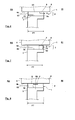
- FIGS. 6 to 8 show arrangements according to the invention sealing strip in the joint between the frame profile and wall starting from a sealing strip FIG. 1 , it goes without saying corresponding apply to the other sealing strip according to the invention, in particular the embodiments. It is further understood that these representations also apply to the arrangement of the sealing strip 1 on the frame profile, ie independent of the arrangement of the wall. This may apply, for example, when the sealing strip is preassembled on the frame profile in order to be inserted into the associated wall opening.
- the sealing strip extends at least substantially over the entire frame width FT, thus representing both a seal to the interior of the room RI and the space outside RA.
- the arrangement of further sealing means for sealing the gap is thereby unnecessary.
- the sealing strip may also have a smaller width with respect to the respective frame width, thus, for example, only a space inside and / or only a space outside seal results, optionally also with formation of a seal in the middle region of the joint, then below Use of other sealing agents.
- the sealing strip can in each case be adapted to the general requirements, for example for the outer space-side sealing by a suitable means 62 such as a film, a coating or impregnation reinforced water repellent or impact rainproof be formed.
- the sealing strip on the inside of the room may have an increased water vapor diffusion resistance with respect to the middle or space outside region of the sealing strip, for example by arranging the additional strip 7 but alternatively or additionally by other means, for example a diffusion-inhibiting impregnation, coating, etc.
- FIG. 6 shows an arrangement of a sealing strip 1 after Fig. 1 in a joint 2 between the frame profile 3 and wall 4, wherein the sealing strip is arranged compressed between the contact surfaces 3a, 4a of the frame profile and wall.
- the additional strip 7 serves to improve the sound insulation.
- the additional strip 7 is in this case arranged outside the room RA, RI indicates the room inside.
- the additional strip 7 abuts against the contact surface of the frame profile 3, optionally, the sealing strip may also be arranged in the joint, that the additional strip 7 of the wall 4 or soffit is facing.
- Another additional strip 9, which must contain no heavy matter shares but may contain here covers the foam strip 6, so that the area 6a of the foam strip 6 is more compressed at the level of the additional strip 9, as the adjoining this space outside area 6b of the foam strip, and thereby at the same time has a higher water vapor diffusion resistance than the region 6b and acts as a water vapor diffusion brake.
- the sealing strip can be fastened or adhered to the contact surface 3a of the frame profile and / or the abutment surface 4a of the wall with a fastening means, for example a suitable profiling or an adhesive layer, in particular self-adhesive layer, and possibly abut the respective abutment surface except for the fastening means.
- FIG. 7 shows an alternative arrangement of the sealing strip FIG. 6
- the additional strip according to the invention comprising heavy-material fractions is arranged on the outside of the space, here facing the frame profile 3 (although in certain cases an orientation towards the wall may also be present).
- An attachment of the sealing strip relative to the frame profile 3 can also be done here by suitable fastening means, as described.
- the sealing strip can also be connected here in particular with the contact surface of the wall by a self-adhesive layer.
- the self-adhesive layer on the broad side 1a (facing the frame profile) may extend over the additional strip, possibly only over this.
- the additional strip 7 here covers the foam strip 6, so that the area of the foam strip 6a at the level of the additional strip 7 is more compressed than the adjoining space outside area 6b, and thereby at the same time has a higher water vapor diffusion resistance and acts as a water vapor diffusion brake. At the same time, the additional strip 7 serves the sound insulation.
- a vapor diffusion brake or barrier 71 may be provided on the inner narrow side 1c, for example by means of a suitable foil, impregnation or coating.
- FIG. 8 shows a further modification of the sealing strip according to the invention, wherein the additional strip 7 is arranged in the central region of the foam strip 6.
- the additional strip 7 is here arranged centrally on the foam strip.
- the additional strip for generating a water vapor diffusion gradient is displaced off-center with respect to the center plane 82 of the sealing strip, in particular towards the interior side, so that the sealing strip in the assembled state is denser inside than in relation to a vapor diffusion resistance.
Landscapes
- Engineering & Computer Science (AREA)
- Civil Engineering (AREA)
- Structural Engineering (AREA)
- Building Environments (AREA)
Abstract
Description
- Dichtstreifen zur Abdichtung einer Fuge zwischen einem Rahmenprofil, etwa Fensterrahmenprofil, und einer Wand, mit einem komprimierbaren und rückstellfähigen, vorzugsweise verzögert rückstellfähigen, Schaumstoffstreifen, wobei der Dichtstreifen zwei gegenüberliegende Breitseiten aufweist, welche jeweils an eine Anlagefläche von Rahmen und Wand anlegbar sind, und zwei gegenüberliegende, sich quer zu den Breitseiten erstreckende Schmalseiten.
- Gattungsgemäße Dichtstreifen können rauminnen- oder raumaußenseitig an der Fuge angeordnet sein, um die Außenabdichtung der Fuge zu ergeben, wobei der Dichtstreifen dann gegebenenfalls zusammen mit anderen Dichtungsmitteln wie z.B. einem Polymerschaum (Ortschaum) eingesetzt werden kann. Andererseits sind gattungsgemäße Dichtstreifen bekannt, welche sich zumindest im Wesentlichen über die gesamte Rahmenbreite erstrecken können, also sowohl eine raumaußenseitige als auch eine rauminnenseitige Abdichtung der Fuge ausbilden. Derartige Dichtstreifen müssen je nach Anwendung vielfältige Anforderungen erfüllen, beispielsweise in Hinblick auf die zu erzielende Wärmedämmung, Luftdichtheit, Schlagregendichtheit, Wasserdampfdiffusionseigenschaften und dergleichen.
- Andererseits werden in Bezug auf die Ausbildung von Gebäudehüllen weitergehende Anforderungen gestellt, so beispielsweise auch in Bezug auf eine verbesserte Schalldämmung. Hierzu wurden bei Fenstern und Türen zum Teil erhebliche Anstrengungen gemacht, beispielsweise durch Dreifachverglasung, spezielle Rahmenprofile u. dgl. Es hat sich jedoch herausgestellt, dass insbesondere bei vergleichsweise breiten Fugen auch eine Verbesserung der Fugenabdichtung in Bezug auf erhöhte Schalldämmung wünschenswert ist, da die Fugenabdichtungen insoweit eine Schwachstelle bei dem Aufbau einer schalldämmenden Gebäudehülle darstellt. Dies gilt insbesondere bei hohen Geräuschpegeln.
- Weiterhin besteht das Bedürfnis, die Handhabung der Dichtstreifen beim Anbringen an einem Rahmenprofil oder beim Einbringen in die Fuge zwischen Rahmenprofil und Wand zu verbessern. Dies gilt insbesondere dann, wenn der Dichtstreifen in einer Form konfektioniert vorliegt, beispielsweise als Rolle, welche sich von der Einbaugestalt des Dichtstreifens in der Fuge bzw. an dem Rahmenprofil unterscheidet. Dies gilt insbesondere dann, wenn der Dichtstreifen zur verzögerten Rückstellung imprägniert ist. Ist der Dichtstreifen von seinem Bevorratungszustand ausgehend zu deformieren, um an dem Rahmenprofil befestigt bzw. in die abzudichtende Fuge eingebracht zu werden, beispielsweise von einer Rolle abzurollen, so wird der Dichtstreifen nur mit gewisser zeitlicher Verzögerung in seine Sollgestalt überführt, beispielsweise in einen gestreckten, geradlinigen Zustand. Hierdurch kann die Befestigung des Dichtstreifens an dem Rahmenprofil oder dessen Einbringung in die Fuge zeitlich verzögert werden bzw. es ergibt sich leichter die Gefahr einer fehlerhaften Befestigung des Dichtstreifens an dem Rahmenprofil, beispielsweise dass der Dichtstreifen nicht exakt in seiner Sollposition sondern aus dieser verrückt an dem Rahmenprofil befestigt wird, oder Zwickel bzw. Taschen mit unsachgemäßer Befestigung und Anlage der Unterseite des Dichtstreifens an dem Rahmenprofil verbleiben, insbesondere bei Befestigung mittels einer Selbstklebeschicht. Dies kann dann auch zu einer Beeinträchtigung der Luft- und Wasserdichtheit der Fugenabdichtung führen.
- Der Erfindung liegt die Aufgabe zugrunde, einen Dichtstreifen zur Abdichtung einer Fuge zwischen einem Rahmenprofil und einer Wand bereitzustellen, welcher eines oder mehrere der oben genannten Probleme löst.
- Die Erfindung wird durch einen Dichtstreifen nach Anspruch 1 gelöst, bei welchem der Dichtstreifen einen sich zumindest über einen Teil dessen Breite erstreckenden Zusatzstreifen aufweist, welcher zumindest teilweise aus einem Material mit Schwerstoffanteilen besteht. Vorzugsweise erstreckt sich hierbei der Zusatzstreifen in Längsrichtung des Dichtstreifens, was allgemein im Rahmen der Erfindung gelten kann. Hierdurch kann zum einen die Schalldämmung des Dichtstreifens, welcher einen Schaumstoffstreifen mit relativ schlechten Schalldämmungseigenschaften umfasst, deutlich verbessert werden, insbesondere, da das mit Schwerstoffanteilen versehene Material des Zusatzstreifens sowie gegebenenfalls bei Verbindung von Schaumstoffstreifen und Zusatzstreifen, z.B. durch Verklebung, die angrenzenden Bereiche des Schaumstoffstreifens, nur erschwert durch den Schall in Schwingungen versetzt werden.
- Zwar ist es bereits bekannt, Dichtstreifen mit sich in dessen Längsrichtung erstreckenden Zusatzstreifen zu versehen, beispielsweise aus der
EP 1 811 111 A1 . Hier dient jedoch der Zusatzstreifen nur dazu, an dem gegebenen Querschnittsbereich des Dichtstreifens einen erhöhten Wasserdampfdiffusionswiderstand desselben auszubilden, so dass der Wasserdampfdiffusionswiderstand rauminnenseitig größer ist als raumaußenseitig. Weiterhin besteht hier der Zusatzstreifen auch nur aus dem Material des Schaumstoffstreifens selber oder aus einem einfachen Kunststoffmaterial, wodurch die der Erfindung zugrundeliegende Aufgabe nicht zufriedenstellend gelöst werden kann. - Zugleich und unabhängig von dem oben Gesagten hat es sich herausgestellt, dass der erfindungsgemäße Dichtstreifen aufgrund der Ausbildung des Zusatzstreifens mit Schwerstoffanteilen einfacher handhabbar ist. Dies gilt insbesondere dann, wenn der Dichtstreifen in einer Form konfektioniert vorliegt, beispielsweise als Rolle, welche sich von der Einbaulage des Dichtstreifens in der Fuge bzw. der Gestalt des Dichtstreifens an dem Rahmenprofil unterscheidet, wobei ein derart vorkonfektionierter Dichtstreifen von der Erfindung mit umfasst ist. Es hat sich im Zuge der Erfindung herausgestellt, dass der erfindungsgemäße Dichtstreifen mit Schwerstoffanteilen in dem Zusatzstreifen, insbesondere wenn dieser zur verzögerten Rückstellung imprägniert oder sonst wie behandelt ist, schneller in seine ursprüngliche Gestalt, die dieser vor der Überführung in die Bevorratungsgestalt hatte, zurückkehrt, insbesondere in eine gestreckte, geradlinige Gestalt. Der erfindungsgemäße Dichtstreifen ist hierdurch beim Abrollen und geradlinigem Ausrichten leichter manuell handhabbar. Der Dichtstreifen, der zumindest im Wesentlichen aus einem Schaumstoff besteht, legt aufgrund der Schwerstoffanteile leichter "von selbst" leichter flach, als ohne Zusatzstreifen mit Schwerstoffanteilen. Dies wird jeweils auf das erhöhte Gewicht des Zusatzstreifens zurückgeführt, welcher sozusagen den Dichtstreifen insgesamt unter Schwerkrafteinwirkung niederdrückt. Der derart flachgelegte Dichtstreifen kann dann manuell einfacher gehandhabt und exakter an seiner Befestigungsfläche festgelegt werden, beispielsweise an dieser verklebt werden. Gegebenenfalls entstehenden Zwickel oder taschenförmige Einbuchtungen an den Breitseiten des Dichtstreifens, welche zu Verbindungs- und damit Abdichtfehlern führen würden, können leichter vermieden werden. Der Dichtstreifen wird somit durch das erhöhte Gewicht des Dichtstreifens schneller in seine Sollgestalt überführt, wodurch der Dichtstreifen leichter handhabbar und die entsprechende Abdichtung sicherer durchführbar ist.
- Weiterhin ist der erfindungsgemäße Dichtstreifen einfach herstellbar, da lediglich der Zusatzstreifens an dem Schaumstoffstreifen anzubringen ist. Hierbei kann der Zusatzstreifen an der Oberseite des Schaumstoffstreifens befestigt werden, beispielsweise verklebt werden, ggf. kann der Zusatzstreifen auch mit einem Teil oder seiner gesamten Höhe in den Schaumstoffstreifen eingesetzt werden. Hierzu kann der Schaumstoffstreifen mit einer rinnenförmigen Vertiefung oder Nut versehen sein, welche ggf. zu einer Schmalseite des Dichtstreifens hin offen ausgebildet sein kann.
- Die Matrix des Zusatzstreifens kann aus einem Kunststoffmaterial bestehen, beispielsweise aus einem Polyolefin wie Polyäthylen, Polypropylen usw., PVC (Polyvinylchlorid) o.dgl. Die Schwerstoffanteile können verteilt, vorzugsweise gleichmäßig verteilt, in der Matrix des Zusatzstreifens angeordnet sein, ggf. können jedoch auch Zonen oder Teilbereich erhöhter und verringerter Anteile an Schwerstoffe vorliegen (ggf. in Teilbereichen auch ohne Schwerstoffanteile). Die Schwerstoffanteile können partikelförmig in der Matrix des Zusatzstreifens vorliegen und in dieser verteilt angeordnet sein. Ggf. können die Schwertstoffanteile jedoch auch als Schicht oder zusammenhängenden Bereich des Zusatzstreifens ausgebildet sein.
- Zweckmäßigerweise weist das Material des Zusatzstreifens mit Schwerstoffanteilen eine spezifische Dichte von ≥ 1,4 g/cm3, vorzugsweise eine spezifische Dichte von ≥ 1,45 bis 1,55 g/cm3. In Bezug auf die Schalldämmung und/oder die beschriebenen Handhabungsvorteile ist es besonders vorteilhaft, dass das Zusatzstreifenmaterial eine spezifische Dichte von ≥ 1,65-1,75 g/cm3 aufweist, ggf. auch ≥ 1,85 g/cm3oder ≥ 2 g/cm3. Eine bestimmte Obergrenze der spezifischen Dichte des Zusatzstreifensmaterials ist nicht gegeben, der Zusatzstreifen insgesamt sollte jedoch ein Gewicht aufweisen, welches von dem Schaumstoffmaterial des Dichtstreifens getragen werden kann, also der Zusatzstreifen ohne äußere Einwirkungen nicht in das Schaumstoffmaterial einsinkt. Andererseits kann dem im Einbauzustand des Dichtstreifens entgegengewirkt werden, wenn der Zusatzstreifen mit Befestigungsmitteln an der korrespondierenden Anlagefläche von Rahmenprofil oder Mauerwerkslaibung befestigbar ist, beispielsweise durch einen Selbstklebestreifen. Dies ist allgemein im Rahmen der Erfindung bevorzugt, um auch im Bereich des Zusatzstreifens eine Haftung mit der Anlagefläche zu ergeben. Aus praktischen Gründen kann die spezifische Dichte des Zusatzstreifenmaterials ≤ 3,5-4 g/cm3 oder 3,0-3,25 g/cm3 aufweisen, gegebenenfalls auch ≤ 2,5-2,75 g/cm3. Eine spezifische Dichte im Bereich von ca. ≤ 3,5-4 g/cm3 hat sich für viele Anwendungsfälle als besonders zweckmäßig erwiesen.
- Das Schwerstoffmaterial des Zusatzstreifens kann eine spezifische Dichte von ≥ 2-2,25 g/cm3 aufweisen, beispielsweise von ≥ 2,5-2,70 g/cm3, vorzugsweise von ≥ 3,0-3,5 g/cm3 oder besonders bevorzugt von ≥ 3,75-4 g/cm3. Die spezifische Dichte des Schwerstoffmaterials kann ≤ 6-8 g/cm3 oder ≤ 5,5 g/cm3 betragen. Die angegebene spezifische Dichte des Schwerstoffmaterials bezieht sich hierbei jeweils auf die Bulk-Dichte, also die des homogenen Festkörpermaterials. Schwerstoffmaterialien mit möglichst hoher spezifischer Dichte sind bevorzugt, da hierdurch ggf. ein geringerer Anteil desselben in dem Zusatzstreifenmaterial vorgesehen und letzteres hierdurch flexibler an andere Anforderungen, beispielsweise im Hinblick auf seine Biegeelastizität, angepasst werden kann. Als Schwerstoffmaterialien können beispielsweise mineralische und/oder metallische Füllstoffe eingesetzt werden, beispielsweise auch Silikate oder Siliziumdioxid (vorzugsweise wasserfrei, beispielsweise als Quarz), Metalloxide wie Titandioxid, Eisenoxide o. dgl. Als besonders bevorzugt haben sich Erdalkalisalze wie Carbonate, Phosphate oder Sulfate herausgestellt, insbesondere Sulfate. Als besonders vorteilhaft haben sich auch gemischte Erdalkaliverbindungen, z.B. enthaltend andere Metallionen wie gemischte Erdalkalimetalle wie Calcium-Barium-Verbindungen, Erdalkali-Übergangsmetall-Verbindungen o. dgl. erwiesen, wobei die gemischten Erdalkalimetallverbindungen, insbesondere Erdalkalimetall-Übergangsmetallverbindungen auch gemischte Oxide darstellen können, beispielsweise Bariumtitanat, Bariumferrate und dergleichen. Die Erdalkalimetallverbindungen, insbesondere gemischten Erdalkalimetallverbindungen, können andere Anionen enthalten, wie gemischte Carbonat-Phosphate, Phosphat-Sulfate, Carbonat-Sulfate oder dergleichen, insbesondere des Calciums und/oder Bariums. Sulfate haben sich als besonders bevorzugt herausgestellt, da diese chemisch inert sind (beispielsweise auch gegenüber Wasser bei saurem pH-Wert). Als besonders bevorzugt haben sich einzeln oder in Kombination Calciumcarbonat, Bariumcarbonat, Calciumsulfat und Bariumsulfat herausgestellt, insbesondere Bariumcarbonat und/ oder Bariumsulfat, ganz besonders Bariumsulfat.
- Das Schwerstoffmaterial kann in einem Gehalt von 5-95 Gew.-% in dem Zusatzstreifenmaterial vorliegen, beispielsweise im Bereich von 10-90 Gew.-%, vorzugsweise im Bereich von 20-80 Gew.-% oder 30-70 Gew.-%.
- Das Zusatzmaterial kann ein Flächengewicht von ≥ 2-2,5 kg/m2, vorzugsweise ≥ 3-4 kg/m2, besonders bevorzugt im Bereich von 4,5-8 kg/m2 aufweisen. Das Flächengewicht kann ≤ 9-10 kg/m2 betragen, ohne hierauf beschränkt zu sein. Dies kann gegebenenfalls gelten für eine Dicke des Zusatzmaterials von 3 mm, aber auch unabhängig hiervon. Ein derartiges Material hat sich in Hinblick auf die Erfüllung der Schalldämmung und der beschriebenen Handhabungsvorteile, jeweils getrennt und in Kombination, als vorteilhaft bzw. besonders vorteilhaft erwiesen, da dies einerseits eine hohe Beschwerung des Dichtstreifens ermöglicht, andererseits noch ausreichend flexibel ist und andererseits nicht mit zu hohem Aufwand wie z.B. mittels einer Selbstklebeschicht oder Klemmverbindungen an der Anlagefläche wie dem Rahmenprofil befestigbar ist. Überraschenderweise kann dieses Material das gestellte komplexe Anforderungsprofil erfüllen.
- Der Zusatzstreifen kann an dem Dichtstreifen dauerhaft oder lösbar befestigt sein, beispielsweise stoff-, form- und/oder kraftschlüssig. Die Befestigung kann nach einer bevorzugten Variante durch eine Klebeschicht, z. B. eine dauerhafte Klebeschicht oder durch eine Selbstklebeschicht erfolgen. Die Verbindung kann auch form- und/oder kraftschlüssig erfolgen, wozu der Dichtstreifen und/oder der Zusatzstreifen Hinterschneidungen aufweisen können, welche von dem jeweils anderen Bauteil hintergriffen werden. Ggf. kann der Zusatzstreifen auch durch ein Verbindungsmittel wie ein Verbindungsprofil an dem Dichtstreifen befestigt sein. Das Verbindungsprofil kann form-, kraft- und/oder stoffschlüssig mit einem der beiden Elemente von Zusatzstreifen und Dichtstreifen oder mit beiden verbunden sein, insbesondere mit dem Zusatzstreifen. Ggf. kann der Zusatzstreifen auch lediglich lose an dem Dichtstreifen anliegen.
- Der Zusatzstreifen kann eine Dicke bzw. Höhe von ≥ 0,25 mm oder ≥ 0,5-1 mm aufweisen, vorzugsweise eine Dicke von ≥ 1,5-2 mm oder auch ≥ 3-5 mm. Es versteht sich, dass die Höhe bzw. Dicke des Zusatzstreifens an die jeweiligen Erfordernisse in Bezug auf Schalldämmung und/oder dessen Handhabung oder anderer Eigenschaften wie den Wasserdampfdiffusionswiderstand durch den Dichtstreifen optimiert werden kann, da das Material des Zusatzstreifens zumeist einen höheren Wasserdampfdiffusionswiderstand aufweist als das Schaumstoffmaterial des Dichtstreifens. Die Dicke des Zusatzstreifens ist nicht beschränkt, vorzugsweise weist dieser jedoch eine Dicke ≤ 8-10 mm oder 4-6 mm auf, so dass er einerseits ausreichend Gewicht und andererseits ausreichend Flexibilität aufweist.
- Der Zusatzstreifen kann eine Breite von ≥ 3-5 mm oder ≥ 7 mm, vorzugsweise von ≥ 10-15 mm aufweisen, beispielsweise ≥ 20-30 mm. Der Zusatzstreifen kann sich ggf. auch über die gesamte Breite des Dichtstreifens erstrecken, vorzugsweise erstreckt sich der Zusatzstreifen jedoch nur über einen Teil der Breite des Dichtstreifens, beispielsweise ≤ 50-75 % desselben oder ≤ 30-40 % der Breite des Dichtstreifens, so dass der Zusatzstreifen, wenn dieser überdeckend zu dem Schaumstoffstreifen angeordnet ist, zugleich als Wasserdampfdiffusionsbremsmittel im Sinne der
EP 1 811 111 A1 wirken kann. Der Zusatzstreifen kann sich über ≥ 5-10 % der Breite des Dichtstreifens erstrecken, vorzugsweise über ≥ 20-25 % oder ggf. auch oder ≥ 33 % der Breite des Dichtstreifens. Hierdurch kann der Zusatzstreifen ausreichend Gewicht aufweisen, um vorteilhaft in Bezug auf Schalldämmung und/oder Handhabung ausgebildet zu sein. - Der Zusatzstreifen kann ein Gewicht je laufendem Meter von ≥ 10-20 g, vorzugsweise ≥ 30-50 g, besonders bevorzugt ≥ 75 -100 g aufweisen, damit der Dichtstreifen ausreichend beschwert ist, insbesondere bei schmalen Dichtstreifen jedoch gegebenenfalls auch weniger. Der Zusatzstreifen kann eine Gewicht je laufendem Meter von ≥ 200-300 g, vorzugsweise ≤ 400-450g oder ≤ 500g, insbesondere bei breiten Dichtstreifen gegebenenfalls auch mehr, so zu hohe Gewichte des Dichtstreifens, welche dessen Handhabung erschweren würden, vermieden werden.
- Der Zusatzstreifen kann einen Anteil von ≥ 10-20%, vorzugsweise 30-50%, besonders bevorzugt ≥ 60-75% oder ≥ 80% am Gesamtgewicht des Dichtstreifens haben. Der Zusatzstreifen kann einen Anteil von ≤ 95-98% oder ≤ 85-90% am Gesamtgewicht des Dichtstreifens haben, vorzugsweise ≤ 70-80% oder ≤ 50-60%. Das Gesamtgewicht bezieht sich auf den Dichtstreifen in Einbauzustand, also z.B. ohne Berücksichtigung einer zu entfernenden Abdeckung einer Klebeschicht oder dergleichen, aber mit Selbstklebeschicht, falls vorhanden.
- Gegebenenfalls kann der Schwerstoffe enthaltende Zusatzstreifen selber, beispielsweise durch geeignete Profilierung, mit integrierten, einstückig angeformten Mitteln zur Festlegung an dem Rahmenprofil ausgerüstet sein (diese Mittel sind also verschieden von einer etwaig vorhandenen Klebeschicht/Selbstklebeschicht). Diese Profilierung kann beispielsweise in Form von Nuten, Vorsprüngen oder dergleichen ausgeführt sein. Der Zusatzstreifen kann gegebenenfalls auch frei von derartigen integrierten, einstückig angeformten Mitteln zur Festlegung an dem Rahmenprofil sein.
- Der Dichtstreifen kann eine Breite von ≥ 1-2 cm, vorzugsweise ≥ 3-5 cm aufweisen, z.B. bis zu 10 cm oder gegebenenfalls bis zu 15 cm oder bis zu 20 cm oder auch mehr, um an die Tiefen der abzudichtenden Fugen angepasst zu sein.
- Der Schaumstoffstreifen und der Zusatzstreifen können verschiedene Querschnittsprofile aufweisen, beispielsweise unabhängig voneinander einen im wesentlichen rechteckigen Querschnitt, aber auch jeweils unabhängig voneinander eine profilierte obere und/oder untere Breitseite, wobei vorzugsweise nur eine der Breitseiten profiliert ist. Die Profilierung kann hierbei Bereiche unterschiedlicher Profilhöhen ausbilden, welche stufenförmig oder mit kontinuierlichen Bereichen ineinander übergehen können. Der Zusatzstreifen kann einen Bereich aufweisen, welcher den Schaumstoffstreifen zumindest teilweise an einer Schmalseite mit einem Bereich zusätzlich abdeckt, wobei sich dieser Bereich von dem Korpus des Zusatzstreifens aus in Form eines Vorsprunges oder eines Profilbereichs erstrecken kann. Der Zusatzstreifen kann auch einen Bereich aufweisen, welcher sich über dessen Korpus hinausgehend in das Schaumstoffmaterial erstreckt und eine Querschnittsverengung des Schaumstoffmaterials ausgebildet. Hierdurch kann eine zusätzliche sichere Schallbarriere geschaffen werden. Der Zusatzstreifen kann im einfachsten Fall in Art einer Leiste ausgeführt sein.
- Der Zusatzstreifen kann an beiden Breitseiten, welche parallel zu den Breitseiten des Dichtstreifens bzw. der Hauptebene des Dichtstreifens verlaufen, eben ausgebildet sein. Ggf. kann der Zusatzstreifen auch an zumindest einer Breitseite profiliert sein, insbesondre auch der dem Schaumstoffstreifen zugewandten Breitseite. Hierdurch können im Einbauzustand des Dichtstreifens auch Bereiche unterschiedlicher Kompression oder Materialanhäufung und damit auch unterschiedlichen Wasserdampfdiffusionswiderstandes in dem Schaumstoffstreifen erzeugt werden.
- Der Dichtstreifen mit Zusatzstreifen kann verbiegbar ausgeführt sein, insbesondere derart, dass der Dichtstreifen als Rolle konfektionierbar oder konfektioniert ist, wobei der Dichtstreifen in seiner Längsrichtung aufgerollt sein kann. Das Material des Zusatzstreifens kann eine nur geringe oder gegebenenfalls praktisch keine Biegesteifigkeit aufweisen. Die Biegesteifigkeit des Materials kann derart sein, dass das Material skaliert auf eine Breite von 3 cm und eine Dicke von 3 mm bei einer Länge von 10 cm an einem Ende horizontal eingespannt (nur) unter Schwerkrafteinwirkung am gegenüberliegenden Ende um ≥ 0,5-1 cm absinkt, vorzugsweise ≥ 2-3 cm oder besonders bevorzugt ≥ 4-5 cm, und zwar gegenüber dem eingespannten Ende. Die Länge von 10 m bezieht sich die frei von der Einspannung vorstehende Streifenlänge. Die Biegesteifigkeit unter diesen Bedingungen kann derart sein, dass das freie Ende um nicht mehr als 9-9,5 cm oder vorzugsweise nicht mehr als 7-8 cm absinkt. Das Material weist hierbei einen rechteckigen Querschnitt auf, mit der Breitenerstreckung horizontal ausgerichtet. Ein derartiges Material hat sich in Hinblick auf die Erfüllung der Schalldämmung und der beschriebenen Handhabungsvorteile, jeweils getrennt und in Kombination, als vorteilhaft bzw. besonders vorteilhaft erwiesen. Einerseits hat das Material also eine gewisse Rückstellelastizität, andererseits ist es mit nur geringen Kräften verbiegbar und damit fertigungstechnisch einfach aufrollbar. Anderseits werden aber beim Abrollen keine elastischen Biegekräfte freigesetzt, was sich für die Handhabung als wesentliche Erleichterung herausgestellt hat, da hierdurch der Dichtstreifen ohne störende Einflüsse sehr genau an der zugeordneten Anlagefläche, z.B. dem Rahmenprofil, positionierbar ist. Es versteht sich, dass hiermit die intrinsischen Materialeigenschaften beschrieben werden, unabhängig von der Querschnittsgestalt des jeweiligen Zusatzstreifens.
- Zusätzlich zu dem zumindest einen Zusatzstreifen enthaltenen Schwerstoffanteile können mindestens einer oder mehrere weitere Zusatzstreifen, vorzugsweise aus Kunststoffmaterial, vorgesehen sein, welche geringere oder keine Schwerstoffanteile enthalten. Dieser weitere Zusatzstreifen kann beispielsweise ausgebildet sein, um das Profil des Wasserdampdiffusionswiderstandes über die Breitenerstreckung des Dichtstreifens einzustellen, ggf. unabhängig von der Anordnung des Zusatzstreifens enthaltend Schwerstoffanteile. Natürlich können unterschiedliche Bereiche des Dichtstreifens im Hinblick auf ihre Schalldämmung einerseits und ihren Wasserdampfdiffusionswiderstand oder ihre Wärmedämmung andererseits unabhängig voneinander optimiert werden.
- Das Material des Zusatzstreifens weist vorzugsweise eine geringere Porosität (Gesamtporenvolumen) und/oder höhere Biegesteifigkeit auf, als das Schaumstoffmaterial des Dichtstreifens. Die Porosität des Materials des Zusatzstreifens kann kleiner/gleich der 2-5 fachen oder vorzugsweise kleiner/gleich der 10-25 fachen oder kleiner/gleich der 50-100 fachen Porosität des Schaumstoffmaterials des Dichtstreifens sein. Die Biegesteifigkeit des Zusatzstreifens kann größer/gleich der 2-5 fachen oder vorzugsweise größer/gleich der 10-25 fachen oder besonders bevorzugt größer/gleich der 50-100 fachen Biegesteifigkeit des Schaumstoffmaterials des Dichtstreifens sein. Das Matrixmaterial des Zusatzstreifens kann insbesondere ein ungeschäumtes Kunststoffmaterial sein, wodurch dieses, welches Schwerstoffanteile enthält, einfach herstellbar ist, beispielsweise durch ein Extrusionsverfahren. Das Material des Zusatzstreifens kann unter Anwendungsbedingungen, also bezogen auf den Einbauzustand, im wesentlich inkompressibel sein.
- Der Dichtstreifen bzw. das Schaumstoffmaterial desselben ist vorzugsweise elastisch rückstellfähig ausgeführt. Das Schaumstoffmaterial kann geschlossen- oder offenzellig oder gemischt geschlossen- und offenzellig ausgebildet sein. Das Schaumstoffmaterial kann an einer Schmalseite (und/oder einen Volumenbereich, welcher sich vorzugsweise an eine Schmalseite anschließt), imprägniert sein. Durch die Imprägnierung können eine oder mehrere der Eigenschaften wie der Wasserdampfdiffusionswiderstand, die Wasser- und/oder Luftdichtigkeit und/oder die Rückstelleigenschaften des Schaumstoffmaterials nach einer Kompression desselben eingestellt sein. Insbesondere kann der Dichtstreifen bzw. das Schaumstoffmaterial desselben zur verzögerten Rückstellung imprägniert sein, so dass der Dichtstreifen sich aus seinem komprimierten Zustand verzögert zurückstellend ausgerüstet ist, wie dies vorbekannt ist. Hierzu können an sich bekannte Kunststoffharze, Polymerpartikel, insbesondere organische Polymerpartikel, oder Wachse wie z.B. Polywachse oder Mikrowachse, einschließlich chlorhaltige Wachse und Paraffine, Bitumen oder bituminöse Produkte, eingesetzt werden. Die Imprägniermittel können insbesondere in Form von Dispersionen eingesetzt werden, insbesondere in Form von wässrigen Dispersionen, wie z.B. Acrylatdispersionen, Dispersionen von Poletherglykolen, Latex-Dispersionen (mit natürlichen und/oder synthetischen Kautschuken), Polychloropren, Butadien-Styrol-Polymere usw., oder Dispersionen der Wachse, oder in Form anderer vorzugsweise wässriger Beschichtungszusammensetzungen, insbesondere enthaltend organische Polymere, ohne hierauf beschränkt zu sein. Die vorzugsweise wässrigen Beschichtungszusammensetzungen können auch organische Verbindungen, beispielsweise Monomere und/oder Oligomere der oben genannten Verbindungen, in gelöster Form als "Klebemittel" enthalten, gegebenenfalls auch Kombination mit den oben beschriebenen dispergierten Partikeln. Der mittlere Polymerisationsgrad der Imprägnatpartikel kann ≥ 50-100 oder ≥ 200-300 oder vorzugsweise ≥ 500 Monomeren betragen, vorzugsweise ≤ 500.000 Monomeren oder vorzugsweise ≤ 100.000 Monomeren, vorzugsweise im Bereich von 1000 bis 25.000 Monomeren liegen, ohne hierauf beschränkt zu sein. Die dispergierten Imprägnatpartikel können einen für die Imprägnierung geeigneten Durchmessern aufweisen, insbesondere mittlere Durchmessern von ≤ 0,075-0,1 mm oder ≤ 0,2 mm, vorzugsweise mittleren Durchmessern von ≥ 0,01-0,05 oder ≥ 0,1-0,25 Mikrometer oder ≤ 0,5-1 Mikrometer, beispielsweise im Bereich von 1-10 Mikrometer, aber auch im Nanometerbereich. Die Viskosität des Imprägnats kann ≤ 300-500 mPas betragen. Das Imprägniermittel kann die Steifigkeit der Zellwände erhöhen, wie z.B. bei Wachsen. Vorzugsweise weist das Imprägniermittel eine ausreichende Klebrigkeit auf, um die Rückstellung zu verzögern, wobei die Klebekraft durch die elastischen Rückstellkräfte des komprimierten Schaumstoffes überwunden werden können. Die Imprägnierung kann beispielsweise in einem Tauchbad mit dem Imprägniermittel erfolgen, mit Walzen und Entspannen im Tauchbad und nachfolgendem Trocken. Die Imprägnierung zur verzögerten Rückstellung kann derart erfolgen, dass das Schaumstoffmaterial homogen getränkt ist, und also eine gleichmäßige Rückstellung über den Querschnitt des Dichtstreifens erfolgt. Alternativ können unterschiedliche Bereiche des Schaumstoffmaterials verschieden stark imprägniert sein, wobei manche Bereiche des Schaumstoffmaterials weniger stark oder nicht zur verzögerten Rückstellung imprägniert sind. Die stärker imprägnierten Bereiche können im mittleren Bereich oder an den Randbereichen des Dichtstreifens angeordnet sein. Die Imprägnierung zur verzögerten Rückstellung kann derart erfolgen, dass nach maximaler Kompression die vollständige Rückstellung erst nach ≥ 0,25-0,5 Stunden, ≥ 1-2 Stunden oder ≥ 5-10 Sunden erfolgt, vorzugsweise ≤ 48 -72 Stunden oder ≤ 24 Stunden oder maximal nach einer Zeit wie sie der vollständigen Tränkung (maximale Imprägnataufnahme) des Schaumstoffmaterials entspricht. Diese Angaben beziehen sich jeweils auf 20°C und 50% relative Luftfeuchtigkeit. Das Imprägnat kann wie üblich weitere Komponenten wie Flammschutzkomponenten enthalten.
- Allgemein kann der Dichtstreifen in seiner Einbausituation gegenüber dem vollständig dekomprimierten Zustand auf eine Dicke von 7-40% der Dicke im dekomprimierten Zustand komprimiert sein bzw. komprimierbar sein, vorzugsweise auf eine Dicke im Bereich von 10-30% oder 10-20%, insbesondere ca. 15%.Der erfindungsgemäße Dichtstreifen kann rauminnenseitig und/ oder raumaußenseitig in der abzudichtenden Fuge eingebracht sein bzw. für eine derartige Einbringung hergerichtet sein, beispielsweise eine hierfür geeignete Breite aufweisen. Ggf. kann der Dichtstreifen auch im mittleren Bereich einer Fuge eingesetzt sein, beispielsweise um eine Wärmedämmung auszubilden. Es versteht sich, dass der Dichtstreifen dann mit anderen Fugendichtungsmaterialien einzusetzen ist. Vorzugsweise erstreckt sich der Dichtstreifen sowohl rauminnenseitig als auch im mittleren Bereich der Fuge, ggf. vorzugsweise raumaußenseitig sowie über den mittleren Bereich der Fuge. Besonders bevorzugt erstreckt sich der Dichtstreifen über zumindest annährend die gesamte Rahmenbreite, so dass der Dichtstreifen die Fuge gleichzeitig rauminnenseitig und raumaußenseitig abdichten kann (es versteht sich, dass dann die Dichtstreifenbreite geringfügig kleiner als die Rahmenbreite sein kann, bspw. beidseitig jeweils um ≤ 5-10 mm oder ≤ 2-3 mm weniger breit, um ein "auspilzen" des Dichtbandes zu Vermeiden).
- Besonders bevorzugt ist der Zusatzstreifen mit Schwerstoffanteilen auf Höhe des Schaumstoffstreifens angeordnet, so dass der Zusatzstreifen im Einbauzustand des Dichtstreifens zumindest einen Teilbereich oder nur einen Teilbereich des Schaumstoffstreifens (jeweils in Bezug auf dessen Breitenerstreckung gesehen) überdeckt und somit komprimiert. Vorzugsweise ist der Zusatzstreifen derart an dem Dichtstreifen angeordnet und ausgebildet, dass dieser einen Schaumstoffstreifenbereich (insbesondere eine Schmalseite) stärker komprimiert, als ein angrenzender Schaumstoffstreifenbereich komprimiert ist, was für den Einbauzustand des Dichtstreifens gilt. Hierdurch kann der Zusatzstreifen zugleich als Wasserdampfdiffusionbremsmittel fungieren, entsprechend einem Zusatzstreifen nach der
EP 1 801 111 A1 . Der Dichtstreifen kann jedoch auch weitere Wasserdampfdiffusionsbrems- oder -sperrmittel aufweisen, einschließlich einer geeigneten Gestaltung des Höhenprofils des Schaumstoffstreifens. - Die Erfindung umfasst weiterhin ein Rahmenprofil mit an diesem befestigten, erfindungsgemäßen Dichtstreifen. Der Dichtstreifen kann mit dem Zusatzstreifen dem Rahmenprofil zugewandt angeordnet und gegebenenfalls an diesem befestigt sein oder zur Befestigung ausgebildet sein. Hierzu kann der Dichtstreifen geeignete Befestigungsmittel wie Klebeschichten, insbesondere Selbstklebeschichten aufweisen, und/oder Profilierungen, welche mit Profilierungen des Rahmenprofils zusammenwirken können, um den Dichtstreifen an dem Rahmenprofil lösbar oder dauerhaft zu befestigen. Da der Zusatzstreifen verglichen mit dem Schaumstoffmaterial oft eine geringere Deformierbarkeit aufweist, ist so eine exakte Anordnung des Zusatzstreifens innerhalb der Fuge gewährleistet. Alternativ kann der Zusatzstreifen jedoch auch an der dem Rahmenprofil abgewandten Seite des Dichtstreifens angeordnet sein, wenn der Dichtstreifen an dem Rahmenprofil angeordnet oder befestigt ist oder zur Befestigung an diesem ausgebildet ist.
- Der Dichtstreifen kann allgemein auf der dem Zusatzstreifen zugewandten Breitseite und/oder der dem Zusatzstreifen abgewandten Breitseite mit Befestigungsmitteln versehen sein, zur Befestigung des Dichtstreifens an der jeweiligen Anlagefläche, z.B. von Rahmenprofil oder Mauerwerkslaibung.
- Weiterhin umfasst die Erfindung ein Verfahren zur Abdichtung einer Fuge zwischen einem Rahmenprofil und einer Wand, wobei ein erfindungsgemäßer Dichtstreifen in eine Fuge zwischen einem Rahmenprofil und einer Laibung eines Mauerwerks eingebracht wird, so dass auch der Zusatzstreifen zumindest teilweise in die Fuge zwischen Mauerwerk und Rahmen eingebracht wird und der Zusatzstreifen zumindest einen Teilbereich des Schaumstoffstreifens innerhalb der Fuge komprimiert, vorzugsweise stärker komprimiert als einen dem Zusatzstreifen benachbarten Bereich des Schaumstoffstreifens.
- Ferner umfasst die Erfindung die Verwendung eines Dichtstreifens nach der Erfindung zur verbessert schalldämmenden Abdichtung einer Fuge zwischen einem Rahmenprofil und einer Wand, insbesondere einer Mauerwerkslaibung, durch Einbringen des Dichtstreifens in die Fuge.
- Die Erfindung wird nachfolgend anhand der Figuren beispielhaft beschrieben und erläutert. Es zeigen:
- Fig. 1-5:
- Querschnittsdarstellungen erfindungsgemäßer Dichtstreifen unterschiedlicher Ausführungsformen,
- Fig. 6-8:
- Anordnungen von Dichtstreifen im Einbauzustand zwischen Rahmenprofil und Mauerlaibung.
-
Figur 1a zeigt einen erfindungsgemäßen Dichtstreifen 1 zur Abdichtung einer Fuge 2 zwischen einem Rahmenprofil 3, beispielsweise einem Fenster- oder Türrahmenprofil, und einer Wand 4, wobei der Abdichtbereich der Wand zumeist die dem Rahmenprofil zugewandte Wandlaibung 4a ist (sieheFigur 6 ). Der Dichtstreifen 1 umfasst einen Schaumstoffstreifen 6, welcher aus einem elastisch komprimierbaren und rückstellfähigem Material besteht, beispielsweise einem offen- oder geschlossenzelligem Material. Der Schaumstoffstreifen 6 ist nach den Ausführungsbeispielen dieser Erfindung verzögert rückstellfähig, wobei sich dieser Bereich nur über eine Zone oder den gesamten Schaumstoffstreifen erstrecken kann. Dies kann allgemein so erfolgen, dass der vollständig komprimierte Schaumstoffstreifen erst nach einer Zeitdauer von ≥ 5 Minuten oder ≥ 30 Minuten nach Aufhebung der Komprimierungskraft in seinen vollständig entspannten Zustand übergeht, jedoch ≤ 5-10 Stunden. Hierzu ist dieser mit einer geeigneten Imprägnierung, z.B. einer Polymerdispersion wie einer Acrylatdispersion, Latex-dispersion oder einem Wachs, versehen ist, die mittlere Partikelgröße liegt im Bereich von 1-10 Mikrometer. Der Schaumstoffstreifen kann hierbei bereichsweise oder in Gänze (also vorzugsweise homogen) mit einer derartigen Imprägnierung versehen sein. Der Dichtstreifen ist inFig. 1 in vollständig dekomprimiertem und zurückgestelltem Zustand dargestellt. Ggf. kann die Imprägnierung 15 auch eine wasserdampfdiffusionsbremsende Wirkung aufweisen. - Der Dichtstreifen 1 weist zwei gegenüberliegende Breitseiten 1a, 1b auf, welche jeweils an die korrespondierenden Anlageflächen 3a, 4a von Rahmenprofil 3 und Wand 4 anlegbar sind. Quer zu diesen Breitseiten erstrecken sich Schmalseiten 1c, 1d des Dichtstreifens, welche die Fuge 2 überbrücken und im Einbauzustand des Dichtstreifens zumeist eine geringere Breite aufweisen, als die Breitseiten. Im Einzelfall können jedoch die Schmalseiten auch eine größere Breite aufweisen, als die Breitseiten des Dichtstreifens (was im vollständig zurückgestellten (dekomprimierten) Zustand des Dichtstreifens gelten kann, im Einbauzustand sollte das Verhältnis max. 1:1 betragen). Dies kann jeweils allgemein im Rahmen der Erfindung gelten.
- Der Dichtstreifen 1 weist erfindungsgemäß weiterhin einen Zusatzstreifen 7 auf, welcher zumindest teilweise aus einem Material mit Schwerstoffanteilen besteht, durch welchen die Schallschutzdämmung der Fugenabdichtung und auch unabhängig hiervon die Handhabung des Dichtstreifens gegenüber herkömmlichen Dichtstreifen wesentlich verbessert werden.
- Der Zusatzstreifen 7 ist bei dem Dichtstreifen der Ausführungsbeispiele überlappend mit dem Schaumstoffstreifen 6 ausgebildet, was insbesondere im Einbauzustand gilt. Diese Überlappung ist insbesondere zu sehen im Hinblick auf die Erstreckung des Dichtstreifens zwischen erster und zweiter Breitseite. Bei Anordnung des Dichtstreifens im komprimierten Zustand in der Fuge wird somit der Schaumstoffstreifen zumindest bereichsweise durch den Zusatzstreifen komprimiert.
- Der Zusatzstreifen 7 ist in einer Rinne bzw. Nut 6a des Schaumstoffstreifens 6angeordnet, wobei diese Nut zu der Schmalseite 1d hin offen ausgebildet ist (was jedoch nicht zwingend erforderlich ist), der Zusatzstreifen 7 kann auch auf der Oberseite des Schaumstoffstreifens 6 angeordnet sein. Der Zusatzstreifen 7 ist an dem Schaumstoffstreifen befestigt, hier durch eine Klebeschicht 7a, beispielsweise eine Selbstklebeschicht. Zur Befestigung des Dichtstreifens an dem Rahmenprofil ist an der Breitseite 1b ein geeignetes Befestigungsmittel 8b angeordnet, hier jeweils in Form einer Klebeschicht, insbesondere Selbstklebeschicht. Die Klebschichten können generell im Rahmen der Erfindung mit einer abziehbaren Schutzfolie abgedeckt sein (nicht dargestellt). Mittels der genannten Befestigungsmittel kann der Dichtstreifen an mindestens einer oder beiden der Anlageflächen von Rahmen und Wand befestigt oder zumindest angehaftet werden, so dass der Dichtstreifen sicher in der Fuge angeordnet werden kann und trotz des vergleichsweise hohen Gewichtes des Zusatzstreifens eine ordnungsgemäße und langlebige Montage des Dichtstreifens sichergestellt ist.
- Der Zusatzstreifen besteht nach dem Ausführungsbeispiel aus einem Kunststoffmaterial wie z.B. PVC mit einem mineralischen oder metallischen Füllstoff, insbesondere Bariumsulfat. Der Füllstoff ist in der Matrix des Zusatzstreifens verteilt, genauer gesagt homogen verteilt, angeordnet. Der Zusatzstreifen weist eine spezifische Dichte von ca. 2 g/cm3 auf bzw. bei einer Dicke von ca. 3 mm ein Flächengewicht von 6 kg/qm, hierzu weist der Zusatzstreifen einen geeigneten Anteil an schweren Füllstoffen, hier Bariumsulfat in einem Anteil von ca. 30 bis 40 Gew.-% in dem Material des Zusatzstreifens. Der Zusatzstreifen weist weiterhin nach dem Ausführungsbeispiel eine Dicke von ca. 3 mm auf und eine Breite von ca. 3 cm und weist einen rechteckigen Querschnitt auf. Der Zusatzstreifen erstreckt sich nach dem Beispiel über eine Breite von 25 bis 50 % der Breite des Dichtstreifens, was aber von der Tiefe der jeweiligen Fuge und damit der Breite des einzusetzenden Dichtstreifens abhängt. Im komprimierten Zustand in der Fuge kann die Höhe des Zusatzstreifens 10-50% oder mehr, bspw. ca. 25 % der Fugenbreite betragen. Der Zusatzstreifen weist nach dem Ausführungsbeispiel ein Gewicht je laufendem Meter von 150g auf. Der Zusatzstreifen hat einen Anteil von ca. 50% am Gesamtgewicht des Dichtstreifens, bezogen auf dessen Einbauzustand.
- Der Zusatzstreifen besteht aus einem nicht-geschäumten, also massivem Material. Der Zusatzstreifen besteht unabhängig hiervon aus einem wenig biegesteifen Material, wodurch der Dichtstreifen in Längsrichtung aufrollbar ist, insbesondere auch unter Kompression des Schaumstoffmaterials, und beim Abrollen des Dichtstreifens sich dieser aufgrund des Gewichtes des Zusatzstreifens leicht an die Anlagefläche, zumeist die Anlagefläche des Rahmenprofils, anpasst (der mit Dichtstreifen versehene Rahmen kann dann an der Wand bzw. in der Wandöffnung eingefügt und in dieser befestigt werden). Dennoch ist die Biegesteifigkeit des Zusatzstreifens ein Vielfaches höher als die des Schaumstoffmaterials des Dichtstreifens. Liegt ein Streifen des Zusatzmaterials mit rechteckigem Querschnitt vor mit einer Breite von 3 cm und einer Dicke von 3 mm bei einer Länge von 10 cm (von der Einspannung vorstehende Länge) und ist dieser an einem Ende horizontal und flachliegend eingespannt, so sinkt das gegenüberliegende freie Ende des Streifens unter Schwerkrafteinwirkung (d.h. unter Eigengewicht) um ca. 5 cm ab. Aufgrund der geringen Biegesteifigkeit ist zudem ein Aufrollen des Dichtstreifens nicht durch die zu überwindende Biegespannung erschwert, was zusätzliche fertigungstechnische Vorteile ergibt, und auch ein störungsfreies und exaktes abrollen des Dichtstreifens möglich.
- Der Dichtstreifen 1 kann einen weiteren Zusatzstreifen 9 umfassen, welcher keine Schwerstoffanteile enthält und bspw. zur Erzeugung einer (zusätzlichen) Wasserdampfdiffusionssperre oder für andere Zecke vorgesehen ist. Der weitere Zusatzstreifen kann auch aus einem Schaumstoffmaterial, auch aus dem Material des Schaumstoffstreifens selber, bestehen. Hierdurch können unterschiedliche Bereiche des Dichtstreifens im Hinblick auf ihre Schalldämmung oder ihrem Wasserdampfdiffusionswiderstand unabhängig voneinander optimiert werden.
-
Figur 1b zeigt eine Abwandlung der Ausführungsform nachFigur 1a , wobei das Befestigungsmittel 8b, vorzugsweise in Form einer Klebeschicht, insbesondere in Form einer Selbstklebeschicht, an der dem Zusatzstreifen 7 abgewandten Breitseite des Dichtstreifens angeordnet ist, also der in der Figur oberen Breitseite. In bestimmten Fällen ergeben sich hieraus Handhabungsvorteile, bspw. wenn der Zusatzstreifen auf der dem Rahmenprofil abgewandten Seite angeordnet werden soll. Im Übrigen sei vollumfänglich auf das oben Gesagte verwiesen. -
Figur 2 zeigt einen Dichtstreifen entsprechendFigur 1 , wobei die Abwandlung darin besteht, dass die Klebeschicht 18a, insbesondere Selbstklebeschicht, zusätzlich an der Breitseite 1a mit dem Zusatzstreifen 7 angeordnet ist. Die Klebeschicht 18a erstreckt sich wie dargestellt nur über die Breite des Zusatzstreifens 7, kann sich aber auch seitlich darüber hinaus erstrecken. Allgemein kann die Klebeschicht oder ein anderes Befestigungsmittel für die korrespondierende Anlagefläche auch nur an einer Breitseite (der Breitseite 1a oder 1b) oder an beiden Breitseiten 1a, 1b vorgesehen sein. Die Klebeschicht 18a ist hier jedoch nur optional. Das Befestigungsmittel kann sich an der entsprechenden Breitseite jeweils auch (gegebenenfalls nur) über den Zusatzstreifen erstrecken (wie hier dargestellt, siehe Klebeschicht 18a). Im Übrigen sei vollinhaltlich auf die Ausführungen vonFigur 1 verwiesen. -
Figur 3 zeigt eine Abwandlung des Dichtstreifens nachFigur 1 , wobei die Abwandlung in einer anderen Profilgestaltung des Zusatzstreifens 27 besteht, im Übrigen sei vollumfänglich auf die Ausführungen zuFigur 1 verwiesen. Der Zusatzstreifen 27 erstreckt sich hier über dessen Korpus 27a hinaus über die Schmalseite 1c, wozu der Zusatzstreifen eine an der Schmalseite 1d angeordnete Flanke 27b aufweist. Der Zusatzstreifen ist hierdurch im Wesentlichen L-förmig ausgebildet. Hierdurch erstreckt sich der Zusatzstreifen somit über einen größeren Teil der Höhe des Dichtstreifens, insbesondere auch im Einbauzustand desselben, so dass eine verbesserte Schalldämmung gegeben ist, und zugleich auch ein erhöhter Wasserdampfdiffusionswiderstand im Bereich des Zusatzstreifens, bzw. bei entsprechender Anordnung des Dichtstreifens an der Rauminnenseite der Abdichtung. Im Übrigen kann der Zusatzstreifen relativ flach sein. -
Figur 4 zeigt eine weitere Abwandlung des Zusatzstreifens 37 nachFigur 1 , wobei im Übrigen auf die Ausführungen zuFigur 1 verwiesen wird. Der Unterschied besteht hier darin, dass sich der Zusatzstreifen 37 über die gesamte Breite des Dichtstreifens 1 erstreckt, wodurch sich eine weiterhin verbesserte Schalldämmung ergibt. Unabhängig hiervon weist der Zusatzstreifen einen zum Inneren des Schaumstoffstreifens 6 hin vorspringenden Bereich 37b auf, welcher eine Querschnittseinengung des Schaumstoffstreifens 6 ausbildet, und dadurch die Schalldämmung weiterhin verbessert. Ist der vorspringende Bereich 37b außermittig angeordnet, vorzugsweise im Bereich einer Schmalseite, so kann dieser zugleich zur Erzeugung eines Wasserdampfdiffusionsgefälles dienen, so dass der Dichtstreifen im Einbauzustand innen diffusionsdichter als außen ist. Es versteht sich, dass sich hierbei der Zusatzstreifen 37 nicht über die gesamte Breite des Dichtstreifens erstrecken muss, beispielsweise entsprechend denFiguren 1, 2 . Die Klebeschicht 8a kann sich über die gesamte Breite des Zusatzstreifens erstrecken. -
Figur 5 zeigt eine weitere Abwandlung des erfindungsgemäßen Dichtstreifens 1, bei welchem der Zusatzstreifen 47 mittels eines Profilstreifens 48 an dem Schaumstoffstreifen befestigt ist. Der Profilstreifen 48 kann auf geeignete Weise, beispielsweise form- und/oder stoffschlüssig mit dem Schaumstoffstreifen 6 verbunden sein, beispielsweise einen Verankerungsvorsprung 48a aufweisen, welcher in den Schaumstoffstreifen hineinragt, beispielsweise unter Hintergreifung einer Hinterschneidung des Schaumstoffstreifens. Alternativ oder gleichzeitig kann der Profilstreifen 48 mit dem Schaumstoffstreifen 6 verklebt sein. Der Zusatzstreifen 7 ist durch geeignete Mittel an dem Profilstreifen 48 befestigt, beispielsweise an diesem verklebt oder im Klemmsitz an einem Befestigungsprofil 48b desselben festgelegt. Um eine stärkere Kompression des Dichtbandes im Einbauzustand zu ermöglichen können der Zusatzstreifen 47 und Profilstreifen 48 eine geringere Höhe aufweisen. - Die
Figuren 6 bis 8 zeigen Anordnungen erfindungsgemäßer Dichtstreifen in der Fuge zwischen Rahmenprofil und Wand ausgehend von einem Dichtstreifen nachFigur 1 , es versteht sich dass entsprechendes auch für die anderen Dichtstreifen nach der Erfindung, insbesondere der Ausführungsbeispiele gelten kann. Es versteht sich ferner, dass diese Darstellungen entsprechend auch für die Anordnung des Dichtstreifens 1 an dem Rahmenprofil gelten, d.h. unabhängig der Anordnung der Wand. Dies kann beispielsweise dann gelten, wenn der Dichtstreifen an dem Rahmenprofil vormontiert ist, um in die zugeordnete Mauwerksöffnung eingesetzt zu werden. - Nach den
Figuren 6 bis 8 erstreckt sich der Dichtstreifen zumindest im Wesentlichen über die gesamte Rahmenbreite FT, stellt also sowohl eine Abdichtung zum Rauminneren RI als auch zur Raumaußenseite RA dar. Die Anordnung weiterer Dichtmittel zur Abdichtung der Fuge ist hierdurch entbehrlich. Es versteht sich jedoch, dass der Dichtstreifen auch eine geringere Breite in Bezug auf die jeweilige Rahmenbreite aufweisen kann, also beispielsweise nur eine rauminnenseitige und/oder nur eine raumaußenseitige Abdichtung ergibt, gegebenenfalls jeweils auch unter Ausbildung einer Abdichtung im mittleren Bereich der Fuge, dann unter Zuhilfenahme weiterer Abdichtmittel. Der Dichtstreifen kann jeweils an die allgemeinen Anforderungen angepasst sein, z.B. zur raumaußenseitigen Abdichtung durch ein geeignetes Mittel 62 wie eine Folie, eine Beschichtung oder Imprägnierung verstärkt wasserabweisend oder schlagregendicht ausgebildet sein. Der Dichtstreifen an der Rauminnenseite kann einen erhöhten Wasserdampfdiffusionswiderstand gegenüber dem mittleren bzw. raumaußenseitigen Bereich des Dichtstreifens aufweisen, beispielsweise durch Anordnung des Zusatzstreifens 7 aber auch alternativ oder zusätzlich durch andere Mittel, beispielsweise eine diffusionshemmende Imprägnierung, Beschichtung usw. -
Figur 6 zeigt eine Anordnung eines Dichtstreifens 1 nachFig. 1 in einer Fuge 2 zwischen Rahmenprofil 3 und Wand 4, wobei der Dichtstreifen komprimiert zwischen den Anlageflächen 3a, 4a von Rahmenprofil und Wand angeordnet ist. Der Zusatzstreifen 7 dient der Verbesserung der Schalldämmung. Der Zusatzstreifen 7 ist hierbei raumaußenseitig RA angeordnet, RI zeigt die Rauminnenseite an. Der Zusatzstreifen 7 liegt an der Anlagefläche des Rahmenprofils 3 an, gegebenenfalls kann der Dichtstreifen auch derart in der Fuge angeordnet sein, dass der Zusatzstreifen 7 der Wand 4 bzw. Laibung zugewandt ist. Ein weiterer Zusatzstreifen 9, welcher keine Schwerstoffanteile enthalten muss aber enthalten kann, überdeckt hier den Schaumstoffstreifen 6, so dass der Bereich 6a des Schaumstoffstreifens 6 auf Höhe des Zusatzstreifens 9 stärker komprimiert ist, als der an diesen angrenzende raumaußenseitige Bereich 6b des Schaumstoffstreifens, und hierdurch zugleich einen höheren Wasserdampfdiffusionswiderstand hat als der Bereich 6b und als Wasserdampfdiffusionsbremse wirkt. Der Dichtstreifen kann mit einem Befestigungsmittel, beispielsweise einer geeigneten Profilierung oder einer Klebeschicht, insbesondere Selbstklebeschicht, an der Anlagefläche 3a des Rahmenprofils und/oder der Anlagefläche 4a der Wand befestigt bzw. angehaftet sein, und ggf. ausgenommen des Befestigungsmittels an der jeweiligen Anlagefläche anliegen. -
Figur 7 zeigt eine alternative Anordnung des Dichtstreifens gegenüberFigur 6 , wobei im Übrigen auf das oben Gesagte verwiesen wird. Nach diesem Ausführungsbeispiel ist der erfindungsgemäße Zusatzstreifen enthaltend Schwerstoffanteile raumaußenseitig angeordnet, hier dem Rahmenprofil 3 zugewandt (wobei in bestimmten Fällen auch eine Orientierung zur Wand hin gegeben sein mag). Eine Befestigung des Dichtstreifens gegenüber dem Rahmenprofil 3 kann auch hier durch geeignete Befestigungsmittel erfolgen, wie beschrieben. Der Dichtstreifen kann auch hier insbesondere mit der Anlagefläche der Wand durch eine Selbstklebschicht verbunden sein. Die Selbstklebeschicht an der Breitseite 1a (dem Rahmenprofil zugewandt) kann sich über den Zusatzstreifen erstrecken, gegebenenfalls nur über diesen. Der Zusatzstreifen 7 überdeckt hier den Schaumstoffstreifen 6, so dass der Bereich des Schaumstoffstreifens 6a auf Höhe des Zusatzstreifens 7 stärker komprimiert ist, als der an diesen angrenzende raumaußenseitige Bereich 6b, und hierdurch zugleich einen höheren Wasserdampfdiffusionswiderstand hat und als Wasserdampfdiffusionsbremse wirkt. Zugleich dient der Zusatzstreifen 7 der Schalldämmung. Zusätzlich kann an der inneren Schmalseite 1c eine Dampfdiffusionsbremse oder -sperre 71 vorgesehen sein, z.B. durch eine geeignete Folie, Imprägnierung oder Beschichtung. -
Figur 8 zeigt eine weitere Abwandlung des erfindungsgemäßen Dichtstreifens, wobei der Zusatzstreifen 7 im mittleren Bereich des Schaumstoffstreifens 6 angeordnet ist. Der Zusatzstreifen 7 ist hier mittig an dem Schaumstoffstreifen angeordnet. Nach einer besonders bevorzugten Abwandlung ist der Zusatzstreifen zur Erzeugung eines Wasserdampfdiffusionsgefälles außermittig in Bezug auf die Mittelebene 82 des Dichtstreifens verschoben, insbesondere zur Rauminnenseite hin, damit der Dichtstreifen im montierten Zustand bezogen auf einen Dampfdiffusionswiderstand innen dichter als außen ist. Im Übrigen sei auf das oben Gesagte verwiesen.
Claims (16)
- Dichtstreifen zur Abdichtung einer Fuge zwischen einem Rahmenprofil, etwa Fensterrahmenprofil, und einer Wand, mit einem komprimierbaren und rückstellfähigen, vorzugsweise verzögert rückstellfähigen, Schaumstoffstreifen, wobei der Dichtstreifen zwei gegenüberliegende Breitseiten aufweist, welche jeweils an eine Anlagefläche von Rahmen und Wand anlegbar sind, und zwei gegenüberliegende, sich quer zu den Breitseiten erstreckende Schmalseiten, DADURCH GEKENNZEICHNET, dass der Dichtstreifen wenigstens einen Zusatzstreifen, welcher zumindest teilweise aus einem Material mit Schwerstoffanteilen besteht, umfasst.
- Dichtstreifen nach Anspruch 1, DADURCH GEKENNZEICHNET, dass die Schwerstoffanteile in einer Matrix des Basis-Materials des Zusatzstreifens eingebettet sind.
- Dichtstreifen nach Anspruch 1 oder 2, DADURCH GEKENNZEICHNET, dass das Material des Zusatzstreifens mit Schwerstoffanteilen eine spezifische Dichte von ≥ 1,4 g/cm3 aufweist.
- Dichtstreifen nach einem der Ansprüche 1 bis 3, DADURCH GEKENNZEICHNET, dass das Schwerstoffmaterial eine spezifische Dichte von ≥ 2 g/cm3 aufweist.
- Dichtstreifen nach einem der Ansprüche 1 bis 4, DADURCH GEKENNZEICHNET, dass das Schwerstoffmaterial ein mineralischer oder metallischer Füllstoff ist.
- Dichtstreifen nach einem der Ansprüche 1 bis 5, DADURCH GEKENNZEICHNET, dass der Zusatzstreifen ein Flächengewicht von ≥ 2 kg/m2 aufweist.
- Dichtstreifen nach einem der Ansprüche 1 bis 6, DADURCH GEKENNZEICHNET, dass der Zusatzstreifen eine Dicke von ≥ 0,5 mm und/oder dass der Zusatzstreifen eine Breite von ≥ 2 mm aufweist.
- Dichtstreifen nach einem der Ansprüche 1 bis 7, DADURCH GEKENNZEICHNET, dass der Zusatzstreifen sich über ≥ 5 % der Breite und/oder ≥ 5 % der Höhe des Dichtstreifens erstreckt.
- Dichtstreifen nach einem der Ansprüche 1 bis 8, DADURCH GEKENNZEICHNET, dass das Zusatzmaterial eine nur geringe Biegesteifigkeit aufweist, derart, dass es skaliert auf eine Breite von 3 cm und eine Dicke von 3 mm bei einer Länge von 10 cm an einem Ende horizontal eingespannt unter Schwerkrafteinwirkung am gegenüberliegenden Ende um ≥ 0,5 cm absinkt.
- Dichtstreifen nach einem der Ansprüche 1 bis 9, DADURCH GEKENNZEICHNET, dass der Zusatzstreifen in einem Querschnittsbereich des Dichtstreifens zugleich als Wasserdampfdiffusionsbremsmittel wirkt und/oder dass der Dichtstreifen unabhängig von dem Zusatzstreifen enthaltend Schwerstoffe und dem Schaumstoffstreifen bezogen auf dessen konstante Höhe Wasserdampfdiffusionsbrems- oder -sperrmittel umfasst.
- Dichtstreifen nach einem der Ansprüche 1 bis 10, DADURCH GEKENNZEICHNET, dass der Dichtstreifen mit Zusatzstreifen aufrollbar ausgeführt oder als Rolle konfektioniert ist.
- Dichtstreifen nach einem der Ansprüche 1 bis 11, DADURCH GEKENNZEICHNET, dass der Dichtstreifen sich aus dem komprimierten Zustand verzögert zurückstellend ausgerüstet ist.
- Rahmenprofil mit zugeordnetem oder mit an diesem befestigten Dichtstreifen nach einem der Ansprüche 1 bis 12.
- Rahmenprofil nach Anspruch 13, DADURCH GEKENNZEICHNET, dass der Dichtstreifen mit dem Zusatzstreifen dem Rahmen zugewandt an diesem befestigt oder zur Befestigung ausgebildet ist.
- Rahmenprofil nach Anspruch 13 oder 14, DADURCH GEKENNZEICHNET, dass der Zusatzstreifen an der Rauminnenseite des Rahmenprofils angeordnet ist.
- Mauerwerk mit in einer Mauerwerksöffnung eingesetztem Rahmenprofil nach einem der Ansprüche 13 bis 15.
Priority Applications (1)
| Application Number | Priority Date | Filing Date | Title |
|---|---|---|---|
| PL12161525T PL2514902T3 (pl) | 2011-04-19 | 2012-03-27 | Taśma uszczelniająca |
Applications Claiming Priority (1)
| Application Number | Priority Date | Filing Date | Title |
|---|---|---|---|
| DE202011005415U DE202011005415U1 (de) | 2011-04-19 | 2011-04-19 | Dichtstreifen |
Publications (3)
| Publication Number | Publication Date |
|---|---|
| EP2514902A2 true EP2514902A2 (de) | 2012-10-24 |
| EP2514902A3 EP2514902A3 (de) | 2015-06-24 |
| EP2514902B1 EP2514902B1 (de) | 2017-10-18 |
Family
ID=45954404
Family Applications (1)
| Application Number | Title | Priority Date | Filing Date |
|---|---|---|---|
| EP12161525.6A Not-in-force EP2514902B1 (de) | 2011-04-19 | 2012-03-27 | Dichtstreifen |
Country Status (3)
| Country | Link |
|---|---|
| EP (1) | EP2514902B1 (de) |
| DE (1) | DE202011005415U1 (de) |
| PL (1) | PL2514902T3 (de) |
Cited By (2)
| Publication number | Priority date | Publication date | Assignee | Title |
|---|---|---|---|---|
| EP3839187A1 (de) * | 2019-12-18 | 2021-06-23 | ISO-Chemie GmbH | Dichtband |
| EP3540166B1 (de) | 2018-03-16 | 2025-02-26 | Silu Verwaltung AG | Dichtstreifen |
Families Citing this family (2)
| Publication number | Priority date | Publication date | Assignee | Title |
|---|---|---|---|---|
| DE102016110665A1 (de) | 2016-06-09 | 2017-12-14 | Odenwald-Chemie Gmbh | Verbundelement |
| EP3878619B1 (de) * | 2020-03-13 | 2025-07-02 | Hanno-Werk GmbH & Co. KG | Verfahren zum partiellen imprägnieren eines schaumstoffs |
Citations (2)
| Publication number | Priority date | Publication date | Assignee | Title |
|---|---|---|---|---|
| EP1801111A1 (de) | 2005-12-20 | 2007-06-27 | LEK Pharmaceuticals D.D. | Polymorphe Formen von Olmesartan Medoxomil |
| EP1811111A2 (de) | 2006-01-19 | 2007-07-25 | Tremco Illbruck Produktion GmbH | Schaumstoff-Dichtstreifen zur Abdichtung eines Fensterrahmens sowie zum Einbau vorbereiteter Fensterrahmen |
Family Cites Families (1)
| Publication number | Priority date | Publication date | Assignee | Title |
|---|---|---|---|---|
| DE20009674U1 (de) * | 1999-06-09 | 2000-09-14 | Hanno-Werk GmbH & Co. KG, 30880 Laatzen | Mehrlagiges Dichtungsband zum Abdichten von Fugen |
-
2011
- 2011-04-19 DE DE202011005415U patent/DE202011005415U1/de not_active Expired - Lifetime
-
2012
- 2012-03-27 PL PL12161525T patent/PL2514902T3/pl unknown
- 2012-03-27 EP EP12161525.6A patent/EP2514902B1/de not_active Not-in-force
Patent Citations (2)
| Publication number | Priority date | Publication date | Assignee | Title |
|---|---|---|---|---|
| EP1801111A1 (de) | 2005-12-20 | 2007-06-27 | LEK Pharmaceuticals D.D. | Polymorphe Formen von Olmesartan Medoxomil |
| EP1811111A2 (de) | 2006-01-19 | 2007-07-25 | Tremco Illbruck Produktion GmbH | Schaumstoff-Dichtstreifen zur Abdichtung eines Fensterrahmens sowie zum Einbau vorbereiteter Fensterrahmen |
Cited By (2)
| Publication number | Priority date | Publication date | Assignee | Title |
|---|---|---|---|---|
| EP3540166B1 (de) | 2018-03-16 | 2025-02-26 | Silu Verwaltung AG | Dichtstreifen |
| EP3839187A1 (de) * | 2019-12-18 | 2021-06-23 | ISO-Chemie GmbH | Dichtband |
Also Published As
| Publication number | Publication date |
|---|---|
| EP2514902A3 (de) | 2015-06-24 |
| DE202011005415U1 (de) | 2012-07-20 |
| PL2514902T3 (pl) | 2018-03-30 |
| EP2514902B1 (de) | 2017-10-18 |
Similar Documents
| Publication | Publication Date | Title |
|---|---|---|
| EP3256660B1 (de) | Fugendichtungselement und dichtanordnung mit derartigem fugendichtungselement | |
| EP1811111B1 (de) | Fensterlaibung mit einem Fensterrahmen und einem Dichtstreifen | |
| EP1808565B1 (de) | Abdichtungsanordnung und Profilleiste für eine Abdichtungsanordnung | |
| EP3256663B1 (de) | Fugendichtband mit vorbestimmter geometrie und dichtanordnung mit derartigem fugendichtband | |
| WO2016128536A1 (de) | Fugendichtband und dichtanordnung mit derartigem dichtband | |
| DE202012104826U1 (de) | Dichtband mit Funktionsstreifen | |
| EP2514902B1 (de) | Dichtstreifen | |
| EP1947280B1 (de) | Profilanschlussleiste für einen übergang von einem bauteil zu einer gebäudewand | |
| DE202011005416U1 (de) | Dichtstreifen | |
| EP3009577B1 (de) | Dichtband | |
| AT516184B1 (de) | Anschlussprofil für an Putz angrenzende Bauteile | |
| DE102015202882B4 (de) | Dichtungsband und Dichtungsanordnung | |
| EP2762668B1 (de) | Anschlussprofil | |
| DE202012007697U1 (de) | Anputzleiste, Abschlussschiene und Putz-Eckleiste | |
| EP2836662B1 (de) | Dichtsystem zwischen einem fensterrahmen und einer wand eines gebäudes | |
| EP2642039A1 (de) | Dämmelemente für geschraubte Fassadenkonstruktionen sowie Fassadenkonstruktion | |
| EP3115539B1 (de) | Bauwerksbereich mit dichtband | |
| EP2899354B1 (de) | Vorwandmontagesystem für teilauskragende bauelemente und wandaufbau mit vorwandmontagesystem | |
| AT513757B1 (de) | Anschlussprofil | |
| AT528000B1 (de) | Anschlussprofil für an putz angrenzende bauteile mit dichtschlaufe | |
| EP3256665A1 (de) | Fugendichtband und dichtanordnung mit derartigem dichtband | |
| DE102015202873B4 (de) | Dichtungsband und Dichtungsanordnung | |
| DE102015100364A1 (de) | Dämmsystem für Fensterbänke und/oder Türschwellenabdeckungen | |
| AT524074A2 (de) | Auflage für ein blendelement | |
| DE202012012930U1 (de) | Dämmelemente für geschraubte Fassadenkonstruktionen sowie Fassadenkonstruktion |
Legal Events
| Date | Code | Title | Description |
|---|---|---|---|
| PUAI | Public reference made under article 153(3) epc to a published international application that has entered the european phase |
Free format text: ORIGINAL CODE: 0009012 |
|
| AK | Designated contracting states |
Kind code of ref document: A2 Designated state(s): AL AT BE BG CH CY CZ DE DK EE ES FI FR GB GR HR HU IE IS IT LI LT LU LV MC MK MT NL NO PL PT RO RS SE SI SK SM TR |
|
| AX | Request for extension of the european patent |
Extension state: BA ME |
|
| PUAL | Search report despatched |
Free format text: ORIGINAL CODE: 0009013 |
|
| AK | Designated contracting states |
Kind code of ref document: A3 Designated state(s): AL AT BE BG CH CY CZ DE DK EE ES FI FR GB GR HR HU IE IS IT LI LT LU LV MC MK MT NL NO PL PT RO RS SE SI SK SM TR |
|
| AX | Request for extension of the european patent |
Extension state: BA ME |
|
| RIC1 | Information provided on ipc code assigned before grant |
Ipc: E06B 1/64 20060101ALI20150518BHEP Ipc: E06B 1/62 20060101AFI20150518BHEP |
|
| 17P | Request for examination filed |
Effective date: 20151001 |
|
| RBV | Designated contracting states (corrected) |
Designated state(s): AL AT BE BG CH CY CZ DE DK EE ES FI FR GB GR HR HU IE IS IT LI LT LU LV MC MK MT NL NO PL PT RO RS SE SI SK SM TR |
|
| GRAP | Despatch of communication of intention to grant a patent |
Free format text: ORIGINAL CODE: EPIDOSNIGR1 |
|
| INTG | Intention to grant announced |
Effective date: 20170428 |
|
| GRAS | Grant fee paid |
Free format text: ORIGINAL CODE: EPIDOSNIGR3 |
|
| GRAA | (expected) grant |
Free format text: ORIGINAL CODE: 0009210 |
|
| RIN1 | Information on inventor provided before grant (corrected) |
Inventor name: NAUCK, HELMAR Inventor name: ANDEXER, DENNIS Inventor name: KOMMA, MARKUS |
|
| AK | Designated contracting states |
Kind code of ref document: B1 Designated state(s): AL AT BE BG CH CY CZ DE DK EE ES FI FR GB GR HR HU IE IS IT LI LT LU LV MC MK MT NL NO PL PT RO RS SE SI SK SM TR |
|
| REG | Reference to a national code |
Ref country code: GB Ref legal event code: FG4D Free format text: NOT ENGLISH |
|
| REG | Reference to a national code |
Ref country code: CH Ref legal event code: EP Ref country code: CH Ref legal event code: NV Representative=s name: ROTTMANN, ZIMMERMANN + PARTNER AG, CH |
|
| REG | Reference to a national code |
Ref country code: AT Ref legal event code: REF Ref document number: 938112 Country of ref document: AT Kind code of ref document: T Effective date: 20171115 Ref country code: IE Ref legal event code: FG4D Free format text: LANGUAGE OF EP DOCUMENT: GERMAN |
|
| REG | Reference to a national code |
Ref country code: DE Ref legal event code: R096 Ref document number: 502012011460 Country of ref document: DE |
|
| REG | Reference to a national code |
Ref country code: NL Ref legal event code: MP Effective date: 20171018 |
|
| REG | Reference to a national code |
Ref country code: LT Ref legal event code: MG4D |
|
| REG | Reference to a national code |
Ref country code: FR Ref legal event code: PLFP Year of fee payment: 7 |
|
| PG25 | Lapsed in a contracting state [announced via postgrant information from national office to epo] |
Ref country code: NL Free format text: LAPSE BECAUSE OF FAILURE TO SUBMIT A TRANSLATION OF THE DESCRIPTION OR TO PAY THE FEE WITHIN THE PRESCRIBED TIME-LIMIT Effective date: 20171018 |
|
| PG25 | Lapsed in a contracting state [announced via postgrant information from national office to epo] |
Ref country code: SE Free format text: LAPSE BECAUSE OF FAILURE TO SUBMIT A TRANSLATION OF THE DESCRIPTION OR TO PAY THE FEE WITHIN THE PRESCRIBED TIME-LIMIT Effective date: 20171018 Ref country code: LT Free format text: LAPSE BECAUSE OF FAILURE TO SUBMIT A TRANSLATION OF THE DESCRIPTION OR TO PAY THE FEE WITHIN THE PRESCRIBED TIME-LIMIT Effective date: 20171018 Ref country code: NO Free format text: LAPSE BECAUSE OF FAILURE TO SUBMIT A TRANSLATION OF THE DESCRIPTION OR TO PAY THE FEE WITHIN THE PRESCRIBED TIME-LIMIT Effective date: 20180118 Ref country code: FI Free format text: LAPSE BECAUSE OF FAILURE TO SUBMIT A TRANSLATION OF THE DESCRIPTION OR TO PAY THE FEE WITHIN THE PRESCRIBED TIME-LIMIT Effective date: 20171018 Ref country code: ES Free format text: LAPSE BECAUSE OF FAILURE TO SUBMIT A TRANSLATION OF THE DESCRIPTION OR TO PAY THE FEE WITHIN THE PRESCRIBED TIME-LIMIT Effective date: 20171018 |
|
| PG25 | Lapsed in a contracting state [announced via postgrant information from national office to epo] |
Ref country code: HR Free format text: LAPSE BECAUSE OF FAILURE TO SUBMIT A TRANSLATION OF THE DESCRIPTION OR TO PAY THE FEE WITHIN THE PRESCRIBED TIME-LIMIT Effective date: 20171018 Ref country code: GR Free format text: LAPSE BECAUSE OF FAILURE TO SUBMIT A TRANSLATION OF THE DESCRIPTION OR TO PAY THE FEE WITHIN THE PRESCRIBED TIME-LIMIT Effective date: 20180119 Ref country code: IS Free format text: LAPSE BECAUSE OF FAILURE TO SUBMIT A TRANSLATION OF THE DESCRIPTION OR TO PAY THE FEE WITHIN THE PRESCRIBED TIME-LIMIT Effective date: 20180218 Ref country code: RS Free format text: LAPSE BECAUSE OF FAILURE TO SUBMIT A TRANSLATION OF THE DESCRIPTION OR TO PAY THE FEE WITHIN THE PRESCRIBED TIME-LIMIT Effective date: 20171018 Ref country code: BG Free format text: LAPSE BECAUSE OF FAILURE TO SUBMIT A TRANSLATION OF THE DESCRIPTION OR TO PAY THE FEE WITHIN THE PRESCRIBED TIME-LIMIT Effective date: 20180118 Ref country code: LV Free format text: LAPSE BECAUSE OF FAILURE TO SUBMIT A TRANSLATION OF THE DESCRIPTION OR TO PAY THE FEE WITHIN THE PRESCRIBED TIME-LIMIT Effective date: 20171018 |
|
| REG | Reference to a national code |
Ref country code: DE Ref legal event code: R097 Ref document number: 502012011460 Country of ref document: DE |
|
| PG25 | Lapsed in a contracting state [announced via postgrant information from national office to epo] |
Ref country code: SK Free format text: LAPSE BECAUSE OF FAILURE TO SUBMIT A TRANSLATION OF THE DESCRIPTION OR TO PAY THE FEE WITHIN THE PRESCRIBED TIME-LIMIT Effective date: 20171018 Ref country code: DK Free format text: LAPSE BECAUSE OF FAILURE TO SUBMIT A TRANSLATION OF THE DESCRIPTION OR TO PAY THE FEE WITHIN THE PRESCRIBED TIME-LIMIT Effective date: 20171018 Ref country code: CZ Free format text: LAPSE BECAUSE OF FAILURE TO SUBMIT A TRANSLATION OF THE DESCRIPTION OR TO PAY THE FEE WITHIN THE PRESCRIBED TIME-LIMIT Effective date: 20171018 Ref country code: EE Free format text: LAPSE BECAUSE OF FAILURE TO SUBMIT A TRANSLATION OF THE DESCRIPTION OR TO PAY THE FEE WITHIN THE PRESCRIBED TIME-LIMIT Effective date: 20171018 |
|
| PLBE | No opposition filed within time limit |
Free format text: ORIGINAL CODE: 0009261 |
|
| STAA | Information on the status of an ep patent application or granted ep patent |
Free format text: STATUS: NO OPPOSITION FILED WITHIN TIME LIMIT |
|
| PG25 | Lapsed in a contracting state [announced via postgrant information from national office to epo] |
Ref country code: SM Free format text: LAPSE BECAUSE OF FAILURE TO SUBMIT A TRANSLATION OF THE DESCRIPTION OR TO PAY THE FEE WITHIN THE PRESCRIBED TIME-LIMIT Effective date: 20171018 Ref country code: IT Free format text: LAPSE BECAUSE OF FAILURE TO SUBMIT A TRANSLATION OF THE DESCRIPTION OR TO PAY THE FEE WITHIN THE PRESCRIBED TIME-LIMIT Effective date: 20171018 Ref country code: RO Free format text: LAPSE BECAUSE OF FAILURE TO SUBMIT A TRANSLATION OF THE DESCRIPTION OR TO PAY THE FEE WITHIN THE PRESCRIBED TIME-LIMIT Effective date: 20171018 |
|
| REG | Reference to a national code |
Ref country code: DE Ref legal event code: R081 Ref document number: 502012011460 Country of ref document: DE Owner name: TREMCO CPG GERMANY GMBH, DE Free format text: FORMER OWNER: TREMCO ILLBRUCK PRODUKTION GMBH, 92439 BODENWOEHR, DE Ref country code: DE Ref legal event code: R082 Ref document number: 502012011460 Country of ref document: DE Representative=s name: HANNKE BITTNER & PARTNER, PATENT- UND RECHTSAN, DE Ref country code: DE Ref legal event code: R081 Ref document number: 502012011460 Country of ref document: DE Owner name: TREMCO ILLBRUCK GMBH, DE Free format text: FORMER OWNER: TREMCO ILLBRUCK PRODUKTION GMBH, 92439 BODENWOEHR, DE |
|
| 26N | No opposition filed |
Effective date: 20180719 |
|
| PG25 | Lapsed in a contracting state [announced via postgrant information from national office to epo] |
Ref country code: MT Free format text: LAPSE BECAUSE OF FAILURE TO SUBMIT A TRANSLATION OF THE DESCRIPTION OR TO PAY THE FEE WITHIN THE PRESCRIBED TIME-LIMIT Effective date: 20171018 |
|
| PG25 | Lapsed in a contracting state [announced via postgrant information from national office to epo] |
Ref country code: SI Free format text: LAPSE BECAUSE OF FAILURE TO SUBMIT A TRANSLATION OF THE DESCRIPTION OR TO PAY THE FEE WITHIN THE PRESCRIBED TIME-LIMIT Effective date: 20171018 Ref country code: MC Free format text: LAPSE BECAUSE OF FAILURE TO SUBMIT A TRANSLATION OF THE DESCRIPTION OR TO PAY THE FEE WITHIN THE PRESCRIBED TIME-LIMIT Effective date: 20171018 |
|
| REG | Reference to a national code |
Ref country code: BE Ref legal event code: MM Effective date: 20180331 |
|
| REG | Reference to a national code |
Ref country code: IE Ref legal event code: MM4A |
|
| PG25 | Lapsed in a contracting state [announced via postgrant information from national office to epo] |
Ref country code: LU Free format text: LAPSE BECAUSE OF NON-PAYMENT OF DUE FEES Effective date: 20180327 |
|
| PG25 | Lapsed in a contracting state [announced via postgrant information from national office to epo] |
Ref country code: IE Free format text: LAPSE BECAUSE OF NON-PAYMENT OF DUE FEES Effective date: 20180327 |
|
| PG25 | Lapsed in a contracting state [announced via postgrant information from national office to epo] |
Ref country code: BE Free format text: LAPSE BECAUSE OF NON-PAYMENT OF DUE FEES Effective date: 20180331 |
|
| PGFP | Annual fee paid to national office [announced via postgrant information from national office to epo] |
Ref country code: NL Payment date: 20190121 Year of fee payment: 15 Ref country code: FR Payment date: 20190326 Year of fee payment: 8 Ref country code: GB Payment date: 20190325 Year of fee payment: 8 Ref country code: CH Payment date: 20190325 Year of fee payment: 8 |
|
| PGFP | Annual fee paid to national office [announced via postgrant information from national office to epo] |
Ref country code: AT Payment date: 20190319 Year of fee payment: 8 |
|
| PG25 | Lapsed in a contracting state [announced via postgrant information from national office to epo] |
Ref country code: TR Free format text: LAPSE BECAUSE OF FAILURE TO SUBMIT A TRANSLATION OF THE DESCRIPTION OR TO PAY THE FEE WITHIN THE PRESCRIBED TIME-LIMIT Effective date: 20171018 |
|
| PGFP | Annual fee paid to national office [announced via postgrant information from national office to epo] |
Ref country code: DE Payment date: 20200309 Year of fee payment: 9 |
|
| PG25 | Lapsed in a contracting state [announced via postgrant information from national office to epo] |
Ref country code: HU Free format text: LAPSE BECAUSE OF FAILURE TO SUBMIT A TRANSLATION OF THE DESCRIPTION OR TO PAY THE FEE WITHIN THE PRESCRIBED TIME-LIMIT; INVALID AB INITIO Effective date: 20120327 Ref country code: PT Free format text: LAPSE BECAUSE OF FAILURE TO SUBMIT A TRANSLATION OF THE DESCRIPTION OR TO PAY THE FEE WITHIN THE PRESCRIBED TIME-LIMIT Effective date: 20171018 |
|
| PG25 | Lapsed in a contracting state [announced via postgrant information from national office to epo] |
Ref country code: CY Free format text: LAPSE BECAUSE OF FAILURE TO SUBMIT A TRANSLATION OF THE DESCRIPTION OR TO PAY THE FEE WITHIN THE PRESCRIBED TIME-LIMIT Effective date: 20171018 Ref country code: MK Free format text: LAPSE BECAUSE OF NON-PAYMENT OF DUE FEES Effective date: 20171018 |
|
| PG25 | Lapsed in a contracting state [announced via postgrant information from national office to epo] |
Ref country code: AL Free format text: LAPSE BECAUSE OF FAILURE TO SUBMIT A TRANSLATION OF THE DESCRIPTION OR TO PAY THE FEE WITHIN THE PRESCRIBED TIME-LIMIT Effective date: 20171018 |
|
| REG | Reference to a national code |
Ref country code: DE Ref legal event code: R082 Ref document number: 502012011460 Country of ref document: DE Representative=s name: HANNKE BITTNER & PARTNER, PATENT- UND RECHTSAN, DE Ref country code: DE Ref legal event code: R081 Ref document number: 502012011460 Country of ref document: DE Owner name: TREMCO CPG GERMANY GMBH, DE Free format text: FORMER OWNER: TREMCO ILLBRUCK GMBH, 92439 BODENWOEHR, DE |
|
| REG | Reference to a national code |
Ref country code: CH Ref legal event code: PL |
|
| REG | Reference to a national code |
Ref country code: AT Ref legal event code: MM01 Ref document number: 938112 Country of ref document: AT Kind code of ref document: T Effective date: 20200327 |
|
| PG25 | Lapsed in a contracting state [announced via postgrant information from national office to epo] |
Ref country code: FR Free format text: LAPSE BECAUSE OF NON-PAYMENT OF DUE FEES Effective date: 20200331 Ref country code: CH Free format text: LAPSE BECAUSE OF NON-PAYMENT OF DUE FEES Effective date: 20200331 Ref country code: LI Free format text: LAPSE BECAUSE OF NON-PAYMENT OF DUE FEES Effective date: 20200331 Ref country code: AT Free format text: LAPSE BECAUSE OF NON-PAYMENT OF DUE FEES Effective date: 20200327 |
|
| GBPC | Gb: european patent ceased through non-payment of renewal fee |
Effective date: 20200327 |
|
| PG25 | Lapsed in a contracting state [announced via postgrant information from national office to epo] |
Ref country code: GB Free format text: LAPSE BECAUSE OF NON-PAYMENT OF DUE FEES Effective date: 20200327 |
|
| REG | Reference to a national code |
Ref country code: DE Ref legal event code: R119 Ref document number: 502012011460 Country of ref document: DE |
|
| PG25 | Lapsed in a contracting state [announced via postgrant information from national office to epo] |
Ref country code: DE Free format text: LAPSE BECAUSE OF NON-PAYMENT OF DUE FEES Effective date: 20211001 |
|
| PG25 | Lapsed in a contracting state [announced via postgrant information from national office to epo] |
Ref country code: PL Free format text: LAPSE BECAUSE OF NON-PAYMENT OF DUE FEES Effective date: 20200327 |