EP3254286B1 - Vorrichtungen und verfahren zum parallelen schreiben an mehrere speichervorrichtungsstandorte - Google Patents
Vorrichtungen und verfahren zum parallelen schreiben an mehrere speichervorrichtungsstandorte Download PDFInfo
- Publication number
- EP3254286B1 EP3254286B1 EP16746987.3A EP16746987A EP3254286B1 EP 3254286 B1 EP3254286 B1 EP 3254286B1 EP 16746987 A EP16746987 A EP 16746987A EP 3254286 B1 EP3254286 B1 EP 3254286B1
- Authority
- EP
- European Patent Office
- Prior art keywords
- bank
- memory
- data
- array
- memory device
- Prior art date
- Legal status (The legal status is an assumption and is not a legal conclusion. Google has not performed a legal analysis and makes no representation as to the accuracy of the status listed.)
- Active
Links
Images


Classifications
-
- G—PHYSICS
- G06—COMPUTING; CALCULATING OR COUNTING
- G06F—ELECTRIC DIGITAL DATA PROCESSING
- G06F3/00—Input arrangements for transferring data to be processed into a form capable of being handled by the computer; Output arrangements for transferring data from processing unit to output unit, e.g. interface arrangements
- G06F3/06—Digital input from, or digital output to, record carriers, e.g. RAID, emulated record carriers or networked record carriers
- G06F3/0601—Interfaces specially adapted for storage systems
- G06F3/0602—Interfaces specially adapted for storage systems specifically adapted to achieve a particular effect
- G06F3/061—Improving I/O performance
- G06F3/0611—Improving I/O performance in relation to response time
-
- G—PHYSICS
- G06—COMPUTING; CALCULATING OR COUNTING
- G06F—ELECTRIC DIGITAL DATA PROCESSING
- G06F15/00—Digital computers in general; Data processing equipment in general
- G06F15/76—Architectures of general purpose stored program computers
- G06F15/78—Architectures of general purpose stored program computers comprising a single central processing unit
- G06F15/7807—System on chip, i.e. computer system on a single chip; System in package, i.e. computer system on one or more chips in a single package
- G06F15/7821—Tightly coupled to memory, e.g. computational memory, smart memory, processor in memory
-
- G—PHYSICS
- G06—COMPUTING; CALCULATING OR COUNTING
- G06F—ELECTRIC DIGITAL DATA PROCESSING
- G06F3/00—Input arrangements for transferring data to be processed into a form capable of being handled by the computer; Output arrangements for transferring data from processing unit to output unit, e.g. interface arrangements
- G06F3/06—Digital input from, or digital output to, record carriers, e.g. RAID, emulated record carriers or networked record carriers
- G06F3/0601—Interfaces specially adapted for storage systems
- G06F3/0602—Interfaces specially adapted for storage systems specifically adapted to achieve a particular effect
- G06F3/0625—Power saving in storage systems
-
- G—PHYSICS
- G06—COMPUTING; CALCULATING OR COUNTING
- G06F—ELECTRIC DIGITAL DATA PROCESSING
- G06F3/00—Input arrangements for transferring data to be processed into a form capable of being handled by the computer; Output arrangements for transferring data from processing unit to output unit, e.g. interface arrangements
- G06F3/06—Digital input from, or digital output to, record carriers, e.g. RAID, emulated record carriers or networked record carriers
- G06F3/0601—Interfaces specially adapted for storage systems
- G06F3/0628—Interfaces specially adapted for storage systems making use of a particular technique
- G06F3/0655—Vertical data movement, i.e. input-output transfer; data movement between one or more hosts and one or more storage devices
- G06F3/0659—Command handling arrangements, e.g. command buffers, queues, command scheduling
-
- G—PHYSICS
- G06—COMPUTING; CALCULATING OR COUNTING
- G06F—ELECTRIC DIGITAL DATA PROCESSING
- G06F3/00—Input arrangements for transferring data to be processed into a form capable of being handled by the computer; Output arrangements for transferring data from processing unit to output unit, e.g. interface arrangements
- G06F3/06—Digital input from, or digital output to, record carriers, e.g. RAID, emulated record carriers or networked record carriers
- G06F3/0601—Interfaces specially adapted for storage systems
- G06F3/0668—Interfaces specially adapted for storage systems adopting a particular infrastructure
- G06F3/0671—In-line storage system
- G06F3/0683—Plurality of storage devices
-
- G—PHYSICS
- G11—INFORMATION STORAGE
- G11C—STATIC STORES
- G11C29/00—Checking stores for correct operation ; Subsequent repair; Testing stores during standby or offline operation
- G11C29/04—Detection or location of defective memory elements, e.g. cell constructio details, timing of test signals
- G11C29/08—Functional testing, e.g. testing during refresh, power-on self testing [POST] or distributed testing
- G11C29/12—Built-in arrangements for testing, e.g. built-in self testing [BIST] or interconnection details
- G11C29/18—Address generation devices; Devices for accessing memories, e.g. details of addressing circuits
- G11C29/26—Accessing multiple arrays
- G11C29/28—Dependent multiple arrays, e.g. multi-bit arrays
-
- G—PHYSICS
- G11—INFORMATION STORAGE
- G11C—STATIC STORES
- G11C7/00—Arrangements for writing information into, or reading information out from, a digital store
- G11C7/10—Input/output [I/O] data interface arrangements, e.g. I/O data control circuits, I/O data buffers
- G11C7/1006—Data managing, e.g. manipulating data before writing or reading out, data bus switches or control circuits therefor
-
- G—PHYSICS
- G11—INFORMATION STORAGE
- G11C—STATIC STORES
- G11C8/00—Arrangements for selecting an address in a digital store
- G11C8/12—Group selection circuits, e.g. for memory block selection, chip selection, array selection
-
- G—PHYSICS
- G11—INFORMATION STORAGE
- G11C—STATIC STORES
- G11C29/00—Checking stores for correct operation ; Subsequent repair; Testing stores during standby or offline operation
- G11C29/04—Detection or location of defective memory elements, e.g. cell constructio details, timing of test signals
- G11C29/08—Functional testing, e.g. testing during refresh, power-on self testing [POST] or distributed testing
- G11C29/12—Built-in arrangements for testing, e.g. built-in self testing [BIST] or interconnection details
- G11C29/18—Address generation devices; Devices for accessing memories, e.g. details of addressing circuits
- G11C29/26—Accessing multiple arrays
- G11C2029/2602—Concurrent test
-
- G—PHYSICS
- G11—INFORMATION STORAGE
- G11C—STATIC STORES
- G11C5/00—Details of stores covered by group G11C11/00
- G11C5/02—Disposition of storage elements, e.g. in the form of a matrix array
- G11C5/025—Geometric lay-out considerations of storage- and peripheral-blocks in a semiconductor storage device
-
- G—PHYSICS
- G11—INFORMATION STORAGE
- G11C—STATIC STORES
- G11C7/00—Arrangements for writing information into, or reading information out from, a digital store
- G11C7/10—Input/output [I/O] data interface arrangements, e.g. I/O data control circuits, I/O data buffers
Definitions
- the present disclosure relates generally to semiconductor memory and methods, and more particularly, to apparatuses and methods for parallel writing to multiple memory device locations.
- Memory devices are typically provided as internal, semiconductor, integrated circuits in computing systems. There are many different types of memory including volatile and non-volatile memory. Volatile memory can require power to maintain its data (e.g., host data, error data, etc.) and includes random access memory (RAM), dynamic random access memory (DRAM), static random access memory (SRAM), synchronous dynamic random access memory (SDRAM), and thyristor random access memory (TRAM), among others.
- RAM random access memory
- DRAM dynamic random access memory
- SRAM static random access memory
- SDRAM synchronous dynamic random access memory
- TAM thyristor random access memory
- Non-volatile memory can provide persistent data by retaining stored data when not powered and can include NAND flash memory, NOR flash memory, and resistance variable memory such as phase change random access memory (PCRAM), resistive random access memory (RRAM), and magnetoresistive random access memory (MRAM), such as spin torque transfer random access memory (STT RAM), among others.
- PCRAM phase change random access memory
- RRAM resistive random access memory
- MRAM magnetoresistive random access memory
- STT RAM spin torque transfer random access memory
- Computing systems often include a number of processing resources (e.g., one or more processors), which may retrieve and execute instructions and store the results of the executed instructions to a suitable location.
- a processor can comprise a number of functional units such as arithmetic logic unit (ALU) circuitry, floating point unit (FPU) circuitry, and/or a combinatorial logic block, for example, which can be used to execute instructions by performing logical operations such as AND, OR, NOT, NAND, NOR, and XOR, and invert (e.g., inversion) logical operations on data (e.g., one or more operands).
- ALU arithmetic logic unit
- FPU floating point unit
- a combinatorial logic block for example, which can be used to execute instructions by performing logical operations such as AND, OR, NOT, NAND, NOR, and XOR, and invert (e.g., inversion) logical operations on data (e.g., one or more operands).
- functional unit circuitry may be
- a number of components in a computing system may be involved in providing instructions to the functional unit circuitry for execution.
- the instructions may be executed, for instance, by a processing resource such as a controller and/or host processor.
- Data e.g., the operands on which the instructions will be executed
- the instructions and/or data may be retrieved from the memory array and sequenced and/or buffered before the functional unit circuitry begins to execute instructions on the data.
- intermediate results of the instructions and/or data may also be sequenced and/or buffered.
- the processing resources e.g., processor and/or associated functional unit circuitry may be external to the memory array, and data is accessed via a bus between the processing resources and the memory array to execute a set of instructions.
- Processing performance may be improved in a processor-in-memory device, in which a processing resource may be implemented internal and/or near to a memory (e.g., directly on a same chip as the memory array).
- a processing-in-memory device may save time by reducing and/or eliminating external communications and may also conserve power.
- the present disclosure includes apparatuses and methods for parallel writing to multiple memory device locations, e.g., to multiple processor-in-memory (PIM) arrays.
- the apparatus comprises a memory device coupled to a host via a data bus and a control bus.
- the memory device includes an array of memory cells and sensing circuitry coupled to the array via a plurality of sense lines.
- the sensing circuitry includes a sense amplifier and a compute component configured to implement logical operations.
- a memory controller is coupled to the array and sensing circuitry.
- the memory controller is configured to receive a block of resolved instructions from the host.
- the memory controller is configured to write the resolved instructions and/or "constant data", e.g., data that may be repeatedly used, to a plurality of locations in a bank and/or a plurality of banks on the memory device in parallel.
- data will vary between different banks and subarrays within a processor-in-memory (PIM) device.
- PIM processor-in-memory
- the resolved, e.g., address translated, instructions to operate on that data may be identical among the different banks on the part.
- constant data may be written into multiple banks, and into multiple subarrays to set up for PIM calculations, e.g., PIM commands.
- Embodiments herein disclose a PIM capable device that can be associated with a selectable capability to write data to multiple banks in parallel, e.g., simultaneously, such as to avoid the need to perform multiple write sequences to achieve the same effect.
- apparatus and methods described herein can facilitate writing data to a plurality of locations between multiple banks and subarrays on the same memory device simultaneously.
- disclosed techniques can save significant time in setting up the environment for executing blocks of PIM operations. This can then increase the effective data throughput to the memory device and increase the overall effective processing capability in a PIM system.
- a bank arbiter to a memory device can be associated with a series of registers that are set to select the banks to be included in a "multicast" data write operation as well as the subarrays to be written to.
- a command protocol for the memory device can be augmented to indicate that writes (which in some embodiments can be masked writes) are being done in a multicast manner.
- the bank address bits and/or high-order row address bits, e.g., that are conventionally used to select a subarray or portion of a subarray in a PIM can be ignored.
- the chip and bank level hardware can read the registers, e.g., previously set up to control multicast data write operations, and ensure that the data being written is distributed to the selected locations on the memory device. Writing of the data to all of the specified locations can happen in parallel, e.g., simultaneously, rather than in serial fashion.
- the banks and subarrays are selectable and can be configured before writing the common data.
- Embodiments of the present disclosure provide an efficient method of providing a large number of instructions, with arguments, and/or constant data to the device and then route those instructions to an embedded processing engine, e.g., compute component, of the device with low latency, while preserving the protocol, logical, and electrical interfaces for the device.
- an embedded processing engine e.g., compute component
- embodiments described herein may facilitate keeping the A/C bus at a standard width and data rate, reducing any amount of special design for the PIM and also making the PIM more compatible with existing memory interfaces in a variety of computing devices.
- the embodiments described herein may allow the host system to provide a large block of instructions and/or constant data to the PIM device at the beginning of an operation, significantly reducing, or completely eliminating, the interruptions in instruction execution to transfer more instructions to the PIM device and/or repetitive transfer of constant data.
- Previous compromises in the PIM device design and control flow for the embedded processing engine, e.g., compute component included significant increases in the I/O used on the PIM device which would increase the fraction of non-productive space on the part, and increase the floor planning and noise containment complications, and increase the power dissipation on the part without adding additional computing performance.
- the embodiments can allow a host system to allocate a number of locations, e.g., sub-arrays (or "subarrays") and/or portions of subarrays, in a plurality of banks to hold instructions and/or constant data.
- the host system can perform the address resolution on an entire block of program instructions, e.g., PIM command instructions, and/or data and write them into the allocated locations, e.g., subarrays/portions of subarrays, with a target bank. Writing these block instructions and/or data may utilize the normal write path to the memory device.
- PIM processor-in-memory
- program instructions e.g., PIM commands
- a memory device having PIM capabilities can distribute implementation of the PIM commands and/or constant data over multiple sensing circuitries that can implement logical operations and can store the PIM commands and/or constant data within the memory array, e.g., without having to transfer such back and forth over an A/C and/or data bus between a host and the memory device.
- PIM commands and/or constant data for a memory device having PIM capabilities can be accessed and used in less time and using less power.
- a time and power advantage can be realized by reducing the amount of data that is moved around a computing system to process the requested memory array operations (e.g., reads, writes, etc.).
- a number of embodiments of the present disclosure can provide improved parallelism and/or reduced power consumption in association with performing compute functions as compared to previous systems such as previous PIM systems and systems having an external processor (e.g., a processing resource located external from a memory array, such as on a separate integrated circuit chip).
- a number of embodiments can provide for performing fully complete compute functions such as integer add, subtract, multiply, divide, and CAM (content addressable memory) functions without transferring data out of the memory array and sensing circuitry via a bus (e.g., data bus, address bus, control bus), for instance.
- Such compute functions can involve performing a number of logical operations (e.g., logical functions such as AND, OR, NOT, NOR, NAND, XOR, etc.).
- performing logical operations can include performing a number of non-Boolean logic operations such as copy, compare, destroy, etc.
- data may be transferred from the array and sensing circuitry (e.g., via a bus comprising input/output (I/O) lines) to a processing resource such as a processor, microprocessor, and/or compute engine, which may comprise ALU circuitry and/or other functional unit circuitry configured to perform the appropriate logical operations.
- a processing resource such as a processor, microprocessor, and/or compute engine, which may comprise ALU circuitry and/or other functional unit circuitry configured to perform the appropriate logical operations.
- transferring data from a memory array and sensing circuitry to such processing resource(s) can involve significant power consumption.
- a sense line which may be referred to herein as a digit line or data line
- I/O lines e.g., local I/O lines
- the circuitry of the processing resource(s) may not conform to pitch rules associated with a memory array.
- the cells of a memory array may have a 4F 2 or 6F 2 cell size, where "F" is a feature size corresponding to the cells.
- the devices e.g., logic gates
- ALU circuitry of previous PIM systems may not be capable of being formed on pitch with the memory cells, which can affect chip size and/or memory density, for example.
- sensing circuitry and logic circuitry formed on pitch with an array of memory cells.
- the sensing circuitry and logic circuitry are capable of performing compute functions and storage, e.g., caching, local to the array of memory cells.
- a number of' a particular thing can refer to one or more of such things (e.g., a number of memory arrays can refer to one or more memory arrays).
- a "plurality of' is intended to refer to more than one of such things.
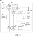
- FIG. 1A is a block diagram of an apparatus in the form of a computing system 100 including a memory device 120 in accordance with a number of embodiments of the present disclosure.
- a memory device 120, memory controller 140, channel controller 143, bank arbiter 145, high speed interface (HSI) 141, memory array 130, sensing circuitry 150, and logic circuitry 170 might also be separately considered an "apparatus.”
- HSA high speed interface
- System 100 includes a host 110 coupled (e.g., connected) to memory device 120, which includes a memory array 130.
- Host 110 can be a host system such as a personal laptop computer, a desktop computer, a digital camera, a smart phone, or a memory card reader, among various other types of hosts.
- Host 110 can include a system motherboard and/or backplane and can include a number of processing resources (e.g., one or more processors, microprocessors, or some other type of controlling circuitry).
- the system 100 can include separate integrated circuits or both the host 110 and the memory device 120 can be on the same integrated circuit.
- the system 100 can be, for instance, a server system and/or a high performance computing (HPC) system and/or a portion thereof.
- HPC high performance computing
- FIG. 1A and 1B illustrates a system having a Von Neumann architecture
- embodiments of the present disclosure can be implemented in non-Von Neumann architectures, which may not include one or more components (e.g., CPU, ALU, etc.) often associated with a Von Neumann architecture.
- components e.g., CPU, ALU, etc.
- the memory array 130 can be a DRAM array, SRAM array, STT RAM array, PCRAM array, TRAM array, RRAM array, NAND flash array, and/or NOR flash array, for instance.
- the array 130 can comprise memory cells arranged in rows coupled by access lines (which may be referred to herein as word lines or select lines) and columns coupled by sense lines, which may be referred to herein as data lines or digit lines. Although a single array 130 is shown in Figure 1 , embodiments are not so limited.
- memory device 120 may include a number of arrays 130 (e.g., a number of banks of DRAM cells, NAND flash cells, etc.).
- the memory device 120 includes address circuitry 142 to latch address signals provided over a data bus 156 (e.g., an I/O bus) through I/O circuitry 144. Status and/or exception information can be provided from the memory controller 140 on the memory device 120 to a channel controller 143, through a high speed interface (HSI) 141 including an out-of-band bus 157 (shown in Figure 1B ), which in turn can be provided from the channel controller 143 to the host 110.
- Address signals are received through address circuitry 142 and decoded by a row decoder 146 and a column decoder 152 to access the memory array 130. Data can be read from memory array 130 by sensing voltage and/or current changes on the data lines using sensing circuitry 150.
- the sensing circuitry 150 can read and latch a page (e.g., row) of data from the memory array 130.
- the I/O circuitry 144 can be used for bi-directional data communication with host 110 over the data bus 156.
- the write circuitry 148 is used to write data to the memory array 130.
- Memory controller 140 decodes signals provided by control bus 154 from the host 110. These signals can include chip enable signals, write enable signals, and address latch signals that are used to control operations performed on the memory array 130, including data read, data write, and data erase operations.
- the memory controller 140 is responsible for executing instructions from the host 110 and sequencing access to the array 130.
- the memory controller 140 can be a state machine, a sequencer, or some other type of controller.
- the controller 140 can control shifting data (e.g., right or left) in an array, e.g., memory array 130.
- the sensing circuitry 150 can comprise a number of sense amplifiers and a number of compute components, which may serve as, and be referred to herein as, an accumulator and can be used to perform logical operations (e.g., on data associated with complementary data lines).
- the sensing circuitry 150 can be used to perform logical operations using data stored in array 130 as inputs and store the results of the logical operations back to the array 130 without transferring data via a sense line address access (e.g., without firing a column decode signal).
- various compute functions can be performed using, and within, sensing circuitry 150 rather than (or in association with) being performed by processing resources external to the sensing circuitry (e.g., by a processor associated with host 110 and/or other processing circuitry, such as ALU circuitry, located on device 120 (e.g., on controller 140 or elsewhere)).
- sensing circuitry 150 is configured to perform logical operations on data stored in memory array 130 and store the result back to the memory array 130 without enabling an I/O line (e.g., a local I/O line) coupled to the sensing circuitry 150.
- the sensing circuitry 150 can be formed on pitch with the memory cells of the array. Additional logic circuitry 170 can be coupled to the sensing circuitry 150 and can be used to store, e.g., cache and/or buffer, results of operations described herein.
- circuitry external to array 130 and sensing circuitry 150 is not needed to perform compute functions as the sensing circuitry 150 can perform the appropriate logical operations to perform such compute functions without the use of an external processing resource. Therefore, the sensing circuitry 150 may be used to compliment and/or to replace, at least to some extent, such an external processing resource (or at least the bandwidth consumption of such an external processing resource).
- the sensing circuitry 150 may be used to perform logical operations (e.g., to execute instructions) in addition to logical operations performed by an external processing resource (e.g., host 110).
- host 110 and/or sensing circuitry 150 may be limited to performing only certain logical operations and/or a certain number of logical operations.
- Enabling an I/O line can include enabling (e.g., turning on) a transistor having a gate coupled to a decode signal (e.g., a column decode signal) and a source/drain coupled to the I/O line.
- a decode signal e.g., a column decode signal
- embodiments are not limited to not enabling an I/O line.
- the sensing circuitry e.g., 150
- the local I/O line(s) may be enabled in order to transfer a result to a suitable location other than back to the array 130 (e.g., to an external register).
- Figure 1B is a block diagram of another apparatus architecture in the form of a computing system 100 including a plurality of memory devices 120-1, ..., 120-N coupled to a host 110 via a channel controller 143 in accordance with a number of embodiments of the present disclosure.
- the channel controller 143 may be coupled to the plurality of memory devices 120-1, ..., 120-N in an integrated manner in the form of a module 118, e.g., formed on same chip with the plurality of memory devices 120-1, ..., 120-N.
- the channel controller 143 may be integrated with the host 110, as illustrated by dashed lines 111, e.g., formed on a separate chip from the plurality of memory devices 120-1, ..., 120-N.
- the channel controller 143 can be coupled to each of the plurality of memory devices 120-1, ..., 120-N via an address and control (A/C) bus 154 as described in Figure 1A which in turn can be coupled to the host 110.
- A/C address and control
- the channel controller 143 can also be coupled to each of the plurality of memory devices, 120-1, ..., 120-N via a data bus 156 as described in Figure 1A which in turn can be coupled to the host 110.
- channel controller 143 can be coupled to each of the plurality of memory devices 120-1, ..., 120-N via an out-of-bound (OOB) bus 157 associated with a high speed interface (HSI) 141, described more in connection with Figures 3-6 , that is configured to report status, exception and other data information to the channel controller 143 to exchange with the host 110.
- OOB out-of-bound
- HSE high speed interface
- the channel controller 143 can receive the status and exception information from a high speed interface (HSI) (also referred to herein as a status channel interface) 141 associated with a bank arbiter 145 in each of the plurality of memory devices 120-1, ..., 120-N.
- HAI high speed interface
- each of the plurality of memory devices 120-1, ..., 120-N can include a bank arbiter 145 to sequence control and data with a plurality of banks, e.g., Bank zero (0), Bank one (1), ..., Bank six (6), Bank seven (7), etc.
- Each of the plurality of banks, Bank 0, ..., Bank 7, can include a memory controller 140 and other components, including an array of memory cells 130 and sensing circuitry 150, additional logic circuitry 170, etc., as described in connection with Figure 1A .
- each of the plurality of banks e.g., Bank 0, .., Bank 7, in the plurality of memory devices 120-1, ..., 120-N can include address circuitry 142 to latch address signals provided over a data bus 156 (e.g., an I/O bus) through I/O circuitry 144.
- Status and/or exception information can be provided from the memory controller 140 on the memory device 120 to the channel controller 143, using the OOB bus 157, which in turn can be provided from the plurality of memory devices 120-1, ..., 120-N to the host 110.
- address signals can be received through address circuitry 142 and decoded by a row decoder 146 and a column decoder 152 to access the memory array 130.
- Data can be read from memory array 130 by sensing voltage and/or current changes on the data lines using sensing circuitry 150.
- the sensing circuitry 150 can read and latch a page (e.g., row) of data from the memory array 130.
- the I/O circuitry 144 can be used for bi-directional data communication with host 110 over the data bus 156.
- the write circuitry 148 is used to write data to the memory array 130 and the OOB bus 157 can be used to report status, exception and other data information to the channel controller 143.
- the channel controller 143 can include one or more local buffers 161 to store an program instructions and can include logic 160 to allocate a plurality of locations, e.g., subarrays, in the arrays of each respective bank to store bank commands, and arguments, (PIM commands) for the various banks associated with to operation of each of the plurality of memory devices 120-1, .. ., 120-N.
- the channel controller 143 can send commands, e.g., PIM commands, to the plurality of memory devices 120-1, ..., 120-N to store those program instructions within a given bank of a memory device.
- the memory array 130 can be a DRAM array, SRAM array, STT RAM array, PCRAM array, TRAM array, RRAM array, NAND flash array, and/or NOR flash array, for instance.
- the array 130 can comprise memory cells arranged in rows coupled by access lines (which may be referred to herein as word lines or select lines) and columns coupled by sense lines, which may be referred to herein as data lines or digit lines.
- a memory controller 140 e.g., bank control logic and/or sequencer, associated with any particular bank, Bank 0, ..., Bank 7, in a given memory device, 120-1, ..., 120-N, can decode signals provided by control bus 154 from the host 110. These signals can include chip enable signals, write enable signals, and address latch signals that are used to control operations performed on the memory array 130, including data read, data write, and data erase operations.
- the memory controller 140 is responsible for executing instructions from the host 110. And, as above, the memory controller 140 can be a state machine, a sequencer, or some other type of controller. The controller 140 can control shifting data (e.g., right or left) in an array, e.g., memory array 130.
- FIG. 1C is a block diagram of a bank 121-1 to a memory device in accordance with a number of embodiments of the present disclosure.
- Bank 121-1 can represent an example bank to a memory device such as Bank 0, ..., Bank 7 (121-0, ..., 121-7) shown in Figure IB.
- a bank architecture can include a plurality of main memory columns (shown horizontally as X), e.g., 16,384 columns in an example DRAM bank. Additionally, the bank 121-1 may be divided up into sections, 123-1, 123-2, ..., 123-N, separated by amplification regions for a data path.
- Each of the of the bank sections 123-1, .., 123-N can include a plurality of rows (shown vertically as Y), e.g., each section may include 16,384 rows in an example DRAM bank.
- Example embodiments are not limited to the example horizontal and/or vertical orientation of columns and rows described here or the example numbers thereof.
- the bank architecture can include additional logic circuitry 170, including sense amplifiers, registers, cache and data buffering, that are coupled to the bank sections 123-1, ..., 123-N.
- the additional logic circuitry 170 can represent another example of the cache 171 associated with the memory controller 140 in Figure 1A or the additional logic array 170 associated with the sensing circuitry 150 and array 130 as shown in Figure 1A .
- the bank architecture can be associated with bank control, e.g., memory controller 140.
- the bank control shown in Figure 1C can, in example, represent at least a portion of the functionality embodied by and contained in the memory controller 140 shown in Figures 1A and IB.
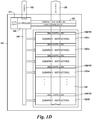
- Figure ID is another block diagram of a bank 121 to a memory device in accordance with a number of embodiments of the present disclosure.
- Bank 121 can represent an example bank to a memory device such as Bank 0, .. ., Bank 7 (121-0, ..., 121-7) shown in Figure IB.
- a bank architecture can include an address/control (A/C) path, e.g., bus, 153 coupled to a memory controller, e.g., controller 140.
- A/C address/control
- controller 140 shown in Figure ID can, in example, represent at least a portion of the functionality embodied by and contained in the memory controller 140 shown in Figures 1A and IB.
- a bank architecture can include a data path, e.g., bus, 155, coupled to a plurality of control/data registers in an instruction and/or data, e.g., program instructions (PIM commands), read path and coupled to a plurality of bank sections, e.g., bank section 123, in a particular bank 121.
- PIM commands program instructions
- a bank section 123 can be further subdivided into a plurality of sub-arrays (or subarrays) 125-1, 125-2, ..., 125-N again separated by of plurality of sensing circuitry and logic circuitry 150/170 as shown in Figure 1A and described further in connection with Figures 2-4 .
- a bank section 121 may be divided into sixteen (16) subarrays. However, embodiments are not limited to this example number.
- Figure ID illustrates an instruction cache 171 associated with the controller 140 and coupled to a write path 149 to each of the subarrays 125-1, .. ., 125-N in the bank section 123.
- the plurality of subarrays 125-1, ..., 125-N and/or portions of the plurality of subarrays may be referred to as a plurality of locations for storing program instructions, e.g., PIM commands, and/or constant data, e.g., data to set up PIM calculations, to a bank section 123 in a memory device.
- program instructions e.g., PIM commands
- constant data e.g., data to set up PIM calculations
- the memory controller 140 e.g. controller 140 shown in Figure ID, is configured to receive a block of instructions and/or constant data from a host, e.g., host 110 in Figure 1A .
- the block of instructions and/or constant data may be received to the memory controller 140 from a channel controller 143 either integrated with the host 110 or separate from the host, e.g., integrated in the form of a module 118 with a plurality of memory devices, 120-1, ..., 120-N, as shown in Figure IB.
- Receiving the block of instructions and/or constant data includes receiving a block of resolved instructions, e.g. PIM commands and/or data to set up PIM calculations, via a data bus 156 coupled to the host 110 and/or controller 143.
- the memory controller 140 is configured to set a series of registers 147 in a bank arbiter 145 and/or in logic circuitry 170.
- the memory controller 140 and/or the bank arbiter 145 are configured to receive a multicast write command to the memory device 120.
- the memory controller 140 and/or the bank arbiter 145 is configured to read the set series of registers and to perform a multicast write operation to store resolved instructions and/or data in an array, e.g., array 130 shown in Figure 1A and/or bank section 123 shown in Figure ID, of a bank, e.g., banks 121-0, ..., 121-7, shown in Figures 1B , 1C and ID.
- the memory controller 140 can include logic in the form of hardware circuitry and/or application specific integrated circuitry (ASIC). The memory controller 140 can thus control multicast data write operations.
- the memory controller 140 is further configured to route the resolved instructions and/or constant data to the sensing circuitry, including a compute component, such as sensing circuitry shown as 150 in Figure 1A and compute components 231 and 331 in Figures 2 and 3 , to perform logical functions and/or operations, e.g., program instruction execution (PIM command execution), as described herein.
- a compute component such as sensing circuitry shown as 150 in Figure 1A and compute components 231 and 331 in Figures 2 and 3 , to perform logical functions and/or operations, e.g., program instruction execution (PIM command execution), as described herein.
- PIM command execution program instruction execution
- the instructions are resolved, e.g. written by a programmer and/or provided to the host 110 and/or controller 143, and are received from a channel controller to a bank arbiter 145 in each of a plurality of memory devices 120-1, ..., 120-N, as shown in Figure IB.
- the memory controller 140 is configured to receive an augmented dynamic random access memory (DRAM) command protocol to indicate when writes are to be performed in a multicast manner.
- DRAM augmented dynamic random access memory
- the memory controller 140 is configured to use DRAM protocol and DRAM logical and electrical interfaces to receive the resolved instructions and/or constant data from the host 110 and/or channel controller 143 and to route the resolved instructions and/or constant data to a compute component of sensing circuitry 150, 250 and/or 350.
- the memory controller 140 is configured to perform a multicast data write operation to resolved locations in a plurality of subarrays and/or portions of a plurality of subarrays in a plurality of banks using the DRAM write path.
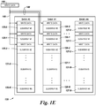
- Figure IE is a block diagram of a plurality of banks to a memory device in accordance with a number of embodiments of the present disclosure.
- a plurality of banks 121-0, ..., 121-N (Bank 0, Bank 1, ..., Bank N) are shown coupled to a memory device 120.
- Each respective bank 121-0, ..., 121-N can include a plurality of subarrays, e.g., 125-0, ..., 125-N and/or portions of subarrays for Bank 0, 126-0, ..., 126-N for Bank 1, and 127-0, ..., 127-N for Bank N.
- the memory device 120 can receive a multicast write command to a bank arbiter 145.
- the bank arbiter can read the series of registers 147 set to resolved locations and send the resolved instructions and/or constant date to the plurality of banks 121-0, ..., 121-N to perform the multicast data write operation in parallel to the plurality of locations for the plurality of banks 121-0, ..., 121-N and for the plurality of subarrays , e.g., 125-0, ..., 125-N for Bank 0, 126-0, ..., 126-N for Bank 1, and 127-0, ..., 127-N for Bank N, in each bank using a write controller/driver 148 and the DRAM write path 149.
- a common set of resolved instructions (data), e.g., PIM commands and/or constant data to set up PIM calculations, is written into three (3) subarrays in each of the first two banks of the memory device 120, e.g., subarrays 125-0, 125-1, and 125-2 of Bank 121-0 and subarrays 126-0, 126-1, and 126-2 of Bank 121-1.
- the channel controller 143 is configured to send the multicast command to select ones of the plurality of memory devices 120-1, . .., 120-N.
- the relevant bank arbiters, 145-1, ..., 145-N are configured to send the resolved instructions and/or constant data to select ones of the plurality of banks, 121-0, ..., 121-7, etc.
- the subarrays and/or portions of subarrays are different among the select ones of the plurality of banks.
- resolved instructions can be received to a plurality of banks via a bank arbiter 145 in each memory device 120 in a plurality of memory devices 120-1, ..., 120-N from a channel controller 143.
- the resolved instructions can be resolved by the channel controller 143.
- a series of registers 147 set to select particular banks 121-0, ..., 121-N, may be provided to the bank arbiter 145.
- a series of registers may additionally be provided to the each of the plurality of banks 121-0, ..., 121-N in association with the memory controller 140 and/or logic circuitry 170.
- a series of registers in a given bank 121 can be set to mask address bits for a plurality of locations in the plurality of banks 121-0, ..., 121-N in each memory device 120. Further, a series of registers can be set in the memory controller 140 of each of the plurality of banks 121-0, ..., 121-N to mask address bits for a plurality of locations of a plurality of subarrays, e.g., 125-0, 125-1, 125-2, or portion of subarrays in each bank, e.g., 121-0.
- a multicast write command can be received to the bank arbiter in the plurality of memory devices from a channel controller 143.
- the series of registers set in the bank arbiter, logic circuitry, and/or set in the memory controllers of the plurality of banks, can be read.
- a multicast data write operation can be performed under the control of the memory controller 140, to write in parallel to the resolved locations for the plurality of banks and for the plurality of subarrays or portions of subarrays in each bank using the DRAM write path. And, the resolved locations for the plurality of subarrays can be different between the resolved locations of the plurality of banks.
- the array of memory cells includes a plurality of banks of memory cells 120-1, .. ., 120-N and the memory device 120 includes a bank arbiter 145 coupled to each of the plurality of banks 120-1, ..., 120-N.
- each bank arbiter is configured to receive a block of instructions including a plurality of program instructions (e.g., PIM commands) and/or constant data relevant to a particular bank from the bank arbiter 145.
- the bank arbiter can receive a multicast write command and read the series of registers 147 associated with in the bank arbiter 145 and send the resolved instruction and/or constant date to the plurality of locations in the plurality of banks 121-0, ..., 121-N.
- the memory controller 140 can then store resolved instructions in the received block of instructions and/or the received constant data to a plurality of locations for the particular bank as allocated by the host 110 and/or channel controller 143.
- the host 110 and/or channel controller 143 can be configured to resolve the instructions, e.g., address translate the plurality of locations, for the bank arbiter 145 to assign to banks of the memory device 120.
- the plurality of locations includes a number of subarrays 125-1, ..., 125-N in the DRAM banks 121-1, ..., 121-7 and/or portions of subarrays.
- each memory controller 140 can be configured to receive program instructions, e.g., PIM commands, and/or constant data, e.g., data to set up PIM calculations, from the host 110 and/or channel controller 143, e.g., on A/C bus 154.
- Each memory controller 140 can be configured to use the techniques described above, to write the PIM commands and/or constant data in parallel to multiple PIM devices.
- a memory controller can be configured to receive a command to start execution of a instruction block received to a given bank, 121-1, ..., 121-7.
- the memory controller 140 may be configured to then retrieve instructions and/or constant data, e.g., on read data path 155 with control and data registers 151, from the plurality of locations for the particular bank and execute using the compute component of the sensing circuity 150.
- the memory controller 140 may cache retrieved instructions and/or constant data local to the particular bank, e.g. in instruction cache 171 and/or logic circuitry 170, to handle branches, loops, logical and data operations contained within the instruction's block execution. So configured, the memory controller 140 can re-cache retrieved instructions and/or constant data as needed.
- the size of a dedicated instruction memory (cache) on a PIM device may not have to be increased for a PIM system.
- the memory controller 140 is configured such that a bank 121 can receive a subsequent instruction block of program instructions and/or constant data relevant to the particular bank and store instructions in the received instruction block and/or received constant data to a plurality of locations for the particular bank while, e.g., in parallel, the memory controller 140 is executing a previously received instruction block or using previous constant data.
- a bank 121 can receive a subsequent instruction block of program instructions and/or constant data relevant to the particular bank and store instructions in the received instruction block and/or received constant data to a plurality of locations for the particular bank while, e.g., in parallel, the memory controller 140 is executing a previously received instruction block or using previous constant data.
- the embodiments described herein avoid needing to wait for future, or a next set of instructions, e.g., PIM commands, to be received from a host 110 and/or channel controller 143.
- the apparatus and methods devices described herein can facilitate a backing store in the PIM device for program instructions and can facilitate pre-writing a subsequent instruction block and/or constant data into allocated locations, while executing a previously received instruction block, in order to facilitate the start of future calculations in the PIM system, e.g., PIM DRAM.
- the memory controller 140 is configure to control the execution of resolved instructions, e.g., PIM commands, and/or access to constant data, e.g., data to set up PIM calculations, by controlling the sensing circuitry 150, including compute components 251 and/or 351, to implement logical functions such as AND, OR, NOT, NAND, NOR, and XOR logical functions. Additionally the memory controller 140 is configured to control the sensing circuitry 150 to perform non-Boolean logic operations, including copy, compare and erase operations, as part of executing program instructions, e.g., PIM commands.
- resolved instructions e.g., PIM commands
- constant data e.g., data to set up PIM calculations
- FIG 2 is a schematic diagram illustrating sensing circuitry 250 in accordance with a number of embodiments of the present disclosure.
- the sensing circuitry 250 can correspond to sensing circuitry 150 shown in Figures 1A and IB.
- the sense amplifier 206 of sensing circuitry 250 can correspond to sense amplifiers 206 shown in Figure 2
- the compute component 231 of sensing circuitry 250 can correspond to sensing circuitry, including compute component, 150 shown in Figure 1A , for example.
- a memory cell comprises a storage element (e.g., capacitor) and an access device (e.g., transistor).
- a first memory cell comprises transistor 202-1 and capacitor 203-1
- a second memory cell comprises transistor 202-2 and capacitor 203-2, etc.
- the memory array 230 is a DRAM array of 1T1C (one transistor one capacitor) memory cells.
- the memory cells may be destructive read memory cells (e.g., reading the data stored in the cell destroys the data such that the data originally stored in the cell is refreshed after being read).
- the cells of the memory array 230 can be arranged in rows coupled by word lines 204-X (Row X), 204-Y (Row Y), etc., and columns coupled by pairs of complementary sense lines (e.g., data lines DIGIT(n-1)/DIGIT(n-1)_, DIGIT(n)/DIGIT(n)_, DIGIT(n+1)/DIGIT(n+1)_)
- the individual sense lines corresponding to each pair of complementary sense lines can also be referred to as data lines 205-1 (D) and 205-2 (D_) respectively.
- Memory cells can be coupled to different data lines and/or word lines.
- a first source/drain region of a transistor 202-1 can be coupled to data line 205-1 (D)
- a second source/drain region of transistor 202-1 can be coupled to capacitor 203-1
- a gate of a transistor 202-1 can be coupled to word line 204-X.
- a first source/drain region of a transistor 202-2 can be coupled to data line 205-2 (D_)
- a second source/drain region of transistor 202-2 can be coupled to capacitor 203-2
- a gate of a transistor 202-2 can be coupled to word line 204-Y.
- the cell plate as shown in Figure 2 , can be coupled to each of capacitors 203-1 and 203-2.
- the cell plate can be a common node to which a reference voltage (e.g., ground) can be applied in various memory array configurations.
- the memory array 230 is coupled to sensing circuitry 250 in accordance with a number of embodiments of the present disclosure.
- the sensing circuitry 250 comprises a sense amplifier 206 and a compute component 231 corresponding to respective columns of memory cells (e.g., coupled to respective pairs of complementary data lines).
- the sense amplifier 206 can be coupled to the pair of complementary sense lines 205-1 and 205-2.
- the compute component 231 can be coupled to the sense amplifier 206 via pass gates 207-1 and 207-2.
- the gates of the pass gates 207-1 and 207-2 can be coupled to logical operation selection logic 213.
- the logical operation selection logic 213 can be configured to include pass gate logic for controlling pass gates that couple the pair of complementary sense lines un-transposed between the sense amplifier 206 and the compute component 231 (as shown in Figure 2 ) and/or swap gate logic for controlling swap gates that couple the pair of complementary sense lines transposed between the sense amplifier 206 and the compute component 231.
- the logical operation selection logic 213 can also be coupled to the pair of complementary sense lines 205-1 and 205-2.
- the logical operation selection logic 213 can be configured to control continuity of pass gates 207-1 and 207-2 based on a selected logical operation, as described in detail below for various configurations of the logical operation selection logic 413.
- the sense amplifier 206 can be operated to determine a data value (e.g., logic state) stored in a selected memory cell.
- the sense amplifier 206 can comprise a cross coupled latch, which can be referred to herein as a primary latch.
- the circuitry corresponding to sense amplifier 206 comprises a latch 215 including four transistors coupled to a pair of complementary data lines D 205-1 and D_ 205-2.
- embodiments are not limited to this example.
- the latch 215 can be a cross coupled latch (e.g., gates of a pair of transistors, such as n-channel transistors (e.g., NMOS transistors) 227-1 and 227-2 are cross coupled with the gates of another pair of transistors, such as p-channel transistors (e.g., PMOS transistors) 229-1 and 229-2).
- the cross coupled latch 215 comprising transistors 227-1, 227-2, 229-1, and 229-2 can be referred to as a primary latch.
- the voltage on one of the data lines 205-1 (D) or 205-2 (D_) will be slightly greater than the voltage on the other one of data lines 205-1 (D) or 205-2 (D_).
- An ACT signal and the RNL* signal can be driven low to enable (e.g., fire) the sense amplifier 206.
- the data lines 205-1 (D) or 205-2 (D_) having the lower voltage will turn on one of the PMOS transistor 229-1 or 229-2 to a greater extent than the other of PMOS transistor 229-1 or 229-2, thereby driving high the data line 205-1 (D) or 205-2 (D_) having the higher voltage to a greater extent than the other data line 205-1 (D) or 205-2 (D_) is driven high.
- the data line 205-1 (D) or 205-2 (D_) having the higher voltage will turn on one of the NMOS transistor 227-1 or 227-2 to a greater extent than the other of the NMOS transistor 227-1 or 227-2, thereby driving low the data line 205-1 (D) or 205-2 (D_) having the lower voltage to a greater extent than the other data line 205-1 (D) or 205-2 (D_) is driven low.
- the data line 205-1 (D) or 205-2 (D_) having the slightly greater voltage is driven to the voltage of the supply voltage V CC through source transistor 211, and the other data line 205-1 (D) or 205-2 (D_) is driven to the voltage of the reference voltage (e.g., ground) through the sink transistor 213.
- the cross coupled NMOS transistors 227-1 and 227-2 and PMOS transistors 229-1 and 229-2 serve as a sense amplifier pair, which amplify the differential voltage on the data lines 205-1 (D) and 205-2 (D_) and operate to latch a data value sensed from the selected memory cell.
- the cross coupled latch of sense amplifier 206 may be referred to as a primary latch 215.
- Embodiments are not limited to the sense amplifier 206 configuration illustrated in Figure 2 .
- the sense amplifier 206 can be current-mode sense amplifier and/or single-ended sense amplifier (e.g., sense amplifier coupled to one data line).
- embodiments of the present disclosure are not limited to a folded data line architecture such as that shown in Figure 2 .
- the sense amplifier 206 can, in conjunction with the compute component 231, be operated to perform various logical operations using data from an array as input.
- the result of a logical operation can be stored back to the array without transferring the data via a data line address access (e.g., without firing a column decode signal such that data is transferred to circuitry external from the array and sensing circuitry via local I/O lines).
- a number of embodiments of the present disclosure can enable performing logical operations and compute functions associated therewith using less power than various previous approaches.
- a number of embodiments eliminate the need to transfer data across I/O lines in order to perform compute functions (e.g., between memory and discrete processor), a number of embodiments can enable an increased parallel processing capability as compared to previous approaches.
- the sense amplifier 206 can further include equilibration circuitry 214, which can be configured to equilibrate the data lines 205-1 (D) and 205-2 (D_).
- the equilibration circuitry 214 comprises a transistor 224 coupled between data lines 205-1 (D) and 205-2 (D_).
- the equilibration circuitry 214 also comprises transistors 225-1 and 225-2 each having a first source/drain region coupled to an equilibration voltage (e.g., V DD /2), where V DD is a supply voltage associated with the array.
- a second source/drain region of transistor 225-1 can be coupled data line 205-1 (D), and a second source/drain region of transistor 225-2 can be coupled data line 205-2 (D_).
- Gates of transistors 224, 225-1, and 225-2 can be coupled together, and to an equilibration (EQ) control signal line 226.
- EQ equilibration
- activating EQ enables the transistors 224, 225-1, and 225-2, which effectively shorts data lines 205-1 (D) and 205-2 (D_) together and to the an equilibration voltage (e.g., V CC /2).
- Figure 2 shows sense amplifier 206 comprising the equilibration circuitry 214
- embodiments are not so limited, and the equilibration circuitry 214 may be implemented discretely from the sense amplifier 206, implemented in a different configuration than that shown in Figure 2 , or not implemented at all.
- the sensing circuitry e.g., sense amplifier 206 and compute component 231
- the sensing circuitry can be operated to perform a selected logical operation and initially store the result in one of the sense amplifier 206 or the compute component 231 without transferring data from the sensing circuitry via an I/O line (e.g., without performing a data line address access via activation of a column decode signal, for instance).
- Boolean logic functions are used in many higher level functions. Consequently, speed and/or power efficiencies that can be realized with improved logical operations, can translate into speed and/or power efficiencies of higher order functionalities.
- the compute component 231 can also comprise a latch, which can be referred to herein as a secondary latch 264.
- the secondary latch 264 can be configured and operated in a manner similar to that described above with respect to the primary latch 215, with the exception that the pair of cross coupled p-channel transistors (e.g., PMOS transistors) comprising the secondary latch can have their respective sources coupled to a supply voltage (e.g., V DD ), and the pair of cross coupled n-channel transistors (e.g., NMOS transistors) of the secondary latch can have their respective sources selectively coupled to a reference voltage (e.g., ground), such that the secondary latch is continuously enabled.
- the configuration of the compute component is not limited to that shown in Figure 2 at 231, and various other embodiments are described further below.
- Figure 3 is a schematic diagram illustrating sensing circuitry capable of implementing an XOR logical operation in accordance with a number of embodiments of the present disclosure.
- Figure 3 shows a sense amplifier 306 coupled to a pair of complementary sense lines 305-1 and 305-2, and a compute component 331 coupled to the sense amplifier 306 via pass gates 307-1 and 307-2.
- the sense amplifier 306 shown in Figure 3 can correspond to sense amplifier 206 shown in Figure 2 .
- the compute component 331 shown in Figure 3 can correspond to sensing circuitry, including compute component, 150 shown in Figure 1A , for example.
- the logical operation selection logic 313 shown in Figure 3 can correspond to logical operation selection logic 413 shown in Figure 4 , for example.
- the gates of the pass gates 307-1 and 307-2 can be controlled by a logical operation selection logic signal, Pass.
- a logical operation selection logic signal Pass.
- an output of the logical operation selection logic can be coupled to the gates of the pass gates 307-1 and 307-2.
- the compute component 331 can comprise a loadable shift register configured to shift data values left and right.
- the compute components 331 can comprise respective stages (e.g., shift cells) of a loadable shift register configured to shift data values left and right.
- each compute component 331 (e.g., stage) of the shift register comprises a pair of right-shift transistors 381 and 386, a pair of left-shift transistors 389 and 390, and a pair of inverters 387 and 388.
- the signals PHASE 1R, PHASE 2R, PHASE 1L, and PHASE 2L can be applied to respective control lines 382, 383, 391 and 392 to enable/disable feedback on the latches of the corresponding compute components 331 in association with performing logical operations and/or shifting data in accordance with embodiments described herein.
- the sensing circuitry shown in Figure 3 also shows a logical operation selection logic 313 coupled to a number of logic selection control input control lines, including ISO, TF, TT, FT, and FF. Selection of a logical operation from a plurality of logical operations is determined from the condition of logic selection control signals on the logic selection control input control lines, as well as the data values present on the pair of complementary sense lines 305-1 and 305-2 when the isolation transistors are enabled via the ISO control signal being asserted.
- the logical operation selection logic 313 can include four logic selection transistors: logic selection transistor 362 coupled between the gates of the swap transistors 342 and a TF signal control line, logic selection transistor 352 coupled between the gates of the pass gates 307-1 and 307-2 and a TT signal control line, logic selection transistor 354 coupled between the gates of the pass gates 307-1 and 307-2 and a FT signal control line, and logic selection transistor 364 coupled between the gates of the swap transistors 342 and a FF signal control line.
- Gates of logic selection transistors 362 and 352 are coupled to the true sense line through isolation transistor 350-1 (having a gate coupled to an ISO signal control line).
- Gates of logic selection transistors 364 and 354 are coupled to the complementary sense line through isolation transistor 350-2 (also having a gate coupled to an ISO signal control line).
- Data values present on the pair of complementary sense lines 305-1 and 305-2 can be loaded into the compute component 331 via the pass gates 307-1 and 307-2.
- the compute component 331 can comprise a loadable shift register.
- the pass gates 307-1 and 307-2 are OPEN, data values on the pair of complementary sense lines 305-1 and 305-2 are passed to the compute component 331 and thereby loaded into the loadable shift register.
- the data values on the pair of complementary sense lines 305-1 and 305-2 can be the data value stored in the sense amplifier 306 when the sense amplifier is fired.
- the logical operation selection logic signal, Pass is high to OPEN the pass gates 307-1 and 307-2.
- the ISO, TF, TT, FT, and FF control signals can operate to select a logical function to implement based on the data value ("B") in the sense amplifier 306 and the data value ("A") in the compute component 331.
- the ISO, TF, TT, FT, and FF control signals are configured to select the logical function to implement independent from the data value present on the pair of complementary sense lines 305-1 and 305-2 (although the result of the implemented logical operation can be dependent on the data value present on the pair of complementary sense lines 305-1 and 305-2.
- the ISO, TF, TT, FT, and FF control signals select the logical operation to implement directly since the data value present on the pair of complementary sense lines 305-1 and 305-2 is not passed through logic to operate the gates of the pass gates 307-1 and 307-2.
- Figure 3 shows swap transistors 342 configured to swap the orientation of the pair of complementary sense lines 305-1 and 305-2 between the sense amplifier 313-7 and the compute component 331.
- the swap transistors 342 are OPEN, data values on the pair of complementary sense lines 305-1 and 305-2 on the sense amplifier 306 side of the swap transistors 342 are oppositely-coupled to the pair of complementary sense lines 305-1 and 305-2 on the compute component 331 side of the swap transistors 342, and thereby loaded into the loadable shift register of the compute component 331.
- the logical operation selection logic signal Pass can be activated (e.g., high) to OPEN the pass gates 307-1 and 307-2 (e.g., conducting) when the ISO control signal line is activated and either the TT control signal is activated (e.g., high) with data value on the true sense line is "1" or the FT control signal is activated (e.g., high) with the data value on the complement sense line is "1.”
- the data value on the true sense line being a "1" OPENs logic selection transistors 352 and 362.
- the data value on the complimentary sense line being a "1" OPENs logic selection transistors 354 and 364. If the ISO control signal or either the respective TT/FT control signal or the data value on the corresponding sense line (e.g., sense line to which the gate of the particular logic selection transistor is coupled) is not high, then the pass gates 307-1 and 307-2 will not be OPENed by a particular logic selection transistor.
- the logical operation selection logic signal PassF can be activated (e.g., high) to OPEN the swap transistors 342 (e.g., conducting) when the ISO control signal line is activated and either the TF control signal is activated (e.g., high) with data value on the true sense line is "1,” or the FF control signal is activated (e.g., high) with the data value on the complement sense line is "1.” If either the respective control signal or the data value on the corresponding sense line (e.g., sense line to which the gate of the particular logic selection transistor is coupled) is not high, then the swap transistors 342 will not be OPENed by a particular logic selection transistor.
- the Pass* control signal is not necessarily complementary to the Pass control signal. It is possible for the Pass and Pass* control signals to both be activated or both be deactivated at the same time. However, activation of both the Pass and Pass* control signals at the same time shorts the pair of complementary sense lines together, which may be a disruptive configuration to be avoided.
- the sensing circuitry illustrated in Figure 3 is configured to select one of a plurality of logical operations to implement directly from the four logic selection control signals (e.g., logical operation selection is not dependent on the data value present on the pair of complementary sense lines). Some combinations of the logic selection control signals can cause both the pass gates 307-1 and 307-2 and swap transistors 342 to be OPEN at the same time, which shorts the pair of complementary sense lines 305-1 and 305-2 together.
- the logical operations which can be implemented by the sensing circuitry illustrated in Figure 3 can be the logical operations summarized in the logic tables shown in Figure 4 .
- Figure 4 is a logic table illustrating selectable logic operation results implemented by a sensing circuitry shown in Figure 3 in accordance with a number of embodiments of the present disclosure.
- the four logic selection control signals e.g., TF, TT, FT, and FF
- the four control signals in conjunction with a particular data value present on the complementary sense lines, can be used to select one of plural logical operations to implement involving the starting data values stored in the sense amplifier 306 and compute component 331.
- the four control signals in conjunction with a particular data value present on the complementary sense lines, controls the continuity of the pass gates 307-1 and 307-2 and swap transistors 342, which in turn affects the data value in the compute component 331 and/or sense amplifier 306 before/after firing.
- the capability to selectably control continuity of the swap transistors 342 facilitates implementing logical operations involving inverse data values (e.g., inverse operands and/or inverse result), among others.
- Logic Table 4-1 illustrated in Figure 4 shows the starting data value stored in the compute component 331 shown in column A at 444, and the starting data value stored in the sense amplifier 306 shown in column B at 445.
- the other 3 column headings in Logic Table 4-1 refer to the continuity of the pass gates 307-1 and 307-2, and the swap transistors 342, which can respectively be controlled to be OPEN or CLOSED depending on the state of the four logic selection control signals (e.g., TF, TT, FT, and FF), in conjunction with a particular data value present on the pair of complementary sense lines 305-1 and 305-2.
- the "Not Open” column corresponds to the pass gates 307-1 and 307-2 and the swap transistors 342 both being in a non-conducting condition
- the "Open True” corresponds to the pass gates 307-1 and 307-2 being in a conducting condition
- the "Open Invert” corresponds to the swap transistors 342 being in a conducting condition.
- the configuration corresponding to the pass gates 307-1 and 307-2 and the swap transistors 342 both being in a conducting condition is not reflected in Logic Table 4-1 since this results in the sense lines being shorted together.
- the nine different selectable logical operations that can be implemented by the sensing circuitry 850 are summarized in Logic Table 4-2 illustrated in Figure 4 , including an XOR logical operation.
- the columns of Logic Table 4-2 illustrated in Figure 4 show a heading 480 that includes the state of logic selection control signals.
- the state of a first logic selection control signal is provided in row 476
- the state of a second logic selection control signal is provided in row 477
- the state of a third logic selection control signal is provided in row 478
- the state of a fourth logic selection control signal is provided in row 479.
- the particular logical operation corresponding to the results is summarized in row 447.
- sensing circuitry sense amplifiers
- compute component dynamic latches
- isolation devices isolation devices
- shift circuitry shift circuitry
Claims (15)
- Vorrichtung, Folgendes umfassend:
eine Speichervorrichtung (120), wobei die Speichervorrichtung Folgendes umfasst:einen Bank-Arbiter (145);mehrere Banken (121-0,..., 121-7), wobei jede Bank der Vielzahl von Banken mit dem Bank-Arbiter gekoppelt ist und Folgendes umfasst;ein Array (130; 230) von Speicherzellen;Abfühlungsschaltungen (150; 250), die über eine Vielzahl von Abfühlleitungen (205-1, 205-2; 305-1, 305-2) mit dem Array gekoppelt sind, wobei die Abfühlungsschaltungen Abfühlverstärker (206; 306) und eine Rechenkomponente (231; 331) einschließen, die konfiguriert ist, um logische Operationen zu implementieren; undeine Speichersteuerung (140), die mit dem Array und den Abfühlungsschaltungen gekoppelt ist, wobei die Speichersteuerung für Folgendes konfiguriert ist:Empfangen eines Blocks aufgelöster Anweisungen von einem Host (110) und/oder einer Kanalsteuerung (143);Festlegen einer Reihe von Registern (147) im Bank-Arbiter (145), wobei die Speichersteuerung (140) und/oder der Bank-Arbiter (145) konfiguriert sind, um einen Multicast-Schreibbefehl an die Speichervorrichtung (120) zu empfangen; undSchreiben der aufgelösten Anweisungen parallel zu einer Vielzahl von Stellen in dem Array. - Vorrichtung nach Anspruch 1, wobei die Speichersteuerung (140) für Folgendes konfiguriert ist:Empfangen aufgelöster konstanter Daten; undSchreiben der aufgelösten konstanten Daten parallel zu einer Vielzahl von Stellen in dem Array (130; 230).
- Vorrichtung nach Anspruch 1, wobei die Speichersteuerung (140) dafür konfiguriert ist, ein DRAM-Protokoll und logische und elektrische DRAM-Schnittstellen zu verwenden, um die Blöcke der aufgelösten Befehle und/oder die konstanten Daten von einem Host (110) zu empfangen.
- Vorrichtung nach Anspruch 3, wobei der Bank-Arbiter für Folgendes konfiguriert ist:Adressübersetzen eines empfangenen Multicast-Befehls; undSenden der aufgelösten Anweisungen und/oder der konstanten Daten an eine Bank (121-0, ..., 121-7), die der Speichersteuerung (140) zugeordnet ist, um parallel zu einer Vielzahl von Stellen in der Bank zu schreiben.
- Vorrichtung nach Anspruch 1, wobei der Bank-Arbiter (145) für Folgendes konfiguriert ist:Adressübersetzen des Multicast-Befehls unter Verwendung einer Reihe von Registern (147), die dem Bank-Arbiter (145) zugeordnet sind; undEmpfangen des Multicast-Befehls über eine Kanalsteuerung (143), die mit dem Host (110) gekoppelt ist.
- Vorrichtung nach einem der Ansprüche 1-5, wobei der Bank-Arbiter für Folgendes konfiguriert ist:Empfangen eines Multicast-Befehls über ein erweitertes dynamisches Direktzugriffsspeicher(dynamic random access memory- DRAM)befehlsprotokoll; undwobei das erweiterte DRAM-Befehlsprotokoll unter Verwendung eines DRAM-Steuerbusses empfangen wird, der mit der Speichervorrichtung (120) gekoppelt ist.
- Vorrichtung nach Anspruch 6, wobei das erweiterte DRAM-Befehlsprotokoll dem Bank-Arbiter (145) anzeigt, dass Schreibvorgänge in einer Multicast-Weise durchzuführen sind.
- Vorrichtung nach einem der Ansprüche 1-5, wobei der Bank-Arbiter eine Logik zum Setzen von Bankadressbits und Zeilenadressbits in einer Reihe von Registern (147) für eine Vielzahl von Stellen in der Vielzahl von Banken (121-0,..., 121-7) umfasst.
- Vorrichtung nach Anspruch 8, wobei der Bank-Arbiter (145) für Folgendes konfiguriert ist: Empfangen eines Multicast-Schreibbefehls über einen DRAM-Steuerbus, der mit der Speichervorrichtung (120) gekoppelt ist;
Lesen der Reihe von Registern (147); und
Senden der aufgelösten Anweisungen und/oder der konstanten Daten an eine Speichersteuerung, um parallel zu der Vielzahl von Stellen zu schreiben. - Vorrichtung nach einem der Ansprüche 1-5, wobei die aufgelösten Anweisungen Prozessor-in-Speicher(processor-in-memory- PIM)-Befehle beinhalten.
- Verfahren zum Betreiben einer Speichervorrichtung, um parallel zu einer Vielzahl von Stellen zu schreiben, Folgendes umfassend:Empfangen von aufgelösten Anweisungen und/oder konstanten Daten an die Speichervorrichtung (120), wobei die Speichervorrichtung (120) Folgendes umfasst:einen Bank-Arbiter (145);mehrere Banken (121-0, ..., 121-7), wobei jede Bank der Vielzahl von Banken mit dem Bank-Arbiter gekoppelt ist und Folgendes umfasst; ein Array (130; 230) von Speicherzellen;Abfühlungsschaltungen (150; 250), die mit dem Array gekoppelt sind, wobei die Abfühlungsschaltungen einen Abfühlverstärker (206; 306) und eine Rechenkomponente (231; 331) einschließen, die konfiguriert ist, um logische Operationen zu implementieren; undeine Speichersteuerung (140), die mit dem Array und den Abfühlungsschaltungen gekoppelt ist, wobei die Speichersteuerung für Folgendes konfiguriert ist:
Empfangen des Blocks aufgelöster Anweisungen von einem Host (110) und/oder einer Kanalsteuerung (143) und Setzen einer Reihe von Registern (147) in dem Bank-Arbiter (145);Empfangen eines Multicast-Schreibbefehls an die Speichervorrichtung (120); undSchreiben des aufgelösten Befehls und/oder der konstanten Daten, um parallel zu der Vielzahl von Stellen in der Speichervorrichtung (120) zu schreiben. - Verfahren nach Anspruch 11, wobei das Verfahren ein Durchführen einer Multicast-Schreiboperation umfasst, um die aufgelösten Anweisungen und/oder die konstanten Daten parallel zu der Vielzahl von Banken (121-0,..., 121-7) der Speichervorrichtung (120) zu schreiben.
- Verfahren nach Anspruch 12, wobei das Verfahren ein paralleles Schreiben des mindestens einenaufgelösten Befehls und/oder der konstanten Daten zu einer Vielzahl von Unterarrays (125-1,..., 125-N) unter der Vielzahl von Banken (121-0, ..., 121-7) der Speichervorrichtung umfasst.
- Verfahren nach Anspruch 13, wobei das Verfahren ein paralleles Schreiben des mindestens einen aufgelösten Befehls und/oder der konstanten Daten zu einer Vielzahl von unterschiedlichen Unterarrays (125-1,..., 125-N) unter der Vielzahl von Banken (121-0, ..., 121-7) der Speichervorrichtung umfasst.
- Verfahren nach einem der Ansprüche 11-14, wobei das Verfahren Folgendes umfasst:Empfangen eines Multicast-Schreibbefehls an der Speichersteuerung (140); undLesen der Reihe von Registern (147), die an der Speichersteuerung eingestellt sind, um die aufgelösten Anweisungen und die konstanten Daten an mehrere Unterarrays (125-1,..., 125-N) in einer Bank (121-0, ..., 121-7) zu senden, die der Speichersteuerung (140) zugeordnet ist.
Applications Claiming Priority (2)
| Application Number | Priority Date | Filing Date | Title |
|---|---|---|---|
| US201562112868P | 2015-02-06 | 2015-02-06 | |
| PCT/US2016/015029 WO2016126474A1 (en) | 2015-02-06 | 2016-01-27 | Apparatuses and methods for parallel writing to multiple memory device locations |
Publications (3)
| Publication Number | Publication Date |
|---|---|
| EP3254286A1 EP3254286A1 (de) | 2017-12-13 |
| EP3254286A4 EP3254286A4 (de) | 2018-08-08 |
| EP3254286B1 true EP3254286B1 (de) | 2019-09-11 |
Family
ID=56564521
Family Applications (1)
| Application Number | Title | Priority Date | Filing Date |
|---|---|---|---|
| EP16746987.3A Active EP3254286B1 (de) | 2015-02-06 | 2016-01-27 | Vorrichtungen und verfahren zum parallelen schreiben an mehrere speichervorrichtungsstandorte |
Country Status (4)
| Country | Link |
|---|---|
| US (4) | US10496286B2 (de) |
| EP (1) | EP3254286B1 (de) |
| CN (1) | CN107408405B (de) |
| WO (1) | WO2016126474A1 (de) |
Families Citing this family (34)
| Publication number | Priority date | Publication date | Assignee | Title |
|---|---|---|---|---|
| WO2016126474A1 (en) * | 2015-02-06 | 2016-08-11 | Micron Technology, Inc. | Apparatuses and methods for parallel writing to multiple memory device locations |
| US10037150B2 (en) * | 2016-07-15 | 2018-07-31 | Advanced Micro Devices, Inc. | Memory controller with virtual controller mode |
| US10559356B2 (en) * | 2017-06-14 | 2020-02-11 | Nxp Usa, Inc. | Memory circuit having concurrent writes and method therefor |
| US10825491B2 (en) * | 2017-12-11 | 2020-11-03 | Micron Technology, Inc. | Systems and methods for writing zeros to a memory array |
| US10402116B2 (en) * | 2017-12-11 | 2019-09-03 | Micron Technology, Inc. | Systems and methods for writing zeros to a memory array |
| US10522210B2 (en) | 2017-12-14 | 2019-12-31 | Micron Technology, Inc. | Apparatuses and methods for subarray addressing |
| US10332586B1 (en) | 2017-12-19 | 2019-06-25 | Micron Technology, Inc. | Apparatuses and methods for subrow addressing |
| US10614875B2 (en) | 2018-01-30 | 2020-04-07 | Micron Technology, Inc. | Logical operations using memory cells |
| US10437557B2 (en) | 2018-01-31 | 2019-10-08 | Micron Technology, Inc. | Determination of a match between data values stored by several arrays |
| US11194477B2 (en) | 2018-01-31 | 2021-12-07 | Micron Technology, Inc. | Determination of a match between data values stored by three or more arrays |
| US10725696B2 (en) | 2018-04-12 | 2020-07-28 | Micron Technology, Inc. | Command selection policy with read priority |
| US10440341B1 (en) | 2018-06-07 | 2019-10-08 | Micron Technology, Inc. | Image processor formed in an array of memory cells |
| KR20210045506A (ko) * | 2018-09-17 | 2021-04-26 | 마이크론 테크놀로지, 인크. | 하이브리드 듀얼 인-라인 메모리 모듈에서의 캐시 작업 |
| US10831693B1 (en) * | 2018-09-27 | 2020-11-10 | Amazon Technologies, Inc. | Multicast master |
| US10613977B1 (en) * | 2018-09-27 | 2020-04-07 | Amazon Technologies, Inc. | Target port with distributed transactions |
| US10769071B2 (en) | 2018-10-10 | 2020-09-08 | Micron Technology, Inc. | Coherent memory access |
| US11175915B2 (en) | 2018-10-10 | 2021-11-16 | Micron Technology, Inc. | Vector registers implemented in memory |
| US10483978B1 (en) | 2018-10-16 | 2019-11-19 | Micron Technology, Inc. | Memory device processing |
| US11184446B2 (en) | 2018-12-05 | 2021-11-23 | Micron Technology, Inc. | Methods and apparatus for incentivizing participation in fog networks |
| US11360704B2 (en) | 2018-12-21 | 2022-06-14 | Micron Technology, Inc. | Multiplexed signal development in a memory device |
| CN111813722B (zh) * | 2019-04-10 | 2022-04-15 | 北京灵汐科技有限公司 | 基于共享内存的数据读写方法,系统及可读存储介质 |
| US10867655B1 (en) | 2019-07-08 | 2020-12-15 | Micron Technology, Inc. | Methods and apparatus for dynamically adjusting performance of partitioned memory |
| US11360768B2 (en) | 2019-08-14 | 2022-06-14 | Micron Technolgy, Inc. | Bit string operations in memory |
| US11513719B2 (en) * | 2019-08-29 | 2022-11-29 | Micron Technology, Inc. | Fast purge on storage devices |
| US11449577B2 (en) | 2019-11-20 | 2022-09-20 | Micron Technology, Inc. | Methods and apparatus for performing video processing matrix operations within a memory array |
| US11741350B2 (en) | 2019-11-27 | 2023-08-29 | Amazon Technologies, Inc. | Efficient utilization of processing element array |
| US11853385B2 (en) | 2019-12-05 | 2023-12-26 | Micron Technology, Inc. | Methods and apparatus for performing diversity matrix operations within a memory array |
| KR20210091404A (ko) * | 2020-01-13 | 2021-07-22 | 삼성전자주식회사 | 메모리 장치, 메모리 모듈 및 메모리 장치의 동작 방법 |
| US11176043B2 (en) | 2020-04-02 | 2021-11-16 | International Business Machines Corporation | Distributed memory-augmented neural network architecture |
| US11227641B1 (en) | 2020-07-21 | 2022-01-18 | Micron Technology, Inc. | Arithmetic operations in memory |
| US11380372B1 (en) * | 2020-12-17 | 2022-07-05 | Micron Technology, Inc. | Transferring data between DRAM and SRAM |
| US20220206685A1 (en) * | 2020-12-31 | 2022-06-30 | Advanced Micro Devices, Inc. | Reusing remote registers in processing in memory |
| US11468001B1 (en) * | 2021-03-30 | 2022-10-11 | Advanced Micro Devices, Inc. | Processing-in-memory concurrent processing system and method |
| US11714571B2 (en) * | 2021-04-26 | 2023-08-01 | Apple Inc. | Address bit dropping to create compacted pipe address for a memory controller |
Family Cites Families (282)
| Publication number | Priority date | Publication date | Assignee | Title |
|---|---|---|---|---|
| US4380046A (en) | 1979-05-21 | 1983-04-12 | Nasa | Massively parallel processor computer |
| JPS6032911B2 (ja) | 1979-07-26 | 1985-07-31 | 株式会社東芝 | 半導体記憶装置 |
| US4435792A (en) | 1982-06-30 | 1984-03-06 | Sun Microsystems, Inc. | Raster memory manipulation apparatus |
| US4727474A (en) | 1983-02-18 | 1988-02-23 | Loral Corporation | Staging memory for massively parallel processor |
| EP0214718A3 (de) | 1985-07-22 | 1990-04-04 | Alliant Computer Systems Corporation | Digitalrechner |
| US5201039A (en) | 1987-09-30 | 1993-04-06 | Mitsubishi Denki Kabushiki Kaisha | Multiple address-space data processor with addressable register and context switching |
| US4843264A (en) | 1987-11-25 | 1989-06-27 | Visic, Inc. | Dynamic sense amplifier for CMOS static RAM |
| US5276643A (en) | 1988-08-11 | 1994-01-04 | Siemens Aktiengesellschaft | Integrated semiconductor circuit |
| JPH0713858B2 (ja) | 1988-08-30 | 1995-02-15 | 三菱電機株式会社 | 半導体記憶装置 |
| US5023838A (en) | 1988-12-02 | 1991-06-11 | Ncr Corporation | Random access memory device with integral logic capability |
| US4958378A (en) | 1989-04-26 | 1990-09-18 | Sun Microsystems, Inc. | Method and apparatus for detecting changes in raster data |
| US5253308A (en) | 1989-06-21 | 1993-10-12 | Amber Engineering, Inc. | Massively parallel digital image data processor using pixel-mapped input/output and relative indexed addressing |
| DE69132495T2 (de) | 1990-03-16 | 2001-06-13 | Texas Instruments Inc | Verteilter Verarbeitungsspeicher |
| US5034636A (en) | 1990-06-04 | 1991-07-23 | Motorola, Inc. | Sense amplifier with an integral logic function |
| US5210850A (en) | 1990-06-15 | 1993-05-11 | Compaq Computer Corporation | Memory address space determination using programmable limit registers with single-ended comparators |
| JP3361825B2 (ja) * | 1990-08-22 | 2003-01-07 | テキサス インスツルメンツ インコーポレイテツド | メモリ・アレイ・アーキテクチャ |
| US5546343A (en) * | 1990-10-18 | 1996-08-13 | Elliott; Duncan G. | Method and apparatus for a single instruction operating multiple processors on a memory chip |
| JPH06103599B2 (ja) | 1990-11-16 | 1994-12-14 | 三菱電機株式会社 | 半導体集積回路装置 |
| US5325519A (en) | 1991-10-18 | 1994-06-28 | Texas Microsystems, Inc. | Fault tolerant computer with archival rollback capabilities |
| FR2685973B1 (fr) | 1992-01-03 | 1994-02-25 | France Telecom | Point memoire pour memoire associative. |
| KR950005095Y1 (ko) | 1992-03-18 | 1995-06-22 | 문정환 | 양방향성 그로벌 비트 라인을 갖는 dram |
| JPH06215160A (ja) | 1992-08-25 | 1994-08-05 | Texas Instr Inc <Ti> | データ処理方法および装置 |
| KR950004854B1 (ko) | 1992-10-08 | 1995-05-15 | 삼성전자 주식회사 | 반도체 메모리 장치 |
| US5440482A (en) | 1993-03-25 | 1995-08-08 | Taligent, Inc. | Forward and reverse Boyer-Moore string searching of multilingual text having a defined collation order |
| US5485373A (en) | 1993-03-25 | 1996-01-16 | Taligent, Inc. | Language-sensitive text searching system with modified Boyer-Moore process |
| US5369622A (en) | 1993-04-20 | 1994-11-29 | Micron Semiconductor, Inc. | Memory with isolated digit lines |
| US5754478A (en) | 1993-04-20 | 1998-05-19 | Micron Technology, Inc. | Fast, low power, write scheme for memory circuits using pulsed off isolation device |
| JP2663838B2 (ja) | 1993-07-27 | 1997-10-15 | 日本電気株式会社 | 半導体集積回路装置 |
| JP3252306B2 (ja) | 1993-08-10 | 2002-02-04 | 株式会社日立製作所 | 半導体不揮発性記憶装置 |
| JP3904244B2 (ja) | 1993-09-17 | 2007-04-11 | 株式会社ルネサステクノロジ | シングル・チップ・データ処理装置 |
| JP3251421B2 (ja) | 1994-04-11 | 2002-01-28 | 株式会社日立製作所 | 半導体集積回路 |
| US5655113A (en) | 1994-07-05 | 1997-08-05 | Monolithic System Technology, Inc. | Resynchronization circuit for a memory system and method of operating same |
| JPH0831168A (ja) | 1994-07-13 | 1996-02-02 | Hitachi Ltd | 半導体記憶装置 |
| US5481500A (en) | 1994-07-22 | 1996-01-02 | International Business Machines Corporation | Precharged bit decoder and sense amplifier with integrated latch usable in pipelined memories |
| US5615404A (en) | 1994-10-31 | 1997-03-25 | Intel Corporation | System having independently addressable bus interfaces coupled to serially connected multi-ported signal distributors generating and maintaining frame based polling schedule favoring isochronous peripherals |
| US5638128A (en) | 1994-11-08 | 1997-06-10 | General Instrument Corporation Of Delaware | Pixel interpolation filters for video decompression processor |
| US5724366A (en) | 1995-05-16 | 1998-03-03 | Mitsubishi Denki Kabushiki Kaisha | Semiconductor memory device |
| KR0146530B1 (ko) | 1995-05-25 | 1998-09-15 | 김광호 | 단속제어회로를 구비한 반도체 메모리 장치와 제어방법 |
| US7301541B2 (en) | 1995-08-16 | 2007-11-27 | Microunity Systems Engineering, Inc. | Programmable processor and method with wide operations |
| JP2812262B2 (ja) | 1995-08-31 | 1998-10-22 | 日本電気株式会社 | 連想記憶装置 |
| US6385634B1 (en) | 1995-08-31 | 2002-05-07 | Intel Corporation | Method for performing multiply-add operations on packed data |
| JP2817836B2 (ja) | 1995-11-30 | 1998-10-30 | 日本電気株式会社 | 半導体メモリ装置 |
| JP3356612B2 (ja) | 1996-02-29 | 2002-12-16 | インターナショナル・ビジネス・マシーンズ・コーポレーション | 高速な輪郭スムージング方法及び装置 |
| US6092186A (en) | 1996-05-07 | 2000-07-18 | Lucent Technologies Inc. | Apparatus and method for aborting un-needed instruction fetches in a digital microprocessor device |
| US5915084A (en) | 1996-09-30 | 1999-06-22 | Advanced Micro Devices, Inc. | Scannable sense amplifier circuit |
| US5991209A (en) | 1997-04-11 | 1999-11-23 | Raytheon Company | Split sense amplifier and staging buffer for wide memory architecture |
| JP3592887B2 (ja) | 1997-04-30 | 2004-11-24 | 株式会社東芝 | 不揮発性半導体記憶装置 |
| US6510098B1 (en) | 1997-05-28 | 2003-01-21 | Cirrus Logic, Inc. | Method and apparatus for transferring data in a dual port memory |
| JPH1115773A (ja) | 1997-06-24 | 1999-01-22 | Matsushita Electron Corp | 半導体集積回路、コンピュータシステム、データ処理装置及びデータ処理方法 |
| US5935263A (en) | 1997-07-01 | 1999-08-10 | Micron Technology, Inc. | Method and apparatus for memory array compressed data testing |
| US6195734B1 (en) | 1997-07-02 | 2001-02-27 | Micron Technology, Inc. | System for implementing a graphic address remapping table as a virtual register file in system memory |
| US6181698B1 (en) | 1997-07-09 | 2001-01-30 | Yoichi Hariguchi | Network routing table using content addressable memory |
| US6025221A (en) | 1997-08-22 | 2000-02-15 | Micron Technology, Inc. | Processing methods of forming integrated circuitry memory devices, methods of forming DRAM arrays, and related semiconductor masks |
| US5991785A (en) | 1997-11-13 | 1999-11-23 | Lucent Technologies Inc. | Determining an extremum value and its index in an array using a dual-accumulation processor |
| US5867429A (en) | 1997-11-19 | 1999-02-02 | Sandisk Corporation | High density non-volatile flash memory without adverse effects of electric field coupling between adjacent floating gates |
| US6163862A (en) | 1997-12-01 | 2000-12-19 | International Business Machines Corporation | On-chip test circuit for evaluating an on-chip signal using an external test signal |
| JP3488612B2 (ja) | 1997-12-11 | 2004-01-19 | 株式会社東芝 | センス増幅回路 |
| US5986942A (en) | 1998-01-20 | 1999-11-16 | Nec Corporation | Semiconductor memory device |
| JPH11260057A (ja) | 1998-03-13 | 1999-09-24 | Nec Corp | 半導体記憶装置 |
| JPH11265995A (ja) | 1998-03-17 | 1999-09-28 | Mitsubishi Electric Corp | 半導体記憶装置 |
| JPH11306751A (ja) | 1998-04-22 | 1999-11-05 | Toshiba Corp | 半導体記憶装置 |
| US6005799A (en) | 1998-08-06 | 1999-12-21 | Silicon Aquarius | Methods and circuits for single-memory dynamic cell multivalue data storage |
| US6141286A (en) | 1998-08-21 | 2000-10-31 | Micron Technology, Inc. | Embedded DRAM architecture with local data drivers and programmable number of data read and data write lines |
| US7409694B2 (en) | 1998-09-09 | 2008-08-05 | Microsoft Corporation | Highly componentized system architecture with loadable virtual memory manager |
| JP2000173269A (ja) | 1998-12-08 | 2000-06-23 | Mitsubishi Electric Corp | 半導体記憶装置 |
| KR100381968B1 (ko) | 1998-12-30 | 2004-03-24 | 주식회사 하이닉스반도체 | 고속동작용디램 |
| US6389507B1 (en) | 1999-01-15 | 2002-05-14 | Gigabus, Inc. | Memory device search system and method |
| US5999435A (en) | 1999-01-15 | 1999-12-07 | Fast-Chip, Inc. | Content addressable memory device |
| US6134164A (en) | 1999-04-22 | 2000-10-17 | International Business Machines Corp. | Sensing circuit for a memory cell array |
| US6741104B2 (en) | 1999-05-26 | 2004-05-25 | Micron Technology, Inc. | DRAM sense amplifier for low voltages |
| JP4748828B2 (ja) * | 1999-06-22 | 2011-08-17 | ルネサスエレクトロニクス株式会社 | 半導体記憶装置 |
| US6535963B1 (en) * | 1999-06-30 | 2003-03-18 | Cisco Technology, Inc. | Memory apparatus and method for multicast devices |
| US6157578A (en) | 1999-07-15 | 2000-12-05 | Stmicroelectronics, Inc. | Method and apparatus for accessing a memory device |
| TW440750B (en) | 1999-08-23 | 2001-06-16 | Seiko Epson Corp | Original plate for display panel and method for manufacturing the display panel, indication machine |
| US6208544B1 (en) | 1999-09-09 | 2001-03-27 | Harris Corporation | Content addressable memory cell providing simultaneous read and compare capability |
| GB2354618B (en) * | 1999-09-24 | 2001-11-14 | Pixelfusion Ltd | Memory devices |
| US6578058B1 (en) | 1999-10-06 | 2003-06-10 | Agilent Technologies, Inc. | System and method for comparing values from target systems |
| US7124221B1 (en) | 1999-10-19 | 2006-10-17 | Rambus Inc. | Low latency multi-level communication interface |
| US6418498B1 (en) | 1999-12-30 | 2002-07-09 | Intel Corporation | Integrated system management memory for system management interrupt handler independent of BIOS and operating system |
| JP4627103B2 (ja) | 2000-01-18 | 2011-02-09 | 富士通セミコンダクター株式会社 | 半導体記憶装置及びその制御方法 |
| AU2000224587A1 (en) | 2000-02-04 | 2001-08-14 | Hitachi Ltd. | Semiconductor device |
| WO2001065359A2 (en) | 2000-02-29 | 2001-09-07 | Peter Petrov | Method and apparatus for building a memory image |
| JP3983969B2 (ja) | 2000-03-08 | 2007-09-26 | 株式会社東芝 | 不揮発性半導体記憶装置 |
| US7028170B2 (en) | 2000-03-08 | 2006-04-11 | Sun Microsystems, Inc. | Processing architecture having a compare capability |
| US6678678B2 (en) | 2000-03-09 | 2004-01-13 | Braodcom Corporation | Method and apparatus for high speed table search |
| JP3822412B2 (ja) | 2000-03-28 | 2006-09-20 | 株式会社東芝 | 半導体記憶装置 |
| US6965648B1 (en) | 2000-05-04 | 2005-11-15 | Sun Microsystems, Inc. | Source synchronous link integrity validation |
| JP2004502267A (ja) | 2000-07-07 | 2004-01-22 | モサイド・テクノロジーズ・インコーポレイテッド | アクセス待ち時間が均一な高速dramアーキテクチャ |
| US6466499B1 (en) | 2000-07-11 | 2002-10-15 | Micron Technology, Inc. | DRAM sense amplifier having pre-charged transistor body nodes |
| AU2001285161A1 (en) | 2000-08-21 | 2002-03-04 | United States Postal Services | Delivery point validation system |
| US6301164B1 (en) | 2000-08-25 | 2001-10-09 | Micron Technology, Inc. | Antifuse method to repair columns in a prefetched output memory architecture |
| US6704828B1 (en) | 2000-08-31 | 2004-03-09 | Micron Technology, Inc. | System and method for implementing data pre-fetch having reduced data lines and/or higher data rates |
| US6948056B1 (en) | 2000-09-28 | 2005-09-20 | Intel Corporation | Maintaining even and odd array pointers to extreme values by searching and comparing multiple elements concurrently where a pointer is adjusted after processing to account for a number of pipeline stages |
| US6304477B1 (en) | 2001-01-31 | 2001-10-16 | Motorola, Inc. | Content addressable magnetic random access memory |
| US6563754B1 (en) | 2001-02-08 | 2003-05-13 | Integrated Device Technology, Inc. | DRAM circuit with separate refresh memory |
| US6650158B2 (en) | 2001-02-21 | 2003-11-18 | Ramtron International Corporation | Ferroelectric non-volatile logic elements |
| US20030018846A1 (en) * | 2001-07-18 | 2003-01-23 | Blaise Fanning | Method and system for fast memory initialization or diagnostics |
| US7546438B2 (en) | 2001-07-19 | 2009-06-09 | Chung Shine C | Algorithm mapping, specialized instructions and architecture features for smart memory computing |
| US6807614B2 (en) | 2001-07-19 | 2004-10-19 | Shine C. Chung | Method and apparatus for using smart memories in computing |
| ITRM20010531A1 (it) | 2001-08-31 | 2003-02-28 | Micron Technology Inc | Dispositivo rilevatore a bassa potenza e alta tensione per memorie ditipo flash. |
| US7260672B2 (en) | 2001-09-07 | 2007-08-21 | Intel Corporation | Using data stored in a destructive-read memory |
| US7062689B2 (en) | 2001-12-20 | 2006-06-13 | Arm Limited | Method and apparatus for memory self testing |
| US20040073773A1 (en) | 2002-02-06 | 2004-04-15 | Victor Demjanenko | Vector processor architecture and methods performed therein |
| US6707729B2 (en) | 2002-02-15 | 2004-03-16 | Micron Technology, Inc. | Physically alternating sense amplifier activation |
| WO2003088048A1 (en) * | 2002-04-08 | 2003-10-23 | University Of Texas System | Non-uniform cache apparatus, systems, and methods |
| AU2003221680A1 (en) | 2002-04-09 | 2003-10-27 | The Research Foundation Of State University Of New York | Multiplier-based processor-in-memory architectures for image and graphics processing |
| JP2003331598A (ja) | 2002-05-13 | 2003-11-21 | Mitsubishi Electric Corp | 半導体記憶装置 |
| US7406494B2 (en) | 2002-05-14 | 2008-07-29 | Texas Instruments Incorporated | Method of generating a cycle-efficient bit-reverse index array for a wireless communication system |
| JP2003346484A (ja) | 2002-05-23 | 2003-12-05 | Mitsubishi Electric Corp | 不揮発性半導体記憶装置 |
| US6789099B2 (en) | 2002-06-10 | 2004-09-07 | International Business Machines Corporation | Sense-amp based adder with source follower evaluation tree |
| US6778435B1 (en) * | 2002-06-12 | 2004-08-17 | T-Ram, Inc. | Memory architecture for TCCT-based memory cells |
| US7054178B1 (en) | 2002-09-06 | 2006-05-30 | Etron Technology, Inc. | Datapath architecture for high area efficiency |
| US6987693B2 (en) | 2002-09-24 | 2006-01-17 | Sandisk Corporation | Non-volatile memory and method with reduced neighboring field errors |
| US7079407B1 (en) | 2002-10-18 | 2006-07-18 | Netlogic Microsystems, Inc. | Content addressable memory (CAM) device including match line sensing |
| US6765834B2 (en) | 2002-11-19 | 2004-07-20 | Hewlett-Packard Development Company, L.P. | System and method for sensing memory cells of an array of memory cells |
| KR100546307B1 (ko) | 2002-12-05 | 2006-01-26 | 삼성전자주식회사 | 글로벌 입출력라인을 프리차지 및/또는 이퀄라이징하기위한 프리차지 회로를 구비하는 반도체 장치 및프리차지 및/또는 이퀄라이즈하는 트랜지스터의 레이아웃 |
| US6731542B1 (en) | 2002-12-05 | 2004-05-04 | Advanced Micro Devices, Inc. | Circuit for accurate memory read operations |
| US6888372B1 (en) | 2002-12-20 | 2005-05-03 | Altera Corporation | Programmable logic device with soft multiplier |
| AU2002353406A1 (en) | 2002-12-27 | 2004-07-22 | Solid State System Co., Ltd. | Nonvolatile memory unit with specific cache |
| US7346903B2 (en) | 2003-02-04 | 2008-03-18 | Sun Microsystems, Inc. | Compiling and linking modules of a cycle-based logic design |
| US6768679B1 (en) | 2003-02-10 | 2004-07-27 | Advanced Micro Devices, Inc. | Selection circuit for accurate memory read operations |
| US6819612B1 (en) | 2003-03-13 | 2004-11-16 | Advanced Micro Devices, Inc. | Apparatus and method for a sense amplifier circuit that samples and holds a reference voltage |
| US6865122B2 (en) | 2003-04-11 | 2005-03-08 | Intel Corporation | Reclaiming blocks in a block-alterable memory |
| US7454451B2 (en) | 2003-04-23 | 2008-11-18 | Micron Technology, Inc. | Method for finding local extrema of a set of values for a parallel processing element |
| US7574466B2 (en) | 2003-04-23 | 2009-08-11 | Micron Technology, Inc. | Method for finding global extrema of a set of shorts distributed across an array of parallel processing elements |
| US7447720B2 (en) | 2003-04-23 | 2008-11-04 | Micron Technology, Inc. | Method for finding global extrema of a set of bytes distributed across an array of parallel processing elements |
| US9015390B2 (en) | 2003-04-25 | 2015-04-21 | Micron Technology, Inc. | Active memory data compression system and method |
| DE10319271A1 (de) | 2003-04-29 | 2004-11-25 | Infineon Technologies Ag | Speicher-Schaltungsanordnung und Verfahren zur Herstellung |
| JP3898152B2 (ja) | 2003-05-27 | 2007-03-28 | ローム株式会社 | 演算機能付き記憶装置および演算記憶方法 |
| DE602004007532T2 (de) | 2003-09-04 | 2008-03-20 | Nxp B.V. | Integrierte schaltung und verfahren zum cache-umabbilden |
| US6956770B2 (en) | 2003-09-17 | 2005-10-18 | Sandisk Corporation | Non-volatile memory and method with bit line compensation dependent on neighboring operating modes |
| US7177183B2 (en) | 2003-09-30 | 2007-02-13 | Sandisk 3D Llc | Multiple twin cell non-volatile memory array and logic block structure and method therefor |
| US7913125B2 (en) | 2003-11-04 | 2011-03-22 | Lsi Corporation | BISR mode to test the redundant elements and regular functional memory to avoid test escapes |
| US6950771B1 (en) | 2003-12-09 | 2005-09-27 | Xilinx, Inc. | Correlation of electrical test data with physical defect data |
| US7401281B2 (en) | 2004-01-29 | 2008-07-15 | International Business Machines Corporation | Remote BIST high speed test and redundancy calculation |
| US7631236B2 (en) | 2004-01-29 | 2009-12-08 | International Business Machines Corporation | Hybrid built-in self test (BIST) architecture for embedded memory arrays and an associated method |
| JP4819316B2 (ja) | 2004-02-23 | 2011-11-24 | ルネサスエレクトロニクス株式会社 | 半導体装置 |
| US7088606B2 (en) | 2004-03-10 | 2006-08-08 | Altera Corporation | Dynamic RAM storage techniques |
| US7020017B2 (en) | 2004-04-06 | 2006-03-28 | Sandisk Corporation | Variable programming of non-volatile memory |
| US7120063B1 (en) | 2004-05-07 | 2006-10-10 | Spansion Llc | Flash memory cell and methods for programming and erasing |
| US8522205B2 (en) | 2004-05-18 | 2013-08-27 | Oracle International Corporation | Packaging multiple groups of read-only files of an application's components into multiple shared libraries |
| JP2006127460A (ja) | 2004-06-09 | 2006-05-18 | Renesas Technology Corp | 半導体装置、半導体信号処理装置、およびクロスバースイッチ |
| US7061817B2 (en) | 2004-06-30 | 2006-06-13 | Micron Technology, Inc. | Data path having grounded precharge operation and test compression capability |
| US7116602B2 (en) | 2004-07-15 | 2006-10-03 | Micron Technology, Inc. | Method and system for controlling refresh to avoid memory cell data losses |
| US20060026432A1 (en) * | 2004-07-30 | 2006-02-02 | Weirauch Charles R | Drive tracking system for removable media |
| US7434024B2 (en) | 2004-08-30 | 2008-10-07 | Ati Technologies, Inc. | SIMD processor with register addressing, buffer stall and methods |
| US20060069849A1 (en) | 2004-09-30 | 2006-03-30 | Rudelic John C | Methods and apparatus to update information in a memory |
| US7685365B2 (en) | 2004-09-30 | 2010-03-23 | Intel Corporation | Transactional memory execution utilizing virtual memory |
| US20060149804A1 (en) | 2004-11-30 | 2006-07-06 | International Business Machines Corporation | Multiply-sum dot product instruction with mask and splat |
| US7230851B2 (en) | 2004-12-23 | 2007-06-12 | Sandisk Corporation | Reducing floating gate to floating gate coupling effect |
| KR100673901B1 (ko) | 2005-01-28 | 2007-01-25 | 주식회사 하이닉스반도체 | 저전압용 반도체 메모리 장치 |
| US7543119B2 (en) | 2005-02-10 | 2009-06-02 | Richard Edward Hessel | Vector processor |
| US7209405B2 (en) | 2005-02-23 | 2007-04-24 | Micron Technology, Inc. | Memory device and method having multiple internal data buses and memory bank interleaving |
| US7624313B2 (en) | 2005-03-28 | 2009-11-24 | Hewlett-Packard Development Company, L.P. | TCAM BIST with redundancy |
| US7196928B2 (en) | 2005-04-05 | 2007-03-27 | Sandisk Corporation | Compensating for coupling during read operations of non-volatile memory |
| US7187585B2 (en) | 2005-04-05 | 2007-03-06 | Sandisk Corporation | Read operation for non-volatile storage that includes compensation for coupling |
| US7193898B2 (en) | 2005-06-20 | 2007-03-20 | Sandisk Corporation | Compensation currents in non-volatile memory read operations |
| KR100720644B1 (ko) | 2005-11-17 | 2007-05-21 | 삼성전자주식회사 | 메모리 장치 및 메모리 그 동작 방법 |
| WO2007069295A1 (ja) | 2005-12-13 | 2007-06-21 | Spansion Llc | 半導体装置およびその制御方法 |
| JP5129450B2 (ja) | 2006-01-16 | 2013-01-30 | ルネサスエレクトロニクス株式会社 | 情報処理装置 |
| US8077533B2 (en) | 2006-01-23 | 2011-12-13 | Freescale Semiconductor, Inc. | Memory and method for sensing data in a memory using complementary sensing scheme |
| JP4989900B2 (ja) | 2006-01-31 | 2012-08-01 | ルネサスエレクトロニクス株式会社 | 並列演算処理装置 |
| US7400532B2 (en) | 2006-02-16 | 2008-07-15 | Micron Technology, Inc. | Programming method to reduce gate coupling interference for non-volatile memory |
| KR100755370B1 (ko) | 2006-04-17 | 2007-09-04 | 삼성전자주식회사 | 반도체 메모리 장치 |
| TW200828333A (en) | 2006-04-28 | 2008-07-01 | Samsung Electronics Co Ltd | Sense amplifier circuit and sense amplifier-based flip-flop having the same |
| US7752417B2 (en) | 2006-06-05 | 2010-07-06 | Oracle America, Inc. | Dynamic selection of memory virtualization techniques |
| US7372715B2 (en) | 2006-06-14 | 2008-05-13 | Micron Technology, Inc. | Architecture and method for NAND flash memory |
| US8395414B2 (en) * | 2006-06-21 | 2013-03-12 | Element Cxi, Llc | Hierarchically-scalable reconfigurable integrated circuit architecture with unit delay modules |
| US8407429B2 (en) * | 2006-06-21 | 2013-03-26 | Element Cxi, Llc | Multi-context configurable memory controller |
| US8390325B2 (en) * | 2006-06-21 | 2013-03-05 | Element Cxi, Llc | Reconfigurable integrated circuit architecture with on-chip configuration and reconfiguration |
| US8069377B2 (en) | 2006-06-26 | 2011-11-29 | Micron Technology, Inc. | Integrated circuit having memory array including ECC and column redundancy and method of operating the same |
| US7724559B2 (en) | 2006-07-14 | 2010-05-25 | International Business Machines Corporation | Self-referenced match-line sense amplifier for content addressable memories |
| US7885119B2 (en) | 2006-07-20 | 2011-02-08 | Sandisk Corporation | Compensating for coupling during programming |
| US7443729B2 (en) | 2006-07-20 | 2008-10-28 | Sandisk Corporation | System that compensates for coupling based on sensing a neighbor using coupling |
| US7692466B2 (en) | 2006-08-18 | 2010-04-06 | Ati Technologies Ulc | Sense amplifier based flip-flop |
| US7805587B1 (en) | 2006-11-01 | 2010-09-28 | Nvidia Corporation | Memory addressing controlled by PTE fields |
| US8151082B2 (en) | 2007-12-06 | 2012-04-03 | Fusion-Io, Inc. | Apparatus, system, and method for converting a storage request into an append data storage command |
| US7471536B2 (en) | 2006-12-08 | 2008-12-30 | Texas Instruments Incorporated | Match mismatch emulation scheme for an addressed location in a CAM |
| US7668040B2 (en) * | 2006-12-22 | 2010-02-23 | Fujitsu Microelectronics Limited | Memory device, memory controller and memory system |
| JP5018074B2 (ja) * | 2006-12-22 | 2012-09-05 | 富士通セミコンダクター株式会社 | メモリ装置,メモリコントローラ及びメモリシステム |
| US7460387B2 (en) | 2007-01-05 | 2008-12-02 | International Business Machines Corporation | eDRAM hierarchical differential sense amp |
| US8145869B2 (en) * | 2007-01-12 | 2012-03-27 | Broadbus Technologies, Inc. | Data access and multi-chip controller |
| US7743303B2 (en) | 2007-01-22 | 2010-06-22 | Micron Technology, Inc. | Defective memory block remapping method and system, and memory device and processor-based system using same |
| US7937535B2 (en) | 2007-02-22 | 2011-05-03 | Arm Limited | Managing cache coherency in a data processing apparatus |
| US7804718B2 (en) | 2007-03-07 | 2010-09-28 | Mosaid Technologies Incorporated | Partial block erase architecture for flash memory |
| US7492640B2 (en) | 2007-06-07 | 2009-02-17 | Sandisk Corporation | Sensing with bit-line lockout control in non-volatile memory |
| JP2009009665A (ja) | 2007-06-29 | 2009-01-15 | Elpida Memory Inc | 半導体記憶装置 |
| US7996749B2 (en) | 2007-07-03 | 2011-08-09 | Altera Corporation | Signal loss detector for high-speed serial interface of a programmable logic device |
| US7489543B1 (en) | 2007-07-25 | 2009-02-10 | Micron Technology, Inc. | Programming multilevel cell memory arrays |
| US7694195B2 (en) | 2007-08-14 | 2010-04-06 | Dell Products L.P. | System and method for using a memory mapping function to map memory defects |
| US7869273B2 (en) | 2007-09-04 | 2011-01-11 | Sandisk Corporation | Reducing the impact of interference during programming |
| US7787319B2 (en) | 2007-09-06 | 2010-08-31 | Innovative Silicon Isi Sa | Sense amplifier circuitry for integrated circuit having memory cell array, and method of operating same |
| US8042082B2 (en) | 2007-09-12 | 2011-10-18 | Neal Solomon | Three dimensional memory in a system on a chip |
| US7965564B2 (en) | 2007-09-18 | 2011-06-21 | Zikbit Ltd. | Processor arrays made of standard memory cells |
| US7663928B2 (en) | 2007-10-09 | 2010-02-16 | Ememory Technology Inc. | Sense amplifier circuit having current mirror architecture |
| US8156299B2 (en) | 2007-10-19 | 2012-04-10 | Virident Systems Inc. | Managing memory systems containing components with asymmetric characteristics |
| US8914612B2 (en) * | 2007-10-29 | 2014-12-16 | Conversant Intellectual Property Management Inc. | Data processing with time-based memory access |
| US7924628B2 (en) | 2007-11-14 | 2011-04-12 | Spansion Israel Ltd | Operation of a non-volatile memory array |
| US7979667B2 (en) | 2007-12-10 | 2011-07-12 | Spansion Llc | Memory array search engine |
| US7755960B2 (en) | 2007-12-17 | 2010-07-13 | Stmicroelectronics Sa | Memory including a performance test circuit |
| US8495438B2 (en) | 2007-12-28 | 2013-07-23 | Texas Instruments Incorporated | Technique for memory imprint reliability improvement |
| US7808854B2 (en) | 2008-02-19 | 2010-10-05 | Kabushiki Kaisha Toshiba | Systems and methods for data transfers between memory cells |
| JP5194302B2 (ja) | 2008-02-20 | 2013-05-08 | ルネサスエレクトロニクス株式会社 | 半導体信号処理装置 |
| US8332580B2 (en) | 2008-04-02 | 2012-12-11 | Zikbit Ltd. | System, method and apparatus for memory with embedded associative section for computations |
| US20090254694A1 (en) | 2008-04-02 | 2009-10-08 | Zikbit Ltd. | Memory device with integrated parallel processing |
| US7957206B2 (en) | 2008-04-04 | 2011-06-07 | Micron Technology, Inc. | Read circuitry for an integrated circuit having memory cells and/or a memory cell array, and method of operating same |
| US8339824B2 (en) | 2008-07-02 | 2012-12-25 | Cooke Laurence H | Nearest neighbor serial content addressable memory |
| US8417921B2 (en) | 2008-08-15 | 2013-04-09 | Apple Inc. | Running-min and running-max instructions for processing vectors using a base value from a key element of an input vector |
| US8555037B2 (en) | 2008-08-15 | 2013-10-08 | Apple Inc. | Processing vectors using wrapping minima and maxima instructions in the macroscalar architecture |
| US8259509B2 (en) | 2008-08-18 | 2012-09-04 | Elpida Memory, Inc. | Semiconductor memory device and method with auxiliary I/O line assist circuit and functionality |
| ITRM20080543A1 (it) | 2008-10-09 | 2010-04-10 | Micron Technology Inc | Architettura e metodo per la programmazione di memorie. |
| KR101596283B1 (ko) | 2008-12-19 | 2016-02-23 | 삼성전자 주식회사 | 개선된 로컬 입출력라인 프리차아지 스킴을 갖는 반도체 메모리 장치 |
| KR101622922B1 (ko) | 2009-03-06 | 2016-05-20 | 삼성전자 주식회사 | 개선된 로컬 입출력라인 프리차아지 스킴을 갖는 반도체 메모리 장치 |
| US8484276B2 (en) | 2009-03-18 | 2013-07-09 | International Business Machines Corporation | Processing array data on SIMD multi-core processor architectures |
| US8473657B2 (en) * | 2009-03-23 | 2013-06-25 | Lsi Corporation | High speed packet FIFO output buffers for switch fabric with speedup |
| KR20100134235A (ko) | 2009-06-15 | 2010-12-23 | 삼성전자주식회사 | 반도체 메모리 장치 |
| US7898864B2 (en) | 2009-06-24 | 2011-03-01 | Sandisk Corporation | Read operation for memory with compensation for coupling based on write-erase cycles |
| US8412985B1 (en) | 2009-06-30 | 2013-04-02 | Micron Technology, Inc. | Hardwired remapped memory |
| US8412987B2 (en) | 2009-06-30 | 2013-04-02 | Micron Technology, Inc. | Non-volatile memory to store memory remap information |
| US8238173B2 (en) | 2009-07-16 | 2012-08-07 | Zikbit Ltd | Using storage cells to perform computation |
| US9076527B2 (en) | 2009-07-16 | 2015-07-07 | Mikamonu Group Ltd. | Charge sharing in a TCAM array |
| JP4951041B2 (ja) | 2009-08-06 | 2012-06-13 | 株式会社東芝 | 半導体記憶装置 |
| US8059438B2 (en) | 2009-08-28 | 2011-11-15 | International Business Machines Corporation | Content addressable memory array programmed to perform logic operations |
| US8077532B2 (en) | 2009-09-02 | 2011-12-13 | Micron Technology, Inc. | Small unit internal verify read in a memory device |
| US8482975B2 (en) | 2009-09-14 | 2013-07-09 | Micron Technology, Inc. | Memory kink checking |
| US8495465B1 (en) | 2009-10-15 | 2013-07-23 | Apple Inc. | Error correction coding over multiple memory pages |
| US20120246380A1 (en) | 2009-10-21 | 2012-09-27 | Avidan Akerib | Neighborhood operations for parallel processing |
| US9477636B2 (en) | 2009-10-21 | 2016-10-25 | Micron Technology, Inc. | Memory having internal processors and data communication methods in memory |
| US8650232B2 (en) | 2009-10-26 | 2014-02-11 | Via Technologies, Inc. | System and method for determination of a horizontal minimum of digital values |
| KR101634340B1 (ko) | 2009-11-03 | 2016-06-28 | 삼성전자주식회사 | 반도체 메모리 장치의 프로그램 방법 |
| US8583896B2 (en) | 2009-11-13 | 2013-11-12 | Nec Laboratories America, Inc. | Massively parallel processing core with plural chains of processing elements and respective smart memory storing select data received from each chain |
| KR20110054773A (ko) | 2009-11-18 | 2011-05-25 | 삼성전자주식회사 | 비트라인 디스털번스를 개선하는 반도체 메모리 장치 |
| US8089815B2 (en) | 2009-11-24 | 2012-01-03 | Sandisk Technologies Inc. | Programming memory with bit line floating to reduce channel-to-floating gate coupling |
| US8605015B2 (en) | 2009-12-23 | 2013-12-10 | Syndiant, Inc. | Spatial light modulator with masking-comparators |
| JP2011146102A (ja) | 2010-01-15 | 2011-07-28 | Elpida Memory Inc | 半導体装置及びデータ処理システム |
| CN102141905B (zh) | 2010-01-29 | 2015-02-25 | 上海芯豪微电子有限公司 | 一种处理器体系结构 |
| US8164942B2 (en) | 2010-02-01 | 2012-04-24 | International Business Machines Corporation | High performance eDRAM sense amplifier |
| US8533245B1 (en) | 2010-03-03 | 2013-09-10 | Altera Corporation | Multipliers with a reduced number of memory blocks |
| WO2011137189A1 (en) | 2010-04-27 | 2011-11-03 | Cornell Research Foundation | System and methods for mapping and searching objects in multidimensional space |
| KR101119371B1 (ko) | 2010-04-29 | 2012-03-06 | 주식회사 하이닉스반도체 | 반도체 메모리 장치 및 이의 동작 방법 |
| US8559232B2 (en) | 2010-05-03 | 2013-10-15 | Aplus Flash Technology, Inc. | DRAM-like NVM memory array and sense amplifier design for high temperature and high endurance operation |
| US8351278B2 (en) | 2010-06-23 | 2013-01-08 | International Business Machines Corporation | Jam latch for latching memory array output data |
| KR101143471B1 (ko) | 2010-07-02 | 2012-05-11 | 에스케이하이닉스 주식회사 | 센스앰프 및 이를 포함하는 반도체 장치 |
| US20120017039A1 (en) | 2010-07-16 | 2012-01-19 | Plx Technology, Inc. | Caching using virtual memory |
| US8462532B1 (en) | 2010-08-31 | 2013-06-11 | Netlogic Microsystems, Inc. | Fast quaternary content addressable memory cell |
| US8347154B2 (en) | 2010-09-21 | 2013-01-01 | International Business Machines Corporation | Use of hashing function to distinguish random and repeat errors in a memory system |
| US8904115B2 (en) | 2010-09-28 | 2014-12-02 | Texas Instruments Incorporated | Cache with multiple access pipelines |
| US8850137B2 (en) * | 2010-10-11 | 2014-09-30 | Cisco Technology, Inc. | Memory subsystem for counter-based and other applications |
| US8332367B2 (en) | 2010-10-20 | 2012-12-11 | International Business Machines Corporation | Parallel data redundancy removal |
| KR101148352B1 (ko) | 2010-11-02 | 2012-05-21 | 에스케이하이닉스 주식회사 | 반도체 메모리 장치 및 그의 동작 방법 |
| JP5528987B2 (ja) | 2010-11-11 | 2014-06-25 | ピーエスフォー ルクスコ エスエイアールエル | 半導体装置 |
| US8553482B2 (en) | 2010-11-29 | 2013-10-08 | Apple Inc. | Sense amplifier and sense amplifier latch having common control |
| WO2012104674A1 (en) | 2011-01-31 | 2012-08-09 | Freescale Semiconductor, Inc. | Integrated circuit device and method for determining an index of an extreme value within an array of values |
| KR20120088973A (ko) | 2011-02-01 | 2012-08-09 | 삼성전자주식회사 | 로컬 센스앰프 회로 및 이를 포함하는 반도체 메모리 장치 |
| JP2012174016A (ja) | 2011-02-22 | 2012-09-10 | Renesas Electronics Corp | データ処理装置およびそのデータ処理方法 |
| JP2012203919A (ja) * | 2011-03-23 | 2012-10-22 | Toshiba Corp | 半導体記憶装置およびその制御方法 |
| JP5259765B2 (ja) | 2011-03-29 | 2013-08-07 | 株式会社東芝 | 不揮発性半導体メモリ |
| US8725730B2 (en) | 2011-05-23 | 2014-05-13 | Hewlett-Packard Development Company, L.P. | Responding to a query in a data processing system |
| US8982649B2 (en) | 2011-08-12 | 2015-03-17 | Gsi Technology, Inc. | Systems and methods involving multi-bank, dual- or multi-pipe SRAMs |
| US8706958B2 (en) | 2011-09-01 | 2014-04-22 | Thomas Hein | Data mask encoding in data bit inversion scheme |
| WO2013062596A1 (en) | 2011-10-28 | 2013-05-02 | Hewlett-Packard Development Company, L.P. | Row shifting shiftable memory |
| US8891297B2 (en) | 2011-11-01 | 2014-11-18 | Micron Technology, Inc. | Memory cell sensing |
| US9830158B2 (en) | 2011-11-04 | 2017-11-28 | Nvidia Corporation | Speculative execution and rollback |
| KR101321481B1 (ko) | 2011-11-04 | 2013-10-28 | 에스케이하이닉스 주식회사 | 반도체 메모리 장치 및 이를 위한 테스트 회로 |
| KR20130052971A (ko) | 2011-11-14 | 2013-05-23 | 삼성전자주식회사 | 비휘발성 메모리 장치의 동작 방법 |
| WO2013078085A1 (en) | 2011-11-22 | 2013-05-30 | Mips Technologies, Inc. | Processor with kernel mode access to user space virtual addresses |
| CN105955704B (zh) | 2011-11-30 | 2018-12-04 | 英特尔公司 | 用于提供向量横向比较功能的指令和逻辑 |
| KR20130072869A (ko) | 2011-12-22 | 2013-07-02 | 에스케이하이닉스 주식회사 | 프리차지 회로 및 비휘발성 메모리 장치 |
| WO2013095592A1 (en) | 2011-12-22 | 2013-06-27 | Intel Corporation | Apparatus and method for vector compute and accumulate |
| US20130286705A1 (en) | 2012-04-26 | 2013-10-31 | David B. Grover | Low power content addressable memory hitline precharge and sensing circuit |
| US8938603B2 (en) | 2012-05-31 | 2015-01-20 | Samsung Electronics Co., Ltd. | Cache system optimized for cache miss detection |
| US20130332707A1 (en) | 2012-06-07 | 2013-12-12 | Intel Corporation | Speed up big-number multiplication using single instruction multiple data (simd) architectures |
| KR102062301B1 (ko) | 2013-01-03 | 2020-01-03 | 삼성전자주식회사 | 메모리 장치의 페이지 복사 방법 및 메모리 시스템의 페이지 관리 방법 |
| US20140215185A1 (en) | 2013-01-29 | 2014-07-31 | Atmel Norway | Fetching instructions of a loop routine |
| US9158667B2 (en) | 2013-03-04 | 2015-10-13 | Micron Technology, Inc. | Apparatuses and methods for performing logical operations using sensing circuitry |
| US9171153B2 (en) | 2013-05-17 | 2015-10-27 | Hewlett-Packard Development Company, L.P. | Bloom filter with memory element |
| US8964496B2 (en) | 2013-07-26 | 2015-02-24 | Micron Technology, Inc. | Apparatuses and methods for performing compare operations using sensing circuitry |
| US8971124B1 (en) | 2013-08-08 | 2015-03-03 | Micron Technology, Inc. | Apparatuses and methods for performing logical operations using sensing circuitry |
| US9430191B2 (en) | 2013-11-08 | 2016-08-30 | Micron Technology, Inc. | Division operations for memory |
| EP3140749B1 (de) | 2014-05-08 | 2021-01-13 | Micron Technology, INC. | Leichte in-speicher-kohärenz |
| CN106462501B (zh) | 2014-05-08 | 2019-07-09 | 美光科技公司 | 基于混合存储器立方体系统互连目录的高速缓冲存储器一致性方法 |
| WO2016126474A1 (en) * | 2015-02-06 | 2016-08-11 | Micron Technology, Inc. | Apparatuses and methods for parallel writing to multiple memory device locations |
-
2016
- 2016-01-27 WO PCT/US2016/015029 patent/WO2016126474A1/en active Application Filing
- 2016-01-27 EP EP16746987.3A patent/EP3254286B1/de active Active
- 2016-01-27 CN CN201680012339.0A patent/CN107408405B/zh active Active
-
2017
- 2017-08-04 US US15/669,538 patent/US10496286B2/en active Active
-
2019
- 2019-06-06 US US16/433,803 patent/US10942652B2/en active Active
-
2021
- 2021-03-08 US US17/195,348 patent/US11681440B2/en active Active
-
2023
- 2023-06-19 US US18/211,356 patent/US20230333744A1/en active Pending
Non-Patent Citations (1)
| Title |
|---|
| None * |
Also Published As
| Publication number | Publication date |
|---|---|
| US20230333744A1 (en) | 2023-10-19 |
| CN107408405B (zh) | 2021-03-05 |
| EP3254286A1 (de) | 2017-12-13 |
| CN107408405A (zh) | 2017-11-28 |
| US10942652B2 (en) | 2021-03-09 |
| US20170336989A1 (en) | 2017-11-23 |
| WO2016126474A1 (en) | 2016-08-11 |
| US11681440B2 (en) | 2023-06-20 |
| EP3254286A4 (de) | 2018-08-08 |
| US20190286337A1 (en) | 2019-09-19 |
| US20210191624A1 (en) | 2021-06-24 |
| US10496286B2 (en) | 2019-12-03 |
Similar Documents
| Publication | Publication Date | Title |
|---|---|---|
| US11681440B2 (en) | Apparatuses and methods for parallel writing to multiple memory device structures | |
| US11263123B2 (en) | Apparatuses and methods for memory device as a store for program instructions | |
| US11599475B2 (en) | Apparatuses and methods for compute enabled cache | |
| US11614877B2 (en) | Apparatuses and methods for data movement | |
| US10074416B2 (en) | Apparatuses and methods for data movement | |
| US11693561B2 (en) | Apparatuses and methods for simultaneous in data path compute operations | |
| US11011220B2 (en) | Apparatuses and methods for compute in data path | |
| US10185674B2 (en) | Apparatus and methods for in data path compute operations |
Legal Events
| Date | Code | Title | Description |
|---|---|---|---|
| STAA | Information on the status of an ep patent application or granted ep patent |
Free format text: STATUS: THE INTERNATIONAL PUBLICATION HAS BEEN MADE |
|
| PUAI | Public reference made under article 153(3) epc to a published international application that has entered the european phase |
Free format text: ORIGINAL CODE: 0009012 |
|
| STAA | Information on the status of an ep patent application or granted ep patent |
Free format text: STATUS: REQUEST FOR EXAMINATION WAS MADE |
|
| 17P | Request for examination filed |
Effective date: 20170809 |
|
| AK | Designated contracting states |
Kind code of ref document: A1 Designated state(s): AL AT BE BG CH CY CZ DE DK EE ES FI FR GB GR HR HU IE IS IT LI LT LU LV MC MK MT NL NO PL PT RO RS SE SI SK SM TR |
|
| AX | Request for extension of the european patent |
Extension state: BA ME |
|
| DAV | Request for validation of the european patent (deleted) | ||
| DAX | Request for extension of the european patent (deleted) | ||
| A4 | Supplementary search report drawn up and despatched |
Effective date: 20180705 |
|
| RIC1 | Information provided on ipc code assigned before grant |
Ipc: G11C 29/26 20060101ALI20180629BHEP Ipc: G11C 7/10 20060101ALI20180629BHEP Ipc: G11C 8/12 20060101ALI20180629BHEP Ipc: G11C 7/06 20060101AFI20180629BHEP Ipc: G06F 15/78 20060101ALI20180629BHEP Ipc: G06F 3/06 20060101ALI20180629BHEP Ipc: G11C 5/02 20060101ALI20180629BHEP |
|
| GRAP | Despatch of communication of intention to grant a patent |
Free format text: ORIGINAL CODE: EPIDOSNIGR1 |
|
| STAA | Information on the status of an ep patent application or granted ep patent |
Free format text: STATUS: GRANT OF PATENT IS INTENDED |
|
| INTG | Intention to grant announced |
Effective date: 20190417 |
|
| GRAS | Grant fee paid |
Free format text: ORIGINAL CODE: EPIDOSNIGR3 |
|
| GRAA | (expected) grant |
Free format text: ORIGINAL CODE: 0009210 |
|
| STAA | Information on the status of an ep patent application or granted ep patent |
Free format text: STATUS: THE PATENT HAS BEEN GRANTED |
|
| AK | Designated contracting states |
Kind code of ref document: B1 Designated state(s): AL AT BE BG CH CY CZ DE DK EE ES FI FR GB GR HR HU IE IS IT LI LT LU LV MC MK MT NL NO PL PT RO RS SE SI SK SM TR |
|
| REG | Reference to a national code |
Ref country code: GB Ref legal event code: FG4D |
|
| REG | Reference to a national code |
Ref country code: CH Ref legal event code: EP |
|
| REG | Reference to a national code |
Ref country code: AT Ref legal event code: REF Ref document number: 1179515 Country of ref document: AT Kind code of ref document: T Effective date: 20190915 |
|
| REG | Reference to a national code |
Ref country code: DE Ref legal event code: R096 Ref document number: 602016020457 Country of ref document: DE |
|
| REG | Reference to a national code |
Ref country code: IE Ref legal event code: FG4D |
|
| REG | Reference to a national code |
Ref country code: NL Ref legal event code: MP Effective date: 20190911 |
|
| REG | Reference to a national code |
Ref country code: LT Ref legal event code: MG4D |
|
| PG25 | Lapsed in a contracting state [announced via postgrant information from national office to epo] |
Ref country code: FI Free format text: LAPSE BECAUSE OF FAILURE TO SUBMIT A TRANSLATION OF THE DESCRIPTION OR TO PAY THE FEE WITHIN THE PRESCRIBED TIME-LIMIT Effective date: 20190911 Ref country code: BG Free format text: LAPSE BECAUSE OF FAILURE TO SUBMIT A TRANSLATION OF THE DESCRIPTION OR TO PAY THE FEE WITHIN THE PRESCRIBED TIME-LIMIT Effective date: 20191211 Ref country code: NO Free format text: LAPSE BECAUSE OF FAILURE TO SUBMIT A TRANSLATION OF THE DESCRIPTION OR TO PAY THE FEE WITHIN THE PRESCRIBED TIME-LIMIT Effective date: 20191211 Ref country code: SE Free format text: LAPSE BECAUSE OF FAILURE TO SUBMIT A TRANSLATION OF THE DESCRIPTION OR TO PAY THE FEE WITHIN THE PRESCRIBED TIME-LIMIT Effective date: 20190911 Ref country code: LT Free format text: LAPSE BECAUSE OF FAILURE TO SUBMIT A TRANSLATION OF THE DESCRIPTION OR TO PAY THE FEE WITHIN THE PRESCRIBED TIME-LIMIT Effective date: 20190911 Ref country code: HR Free format text: LAPSE BECAUSE OF FAILURE TO SUBMIT A TRANSLATION OF THE DESCRIPTION OR TO PAY THE FEE WITHIN THE PRESCRIBED TIME-LIMIT Effective date: 20190911 |
|
| PG25 | Lapsed in a contracting state [announced via postgrant information from national office to epo] |
Ref country code: GR Free format text: LAPSE BECAUSE OF FAILURE TO SUBMIT A TRANSLATION OF THE DESCRIPTION OR TO PAY THE FEE WITHIN THE PRESCRIBED TIME-LIMIT Effective date: 20191212 Ref country code: RS Free format text: LAPSE BECAUSE OF FAILURE TO SUBMIT A TRANSLATION OF THE DESCRIPTION OR TO PAY THE FEE WITHIN THE PRESCRIBED TIME-LIMIT Effective date: 20190911 Ref country code: AL Free format text: LAPSE BECAUSE OF FAILURE TO SUBMIT A TRANSLATION OF THE DESCRIPTION OR TO PAY THE FEE WITHIN THE PRESCRIBED TIME-LIMIT Effective date: 20190911 Ref country code: LV Free format text: LAPSE BECAUSE OF FAILURE TO SUBMIT A TRANSLATION OF THE DESCRIPTION OR TO PAY THE FEE WITHIN THE PRESCRIBED TIME-LIMIT Effective date: 20190911 Ref country code: ES Free format text: LAPSE BECAUSE OF FAILURE TO SUBMIT A TRANSLATION OF THE DESCRIPTION OR TO PAY THE FEE WITHIN THE PRESCRIBED TIME-LIMIT Effective date: 20190911 |
|
| REG | Reference to a national code |
Ref country code: AT Ref legal event code: MK05 Ref document number: 1179515 Country of ref document: AT Kind code of ref document: T Effective date: 20190911 |
|
| PG25 | Lapsed in a contracting state [announced via postgrant information from national office to epo] |
Ref country code: EE Free format text: LAPSE BECAUSE OF FAILURE TO SUBMIT A TRANSLATION OF THE DESCRIPTION OR TO PAY THE FEE WITHIN THE PRESCRIBED TIME-LIMIT Effective date: 20190911 Ref country code: PL Free format text: LAPSE BECAUSE OF FAILURE TO SUBMIT A TRANSLATION OF THE DESCRIPTION OR TO PAY THE FEE WITHIN THE PRESCRIBED TIME-LIMIT Effective date: 20190911 Ref country code: IT Free format text: LAPSE BECAUSE OF FAILURE TO SUBMIT A TRANSLATION OF THE DESCRIPTION OR TO PAY THE FEE WITHIN THE PRESCRIBED TIME-LIMIT Effective date: 20190911 Ref country code: PT Free format text: LAPSE BECAUSE OF FAILURE TO SUBMIT A TRANSLATION OF THE DESCRIPTION OR TO PAY THE FEE WITHIN THE PRESCRIBED TIME-LIMIT Effective date: 20200113 Ref country code: AT Free format text: LAPSE BECAUSE OF FAILURE TO SUBMIT A TRANSLATION OF THE DESCRIPTION OR TO PAY THE FEE WITHIN THE PRESCRIBED TIME-LIMIT Effective date: 20190911 Ref country code: RO Free format text: LAPSE BECAUSE OF FAILURE TO SUBMIT A TRANSLATION OF THE DESCRIPTION OR TO PAY THE FEE WITHIN THE PRESCRIBED TIME-LIMIT Effective date: 20190911 Ref country code: NL Free format text: LAPSE BECAUSE OF FAILURE TO SUBMIT A TRANSLATION OF THE DESCRIPTION OR TO PAY THE FEE WITHIN THE PRESCRIBED TIME-LIMIT Effective date: 20190911 |
|
| PG25 | Lapsed in a contracting state [announced via postgrant information from national office to epo] |
Ref country code: CZ Free format text: LAPSE BECAUSE OF FAILURE TO SUBMIT A TRANSLATION OF THE DESCRIPTION OR TO PAY THE FEE WITHIN THE PRESCRIBED TIME-LIMIT Effective date: 20190911 Ref country code: SK Free format text: LAPSE BECAUSE OF FAILURE TO SUBMIT A TRANSLATION OF THE DESCRIPTION OR TO PAY THE FEE WITHIN THE PRESCRIBED TIME-LIMIT Effective date: 20190911 Ref country code: SM Free format text: LAPSE BECAUSE OF FAILURE TO SUBMIT A TRANSLATION OF THE DESCRIPTION OR TO PAY THE FEE WITHIN THE PRESCRIBED TIME-LIMIT Effective date: 20190911 Ref country code: IS Free format text: LAPSE BECAUSE OF FAILURE TO SUBMIT A TRANSLATION OF THE DESCRIPTION OR TO PAY THE FEE WITHIN THE PRESCRIBED TIME-LIMIT Effective date: 20200224 |
|
| REG | Reference to a national code |
Ref country code: DE Ref legal event code: R097 Ref document number: 602016020457 Country of ref document: DE |
|
| PLBE | No opposition filed within time limit |
Free format text: ORIGINAL CODE: 0009261 |
|
| STAA | Information on the status of an ep patent application or granted ep patent |
Free format text: STATUS: NO OPPOSITION FILED WITHIN TIME LIMIT |
|
| PG2D | Information on lapse in contracting state deleted |
Ref country code: IS |
|
| PG25 | Lapsed in a contracting state [announced via postgrant information from national office to epo] |
Ref country code: DK Free format text: LAPSE BECAUSE OF FAILURE TO SUBMIT A TRANSLATION OF THE DESCRIPTION OR TO PAY THE FEE WITHIN THE PRESCRIBED TIME-LIMIT Effective date: 20190911 Ref country code: IS Free format text: LAPSE BECAUSE OF FAILURE TO SUBMIT A TRANSLATION OF THE DESCRIPTION OR TO PAY THE FEE WITHIN THE PRESCRIBED TIME-LIMIT Effective date: 20200112 |
|
| 26N | No opposition filed |
Effective date: 20200615 |
|
| PG25 | Lapsed in a contracting state [announced via postgrant information from national office to epo] |
Ref country code: SI Free format text: LAPSE BECAUSE OF FAILURE TO SUBMIT A TRANSLATION OF THE DESCRIPTION OR TO PAY THE FEE WITHIN THE PRESCRIBED TIME-LIMIT Effective date: 20190911 Ref country code: MC Free format text: LAPSE BECAUSE OF FAILURE TO SUBMIT A TRANSLATION OF THE DESCRIPTION OR TO PAY THE FEE WITHIN THE PRESCRIBED TIME-LIMIT Effective date: 20190911 |
|
| REG | Reference to a national code |
Ref country code: CH Ref legal event code: PL |
|
| REG | Reference to a national code |
Ref country code: BE Ref legal event code: MM Effective date: 20200131 |
|
| PG25 | Lapsed in a contracting state [announced via postgrant information from national office to epo] |
Ref country code: LU Free format text: LAPSE BECAUSE OF NON-PAYMENT OF DUE FEES Effective date: 20200127 |
|
| PG25 | Lapsed in a contracting state [announced via postgrant information from national office to epo] |
Ref country code: BE Free format text: LAPSE BECAUSE OF NON-PAYMENT OF DUE FEES Effective date: 20200131 Ref country code: LI Free format text: LAPSE BECAUSE OF NON-PAYMENT OF DUE FEES Effective date: 20200131 Ref country code: CH Free format text: LAPSE BECAUSE OF NON-PAYMENT OF DUE FEES Effective date: 20200131 |
|
| PG25 | Lapsed in a contracting state [announced via postgrant information from national office to epo] |
Ref country code: IE Free format text: LAPSE BECAUSE OF NON-PAYMENT OF DUE FEES Effective date: 20200127 |
|
| PG25 | Lapsed in a contracting state [announced via postgrant information from national office to epo] |
Ref country code: TR Free format text: LAPSE BECAUSE OF FAILURE TO SUBMIT A TRANSLATION OF THE DESCRIPTION OR TO PAY THE FEE WITHIN THE PRESCRIBED TIME-LIMIT Effective date: 20190911 Ref country code: MT Free format text: LAPSE BECAUSE OF FAILURE TO SUBMIT A TRANSLATION OF THE DESCRIPTION OR TO PAY THE FEE WITHIN THE PRESCRIBED TIME-LIMIT Effective date: 20190911 Ref country code: CY Free format text: LAPSE BECAUSE OF FAILURE TO SUBMIT A TRANSLATION OF THE DESCRIPTION OR TO PAY THE FEE WITHIN THE PRESCRIBED TIME-LIMIT Effective date: 20190911 |
|
| PG25 | Lapsed in a contracting state [announced via postgrant information from national office to epo] |
Ref country code: MK Free format text: LAPSE BECAUSE OF FAILURE TO SUBMIT A TRANSLATION OF THE DESCRIPTION OR TO PAY THE FEE WITHIN THE PRESCRIBED TIME-LIMIT Effective date: 20190911 |
|
| PGFP | Annual fee paid to national office [announced via postgrant information from national office to epo] |
Ref country code: FR Payment date: 20230124 Year of fee payment: 8 |
|
| PGFP | Annual fee paid to national office [announced via postgrant information from national office to epo] |
Ref country code: GB Payment date: 20230124 Year of fee payment: 8 Ref country code: DE Payment date: 20230127 Year of fee payment: 8 |