EP3239772B1 - Aktuator, kameramodul und anordnung mit der kameramodul - Google Patents
Aktuator, kameramodul und anordnung mit der kameramodul Download PDFInfo
- Publication number
- EP3239772B1 EP3239772B1 EP15872258.7A EP15872258A EP3239772B1 EP 3239772 B1 EP3239772 B1 EP 3239772B1 EP 15872258 A EP15872258 A EP 15872258A EP 3239772 B1 EP3239772 B1 EP 3239772B1
- Authority
- EP
- European Patent Office
- Prior art keywords
- base member
- coil
- frame
- disposed
- module
- Prior art date
- Legal status (The legal status is an assumption and is not a legal conclusion. Google has not performed a legal analysis and makes no representation as to the accuracy of the status listed.)
- Not-in-force
Links
Images


Classifications
-
- G—PHYSICS
- G03—PHOTOGRAPHY; CINEMATOGRAPHY; ANALOGOUS TECHNIQUES USING WAVES OTHER THAN OPTICAL WAVES; ELECTROGRAPHY; HOLOGRAPHY
- G03B—APPARATUS OR ARRANGEMENTS FOR TAKING PHOTOGRAPHS OR FOR PROJECTING OR VIEWING THEM; APPARATUS OR ARRANGEMENTS EMPLOYING ANALOGOUS TECHNIQUES USING WAVES OTHER THAN OPTICAL WAVES; ACCESSORIES THEREFOR
- G03B5/00—Adjustment of optical system relative to image or object surface other than for focusing
-
- H—ELECTRICITY
- H04—ELECTRIC COMMUNICATION TECHNIQUE
- H04N—PICTORIAL COMMUNICATION, e.g. TELEVISION
- H04N23/00—Cameras or camera modules comprising electronic image sensors; Control thereof
- H04N23/60—Control of cameras or camera modules
- H04N23/68—Control of cameras or camera modules for stable pick-up of the scene, e.g. compensating for camera body vibrations
- H04N23/681—Motion detection
- H04N23/6815—Motion detection by distinguishing pan or tilt from motion
-
- G—PHYSICS
- G02—OPTICS
- G02B—OPTICAL ELEMENTS, SYSTEMS OR APPARATUS
- G02B27/00—Optical systems or apparatus not provided for by any of the groups G02B1/00 - G02B26/00, G02B30/00
- G02B27/64—Imaging systems using optical elements for stabilisation of the lateral and angular position of the image
- G02B27/646—Imaging systems using optical elements for stabilisation of the lateral and angular position of the image compensating for small deviations, e.g. due to vibration or shake
-
- H—ELECTRICITY
- H04—ELECTRIC COMMUNICATION TECHNIQUE
- H04N—PICTORIAL COMMUNICATION, e.g. TELEVISION
- H04N23/00—Cameras or camera modules comprising electronic image sensors; Control thereof
- H04N23/50—Constructional details
-
- H—ELECTRICITY
- H04—ELECTRIC COMMUNICATION TECHNIQUE
- H04N—PICTORIAL COMMUNICATION, e.g. TELEVISION
- H04N23/00—Cameras or camera modules comprising electronic image sensors; Control thereof
- H04N23/60—Control of cameras or camera modules
- H04N23/65—Control of camera operation in relation to power supply
-
- H—ELECTRICITY
- H04—ELECTRIC COMMUNICATION TECHNIQUE
- H04N—PICTORIAL COMMUNICATION, e.g. TELEVISION
- H04N23/00—Cameras or camera modules comprising electronic image sensors; Control thereof
- H04N23/60—Control of cameras or camera modules
- H04N23/68—Control of cameras or camera modules for stable pick-up of the scene, e.g. compensating for camera body vibrations
- H04N23/682—Vibration or motion blur correction
- H04N23/685—Vibration or motion blur correction performed by mechanical compensation
- H04N23/687—Vibration or motion blur correction performed by mechanical compensation by shifting the lens or sensor position
-
- G—PHYSICS
- G03—PHOTOGRAPHY; CINEMATOGRAPHY; ANALOGOUS TECHNIQUES USING WAVES OTHER THAN OPTICAL WAVES; ELECTROGRAPHY; HOLOGRAPHY
- G03B—APPARATUS OR ARRANGEMENTS FOR TAKING PHOTOGRAPHS OR FOR PROJECTING OR VIEWING THEM; APPARATUS OR ARRANGEMENTS EMPLOYING ANALOGOUS TECHNIQUES USING WAVES OTHER THAN OPTICAL WAVES; ACCESSORIES THEREFOR
- G03B2205/00—Adjustment of optical system relative to image or object surface other than for focusing
- G03B2205/0007—Movement of one or more optical elements for control of motion blur
-
- G—PHYSICS
- G03—PHOTOGRAPHY; CINEMATOGRAPHY; ANALOGOUS TECHNIQUES USING WAVES OTHER THAN OPTICAL WAVES; ELECTROGRAPHY; HOLOGRAPHY
- G03B—APPARATUS OR ARRANGEMENTS FOR TAKING PHOTOGRAPHS OR FOR PROJECTING OR VIEWING THEM; APPARATUS OR ARRANGEMENTS EMPLOYING ANALOGOUS TECHNIQUES USING WAVES OTHER THAN OPTICAL WAVES; ACCESSORIES THEREFOR
- G03B2205/00—Adjustment of optical system relative to image or object surface other than for focusing
- G03B2205/0053—Driving means for the movement of one or more optical element
- G03B2205/0069—Driving means for the movement of one or more optical element using electromagnetic actuators, e.g. voice coils
Definitions
- the present invention relates to a hand-shake correction actuator, a camera module having a hand-shake correction function, and a camera-mounted device.
- a small-sized camera module is mounted in mobile terminals such as smartphones.
- Such a module often has an auto-focusing function for automatically focusing at the time of capturing a subject and a hand-shake correction function (OIS: Optical Image Stabilization) for reducing irregularities of an image by correcting hand shake (vibration) caused at the time of capturing an image.
- OIS Optical Image Stabilization
- a module tilt method is known in which an imaging module is integrally tilted (for example PTL 1).
- the imaging module is a module having a lens part and an imaging device (for example, a charge coupled device (CCD)), which may be provided with an auto-focusing actuator.
- CCD charge coupled device
- the auto-focusing actuator is referred to as "AF actuator”
- the hand-shake correction actuator is referred to as "OIS actuator.”
- FIG. 1 is an external view illustrating an exemplary camera module of a traditional module tilt type.
- FIG. 2 is an exploded perspective view illustrating the exemplary camera module of a traditional module tilt type.
- camera module 2 of a traditional module tilt type includes fixing part 21, movable part 22, elastic supporting part 23, imaging module 24, and shake detection part 25.
- An OIS actuator is composed of fixing part 21, movable part 22, and elastic supporting part 23.
- Fixing part 21 includes base member 211, coil part 212, and OIS print wiring board 213.
- Coil part 212 is disposed on base member 211.
- OIS print wiring board 213 feeds power to coil part 212, and outputs a detection signal of shake detection part 25 to a control part.
- Movable part 22 includes yoke 221, magnet part 222, top plate 223, and module guide 224. Yoke 221 and magnet part 222 are disposed in respective housing sections formed in top plate 223. Module guide 224 is fixed to top plate 223. Imaging module 24 is fixedly disposed in a space sandwiched between a pair of module guides 224.
- Elastic supporting part 23 has a biaxial gimbal mechanism, and movable part 22 (top plate 223) is fixed to an outer gimbal. Elastic supporting part 23 is disposed at an approximate center of base member 211 in a floating fashion, and fixed by stopper 231. Elastic supporting part 23 supports movable part 22 such that movable part 22 can rotationally sway around the X axis and the Y axis orthogonal to the optical axis (Z axis), that is, elastic supporting part 23 supports movable part 22 such that movable part 22 can be tilted.
- Shake detection part 25 is composed of a gyro sensor that detects the angular velocity of imaging module 24, for example. Shake detection part 25 is fixed to a side surface of module guide 224 of movable part 22. The detection signal of shake detection part 25 is output to the control part through OIS print wiring board 213 that constitutes fixing part 21.
- An OIS voice coil motor (VCM) is composed of coil part 212 and magnet part 222. That is, when a current flows through coil part 212, a Lorentz force is generated at coil part 212 by interaction between the magnetic field of magnet part 222 and a current flowing through coil part 212 (Fleming's left hand rule). Since coil part 212 is fixed, a reactive force is exerted on magnet part 222. This reactive force is the driving force of the OIS voice coil motor. Movable part 22 rotationally sways until the driving force of the OIS voice coil motor and the restoration force (returning force) of elastic supporting part 23 become equivalent to each other.
- PTL2 discloses an imaging device having a base body, a holder holding an optical element, a driving part that moves the holder with respect to the base body in two directions orthogonal to an optical axis and to each other, and a leaf spring that connects the base body and the holder, positions the optical element with respect to the base body, and is elastically deformed upon movement of the holder in the two directions.
- PTL3 discloses a lens driving device having a shake-correction section that corrects shake by moving an autofocusing lens driving section, by which a lens barrel is moved along an optical axis, in first and second directions orthogonal to the optical axis and to each other.
- PTL4 discloses a configuration having a Hall element in a camera module that displaces a lens actuator around an optical axis and in a direction orthogonal to the optical axis.
- An object of the present invention is to provide an actuator, camera module, and camera-mounted device that can achieve further height reduction.
- this object is to provide an actuator, camera module, and camera-mounted device that can achieve further height reduction more surely by reason that a placement region for a driven part (for example, imaging module) is lowered.
- the present invention also intends to provide an actuator, camera module, and camera-mounted device in which it is possible to achieve height reduction and also to reduce the power consumption by improving the magnetic efficiency.
- the number of components is small in comparison with the traditional construction, and therefore it is possible to achieve further height reduction and facilitation of assembling processes.
- a placement region for a driven part (for example, imaging module) is lowered, and therefore further height reduction can be more surely achieved.
- FIGS. 3A and 3B illustrate smartphone M in which camera module 100 according to an embodiment of the present invention is mounted.
- FIG. 3A is a front view of smartphone M
- FIG. 3B is a rear view of smartphone M.
- smartphone M is provided with camera module 100 as a back side camera OC.
- Camera module 100 has an auto-focusing function and a hand-shake correction function, and can capture an image without image blurring by automatically performing focusing at the time of capturing a subject and by correcting hand shake (vibration) caused at the time of capturing an image.
- the hand-shake correction function of camera module 100 is of a module tilt type.
- the module tilt type is advantageous in that no deformation is caused at four corners of the screen.
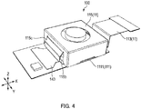
- FIG. 4 is a perspective view of an external appearance of camera module 100.
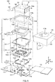
- FIG. 5 is an exploded perspective view of camera module 100.
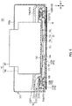
- FIG. 6 is a sectional view of camera module 100 along the Y direction.
- FIG. 7 is a sectional view of camera module 100 along the X direction.
- FIGS. 6 and 7 particularly illustrate a magnetic circuit part that is a voice coil motor.
- Camera module 100 is mounted such that the vertical direction (or horizontal direction) is the X direction, the horizontal direction (or vertical direction) is the Y direction, and the front-rear direction is the Z direction (optical axis direction) at the time of actually capturing an image with smartphone M.
- camera module 100 includes fixing part 11, movable part 12, elastic supporting part 13, imaging module 14, shake detection part 15, displacement detection part 16, and the like.
- OIS actuator A is composed of fixing part 11, movable part 12, and elastic supporting part 13.
- hand-shake correction is performed with use of the driving force of an OIS voice coil motor including coil part 112 and magnet part 122.
- Fixing part 11 is fixed so as to be unmovable when mounted in smartphone M.
- Fixing part 11 supports movable part 12 via elastic supporting part 13 such that movable part 12 is movable.
- Fixing part 11 includes base member 111, coil part 112, OIS print wiring board 113, skirt member (cover member) 114, main body cover member (hereinafter referred to as "cover member”) 115, and print circuit board 117.
- Base member 111 is a member formed of a metal material in a substantially rectangular shape, and is disposed on print circuit board 117.
- Base member 111 is formed of a metal, and as a result the strength is high in comparison with the case where base member 111 is formed of a resin. Thus the thickness of base member 111 can be reduced, and in turn, reduction of the height of camera module 100 can be achieved.
- Base member 111 includes, at the center thereof, protruding part 111a having a truncated pyramid shape for fixing elastic supporting part 13.
- Base member 111 includes, at positions around protruding part 111a, power feeding parts 111b in the form of pads for supplying electricity to coil part 112.
- displacement detection parts 16 are disposed in cutout regions 111C provided at positions around protruding part 111a other than the positions of power feeding parts 111b.
- Displacement detection part 16 is composed of a Hall device or the like, for example, and detects tilt of movable part 12, in particular, an offset of imaging module 14 due to its dead weight (dead weight sagging) when movable part 12 is attached to fixing part 11 via elastic supporting part 13, or detects an offset of imaging module 14 due to the reactive force of the FPC when imaging module 14 is attached to fixing part 11.
- camera module 100 detects and corrects an offset position of imaging module 14 by means of displacement detection part 16, so that imaging module 14 can be precisely disposed without being tilted at the reference position for detection by shake detection part 15.
- base member 111 includes, at the middle portions of four sides constituting the peripheral edge of base member 111, protruding side portions 1111 for positioning cover member 115 and skirt member 114 during fixation thereof Protruding side portions 1111 are respectively engaged with cutouts 1141 and 1151 of skirt member 114 and cover member 115 when skirt member 114 and cover member 115 are attached to base member 111.
- skirt member 114 is fit at the outside of the peripheral edge of base member 111 to be fixedly positioned.
- cover member 115 As for cover member 115, cutout 1151 is engaged with protruding side portion 1111 of base member 111, and cover member 115 is fit at the outside of the outer peripheral surface of skirt member 114. In this way, cover member 115 are also positioned by means of protruding side portions 1111 of base member 111.
- Coil part 112 is composed of four tilt coils 112A to 112D and is disposed at base member 111 to surround protruding part 111a. Coil part 112 (tilt coils 112A to 112D) is disposed such that the winding axis of each coil is oriented in the direction in which base member 111 and yoke (holding member) 120 face each other (in this case, in the Z direction). Power is fed to coil part 112 (tilt coils 112A to 112D) through power feeding parts 111b.
- Tilt coils 112A and 112C face each other in the X direction, and tilt coils 112A and 112C are used to rotationally sway movable part 12 around the Y axis.
- Tilt coils 112B and 112D face each other in the Y direction, and tilt coils 112B and 112D are used to rotationally sway movable part 12 around the X axis.
- OIS print wiring board 113 includes a power-source line (not illustrated) for feeding power to coil part 112.
- OIS print wiring board 113 is fixed on the bottom surface of base member 111, and the power-source line is electrically connected with power feeding parts 111b of base member 111.
- Skirt member 114 is a frame-shaped member composed of four walls 114b coupled with each other in a rectangular shape, and includes reception port 114a for imaging module 14.
- Skirt member 114 includes cutouts 1141 at positions corresponding to protruding side portions 1111 of base member 111, that is, at respective middle portions of lower ends of walls 114b of skirt member 114.
- Skirt member 114 includes, at upper portions of respective walls 114b, restriction parts 114d that slightly protrude from the respective upper portions toward the inside and form a rectangular frame, and restriction parts 114d prevent movable part 12 disposed in the frame, that is, in reception port 114a of skirt member 114 from being excessively tilted.
- skirt member 114 is fixed by being fit at the outside of the peripheral edge of base member 111. Movable part 12 is set between base member 111 and skirt member 114.
- Cover member 115 is a capped rectangular cylindrical member, which includes opening 115a in the cap at the top surface of the cylindrical member. Opening 115a in cover member 115 allows lens part 141 of imaging module 14 to face outside. Cover member 115 includes, at the lower end of its cylindrical peripheral wall, cutouts 1151 formed at positions corresponding to protruding side portions 1111 of base member 111.
- cover member 115 is fit at the outside of skirt member 114 and cutouts 1151 are engaged with protruding side portions 1111 of base member 111, so that cover member 115 is fixed to base member 111.
- Drawing port 115b for imaging-module print wiring board 143 to be pulled to the outside is formed at one side surface of cover member 115.
- a part of one side surface of cover member 115 is processed so as to form outwardly projecting hood part 115c, and drawing port 115b is thus formed below hood part 115c.
- Movable part 12 rotationally sways around the X axis and the Y axis with respect to fixing part 11.
- Movable part 12 includes yoke (holding member) 120, magnet part 122, and positioning plate 126.
- yoke 120 directly holds imaging module 14.
- Imaging module 14 is bonded on the top surface of yoke 120 with a double-sided tape, resin adhesive agent, or the like, for example. With this construction, even without using positioning members such as the module guide disclosed in PTL 1, imaging module 14 can be fixed to yoke 120 with use of a jig while setting the position of imaging module 14 with high accuracy.
- Yoke 120 is a rectangular frame-shaped member formed of a magnetic material, and includes rectangular frame-shaped yoke main body 121 (holding-part main body) and flat frame-shaped holding frame portion 1211 that is provided inside the frame shape of yoke main body 121 and fixes imaging module 14.
- Yoke main body 121 includes flat frame-shaped top plate portion 121a composed of four flat plates which are coupled with each other in a rectangular shape. Magnet part 122 is fixed on the underside of top plate portion 121a.
- Yoke main body 121 includes outside droop portion 121b along the outer peripheral edge of top plate portion 121a (in particular, outer edge of each flat plate composing top plate portion 121a), outside droop portion 121b being formed in such a manner as to downwardly protruding and droop down.
- yoke main body 121 includes inside droop portion 121c along the inner peripheral edge of top plate portion 121a (in particular, inner edge of each flat plate composing top plate portion 121a), inside droop portion 121c being formed in such a manner as to downwardly protruding and droop down. That is, the cross-sectional shape of one side of yoke main body 121 has a recessed shape open toward base member 111, that is, a downwardly open U-shape. Top plate portion 121a that forms the bottom surface inside this recessed shape is located more distant from base member 111 than holding frame portion 1211 is from base member 111.
- holding frame portion 1211 is connected to the lower end of inside droop portion 121c of yoke main body 121.
- the bottom surface of imaging module 14 is fixed on the top surface of holding frame portion 1211 (a part of the top surface of yoke 120) with a double-sided tape or resin adhesive agent.
- top plate portion 121a of yoke main body 121 to which magnet part 122 is fixed is located, by way of inside droop portion 121c, more peripherally and higher than holding frame portion 1211 on which imaging module 14 is fixed. That is, top plate portion 121a is disposed at a position around holding frame portion 1211 and more distant from base member 111 than holding frame portion 1211 is from base member 111 in the Z direction.
- a step by which holding frame portion 1211 is closer to base member 111 than top plate portion 121a is to base member 111 is formed between holding frame portion 1211 and top plate portion 121a, and a recessed portion is formed in the center of entire yoke 120, in which imaging module 14 is fixed.
- Magnet part 122 is composed of four cuboid permanent magnets 122A to 122D corresponding to tilt coils 112A to 112D. Electromagnets may be used in place of permanent magnets. Permanent magnets 122A to 122D have a size which can be put inside tilt coils 112A to 112D.
- Permanent magnets 122A to 122D are disposed at the undersides of respective flat plates of yoke 120 such that the magnetization direction is the Z direction, and permanent magnets 122A to 122D are fixed by bonding, for example.
- permanent magnets 122A to 122D are fixed via positioning plate 126 formed in such a manner as to allow permanent magnets 122A to 122D to be disposed at predetermined positions.
- Positioning plate 126 is formed of a magnetic or non-magnetic material, has a shape corresponding to the shape of the underside of top plate portion 121a, and is provided with four slits at positions to which permanent magnets 122A to 122D are disposed.
- Positioning plate 126 is fixed to the underside of top plate portion 121a with a double-sided tape, adhesive agent, or the like, and permanent magnets 122A to 122D are fitted in the respective slits of positioning plate 126 in such a manner as to make contact with the underside of top plate portion 121a. In this manner, permanent magnets 122A to 122D are positioned and fixed with respect to yoke 120 with high precision (see FIGS. 6 to 8 ).
- permanent magnets 122A to 122D are located between inside droop portion 121c and outside droop portion 121b of yoke 120.
- permanent magnets 122A to 122D face both of inside droop portion 121c and outside droop portion 121b, at which permanent magnets 122A to 122D are spaced apart from both of inside droop portion 121c and outside droop portion 121b.
- Coil part 112 is located between magnet part 122 and yoke 120 (in particular, yoke main body 121) (see FIGS. 5 and 6 ). Magnet part 122 is located on the winding axis of winding of coil part 112. The central portion of coil part 112 are opened along the bonding direction of imaging module 14, and magnet part 122 and coil part 112 are respectively disposed to yoke 120 and base member 111 such that magnet part 122 protrudes to the central portion of coil part 112.
- tilt coils 112A to 112D are located between outside droop portion 121b and permanent magnets 122A to 122D and between inside droop portion 121c and permanent magnets 122A to 122D.
- the periphery of coil part 112 is covered with yoke 120, so that it is possible to prevent the AF actuator 142 of imaging module 14 from being unfavorably influenced by the magnetic field of the energization current of coil part 112.
- magnet part 122 and coil part 112 namely the magnetic circuit part including magnet part 122 and coil part 112 are located peripherally with respect to the lower end of imaging module 14 and holding frame portion 1211 (in particular, farther in the X and Y directions).
- the magnetic circuit part including magnet part 122 and coil part 112 is not disposed directly below the lower end of imaging module 14 and holding frame portion 1211. That is, magnet part 122 (permanent magnets 122A to 122D) and coil part 112 (tilt coils 112A to 112D) are disposed on base member 111 peripherally with respect to the lower end of imaging module 14 and holding frame portion 1211 of yoke 120 in the X and Y directions.
- Elastic supporting part 13 is composed of a rectangular member having a biaxial gimbal mechanism (so-called gimbal spring).
- FIG. 8 is a bottom view of a yoke to which an elastic supporting part is attached, and serves to explain the elastic supporting part.
- elastic supporting part 13 includes center portion 13a and outer gimbal 13c continuously connected with center portion 13a with inner gimbal 13b therebetween. Outer gimbal 13c rotationally sways around the X axis and the Y axis. It is to be noted that the gimbals that are elastic supporting part 13 are indicated by hatching in an attempt to differentiate them from the other components in FIG. 8 .
- center portion 13a has a rectangular frame shape
- inner gimbal 13b has a complex curved shape.
- outer gimbal 13c includes two long plates, which are respectively arranged outside and in parallel with a pair of side portions of center portion 13a that face each other. Outer gimbal 13c is connected to one end of inner gimbal 13b at the middle of outer gimbal 13c. In the meantime, the other end of the inner gimbal is connected to center portion 13a.
- Center portion 13a of elastic supporting part 13 is fit at the outside of protruding part 111a of base member 111 and bonded or welded thereto.
- a peripheral portion with respect to center portion 13a of elastic supporting part 13 is located in such a manner as to be spaced apart from the top surface of base member 111 by a predetermined distance, as illustrated in FIG. 7 .
- this predetermined distance represents a range in which elastic supporting part 13 is movable when elastic supporting part 13 rotationally moves around the central axes in the X and Y directions that are directions in which elastic supporting part 13 is movable.
- this predetermined distance represents a range in which elastic supporting part 13 is movable when elastic supporting part 13 rotationally moves around the central axes in the X and Y directions that are directions in which elastic supporting part 13 is movable.
- outer gimbal 13c of elastic supporting part 13 is bonded or welded to a pair of parallel side portions on the underside of holding frame portion 1211 of yoke 120.
- movable part 12 is disposed at an approximate center of base member 111 in a floating fashion, and thus can rotationally sway around the X axis and the Y axis.
- elastic supporting part 13 is fixed to base member 111 by bonding, it is not necessary to provide lock members such as the stopper disclosed in PTL 1.
- Elastic supporting part 13 is attached via outer gimbal 13c to the underside of holding frame portion 1211, on the top surface of which imaging module 14 is bonded. Accordingly, the distance in the Z direction between elastic supporting part 13 and imaging module 14 substantially corresponds to the thickness of holding frame portion 1211. In this way, the length in the Z direction of camera module 100 itself can be reduced, that is, the height reduction of camera module 100 can be achieved.
- Imaging module 14 includes lens part 141, an imaging device (not illustrated), AF actuator 142, and imaging-module print wiring board 143.
- the imaging device (not illustrated) is composed of, for example, a CCD (charge coupled device) image sensor, a CMOS (complementary metal oxide semiconductor) image sensor, or the like.
- the imaging device (not illustrated) is mounted to imaging-module print wiring board 143.
- the imaging device (not illustrated) captures a subject image imaged by lens part 141.
- AF actuator 142 includes an AF voice coil motor for example, and moves lens part 141 in the light axis direction by utilizing the driving force of AF voice coil motor.
- Publicly known techniques can be applied to AF actuator 142.
- Imaging-module print wiring board 143 is here composed of flexible printed circuits having flexibility.
- Imaging-module print wiring board 143 includes a power-source line (not illustrated) configured to feed power to a coil part (not illustrated) of AF actuator 142, and a video signal line (not illustrated) for video signals output from the imaging device, and a detection signal line (not illustrated) for detection signals output from shake detection part 15.
- imaging-module print wiring board 143 is pulled to the outside through drawing port 115b of cover member 115 from the inside of skirt member 114 and over skirt member 114 in the state where imaging module 14 is mounted in OIS actuator A.
- imaging-module print wiring board 143 extends out upwardly from the underside of imaging module 14, is bent to extend outwardly of a skirt portion, and then extends out from drawing port 115b of cover member 115. Imaging-module print wiring board 143 as pulled out is connected to print circuit board 117 of fixing part 11. As described above, imaging-module print wiring board 143 is flexible, and therefore does not disturb the movement of movable part 12 although imaging-module print wiring board 143 is provided in movable part 12. In the meantime, branching may be provided in imaging-module print wiring board 143 to equip the video signal line and the detection signal line with different connectors.
- Shake detection part 15 detects shake (movement) of imaging module 14.
- Shake detection part 15 is composed of a gyro sensor that detects the angular velocity of imaging module 14, for example.
- Shake detection part 15 is mounted to upright part 143a of imaging-module print wiring board 143.
- the detection signal of shake detection part 15 is output to a control part through imaging-module print wiring board 143.
- the control part controls the energization current of coil part 112 based on the detection signal.
- the control part (not illustrated) may be mounted on imaging-module print wiring board 143 or on print circuit board 117.
- a control part mounted on smartphone M may be utilized via the print wiring board.
- shake detection part 25 is attached to movable part 22 (module guide 224), and the detection signal of shake detection part 25 is output through OIS print wiring board 213 serving as fixing part 21.
- OIS print wiring board 213 serving as fixing part 21.
- the rotational sway of movable part 22 is inhibited by OIS print wiring board 213, and the sensitivity of the tilt operation is reduced, and as a result, the driving force of the OIS actuator is inevitably increased.
- the detection signal of shake detection part 15 is output through imaging-module print wiring board 143 of imaging module 14. That is, OIS print wiring board 113 of fixing part 11 does not inhibit the rotational sway of movable part 12 (imaging module 14). Accordingly, the driving force of OIS actuator A can be reduced in comparison with the traditional technique, and the power consumption can be reduced. In addition, OIS print wiring board 113 of fixing part 11 is used only for power feeding to coil part 112, and therefore may be omitted by separately providing another power-source line. Consequently, cost reduction and space-saving can be achieved.
- coil part 112 and magnet part 122 constituting the magnetic circuit part of the OIS voice coil motor are disposed at positions surrounding imaging module 14 that is an object to be moved.
- the magnetic circuit part including magnet part 122 (permanent magnets 122A to 122D) and coil part 112 (tilt coils 112A to 112D) is disposed on base member 111 peripherally with respect to the lower end of imaging module 14 and holding frame portion 1211 of yoke 120 in the X and Y directions.
- the magnetic circuit part is disposed at such a position that a part of the magnetic circuit part is superimposed on the lower end of imaging module 14 and holding frame portion 1211 of yoke 120 when viewed in the X and Y directions.
- the magnetic circuit part is disposed at such a position that one of magnet part 122 and coil part 112 (in this case, magnet part 122) is superimposed on the lower end of imaging module 14 and holding frame portion 1211 of yoke 120 when viewed in the X and Y directions.
- permanent magnets 122A to 122D constituting magnet part 122 are disposed above tilt coils 112A to 112D constituting coil part 112 and in such a manner as to be partially inserted inside tilt coils 112A to 112D. In this manner, permanent magnets 122A to 122D are disposed above respective tilt coils 112A to 112D along the winding axes directions of respective tilt coils 112A to 112D (Z direction).
- magnet part 122 and coil part 112 are disposed peripherally with respect to the lower end of imaging module 14 and holding frame portion 1211 of yoke 120 in the X and Y directions and at such a position that a part of the magnetic circuit part is superimposed on the lower end of imaging module 14 and holding frame portion 1211 of yoke 120.
- imaging module 14 (movable part 12) is held at a neutral position where the optical axis coincides with the Z direction.
- imaging module 14 movable part 12
- an offset position detected by displacement detection part 16 is corrected to the neutral position where the optical axis coincides with the Z direction.
- movable part 12 including imaging module 14 rotationally sways around the Y axis with center portion 13a of elastic supporting part 13 as a fulcrum.
- movable part 12 including imaging module 14 rotationally sways around the X axis with center portion 13a of elastic supporting part 13 as a fulcrum.
- Movable part 12 rotationally sways until the driving force of the OIS voice coil motor (force which acts on magnet part 122) and the restoration force of elastic supporting part 13 become equivalent to each other.
- the energization current of coil part 112 is controlled based on the detection result of shake detection part 15 such that rotational sway of movable part 12 offsets shake of imaging module 14. In this manner, shift of the optical axis due to hand shake is corrected, and the orientation of the light axis is kept at an orientation.
- restriction part 114d of skirt member 114 limits the rotational sway of movable part 12, it is possible to prevent movable part 12 from being excessively rotationally swayed by the drop impact or the like.
- the bottom surface of imaging module 14 is fixed to the top surface of holding frame portion 1211 of movable part 12 (part of the top surface of yoke 120) with a double-sided tape or resin adhesive agent.
- Holding frame portion 1211 is connected on the peripheral side thereof to top plate portion 121a of yoke main body 121 by way of inside droop portion 121c of yoke main body 121, top plate portion 121a being located at a position more distant from base member 111 in the Z direction than from holding frame portion 1211, that is, at a higher position than from holding frame portion 1211.
- Magnet part 122 is fixed to the underside of top plate portion 121a, and coil part 112 is disposed with respect to magnet part 122 such that when viewed in the Z direction coil part 112 is spaced apart from magnet part 122 and magnet part 122 is located inside coil part 112.
- the magnetic circuit part including magnet part 122 and coil part 112 is disposed peripherally with respect to holding frame portion 1211 (outwardly in the X and Y directions), in other words, peripherally with respect to imaging module 14. In this case, magnet part 122 and coil part 112 are located outside of the range in which imaging module 14 is movable.
- magnet part 122 is fixed on the underside of top plate portion 121a that is arranged at a height level higher than the height level of holding frame portion 1211. That is, magnet part 122 is located peripherally with respect to and higher than holding frame portion 1211 on which imaging module 14 is fixed.
- the magnetic circuit part including magnet part 122 (permanent magnets 122A to 122D) and coil part 112 (tilt coils 112A to 112D) is disposed on base member 111 peripherally with respect to the lower end of imaging module 14 or holding frame portion 1211 of yoke 120 in the X and Y directions.
- the magnetic circuit part is not disposed in a space between base member 111 and imaging module 14 in which the height (in the Z direction) is limited.
- yoke 120 includes in the center thereof the recessed portion defined by yoke main body 121 (in particular, inside droop portion 121c) and holding frame portion 1211, and imaging module 14 is fixed within this recessed portion.
- Actuator A corrects shake by tilting the driven part (imaging module 14) with the driving force of the voice coil motor including magnet part 122 and coil part 112 disposed as mentioned above.
- Actuator A includes: movable part 12 including frame shaped yoke 120 (holding member) on which the driven part (imaging module 14) is bonded, in which magnet part 122 is disposed to yoke main body 121 of yoke 120 (part of the holding member); fixing part 11 including base member 111 and frame shaped skirt member 114 fixed at the peripheral edge of base member 111, in which coil part 112 is disposed to base member 111; and elastic supporting part (supporting part) 13 disposed to base member 111 and configured to support movable part 12 such that movable part 12 can be tilted with respect to fixing part 11.
- Movable part 12 is set between base member 111 and skirt member 114.
- actuator A With actuator A, the number of components is reduced in comparison with the traditional construction, and consequently further height reduction and facilitation of assembling processes are achieved.
- camera module 100 is simply obtained by only bonding imaging module 14 with an auto-focusing function to yoke 120.
- actuator A includes: fixing member 11 including base member 111, in which one of coil part 112 and magnet part 122 is disposed on base member 111 peripherally with respect to the driven part (imaging module 14); movable part 12 including the frame shaped holding member (yoke 120) on a surface (top surface) of which facing away from base member 111 the driven part is placed, in which the other one of coil part 112 and magnet part 122 is disposed peripherally with respect to the driven part on a surface (underside) of the holding member facing base member 111; and the supporting part (elastic supporting part) 13 disposed to base member 111 and configured to support movable part 12 such that movable part 12 can be tilted with respect to fixing part 11.
- the holding member includes a step by which a placement region (holding frame portion 1211) for the driven part is closer to base member 111 than a disposition region (top plate portion 121a) for one of coil part 112 and magnet part 122 is to base member 111.
- the placement region in yoke 120 for imaging module 14 can be lower than the disposition region for coil part 112 or magnet part 122, and therefore further height reduction can be more surely achieved.
- the height of the magnetic circuit part that is, the lengths of coil part 112 and magnet part 122 are not limited, and accordingly a decrease in the magnetic efficiency and an accompanying increase in the power consumption are not caused.
- the height (length in the Z direction) of coil part 112 can be greater by increasing the number of turns of coil part 112 (tilt coils 112A to 112D), or the length in the Z direction of magnet part 122 (permanent magnets 122A to 122D) can be increased. In this way, the magnetic force can be greater, so that it is possible to improve the magnetic efficiency and/or to reduce the power consumption.
- coil part 112 (tilt coils 112A to 112D) is disposed such that the winding axis of coil part 112 (tilt coils 112A to 112D) is oriented in the direction in which base member 111 and holding member (yoke) 120 face each other.
- Magnet part 122 (permanent magnets 122A to 122D) is disposed in such a manner as to protrude to the central portion of coil part 112 (tilt coils 112A to 112D). In this manner, coil part 112 and magnet part 122 can be enlarged in the height direction (Z direction) without coil part 112 and magnet part 122 being enlarged peripherally (in the X and Y directions). In this way, the construction of the magnetic circuit part itself can be enlarged without the disposition space in actuator A for the magnetic circuit part itself being enlarged.
- the actuator of the embodiment is of a so-called moving magnet type in which fixing part 11 includes coil part 112 and movable part 12 includes magnet part 122
- the present invention may be applied to an actuator of a so-called moving coil type in which a fixing part includes a magnet part and a movable part includes a coil part.
- a yoke is also disposed to the fixing part.
- two pairs of tilt coil 112A and permanent magnet 122A and tilt coil 112C and permanent magnet 122C are disposed as the voice coil motor that rotationally sways movable part 12 around the X axis
- two pairs of tilt coil 112B and permanent magnet 122B and tilt coil 112D and permanent magnet 122D are disposed as the voice coil motor that rotationally sways movable part 12 around the Y axis
- at least one pair is disposed as each of the voice coil motors.
- photo reflectors magnetic sensors, inductance detection with a coil, strain sensors, or the like may also be adopted as shake detection part 15 instead of gyro sensors.
- a detection device for example a photodetector of a photo reflector, a Hall device of a magnetic sensor or the like
- each component (in particular, magnet part 122) of actuator A is formed of a highly heat-resistant material. Soldering of a reflow type can thus be employed.
- a conductive shield case may be provided on the outside of camera module 100.
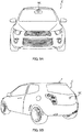
- FIGS. 9A and 9B illustrate vehicle C in which onboard camera module VC (Vehicle Camera) is mounted.
- FIG. 9A is a front view of vehicle C and FIG.
- Camera module 100 as described in the embodiment is mounted on vehicle C as onboard camera module VC, for example.
- Onboard camera module VC is used for rear monitoring, drive recording, collision avoidance control, automatic drive control, and the like.
- the actuator, camera module, and camera-mounted device according to the present invention have an advantage that further height reduction can be achieved, and the actuator, camera module, and camera-mounted device are useful as a device applicable to information devices including mobile terminals such as smartphones, transporting devices such as automobiles, onboard camera-equipped devices, and the like.
Landscapes
- Engineering & Computer Science (AREA)
- Multimedia (AREA)
- Signal Processing (AREA)
- Physics & Mathematics (AREA)
- General Physics & Mathematics (AREA)
- Optics & Photonics (AREA)
- Adjustment Of Camera Lenses (AREA)
- Studio Devices (AREA)
- Fittings On The Vehicle Exterior For Carrying Loads, And Devices For Holding Or Mounting Articles (AREA)
Claims (11)
- Aktuator, der Erschütterung durch Kippen eines angetriebenen Teils (14), das einen Linsenteil umfasst, gegenüber zwei zu einer optischen Achse orthogonalen Drehachsen mit einer Antriebskraft eines Schwingspulenmotors korrigiert, der einen Spulenteil (112) und einen Magnetteil (122) umfasst, wobei der Aktuator umfasst:einen Befestigungsteil (11), der umfasst:ein Basiselement (111), das von dem angetriebenen Teil in einer Richtung der optischen Achse beabstandet ist und einen herausragenden Teil (111a) in einer Mitte davon aufweist;wobei eine Vielzahl von Spulenteilen auf dem Basiselement peripher zu dem angetriebenen Teil angeordnet sind und in Positionen, die den herausragenden Teil (111a) umgeben, angeordnet sind;einen beweglichen Teil (12), der ein Halteelement (120) umfasst, wobei dieses Halteelement (120) umfasst:einen Hauptkörper (121) eines rahmenförmigen Halteelements, der derart angeordnet ist, dass er dem Basiselement gegenüberliegt und den angetriebenen Teil peripher zum angetriebenen Teil mit der optischen Achse als Zentrum umgibt, wobei in dem Hauptkörper eine Vielzahl von Magnetteilen auf einer Oberfläche des rahmenförmigen Halteelements angeordnet sind, die dem Basiselement in den Spulenteilen entsprechenden Positionen gegenüberliegen; undeinen flachen rahmenförmigen Halterahmenabschnitt (1211), der in dem Hauptkörper angeordnet ist und eine Oberfläche aufweist, die von dem Basiselement abgewandt ist und auf der der angetriebene Teil platziert ist; und einen Trageteil (13), der mit dem Basiselement und dem Halteelement verbunden und dazu eingerichtet ist, den beweglichen Teil derart zu tragen, dass der bewegliche Teil gegenüber dem Befestigungsteil geneigt werden kann, wobei:der flache rahmenförmige Halteabschnitt (1211), auf den der angetriebene Teil platziert ist, eine Stufe ist, die näher am Basiselement als ein Anordnungsgebiet (121a) für die Vielzahl von Magnetteilen in dem Hauptkörper ist,jeder Spulenteil derart angeordnet ist, dass eine Wicklungsachse der Spulenteils in einer Richtung ausgerichtet ist, in der das Basiselement und das rahmenförmige Halteelement einander gegenüberliegen;
und der entsprechende Magnetteil derart angeordnet ist, dass er teilweise in den Spulenteil eingefügt ist,der Trageteil aus einem elastischen Stützelement (13) besteht, das einen plattenförmigen zweiachsigen Kardanmechanismus aufweist, der die zwei Drehachsen aufweist; unddas elastische Stützelement (13) derart mit dem Halterahmenabschnitt (1211) des Halteelements (120) und dem herausragenden Teil (1111a) verbunden ist, dass die zwei Drehachsen orthogonal zur Richtung der optischen Achse sind. - Aktuator nach Anspruch 1, wobei:
das rahmenförmige Halteelement ein Joch (120) ist, das aus einem magnetischen Material ausgebildet ist. - Aktuator nach Anspruch 1 oder 2, wobei:eine untere Oberfläche des angetriebenen Teils an dem Halterahmenabschnitt befestigt ist; undder Hauptkörper peripher von einer Außenkante des rahmenförmigen Halterahmenabschnitts vorgesehen und in einer zum Basiselement hin offenen vertieften Form ausgebildet ist, wobei sich eine untere Oberfläche der vertieften Form weiter vom Basiselement entfernt befindet, als der rahmenförmige Halterahmenabschnitt vom Basiselement entfernt ist.
- Aktuator nach einem der Ansprüche 1 bis 3, wobei:
das elastische Stützelement über einen äußeren Kardanabschnitt (13c) mit dem Halteelement und über einen Mittelabschnitt (13a) mit dem Basiselement verbunden ist. - Aktuator nach einem der Ansprüche 1 bis 4, wobei:
der Befestigungsteil einen Verschiebungserfassungsteil (16) umfasst, der Kippen des angetriebenen Teils in einem Zustand erfasst, in dem der Schwingspulenmotor nicht angetrieben wird. - Aktuator nach einem der Ansprüche 1 bis 5, wobei:der Befestigungsteil ferner ein rahmenförmiges Abdeckelement (114) umfasst, das an einem Umfangsrand des Basiselements befestigt ist; undder bewegliche Teil zwischen das Basiselement und das rahmenförmige Abdeckelement gesetzt ist.
- Kameramodul, umfassend:einen Aktuator nach einem der Ansprüche 1 bis 6;ein Bildgebungsmodul (14), das einen Linsenteil und ein Bildgebungsgerät umfasst und als der angetriebene Teil mit dem rahmenförmigen Halteelement verbunden ist; undeinen Erschütterungserfassungsteil (15), der eine Erschütterung des Bildgebungsmoduls erfasst.
- Kameramodul nach Anspruch 7, wobei:
der Erschütterungserfassungsteil einen Gyrosensor umfasst, der eine Winkelgeschwindigkeit des Bildgebungsmoduls erfasst. - Kameramodul nach Anspruch 7 oder 8, ferner umfassend:
ein Steuerteil, das dazu eingerichtet ist, eine Leistungsversorgung für den Spulenteil auf der Grundlage eines Erfassungssignals zu steuern, das vom Erschütterungserfassungsteil ausgegeben wird. - Kameramodul nach einem der Ansprüche 7 bis 9, wobei:
das Bildgebungsmodul eine Autofokusfunktion aufweist. - In eine Kamera eingebaute Vorrichtung, die eine Informationsverarbeitungsvorrichtung oder eine Vorrichtung ist, die in ein Fahrzeug eingebaut ist, wobei die in eine Kamera eingebaute Vorrichtung umfasst:
ein Kameramodul nach einem der Ansprüche 9 bis 10.
Applications Claiming Priority (2)
| Application Number | Priority Date | Filing Date | Title |
|---|---|---|---|
| JP2014260694A JP6507628B2 (ja) | 2014-12-24 | 2014-12-24 | アクチュエーター、カメラモジュール及びカメラ搭載装置 |
| PCT/JP2015/006402 WO2016103687A1 (ja) | 2014-12-24 | 2015-12-22 | アクチュエーター、カメラモジュール及びカメラ搭載装置 |
Publications (3)
| Publication Number | Publication Date |
|---|---|
| EP3239772A1 EP3239772A1 (de) | 2017-11-01 |
| EP3239772A4 EP3239772A4 (de) | 2018-06-27 |
| EP3239772B1 true EP3239772B1 (de) | 2021-01-27 |
Family
ID=56149748
Family Applications (1)
| Application Number | Title | Priority Date | Filing Date |
|---|---|---|---|
| EP15872258.7A Not-in-force EP3239772B1 (de) | 2014-12-24 | 2015-12-22 | Aktuator, kameramodul und anordnung mit der kameramodul |
Country Status (7)
| Country | Link |
|---|---|
| US (1) | US9936134B2 (de) |
| EP (1) | EP3239772B1 (de) |
| JP (1) | JP6507628B2 (de) |
| KR (1) | KR102444766B1 (de) |
| CN (1) | CN107111208B (de) |
| TW (1) | TWI675249B (de) |
| WO (1) | WO2016103687A1 (de) |
Families Citing this family (35)
| Publication number | Priority date | Publication date | Assignee | Title |
|---|---|---|---|---|
| WO2016208156A1 (ja) * | 2015-06-25 | 2016-12-29 | ミツミ電機株式会社 | レンズ駆動装置、カメラモジュール及びカメラ搭載装置 |
| JP6617633B2 (ja) | 2015-06-25 | 2019-12-11 | ミツミ電機株式会社 | レンズ駆動装置、カメラモジュール及びカメラ搭載装置 |
| US10502924B2 (en) * | 2015-07-10 | 2019-12-10 | Lg Innotek Co., Ltd. | Lens driving device, camera module, and optical device |
| US10353216B2 (en) * | 2015-07-14 | 2019-07-16 | Nidec Sankyo Corporation | Optical unit with shake correction function and its manufacturing method |
| US10447931B2 (en) * | 2016-04-01 | 2019-10-15 | Tdk Taiwan Corp. | Camera module having electromagnetic driving assembly |
| CN107390456B (zh) * | 2016-05-17 | 2020-03-20 | 天津远度科技有限公司 | 云台绕线方法 |
| JP6792145B2 (ja) * | 2016-07-29 | 2020-11-25 | ミツミ電機株式会社 | アクチュエーター、カメラモジュール及びカメラ搭載装置 |
| US11320629B2 (en) | 2016-11-17 | 2022-05-03 | Tdk Taiwan Corp. | Driving mechanism |
| CN108073008B (zh) * | 2016-11-17 | 2021-10-26 | 台湾东电化股份有限公司 | 驱动机构 |
| KR102046472B1 (ko) | 2017-02-15 | 2019-11-19 | 삼성전기주식회사 | 손떨림 보정 반사모듈 및 이를 포함하는 카메라 모듈 |
| KR102046473B1 (ko) * | 2017-03-08 | 2019-11-19 | 삼성전기주식회사 | 손떨림 보정 반사모듈 및 이를 포함하는 카메라 모듈 |
| CN108693681B (zh) * | 2017-04-12 | 2021-03-09 | 日本电产三协株式会社 | 光学单元及带3轴抖动修正功能的光学单元 |
| JP6947968B2 (ja) * | 2017-06-19 | 2021-10-13 | ミツミ電機株式会社 | レンズ駆動装置、カメラモジュール、及びカメラ搭載装置 |
| WO2019216590A1 (en) * | 2018-05-11 | 2019-11-14 | Lg Electronics Inc. | Camera for electronic device |
| US11947253B2 (en) * | 2018-05-15 | 2024-04-02 | Nidec Sankyo Corporation | Optical unit |
| CN109131134B (zh) * | 2018-09-17 | 2020-04-28 | 杭州知桔科技有限公司 | 新能源汽车自动调节行车记录仪支架装置 |
| JP7323283B2 (ja) * | 2018-11-30 | 2023-08-08 | ニデックインスツルメンツ株式会社 | 光学ユニット |
| JP7143034B2 (ja) | 2018-12-12 | 2022-09-28 | 新思考電機有限公司 | 手振れ補正装置、カメラ装置及び電子機器 |
| KR102522700B1 (ko) * | 2019-01-08 | 2023-04-18 | 엘지이노텍 주식회사 | 카메라 모듈 및 이를 포함하는 카메라 장치 |
| KR102869742B1 (ko) * | 2019-03-28 | 2025-10-14 | 엘지이노텍 주식회사 | 카메라 장치 |
| JP7235558B2 (ja) * | 2019-03-28 | 2023-03-08 | 日本電産サンキョー株式会社 | 振れ補正機能付き光学ユニット |
| US12052497B2 (en) * | 2019-06-25 | 2024-07-30 | Qualcomm Incorporated | Combined electronic image stabilization and optical image stabilization |
| KR102788004B1 (ko) | 2019-09-20 | 2025-03-31 | 엘지이노텍 주식회사 | 센서 구동 장치 |
| KR102915864B1 (ko) * | 2019-12-24 | 2026-01-21 | 엘지이노텍 주식회사 | 센서 구동 장치 |
| JP7447522B2 (ja) * | 2020-02-07 | 2024-03-12 | ニデック株式会社 | 光学ユニット |
| CN113311558B (zh) * | 2020-02-07 | 2023-10-13 | 日本电产三协株式会社 | 光学单元 |
| KR102837211B1 (ko) * | 2020-04-28 | 2025-07-23 | 삼성전자주식회사 | 카메라 모듈 및 이를 포함하는 전자 장치 |
| US11539869B2 (en) | 2020-05-22 | 2022-12-27 | Apple Inc. | Camera with low-profile actuator arrangement |
| CN213457489U (zh) * | 2020-06-30 | 2021-06-15 | 诚瑞光学(常州)股份有限公司 | 摄像模组 |
| CN112637471B (zh) | 2020-12-23 | 2022-02-08 | 维沃移动通信有限公司 | 摄像头模组和电子设备 |
| CN117203582A (zh) | 2021-04-29 | 2023-12-08 | 三星电子株式会社 | 相机模块及包括相机模块的电子装置 |
| KR20220148534A (ko) * | 2021-04-29 | 2022-11-07 | 삼성전자주식회사 | 카메라 모듈 및 이를 포함하는 전자 장치 |
| KR20220150577A (ko) * | 2021-05-04 | 2022-11-11 | 엘지이노텍 주식회사 | 카메라 장치 및 광학 기기 |
| CN114500697B (zh) * | 2021-07-16 | 2023-01-03 | 荣耀终端有限公司 | 电子设备 |
| KR102681498B1 (ko) * | 2023-07-21 | 2024-07-08 | (주)아세아항측 | 영상처리시스템의 무인항공기 무진동 촬영장치 |
Family Cites Families (24)
| Publication number | Priority date | Publication date | Assignee | Title |
|---|---|---|---|---|
| JP2008065163A (ja) * | 2006-09-08 | 2008-03-21 | Canon Inc | 振れ補正装置 |
| US8089694B2 (en) * | 2007-08-24 | 2012-01-03 | Sony Ericsson Mobile Communications Ab | Optical device stabilizer |
| JP4910998B2 (ja) | 2007-11-19 | 2012-04-04 | ソニー株式会社 | 像ぶれ補正装置、レンズ鏡筒及び撮像装置 |
| JP2010096862A (ja) * | 2008-10-14 | 2010-04-30 | Nidec Sankyo Corp | 振れ補正機能付き光学ユニット |
| JP2010286810A (ja) | 2009-05-15 | 2010-12-24 | Nikon Corp | ブレ補正装置および光学機器 |
| US8442392B2 (en) * | 2009-12-22 | 2013-05-14 | Nokia Corporation | Method and apparatus for operating the automatic focus or the optical imaging stabilizing system |
| JP5580684B2 (ja) * | 2010-07-29 | 2014-08-27 | オリンパスイメージング株式会社 | 像振れ補正装置及びカメラ |
| JP5849483B2 (ja) * | 2011-07-15 | 2016-01-27 | ミツミ電機株式会社 | レンズ駆動装置 |
| JP2013083692A (ja) * | 2011-10-06 | 2013-05-09 | Sony Corp | ぶれ補正装置及び撮像装置 |
| JP2013228610A (ja) * | 2012-04-26 | 2013-11-07 | Panasonic Corp | カメラモジュール |
| JP5768771B2 (ja) | 2012-06-29 | 2015-08-26 | ミツミ電機株式会社 | カメラモジュール駆動装置およびカメラ付き携帯端末 |
| JP2014021397A (ja) * | 2012-07-20 | 2014-02-03 | Iwatani Internatl Corp | レンズ駆動装置 |
| CN202904103U (zh) * | 2012-08-20 | 2013-04-24 | 爱佩仪光电技术(深圳)有限公司 | 一种可实现镜头可控倾斜的音圈马达结构 |
| JP6057839B2 (ja) * | 2013-06-04 | 2017-01-11 | オリンパス株式会社 | ブレ補正装置 |
| US9599836B2 (en) * | 2013-09-13 | 2017-03-21 | Sunming Technologies (Hk) Limited | Compact electromagnetic actuator |
| KR102179952B1 (ko) * | 2013-11-25 | 2020-11-17 | 삼성전자주식회사 | 광학조절장치 |
| JP6271974B2 (ja) * | 2013-12-02 | 2018-01-31 | キヤノン株式会社 | 像振れ補正装置、レンズ鏡筒、および撮像装置 |
| JP6320044B2 (ja) * | 2014-01-08 | 2018-05-09 | キヤノン株式会社 | 像振れ補正装置、レンズ装置、および、撮像装置 |
| JP6366294B2 (ja) | 2014-02-17 | 2018-08-01 | キヤノン株式会社 | 像振れ補正装置、レンズ鏡筒、撮像装置および光学機器 |
| WO2015129119A1 (ja) * | 2014-02-26 | 2015-09-03 | 富士フイルム株式会社 | 撮像モジュールの製造方法及び撮像モジュールの製造装置 |
| JP6325302B2 (ja) | 2014-03-26 | 2018-05-16 | 日本電産サンキョー株式会社 | 振れ補正機能付き光学ユニット |
| JP6311434B2 (ja) * | 2014-04-25 | 2018-04-18 | ミツミ電機株式会社 | アクチュエーター、カメラモジュール、及びカメラ付き携帯端末 |
| TWM504958U (zh) * | 2014-12-02 | 2015-07-11 | Largan Precision Co Ltd | 鏡頭致動模組 |
| US10785395B2 (en) * | 2016-05-16 | 2020-09-22 | Apple Inc. | Impact absorber for camera |
-
2014
- 2014-12-24 JP JP2014260694A patent/JP6507628B2/ja not_active Expired - Fee Related
-
2015
- 2015-12-22 EP EP15872258.7A patent/EP3239772B1/de not_active Not-in-force
- 2015-12-22 WO PCT/JP2015/006402 patent/WO2016103687A1/ja not_active Ceased
- 2015-12-22 US US15/539,351 patent/US9936134B2/en active Active
- 2015-12-22 KR KR1020177017373A patent/KR102444766B1/ko active Active
- 2015-12-22 CN CN201580069859.0A patent/CN107111208B/zh active Active
- 2015-12-23 TW TW104143294A patent/TWI675249B/zh not_active IP Right Cessation
Non-Patent Citations (1)
| Title |
|---|
| None * |
Also Published As
| Publication number | Publication date |
|---|---|
| CN107111208A (zh) | 2017-08-29 |
| EP3239772A4 (de) | 2018-06-27 |
| TWI675249B (zh) | 2019-10-21 |
| WO2016103687A1 (ja) | 2016-06-30 |
| KR20170096124A (ko) | 2017-08-23 |
| TW201624094A (zh) | 2016-07-01 |
| KR102444766B1 (ko) | 2022-09-19 |
| EP3239772A1 (de) | 2017-11-01 |
| US9936134B2 (en) | 2018-04-03 |
| JP6507628B2 (ja) | 2019-05-08 |
| CN107111208B (zh) | 2020-01-03 |
| US20170353662A1 (en) | 2017-12-07 |
| JP2016122055A (ja) | 2016-07-07 |
Similar Documents
| Publication | Publication Date | Title |
|---|---|---|
| EP3239772B1 (de) | Aktuator, kameramodul und anordnung mit der kameramodul | |
| EP3136166B1 (de) | Aktuator, kameramodul und mobiles endgerät mit der kamera | |
| US10197887B2 (en) | Actuator, camera module, and camera mounted device | |
| CN112534347B (zh) | 摄像机模块及摄像机搭载装置 | |
| US10371921B2 (en) | Lens drive device, camera module, and camera mounting device | |
| TWI743154B (zh) | 致動器、相機模組及配備相機的裝置 | |
| JP6492976B2 (ja) | アクチュエーター、カメラモジュール及びカメラ搭載装置 | |
| US12055839B2 (en) | Camera actuator, camera module, and camera mount device | |
| JP2017015772A (ja) | アクチュエーター、カメラモジュール及びカメラ搭載装置 | |
| WO2016208156A1 (ja) | レンズ駆動装置、カメラモジュール及びカメラ搭載装置 | |
| JP2021085932A (ja) | レンズ駆動装置、カメラモジュール及びカメラ搭載装置 |
Legal Events
| Date | Code | Title | Description |
|---|---|---|---|
| STAA | Information on the status of an ep patent application or granted ep patent |
Free format text: STATUS: THE INTERNATIONAL PUBLICATION HAS BEEN MADE |
|
| PUAI | Public reference made under article 153(3) epc to a published international application that has entered the european phase |
Free format text: ORIGINAL CODE: 0009012 |
|
| STAA | Information on the status of an ep patent application or granted ep patent |
Free format text: STATUS: REQUEST FOR EXAMINATION WAS MADE |
|
| 17P | Request for examination filed |
Effective date: 20170622 |
|
| AK | Designated contracting states |
Kind code of ref document: A1 Designated state(s): AL AT BE BG CH CY CZ DE DK EE ES FI FR GB GR HR HU IE IS IT LI LT LU LV MC MK MT NL NO PL PT RO RS SE SI SK SM TR |
|
| AX | Request for extension of the european patent |
Extension state: BA ME |
|
| DAV | Request for validation of the european patent (deleted) | ||
| DAX | Request for extension of the european patent (deleted) | ||
| A4 | Supplementary search report drawn up and despatched |
Effective date: 20180529 |
|
| RIC1 | Information provided on ipc code assigned before grant |
Ipc: H04N 5/232 20060101ALI20180523BHEP Ipc: H04N 5/225 20060101ALI20180523BHEP Ipc: G03B 5/00 20060101AFI20180523BHEP |
|
| STAA | Information on the status of an ep patent application or granted ep patent |
Free format text: STATUS: EXAMINATION IS IN PROGRESS |
|
| 17Q | First examination report despatched |
Effective date: 20191211 |
|
| GRAP | Despatch of communication of intention to grant a patent |
Free format text: ORIGINAL CODE: EPIDOSNIGR1 |
|
| STAA | Information on the status of an ep patent application or granted ep patent |
Free format text: STATUS: GRANT OF PATENT IS INTENDED |
|
| INTG | Intention to grant announced |
Effective date: 20200821 |
|
| GRAS | Grant fee paid |
Free format text: ORIGINAL CODE: EPIDOSNIGR3 |
|
| GRAA | (expected) grant |
Free format text: ORIGINAL CODE: 0009210 |
|
| STAA | Information on the status of an ep patent application or granted ep patent |
Free format text: STATUS: THE PATENT HAS BEEN GRANTED |
|
| AK | Designated contracting states |
Kind code of ref document: B1 Designated state(s): AL AT BE BG CH CY CZ DE DK EE ES FI FR GB GR HR HU IE IS IT LI LT LU LV MC MK MT NL NO PL PT RO RS SE SI SK SM TR |
|
| REG | Reference to a national code |
Ref country code: GB Ref legal event code: FG4D |
|
| REG | Reference to a national code |
Ref country code: CH Ref legal event code: EP |
|
| REG | Reference to a national code |
Ref country code: AT Ref legal event code: REF Ref document number: 1358916 Country of ref document: AT Kind code of ref document: T Effective date: 20210215 |
|
| REG | Reference to a national code |
Ref country code: IE Ref legal event code: FG4D |
|
| REG | Reference to a national code |
Ref country code: DE Ref legal event code: R096 Ref document number: 602015065344 Country of ref document: DE |
|
| REG | Reference to a national code |
Ref country code: NL Ref legal event code: MP Effective date: 20210127 |
|
| REG | Reference to a national code |
Ref country code: LT Ref legal event code: MG9D |
|
| REG | Reference to a national code |
Ref country code: AT Ref legal event code: MK05 Ref document number: 1358916 Country of ref document: AT Kind code of ref document: T Effective date: 20210127 |
|
| PG25 | Lapsed in a contracting state [announced via postgrant information from national office to epo] |
Ref country code: NO Free format text: LAPSE BECAUSE OF FAILURE TO SUBMIT A TRANSLATION OF THE DESCRIPTION OR TO PAY THE FEE WITHIN THE PRESCRIBED TIME-LIMIT Effective date: 20210427 Ref country code: PT Free format text: LAPSE BECAUSE OF FAILURE TO SUBMIT A TRANSLATION OF THE DESCRIPTION OR TO PAY THE FEE WITHIN THE PRESCRIBED TIME-LIMIT Effective date: 20210527 Ref country code: FI Free format text: LAPSE BECAUSE OF FAILURE TO SUBMIT A TRANSLATION OF THE DESCRIPTION OR TO PAY THE FEE WITHIN THE PRESCRIBED TIME-LIMIT Effective date: 20210127 Ref country code: GR Free format text: LAPSE BECAUSE OF FAILURE TO SUBMIT A TRANSLATION OF THE DESCRIPTION OR TO PAY THE FEE WITHIN THE PRESCRIBED TIME-LIMIT Effective date: 20210428 Ref country code: HR Free format text: LAPSE BECAUSE OF FAILURE TO SUBMIT A TRANSLATION OF THE DESCRIPTION OR TO PAY THE FEE WITHIN THE PRESCRIBED TIME-LIMIT Effective date: 20210127 Ref country code: LT Free format text: LAPSE BECAUSE OF FAILURE TO SUBMIT A TRANSLATION OF THE DESCRIPTION OR TO PAY THE FEE WITHIN THE PRESCRIBED TIME-LIMIT Effective date: 20210127 Ref country code: BG Free format text: LAPSE BECAUSE OF FAILURE TO SUBMIT A TRANSLATION OF THE DESCRIPTION OR TO PAY THE FEE WITHIN THE PRESCRIBED TIME-LIMIT Effective date: 20210427 |
|
| PG25 | Lapsed in a contracting state [announced via postgrant information from national office to epo] |
Ref country code: LV Free format text: LAPSE BECAUSE OF FAILURE TO SUBMIT A TRANSLATION OF THE DESCRIPTION OR TO PAY THE FEE WITHIN THE PRESCRIBED TIME-LIMIT Effective date: 20210127 Ref country code: RS Free format text: LAPSE BECAUSE OF FAILURE TO SUBMIT A TRANSLATION OF THE DESCRIPTION OR TO PAY THE FEE WITHIN THE PRESCRIBED TIME-LIMIT Effective date: 20210127 Ref country code: PL Free format text: LAPSE BECAUSE OF FAILURE TO SUBMIT A TRANSLATION OF THE DESCRIPTION OR TO PAY THE FEE WITHIN THE PRESCRIBED TIME-LIMIT Effective date: 20210127 Ref country code: AT Free format text: LAPSE BECAUSE OF FAILURE TO SUBMIT A TRANSLATION OF THE DESCRIPTION OR TO PAY THE FEE WITHIN THE PRESCRIBED TIME-LIMIT Effective date: 20210127 Ref country code: SE Free format text: LAPSE BECAUSE OF FAILURE TO SUBMIT A TRANSLATION OF THE DESCRIPTION OR TO PAY THE FEE WITHIN THE PRESCRIBED TIME-LIMIT Effective date: 20210127 |
|
| PG25 | Lapsed in a contracting state [announced via postgrant information from national office to epo] |
Ref country code: IS Free format text: LAPSE BECAUSE OF FAILURE TO SUBMIT A TRANSLATION OF THE DESCRIPTION OR TO PAY THE FEE WITHIN THE PRESCRIBED TIME-LIMIT Effective date: 20210527 |
|
| REG | Reference to a national code |
Ref country code: DE Ref legal event code: R097 Ref document number: 602015065344 Country of ref document: DE |
|
| PG25 | Lapsed in a contracting state [announced via postgrant information from national office to epo] |
Ref country code: CZ Free format text: LAPSE BECAUSE OF FAILURE TO SUBMIT A TRANSLATION OF THE DESCRIPTION OR TO PAY THE FEE WITHIN THE PRESCRIBED TIME-LIMIT Effective date: 20210127 Ref country code: EE Free format text: LAPSE BECAUSE OF FAILURE TO SUBMIT A TRANSLATION OF THE DESCRIPTION OR TO PAY THE FEE WITHIN THE PRESCRIBED TIME-LIMIT Effective date: 20210127 Ref country code: SM Free format text: LAPSE BECAUSE OF FAILURE TO SUBMIT A TRANSLATION OF THE DESCRIPTION OR TO PAY THE FEE WITHIN THE PRESCRIBED TIME-LIMIT Effective date: 20210127 |
|
| PG25 | Lapsed in a contracting state [announced via postgrant information from national office to epo] |
Ref country code: DK Free format text: LAPSE BECAUSE OF FAILURE TO SUBMIT A TRANSLATION OF THE DESCRIPTION OR TO PAY THE FEE WITHIN THE PRESCRIBED TIME-LIMIT Effective date: 20210127 Ref country code: RO Free format text: LAPSE BECAUSE OF FAILURE TO SUBMIT A TRANSLATION OF THE DESCRIPTION OR TO PAY THE FEE WITHIN THE PRESCRIBED TIME-LIMIT Effective date: 20210127 Ref country code: SK Free format text: LAPSE BECAUSE OF FAILURE TO SUBMIT A TRANSLATION OF THE DESCRIPTION OR TO PAY THE FEE WITHIN THE PRESCRIBED TIME-LIMIT Effective date: 20210127 |
|
| PLBE | No opposition filed within time limit |
Free format text: ORIGINAL CODE: 0009261 |
|
| STAA | Information on the status of an ep patent application or granted ep patent |
Free format text: STATUS: NO OPPOSITION FILED WITHIN TIME LIMIT |
|
| 26N | No opposition filed |
Effective date: 20211028 |
|
| PG25 | Lapsed in a contracting state [announced via postgrant information from national office to epo] |
Ref country code: AL Free format text: LAPSE BECAUSE OF FAILURE TO SUBMIT A TRANSLATION OF THE DESCRIPTION OR TO PAY THE FEE WITHIN THE PRESCRIBED TIME-LIMIT Effective date: 20210127 Ref country code: ES Free format text: LAPSE BECAUSE OF FAILURE TO SUBMIT A TRANSLATION OF THE DESCRIPTION OR TO PAY THE FEE WITHIN THE PRESCRIBED TIME-LIMIT Effective date: 20210127 |
|
| PG25 | Lapsed in a contracting state [announced via postgrant information from national office to epo] |
Ref country code: SI Free format text: LAPSE BECAUSE OF FAILURE TO SUBMIT A TRANSLATION OF THE DESCRIPTION OR TO PAY THE FEE WITHIN THE PRESCRIBED TIME-LIMIT Effective date: 20210127 |
|
| PG25 | Lapsed in a contracting state [announced via postgrant information from national office to epo] |
Ref country code: IT Free format text: LAPSE BECAUSE OF FAILURE TO SUBMIT A TRANSLATION OF THE DESCRIPTION OR TO PAY THE FEE WITHIN THE PRESCRIBED TIME-LIMIT Effective date: 20210127 |
|
| PG25 | Lapsed in a contracting state [announced via postgrant information from national office to epo] |
Ref country code: IS Free format text: LAPSE BECAUSE OF FAILURE TO SUBMIT A TRANSLATION OF THE DESCRIPTION OR TO PAY THE FEE WITHIN THE PRESCRIBED TIME-LIMIT Effective date: 20210527 |
|
| REG | Reference to a national code |
Ref country code: DE Ref legal event code: R119 Ref document number: 602015065344 Country of ref document: DE |
|
| PG25 | Lapsed in a contracting state [announced via postgrant information from national office to epo] |
Ref country code: MC Free format text: LAPSE BECAUSE OF FAILURE TO SUBMIT A TRANSLATION OF THE DESCRIPTION OR TO PAY THE FEE WITHIN THE PRESCRIBED TIME-LIMIT Effective date: 20210127 |
|
| REG | Reference to a national code |
Ref country code: CH Ref legal event code: PL |
|
| GBPC | Gb: european patent ceased through non-payment of renewal fee |
Effective date: 20211222 |
|
| REG | Reference to a national code |
Ref country code: BE Ref legal event code: MM Effective date: 20211231 |
|
| PG25 | Lapsed in a contracting state [announced via postgrant information from national office to epo] |
Ref country code: LU Free format text: LAPSE BECAUSE OF NON-PAYMENT OF DUE FEES Effective date: 20211222 Ref country code: IE Free format text: LAPSE BECAUSE OF NON-PAYMENT OF DUE FEES Effective date: 20211222 Ref country code: GB Free format text: LAPSE BECAUSE OF NON-PAYMENT OF DUE FEES Effective date: 20211222 Ref country code: DE Free format text: LAPSE BECAUSE OF NON-PAYMENT OF DUE FEES Effective date: 20220701 |
|
| PG25 | Lapsed in a contracting state [announced via postgrant information from national office to epo] |
Ref country code: FR Free format text: LAPSE BECAUSE OF NON-PAYMENT OF DUE FEES Effective date: 20211231 Ref country code: BE Free format text: LAPSE BECAUSE OF NON-PAYMENT OF DUE FEES Effective date: 20211231 |
|
| PG25 | Lapsed in a contracting state [announced via postgrant information from national office to epo] |
Ref country code: LI Free format text: LAPSE BECAUSE OF NON-PAYMENT OF DUE FEES Effective date: 20211231 Ref country code: CH Free format text: LAPSE BECAUSE OF NON-PAYMENT OF DUE FEES Effective date: 20211231 |
|
| PG25 | Lapsed in a contracting state [announced via postgrant information from national office to epo] |
Ref country code: HU Free format text: LAPSE BECAUSE OF FAILURE TO SUBMIT A TRANSLATION OF THE DESCRIPTION OR TO PAY THE FEE WITHIN THE PRESCRIBED TIME-LIMIT; INVALID AB INITIO Effective date: 20151222 |
|
| PG25 | Lapsed in a contracting state [announced via postgrant information from national office to epo] |
Ref country code: NL Free format text: LAPSE BECAUSE OF NON-PAYMENT OF DUE FEES Effective date: 20210127 Ref country code: CY Free format text: LAPSE BECAUSE OF FAILURE TO SUBMIT A TRANSLATION OF THE DESCRIPTION OR TO PAY THE FEE WITHIN THE PRESCRIBED TIME-LIMIT Effective date: 20210127 |
|
| PG25 | Lapsed in a contracting state [announced via postgrant information from national office to epo] |
Ref country code: MK Free format text: LAPSE BECAUSE OF FAILURE TO SUBMIT A TRANSLATION OF THE DESCRIPTION OR TO PAY THE FEE WITHIN THE PRESCRIBED TIME-LIMIT Effective date: 20210127 |
|
| PG25 | Lapsed in a contracting state [announced via postgrant information from national office to epo] |
Ref country code: MT Free format text: LAPSE BECAUSE OF FAILURE TO SUBMIT A TRANSLATION OF THE DESCRIPTION OR TO PAY THE FEE WITHIN THE PRESCRIBED TIME-LIMIT Effective date: 20210127 |
|
| PG25 | Lapsed in a contracting state [announced via postgrant information from national office to epo] |
Ref country code: TR Free format text: LAPSE BECAUSE OF FAILURE TO SUBMIT A TRANSLATION OF THE DESCRIPTION OR TO PAY THE FEE WITHIN THE PRESCRIBED TIME-LIMIT Effective date: 20210127 |