EP3239090B1 - Rundschlinge sowie herstellungsverfahren - Google Patents
Rundschlinge sowie herstellungsverfahren Download PDFInfo
- Publication number
- EP3239090B1 EP3239090B1 EP17168853.4A EP17168853A EP3239090B1 EP 3239090 B1 EP3239090 B1 EP 3239090B1 EP 17168853 A EP17168853 A EP 17168853A EP 3239090 B1 EP3239090 B1 EP 3239090B1
- Authority
- EP
- European Patent Office
- Prior art keywords
- cover
- bearing structure
- organizer
- portions
- recited
- Prior art date
- Legal status (The legal status is an assumption and is not a legal conclusion. Google has not performed a legal analysis and makes no representation as to the accuracy of the status listed.)
- Active
Links
Images






Classifications
-
- B—PERFORMING OPERATIONS; TRANSPORTING
- B66—HOISTING; LIFTING; HAULING
- B66C—CRANES; LOAD-ENGAGING ELEMENTS OR DEVICES FOR CRANES, CAPSTANS, WINCHES, OR TACKLES
- B66C1/00—Load-engaging elements or devices attached to lifting or lowering gear of cranes or adapted for connection therewith for transmitting lifting forces to articles or groups of articles
- B66C1/10—Load-engaging elements or devices attached to lifting or lowering gear of cranes or adapted for connection therewith for transmitting lifting forces to articles or groups of articles by mechanical means
- B66C1/12—Slings comprising chains, wires, ropes, or bands; Nets
-
- B—PERFORMING OPERATIONS; TRANSPORTING
- B66—HOISTING; LIFTING; HAULING
- B66C—CRANES; LOAD-ENGAGING ELEMENTS OR DEVICES FOR CRANES, CAPSTANS, WINCHES, OR TACKLES
- B66C1/00—Load-engaging elements or devices attached to lifting or lowering gear of cranes or adapted for connection therewith for transmitting lifting forces to articles or groups of articles
- B66C1/10—Load-engaging elements or devices attached to lifting or lowering gear of cranes or adapted for connection therewith for transmitting lifting forces to articles or groups of articles by mechanical means
- B66C1/12—Slings comprising chains, wires, ropes, or bands; Nets
- B66C1/18—Band-type slings
-
- D—TEXTILES; PAPER
- D07—ROPES; CABLES OTHER THAN ELECTRIC
- D07B—ROPES OR CABLES IN GENERAL
- D07B7/00—Details of, or auxiliary devices incorporated in, rope- or cable-making machines; Auxiliary apparatus associated with such machines
- D07B7/16—Auxiliary apparatus
- D07B7/165—Auxiliary apparatus for making slings
-
- D—TEXTILES; PAPER
- D07—ROPES; CABLES OTHER THAN ELECTRIC
- D07B—ROPES OR CABLES IN GENERAL
- D07B7/00—Details of, or auxiliary devices incorporated in, rope- or cable-making machines; Auxiliary apparatus associated with such machines
- D07B7/16—Auxiliary apparatus
- D07B7/167—Auxiliary apparatus for joining rope components
Definitions
- the present invention relates to rope systems and methods and, more specifically, to rope systems and methods configured to be used as a round sling.
- a lifting sling is a structure, typically flexible, that allows a connection to be made between first and second attachment points to allow an item to be displaced or, more typically, lifted.
- a crane may be connected to a load using a sling to allow the crane to lift the load.
- the first attachment point may be a hook on the end of the crane
- the second attachment point may be a hook formed by a cargo net or the like that secures the load for lifting.
- Slings typically comprise at least an elongate, flexible body having end fittings connected to or formed at each end.
- the elongate body may be made of, as examples, fabric webbing, wire rope, chain, steel wire mesh, and/or rope round slings.
- the present invention is of particular significance when embodied as a rope round sling.
- a rope round sling typically comprises a load bearing structure comprising load bearing material.
- the load bearing material typically takes the form of natural or synthetic fibers.
- the fibers are typically combined to form yarns, and the yarns are typically combined to form strands and/or other subcomponents.
- the load bearing structure may thus take the form of a conventional rope structure spliced together or otherwise formed in the shape of an endless loop.
- the load bearing structure is typically covered by a jacket to protect the load bearing structure from abrasion and/or potentially deleterious effects of the elements.
- the jacket may take the form of a fabric panel structure that is wrapped around the entire endless loop formed by the load bearing structure and secured in place.
- the jacket may take the form of a cylindrical fabric tube adapted to cover a central portion of the endless loop such that opposing portions of the endless loop form eyes that extend out of each end of the cylindrical fabric tube.
- a rope round sling thus may be configured, with or without a jacket, to form first and second eyes adapted to be connected between the first and second attachment points as generally described above.
- the crane hook will be passed through a first eye formed by a first portion of the load bearing structure and the load hook would be passed through a second eye formed by a second portion of the load bearing structure opposing the first portion.
- the load bearing structure will be placed in tension such that the load is raised with the crane hook.
- the present invention may be embodied as a round sling system according to claim 1.
- the present invention may also be embodied as a method of forming a round sling according to claim 10.
- a round sling system of the present invention may take a number of different forms, and a number of examples of round sling systems of the present invention and components thereof will be discussed separately below.
- first example round sling system 20 constructed in accordance with, and embodying, the principles of the present invention.
- the first example round sling system 20 is adapted to extend between a first structural member 22 and a second structural member 24 such that, for example, lifting loads applied to the first structural member 22 are transferred through the first example round sling system 20 to the second structural member 24.
- the term "transfer load” will be used to describe the loads transferred by the first example round sling system 20 between the first and second structural members 22 and 24.
- the first and second structural members 22 and 24 do not form a part of the present invention and thus will be described herein only to that extent helpful to a complete understanding of the construction and use of the first example round sling system 20.
- the first example round sling system 20 comprises a bearing structure 30 and a cover assembly 32.
- the example bearing structure 30 comprises one or more lengths of rope configured to bear the anticipated transfer loads applied to the first example round sling system 20.
- the example bearing structure 30 comprises a single piece of rope arranged in one or more loops 40 to define a plurality of bearing positions 42.
- the rope forming the example bearing structure 30 is configured to define six loops 40a, 40b, 40c, 40d, 40e, and 40f arranged in six bearing positions 42a, 42b, 42c, 42d, 42e, and 42f.
- the bearing structure 30 defines a first end portion 50, a second end portion 52, a first side portion 54, and a second side portion 56 of the first example rope sling 20 as will be described in further detail below.
- the example cover assembly 32 comprises a cover member 60, an organizer system 62, and a closure system 64.
- the example cover member 60 is a flat sheet of flexible material such as fabric defining a first end edge 70, a second end edge 72, a first side edge 74, and a second side edge 76.
- the example cover member 60 is capable of being folded or wrapped into a toroidal shape by overlapping the first and second end edges 70 and 72 and the first and second side edges 74 and 76.
- the cover member 60 defines a cover chamber 78.
- the example cover chamber 78 is also substantially toroidal. In use, the substantially toroidal shape of the cover chamber 278 is typically elongated as shown in Figure 1 .
- the example organizer system 62 comprises at least one first end organizer 80, at least one second end organizer 82, and, optionally, one or more intermediate organizers 84.
- the example organizer system 62 comprises a first first end organizer 80a, a second first end organizer 80b, a first second end organizer 82a, and a second second end organizer 82b.
- the example organizer system 62 further comprises first, second, third, fourth, fifth, and sixth intermediate organizers 84a, 84b, 84c, 84d, 84e, and 84f.
- the example closure system 64 comprises a first edge connector 90 and a second edge connector 92.
- the bearing structure 30 is arranged within the cover chamber 78, and the bearing structure 30 and the cover assembly 32 are arranged in an elongate loop as shown in Figure 1 .
- the elongate loop so formed defines the first and second end portions 50 and 52 and the first and second side portions 54 and 56 of the example bearing structure 30 and thus of the first example round sling system 20.
- the first end organizers 80 are secured to the cover member 60 such that the first end organizers 80 are adjacent to the first end 50, while the second end organizers 82 are secured to the cover member 60 such that the second end organizers 80 are adjacent to the second end 52.
- the intermediate organizers 84 are spaced between the first and second end portions 50 and 52 and are secured to the first and second side portions 54 and 56.
- the first and second first end organizers 80a and 80b are arranged at each end of the first end portion 50, while the first and second second end organizers 82a and 82b are arranged at each end of the second end portion 52.
- the first, second, and third intermediate organizers 84a, 84b, and 84c are arranged at evenly spaced locations between the first first end organizer 80a and the first second end organizer 82a along the first side portion 54.
- the fourth, fifth, and sixth intermediate organizers 84d, 84e, and 84f are arranged at evenly spaced locations between the second first end organizer 80b and the second second end organizer 82b along the second side portion 56.
- the organizers 80, 82, and 84 are configured to hold the loops defined by the rope forming the bearing structure 20 in the appropriate bearing positions 42 relative to the cover assembly 32.
- the example bearing positions 42 are arranged in a grouping such that the longitudinal axes defining the loop portions 40 of the bearing structure 20 is substantially parallel to and spaced from each other along an organizer axis A at each of the bearing positions 42.
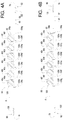
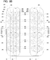
- the organizer axes A are depicted as linear Figures 2B , 4A, and 4B , but it should be understood that one or more of the organizers 80, 82, and/or 84 may be made of flexible material, in which case the organizer axes A defined thereby can and likely will be curved to define one or more localized points of inflexion along the organizer axis A during normal operation of the first example round sling system 20.
- the organizers 80, 82, and 84, and the cover member 60 to which the organizers 80, 82, and 84 are attached should have sufficient rigidity to prevent the bearing structure 30 from deforming such that the bearing positions 42 do not completely overlap during normal use of first example round sling system 20.
- the example closure system 64 secures the first side edge 74 to the second side edge 76 to hold the cover member 60 in a closed configuration to form the cover chamber 78.
- the example first and second edge connectors 90 and 92 extend along the entire lengths of the side edges 74 and 76, but alternative connector systems may be arranged only at spaced locations along the side edges 74 and 76 as will be described below.
- a similar connector (not shown) may be arranged to join the first and second end edges 70 and 72, but simply providing sufficient overlap between the first and second end edges 70 and 72 may be effective at holding the cover member 60 in its closed configuration to define the cover chamber 78.
- the cover member 60 is held in its closed configuration with the bearing structure 30 within the cover chamber 78.
- the organizers 80, 82, and 84 are arranged to maintain the bearing structure 30 in a desired relationship with the cover assembly member 60 and also such that the individual loop portions 40 are held within the bearing positions 42.
- the first end organizers 80a and 80b are close enough to each other and the second end organizers 82a and 82b are close enough to each other to ensure that longitudinal axes of the loop portions 40 are substantially aligned at the first and second end portions 50 and 52 for desired engagement with the structural members 22 and 24, respectively.
- the organizer axes A of the first and second first organizers 80a and 80b would be substantially linear to ensure that each of the loop portions 40 bears on the linear bar without overlapping another loop portion 40 (see, e.g., 2A).
- the organizer axes A of the first and second first organizers 80a and 80b would be sufficiently curved to ensure that each of the loop portions 40 bears on the curved member but without overlapping another loop portion 40.
- the example organizers 84a and 84b each comprises an organizer member 120 secured to the cover member 60 to define organizer openings 122.
- the example organizer members 120 are sewn to the cover member 60 by threads 124.
- Alternative securing systems and methods such as snap fasteners, adhesives, hook and loop fasteners, or the like may be used to secure the organizer member 120 to the cover member 60.
- the example organizer system 62 employs seven threads 124a, 124b, 124c, 124d, 124e, 124f, and 124g to define six of the organizer openings 122a, 122b, 122c, 122d, 122e, and 122f.
- the six organizer openings 122a, 122b, 122c, 122d, 122e, and 122f correspond to the six example bearing positions 42a, 42b, 42c, 42d, 42e, and 42f, respectively.
- the six loop portions 40a, 40b, 40c, 40d, 40e, and 40f are partly arranged within the six organizer openings 122a, 122b, 122c, 122d, 122e, and 122f, respectively.
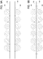
- Figures 2A , 2B , 3A , 4A, and 4B illustrate that the example first edge connector 90 is formed by a loop fastener 130 and the example second edge connector 92 is formed by a hook fastener 132.
- the hook fastener 132 engages loop fastener 130 to secure the first side edge 74 to the second side edge 76 along substantially the entire length of the first and second side edges 74 and 76.
- Other longitudinal fasteners such as zippers or the like may be used in place of the hook and loop fastener of the example closure system 64.
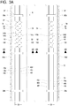
- Figure 3A further illustrates that the example bearing structure 30 is a single length of rope defining a splice region 140.
- the rope forming the example bearing structure 30 is arranged relative to the cover member 60 such that the example splice region 140 lies in one of the side portions 54 and 56 (in this case the second side portion 56) of the first example round sling system 20 rather than one of the end portions 50 or 52.
- Figure 3A illustrates that the loop portions 40 formed by the example bearing structure 30 cross at one or more crossing points 142.
- the example loop portions 40a, 40b, 40c, 40d, 40e, and 40f cross at first, second, third, fourth, and fifth crossing points 142a, 142b, 142c, 142d, and 142e.
- the first, second, and third crossing points 142a, 142b, and 142c are within the first side portion 54, while the fourth and fifth crossing points 142d and 142e are within the second side portion 56.
- first, second, and third crossing points 142a, 142b, and 142c are between the first first end organizer 80a and the first intermediate organizer 84a, while the fourth and fifth crossing points 142d and 142e are between the second first organizer 80b and the fourth intermediate organizer 84d.
- This arrangement further allows the loop portion 40a containing the splice region 140 to be straight and not overlap another loop portion 40 and eliminates the crossing of one loop portion 40 over multiple other loop portions 40.
- all crossing of any two (or possibly more) loop portions 40 should be within one of the side portions 54 and 56 and not within one of the end portions 50 or 52.
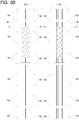
- Figure 3B illustrates a second example closure system 150 comprising a plurality of snap fasteners arranged at spaced locations along the first and second side edges 74 and 76.
- the example closure system 150 comprises a plurality of snap buttons 152 each arranged to engage one of a plurality of snap receivers 154. The mechanically engaging the snap buttons 152 with the snap receivers 154, the first and second side edges 74 and 76 are effectively secured together to form the cover chamber 78.
- Figure 3C illustrates a second example bearing structure 160 that may be used in place of the example bearing structure 30 formed by a single piece of looped rope.
- the second example bearing structure 160 comprises first, second, third, fourth, fifth, and sixth ropes 162a, 162b, 162c, 162d, 162e, and 162f defining first, second, third, fourth, fifth, and sixth splice regions 164a, 164b, 164c, 164d, 164e, and 164f. With each loop portion 40 formed by a single length of rope 162, crossing of loop portions 40 is eliminated.
- Figure 3D illustrates that the second example closure system 150 may be combined with the second example bearing structure 160.
- the second organizer type 170 comprises a first organizer member 172 secured to a second organizer member 174 to define the organizer openings 122.
- the example first organizer member 172 is sewn to the second organizer member 174 by threads 176, and the second organizer member 174 is sewn to the cover member 60 by threads 178, but other securing systems and methods such as snap fasteners, adhesives, hook and loop fasteners, or the like may be used to secure the first organizer 172 to the second organizer 174 and/or the second organizer member 174 to the cover member 60.
- the third organizer type 180 comprises a first organizer member 182 secured to a second organizer member 184 to define the organizer openings 122.
- the example first organizer member 182 is secured to the second organizer member 184 by bayonet members 186a that are received by bayonet openings 186b.
- the example second organizer member 184 is sewn to the cover member 60 by threads 188.
- Alternative securing systems and methods such as snap fasteners, adhesives, hook and loop fasteners, or the like may be used to secure the first organizer 182 to the second organizer 184 and/or the second organizer member 184 to the cover member 60.
- FIG. 7 depicted therein is a second example round sling system 220 constructed in accordance with, and embodying, the principles of the present invention.
- the second example round sling system 220 is adapted to transfer loads between a first structural member (not shown) and a second structural member (not shown).
- the second example round sling system 220 comprises a bearing structure 230 and a cover assembly 232.
- the example bearing structure 230 comprises one or more lengths of rope configured to bear the anticipated transfer loads applied to the second example round sling system 220.
- the example bearing structure 230 comprises a single piece of rope arranged in one or more loops 240 to define a plurality of bearing positions 242.
- the rope forming the example bearing structure 230 is configured to define 12 loops arranged in twelve bearing positions.
- the bearing structure 230 defines a first end portion 250, a second end portion (not visible in Figure 7 ), a first side portion 254, and a second side portion 256 of the first example rope sling 220.
- the example cover assembly 232 comprises a cover member 260, an organizer system 262, and a closure system 264.
- the example cover member 260 is a flat sheet of flexible material such as fabric defining a first end edge 270, a second end edge 272, a first side edge 274, and a second side edge 276.
- the example cover member 260 is capable of being folded or wrapped into a toroidal shape by overlapping the first and second end edges 270 and 272 and the first and second side edges 274 and 276.
- the cover member 260 defines a cover chamber 278.
- the example cover chamber 278 is substantially toroidal. In use, the substantially toroidal shape of the cover chamber 278 is typically elongated as shown in Figure 1 .
- the example organizer system 262 comprises at least one first end organizer 280, at least one second end organizer (not shown), and, optionally, one or more intermediate organizers 282.
- the example closure system 264 comprises a first edge connector 290 and a second edge connector 292.
- bearing structure 230 is arranged within the cover chamber 278, and the bearing structure 230 and the cover assembly 232 are arranged in an elongate loop as shown in Figure 1 .
- the elongate loop so formed defines the first end portion 250, the second end portions, and the first and second side portions 254 and 256 of the second example round sling system 220.
- the first end organizers 280 are secured to the cover member 260 such that the first end organizers 280 are adjacent to the first end 250, while the second end organizers (not shown) are secured to the cover member 260 such that the second end organizers are adjacent to the second end (not shown).
- the intermediate organizers 282 are spaced between the first end portion 250 and the second end portion (not shown) and are secured to the first and second side portions 254 and 256.
- the first and second first end organizers 280a and 280b are arranged at each end of the first end portion 250, while first and second second end organizers are arranged at each end of the second end portion.
- the intermediate organizers 282 are arranged at evenly spaced locations along the first and second side portions 254 and 256.
- the organizers 280 and 282 are configured to hold the loops defined by the rope forming the bearing structure 220 in the appropriate bearing positions 242 relative to the cover assembly 232.
- the example bearing positions 242 are arranged in a grouping such that the longitudinal axes defining six of the loop portions 240 are substantially parallel to and spaced from each other along a first organizer axis A1 and six of the loop portions 240 are substantially parallel to and spaced from each other along a second organizer axis A2.
- the first and second axes A1 and A2 defined by the first end organizers 280a and 280b arrange the loop portions 240 in two stacked groups 286 and 288.
- the end organizers 280a and 280b maintain these stacked groups 286 and 288 throughout the first end portion 250 to control the transfer of loads from the first structural member to the bearing structure 230.
- the organizer axes A1 and A2 are depicted as linear in Figure 8B , but it should be understood that one or more of the end organizers or intermediate organizers may be made of flexible material, in which case the organizer axes A1 and A2 defined thereby can and likely will be curved to define one or more localized points of inflexion along the organizer axes A1 and A2 during normal operation of the second example round sling system 220.
- the end and intermediate organizers 280 and 282, and the cover member 260 to which the organizers 280 and 282 are attached should have sufficient rigidity to prevent the bearing structure 230 from deforming such that the bearing positions 242 do not completely overlap during normal use of second example round sling system 220.
- the example closure system 264 secures the first side edge 274 to the second side edge 276 to hold the cover member 260 in a closed configuration to form the cover chamber 278.
- the example first and second edge connectors 290 and 292 extend along the entire lengths of the side edges 274 and 276, but alternative connector systems may be arranged only at spaced locations along the side edges 274 and 276 as will be described below.
- a similar connector (not shown) may be arranged to join the first and second end edges 270 and 272, but simply providing sufficient overlap between the first and second end edges 270 and 272 may effectively hold the cover member 260 in its closed configuration to define the cover chamber 278.
- the cover member 260 is held in its closed configuration with the bearing structure 230 within the cover chamber 278.
- the end and intermediate organizers 280 and 282 are arranged to maintain the bearing structure 230 in a desired relationship with the cover assembly member 260 and also such that the individual loop portions 240 are held within the bearing positions 242.
- first end organizers 280a and 280b are close enough to each other and the second end organizers (not shown) are close enough to each other to ensure that longitudinal axes of the loop portions 240 are substantially aligned at the first end portion 250 and second end portion (not shown) for desired engagement with the structural members (not shown), respectively.
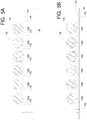
- Figures 9A and 9B illustrate one example structure of the example organizers 280 and 282 used with the second example round sling system 220.
- the example organizer structures may be formed by first and second base straps 320 and 322 and first and second loop straps 324 and 326.
- the first and second loop straps 324 and 226 are sewn to the first and second base straps 320 and 322, respectively.
- the first and second base straps 320 and 322 are then sewn to the cover member 260.
- the first and second loop straps 324 and 326 may be sewn directly to the cover 260 or to a single base strap that is in turn sewn to the cover.
- the loop straps may be secured to the base strap and/or the cover by other securing systems and methods such as hook and loop fasteners, adhesives, snap fasteners, or the like.
- longitudinal refers to the direction of a reference dimension defined by a dimension of a component that is longer than the dimensions of that component in the two directions orthogonal to the reference direction.
- parallel will be used herein to refer to localized longitudinal directions of two components being compared and does not indicate that the two component are parallel along their entire length.
- cross will be used with reference to a particular perspective to refer to one component overlapping or extending over another component.
Landscapes
- Engineering & Computer Science (AREA)
- Mechanical Engineering (AREA)
- Load-Engaging Elements For Cranes (AREA)
Claims (20)
- Rundschlingensystem (20, 220), umfassend:eine Tragestruktur (20, 30, 160, 220, 230), die zum Definieren einer Vielzahl von Schlaufenabschnitten (40, 240) eingerichtet ist, die in einer Vielzahl von Trageabschnitten (42, 242) eingerichtet sind, wobei die Tragestruktur (20, 30, 160, 220, 230) auch zum Definieren von mindestens einem Tragestruktur-Endabschnitt (50, 52, 250, 252) eingerichtet ist;eine Abdeckung (60, 260), die eine Abdeckkammer (78, 278) definiert;mindestens einen Ausrichter (80, 82, 84, 180, 182, 184, 280, 282),dadurch gekennzeichnet, dass der mindestens eine Ausrichter (80, 82, 84, 180, 182, 184, 280, 282) an der Abdeckung (60, 260) befestigt ist, um eine Vielzahl von Ausrichteröffnungen (122) zu definieren, wobei jede Ausrichteröffnung (122) der jeweiligen Trageposition (42, 242) entspricht, derart dass jeder Schlaufenabschnitt (40, 240) teilweise innerhalb der jeweiligen Ausrichteröffnung (122) eingerichtet ist, wobei der Ausrichter (80, 82, 84, 180, 182, 184, 280, 282) dadurch zum Eingreifen in die Tragestruktur (20, 30, 160, 220, 230) konfiguriert ist, derart dass der mindestens eine Ausrichter (80, 82, 84, 180, 182, 184, 280, 282) eine Position der Tragestruktur (20, 30, 160, 220, 230) relativ zur Abdeckung (60, 260) beibehält, undder mindestens eine Ausrichter (80, 82, 84, 180, 182, 184, 280, 282) eine räumliche Beziehung der Schlaufenabschnitte (40, 240) mindestens innerhalb des mindestens einen Tragestrukturendabschnitts (50, 52, 250, 252) aufrechterhält.
- Rundschlingensystem (20, 220) nach Anspruch 1, wobei:die Tragestruktur (20, 30, 160, 220, 230) erste und zweite Tragestruktur-Endabschnitte (50, 52, 250, 252) definiert; undmindestens ein Ausrichter (80, 82, 84, 180, 182, 184, 280, 282) an der Abdeckung (60, 260) jeweils an den ersten und den zweiten Tragestruktur-Endabschnitt (50, 52, 250, 252) anschließend befestigt ist.
- Rundschlingensystem (20, 220) nach Anspruch 1, wobei:die Tragestruktur (20, 30, 160, 220, 230) erste und zweite Tragestruktur-Endabschnitte (50, 52, 250, 252) definiert; undein Paar von Ausrichtern (80, 82, 84, 180, 182, 184, 280, 282) an der Abdeckung (60, 260) jeweils an die ersten und zweiten Tragestruktur-Endabschnitte (50, 52, 250, 252) befestigt ist.
- Rundschlingensystem (20, 220) nach Anspruch 1, wobei:das Abdeckelement (60, 260) erste und zweite Endrandabschnitte der Abdeckung definiert; undder erste und zweite Abdeckungsendabschnitt sich an einer Stelle überlappen, die von dem mindestens einen Tragwerksendabschnitt (50, 52, 250, 252) beabstandet ist.
- Rundschlingensystem (20, 220) nach Anspruch 1, wobei:das Abdeckelement (60, 260) erste und zweite Abdeck-Seitenrandabschnitte und erste und zweite Abdeck-Endrandabschnitte definiert; unddie ersten und zweiten Abdeck-Endabschnitte (50, 52, 250, 252) zwischen den ersten und zweiten Abdeck-Endrandabschnitten überlappen.
- Rundschlingensystem (20, 220) nach Anspruch 5, wobei die ersten und zweiten Abdeck-Endabschnitte an einer Stelle überlappen, die von dem mindestens einen Tragestruktur-Endabschnitt (50, 52, 250, 252) beabstandet ist.
- Rundschlingensystem (20, 220) nach Anspruch 1, wobei:die Tragestruktur (20, 30, 160, 220, 230) erste und zweite Tragestruktur-Endabschnitte (50, 52, 250, 252) und erste und zweite Tragestruktur-Seitenabschnitte definiert; undmindestens ein Ausrichter (80, 82, 84, 180, 182, 184, 280, 282) an der Abdeckung (60, 260) jeweils innerhalb der ersten und zweiten Tragestruktur-Seitenteile befestigt ist.
- Rundschlingensystem (20, 220) nach Anspruch 2, wobei:die Tragestruktur (20, 30, 160, 220, 230) ferner erste und zweite Tragestruktur-Seitenabschnitt definiert; undmindestens ein Ausrichter (80, 82, 84, 180, 182, 184, 280, 282) an der Abdeckung (60, 260) jeweils mit den ersten und zweiten Tragestruktur-Seitenteile befestigt ist.
- Rundschlingensystem (20, 220) nach Anspruch 1, das ferner ein Verschlusssystem (64, 150, 264) zum Feststellen der Abdeckung (60, 260) in einer geschlossenen Konfiguration umfasst.
- Verfahren zum Bilden einer Rundschlinge, das die folgenden Schritte umfasst:Einrichten einer Tragestruktur (20, 30, 160, 220, 230), um eine Vielzahl von Schlaufenabschnitten (40, 240) zu definieren;Bereitstellen einer Abdeckung (60, 260) und Einrichten der Abdeckung (60, 260) zur Definition einer Abdeckkammer (78, 278), derart dass sich die tragende Struktur (20, 30, 160, 220, 230) innerhalb der Abdeckkammer (78, 278) befindet;Bereitstellen mindestens eines Ausrichters (80, 82, 84, 180, 182, 184, 280, 282);gekennzeichnet durchBefestigen des mindestens einen Ausrichters (80, 82, 84, 180, 182, 184, 280, 282) an der Abdeckung (60, 260), um eine Vielzahl von Ausrichteröffnungen (122) zu definieren, derart dass jede Ausrichteröffnung (122) der jeweiligen Trageposition (42, 242) entspricht und jeder Schlaufenabschnitt (40, 240) teilweise innerhalb der jeweiligen Ausrichteröffnung (122) eingerichtet ist, dementsprechend der mindestens eine Ausrichter (80, 82, 84, 180, 182, 184, 280, 282) zum Eingriff in die Tragestruktur (30, 160) konfiguriert, derart dass der mindestens eine Ausrichter (80, 82, 84, 180, 182, 184, 280, 282) eine Position von mindestens einem Abschnitt der Tragestruktur (20, 30, 160, 220, 230) relativ zu der Abdeckung (60, 260) beibehält; undder mindestens eine Ausrichter (80, 82, 84, 180, 182, 184, 280, 282) eine räumliche Beziehung der Schlaufenabschnitte (40, 240) mindestens innerhalb von mindestens einem Tragestruktur-Endabschnitt (50, 52, 250, 252), der durch die Tragestruktur (20, 30, 160, 220, 230) definiert ist, aufrechterhält.
- Verfahren nach Anspruch 10, wobei:die Tragestruktur (20, 30, 160, 220, 230) erste und zweite Tragestruktur-Endabschnitte (50, 52, 250, 252) definiert, wenn sie sich innerhalb der Abdeckkammer (78, 278) befindet; undder Schritt des Befestigens von mindestens einem Ausrichter (80, 82, 84, 180, 182, 184, 280, 282) an dem Abdeckelement (60, 260) den Schritt des Befestigens von mindestens einem Ausrichter (80, 82, 84, 180, 182, 184, 280, 282) an der Abdeckung (60, 260) jeweils anschließend an die ersten und zweiten Tragestruktur-Endabschnitte (50, 52, 250, 252) umfasst.
- Verfahren nach Anspruch 10, wobei:die Tragestruktur (20, 30, 160, 220, 230) erste und zweite Tragestruktur-Endabschnitte (50, 52, 250, 252) definiert, wenn sie sich innerhalb der Abdeckkammer (78, 278) befindet; undder Schritt des Befestigens von mindestens einem Ausrichter (80, 82, 84, 180, 182, 184, 280, 282) an dem Abdeckelement (60, 260) den Schritt des Befestigens eines Paares von Ausrichtern (80, 82, 84, 180, 182, 184, 280, 282) an der Abdeckung (60, 260) jeweils anschließend an die ersten und zweiten Tragestruktur-Endabschnitte (50, 52, 250, 252) umfasst.
- Verfahren nach Anspruch 10, wobei:das Abdeckungselement (60, 260) erste und zweite Abdeck-Endrandabschnitte definiert; undder Schritt des Einrichtens der Abdeckung (60, 260), um eine Abdeckkammer (78, 278) zu definieren, den Schritt des Überlappens der ersten und zweiten Abdeck-Endabschnitte an einer Stelle umfasst, die von dem mindestens einen Tragestruktur-Endabschnitt (50, 52, 250, 252) beabstandet ist.
- Verfahren nach Anspruch 10, wobei:das Abdeckelement (60, 260) erste und zweite Abdeck-Seitenrandabschnitte und erste und zweite Abdeck-Endrandabschnitte definiert; undder Schritt des Einrichtens der Abdeckung (60, 260) zum Definieren einer Abdeckkammer (78, 278) den Schritt des Überlappens der ersten und zweiten Abdeck-Endabschnitte zwischen den ersten und zweiten Abdeck-Endrandabschnitten umfasst.
- Verfahren nach Anspruch 14, wobei der Schritt des Einrichtens der Abdeckung (60, 260), um eine Abdeckkammer (78, 278) zu definieren, den Schritt des Überlappens der ersten und zweiten Abdeck-Endabschnitte an einer Stelle umfasst, die von dem mindestens einen Tragestruktur-Endabschnitt (50, 52, 250, 252) beabstandet ist.
- Ein Verfahren nach Anspruch 10, wobei:die Tragestruktur (20, 30, 160, 220, 230) erste und zweite Tragestruktur-Endabschnitte (50, 52, 250, 252) und erste und zweite Tragestruktur-Seitenabschnitte definiert; undder Schritt des Einrichtens des mindestens einen Ausrichters (80, 82, 84, 180, 182, 184, 280, 282) zum Eingreifen in die Tragestruktur (20, 30, 160, 220, 230) den Schritt des Befestigens von mindestens einem Ausrichter (80, 82, 84, 180, 182, 184, 280, 282) an der Abdeckung (60, 260) jeweils innerhalb der ersten und zweiten Tragestruktur-Seitenabschnitte umfasst.
- Verfahren nach Anspruch 11, wobei:die Tragestruktur ferner erste und zweite Tragestruktur-Seitenabschnitte definiert; undder Schritt des Einrichtens des mindestens einen Ausrichters (80, 82, 84, 180, 182, 184, 280, 282) zum Eingreifen in die Tragestruktur (20, 30, 160, 220, 230) den Schritt des Befestigens von mindestens einem Ausrichter (80, 82, 84, 180, 182, 184, 280, 282) an der Abdeckung (60, 260) jeweils innerhalb der ersten und zweiten Tragestruktur-Seitenabschnitte umfasst.
- Verfahren nach Anspruch 10, das ferner den Schritt des Befestigens der Abdeckung (60, 260) in einer geschlossenen Konfiguration umfasst.
- Rundschlingensystem (20, 220) nach Anspruch 1, wobei das Rundschlingensystem (20, 220) zum Eingriff in erste und zweite Strukturelementen ausgelegt ist,
wobei
die Tragestruktur (20, 30, 160, 220, 230) zur Definition von ersten und zweiten Tragestruktur-Endabschnitten (50, 52, 250, 252) und ersten und zweiten Tragestruktur-Seitenabschnitten eingerichtet ist;
die Abdeckung (60, 260) erste und zweite Abdeck-Endrandabschnitte und erste und zweite Abdeck-Seitenrandabschnitte umfasst;
wobei ein Sicherungssystem die Abdeckung (60, 260) konfiguriert, um eine Abdeckkammer (78, 278) zu definieren;
wobei der mindestens eine Ausrichter folgendes ist:ein erstes Paar von endständigen Ausrichtern (80, 180, 280), die an der Abdeckung (60, 260) befestigt sind;ein zweites Paar von endständigen Ausrichtern, die an der Abdeckung (60, 260) befestigt sind; undmindestens ein dazwischenliegenden Ausrichter (84, 184, 282), der an der Abdeckung (60, 260) befestigt ist; wobeidas erste Paar von endständigen Ausrichtern (80, 180, 280) sich auf der Abdeckung (60, 260) befindet, um in die Tragestruktur (20, 30, 160, 220, 230) neben dem ersten Tragestruktur-Endabschnitt (50, 52, 250, 252) einzugreifen;das zweite Paar von endständigen Ausrichtern sich an der Abdeckung (60, 260) befindet, um in die Tragestruktur (20, 30, 160, 220, 230) an den zweiten Tragestruktur-Endabschnitt (50, 52, 250, 252) anschließend einzugreifen;der mindestens eine dazwischenliegende Ausrichter (84, 184, 282) in die Tragestruktur (20, 30, 160, 220, 230) innerhalb von mindestens einem der ersten und zweiten Tragestruktur-Seitenabschnitte (54, 56, 254, 256) eingreift; unddas erste und zweite Paar von endständigen Ausrichtern eine räumliche Beziehung der Schlaufenabschnitte (40, 240) innerhalb der ersten und zweiten Tragestruktur (30, 160)-Endabschnitte (50, 52, 250, 252) aufrechterhält. - Rundschlingensystem (20, 220) nach Anspruch 19, wobei:die Abdeckung (60, 260) erste und zweite Abdeck-Endrandabschnitte und erste und zweite Abdeck-Seitenrandabschnitte umfasst;das Sicherungssystem die ersten und zweiten Abdeck-Seitenabschnitte so aneinander befestigt, dass die ersten und zweiten Seitenrandabschnitte nicht mit den ersten und zweiten Strukturelementen in Kontakt sind, unddie ersten und zweiten Endrandabschnitte angrenzend an einen der ersten und zweiten Tragestruktur-Seitenabschnitte überlappen.
Applications Claiming Priority (2)
| Application Number | Priority Date | Filing Date | Title |
|---|---|---|---|
| US201662330110P | 2016-04-30 | 2016-04-30 | |
| US15/498,180 US10377607B2 (en) | 2016-04-30 | 2017-04-26 | Rope systems and methods for use as a round sling |
Publications (2)
| Publication Number | Publication Date |
|---|---|
| EP3239090A1 EP3239090A1 (de) | 2017-11-01 |
| EP3239090B1 true EP3239090B1 (de) | 2021-01-06 |
Family
ID=58644973
Family Applications (1)
| Application Number | Title | Priority Date | Filing Date |
|---|---|---|---|
| EP17168853.4A Active EP3239090B1 (de) | 2016-04-30 | 2017-04-28 | Rundschlinge sowie herstellungsverfahren |
Country Status (2)
| Country | Link |
|---|---|
| US (1) | US10377607B2 (de) |
| EP (1) | EP3239090B1 (de) |
Families Citing this family (4)
| Publication number | Priority date | Publication date | Assignee | Title |
|---|---|---|---|---|
| US10377607B2 (en) | 2016-04-30 | 2019-08-13 | Samson Rope Technologies | Rope systems and methods for use as a round sling |
| RU2715062C1 (ru) * | 2019-06-28 | 2020-02-25 | Акционерное общество "Национальный центр вертолетостроения им. М.Л. Миля и Н.И. Камова" (АО "НЦВ Миль и Камов") | Способ и устройство для изготовления моноколец ленточных канатов |
| US11623847B2 (en) * | 2020-01-30 | 2023-04-11 | Cortland Company, Inc. | Sling |
| KR102662415B1 (ko) * | 2023-12-04 | 2024-04-29 | 천상동 | 섬유로프 라운드슬링 |
Family Cites Families (286)
| Publication number | Priority date | Publication date | Assignee | Title |
|---|---|---|---|---|
| US429174A (en) | 1890-06-03 | ogilvy | ||
| US568531A (en) | 1896-09-29 | Chain | ||
| US1168802A (en) | 1913-03-07 | 1916-01-18 | Roeblings John A Sons Co | Hoisting and similar sling. |
| US1257398A (en) | 1915-10-08 | 1918-02-26 | Christopher J Roach | Chain construction. |
| US1479865A (en) | 1923-06-18 | 1924-01-08 | Harold G Metcalf | Rope structure |
| US1490387A (en) | 1923-10-20 | 1924-04-15 | Christian L Hansen | Excavating apparatus |
| US1695480A (en) | 1926-10-30 | 1928-12-18 | G H Williams Company | Drag-line excavator |
| US1710740A (en) | 1926-12-20 | 1929-04-30 | Harnischfeger Corp | Hitch or clevis for dragline buckets |
| BE350461A (de) | 1928-04-30 | |||
| US1769945A (en) | 1929-01-25 | 1930-07-08 | William C Erkert | Wire rope or cable |
| US1908686A (en) | 1930-03-31 | 1933-05-16 | Northwest Engineering Corp | Dragline bucket |
| US1839698A (en) | 1930-11-14 | 1932-01-05 | John W Novotny | Cable splice |
| US1850767A (en) | 1930-12-27 | 1932-03-22 | John W Page | Spreader |
| US1833587A (en) | 1931-01-26 | 1931-11-24 | John W Page | Excavating shovel |
| US2070362A (en) | 1931-09-30 | 1937-02-09 | Felix Schull | Method of making chains |
| US1931808A (en) | 1931-11-24 | 1933-10-24 | Andersen Hans | Rope sling |
| US2074956A (en) | 1935-09-13 | 1937-03-23 | American Steel & Wire Co | Wire rope |
| US2080148A (en) | 1935-10-07 | 1937-05-11 | Macwhyte Company | Choker hook |
| US2142642A (en) | 1937-12-16 | 1939-01-03 | Macwhyte Company | Sling |
| US2245824A (en) | 1940-08-03 | 1941-06-17 | Eraser Company Inc | Method of manufacturing glass rope |
| US2299568A (en) | 1941-02-03 | 1942-10-20 | Broderick & Bascom Rope Compan | Sling |
| US2359424A (en) | 1942-09-21 | 1944-10-03 | Bethlehem Steel Corp | Rope sling |
| US2338831A (en) | 1943-01-09 | 1944-01-11 | Harry A Whitcomb | Dragline bucket |
| US2480005A (en) | 1945-12-19 | 1949-08-23 | Don P Gavan | Wire rope |
| US2413642A (en) | 1946-05-10 | 1946-12-31 | Leschen & Sons Rope Company A | Method of forming loops |
| US2454592A (en) | 1948-01-31 | 1948-11-23 | Budzinski Joseph | Cable eye and method of splicing the same |
| US2482204A (en) | 1948-02-10 | 1949-09-20 | American Chain & Cable Co | Wire rope splice |
| US2960365A (en) | 1956-01-17 | 1960-11-15 | Meisen Hans | Lifting sling composed of steel cables |
| US2840983A (en) | 1956-04-23 | 1958-07-01 | Paul C Keilbach | Resiliently coiled chain constructions and links therefor |
| US3073209A (en) | 1959-01-16 | 1963-01-15 | Glanzstoff Ag | Mountaineering ropes of core-mantle structure |
| US3035476A (en) | 1961-02-23 | 1962-05-22 | Samson Cordage Works | Braided cord |
| US3181907A (en) | 1962-08-09 | 1965-05-04 | O'donnell Mabel | Rope slings |
| FR90038E (fr) | 1963-05-13 | 1967-09-29 | Alsace Lorraine Cableries | élingue plate à une ou plusieurs nappes de câbles en acier |
| DE1585542A1 (de) | 1964-02-14 | 1972-03-02 | P G Holm Ab Oy | Band zum Heben und/oder Umbinden von Gegenstaenden |
| US3295303A (en) | 1964-09-28 | 1967-01-03 | Beveridge Levi Clark | Rope-splicing device |
| US3371476A (en) | 1965-04-02 | 1968-03-05 | Gen Motors Corp | Glass plastic rope |
| US3358434A (en) | 1965-07-16 | 1967-12-19 | Tubbs Cordage Company | Low elongation synthetic rope |
| US3415052A (en) | 1966-04-12 | 1968-12-10 | American Mfg Company Inc | Synthetic plastic rope for automatic devices |
| US3383849A (en) | 1966-08-10 | 1968-05-21 | Stirling James | Rope strand or yarn and method of making same to reduce its whip-back characteristic at rupture |
| FR1500314A (fr) | 1966-09-20 | 1967-11-03 | Rhodiaceta | Boucle épissée et procédé pour la réaliser |
| JPS469565Y1 (de) | 1967-04-03 | 1971-04-05 | ||
| JPS4625320Y1 (de) * | 1967-04-28 | 1971-09-01 | ||
| US3367095A (en) | 1967-06-30 | 1968-02-06 | Du Pont | Process and apparatus for making wrapped yarns |
| US3425737A (en) | 1967-08-28 | 1969-02-04 | Jimmy E Sutton | Pipe sling |
| US3481134A (en) | 1968-01-19 | 1969-12-02 | Warner Swasey Co | Method of making multistrand textile cord |
| US3507949A (en) | 1968-06-11 | 1970-04-21 | British Ropes Ltd | Method of socketing strands |
| US3524690A (en) | 1968-07-01 | 1970-08-18 | Ruth Marilene Gurney | Hygiene kit and case |
| US3583749A (en) | 1968-07-05 | 1971-06-08 | John C Hopkins | Rope assembly |
| USRE26704E (en) | 1968-12-03 | 1969-11-04 | Norton fabric load lifting sling | |
| US3537742A (en) | 1969-01-31 | 1970-11-03 | Boyd C Black | Lift sling construction |
| GB1292055A (en) | 1969-03-11 | 1972-10-11 | Courtaulds Ltd | Novelty textile yarns |
| US3561318A (en) | 1969-05-14 | 1971-02-09 | Wellington Puritan Mills Inc | Elongated braided rope and method for producing the same |
| US3904458A (en) | 1969-07-16 | 1975-09-09 | Ici Ltd | Method of joining continuous strands |
| BE757296A (fr) | 1969-10-13 | 1971-03-16 | Brindejonc De Treglode Pierre | Element de support ou de traction, en particulier pour elingueset son procede de fabrication |
| US3662533A (en) | 1970-01-05 | 1972-05-16 | Norfin | Glass fiber cable |
| US3653295A (en) | 1970-04-30 | 1972-04-04 | Johns Manville | Method of providing a lubricant to braided cord |
| US3839207A (en) | 1971-04-30 | 1974-10-01 | Stauffer Chemical Co | Allyl 2-carbamoyalkylphosphonates flame retardants |
| US3762865A (en) | 1971-04-30 | 1973-10-02 | Stauffer Chemical Co | Flame retarding of solid substrates with allyl 2-carbamoylalkylphosphonates |
| US3906136A (en) | 1971-04-30 | 1975-09-16 | Stauffer Chemical Co | Process of flame retarding substrates by applying hexahydratriazine phosphonate derivatives |
| US3915618A (en) | 1972-02-10 | 1975-10-28 | Goodyear Tire & Rubber | Apparatus for making hose |
| US3771305A (en) | 1972-06-15 | 1973-11-13 | Johns Manville | Fiber glass groove packing |
| FR2197392A5 (en) | 1972-08-24 | 1974-03-22 | Kersaudy Et Lem Ur Ets | Cable comprising tubular sheath around floatable core - is easily handleable and floats uniformly |
| DE7315621U (de) | 1972-08-29 | 1973-10-04 | Sunne Gummifabrik Ab | Schlepp- und festmachetau |
| SU436115A1 (ru) | 1973-01-16 | 1974-07-15 | В. Р. Любимов | Способ изготовления канатных петель |
| DE2332198A1 (de) | 1973-06-25 | 1975-02-06 | Alfons Walz | Vorrichtung zum abbauen und hochfoerdern von am meeresboden abgelagertem schuettgut wie erzknollen, mineralseifen und erzschlaemme |
| US3957923A (en) | 1973-06-25 | 1976-05-18 | E. I. Du Pont De Nemours & Company | Alkyl and haloalkyl n,n'-dialkyl-n-methylolphosphorodiamidates |
| US3854767A (en) | 1973-08-31 | 1974-12-17 | Burnett Co Ltd | Rope assembly |
| NO131848C (de) | 1974-03-21 | 1975-08-13 | Pusnes Mek Verksted | |
| US4173113A (en) | 1974-05-02 | 1979-11-06 | Norfin, Inc. | Thermally stable helically plied cable |
| US3979545A (en) | 1974-09-12 | 1976-09-07 | National Distillers And Chemical Corporation | Synthetic fiber impregnated with flame retardant compositions containing halogen containing amides |
| US3968725A (en) | 1974-12-13 | 1976-07-13 | Berkley & Company, Inc. | High strength, low stretch braided rope |
| US3977172A (en) | 1975-02-06 | 1976-08-31 | E. I. Du Pont De Nemours And Company | Reinforcement cord |
| US4050230A (en) | 1975-02-24 | 1977-09-27 | Ube Nitto Kasei Co., Ltd. | Rope |
| US4195113A (en) | 1975-03-12 | 1980-03-25 | Desoto, Inc. | Encapsulated impregnated rovings |
| NL7510815A (nl) | 1975-09-15 | 1977-03-17 | Robert De Vries Valeriusstraat | Schakelketting, en een voor het vormen van een schakel daarvan te gebruiken inrichting. |
| US4036101A (en) | 1975-12-01 | 1977-07-19 | The Burnett Company, Ltd. | Double hollow braided rope assembly and method |
| GB1524990A (en) | 1975-12-24 | 1978-09-13 | Spanset Inter Ag | Lifting slings and a method for producing same |
| US4022507A (en) | 1976-03-17 | 1977-05-10 | Marino Systems, Inc. | Self-cinching cargo sling |
| US4045072A (en) | 1976-05-18 | 1977-08-30 | United Technology, Inc. | Abrasion resistant boot |
| US4031121A (en) | 1976-09-22 | 1977-06-21 | Dow Corning Corporation | Organobromosilicone fluids |
| US4114360A (en) | 1977-05-09 | 1978-09-19 | Johnny Dale Emmons | Pigging string and method of manufacture |
| US4155394A (en) | 1977-08-29 | 1979-05-22 | The Goodyear Tire & Rubber Company | Tire cord composite and pneumatic tire |
| US4099750A (en) | 1977-09-02 | 1978-07-11 | Mcgrew James D | Method of forming eye splice in double braided line |
| CA1077088A (en) | 1977-09-07 | 1980-05-06 | Svensk Lasthantering Lindahl (Bengt) Ab | Roundsling |
| JPS5461001A (en) | 1977-10-25 | 1979-05-17 | Saito Chiyuuji | Continuously sampling apparatus of ore of sea bottom |
| GB2011969B (en) | 1977-11-11 | 1982-04-07 | Cable Belt Ltd | Ropes and the like |
| US4257221A (en) | 1977-11-21 | 1981-03-24 | Feinberg Arthur L | Fire resistant fiber blend |
| US4159618A (en) | 1978-03-13 | 1979-07-03 | Albany International Corp. | Composite yarn |
| US4170921A (en) | 1978-03-17 | 1979-10-16 | New England Ropes, Inc. | Braided rope |
| US4286429A (en) | 1978-04-14 | 1981-09-01 | Lin Spencer B T | Polypropylene endless loop and the method therefor |
| US4232619A (en) | 1978-04-25 | 1980-11-11 | Svensk Lasthantering, Bengt Lindahl Ab | Lifting loop |
| DE2818386C2 (de) | 1978-04-27 | 1982-03-11 | Fröhlich & Wolff GmbH, 3436 Hessisch-Lichtenau | Garn aus einem multifilen, synthetischen, polymeren Material und Verfahren zur Veredelung eines derartigen Garns |
| US4184784A (en) | 1978-07-03 | 1980-01-22 | The Bendix Corporation | Termination and method of terminating ropes or cables of aramid fiber or the like |
| FR2436841A1 (fr) | 1978-09-22 | 1980-04-18 | Rhone Poulenc Textile | Nouveau type de cordage, cable et procede pour sa fabrication |
| US4228641A (en) | 1978-09-28 | 1980-10-21 | Exxon Research & Engineering Co. | Thermoplastic twines |
| US4202164A (en) | 1978-11-06 | 1980-05-13 | Amsted Industries Incorporated | Lubricated plastic impregnated aramid fiber rope |
| US4232903A (en) | 1978-12-28 | 1980-11-11 | Lockheed Missiles & Space Co., Inc. | Ocean mining system and process |
| US4258608A (en) | 1979-02-14 | 1981-03-31 | Brown John L | In-line snubber for use with braided cordage |
| US4350380A (en) | 1979-03-27 | 1982-09-21 | Williams William C | Load carrying slings |
| US4321854A (en) | 1979-06-01 | 1982-03-30 | Berkley & Company, Inc. | Composite line of core and jacket |
| GR73539B (de) | 1980-01-21 | 1984-03-12 | Spanset Inter Ag | |
| US4329794A (en) | 1980-03-24 | 1982-05-18 | Dresser Industries, Inc. | Ripping attachment for dragline |
| JPS5748291U (de) | 1980-08-29 | 1982-03-18 | ||
| US4500593A (en) | 1980-12-01 | 1985-02-19 | Weber John W | Protective fabric and fire curtain with a metallic laminate |
| US4403884A (en) | 1981-03-18 | 1983-09-13 | Florida Wire And Cable Company | Wire assemblies for repetitive, continuous cycle, tensile load conditions, particularly sucker rods for oil wells |
| JPS57161116A (en) | 1981-03-30 | 1982-10-04 | Nippon Tokushu Kento Kk | Preparation of fiber for buff |
| US4375779A (en) | 1981-04-24 | 1983-03-08 | Minnesota Mining And Manufacturing Company | Composite sewing thread of ceramic fibers |
| US4414799A (en) | 1982-04-12 | 1983-11-15 | Louis Alexander | Rope splicer |
| US4563869A (en) | 1982-05-17 | 1986-01-14 | American Manufacturing Company, Inc. | Rope with reduced lash-back construction |
| US4534262A (en) | 1983-04-01 | 1985-08-13 | The United States Of America As Represented By The Secretary Of The Navy | Safety mooring line |
| US4509233A (en) | 1983-06-15 | 1985-04-09 | Esmet, Inc. | Rope clamp construction |
| US4534163A (en) | 1983-09-19 | 1985-08-13 | New England Ropes, Inc. | Rope or cable and method of making same |
| US4464812A (en) | 1983-10-24 | 1984-08-14 | The Crosby Group, Inc. | Socket for structural strand |
| US4640179A (en) | 1984-06-25 | 1987-02-03 | Cameron Robert W | Composite metallic core line |
| JPS6128092A (ja) | 1984-07-11 | 1986-02-07 | 東京製綱繊維ロ−プ株式会社 | 複合線条体およびその製造方法 |
| US4606183A (en) | 1984-11-20 | 1986-08-19 | Amsted Industries Incorporated | Lubricated and thermoplastic impregnated wire rope |
| US4635989A (en) | 1984-12-18 | 1987-01-13 | Tekna Recherche & Developpement Inc. | Cable clamping device |
| US4674801A (en) | 1985-02-06 | 1987-06-23 | Allied Corporation | Energy absorber having a limited stroke |
| US4642854A (en) | 1985-03-18 | 1987-02-17 | Southwest Wire Rope, Inc. | Socket for mounting on the end of a steel cable |
| US4762583A (en) | 1985-03-27 | 1988-08-09 | Kaempen Charles E | Method for making composite twine structures |
| US4619108A (en) | 1985-04-19 | 1986-10-28 | Amikan Fishing Net Mfg. Co., Ltd. | Multiple strand twines comprising monofilaments and multiple filaments, and fishnets formed thereof |
| US4779411A (en) | 1985-12-02 | 1988-10-25 | Link Enterprises Corporation | Flexible, non-metallic rigging chain |
| US4978360A (en) | 1986-03-03 | 1990-12-18 | Zimmer, Inc. | Method of manufacturing a composite implant prosthesis |
| DE3616465C1 (de) * | 1986-05-15 | 1987-05-14 | Heinz Franke | Rundschlinge zum Heben von Lasten |
| FR2599762B1 (fr) | 1986-06-04 | 1988-12-02 | Gosse Filature | Fil textile resistant au feu et utilisation de ce fil |
| US5240769A (en) | 1986-11-25 | 1993-08-31 | Nippon Pillar Packing Co. Ltd. | Packing material and packing made of the same |
| JPS63196741A (ja) | 1987-02-09 | 1988-08-15 | 東洋紡績株式会社 | 熱防護用布帛 |
| US4784918A (en) | 1987-03-30 | 1988-11-15 | Ppg Industries, Inc. | Compositions and coatings of phosphorus-containing film formers with organo silane and coated substrates |
| US4850629A (en) | 1988-02-04 | 1989-07-25 | St Germain Dennis | Multiple path sling construction |
| US4856837A (en) | 1988-02-16 | 1989-08-15 | Woven Electronics Corporation | Reinforced cargo sling and method |
| EP0333434B1 (de) | 1988-03-15 | 1993-08-18 | Sumitomo Rubber Industries Limited | Radialer Luftreifen für Motorräder |
| US4887422A (en) | 1988-09-06 | 1989-12-19 | Amsted Industries Incorporated | Rope with fiber core and method of forming same |
| JPH0686718B2 (ja) | 1988-10-31 | 1994-11-02 | 東京製綱株式会社 | 複合撚合型線条体の製造方法 |
| FR2640192B1 (fr) | 1988-12-12 | 1991-02-01 | Alsace Lorraine Sa Cableries | Procede de fabrication d'une elingue ou sangle plate de manutention, dont la nappe de brins de cables est enrobee dans un elastomere de polyurethane, et elingue ou sangle ainsi obtenue |
| US4958485A (en) | 1988-12-22 | 1990-09-25 | Springs Industries, Inc. | Corespun yarn for fire resistant safety apparel |
| DE68915722T2 (de) | 1988-12-28 | 1995-01-12 | Ube Nitto Kasei Co | Verdrillte faserverstärkte Kunststoffstruktur und Verfahren zu ihrer Herstellung. |
| JPH02210071A (ja) | 1989-02-10 | 1990-08-21 | Teijin Ltd | 繊維構造物 |
| US5091243A (en) | 1989-04-04 | 1992-02-25 | Springs Industries, Inc. | Fire barrier fabric |
| US5211500A (en) | 1989-04-06 | 1993-05-18 | Tokyo Rope Mfg. Co., Ltd. | Composite rope having molded-on fixing member at end portion thereof |
| SU1647183A1 (ru) | 1989-05-31 | 1991-05-07 | Ж, М. Касылкасов | Цепь |
| US5506043A (en) | 1989-08-18 | 1996-04-09 | Norfab Corporation | Thermal protective fabric and core-spun heat resistant yarn for making the same, said yarns consisting essentially of a fiberglass core and a cover of modacrylic fibers and at least one other flame retardant fiber |
| SU1723004A1 (ru) | 1989-08-24 | 1992-03-30 | Всесоюзный Научно-Исследовательский Институт По Монтажным И Специальным Строительным Работам | Строп |
| US4974488A (en) | 1989-12-11 | 1990-12-04 | Boris Spralja | Rope slicing apparatus and method |
| RU1791325C (ru) | 1990-03-23 | 1993-01-30 | э.Н.Байбородов и А.А.Шостак | Ленточный строп |
| US5022780A (en) | 1990-05-03 | 1991-06-11 | Esmet, Inc. | End clamp for textile rope with a metallic core |
| US5199253A (en) | 1990-07-16 | 1993-04-06 | American Manufacturing Company, Inc. | Nylon rope having superior friction and wearing resistance |
| USD342215S (en) | 1990-08-03 | 1993-12-14 | M G Z S.P.A. | Ornamental chain |
| US5296292A (en) | 1990-09-04 | 1994-03-22 | W. L. Gore & Associates, Inc. | Elongated cylindrical tensile article |
| US5497608A (en) | 1991-02-22 | 1996-03-12 | Teijin Limited | Short fiber and continuous filament containing spun yarn-like composite yarn |
| JP3033285B2 (ja) | 1991-10-15 | 2000-04-17 | 松下電器産業株式会社 | ロータリエンコーダ |
| US5281475A (en) | 1991-10-17 | 1994-01-25 | W. L. Gore & Associates, Inc. | Continuous polytetrafluoroethylene fibers |
| US5178923A (en) | 1992-01-09 | 1993-01-12 | Textilver S.A. | Wraparound closure device |
| US5378522A (en) | 1992-07-06 | 1995-01-03 | Lagomarsino; Rich | Ready wrap |
| US5429869A (en) | 1993-02-26 | 1995-07-04 | W. L. Gore & Associates, Inc. | Composition of expanded polytetrafluoroethylene and similar polymers and method for producing same |
| US5327714A (en) | 1992-07-30 | 1994-07-12 | Prince Manufacturing, Inc. | Synthetic string for sporting application |
| SE502061C2 (sv) | 1992-11-27 | 1995-07-31 | Faegersten & Co Ab | Kättingled, kätting bestående av hopkopplade kättingleder, förbindningsdel för förbindning av kättingleder samt förfarande för framställning av en kättingled |
| US5441790A (en) | 1993-02-16 | 1995-08-15 | Ratigan; Edward | Rope abrasion protection device |
| RU2100674C1 (ru) | 1993-07-01 | 1997-12-27 | Корпорация "Единый электроэнергетический комплекс" | Устройство концевой заделки синтетического каната |
| US5643516A (en) | 1993-08-12 | 1997-07-01 | U.S. Farathane Corporation | Process for manufacturing polyurethane products |
| US5525003A (en) | 1993-12-29 | 1996-06-11 | Conoco Inc. | Connection termination for composite rods |
| US5483911A (en) | 1994-02-18 | 1996-01-16 | Kubli; Ronald N. | Elastic anchor rope |
| US5426788A (en) | 1994-03-29 | 1995-06-27 | U.S.A. Knitting Co., Inc. | Ring-like headwear ornament |
| DE69506698T2 (de) | 1994-04-21 | 1999-05-20 | Firster Co., Ltd., Gunma | Verbundgarn bestehend aus kettenstichfaden und einlagefaden |
| US5802839A (en) | 1994-08-09 | 1998-09-08 | Dayco Products, Inc. | Endless power transmission belt construction, cord therefor and methods of making the same |
| US5669214A (en) | 1994-10-11 | 1997-09-23 | Fatzer Ag | Stranded wire rope or cable having multiple stranded rope elements, strand separation insert therefor and method of manufacture of the wire rope or cable |
| JP3158927B2 (ja) | 1995-01-20 | 2001-04-23 | 三菱自動車工業株式会社 | 車両のドア構造 |
| GB9518281D0 (en) | 1995-09-07 | 1995-11-08 | Marlow Ropes Ltd | Rope |
| DE59603975D1 (de) * | 1995-12-05 | 2000-01-27 | Spanset Inter Ag Oetwil Am See | Zugmittel |
| US6704535B2 (en) | 1996-01-10 | 2004-03-09 | Canon Kabushiki Kaisha | Fiber-reinforced intermediate transfer member for electrophotography, and electrophotographic apparatus including same |
| US5651572A (en) | 1996-01-22 | 1997-07-29 | St. Germain; Dennis | Roundsling construction |
| US5711243A (en) | 1996-03-06 | 1998-01-27 | Dunham; Billy | Chafe protection device |
| US5699657A (en) | 1996-05-23 | 1997-12-23 | Paulson; William Thomas | Braided line splices and methods of splicing to form same |
| US5718532A (en) | 1996-05-29 | 1998-02-17 | Massachusetts Institute Of Technology | Device and method for terminating flexible tensile strength members |
| GB2313852A (en) | 1996-06-07 | 1997-12-10 | Bridon Plc | Rope termination |
| US5727833A (en) | 1996-06-10 | 1998-03-17 | American Steel Investment Corporation | Eye-and-eye sling |
| JP4413279B2 (ja) | 1996-06-18 | 2010-02-10 | レイケム・リミテッド | 磨耗保護 |
| US5826421A (en) | 1996-06-19 | 1998-10-27 | Gsp Products, Inc. | Foam string mop head |
| US5822791A (en) | 1996-06-24 | 1998-10-20 | Whizard Protective Wear Corp | Protective material and method |
| US5881843A (en) | 1996-10-15 | 1999-03-16 | Otis Elevator Company | Synthetic non-metallic rope for an elevator |
| US5978638A (en) | 1996-10-31 | 1999-11-02 | Canon Kabushiki Kaisha | Intermediate transfer belt and image forming apparatus adopting the belt |
| DE69723572T2 (de) | 1996-11-04 | 2004-04-22 | Eric White | Geflochtener elektrozaun |
| US5931076A (en) | 1997-06-10 | 1999-08-03 | Puget Sound Rope Corporation | Rope construction |
| US5911932A (en) | 1997-07-09 | 1999-06-15 | R. Charles Balmer | Method of prepregging with resin |
| US5873758A (en) | 1997-07-31 | 1999-02-23 | Mullins; Devan M. | Water ski handle |
| US5852926A (en) | 1997-08-25 | 1998-12-29 | Wellington Leisure Products, Inc. | Balanced strand cordage |
| WO1999013140A1 (fr) | 1997-09-09 | 1999-03-18 | E.I. Du Pont De Nemours And Company | Fibre entierement synthetique et aromatique produite par filage des cristaux liquides, procede de production et d'utilisation |
| US5943963A (en) | 1997-10-10 | 1999-08-31 | Ireco Incorporated | Combination lading tie-down strap and protective shield therefor |
| US6122847A (en) | 1997-11-17 | 2000-09-26 | Aker Marine Contractors, Inc. | Method of and apparatus for installation of plate anchors |
| US6723267B2 (en) | 1998-10-28 | 2004-04-20 | Dsm N.V. | Process of making highly oriented polyolefin fiber |
| ZA996983B (en) | 1998-11-25 | 2000-05-18 | Inventio Ag | Sheathless synthetic fiber rope. |
| DE19904674A1 (de) | 1999-02-04 | 2000-08-31 | Haemosys Gmbh | Verfahren zur Bestimmung der Konzentration von Thrombininhibitoren |
| US6033213A (en) | 1999-03-19 | 2000-03-07 | Halvorsen, Jr.; Leif A. | Heater for bending plastic pipe |
| US6045571A (en) | 1999-04-14 | 2000-04-04 | Ethicon, Inc. | Multifilament surgical cord |
| US6601378B1 (en) | 1999-09-08 | 2003-08-05 | Honeywell International Inc. | Hybrid cabled cord and a method to make it |
| US6309565B1 (en) | 1999-09-27 | 2001-10-30 | Akzo Nobel Nv | Formaldehyde-free flame retardant treatment for cellulose-containing materials |
| US6295799B1 (en) | 1999-09-27 | 2001-10-02 | Otis Elevator Company | Tension member for an elevator |
| US6146759A (en) | 1999-09-28 | 2000-11-14 | Land Fabric Corporation | Fire resistant corespun yarn and fabric comprising same |
| US6410140B1 (en) | 1999-09-28 | 2002-06-25 | Basf Corporation | Fire resistant corespun yarn and fabric comprising same |
| AU5416900A (en) | 1999-10-05 | 2001-05-10 | Caterpillar Commercial S.A.R.L. | Dragline rigging system |
| US6405519B1 (en) | 2000-02-23 | 2002-06-18 | Burke Mills, Inc. | Composite, break-resistant sewing thread and method |
| US6422118B1 (en) | 2000-10-04 | 2002-07-23 | E.I. Du Pont De Nemours & Company | Braided cord splice |
| US6575072B2 (en) | 2000-11-09 | 2003-06-10 | Gilles Pellerin | Expansion joint within an anchor rode |
| US6422624B1 (en) * | 2001-03-20 | 2002-07-23 | Lift-All Company, Inc. | Wire rope roundsling with inspection window |
| AU2002314115B2 (en) | 2001-06-04 | 2007-02-15 | Prysmian Cavi E Sistemi Energia S.R.L. | Optical cable provided with a mechanically resistant covering |
| DK1397304T3 (da) | 2001-06-21 | 2008-08-04 | Kone Corp | Elevator |
| US7331269B2 (en) | 2001-07-02 | 2008-02-19 | Delphi Technologies, Inc. | Apparatus and method for interconnecting items with a flexible member |
| CN1296155C (zh) | 2001-07-16 | 2007-01-24 | 空运物流公司 | 复合抗张部件和制造这种部件的方法 |
| JP3845704B2 (ja) | 2001-08-07 | 2006-11-15 | 帝人テクノプロダクツ株式会社 | 補強用複合糸及びその製造方法 |
| ATE500185T1 (de) | 2001-12-03 | 2011-03-15 | Mamutec Ag | Hebegurtschlinge |
| DE10201833B4 (de) | 2002-01-18 | 2012-06-21 | Hew-Kabel Gmbh | Verfahren zur Herstellung eines Wickelbandes aus ungesintertem Polytetrafluorethylen |
| US20060213175A1 (en) | 2002-01-30 | 2006-09-28 | Smith Rory S | Synthetic fiber rope for an elevator |
| US7032371B2 (en) | 2002-01-30 | 2006-04-25 | Thyssen Elevator Capital Corp. | Synthetic fiber rope for an elevator |
| CN100425748C (zh) | 2002-04-24 | 2008-10-15 | 香港理工大学 | 单股无扭矩环锭纱线的加工方法与设备 |
| US7426822B2 (en) | 2002-05-23 | 2008-09-23 | Nv Bekaert Sa | Metal cord |
| DK1509650T3 (da) | 2002-05-31 | 2007-10-01 | Dsm Ip Assets Bv | Endelöst reb |
| US6881793B2 (en) | 2002-07-16 | 2005-04-19 | Fina Technology, Inc. | Polyproplylene materials and method of preparing polypropylene materials |
| JP4259160B2 (ja) | 2002-08-01 | 2009-04-30 | 豊田合成株式会社 | 線状発光体 |
| US7168231B1 (en) | 2002-09-05 | 2007-01-30 | Samson Rope Technologies | High temperature resistant rope systems and methods |
| CA2498305A1 (en) | 2002-09-09 | 2004-03-18 | Atlantic Gillnet Supply, Inc. | Whale-safe rope |
| US6945153B2 (en) | 2002-10-15 | 2005-09-20 | Celanese Advanced Materials, Inc. | Rope for heavy lifting applications |
| BR0315873A (pt) | 2002-11-01 | 2005-09-27 | Dsm Ip Assets Bv | Método para fazer uma união em uma construção de corda trançada |
| DK1587752T3 (da) | 2003-01-30 | 2007-06-11 | Dsm Ip Assets Bv | Rundslynge |
| GB0313880D0 (en) | 2003-06-14 | 2003-07-23 | Colt Systems Ltd | Rope terminator |
| US6876798B2 (en) | 2003-08-29 | 2005-04-05 | Corning Cable Systems Llc | Fiber optic cable having a ripcord |
| US7127878B1 (en) | 2003-12-16 | 2006-10-31 | Samson Rope Technologies | Controlled failure rope systems and methods |
| US7134267B1 (en) | 2003-12-16 | 2006-11-14 | Samson Rope Technologies | Wrapped yarns for use in ropes having predetermined surface characteristics |
| WO2005061766A1 (ja) | 2003-12-18 | 2005-07-07 | Nippon Sheet Glass Company, Limited | ゴム補強用コードおよびそれを用いたゴム製品 |
| FR2865481B1 (fr) | 2004-01-22 | 2006-03-03 | Rhodia Industrial Yarns Ag | Composition pour fils ; fils a proprietes ameliorees et utilisation de ces fils. |
| BRPI0508324A (pt) | 2004-03-02 | 2007-07-24 | Mamutec Ag | estrutura em forma de cabo |
| US7051664B2 (en) | 2004-03-05 | 2006-05-30 | Jason Robichaud | Retrieval mechanism for an underwater vehicle |
| US7472502B2 (en) | 2004-04-14 | 2009-01-06 | George Robert Gregory | Apparatus for termination of a wire rope used for mining equipment |
| US7093416B2 (en) | 2004-06-17 | 2006-08-22 | 3M Innovative Properties Company | Cable and method of making the same |
| US7475926B2 (en) | 2004-06-19 | 2009-01-13 | First Sling Technology Llc | Synthetic roundsling with inspectable core |
| US7401460B2 (en) | 2004-08-13 | 2008-07-22 | Klaus Bloch | Textile thread having a polytetrafluoroethylene wrapped core |
| WO2006049226A1 (en) | 2004-11-02 | 2006-05-11 | Toray International, Inc. | Fiber sling and method for evaluating its performance |
| SE530356C2 (sv) | 2004-11-15 | 2008-05-13 | Poly Produkter Ab | Statiskt rep, användning av ett statiskt rep samt mast- eller bombkonstruktioner innefattande ett statiskt rep |
| JP4625320B2 (ja) | 2004-12-10 | 2011-02-02 | 株式会社オプトン | 曲げ加工装置 |
| US20060182962A1 (en) | 2005-02-11 | 2006-08-17 | Bucher Richard A | Fluoropolymer fiber composite bundle |
| US7296394B2 (en) | 2005-02-11 | 2007-11-20 | Gore Enterprise Holdings, Inc. | Fluoropolymer fiber composite bundle |
| KR101288158B1 (ko) | 2005-06-13 | 2013-07-23 | 디에스엠 아이피 어셋츠 비.브이. | 편조된 로프 구조체 |
| US7415783B2 (en) | 2005-07-08 | 2008-08-26 | Harnischfeger Technologies, Inc. | Boom support strand oscillation dampening mechanism |
| US8341930B1 (en) | 2005-09-15 | 2013-01-01 | Samson Rope Technologies | Rope structure with improved bending fatigue and abrasion resistance characteristics |
| DE602005008243D1 (de) | 2005-09-15 | 2008-08-28 | Vincent Byrne | Hebevorrichtung |
| US20100215909A1 (en) | 2005-09-15 | 2010-08-26 | Macdonald Susan S | Photomask for the Fabrication of a Dual Damascene Structure and Method for Forming the Same |
| WO2007062803A1 (en) | 2005-12-02 | 2007-06-07 | Dsm Ip Assets B.V. | Rope containing high-performance polyethylene fibres |
| US7568418B2 (en) | 2006-01-26 | 2009-08-04 | The United States Of America As Represented By The Secretary Of The Navy | Radially compressive rope assembly |
| AT503634A1 (de) | 2006-03-31 | 2007-11-15 | Teufelberger Gmbh | Seil |
| JP2007306858A (ja) | 2006-05-19 | 2007-11-29 | Asahi Intecc Co Ltd | 蔓科植物育成用螺旋状ロープ及びその製造方法並びに壁面緑化システム |
| US8302374B2 (en) | 2006-10-17 | 2012-11-06 | Dsm Ip Assets B.V. | Cut resistant yarn, a process for producing the yarn and products containing the yarn |
| SG143143A1 (en) | 2006-12-04 | 2008-06-27 | Inventio Ag | Synthetic fiber rope |
| EP2122194B1 (de) | 2007-01-22 | 2016-03-09 | DSM IP Assets B.V. | Kette mit mehreren untereinander verbundenen gliedern |
| US7389973B1 (en) | 2007-02-15 | 2008-06-24 | Samson Rope Technologies | Tensioning systems and methods for line spooling |
| KR20100042247A (ko) | 2007-05-18 | 2010-04-23 | 샘슨 로프 테크놀로지스, 인크. | 복합 로프 구조물, 및 복합 로프 구조물을 제조하기 위한 시스템 및 방법 |
| EP2155954A1 (de) | 2007-05-19 | 2010-02-24 | Samson Rope Technologies | Verbundseilkonstruktion und systeme sowie verfahren zur herstellung von gehärteten verbundseilkonstruktionen |
| US20080282511A1 (en) | 2007-05-19 | 2008-11-20 | Chia-Te Chou | Composite rope structures and systems and methods for terminating composite rope structures |
| US20080299855A1 (en) | 2007-05-31 | 2008-12-04 | Toshifumi Morihashi | Core yarn and woven and knitted fabric |
| US7703372B1 (en) | 2007-08-14 | 2010-04-27 | New England Ropes Corp. | Climbing rope |
| CA2623553C (en) | 2007-08-17 | 2013-01-15 | Adm 21 Co., Ltd. | Composition for coating wiper blade rubbers, coating method using the same and wiper blade rubbers made therefrom |
| US7908955B1 (en) | 2007-10-05 | 2011-03-22 | Samson Rope Technologies | Rope structures and rope displacement systems and methods for lifting, lowering, and pulling objects |
| KR20090044381A (ko) | 2007-10-31 | 2009-05-07 | 엘지마이크론 주식회사 | 액정 디스플레이 및 조명용 면발광 장치 및 그 제조방법 |
| US7918079B2 (en) | 2007-12-07 | 2011-04-05 | Klaus Bloch | Rope with a core and a casing surrounding the core |
| JP5393774B2 (ja) | 2008-04-11 | 2014-01-22 | ディーエスエム アイピー アセッツ ビー.ブイ. | 超高分子量ポリエチレンマルチフィラメント糸、およびその生産方法。 |
| US8109071B2 (en) | 2008-05-16 | 2012-02-07 | Samson Rope Technologies | Line structure for marine use in contaminated environments |
| US8109072B2 (en) | 2008-06-04 | 2012-02-07 | Samson Rope Technologies | Synthetic rope formed of blend fibers |
| USD592537S1 (en) | 2008-06-10 | 2009-05-19 | Darin Darnell | Bracelet |
| JP5586592B2 (ja) | 2008-06-24 | 2014-09-10 | ディーエスエム アイピー アセッツ ビー.ブイ. | 耐切創性布帛 |
| US8883302B2 (en) | 2008-10-23 | 2014-11-11 | Polteco, Inc. | Abrasion resistant cords and ropes |
| US8061747B2 (en) * | 2008-11-20 | 2011-11-22 | Alcoa Inc. | Systems and methods for lifting a vehicle |
| DE102009010680B3 (de) * | 2009-02-27 | 2010-08-05 | Spanset Inter Ag | Rundschlinge zum Heben von Lasten |
| KR101948691B1 (ko) | 2009-03-16 | 2019-05-21 | 보르벡크 머터리얼스 코포레이션 | 중합체 섬유 및 이로부터 제조된 물품 |
| BR112012002556B1 (pt) | 2009-08-04 | 2019-11-05 | Dsm Ip Assets Bv | fibras revestidas de alta resistencia |
| US8112912B2 (en) | 2009-09-22 | 2012-02-14 | Columbia Steel Casting Co., Inc. | Dump block with improved assembly features |
| JP3158927U (ja) | 2010-02-09 | 2010-04-22 | 東京製綱株式会社 | 繊維複合型撚合ケーブル |
| US8418434B1 (en) | 2010-07-07 | 2013-04-16 | Jack Carruth | Fashion accessory of integrated continuous units and methods of making thereof |
| NO20101132A1 (no) | 2010-08-10 | 2012-01-02 | Moerenot Dyrkorn As | Forsyn |
| KR101913669B1 (ko) | 2010-11-17 | 2018-11-01 | 에프알엑스 폴리머스, 인코포레이티드 | 폴리에스테르 섬유를 위한 난연제로서의 포스포네이트 중합체, 공중합체, 및 이들의 각각의 올리고머 |
| US8707666B2 (en) | 2011-03-29 | 2014-04-29 | Samson Rope Technologies | Short splice systems and methods for ropes |
| KR101088834B1 (ko) | 2011-04-12 | 2011-12-06 | 디에스알 주식회사 | 크레인용 합성섬유 로프 및 이의 제조방법 |
| US20120297746A1 (en) | 2011-05-24 | 2012-11-29 | Samson Rope Technologies | Rope Structures and Methods |
| WO2013134033A1 (en) | 2012-03-05 | 2013-09-12 | Actuant Corporation | Spliced rope apparatus and method |
| US9003757B2 (en) | 2012-09-12 | 2015-04-14 | Samson Rope Technologies | Rope systems and methods for use as a round sling |
| US8689534B1 (en) | 2013-03-06 | 2014-04-08 | Samson Rope Technologies | Segmented synthetic rope structures, systems, and methods |
| US20150267347A1 (en) | 2014-03-19 | 2015-09-24 | Charles D. Farmer | Chafe protected rope and protective cover therefore |
| US9597996B2 (en) * | 2014-08-15 | 2017-03-21 | Lift-All Company, Inc. | Sling protection pad |
| US9278830B1 (en) * | 2014-09-26 | 2016-03-08 | The Rigging Box, Inc. | Heavy load sling protective pad |
| US10377607B2 (en) | 2016-04-30 | 2019-08-13 | Samson Rope Technologies | Rope systems and methods for use as a round sling |
-
2017
- 2017-04-26 US US15/498,180 patent/US10377607B2/en active Active
- 2017-04-28 EP EP17168853.4A patent/EP3239090B1/de active Active
Non-Patent Citations (1)
| Title |
|---|
| None * |
Also Published As
| Publication number | Publication date |
|---|---|
| US10377607B2 (en) | 2019-08-13 |
| US20170313554A1 (en) | 2017-11-02 |
| EP3239090A1 (de) | 2017-11-01 |
Similar Documents
| Publication | Publication Date | Title |
|---|---|---|
| US6331024B1 (en) | Lifting sling system with spaced, bi-directional loops | |
| US9003757B2 (en) | Rope systems and methods for use as a round sling | |
| EP3239090A1 (de) | Rundschlinge sowie herstellungsverfahren | |
| US5688011A (en) | Lifting sling system having single strap with size-varying, spaced, in-line eye loops | |
| US8136555B1 (en) | Abrasion resistant product and method of fabricating an abrasion resistant product | |
| US5772371A (en) | Cargo nets and fittings therefor | |
| GB1573152A (en) | Self-cinching cargo sling | |
| GB1571296A (en) | Method of and apparatus for forming nets | |
| US3046045A (en) | Universal sling systems | |
| US20240295051A1 (en) | Webbing and related methods | |
| US7269937B2 (en) | Chain shortening device | |
| EP0810179B1 (de) | Verbindungselemente für Hebebänder | |
| WO2010073033A1 (en) | Lifting net | |
| US9970474B2 (en) | Hook device | |
| KR101997386B1 (ko) | 호송용 벨트 수갑 | |
| US20200318262A1 (en) | Woven webbing combining edge and body weave design features for improved overall durability in lifting and restraint applications | |
| US3868137A (en) | Cargo sling and feed-through link therefor | |
| WO2000017085A1 (en) | Lifting sling system having multiple strap components | |
| JP6607891B2 (ja) | ラッシング具 | |
| ES3054334T3 (en) | Modular system for suspension on a crane hook or a stop or a lashing point | |
| JP7149789B2 (ja) | ロープ及び保護テープ | |
| JP6434240B2 (ja) | ベルトスリング | |
| JPH0650556Y2 (ja) | 分岐部を有するコード | |
| JPS592067Y2 (ja) | 吊帯 | |
| US20030209033A1 (en) | Mesh chain |
Legal Events
| Date | Code | Title | Description |
|---|---|---|---|
| PUAI | Public reference made under article 153(3) epc to a published international application that has entered the european phase |
Free format text: ORIGINAL CODE: 0009012 |
|
| STAA | Information on the status of an ep patent application or granted ep patent |
Free format text: STATUS: THE APPLICATION HAS BEEN PUBLISHED |
|
| AK | Designated contracting states |
Kind code of ref document: A1 Designated state(s): AL AT BE BG CH CY CZ DE DK EE ES FI FR GB GR HR HU IE IS IT LI LT LU LV MC MK MT NL NO PL PT RO RS SE SI SK SM TR |
|
| AX | Request for extension of the european patent |
Extension state: BA ME |
|
| STAA | Information on the status of an ep patent application or granted ep patent |
Free format text: STATUS: REQUEST FOR EXAMINATION WAS MADE |
|
| 17P | Request for examination filed |
Effective date: 20180427 |
|
| RBV | Designated contracting states (corrected) |
Designated state(s): AL AT BE BG CH CY CZ DE DK EE ES FI FR GB GR HR HU IE IS IT LI LT LU LV MC MK MT NL NO PL PT RO RS SE SI SK SM TR |
|
| GRAJ | Information related to disapproval of communication of intention to grant by the applicant or resumption of examination proceedings by the epo deleted |
Free format text: ORIGINAL CODE: EPIDOSDIGR1 |
|
| GRAP | Despatch of communication of intention to grant a patent |
Free format text: ORIGINAL CODE: EPIDOSNIGR1 |
|
| INTG | Intention to grant announced |
Effective date: 20200624 |
|
| INTC | Intention to grant announced (deleted) | ||
| GRAP | Despatch of communication of intention to grant a patent |
Free format text: ORIGINAL CODE: EPIDOSNIGR1 |
|
| STAA | Information on the status of an ep patent application or granted ep patent |
Free format text: STATUS: GRANT OF PATENT IS INTENDED |
|
| INTG | Intention to grant announced |
Effective date: 20200810 |
|
| GRAS | Grant fee paid |
Free format text: ORIGINAL CODE: EPIDOSNIGR3 |
|
| GRAA | (expected) grant |
Free format text: ORIGINAL CODE: 0009210 |
|
| STAA | Information on the status of an ep patent application or granted ep patent |
Free format text: STATUS: THE PATENT HAS BEEN GRANTED |
|
| AK | Designated contracting states |
Kind code of ref document: B1 Designated state(s): AL AT BE BG CH CY CZ DE DK EE ES FI FR GB GR HR HU IE IS IT LI LT LU LV MC MK MT NL NO PL PT RO RS SE SI SK SM TR |
|
| REG | Reference to a national code |
Ref country code: GB Ref legal event code: FG4D |
|
| REG | Reference to a national code |
Ref country code: AT Ref legal event code: REF Ref document number: 1352144 Country of ref document: AT Kind code of ref document: T Effective date: 20210115 Ref country code: CH Ref legal event code: EP |
|
| REG | Reference to a national code |
Ref country code: DE Ref legal event code: R096 Ref document number: 602017030774 Country of ref document: DE |
|
| REG | Reference to a national code |
Ref country code: IE Ref legal event code: FG4D |
|
| REG | Reference to a national code |
Ref country code: NL Ref legal event code: FP |
|
| REG | Reference to a national code |
Ref country code: AT Ref legal event code: MK05 Ref document number: 1352144 Country of ref document: AT Kind code of ref document: T Effective date: 20210106 |
|
| REG | Reference to a national code |
Ref country code: LT Ref legal event code: MG9D |
|
| PG25 | Lapsed in a contracting state [announced via postgrant information from national office to epo] |
Ref country code: HR Free format text: LAPSE BECAUSE OF FAILURE TO SUBMIT A TRANSLATION OF THE DESCRIPTION OR TO PAY THE FEE WITHIN THE PRESCRIBED TIME-LIMIT Effective date: 20210106 Ref country code: FI Free format text: LAPSE BECAUSE OF FAILURE TO SUBMIT A TRANSLATION OF THE DESCRIPTION OR TO PAY THE FEE WITHIN THE PRESCRIBED TIME-LIMIT Effective date: 20210106 Ref country code: GR Free format text: LAPSE BECAUSE OF FAILURE TO SUBMIT A TRANSLATION OF THE DESCRIPTION OR TO PAY THE FEE WITHIN THE PRESCRIBED TIME-LIMIT Effective date: 20210407 Ref country code: PT Free format text: LAPSE BECAUSE OF FAILURE TO SUBMIT A TRANSLATION OF THE DESCRIPTION OR TO PAY THE FEE WITHIN THE PRESCRIBED TIME-LIMIT Effective date: 20210506 Ref country code: NO Free format text: LAPSE BECAUSE OF FAILURE TO SUBMIT A TRANSLATION OF THE DESCRIPTION OR TO PAY THE FEE WITHIN THE PRESCRIBED TIME-LIMIT Effective date: 20210406 Ref country code: BG Free format text: LAPSE BECAUSE OF FAILURE TO SUBMIT A TRANSLATION OF THE DESCRIPTION OR TO PAY THE FEE WITHIN THE PRESCRIBED TIME-LIMIT Effective date: 20210406 Ref country code: LT Free format text: LAPSE BECAUSE OF FAILURE TO SUBMIT A TRANSLATION OF THE DESCRIPTION OR TO PAY THE FEE WITHIN THE PRESCRIBED TIME-LIMIT Effective date: 20210106 |
|
| PG25 | Lapsed in a contracting state [announced via postgrant information from national office to epo] |
Ref country code: SE Free format text: LAPSE BECAUSE OF FAILURE TO SUBMIT A TRANSLATION OF THE DESCRIPTION OR TO PAY THE FEE WITHIN THE PRESCRIBED TIME-LIMIT Effective date: 20210106 Ref country code: AT Free format text: LAPSE BECAUSE OF FAILURE TO SUBMIT A TRANSLATION OF THE DESCRIPTION OR TO PAY THE FEE WITHIN THE PRESCRIBED TIME-LIMIT Effective date: 20210106 Ref country code: PL Free format text: LAPSE BECAUSE OF FAILURE TO SUBMIT A TRANSLATION OF THE DESCRIPTION OR TO PAY THE FEE WITHIN THE PRESCRIBED TIME-LIMIT Effective date: 20210106 Ref country code: LV Free format text: LAPSE BECAUSE OF FAILURE TO SUBMIT A TRANSLATION OF THE DESCRIPTION OR TO PAY THE FEE WITHIN THE PRESCRIBED TIME-LIMIT Effective date: 20210106 Ref country code: RS Free format text: LAPSE BECAUSE OF FAILURE TO SUBMIT A TRANSLATION OF THE DESCRIPTION OR TO PAY THE FEE WITHIN THE PRESCRIBED TIME-LIMIT Effective date: 20210106 |
|
| PG25 | Lapsed in a contracting state [announced via postgrant information from national office to epo] |
Ref country code: IS Free format text: LAPSE BECAUSE OF FAILURE TO SUBMIT A TRANSLATION OF THE DESCRIPTION OR TO PAY THE FEE WITHIN THE PRESCRIBED TIME-LIMIT Effective date: 20210506 |
|
| REG | Reference to a national code |
Ref country code: DE Ref legal event code: R097 Ref document number: 602017030774 Country of ref document: DE |
|
| PG25 | Lapsed in a contracting state [announced via postgrant information from national office to epo] |
Ref country code: SM Free format text: LAPSE BECAUSE OF FAILURE TO SUBMIT A TRANSLATION OF THE DESCRIPTION OR TO PAY THE FEE WITHIN THE PRESCRIBED TIME-LIMIT Effective date: 20210106 Ref country code: CZ Free format text: LAPSE BECAUSE OF FAILURE TO SUBMIT A TRANSLATION OF THE DESCRIPTION OR TO PAY THE FEE WITHIN THE PRESCRIBED TIME-LIMIT Effective date: 20210106 Ref country code: EE Free format text: LAPSE BECAUSE OF FAILURE TO SUBMIT A TRANSLATION OF THE DESCRIPTION OR TO PAY THE FEE WITHIN THE PRESCRIBED TIME-LIMIT Effective date: 20210106 |
|
| PLBE | No opposition filed within time limit |
Free format text: ORIGINAL CODE: 0009261 |
|
| STAA | Information on the status of an ep patent application or granted ep patent |
Free format text: STATUS: NO OPPOSITION FILED WITHIN TIME LIMIT |
|
| PG25 | Lapsed in a contracting state [announced via postgrant information from national office to epo] |
Ref country code: DK Free format text: LAPSE BECAUSE OF FAILURE TO SUBMIT A TRANSLATION OF THE DESCRIPTION OR TO PAY THE FEE WITHIN THE PRESCRIBED TIME-LIMIT Effective date: 20210106 Ref country code: MC Free format text: LAPSE BECAUSE OF FAILURE TO SUBMIT A TRANSLATION OF THE DESCRIPTION OR TO PAY THE FEE WITHIN THE PRESCRIBED TIME-LIMIT Effective date: 20210106 Ref country code: RO Free format text: LAPSE BECAUSE OF FAILURE TO SUBMIT A TRANSLATION OF THE DESCRIPTION OR TO PAY THE FEE WITHIN THE PRESCRIBED TIME-LIMIT Effective date: 20210106 Ref country code: SK Free format text: LAPSE BECAUSE OF FAILURE TO SUBMIT A TRANSLATION OF THE DESCRIPTION OR TO PAY THE FEE WITHIN THE PRESCRIBED TIME-LIMIT Effective date: 20210106 |
|
| 26N | No opposition filed |
Effective date: 20211007 |
|
| PG25 | Lapsed in a contracting state [announced via postgrant information from national office to epo] |
Ref country code: LU Free format text: LAPSE BECAUSE OF NON-PAYMENT OF DUE FEES Effective date: 20210428 |
|
| REG | Reference to a national code |
Ref country code: BE Ref legal event code: MM Effective date: 20210430 |
|
| PG25 | Lapsed in a contracting state [announced via postgrant information from national office to epo] |
Ref country code: LI Free format text: LAPSE BECAUSE OF NON-PAYMENT OF DUE FEES Effective date: 20210430 Ref country code: CH Free format text: LAPSE BECAUSE OF NON-PAYMENT OF DUE FEES Effective date: 20210430 Ref country code: AL Free format text: LAPSE BECAUSE OF FAILURE TO SUBMIT A TRANSLATION OF THE DESCRIPTION OR TO PAY THE FEE WITHIN THE PRESCRIBED TIME-LIMIT Effective date: 20210106 Ref country code: ES Free format text: LAPSE BECAUSE OF FAILURE TO SUBMIT A TRANSLATION OF THE DESCRIPTION OR TO PAY THE FEE WITHIN THE PRESCRIBED TIME-LIMIT Effective date: 20210106 Ref country code: FR Free format text: LAPSE BECAUSE OF NON-PAYMENT OF DUE FEES Effective date: 20210430 |
|
| PG25 | Lapsed in a contracting state [announced via postgrant information from national office to epo] |
Ref country code: SI Free format text: LAPSE BECAUSE OF FAILURE TO SUBMIT A TRANSLATION OF THE DESCRIPTION OR TO PAY THE FEE WITHIN THE PRESCRIBED TIME-LIMIT Effective date: 20210106 |
|
| PG25 | Lapsed in a contracting state [announced via postgrant information from national office to epo] |
Ref country code: IT Free format text: LAPSE BECAUSE OF FAILURE TO SUBMIT A TRANSLATION OF THE DESCRIPTION OR TO PAY THE FEE WITHIN THE PRESCRIBED TIME-LIMIT Effective date: 20210106 Ref country code: IE Free format text: LAPSE BECAUSE OF NON-PAYMENT OF DUE FEES Effective date: 20210428 |
|
| PG25 | Lapsed in a contracting state [announced via postgrant information from national office to epo] |
Ref country code: IS Free format text: LAPSE BECAUSE OF FAILURE TO SUBMIT A TRANSLATION OF THE DESCRIPTION OR TO PAY THE FEE WITHIN THE PRESCRIBED TIME-LIMIT Effective date: 20210506 |
|
| PG25 | Lapsed in a contracting state [announced via postgrant information from national office to epo] |
Ref country code: BE Free format text: LAPSE BECAUSE OF NON-PAYMENT OF DUE FEES Effective date: 20210430 |
|
| PG25 | Lapsed in a contracting state [announced via postgrant information from national office to epo] |
Ref country code: HU Free format text: LAPSE BECAUSE OF FAILURE TO SUBMIT A TRANSLATION OF THE DESCRIPTION OR TO PAY THE FEE WITHIN THE PRESCRIBED TIME-LIMIT; INVALID AB INITIO Effective date: 20170428 |
|
| PG25 | Lapsed in a contracting state [announced via postgrant information from national office to epo] |
Ref country code: CY Free format text: LAPSE BECAUSE OF FAILURE TO SUBMIT A TRANSLATION OF THE DESCRIPTION OR TO PAY THE FEE WITHIN THE PRESCRIBED TIME-LIMIT Effective date: 20210106 |
|
| PG25 | Lapsed in a contracting state [announced via postgrant information from national office to epo] |
Ref country code: MK Free format text: LAPSE BECAUSE OF FAILURE TO SUBMIT A TRANSLATION OF THE DESCRIPTION OR TO PAY THE FEE WITHIN THE PRESCRIBED TIME-LIMIT Effective date: 20210106 |
|
| PG25 | Lapsed in a contracting state [announced via postgrant information from national office to epo] |
Ref country code: TR Free format text: LAPSE BECAUSE OF FAILURE TO SUBMIT A TRANSLATION OF THE DESCRIPTION OR TO PAY THE FEE WITHIN THE PRESCRIBED TIME-LIMIT Effective date: 20210106 |
|
| PG25 | Lapsed in a contracting state [announced via postgrant information from national office to epo] |
Ref country code: MT Free format text: LAPSE BECAUSE OF FAILURE TO SUBMIT A TRANSLATION OF THE DESCRIPTION OR TO PAY THE FEE WITHIN THE PRESCRIBED TIME-LIMIT Effective date: 20210106 |
|
| PGFP | Annual fee paid to national office [announced via postgrant information from national office to epo] |
Ref country code: NL Payment date: 20250418 Year of fee payment: 9 |
|
| PGFP | Annual fee paid to national office [announced via postgrant information from national office to epo] |
Ref country code: DE Payment date: 20250408 Year of fee payment: 9 |
|
| PGFP | Annual fee paid to national office [announced via postgrant information from national office to epo] |
Ref country code: GB Payment date: 20250423 Year of fee payment: 9 |