EP3237739B1 - Moteur à combustion interne et procédé pour le démarrer avec securité - Google Patents
Moteur à combustion interne et procédé pour le démarrer avec securité Download PDFInfo
- Publication number
- EP3237739B1 EP3237739B1 EP15873733.8A EP15873733A EP3237739B1 EP 3237739 B1 EP3237739 B1 EP 3237739B1 EP 15873733 A EP15873733 A EP 15873733A EP 3237739 B1 EP3237739 B1 EP 3237739B1
- Authority
- EP
- European Patent Office
- Prior art keywords
- engine
- speed
- throttle valve
- internal combustion
- combustion engine
- Prior art date
- Legal status (The legal status is an assumption and is not a legal conclusion. Google has not performed a legal analysis and makes no representation as to the accuracy of the status listed.)
- Active
Links
- 238000002485 combustion reaction Methods 0.000 title claims description 46
- 238000000034 method Methods 0.000 title claims description 14
- 239000000446 fuel Substances 0.000 claims description 90
- 239000000203 mixture Substances 0.000 claims description 21
- 238000012544 monitoring process Methods 0.000 claims description 8
- 238000005520 cutting process Methods 0.000 claims description 6
- 230000001419 dependent effect Effects 0.000 claims description 6
- 230000000977 initiatory effect Effects 0.000 claims description 4
- 230000001276 controlling effect Effects 0.000 description 14
- 230000006870 function Effects 0.000 description 7
- 238000001514 detection method Methods 0.000 description 6
- 230000004913 activation Effects 0.000 description 4
- 238000001994 activation Methods 0.000 description 4
- 230000001105 regulatory effect Effects 0.000 description 4
- 230000008901 benefit Effects 0.000 description 3
- 238000004891 communication Methods 0.000 description 3
- 230000005355 Hall effect Effects 0.000 description 2
- 230000009471 action Effects 0.000 description 2
- 238000010586 diagram Methods 0.000 description 2
- 230000004069 differentiation Effects 0.000 description 2
- 230000004907 flux Effects 0.000 description 2
- 208000014674 injury Diseases 0.000 description 2
- 230000004048 modification Effects 0.000 description 2
- 238000012986 modification Methods 0.000 description 2
- 230000004044 response Effects 0.000 description 2
- 230000002000 scavenging effect Effects 0.000 description 2
- 208000012260 Accidental injury Diseases 0.000 description 1
- 244000025254 Cannabis sativa Species 0.000 description 1
- 208000027418 Wounds and injury Diseases 0.000 description 1
- 230000003213 activating effect Effects 0.000 description 1
- 230000008859 change Effects 0.000 description 1
- 230000000295 complement effect Effects 0.000 description 1
- 230000008878 coupling Effects 0.000 description 1
- 238000010168 coupling process Methods 0.000 description 1
- 238000005859 coupling reaction Methods 0.000 description 1
- 230000006378 damage Effects 0.000 description 1
- 230000000694 effects Effects 0.000 description 1
- 239000002828 fuel tank Substances 0.000 description 1
- 239000003517 fume Substances 0.000 description 1
- 238000002347 injection Methods 0.000 description 1
- 239000007924 injection Substances 0.000 description 1
- 238000005259 measurement Methods 0.000 description 1
- 230000007246 mechanism Effects 0.000 description 1
- 230000010349 pulsation Effects 0.000 description 1
- 230000003584 silencer Effects 0.000 description 1
- 230000003068 static effect Effects 0.000 description 1
Images


Classifications
-
- F—MECHANICAL ENGINEERING; LIGHTING; HEATING; WEAPONS; BLASTING
- F02—COMBUSTION ENGINES; HOT-GAS OR COMBUSTION-PRODUCT ENGINE PLANTS
- F02D—CONTROLLING COMBUSTION ENGINES
- F02D37/00—Non-electrical conjoint control of two or more functions of engines, not otherwise provided for
- F02D37/02—Non-electrical conjoint control of two or more functions of engines, not otherwise provided for one of the functions being ignition
-
- F—MECHANICAL ENGINEERING; LIGHTING; HEATING; WEAPONS; BLASTING
- F02—COMBUSTION ENGINES; HOT-GAS OR COMBUSTION-PRODUCT ENGINE PLANTS
- F02D—CONTROLLING COMBUSTION ENGINES
- F02D31/00—Use of speed-sensing governors to control combustion engines, not otherwise provided for
- F02D31/001—Electric control of rotation speed
- F02D31/007—Electric control of rotation speed controlling fuel supply
- F02D31/009—Electric control of rotation speed controlling fuel supply for maximum speed control
-
- F—MECHANICAL ENGINEERING; LIGHTING; HEATING; WEAPONS; BLASTING
- F02—COMBUSTION ENGINES; HOT-GAS OR COMBUSTION-PRODUCT ENGINE PLANTS
- F02D—CONTROLLING COMBUSTION ENGINES
- F02D41/00—Electrical control of supply of combustible mixture or its constituents
- F02D41/02—Circuit arrangements for generating control signals
- F02D41/04—Introducing corrections for particular operating conditions
- F02D41/06—Introducing corrections for particular operating conditions for engine starting or warming up
- F02D41/062—Introducing corrections for particular operating conditions for engine starting or warming up for starting
-
- F—MECHANICAL ENGINEERING; LIGHTING; HEATING; WEAPONS; BLASTING
- F02—COMBUSTION ENGINES; HOT-GAS OR COMBUSTION-PRODUCT ENGINE PLANTS
- F02P—IGNITION, OTHER THAN COMPRESSION IGNITION, FOR INTERNAL-COMBUSTION ENGINES; TESTING OF IGNITION TIMING IN COMPRESSION-IGNITION ENGINES
- F02P5/00—Advancing or retarding ignition; Control therefor
- F02P5/04—Advancing or retarding ignition; Control therefor automatically, as a function of the working conditions of the engine or vehicle or of the atmospheric conditions
- F02P5/045—Advancing or retarding ignition; Control therefor automatically, as a function of the working conditions of the engine or vehicle or of the atmospheric conditions combined with electronic control of other engine functions, e.g. fuel injection
-
- F—MECHANICAL ENGINEERING; LIGHTING; HEATING; WEAPONS; BLASTING
- F02—COMBUSTION ENGINES; HOT-GAS OR COMBUSTION-PRODUCT ENGINE PLANTS
- F02P—IGNITION, OTHER THAN COMPRESSION IGNITION, FOR INTERNAL-COMBUSTION ENGINES; TESTING OF IGNITION TIMING IN COMPRESSION-IGNITION ENGINES
- F02P5/00—Advancing or retarding ignition; Control therefor
- F02P5/04—Advancing or retarding ignition; Control therefor automatically, as a function of the working conditions of the engine or vehicle or of the atmospheric conditions
- F02P5/145—Advancing or retarding ignition; Control therefor automatically, as a function of the working conditions of the engine or vehicle or of the atmospheric conditions using electrical means
- F02P5/15—Digital data processing
- F02P5/1502—Digital data processing using one central computing unit
- F02P5/1506—Digital data processing using one central computing unit with particular means during starting
-
- B—PERFORMING OPERATIONS; TRANSPORTING
- B27—WORKING OR PRESERVING WOOD OR SIMILAR MATERIAL; NAILING OR STAPLING MACHINES IN GENERAL
- B27B—SAWS FOR WOOD OR SIMILAR MATERIAL; COMPONENTS OR ACCESSORIES THEREFOR
- B27B17/00—Chain saws; Equipment therefor
- B27B17/08—Drives or gearings; Devices for swivelling or tilting the chain saw
-
- F—MECHANICAL ENGINEERING; LIGHTING; HEATING; WEAPONS; BLASTING
- F02—COMBUSTION ENGINES; HOT-GAS OR COMBUSTION-PRODUCT ENGINE PLANTS
- F02D—CONTROLLING COMBUSTION ENGINES
- F02D2200/00—Input parameters for engine control
- F02D2200/02—Input parameters for engine control the parameters being related to the engine
- F02D2200/04—Engine intake system parameters
- F02D2200/0404—Throttle position
-
- F—MECHANICAL ENGINEERING; LIGHTING; HEATING; WEAPONS; BLASTING
- F02—COMBUSTION ENGINES; HOT-GAS OR COMBUSTION-PRODUCT ENGINE PLANTS
- F02D—CONTROLLING COMBUSTION ENGINES
- F02D2200/00—Input parameters for engine control
- F02D2200/02—Input parameters for engine control the parameters being related to the engine
- F02D2200/10—Parameters related to the engine output, e.g. engine torque or engine speed
- F02D2200/101—Engine speed
-
- F—MECHANICAL ENGINEERING; LIGHTING; HEATING; WEAPONS; BLASTING
- F02—COMBUSTION ENGINES; HOT-GAS OR COMBUSTION-PRODUCT ENGINE PLANTS
- F02D—CONTROLLING COMBUSTION ENGINES
- F02D2400/00—Control systems adapted for specific engine types; Special features of engine control systems not otherwise provided for; Power supply, connectors or cabling for engine control systems
- F02D2400/04—Two-stroke combustion engines with electronic control
-
- F—MECHANICAL ENGINEERING; LIGHTING; HEATING; WEAPONS; BLASTING
- F02—COMBUSTION ENGINES; HOT-GAS OR COMBUSTION-PRODUCT ENGINE PLANTS
- F02D—CONTROLLING COMBUSTION ENGINES
- F02D2400/00—Control systems adapted for specific engine types; Special features of engine control systems not otherwise provided for; Power supply, connectors or cabling for engine control systems
- F02D2400/06—Small engines with electronic control, e.g. for hand held tools
-
- Y—GENERAL TAGGING OF NEW TECHNOLOGICAL DEVELOPMENTS; GENERAL TAGGING OF CROSS-SECTIONAL TECHNOLOGIES SPANNING OVER SEVERAL SECTIONS OF THE IPC; TECHNICAL SUBJECTS COVERED BY FORMER USPC CROSS-REFERENCE ART COLLECTIONS [XRACs] AND DIGESTS
- Y02—TECHNOLOGIES OR APPLICATIONS FOR MITIGATION OR ADAPTATION AGAINST CLIMATE CHANGE
- Y02T—CLIMATE CHANGE MITIGATION TECHNOLOGIES RELATED TO TRANSPORTATION
- Y02T10/00—Road transport of goods or passengers
- Y02T10/10—Internal combustion engine [ICE] based vehicles
- Y02T10/40—Engine management systems
Definitions
- the invention generally relates to internal combustion engines and, more particularly, relate to a method and assembly for limiting the speed of the engines below a clutch-in speed of a corresponding clutch under start-up conditions.
- Multi-purpose portable working devices such as, but not limited to, chain saws, cutting tools and grass trimmers having internal combustion engines are well known.
- Each of these types of devices has a working assembly, such as a chain or cutting blade, which is brought to an operating rotational speed by the included engine. Since the working assembly is often close-by the operator, there is a risk of contact and an accidental injury occurring. Therefore, such devices are often equipped with a mechanical security brake for the assembly, together with other security arrangements such as requiring active hand-grip engagement by the operator in order to affect operation.
- EP 2693022 A1 discloses a method for driving a work tool by a crankshaft engine through a clutch configured to engage in dependence upon the rotational speed of the combustion engine.
- the clutch is configured to generate a drive connection with the crankshaft.
- a rpm lock circuit is switched off when a control variable for adapting the operating parameters of the engine is laid outside a predetermined bandwidth of the absolute magnitude of the control variable.
- Some embodiments provide for limiting engine speed during start-up operations of a corresponding device to avoid inadvertent activation of the associated working assembly, such as engine-driven rotating cutting equipment.
- some embodiments may provide for skipping or limiting the ignition sparks or the fuel supplied to the engine on start-up, especially when the revolution speed of the engine is higher than a threshold level. This limiting function is then deactivated as a deliberate action is taken on the part of the operator.
- an internal combustion engine may include a combustion chamber into which a mixture of fuel and air is supplied, a spark plug disposed proximate to the combustion chamber to ignite the mixture by generating a spark, ignition of the mixture driving a piston operably coupled to a crank portion of the engine, a fuel supply system including a fuel valve and the throttle valve, the fuel valve being alternately opened or closed to control fuel provision into the mixture and the throttle valve being adjustable to control the provision of air into the mixture, a throttle position sensor configured to determine a position of the throttle valve, a speed sensor configured to determine engine speed, and an electronic control unit configured to control operation of the fuel valve and the spark plug.
- the electronic control unit may be configured to initiate a speed limitation operation in response to a first position of the throttle valve as determined by the throttle valve position sensor at engine start-up, and the speed limitation operation maintains the engine speed below a predetermined speed until the throttle valve is moved from its first position.
- a hand-held, combustion engine driven power tool such as a chainsaw
- the power tool may include a working assembly configured to perform a cutting operation and an internal combustion engine operably coupled to the working assembly by a clutch to power the working assembly.
- the internal combustion engine may include a combustion chamber into which a mixture of fuel and air is supplied, a spark plug disposed proximate to the combustion chamber to ignite the mixture by generating a spark, ignition of the mixture driving a piston operably coupled to a crank portion of the engine, a fuel supply system including a fuel valve and the throttle valve, the fuel valve being alternately opened or closed to control fuel provision into the mixture and the throttle valve being adjustable to control the provision of air into the mixture, a throttle position sensor configured to determine a position of the throttle valve, a speed sensor configured to determine engine speed, and an electronic control unit configured to control operation of the fuel valve and the spark plug.
- the electronic control unit may be configured to initiate a speed limitation operation in response to a first position of the throttle valve as determined by the throttle valve position sensor at engine start-up, and the speed limitation operation maintains the engine speed below a predetermined speed until the throttle valve is moved from its first position.
- a method of controlling an internal combustion engine may include determining a first position of the throttle valve within an operating range of the throttle valve at start-up of the engine, initiating a speed limitation operation at start-up of the engine dependent upon the first position of the throttle valve, monitoring engine speed, monitoring the position of the throttle valve within the operating range, and maintaining the speed of the engine below a predetermined speed until the throttle valve is moved from the first position.
- the inventors have, after careful and insightful reasoning, realized that by utilizing the throttle sensor normally used to provide an angle reading to map the amount of fuel to be provided to the current revolution speed and the current throttle level, and to realize to combine this with ignition control, one can control and limit the revolution speed of an engine to not exceed a certain speed where a working tool starts to rotate. Thus, one is able to provide a start safety mechanism that only utilizes already present parts of an engine and without requiring a complicated clutch assembly. This manner is further very simple for an operator to control.
- an internal combustion engine that employs a controller for limiting the speed of the engine on a start-up below the clutch-in speed of a centrifugal clutch that drives a working assembly.
- a controller for limiting the speed of the engine on a start-up below the clutch-in speed of a centrifugal clutch that drives a working assembly.
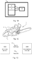
- FIG. 1A illustrates a schematic view of a two-stroke internal combustion engine 1.
- the engine 1 of FIG. 1 is crank case scavenged in which, for example, a mixture 40 of air 3 and fuel from a fuel supply system 20 (e.g., a carburetor or low pressure fuel injection system) is drawn to the engine crank house. From the crank house, the mixture 40 is carried through one or several scavenging passages 14 up to an engine combustion chamber 41.
- the engine combustion chamber 41 is provided with a spark plug 50 that ignites the compressed air-fuel mixture.
- Exhaust 42 may exit through an exhaust port 43 and through a silencer 13.
- the engine 1 may also include a piston 6 that is attached to a crank portion 12 equipped with a counter weight via a connecting rod 11.
- the piston 6 assumes an intermediate position in which flow is possible both through the intake port 44, the exhaust port 43 and through the scavenging passage 14.
- the mouth of intake passage 21 into the cylinder 5 may be referred to as the intake port 44.
- the intake passage 21 may be closed by the piston 6.
- By opening and closing the intake passage 21 varying flow speeds and pressures may be created inside the passage.
- the supplied amounts of fuel may be considered to be affected by the varying flow speeds and pressures inside the intake passage 21 based on opening and closing of the intake passage 21. Since the crank case in crank case scavenged two-stroke engines or crank case scavenged four-stroke engines can hold a considerable amount of fuel and consequently serve as a leveling reservoir, it is not necessary to adjust the fuel supply for each revolution. Instead, adjustment of fuel supply in one revolution may affect subsequent revolutions.
- FIG. 1B shows a schematic block diagram view of an engine 1, such as the engine of figure 1A .
- the engine 1 comprises a controller 100 for controlling the operation of the engine 1.
- the controller is connected to various components of the engine 1, such as the fuel supply system 20, and/or a spark ignition 50 and/or other various components.
- the controller 100 may comprise one or more electronic control units (ECU), possibly arranged to control one or several components each. In this manner, which is known to a person skilled in engines, the control of the engine 1 may be distributed locally. In the text below there will be made no differentiation whether the operation is controlled by a central processor or a distributed processor, possibly in co-operation with another distributed processor.
- ECU electronice control unit
- a method according to herein may be implemented and performed partially by a first electronic control unit, and also be implemented and performed partially by a second electronic control unit, wherein the first and second electronic control units complement each other and are both considered to be part of the same controller.
- the controller 100 may comprise one ECU for controlling the fuel supply system 20 and another ECU for controlling the spark ignition system 50, alternatively the controller 100 may comprise one ECU for controlling both the fuel supply system 20 and the spark ignition system 50.
- the controller may comprise one ECU for controlling both the fuel supply system 20 and the spark ignition system 50 wherein one ECU receives commands or data from the other ECU.
- controller 100 various ECUs will be commonly referred to as the controller 100. Also, other ECUs may be utilized for example for monitoring the engine revolution speed.
- the controller is thus arranged to monitor and/or control the engine revolution speed, the fuel supply system and the ignition module or system.
- the one or more controllers 100 will hereafter be referred to as one and the same controller 100 making no differentiation of which processor is executing which operation. It should be noted that the execution of a task may be divided between the controllers wherein the controllers will exchange data and/or commands to execute the task. For example, if one processor monitors the engine revolution speed, such as an ignition system electronic unit (referenced 100B in figure ID below), and forwards data on this to a processor regulating the fuel supply system, such as a fuel supply system electronic unit (referenced 100A in figure ID below), these processor actions will be referred to as having been made by the controller 100, the controller 100 thus comprising both the processor monitoring the engine revolution speed and the processor regulating the fuel supply system.
- the engine revolution speed such as an ignition system electronic unit (referenced 100B in figure ID below)
- a processor regulating the fuel supply system such as a fuel supply system electronic unit (referenced 100A in figure ID below)
- these processor actions will be referred to as having been made by the controller 100, the controller
- FIG. ID shows an example of how a fuel supply electronic control unit (ECU) 100A may be connected to an ignition system electronic control unit 100B.
- the fuel supply ECU 100A is connected to the ignition system ECU 100B through two wires, a ground wire 102 and a multi purpose communication wire 101.
- the multi purpose communication wire 101 may be used to relay the current revolution speed to the fuel supply system for regulating the fuel supply possibly including a revolution limiting function as disclosed herein based on the revolution speed.
- the multi purpose communication wire 101 may also or alternatively be used to relay the throttle angle to the fuel supply system for regulating the ignition possibly including a revolution limiting function as disclosed herein based on the throttle angle.
- FIG. 1C shows a hand-held power tool comprising an internal combustion engine as in figures 1A and 1B .
- the power-tool is exemplified as a chainsaw, but the teachings herein may also be used with other power tools, such as hedge cutters, pole saws, trimmers and brush cutters to name a few.
- the power tool 2 comprises an internal engine 1 (not visible as it is internal) and a handle 4, on which a throttle trigger 7 is arranged.
- the throttle trigger is effectively coupled to a throttle valve (referenced 23 in fig 2 ) of the fuel supply system in such a way that as the throttle trigger 7 is pushed or pulled, the throttle valve (referenced 23 in fig 2 ) changes its angle.
- FIG. 2 illustrates a carburetor type fuel supply system 20 in accordance with an example embodiment.
- the carburetor of the fuel supply system 20 includes the intake passage 21 having a venturi 22.
- a throttle valve 23 is rotatably supported or a throttle shaft 19 in the intake passage 21, along with a choke valve 24.
- the carburetor of the fuel supply system 20 also includes a fuel pump 25, which draws fuel from a fuel tank 26.
- the fuel pump 25 may be a pulsation controlled diaphragm pump, which could be driven by pressure pulses generated by a crank case of the engine 1 of FIG. 1 .
- the fuel pump 25 delivers fuel, via a needle valve 27, to a fuel metering chamber 28 of a fuel regulator 29.
- the fuel metering chamber 28 may be separated from atmospheric pressure by a diaphragm 30 and may be configured to hold a predetermined amount of fuel.
- a duct 31 from fuel metering chamber 28 may lead to a fuel valve 32.
- the fuel valve 32 may be a bistable valve, operating between open and closed positions.
- the fuel valve 32 may open or close the interconnection between the fuel metering chamber 28 and the fuel lines (33 and 34), leading to the intake passage 21.
- the fuel valve 32 may be a continuous or variable valve, operating between open and closed positions and also intermediate positions. The fuel valve is thus arranged to control the fuel supply.
- a finer channel 33 among the fuel lines may lead to an idle nozzle 35 downstream of the throttle valve 23.
- the fuel valve 32 which may in some cases be solenoid operated, may be controlled by the controller 100.
- the controller 100 may also control operation of the spark plug 50 for the application of spark to ignite the mixture 40 in the combustion chamber 41.
- the controller 100 may be an ignition control device.
- controller 100 may receive sensor inputs such as, for example, throttle position from a throttle position sensor 101 (or sensors), engine speed data from an engine speed sensor 102 (or sensors), and/or inputs from an additional sensor 103 (or sensors).
- the additional sensor 103 could be a temperature sensor or any other suitable parameter measurement sensor.
- the controller 100 may use the sensor inputs to control the A/F ratio by deciding when to open or close the fuel valve 32 and/or to control the timing of application of spark for ignition of the mixture 40 in the combustion chamber 41. In this capacity, the controller 100 may be used to limit engine speed at start-up to prevent inadvertent operation of the working assembly, as discussed in greater detail below. In an alternate embodiment, the controller 100 may function as a control module including engine management logic that communicates with an independent ignition module that controls the application of spark to the mixture 40 and ignition timing. The ignition module, whether a component of the controller 100 or independent of the ECU, has at least two modes of ignition, a start-up mode and normal mode, as discussed in great detail below.
- the throttle valve which is arranged to provide its current operating angle or position (i.e. how much it is opened) to the controller as will be disclosed below with reference to figure 3 , is primarily used to determine a proper fuel supply.
- the throttle position is also used to determine whether a conscious and willful increase of the revolution speed, such as through operation of the throttle, is being effected or not. This is used to enable the controller to maintain the revolution speed of the engine under or around a predetermined threshold value, to prevent the engine from racing unintentionally and thereby preventing the power tool from unintentionally start operating, which in the example of a chain saw means that the chain will be prevented from moving, at least at any speed at which the chain saw would be effective as a cutting tool.
- the throttle position is sensed by the throttle position sensor and provided to the controller (which may be comprised of several electronic control units as discussed above), and if it is sensed that the throttle is moved to a position outside either a first area (C+/C-) or a second area (B+/B-), the controller will determine that a willful activation of the throttle has taken place and will thereafter operate in the normal mode.
- the first area (C+/C-) may be determined upon startup as an area around the current throttle position. Moving the throttle position outside this area indicates that the throttle is being moved intentionally. In one embodiment the first area may be 5 percent of the full range of operation for the valve. In one embodiment the first area may be in the range 3 to 12 percent of the full range of operation for the valve.
- the first area may be in the range 3 to 30 percent of the full range of operation for the valve.
- the second area (B+/B-) may be set by designers and indicates a throttle position area inside which the start-up mode should be initiated. By starting the power tool engine in a throttle position outside this second area, a user may indicate that he is intending on using the power tool imminently and no startup mode is necessary. As such, the controller will not activate the start-up mode, but start directly in the normal mode.
- the throttle position sensor (being a known entity in combustion engines) is thus utilized for two purposes, both for determining a proper fuel supply, and for determining that a revolution speed increase is intentional on behalf of the user.
- the controller may also be configured to determine that the throttle position is outside either or both of the first and second areas, before deactivating the start-up mode and operating according to the normal mode. This ensures that the throttle activation was intentionally and protects against short unintentional activations of the throttle activating the tool.
- Engine speed data may be obtained via any of a number of different ways.
- a flywheel that rotates with the same speed as the engine crank may have one or more magnets provided on its periphery.
- the magnets can be used to provide energy to the ignition system as well as to other electronic components such as the controller 100, but may also be used for monitoring the engine speed by having the engine speed sensor 102 comprising a stationary detection unit arranged to detect each time the magnet (or magnets) of the flywheel pass the detection unit.
- the accuracy of the engine speed sensor 102 may be dependent upon the number of magnets on the flywheel and the number of detection units.
- the controller is thus configured to receive a sensor reading indicating the revolution speed.
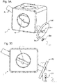
- Throttle position data is preferably obtained via the throttle position sensor 101 shown in FIG. 3 , which includes FIGS. 3A and 3B , showing perspective and side views, respectively.
- Magnetic sensing element 320 is an analogous hall device that is mounted in a fixed manner to a stationary portion of the fuel supply system 20.
- the analogous hall device 320 has a hall element 321 which is configured to generate an output voltage that is proportional to the magnetic flux density through the hall element 321.
- the analogous hall device 320 can have an integrated circuit for compensating for different conditions, such as temperature changes.
- a movable portion 340 has a substantially disc-like shape and is attached to the throttle shaft 19 at its center and has two magnets 310 being polarized in a direction preferably perpendicular to the fixed portion.
- the movable portion 340 can of course be configured differently, e.g. having a triangular shape, or being provided with only one magnet 310 or more than two magnets 310.
- the magnets 310 are secured to the movable portion 340 at a distance from the axis of rotation and the magnets 310 are separated by approximately 75°.
- the two magnets 310 are polarized in opposite direction in relation to each other, so as to form a magnetic flux density through the hall element 321 of the hall effect device 320 that is substantially proportional to the size of rotation of the movable portion 340 and the throttle shaft 19. Consequently, the analogous hall sensor 320 generates an output voltage being approximately linear in relation to size of rotation of the throttle shaft 19 and the throttle valve 23.
- the throttle position data may thus comprise either such an output voltage based on which the position of the throttle valve can be determined, an intermediate result based on which the position of the throttle valve can be determined or the determined position of the throttle valve.
- an engine speed limitation operation may be applied by altering the ignition timing of the engine.
- Altering the ignition timing may be utilized either alone or in combination with skipping ignition of the engine when the engine is initially started and when the engine revolution speed exceeds a threshold, dependent upon the position of the throttle valve 23 within its operating range at the start-up of the engine 1.
- limiting the engine's speed below the clutch-in speed of the clutch that drives a device's working assembly may be accomplished by limiting such as by skipping ignition or timing of ignition spark.
- the fuel supply may be controlled during start-up operations by closing the fuel valve 32 (e.g., shutting off the fuel supply) during a number (Ns) of evenly distributed revolutions.
- the fuel valve 32 may be closed during the entire intake cycle for the revolutions for which it is closed, and may be fully open during the entire intake cycle for revolutions for which it is open.
- limiting ignition and controlling fuel supply as a means of limiting the speed of an engine are provided in WO 2009/116902 , which is incorporated herein in its entirety and, as such, are not repeated here.
- Limitation of the engine's speed by way of the noted methods is preferably maintained until a deliberate act such as, but not limited to, manipulation of the throttle valve is taken by the operator of the device which indicates that he intends for the working assembly to be activated.
- curved line 400 represents the full operating range of the throttle valve 23, and arrow 402 represents the position of the throttle valve 23 within that range.
- the range indicated by B - /B + is the range of start-up throttle valve positions for which the controller 100 will initiate a speed limitation operation, thereby maintaining the speed of the engine 1 below the clutch-in speed at which the engine 1 engages the corresponding working assembly.
- the range B - /B + has been selected so that the controller 100 initiates a speed limitation operation for all possible start-up positions of the throttle valve 23.
- the range indicated by C - /C + represents the amount to which the throttle valve 23 must be moved in either the opening or closing directions before the controller 100 will cease the speed limitation operation on the engine so that normal operations may continue.
- the range C - /C + is selected to be large enough that only a deliberate repositioning of the throttle valve 23 by the operator will terminate the speed limitation operation, thereby preventing inadvertent engagement of the working assembly by the engine 1.
- Range C - /C + can be selected to be the same angle range regardless of the start-up position 402 of the throttle valve 23.
- the angle range C - /C + can depend upon the particular start-up position of the throttle valve 23 within range B - /B + .
- the angle range C - /C + may be set with respect to the extent or size as well or alternatively with respect to the position based on the particular start-up position.
- the range indicated by B - /B + is the range of start-up throttle valve positions for which the controller 100 will initiate a speed limitation operation, thereby maintaining the speed of the engine 1 below the clutch-in speed at which the engine 1 engages the corresponding working assembly.
- the range B - /B + has been selected to include only a small portion of the full operating range 400 of the throttle valve 23, leaving two portions of the operating range, indicated by A, outside of range B - /B + .
- the speed limit operation is deactivated directly from the start-up of the engine.
- the range indicated by C - /C + is again provided to indicate the amount to which the throttle valve 23 must be moved in either the opening or closing directions before the controller 100 will cease the speed limitation operation on the engine.
- the C - /C + range may be set to be static upon startup or dynamic and change as the throttle valve position falls within the B - /B + range.
- the present embodiment includes a range of start-up throttle valve positions, indicated by range B - /B + , for which the controller 100 initiates a speed limitation operation on the engine 1.
- range B - /B + extends all the way to the idle position of the throttle valve 23
- A only one range exists, indicated by A, for which the speed limitation operation by the controller 100 is deactivated directly from start-up.
- range C - /C + is provided so that the speed limitation operation is terminated after the throttle valve 23 is moved the predetermined distance. Note, where the start-up throttle valve position 402 falls within range A ( FIG. 7 ), range C - /C + is not necessary as the speed limit operation is deactivated at start-up.
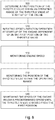
- FIG. 8 illustrates a block diagram of a method of controlling an internal combustion engine.
- the method may include determining a first position of the throttle valve within an operating range of the throttle valve at start-up of the engine 500, initiating a speed limitation operation at start-up of the engine dependent upon the first position of the throttle valve 510, monitoring engine speed 520, monitoring the position of the throttle valve within the operating range 530, and maintaining the speed of the engine below a predetermined speed until the throttle valve is moved from the first position 540.
- a power tool is started when the throttle valve is in an opened position which is such that not only does it provide for a fast idle, it will also provide for an engine revolution speed that will continue to grow, at least above a threshold.
- the functionality of the teachings herein will be activated and limit the engine revolution speed, by changing the timing of the ignition or skipping at least some ignition sparks completely. The engine will then reduce its revolution speed (significantly) and the engine revolution speed will fall below the threshold thus maintaining a safe operation.
- One benefit of controlling the ignition module is that it provides for a precise control that is easy to implement for a wide range of engines, that does not need to be calibrated and that does not risk causing an (unnecessary) increase in exhaust fumes.
- the number of sparks that should be skipped may be based on the amount that the revolution speed exceeds the threshold values.
- the controller will thus be configured to skip a number of sparks based on the difference between the current revolution speed and the threshold value, so that an increase in revolution speed leads to an increase in number of sparks skipped.
- the controller may be configured to control the ignition by changing the ignition timing. For example, to reduce the speed of the engine, the timing may be moved so that it happens earlier in a revolution cycle. The chamber will then not have received as much fuel, and the fuel has not yet been compressed. The result is that the engine provides less power on that ignition than it would if the timing had been correct.
- the controller is thus configured to limit the revolution speed by adapting the timing of the ignition.
Landscapes
- Engineering & Computer Science (AREA)
- Chemical & Material Sciences (AREA)
- Combustion & Propulsion (AREA)
- Mechanical Engineering (AREA)
- General Engineering & Computer Science (AREA)
- Theoretical Computer Science (AREA)
- Signal Processing (AREA)
- Control Of Throttle Valves Provided In The Intake System Or In The Exhaust System (AREA)
- Combined Controls Of Internal Combustion Engines (AREA)
- Ignition Installations For Internal Combustion Engines (AREA)
- Electrical Control Of Ignition Timing (AREA)
Claims (14)
- Moteur à combustion interne (1) agencé pour être utilisé avec un outil électrique (2) et pour entraîner un ensemble de travail dudit outil électrique (2), ledit ensemble de travail ayant un embrayage, ledit moteur (1) comprenant :une chambre de combustion (41) dans laquelle un mélange (40) de carburant et d'air est fourni ;une bougie d'allumage (50) disposée à proximité de la chambre de combustion pour allumer le mélange (40) en générant une étincelle, l'allumage du mélange entraînant un piston couplé de manière fonctionnelle à une partie de manivelle du moteur ;un système d'alimentation en carburant (20) comportant une soupape à carburant (32) et le papillon des gaz (23), la soupape à carburant (32) étant agencée pour commander la fourniture de carburant dans le mélange (40) et le papillon des gaz (23) pouvant être réglé pour commander la fourniture d'air dans le mélange ;un capteur de position de papillon (101) configuré pour déterminer une position du papillon des gaz (23) dans toute sa plage de fonctionnement ;un capteur de vitesse (102) configuré pour déterminer la vitesse de moteur ; etun dispositif de commande (100) configuré pour commander le fonctionnement de la soupape à carburant (32) et de la bougie d'allumage (50), caractérisé en ce que le dispositif de commande est configuré, au démarrage du moteurpour recevoir une indication de la vitesse de moteur à partir du capteur de vitesse (102) et pour déterminer si la vitesse de moteur dépasse une valeur seuil, et, le cas échéant, pour lancer une opération de limitation de vitesse maintenant la vitesse de moteur en dessous d'une vitesse prédéterminée, où ledit dispositif de commande (100) est en outre configuré pour détecter que le papillon des gaz (23) se déplace d'une première position (402) de plus d'un seuil de distance (C) et ensuite interrompre l'opération de limitation de vitesse.
- Moteur à combustion interne (1) de la revendication 1, dans lequel l'opération de limitation de vitesse est lancée pour toute première position (402) du papillon des gaz (23) dans toute la plage de fonctionnement du papillon des gaz (23).
- Moteur à combustion interne (1) de la revendication 1 ou 2, dans lequel l'opération de limitation de vitesse est lancée pour toute première position (402) du papillon des gaz (23) qui est dans une plage de fonctionnement du papillon des gaz (23) qui ne représente qu'une partie de toute la plage de fonctionnement du papillon des gaz (23).
- Moteur à combustion interne (1) de la revendication 1, 2 ou 3, dans lequel l'opération de limitation de vitesse est maintenue jusqu'à ce que le papillon des gaz (23) se déplace d'une partie prédéterminée de toute la plage de fonctionnement du papillon des gaz (23) de la première position (402).
- Moteur à combustion interne (1) de la revendication 4, dans lequel la partie prédéterminée représente trois à trente pour cent de toute la plage de fonctionnement du papillon des gaz.
- Moteur à combustion interne (1) de la revendication 4, dans lequel la partie prédéterminée représente trois à douze pour cent de toute la plage de fonctionnement du papillon des gaz.
- Moteur à combustion interne (1) de l'une des revendications précédentes, dans lequel l'opération de limitation de vitesse maintient la vitesse de moteur en dessous d'une vitesse prédéterminée jusqu'à ce que le papillon des gaz (23) se déplace d'une partie prédéterminée (C+/C-) de toute la plage de fonctionnement du papillon des gaz (23) de la première position (402), et la partie prédéterminée de toute la plage de fonctionnement dépend de la première position (402) du papillon des gaz (23) dans toute la plage de fonctionnement du papillon des gaz (23).
- Moteur à combustion interne (1) de l'une des revendications précédentes, dans lequel la vitesse prédéterminée de l'opération de limitation de vitesse est une vitesse d'enclenchement d'embrayage du moteur (1) à laquelle l'embrayage s'engage avec l'ensemble de travail.
- Moteur à combustion interne (1) de l'une des revendications précédentes, dans lequel l'opération de limitation de vitesse comporte le fait de sauter l'application d'étincelles.
- Moteur à combustion interne (1) de l'une des revendications précédentes, dans lequel le dispositif de commande (100) est configuré pour sauter un certain nombre d'étincelles sur la base de la différence entre la vitesse de rotation actuelle et la valeur seuil, de sorte qu'une augmentation de la vitesse de rotation entraîne une augmentation du nombre d'étincelles sautées.
- Moteur à combustion interne (1) de l'une des revendications précédentes, dans lequel le dispositif de commande (100) est configuré pour limiter la vitesse de rotation en adaptant le calage de l'allumage.
- Moteur à combustion interne (1) de l'une des revendications précédentes, dans lequel le moteur (1) est prévu dans une scie à chaîne, des découpeuses, une scie à long manche, une débroussailleuse, un taille-haie ou un taille-bordures.
- Outil électrique (2) comprenant :un ensemble de travail configuré pour effectuer une opération de coupe ;un embrayage pour entraîner l'ensemble de travail ; etun moteur à combustion interne (1) selon l'une des revendications précédentes.
- Procédé de commande d'un moteur à combustion interne (1) agencé pour être utilisé avec un outil électrique (2) et pour entraîner un ensemble de travail dudit outil électrique (2), ledit moteur comportant un papillon des gaz (23), le procédé comprenant le fait :de déterminer une première position (402) du papillon des gaz (23) dans une plage de fonctionnement du papillon des gaz (23) au démarrage du moteur (1) ;de lancer une opération de limitation de vitesse au démarrage du moteur (1) en fonction de la première position (402) du papillon des gaz (23) ;de surveiller la vitesse de moteur ;de recevoir une indication de la vitesse de moteur à partir du capteur de vitesse (102) et de déterminer si la vitesse de moteur dépasse une valeur seuil, et, le cas échéant, de lancer une opération de limitation de vitesse maintenant la vitesse de moteur en dessous d'une vitesse prédéterminée,de détecter que le papillon des gaz (23) se déplace d'une première position (402) de plus d'un seuil de distance (C) et ensuite d'interrompre l'opération de limitation de vitesse.
Applications Claiming Priority (2)
| Application Number | Priority Date | Filing Date | Title |
|---|---|---|---|
| US201462096014P | 2014-12-23 | 2014-12-23 | |
| PCT/SE2015/050736 WO2016105258A1 (fr) | 2014-12-23 | 2015-06-24 | Ensemble et procédé de démarrage fiable d'un moteur à combustion interne |
Publications (3)
| Publication Number | Publication Date |
|---|---|
| EP3237739A1 EP3237739A1 (fr) | 2017-11-01 |
| EP3237739A4 EP3237739A4 (fr) | 2019-04-03 |
| EP3237739B1 true EP3237739B1 (fr) | 2020-05-13 |
Family
ID=56151122
Family Applications (1)
| Application Number | Title | Priority Date | Filing Date |
|---|---|---|---|
| EP15873733.8A Active EP3237739B1 (fr) | 2014-12-23 | 2015-06-24 | Moteur à combustion interne et procédé pour le démarrer avec securité |
Country Status (5)
| Country | Link |
|---|---|
| US (1) | US10590869B2 (fr) |
| EP (1) | EP3237739B1 (fr) |
| JP (1) | JP6659701B2 (fr) |
| CN (1) | CN107110041B (fr) |
| WO (1) | WO2016105258A1 (fr) |
Families Citing this family (3)
| Publication number | Priority date | Publication date | Assignee | Title |
|---|---|---|---|---|
| EP3387249B1 (fr) | 2015-12-07 | 2020-05-13 | Husqvarna AB | Outil de puissance à main et système de commande associé à ce dernier, et utilisation et procédé de commande |
| JP6611343B2 (ja) * | 2016-04-12 | 2019-11-27 | 株式会社やまびこ | 携帯式のエンジン作業機 |
| US11225922B2 (en) | 2018-08-02 | 2022-01-18 | Husqvarna Ab | Two-stroke engine control |
Family Cites Families (44)
| Publication number | Priority date | Publication date | Assignee | Title |
|---|---|---|---|---|
| US3498280A (en) * | 1968-07-15 | 1970-03-03 | Mcculloch Corp | Chain saw with carburetor heater |
| SE436913B (sv) | 1982-03-22 | 1985-01-28 | Electrolux Ab | Anordning vid forbrenningsmotorer med ett permanentmagnetpaverkat gnisttendsystem |
| SE8302113L (sv) | 1983-04-15 | 1984-10-16 | Electrolux Ab | Tendsystem med tillsatsfunktioner |
| JPS6110972U (ja) | 1984-06-27 | 1986-01-22 | 株式会社 共立 | 内燃機関駆動装置 |
| JPH041342Y2 (fr) | 1984-09-05 | 1992-01-17 | ||
| SE450029B (sv) | 1985-02-27 | 1987-06-01 | Electrolux Ab | Momentbegrensande anordning i forbrenningsmotor med magnettendsystem |
| JP2520161Y2 (ja) | 1988-06-20 | 1996-12-11 | 本田技研工業株式会社 | 草刈作業機の制御装置 |
| DE3923237C2 (de) | 1988-08-03 | 1994-01-27 | Stihl Maschf Andreas | Zündschaltung für einen Verbrennungsmotor |
| DE3914026C1 (fr) | 1989-04-28 | 1990-09-06 | Pruefrex-Elektro-Apparatebau Inh. Helga Mueller, Geb. Dutschke, 8501 Cadolzburg, De | |
| DE4326010A1 (de) | 1993-08-03 | 1995-02-09 | Stihl Maschf Andreas | Zündschaltung für einen Verbrennungsmotor |
| US5551395A (en) | 1994-07-12 | 1996-09-03 | Homelite, Inc. | Control system for power tool with internal combustion engine |
| DE19501299B4 (de) * | 1995-01-18 | 2006-04-13 | Robert Bosch Gmbh | Verfahren und Vorrichtung zur Steuerung einer Brennkraftmaschine eines Fahrzeugs |
| DE19728349A1 (de) * | 1997-07-03 | 1999-01-07 | Telefunken Microelectron | Sensoranordnung und Motorsteuerungseinrichtung für einen Verbrennungsmotor |
| JP3945612B2 (ja) | 2000-06-02 | 2007-07-18 | 三菱電機株式会社 | 自動変速機付きエンジンの制御装置 |
| JP4060517B2 (ja) | 2000-07-18 | 2008-03-12 | 本田技研工業株式会社 | エンジンの回転数制御装置 |
| US6408820B1 (en) | 2000-08-02 | 2002-06-25 | Walbro Corporation | Capacitor discharge engine ignition system with automatic ignition advance and/or minimum ignition speed control |
| WO2005026515A2 (fr) * | 2003-09-10 | 2005-03-24 | Pcrc Products | Dispositif et procede permettant de commander les operations d'un moteur a combustion interne equipe d'un systeme d'injection electronique |
| US7381009B2 (en) | 2003-11-07 | 2008-06-03 | Wacker Corporation | Starter module for walk behind trowel |
| DE102004051259B4 (de) | 2004-10-21 | 2020-10-22 | Andreas Stihl Ag & Co. Kg | Drehzahlschutzschaltung für eine Fliehkraftkupplung |
| JP4528174B2 (ja) | 2005-03-18 | 2010-08-18 | 本田技研工業株式会社 | 歩行型作業機 |
| CN100557229C (zh) | 2005-07-01 | 2009-11-04 | 胡斯华纳有限公司 | 启动安全点火系统 |
| EP1995027B1 (fr) | 2007-05-21 | 2010-09-08 | Emak S.p.A. | Système de sécurité pour empêcher l'entraînement de l'outil dans des scies électriques lorsque le moteur tourne |
| US8257227B2 (en) | 2007-07-31 | 2012-09-04 | Vermeer Manufacturing Company | Method and apparatus for decelerating a material reduction tool |
| WO2009085006A1 (fr) | 2008-01-01 | 2009-07-09 | Husqvarna Ab | Commande de limitation de régime de moteur |
| US8220165B2 (en) | 2008-01-31 | 2012-07-17 | Robert Bosch Gmbh | Support foot locking arrangement for a reciprocating tool |
| CN101978152B (zh) * | 2008-03-17 | 2013-07-03 | 胡斯华纳有限公司 | 燃料供应单元 |
| US7735471B2 (en) | 2008-07-16 | 2010-06-15 | Walbro Engine Management, L.L.C. | Controlling a light-duty combustion engine |
| DE102009061741B3 (de) * | 2008-11-20 | 2021-05-06 | Yamabiko Corporation | Arbeitsgerät mit Verbrennungsmotor |
| DE102009036372A1 (de) | 2009-08-06 | 2011-02-10 | Andreas Stihl Ag & Co. Kg | Tragbares Arbeitsgerät |
| CN101761437B (zh) | 2009-10-27 | 2011-06-29 | 力帆实业(集团)股份有限公司 | 摩托车点火控制系统 |
| DE102011010069A1 (de) * | 2011-02-01 | 2012-08-02 | Andreas Stihl Ag & Co. Kg | Verfahren zur Steuerung der Drehzahlbegrenzung eines Verbrennungsmotors |
| DE102011103125B4 (de) | 2011-05-25 | 2022-03-03 | Andreas Stihl Ag & Co. Kg | Verfahren zum Betrieb eines Arbeitsgeräts |
| JP5818226B2 (ja) | 2011-08-19 | 2015-11-18 | 日立工機株式会社 | エンジン及びエンジン作業機 |
| US9651138B2 (en) | 2011-09-30 | 2017-05-16 | Mtd Products Inc. | Speed control assembly for a self-propelled walk-behind lawn mower |
| DE102011120812B4 (de) | 2011-12-10 | 2022-06-02 | Andreas Stihl Ag & Co. Kg | Verfahren zum Betrieb eines handgeführten Arbeitsgeräts |
| DE102012002225A1 (de) | 2012-02-04 | 2013-08-08 | Andreas Stihl Ag & Co. Kg | "Handgeführtes Arbeitsgerät" |
| DE102012012801A1 (de) | 2012-06-28 | 2014-01-02 | Andreas Stihl Ag & Co. Kg | Arbeitsgerät |
| WO2014002951A1 (fr) | 2012-06-29 | 2014-01-03 | 株式会社マキタ | Dispositif de puissance et machine de travail portative équipée associée |
| DE102012015034A1 (de) | 2012-07-31 | 2014-02-27 | Andreas Stihl Ag & Co. Kg | Verfahren zur Abschaltung einer Drehzahlbegrenzung bei einem Verbrennungsmotor |
| WO2014038987A1 (fr) | 2012-09-04 | 2014-03-13 | Husqvarna Ab | Outils électriques équipés d'au moins une lame à mouvement réciproque |
| US20140166323A1 (en) | 2012-09-16 | 2014-06-19 | J. Carl Cooper | Kickback Reduction for Power Tools and Machines |
| DE102012024840A1 (de) * | 2012-12-19 | 2014-06-26 | Andreas Stihl Ag & Co. Kg | Verfahren zum Betrieb eines Verbrennungsmotors in einem handgeführten Arbeitsgerät |
| DE102012112948A1 (de) | 2012-12-21 | 2014-06-26 | Makita Corp. | Verfahren und Vorrichtung zur Steuerung des Betriebs einer Verbrennungskraftmaschine |
| JP6105361B2 (ja) | 2013-04-09 | 2017-03-29 | 本田技研工業株式会社 | 汎用内燃機関の制御装置 |
-
2015
- 2015-06-24 US US15/538,058 patent/US10590869B2/en active Active
- 2015-06-24 JP JP2017533517A patent/JP6659701B2/ja active Active
- 2015-06-24 EP EP15873733.8A patent/EP3237739B1/fr active Active
- 2015-06-24 CN CN201580070522.1A patent/CN107110041B/zh active Active
- 2015-06-24 WO PCT/SE2015/050736 patent/WO2016105258A1/fr active Application Filing
Non-Patent Citations (1)
| Title |
|---|
| None * |
Also Published As
| Publication number | Publication date |
|---|---|
| EP3237739A1 (fr) | 2017-11-01 |
| JP6659701B2 (ja) | 2020-03-04 |
| US20180010531A1 (en) | 2018-01-11 |
| US10590869B2 (en) | 2020-03-17 |
| WO2016105258A1 (fr) | 2016-06-30 |
| JP2017538894A (ja) | 2017-12-28 |
| EP3237739A4 (fr) | 2019-04-03 |
| CN107110041A (zh) | 2017-08-29 |
| CN107110041B (zh) | 2020-10-16 |
Similar Documents
| Publication | Publication Date | Title |
|---|---|---|
| CN100510353C (zh) | 离心离合器的转速保护转换装置 | |
| US9140204B2 (en) | Handheld work apparatus having an air-cooled combustion engine | |
| RU2640145C2 (ru) | Способ управления числом оборотов двигателя внутреннего сгорания (варианты) | |
| US9873193B2 (en) | Method for operating a handheld work apparatus having a combustion engine | |
| US20140230787A1 (en) | Engine and engine-operated working machine | |
| AU2007281136A1 (en) | Small engine operation components | |
| EP3237739B1 (fr) | Moteur à combustion interne et procédé pour le démarrer avec securité | |
| JP6313966B2 (ja) | 手で操縦される作業機における内燃エンジンの作動方法 | |
| US9670837B2 (en) | Engine-powered work tool provided with wind governor that performs ignition control | |
| JP5861913B2 (ja) | 手持ち式エンジン作業機の燃料調整方法 | |
| EP3386668B1 (fr) | Outil lectroportatif, système de contrôle associé et son utilisation, et méthode de contrôle d'un tel outil | |
| US8770172B2 (en) | Fuel shortage detecting apparatus for general-purpose engine | |
| US20190024611A1 (en) | Internal combustion engine provided with a semi- automatic choke device | |
| WO2014002951A1 (fr) | Dispositif de puissance et machine de travail portative équipée associée | |
| US9938955B2 (en) | Adjustment of ignition timing at cut out | |
| JP2012149644A (ja) | 内燃エンジン、内燃エンジン用診断装置、および内燃エンジンの調整方法 | |
| JP7108472B2 (ja) | エンジン駆動式刈払機 | |
| JP2012154183A (ja) | 補器の発電器を備えたエンジンの回転数検知装置 | |
| US10247165B2 (en) | Handheld engine-driven working machine | |
| JP5357120B2 (ja) | 汎用エンジンの燃料切れ判定装置 | |
| CN110741147A (zh) | 化油器组件启动设置检测装置 |
Legal Events
| Date | Code | Title | Description |
|---|---|---|---|
| STAA | Information on the status of an ep patent application or granted ep patent |
Free format text: STATUS: THE INTERNATIONAL PUBLICATION HAS BEEN MADE |
|
| PUAI | Public reference made under article 153(3) epc to a published international application that has entered the european phase |
Free format text: ORIGINAL CODE: 0009012 |
|
| STAA | Information on the status of an ep patent application or granted ep patent |
Free format text: STATUS: REQUEST FOR EXAMINATION WAS MADE |
|
| 17P | Request for examination filed |
Effective date: 20170609 |
|
| AK | Designated contracting states |
Kind code of ref document: A1 Designated state(s): AL AT BE BG CH CY CZ DE DK EE ES FI FR GB GR HR HU IE IS IT LI LT LU LV MC MK MT NL NO PL PT RO RS SE SI SK SM TR |
|
| AX | Request for extension of the european patent |
Extension state: BA ME |
|
| DAV | Request for validation of the european patent (deleted) | ||
| DAX | Request for extension of the european patent (deleted) | ||
| A4 | Supplementary search report drawn up and despatched |
Effective date: 20190304 |
|
| RIC1 | Information provided on ipc code assigned before grant |
Ipc: F02D 41/06 20060101AFI20190226BHEP Ipc: F02D 43/04 20060101ALI20190226BHEP Ipc: F02P 5/145 20060101ALI20190226BHEP Ipc: F02D 41/32 20060101ALI20190226BHEP |
|
| STAA | Information on the status of an ep patent application or granted ep patent |
Free format text: STATUS: EXAMINATION IS IN PROGRESS |
|
| 17Q | First examination report despatched |
Effective date: 20191018 |
|
| GRAP | Despatch of communication of intention to grant a patent |
Free format text: ORIGINAL CODE: EPIDOSNIGR1 |
|
| STAA | Information on the status of an ep patent application or granted ep patent |
Free format text: STATUS: GRANT OF PATENT IS INTENDED |
|
| INTG | Intention to grant announced |
Effective date: 20191217 |
|
| GRAS | Grant fee paid |
Free format text: ORIGINAL CODE: EPIDOSNIGR3 |
|
| GRAA | (expected) grant |
Free format text: ORIGINAL CODE: 0009210 |
|
| STAA | Information on the status of an ep patent application or granted ep patent |
Free format text: STATUS: THE PATENT HAS BEEN GRANTED |
|
| AK | Designated contracting states |
Kind code of ref document: B1 Designated state(s): AL AT BE BG CH CY CZ DE DK EE ES FI FR GB GR HR HU IE IS IT LI LT LU LV MC MK MT NL NO PL PT RO RS SE SI SK SM TR |
|
| REG | Reference to a national code |
Ref country code: GB Ref legal event code: FG4D |
|
| REG | Reference to a national code |
Ref country code: CH Ref legal event code: EP |
|
| REG | Reference to a national code |
Ref country code: DE Ref legal event code: R096 Ref document number: 602015052899 Country of ref document: DE |
|
| REG | Reference to a national code |
Ref country code: AT Ref legal event code: REF Ref document number: 1270596 Country of ref document: AT Kind code of ref document: T Effective date: 20200615 |
|
| REG | Reference to a national code |
Ref country code: LT Ref legal event code: MG4D |
|
| REG | Reference to a national code |
Ref country code: NL Ref legal event code: MP Effective date: 20200513 |
|
| PG25 | Lapsed in a contracting state [announced via postgrant information from national office to epo] |
Ref country code: GR Free format text: LAPSE BECAUSE OF FAILURE TO SUBMIT A TRANSLATION OF THE DESCRIPTION OR TO PAY THE FEE WITHIN THE PRESCRIBED TIME-LIMIT Effective date: 20200814 Ref country code: NO Free format text: LAPSE BECAUSE OF FAILURE TO SUBMIT A TRANSLATION OF THE DESCRIPTION OR TO PAY THE FEE WITHIN THE PRESCRIBED TIME-LIMIT Effective date: 20200813 Ref country code: FI Free format text: LAPSE BECAUSE OF FAILURE TO SUBMIT A TRANSLATION OF THE DESCRIPTION OR TO PAY THE FEE WITHIN THE PRESCRIBED TIME-LIMIT Effective date: 20200513 Ref country code: LT Free format text: LAPSE BECAUSE OF FAILURE TO SUBMIT A TRANSLATION OF THE DESCRIPTION OR TO PAY THE FEE WITHIN THE PRESCRIBED TIME-LIMIT Effective date: 20200513 Ref country code: IS Free format text: LAPSE BECAUSE OF FAILURE TO SUBMIT A TRANSLATION OF THE DESCRIPTION OR TO PAY THE FEE WITHIN THE PRESCRIBED TIME-LIMIT Effective date: 20200913 Ref country code: PT Free format text: LAPSE BECAUSE OF FAILURE TO SUBMIT A TRANSLATION OF THE DESCRIPTION OR TO PAY THE FEE WITHIN THE PRESCRIBED TIME-LIMIT Effective date: 20200914 Ref country code: SE Free format text: LAPSE BECAUSE OF FAILURE TO SUBMIT A TRANSLATION OF THE DESCRIPTION OR TO PAY THE FEE WITHIN THE PRESCRIBED TIME-LIMIT Effective date: 20200513 |
|
| PG25 | Lapsed in a contracting state [announced via postgrant information from national office to epo] |
Ref country code: RS Free format text: LAPSE BECAUSE OF FAILURE TO SUBMIT A TRANSLATION OF THE DESCRIPTION OR TO PAY THE FEE WITHIN THE PRESCRIBED TIME-LIMIT Effective date: 20200513 Ref country code: HR Free format text: LAPSE BECAUSE OF FAILURE TO SUBMIT A TRANSLATION OF THE DESCRIPTION OR TO PAY THE FEE WITHIN THE PRESCRIBED TIME-LIMIT Effective date: 20200513 Ref country code: LV Free format text: LAPSE BECAUSE OF FAILURE TO SUBMIT A TRANSLATION OF THE DESCRIPTION OR TO PAY THE FEE WITHIN THE PRESCRIBED TIME-LIMIT Effective date: 20200513 Ref country code: BG Free format text: LAPSE BECAUSE OF FAILURE TO SUBMIT A TRANSLATION OF THE DESCRIPTION OR TO PAY THE FEE WITHIN THE PRESCRIBED TIME-LIMIT Effective date: 20200813 |
|
| REG | Reference to a national code |
Ref country code: AT Ref legal event code: MK05 Ref document number: 1270596 Country of ref document: AT Kind code of ref document: T Effective date: 20200513 |
|
| PG25 | Lapsed in a contracting state [announced via postgrant information from national office to epo] |
Ref country code: AL Free format text: LAPSE BECAUSE OF FAILURE TO SUBMIT A TRANSLATION OF THE DESCRIPTION OR TO PAY THE FEE WITHIN THE PRESCRIBED TIME-LIMIT Effective date: 20200513 Ref country code: NL Free format text: LAPSE BECAUSE OF FAILURE TO SUBMIT A TRANSLATION OF THE DESCRIPTION OR TO PAY THE FEE WITHIN THE PRESCRIBED TIME-LIMIT Effective date: 20200513 |
|
| PG25 | Lapsed in a contracting state [announced via postgrant information from national office to epo] |
Ref country code: ES Free format text: LAPSE BECAUSE OF FAILURE TO SUBMIT A TRANSLATION OF THE DESCRIPTION OR TO PAY THE FEE WITHIN THE PRESCRIBED TIME-LIMIT Effective date: 20200513 Ref country code: AT Free format text: LAPSE BECAUSE OF FAILURE TO SUBMIT A TRANSLATION OF THE DESCRIPTION OR TO PAY THE FEE WITHIN THE PRESCRIBED TIME-LIMIT Effective date: 20200513 Ref country code: CZ Free format text: LAPSE BECAUSE OF FAILURE TO SUBMIT A TRANSLATION OF THE DESCRIPTION OR TO PAY THE FEE WITHIN THE PRESCRIBED TIME-LIMIT Effective date: 20200513 Ref country code: RO Free format text: LAPSE BECAUSE OF FAILURE TO SUBMIT A TRANSLATION OF THE DESCRIPTION OR TO PAY THE FEE WITHIN THE PRESCRIBED TIME-LIMIT Effective date: 20200513 Ref country code: EE Free format text: LAPSE BECAUSE OF FAILURE TO SUBMIT A TRANSLATION OF THE DESCRIPTION OR TO PAY THE FEE WITHIN THE PRESCRIBED TIME-LIMIT Effective date: 20200513 Ref country code: IT Free format text: LAPSE BECAUSE OF FAILURE TO SUBMIT A TRANSLATION OF THE DESCRIPTION OR TO PAY THE FEE WITHIN THE PRESCRIBED TIME-LIMIT Effective date: 20200513 Ref country code: SM Free format text: LAPSE BECAUSE OF FAILURE TO SUBMIT A TRANSLATION OF THE DESCRIPTION OR TO PAY THE FEE WITHIN THE PRESCRIBED TIME-LIMIT Effective date: 20200513 Ref country code: DK Free format text: LAPSE BECAUSE OF FAILURE TO SUBMIT A TRANSLATION OF THE DESCRIPTION OR TO PAY THE FEE WITHIN THE PRESCRIBED TIME-LIMIT Effective date: 20200513 |
|
| REG | Reference to a national code |
Ref country code: CH Ref legal event code: PL |
|
| REG | Reference to a national code |
Ref country code: DE Ref legal event code: R097 Ref document number: 602015052899 Country of ref document: DE |
|
| PG25 | Lapsed in a contracting state [announced via postgrant information from national office to epo] |
Ref country code: MC Free format text: LAPSE BECAUSE OF FAILURE TO SUBMIT A TRANSLATION OF THE DESCRIPTION OR TO PAY THE FEE WITHIN THE PRESCRIBED TIME-LIMIT Effective date: 20200513 Ref country code: PL Free format text: LAPSE BECAUSE OF FAILURE TO SUBMIT A TRANSLATION OF THE DESCRIPTION OR TO PAY THE FEE WITHIN THE PRESCRIBED TIME-LIMIT Effective date: 20200513 Ref country code: SK Free format text: LAPSE BECAUSE OF FAILURE TO SUBMIT A TRANSLATION OF THE DESCRIPTION OR TO PAY THE FEE WITHIN THE PRESCRIBED TIME-LIMIT Effective date: 20200513 |
|
| PLBE | No opposition filed within time limit |
Free format text: ORIGINAL CODE: 0009261 |
|
| STAA | Information on the status of an ep patent application or granted ep patent |
Free format text: STATUS: NO OPPOSITION FILED WITHIN TIME LIMIT |
|
| PG25 | Lapsed in a contracting state [announced via postgrant information from national office to epo] |
Ref country code: LU Free format text: LAPSE BECAUSE OF NON-PAYMENT OF DUE FEES Effective date: 20200624 |
|
| REG | Reference to a national code |
Ref country code: BE Ref legal event code: MM Effective date: 20200630 |
|
| 26N | No opposition filed |
Effective date: 20210216 |
|
| GBPC | Gb: european patent ceased through non-payment of renewal fee |
Effective date: 20200813 |
|
| PG25 | Lapsed in a contracting state [announced via postgrant information from national office to epo] |
Ref country code: IE Free format text: LAPSE BECAUSE OF NON-PAYMENT OF DUE FEES Effective date: 20200624 Ref country code: CH Free format text: LAPSE BECAUSE OF NON-PAYMENT OF DUE FEES Effective date: 20200630 Ref country code: LI Free format text: LAPSE BECAUSE OF NON-PAYMENT OF DUE FEES Effective date: 20200630 |
|
| PG25 | Lapsed in a contracting state [announced via postgrant information from national office to epo] |
Ref country code: SI Free format text: LAPSE BECAUSE OF FAILURE TO SUBMIT A TRANSLATION OF THE DESCRIPTION OR TO PAY THE FEE WITHIN THE PRESCRIBED TIME-LIMIT Effective date: 20200513 Ref country code: BE Free format text: LAPSE BECAUSE OF NON-PAYMENT OF DUE FEES Effective date: 20200630 |
|
| PG25 | Lapsed in a contracting state [announced via postgrant information from national office to epo] |
Ref country code: GB Free format text: LAPSE BECAUSE OF NON-PAYMENT OF DUE FEES Effective date: 20200813 |
|
| PG25 | Lapsed in a contracting state [announced via postgrant information from national office to epo] |
Ref country code: TR Free format text: LAPSE BECAUSE OF FAILURE TO SUBMIT A TRANSLATION OF THE DESCRIPTION OR TO PAY THE FEE WITHIN THE PRESCRIBED TIME-LIMIT Effective date: 20200513 Ref country code: MT Free format text: LAPSE BECAUSE OF FAILURE TO SUBMIT A TRANSLATION OF THE DESCRIPTION OR TO PAY THE FEE WITHIN THE PRESCRIBED TIME-LIMIT Effective date: 20200513 Ref country code: CY Free format text: LAPSE BECAUSE OF FAILURE TO SUBMIT A TRANSLATION OF THE DESCRIPTION OR TO PAY THE FEE WITHIN THE PRESCRIBED TIME-LIMIT Effective date: 20200513 |
|
| PG25 | Lapsed in a contracting state [announced via postgrant information from national office to epo] |
Ref country code: MK Free format text: LAPSE BECAUSE OF FAILURE TO SUBMIT A TRANSLATION OF THE DESCRIPTION OR TO PAY THE FEE WITHIN THE PRESCRIBED TIME-LIMIT Effective date: 20200513 |
|
| PGFP | Annual fee paid to national office [announced via postgrant information from national office to epo] |
Ref country code: FR Payment date: 20220519 Year of fee payment: 8 |
|
| P01 | Opt-out of the competence of the unified patent court (upc) registered |
Effective date: 20230419 |
|
| PGFP | Annual fee paid to national office [announced via postgrant information from national office to epo] |
Ref country code: DE Payment date: 20230508 Year of fee payment: 9 |
|
| PG25 | Lapsed in a contracting state [announced via postgrant information from national office to epo] |
Ref country code: FR Free format text: LAPSE BECAUSE OF NON-PAYMENT OF DUE FEES Effective date: 20230630 |