EP3222575A1 - Systeme et procédé pour pour l'aération et l'évacuation des fumées dans une cage d'ascenseur - Google Patents
Systeme et procédé pour pour l'aération et l'évacuation des fumées dans une cage d'ascenseur Download PDFInfo
- Publication number
- EP3222575A1 EP3222575A1 EP17158925.2A EP17158925A EP3222575A1 EP 3222575 A1 EP3222575 A1 EP 3222575A1 EP 17158925 A EP17158925 A EP 17158925A EP 3222575 A1 EP3222575 A1 EP 3222575A1
- Authority
- EP
- European Patent Office
- Prior art keywords
- elevator shaft
- air
- elevator
- shaft
- fans
- Prior art date
- Legal status (The legal status is an assumption and is not a legal conclusion. Google has not performed a legal analysis and makes no representation as to the accuracy of the status listed.)
- Granted
Links
- 238000009423 ventilation Methods 0.000 title claims abstract description 52
- 238000010926 purge Methods 0.000 title 1
- 239000000779 smoke Substances 0.000 claims abstract description 83
- 238000000605 extraction Methods 0.000 claims abstract description 55
- 238000000034 method Methods 0.000 claims abstract description 11
- 230000002441 reversible effect Effects 0.000 claims description 5
- 241000446313 Lamella Species 0.000 claims description 3
- 239000003570 air Substances 0.000 description 138
- UGFAIRIUMAVXCW-UHFFFAOYSA-N Carbon monoxide Chemical compound [O+]#[C-] UGFAIRIUMAVXCW-UHFFFAOYSA-N 0.000 description 6
- 229910002091 carbon monoxide Inorganic materials 0.000 description 6
- 238000011161 development Methods 0.000 description 4
- 230000018109 developmental process Effects 0.000 description 4
- CURLTUGMZLYLDI-UHFFFAOYSA-N Carbon dioxide Chemical compound O=C=O CURLTUGMZLYLDI-UHFFFAOYSA-N 0.000 description 2
- 238000013461 design Methods 0.000 description 2
- 238000001514 detection method Methods 0.000 description 2
- 238000005399 mechanical ventilation Methods 0.000 description 2
- 239000012855 volatile organic compound Substances 0.000 description 2
- 230000003213 activating effect Effects 0.000 description 1
- 238000005273 aeration Methods 0.000 description 1
- 239000012080 ambient air Substances 0.000 description 1
- 229910002092 carbon dioxide Inorganic materials 0.000 description 1
- 239000001569 carbon dioxide Substances 0.000 description 1
- 238000010276 construction Methods 0.000 description 1
- 238000001816 cooling Methods 0.000 description 1
- 238000009795 derivation Methods 0.000 description 1
- 238000010790 dilution Methods 0.000 description 1
- 239000012895 dilution Substances 0.000 description 1
- 230000000694 effects Effects 0.000 description 1
- 239000007789 gas Substances 0.000 description 1
- 238000010438 heat treatment Methods 0.000 description 1
- 238000009434 installation Methods 0.000 description 1
- 238000012423 maintenance Methods 0.000 description 1
- 238000012544 monitoring process Methods 0.000 description 1
- 230000002035 prolonged effect Effects 0.000 description 1
- 229910052704 radon Inorganic materials 0.000 description 1
- SYUHGPGVQRZVTB-UHFFFAOYSA-N radon atom Chemical compound [Rn] SYUHGPGVQRZVTB-UHFFFAOYSA-N 0.000 description 1
- 230000000630 rising effect Effects 0.000 description 1
- 239000000243 solution Substances 0.000 description 1
- 238000010025 steaming Methods 0.000 description 1
- 238000012360 testing method Methods 0.000 description 1
- 238000013022 venting Methods 0.000 description 1
- 230000036642 wellbeing Effects 0.000 description 1
Images


Classifications
-
- F—MECHANICAL ENGINEERING; LIGHTING; HEATING; WEAPONS; BLASTING
- F24—HEATING; RANGES; VENTILATING
- F24F—AIR-CONDITIONING; AIR-HUMIDIFICATION; VENTILATION; USE OF AIR CURRENTS FOR SCREENING
- F24F11/00—Control or safety arrangements
- F24F11/0001—Control or safety arrangements for ventilation
-
- B—PERFORMING OPERATIONS; TRANSPORTING
- B66—HOISTING; LIFTING; HAULING
- B66B—ELEVATORS; ESCALATORS OR MOVING WALKWAYS
- B66B11/00—Main component parts of lifts in, or associated with, buildings or other structures
- B66B11/0005—Constructional features of hoistways
-
- F—MECHANICAL ENGINEERING; LIGHTING; HEATING; WEAPONS; BLASTING
- F24—HEATING; RANGES; VENTILATING
- F24F—AIR-CONDITIONING; AIR-HUMIDIFICATION; VENTILATION; USE OF AIR CURRENTS FOR SCREENING
- F24F7/00—Ventilation
- F24F7/04—Ventilation with ducting systems, e.g. by double walls; with natural circulation
- F24F7/06—Ventilation with ducting systems, e.g. by double walls; with natural circulation with forced air circulation, e.g. by fan positioning of a ventilator in or against a conduit
-
- F—MECHANICAL ENGINEERING; LIGHTING; HEATING; WEAPONS; BLASTING
- F24—HEATING; RANGES; VENTILATING
- F24F—AIR-CONDITIONING; AIR-HUMIDIFICATION; VENTILATION; USE OF AIR CURRENTS FOR SCREENING
- F24F11/00—Control or safety arrangements
- F24F11/30—Control or safety arrangements for purposes related to the operation of the system, e.g. for safety or monitoring
- F24F11/32—Responding to malfunctions or emergencies
- F24F11/33—Responding to malfunctions or emergencies to fire, excessive heat or smoke
Definitions
- the present invention relates to a system and also to a method for ventilating and / or de-smoking a lift shaft, in particular with elevator shafts, which are located in different elevator levels and are separate fire compartments of a building, which is bounded by vertical shaft walls.
- This opening is generally located in the elevator shaft head or, if present, in an elevator machinery room above it and leads directly outside the building envelope.
- Such solutions are disclosed, for example, in US Pat EP 1 890 956 B1 (with purely passive operated, natural ventilation system) or in the DE 20 2006 012 724 U1 (there with a fan used for the removal of smoke outside the building in an otherwise purely passive operated exhaust vent).
- Lift shaft ventilation and smoke extraction systems which control the natural ventilation and smoke extraction of the elevator shaft via a window or a flap in the shaft head or in the engine room, are known from the prior art. Although such a system could be used in the elevator shaft of the property described, it can not contribute to the safe operation of the elevator system due to the described lack of thermal in the elevator shaft, or not ensure the safety of the elevator users.
- the fans arranged on opposite sides in the elevator shaft can be arranged in particular in the elevator shaft in the area of the shaft walls on opposite sides. But they can also be arranged on opposite positions on two cabin walls of the elevator car.
- a hybrid form is also conceivable in which fans are arranged both on the cabin walls and in the area of the shaft walls, in which case one side of the elevator shaft has a zone of the shaft walls as well as a region of the cabin walls located there combined number of fans is arranged, on the opposite side of a fan group is formed by arranged there in the region of the shaft walls and the cabin walls fan.
- the control is set up to control the fans in such a way when a need for ventilation of the elevator car and / or the elevator shaft is known that fans arranged on a first of the two sides convey air in the elevator shaft in an upward conveying direction (this can then be done, for example, by the above-mentioned first fan group), on a second of the two sides in the elevator shaft arranged fan (eg also by the example second fan group) promote air in the elevator shaft in a downward conveying direction, and the controller continues to do so is arranged, upon detecting a need for a smoke removal of the hoistway to control the drive motor for the second closure element in such a way that it opens the exhaust and smoke extraction duct, and to control the fans in a manner to operate that all airs arranged in the elevator shaft Air in the elevator shaft in an equally directed conveying direction in the direction of a vertical or horizontal position in which the exhaust air and smoke extraction channel opens into the elevator shaft, promote.
- the fresh air volume in the elevator shaft is sufficient in order to supply the elevator car with fresh air for a sufficiently long service life from this reservoir.
- the supply air duct open by moving the closure element associated therewith and can flow fresh air.
- the exhaust air and smoke extraction duct is opened to dissipate excess air over it.
- the fans can be operated in opposite directions in particular in the manner described above, in order to maintain the air circulation in this case upright and to distribute distributed fresh air accordingly, to push air to be discharged from the exhaust air and smoke extraction duct.
- the fans are all operated in a conveying direction, ie run the fans of either side compared to the case of pure ventilation in the opposite direction to so to push the air with the smoke in one direction and in the direction of the then opened exhaust and smoke extraction duct to derive the smoke there from the elevator shaft.
- the supply air duct can be opened in order to track over this fresh and smoke-free air into the elevator shaft, there to provide fresh air, at least for a dilution of the smoke.
- opposite sides on which the fans are arranged according to the invention, for example attachment positions on two opposite vertical shaft walls or on two opposite cabin walls are meant here.
- positions on two adjoining shaft walls or cabin walls may be “opposite one another", for example along a diagonal of a shaft cross-section opposite each other. It is important here that the opposing positions are spaced apart over a wide distance of the cross section of the elevator shaft, so that on different sides of the elevator car, a corresponding air flow (in particular for the aeration and an outflow) is generated, thereby the desired To achieve flow conditions (circulation or air delivery to the exhaust air and smoke extraction duct).
- sensors can be used.
- Air quality sensors for monitoring the air quality in the elevator car and / or in the elevator shaft be smoke detectors or temperature sensors in the elevator car and / or in the elevator shaft.
- sensors which detect a movement of the elevator car or the presence of persons in the cabin and / or in the elevator shaft can be considered as sensors in the context of this invention.
- a plurality of fans may be arranged, this - in particular evenly distributed over the height of the elevator shaft, or over the height of the elevator car in order to achieve the air flows to be achieved (circulation in the ventilation mode, directional discharge in the smoke extraction mode).
- the fans on the opposite sides can, but not necessarily, be arranged in pairs with at least one fan per side at the same height.
- the supply air is brought from a lower position in the elevator shaft, the exhaust air or the smoke are discharged at an upper position of the elevator shaft. Therefore, in particular the exhaust air and smoke extraction duct can open vertically above the supply air duct in the elevator shaft.
- the supply air duct may open into the elevator shaft in a shaft pit of the elevator shaft or in the area of a lowest elevator layer.
- the first and / or the second closure element may in particular be formed by a lamella closure. Such can be opened and closed with a large opening cross-section, while still saving space.
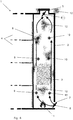
- FIG. 1 and 2 possible embodiments for a system according to the invention for ventilation and / or smoke extraction of a lift shaft are shown in purely schematic representations, wherein in the figures different operating states, namely a ventilation operation (FIG. FIGS. 1 and 2 ), an air exchange operation ( Fig. 3 ) and a smoke extraction plant ( FIG. 4 ) are shown.
- the figures each show a building section 1 with an elevator shaft 2 and an elevator car 3 which can be moved vertically in the latter.
- the elevator shaft 2 connects a plurality of elevator levels 4 located in different fire sections of the building, which can be approached by the elevator car 3.
- a vertically or horizontally mounted exhaust air and smoke extraction duct 5 which connects the elevator shaft 2 to the outside, with the ambient air located outside the building.
- the exhaust air and smoke extraction duct 5 is equipped with a closure element 6, by means of which it can be closed, which in an open position releases the connection of the elevator shaft 2 to the outside, outside the building.
- a supply air duct 7 is provided for supplying fresh air not contaminated from outside the building, which is likewise provided with a closure element 8 and can be closed by this.
- One or both of the closure elements 6 and 8 may be lamella flaps.
- Variants shown are arranged on two opposite sides of the elevator shaft 2 on the respective shaft wall fan 9, 10 in different vertical height positions.
- the fans 9 arranged on a first side and the fans 10 arranged on a second side opposite the first side are in each case arranged in pairs at the same height.
- three fans 9 are provided on the first side and three fans 10 on the second side in this example, a respective fan 9, 10 in the region of the shaft head, a fan 9, 10 in the region of a lowermost elevator stage and a fan 9, 10 in an intermediate middle section.
- the number of fans can be chosen freely, depends in particular on the dimensions, ie the height, but also the width and depth of the elevator shaft 2.
- the fans 9, 10 are thus - corresponding to the required number - over the entire shaft length mounted on two different shaft walls.
- These further fans 13, 14 are in each case arranged with the airs 9, 10 arranged on the same side to a first fan group (with the fans 9, 13) on the first side and a second fan group (with the fans 10, 14) on the second Page summarized.
- a variant can be selected in which only the fans 13, 14 on the elevator car, but not the fans 9, 10 are present on the shaft wall.
- FIG. 2 also shows a further fan 15, which can be an air exchange opening of the elevator car 3, for example, in the cabin ceiling, arranged and operated to promote air exchange between the interior of the elevator car 3 and the elevator shaft 2.
- a further fan 15 can be an air exchange opening of the elevator car 3, for example, in the cabin ceiling, arranged and operated to promote air exchange between the interior of the elevator car 3 and the elevator shaft 2.
- the shutter members 6, 8 are motor-driven for opening and closing, and the associated drive motors (not shown), as well as the fans 9, 10, 13, 14, are connected to a controller (not shown). Furthermore, sensors (not shown) are provided, the various parameters, in particular the air quality of the air and / or the air temperature in the elevator car 3, the air quality of the air and / or the air temperature and / or the humidity in the elevator shaft 2 and smoke in the elevator shaft 2 can monitor. These sensors are also connected to the controller.
- the ventilation, the air exchange or the smoke removal of the elevator shaft 2 are initiated and operated by the controller via various processes:
- Fig. 1 The procedure for the ventilation is in Fig. 1 and also in Fig. 2 shown.
- ventilation of the elevator car 3 is recognized as necessary, for example in the event of an elevator disturbance with persons trapped in the elevator car 3, it can be assumed that the elevator car 3 is naturally ventilated by air flowing past the car and shaft walls.
- About the in the floor and roof area of the elevator car 3 compulsory openings arises in the presence of air flow outside the elevator car 3, a sufficient permanent air exchange.
- fan 15 which also in a design variant according to Fig. 1 may be present, additionally transported.
- the fans 9, 10, 13, 14 together build a, in the figures 1 and 2 indicated by the arrows, circulating in a circle circulation of air in the elevator shaft 2, which then also provides for a Heilaustauch in the elevator car 3.
- the elevator car 3 can be ventilated with supply air of adequate air quality for a long time for the safety of the elevator users to ensure the well-being of the persons included until their release. If the volume of air in the elevator car 3 is already consumed after a very short time, then the volume of the elevator shaft 2, intelligently used for cabin ventilation, provides a generally sufficiently large air reserve for the prolonged ventilation of the elevator car 3 to the liberation of trapped persons. If the air in the elevator shaft 2 is insufficient, as described above, air exchange with the external environment is initiated by opening the shutter members 6, 8.
- the fan 9 (or alternatively or the fan 13) operated with opposite flow directions, ie are reversible in the conveying direction and with regard to the adjustment of the conveying direction controlled by the controller.
- the air quality of the supply air which flows with open closure element 8 via the supply air duct 7 in the elevator shaft 2, can be - tested both in the smoke extraction and in the ventilation or in the air exchange operation via a corresponding sensor. If the air quality of this supply air does not correspond to the limit values left in the control, it may then be at the controller's discretion to move the closure element 8 into the closed position and to close the supply air duct 7 in order to prevent contaminated air from entering the elevator shaft 2 ,
Landscapes
- Engineering & Computer Science (AREA)
- Mechanical Engineering (AREA)
- Chemical & Material Sciences (AREA)
- Combustion & Propulsion (AREA)
- General Engineering & Computer Science (AREA)
- Civil Engineering (AREA)
- Structural Engineering (AREA)
- Lift-Guide Devices, And Elevator Ropes And Cables (AREA)
- Maintenance And Inspection Apparatuses For Elevators (AREA)
- Cage And Drive Apparatuses For Elevators (AREA)
Applications Claiming Priority (1)
| Application Number | Priority Date | Filing Date | Title |
|---|---|---|---|
| DE202016101528.6U DE202016101528U1 (de) | 2016-03-21 | 2016-03-21 | Aufzugsschachtbelüftung und - entrauchung |
Publications (2)
| Publication Number | Publication Date |
|---|---|
| EP3222575A1 true EP3222575A1 (fr) | 2017-09-27 |
| EP3222575B1 EP3222575B1 (fr) | 2021-10-13 |
Family
ID=57110842
Family Applications (1)
| Application Number | Title | Priority Date | Filing Date |
|---|---|---|---|
| EP17158925.2A Active EP3222575B1 (fr) | 2016-03-21 | 2017-03-02 | Systeme et procédé pour l'aération et l'évacuation des fumées dans une cage d'ascenseur |
Country Status (2)
| Country | Link |
|---|---|
| EP (1) | EP3222575B1 (fr) |
| DE (1) | DE202016101528U1 (fr) |
Families Citing this family (7)
| Publication number | Priority date | Publication date | Assignee | Title |
|---|---|---|---|---|
| CN116045408A (zh) * | 2017-04-28 | 2023-05-02 | 苏州江南嘉捷电梯有限公司 | 一种电梯井道通风调压装置 |
| DE202017103267U1 (de) | 2017-05-31 | 2017-07-28 | Schako Klima Luft Ferdinand Schad Kg | Vorrichtung zum kontrollierten Öffnen und/oder Schliessen einer Öffnung |
| DE102017111921A1 (de) | 2017-05-31 | 2018-12-06 | Schako Klima Luft Ferdinand Schad Kg | Vorrichtung zum kontrollierten Öffnen und/oder Schliessen einer Öffnung |
| US11598540B2 (en) | 2019-03-06 | 2023-03-07 | The Board Of Regents Of The University Of Oklahoma | Apparatus and method for improving air quality in street canyons |
| CN110077935B (zh) * | 2019-04-26 | 2020-07-17 | 福建省特种设备检验研究院 | 一种观光电梯井道通风防晒系统的使用方法 |
| CN112758792A (zh) * | 2020-12-11 | 2021-05-07 | 中国计量大学 | 一种具有调节气动性出风口的电梯井道及其优化方法 |
| CN113071972B (zh) * | 2021-03-12 | 2022-05-27 | 日立电梯(上海)有限公司 | 一种超高速电梯井道气压调节方法和装置 |
Citations (4)
| Publication number | Priority date | Publication date | Assignee | Title |
|---|---|---|---|---|
| DE202006012724U1 (de) | 2006-08-17 | 2006-12-07 | Btr Brandschutz-Technik Und Rauchabzug Gmbh | Vorrichtung zur Aufzugsschacht-Entrauchung |
| EP1890956B1 (fr) | 2005-06-13 | 2008-09-03 | Royal AFC S.A. | Procédé et système de gestion d'énergie thermique dans un bâtiment avec gaine pour installations de levage |
| KR100902635B1 (ko) * | 2007-08-24 | 2009-06-15 | 조병남 | 계단실 또는 엘리베이터샤프트를 이용한 다층 건물 통풍시스템 |
| WO2016034415A1 (fr) * | 2014-09-05 | 2016-03-10 | Swiss Raltec Gmbh | Immeuble de grande taille comprenant n étages et un puits d'évacuation |
Family Cites Families (8)
| Publication number | Priority date | Publication date | Assignee | Title |
|---|---|---|---|---|
| US3817161A (en) * | 1972-10-26 | 1974-06-18 | N Koplon | Smoke protection system |
| US4592270A (en) * | 1984-07-16 | 1986-06-03 | Vener Alvin S | Smoke and fire protection system for elevators |
| JPH0796431B2 (ja) * | 1989-08-25 | 1995-10-18 | 三機工業株式会社 | クリーンルーム用エレベータ設備 |
| US5718627A (en) * | 1997-02-03 | 1998-02-17 | Wicks; Edward A. | System and method for smoke free elevator shaft |
| DE19848736B4 (de) * | 1998-10-22 | 2004-11-11 | Horch, Fabian | Rauchschutzeinrichtung für Treppenräume oder dergleichen |
| CN201043105Y (zh) * | 2007-04-13 | 2008-04-02 | 黄进军 | 可自行换气的垂直升降井式电梯 |
| CN201575553U (zh) * | 2009-10-21 | 2010-09-08 | 江苏省电力公司吴江市供电公司 | 利用电梯升降改善室内公共场所空气质量的装置 |
| CN102514998A (zh) * | 2011-12-12 | 2012-06-27 | 天津市建筑设计院 | 利用风能通风的电梯竖井及其电梯通风方法 |
-
2016
- 2016-03-21 DE DE202016101528.6U patent/DE202016101528U1/de active Active
-
2017
- 2017-03-02 EP EP17158925.2A patent/EP3222575B1/fr active Active
Patent Citations (4)
| Publication number | Priority date | Publication date | Assignee | Title |
|---|---|---|---|---|
| EP1890956B1 (fr) | 2005-06-13 | 2008-09-03 | Royal AFC S.A. | Procédé et système de gestion d'énergie thermique dans un bâtiment avec gaine pour installations de levage |
| DE202006012724U1 (de) | 2006-08-17 | 2006-12-07 | Btr Brandschutz-Technik Und Rauchabzug Gmbh | Vorrichtung zur Aufzugsschacht-Entrauchung |
| KR100902635B1 (ko) * | 2007-08-24 | 2009-06-15 | 조병남 | 계단실 또는 엘리베이터샤프트를 이용한 다층 건물 통풍시스템 |
| WO2016034415A1 (fr) * | 2014-09-05 | 2016-03-10 | Swiss Raltec Gmbh | Immeuble de grande taille comprenant n étages et un puits d'évacuation |
Also Published As
| Publication number | Publication date |
|---|---|
| DE202016101528U1 (de) | 2016-09-20 |
| EP3222575B1 (fr) | 2021-10-13 |
Similar Documents
| Publication | Publication Date | Title |
|---|---|---|
| EP3222575B1 (fr) | Systeme et procédé pour l'aération et l'évacuation des fumées dans une cage d'ascenseur | |
| EP3222574B1 (fr) | Système pour l'aération et l'évacuation des fumées dans une cage d'ascenseur | |
| EP2337912B1 (fr) | Immeuble avec une cage d'escalier et un puits d'aération | |
| DE2430592A1 (de) | Feuer-sicherheitssystem | |
| EP3189195B1 (fr) | Immeuble de grande taille comprenant n étages et un puits d'évacuation | |
| DE202016101525U1 (de) | Aufzugsschachtbelüftung und -entrauchung | |
| DE2613598A1 (de) | Feuer-sicherheitssystem | |
| DE202016101524U1 (de) | Aufzugsschachtbelüftung und -entrauchung | |
| EP1004536B1 (fr) | Méthode de contrôle pour ascenseurs en cas d'incendie ou de dangers similaires | |
| DE102015111678B4 (de) | Rauchschutzdruckanlage für ein Gebäude und Verfahren zum Rauchfreihalten | |
| DE10240745A1 (de) | Vorrichtung und Verfahren zur Verhinderung des Übergangs von Rauch- und/oder Brandgasen zwischen aneinander grenzenden Raumabschnitten in Gebäuden | |
| DE19841540B4 (de) | Anordnung und Verfahren zur Druckbelüftung von sicherheitsrelevanten Teilen eines Gebäudes | |
| DE1961837C3 (de) | Anordnung zur Rauchabführung im Brandfall bei vielgeschossigen Häusern mit innenliegendem Treppenhaus | |
| DE19856193C2 (de) | Verfahren zur Sicherung von Gebäudeteilen im Brandfall sowie Rauchschutzeinrichtung | |
| DE102007011428B4 (de) | Steuereinheit für eine Rauch- und Wärmeabzugsanlage eines Gebäudes | |
| EP3409632A2 (fr) | Dispositif de commande d'ouverture et/ou de fermeture contrôlées d'une ouverture | |
| EP3078918B1 (fr) | Installation de pression différentielle hybride de protection contre la fumée et procédé pour maintenir une pression différentielle | |
| DE202017103267U1 (de) | Vorrichtung zum kontrollierten Öffnen und/oder Schliessen einer Öffnung | |
| EP3473945A1 (fr) | Installation pare-fumées et procédé de fonctionnement d'une installation pare-fumées | |
| DE19814484A1 (de) | Verfahren und Vorrichtung zur Trennung von Raumbereichen mit unterschiedlichen Luftzusammensetzungen, insbesondere zur Rauchfreihaltung von Sicherheitsräumen in Gebäuden | |
| EP2505735B1 (fr) | Installation pressurisée de protection contre la fumée et procédé de maintien sans fumée d'une sortie de secours | |
| EP3853425A1 (fr) | Bâtiment à plusieurs étages comprenant des issues d'accès et de secours sûres en cas d'incendie | |
| EP4095082A1 (fr) | Système d'aération pour une cabine d'ascenseur, cabine d'ascenseur et procédé d'aération d'une cabine d'ascenseur | |
| EP2149534A1 (fr) | Installation d'ascenseur | |
| EP4357689A1 (fr) | Système et procédé de libération de fumée d'une liaison d'accès verticale d'un bâtiment à plusieurs étages |
Legal Events
| Date | Code | Title | Description |
|---|---|---|---|
| PUAI | Public reference made under article 153(3) epc to a published international application that has entered the european phase |
Free format text: ORIGINAL CODE: 0009012 |
|
| STAA | Information on the status of an ep patent application or granted ep patent |
Free format text: STATUS: THE APPLICATION HAS BEEN PUBLISHED |
|
| AK | Designated contracting states |
Kind code of ref document: A1 Designated state(s): AL AT BE BG CH CY CZ DE DK EE ES FI FR GB GR HR HU IE IS IT LI LT LU LV MC MK MT NL NO PL PT RO RS SE SI SK SM TR |
|
| AX | Request for extension of the european patent |
Extension state: BA ME |
|
| STAA | Information on the status of an ep patent application or granted ep patent |
Free format text: STATUS: REQUEST FOR EXAMINATION WAS MADE |
|
| 17P | Request for examination filed |
Effective date: 20171101 |
|
| RBV | Designated contracting states (corrected) |
Designated state(s): AL AT BE BG CH CY CZ DE DK EE ES FI FR GB GR HR HU IE IS IT LI LT LU LV MC MK MT NL NO PL PT RO RS SE SI SK SM TR |
|
| STAA | Information on the status of an ep patent application or granted ep patent |
Free format text: STATUS: EXAMINATION IS IN PROGRESS |
|
| STAA | Information on the status of an ep patent application or granted ep patent |
Free format text: STATUS: EXAMINATION IS IN PROGRESS |
|
| 17Q | First examination report despatched |
Effective date: 20210111 |
|
| GRAP | Despatch of communication of intention to grant a patent |
Free format text: ORIGINAL CODE: EPIDOSNIGR1 |
|
| STAA | Information on the status of an ep patent application or granted ep patent |
Free format text: STATUS: GRANT OF PATENT IS INTENDED |
|
| INTG | Intention to grant announced |
Effective date: 20210727 |
|
| RAP3 | Party data changed (applicant data changed or rights of an application transferred) |
Owner name: BLUEKIT FACTORY GMBH |
|
| GRAS | Grant fee paid |
Free format text: ORIGINAL CODE: EPIDOSNIGR3 |
|
| GRAA | (expected) grant |
Free format text: ORIGINAL CODE: 0009210 |
|
| STAA | Information on the status of an ep patent application or granted ep patent |
Free format text: STATUS: THE PATENT HAS BEEN GRANTED |
|
| AK | Designated contracting states |
Kind code of ref document: B1 Designated state(s): AL AT BE BG CH CY CZ DE DK EE ES FI FR GB GR HR HU IE IS IT LI LT LU LV MC MK MT NL NO PL PT RO RS SE SI SK SM TR |
|
| REG | Reference to a national code |
Ref country code: GB Ref legal event code: FG4D Free format text: NOT ENGLISH |
|
| REG | Reference to a national code |
Ref country code: CH Ref legal event code: EP |
|
| REG | Reference to a national code |
Ref country code: DE Ref legal event code: R096 Ref document number: 502017011698 Country of ref document: DE |
|
| REG | Reference to a national code |
Ref country code: IE Ref legal event code: FG4D Free format text: LANGUAGE OF EP DOCUMENT: GERMAN |
|
| REG | Reference to a national code |
Ref country code: AT Ref legal event code: REF Ref document number: 1438076 Country of ref document: AT Kind code of ref document: T Effective date: 20211115 |
|
| REG | Reference to a national code |
Ref country code: LT Ref legal event code: MG9D |
|
| REG | Reference to a national code |
Ref country code: NL Ref legal event code: MP Effective date: 20211013 |
|
| PG25 | Lapsed in a contracting state [announced via postgrant information from national office to epo] |
Ref country code: RS Free format text: LAPSE BECAUSE OF FAILURE TO SUBMIT A TRANSLATION OF THE DESCRIPTION OR TO PAY THE FEE WITHIN THE PRESCRIBED TIME-LIMIT Effective date: 20211013 Ref country code: LT Free format text: LAPSE BECAUSE OF FAILURE TO SUBMIT A TRANSLATION OF THE DESCRIPTION OR TO PAY THE FEE WITHIN THE PRESCRIBED TIME-LIMIT Effective date: 20211013 Ref country code: FI Free format text: LAPSE BECAUSE OF FAILURE TO SUBMIT A TRANSLATION OF THE DESCRIPTION OR TO PAY THE FEE WITHIN THE PRESCRIBED TIME-LIMIT Effective date: 20211013 Ref country code: BG Free format text: LAPSE BECAUSE OF FAILURE TO SUBMIT A TRANSLATION OF THE DESCRIPTION OR TO PAY THE FEE WITHIN THE PRESCRIBED TIME-LIMIT Effective date: 20220113 |
|
| PG25 | Lapsed in a contracting state [announced via postgrant information from national office to epo] |
Ref country code: IS Free format text: LAPSE BECAUSE OF FAILURE TO SUBMIT A TRANSLATION OF THE DESCRIPTION OR TO PAY THE FEE WITHIN THE PRESCRIBED TIME-LIMIT Effective date: 20220213 Ref country code: SE Free format text: LAPSE BECAUSE OF FAILURE TO SUBMIT A TRANSLATION OF THE DESCRIPTION OR TO PAY THE FEE WITHIN THE PRESCRIBED TIME-LIMIT Effective date: 20211013 Ref country code: PT Free format text: LAPSE BECAUSE OF FAILURE TO SUBMIT A TRANSLATION OF THE DESCRIPTION OR TO PAY THE FEE WITHIN THE PRESCRIBED TIME-LIMIT Effective date: 20220214 Ref country code: PL Free format text: LAPSE BECAUSE OF FAILURE TO SUBMIT A TRANSLATION OF THE DESCRIPTION OR TO PAY THE FEE WITHIN THE PRESCRIBED TIME-LIMIT Effective date: 20211013 Ref country code: NO Free format text: LAPSE BECAUSE OF FAILURE TO SUBMIT A TRANSLATION OF THE DESCRIPTION OR TO PAY THE FEE WITHIN THE PRESCRIBED TIME-LIMIT Effective date: 20220113 Ref country code: NL Free format text: LAPSE BECAUSE OF FAILURE TO SUBMIT A TRANSLATION OF THE DESCRIPTION OR TO PAY THE FEE WITHIN THE PRESCRIBED TIME-LIMIT Effective date: 20211013 Ref country code: LV Free format text: LAPSE BECAUSE OF FAILURE TO SUBMIT A TRANSLATION OF THE DESCRIPTION OR TO PAY THE FEE WITHIN THE PRESCRIBED TIME-LIMIT Effective date: 20211013 Ref country code: HR Free format text: LAPSE BECAUSE OF FAILURE TO SUBMIT A TRANSLATION OF THE DESCRIPTION OR TO PAY THE FEE WITHIN THE PRESCRIBED TIME-LIMIT Effective date: 20211013 Ref country code: GR Free format text: LAPSE BECAUSE OF FAILURE TO SUBMIT A TRANSLATION OF THE DESCRIPTION OR TO PAY THE FEE WITHIN THE PRESCRIBED TIME-LIMIT Effective date: 20220114 Ref country code: ES Free format text: LAPSE BECAUSE OF FAILURE TO SUBMIT A TRANSLATION OF THE DESCRIPTION OR TO PAY THE FEE WITHIN THE PRESCRIBED TIME-LIMIT Effective date: 20211013 |
|
| REG | Reference to a national code |
Ref country code: DE Ref legal event code: R097 Ref document number: 502017011698 Country of ref document: DE |
|
| PG25 | Lapsed in a contracting state [announced via postgrant information from national office to epo] |
Ref country code: SM Free format text: LAPSE BECAUSE OF FAILURE TO SUBMIT A TRANSLATION OF THE DESCRIPTION OR TO PAY THE FEE WITHIN THE PRESCRIBED TIME-LIMIT Effective date: 20211013 Ref country code: SK Free format text: LAPSE BECAUSE OF FAILURE TO SUBMIT A TRANSLATION OF THE DESCRIPTION OR TO PAY THE FEE WITHIN THE PRESCRIBED TIME-LIMIT Effective date: 20211013 Ref country code: RO Free format text: LAPSE BECAUSE OF FAILURE TO SUBMIT A TRANSLATION OF THE DESCRIPTION OR TO PAY THE FEE WITHIN THE PRESCRIBED TIME-LIMIT Effective date: 20211013 Ref country code: EE Free format text: LAPSE BECAUSE OF FAILURE TO SUBMIT A TRANSLATION OF THE DESCRIPTION OR TO PAY THE FEE WITHIN THE PRESCRIBED TIME-LIMIT Effective date: 20211013 Ref country code: DK Free format text: LAPSE BECAUSE OF FAILURE TO SUBMIT A TRANSLATION OF THE DESCRIPTION OR TO PAY THE FEE WITHIN THE PRESCRIBED TIME-LIMIT Effective date: 20211013 Ref country code: CZ Free format text: LAPSE BECAUSE OF FAILURE TO SUBMIT A TRANSLATION OF THE DESCRIPTION OR TO PAY THE FEE WITHIN THE PRESCRIBED TIME-LIMIT Effective date: 20211013 |
|
| PLBE | No opposition filed within time limit |
Free format text: ORIGINAL CODE: 0009261 |
|
| STAA | Information on the status of an ep patent application or granted ep patent |
Free format text: STATUS: NO OPPOSITION FILED WITHIN TIME LIMIT |
|
| 26N | No opposition filed |
Effective date: 20220714 |
|
| REG | Reference to a national code |
Ref country code: DE Ref legal event code: R119 Ref document number: 502017011698 Country of ref document: DE |
|
| PG25 | Lapsed in a contracting state [announced via postgrant information from national office to epo] |
Ref country code: MC Free format text: LAPSE BECAUSE OF FAILURE TO SUBMIT A TRANSLATION OF THE DESCRIPTION OR TO PAY THE FEE WITHIN THE PRESCRIBED TIME-LIMIT Effective date: 20211013 Ref country code: AL Free format text: LAPSE BECAUSE OF FAILURE TO SUBMIT A TRANSLATION OF THE DESCRIPTION OR TO PAY THE FEE WITHIN THE PRESCRIBED TIME-LIMIT Effective date: 20211013 |
|
| REG | Reference to a national code |
Ref country code: CH Ref legal event code: PL |
|
| GBPC | Gb: european patent ceased through non-payment of renewal fee |
Effective date: 20220302 |
|
| PG25 | Lapsed in a contracting state [announced via postgrant information from national office to epo] |
Ref country code: SI Free format text: LAPSE BECAUSE OF FAILURE TO SUBMIT A TRANSLATION OF THE DESCRIPTION OR TO PAY THE FEE WITHIN THE PRESCRIBED TIME-LIMIT Effective date: 20211013 |
|
| REG | Reference to a national code |
Ref country code: BE Ref legal event code: MM Effective date: 20220331 |
|
| PG25 | Lapsed in a contracting state [announced via postgrant information from national office to epo] |
Ref country code: LU Free format text: LAPSE BECAUSE OF NON-PAYMENT OF DUE FEES Effective date: 20220302 Ref country code: LI Free format text: LAPSE BECAUSE OF NON-PAYMENT OF DUE FEES Effective date: 20220331 Ref country code: IE Free format text: LAPSE BECAUSE OF NON-PAYMENT OF DUE FEES Effective date: 20220302 Ref country code: GB Free format text: LAPSE BECAUSE OF NON-PAYMENT OF DUE FEES Effective date: 20220302 Ref country code: FR Free format text: LAPSE BECAUSE OF NON-PAYMENT OF DUE FEES Effective date: 20220331 Ref country code: DE Free format text: LAPSE BECAUSE OF NON-PAYMENT OF DUE FEES Effective date: 20221001 Ref country code: CH Free format text: LAPSE BECAUSE OF NON-PAYMENT OF DUE FEES Effective date: 20220331 |
|
| PG25 | Lapsed in a contracting state [announced via postgrant information from national office to epo] |
Ref country code: BE Free format text: LAPSE BECAUSE OF NON-PAYMENT OF DUE FEES Effective date: 20220331 |
|
| REG | Reference to a national code |
Ref country code: AT Ref legal event code: MM01 Ref document number: 1438076 Country of ref document: AT Kind code of ref document: T Effective date: 20220302 |
|
| PG25 | Lapsed in a contracting state [announced via postgrant information from national office to epo] |
Ref country code: IT Free format text: LAPSE BECAUSE OF FAILURE TO SUBMIT A TRANSLATION OF THE DESCRIPTION OR TO PAY THE FEE WITHIN THE PRESCRIBED TIME-LIMIT Effective date: 20211013 |
|
| PG25 | Lapsed in a contracting state [announced via postgrant information from national office to epo] |
Ref country code: AT Free format text: LAPSE BECAUSE OF NON-PAYMENT OF DUE FEES Effective date: 20220302 |
|
| PG25 | Lapsed in a contracting state [announced via postgrant information from national office to epo] |
Ref country code: HU Free format text: LAPSE BECAUSE OF FAILURE TO SUBMIT A TRANSLATION OF THE DESCRIPTION OR TO PAY THE FEE WITHIN THE PRESCRIBED TIME-LIMIT; INVALID AB INITIO Effective date: 20170302 |
|
| PG25 | Lapsed in a contracting state [announced via postgrant information from national office to epo] |
Ref country code: MK Free format text: LAPSE BECAUSE OF FAILURE TO SUBMIT A TRANSLATION OF THE DESCRIPTION OR TO PAY THE FEE WITHIN THE PRESCRIBED TIME-LIMIT Effective date: 20211013 Ref country code: CY Free format text: LAPSE BECAUSE OF FAILURE TO SUBMIT A TRANSLATION OF THE DESCRIPTION OR TO PAY THE FEE WITHIN THE PRESCRIBED TIME-LIMIT Effective date: 20211013 |