EP3222575A1 - Device and menthod for elevator shaft ventilation and purging - Google Patents
Device and menthod for elevator shaft ventilation and purging Download PDFInfo
- Publication number
- EP3222575A1 EP3222575A1 EP17158925.2A EP17158925A EP3222575A1 EP 3222575 A1 EP3222575 A1 EP 3222575A1 EP 17158925 A EP17158925 A EP 17158925A EP 3222575 A1 EP3222575 A1 EP 3222575A1
- Authority
- EP
- European Patent Office
- Prior art keywords
- elevator shaft
- air
- elevator
- shaft
- fans
- Prior art date
- Legal status (The legal status is an assumption and is not a legal conclusion. Google has not performed a legal analysis and makes no representation as to the accuracy of the status listed.)
- Granted
Links
- 238000009423 ventilation Methods 0.000 title claims abstract description 52
- 238000010926 purge Methods 0.000 title 1
- 239000000779 smoke Substances 0.000 claims abstract description 83
- 238000000605 extraction Methods 0.000 claims abstract description 55
- 238000000034 method Methods 0.000 claims abstract description 11
- 230000002441 reversible effect Effects 0.000 claims description 5
- 241000446313 Lamella Species 0.000 claims description 3
- 239000003570 air Substances 0.000 description 138
- UGFAIRIUMAVXCW-UHFFFAOYSA-N Carbon monoxide Chemical compound [O+]#[C-] UGFAIRIUMAVXCW-UHFFFAOYSA-N 0.000 description 6
- 229910002091 carbon monoxide Inorganic materials 0.000 description 6
- 238000011161 development Methods 0.000 description 4
- 230000018109 developmental process Effects 0.000 description 4
- CURLTUGMZLYLDI-UHFFFAOYSA-N Carbon dioxide Chemical compound O=C=O CURLTUGMZLYLDI-UHFFFAOYSA-N 0.000 description 2
- 238000013461 design Methods 0.000 description 2
- 238000001514 detection method Methods 0.000 description 2
- 238000005399 mechanical ventilation Methods 0.000 description 2
- 239000012855 volatile organic compound Substances 0.000 description 2
- 230000003213 activating effect Effects 0.000 description 1
- 238000005273 aeration Methods 0.000 description 1
- 239000012080 ambient air Substances 0.000 description 1
- 229910002092 carbon dioxide Inorganic materials 0.000 description 1
- 239000001569 carbon dioxide Substances 0.000 description 1
- 238000010276 construction Methods 0.000 description 1
- 238000001816 cooling Methods 0.000 description 1
- 238000009795 derivation Methods 0.000 description 1
- 238000010790 dilution Methods 0.000 description 1
- 239000012895 dilution Substances 0.000 description 1
- 230000000694 effects Effects 0.000 description 1
- 239000007789 gas Substances 0.000 description 1
- 238000010438 heat treatment Methods 0.000 description 1
- 238000009434 installation Methods 0.000 description 1
- 238000012423 maintenance Methods 0.000 description 1
- 238000012544 monitoring process Methods 0.000 description 1
- 230000002035 prolonged effect Effects 0.000 description 1
- 229910052704 radon Inorganic materials 0.000 description 1
- SYUHGPGVQRZVTB-UHFFFAOYSA-N radon atom Chemical compound [Rn] SYUHGPGVQRZVTB-UHFFFAOYSA-N 0.000 description 1
- 230000000630 rising effect Effects 0.000 description 1
- 239000000243 solution Substances 0.000 description 1
- 238000010025 steaming Methods 0.000 description 1
- 238000012360 testing method Methods 0.000 description 1
- 238000013022 venting Methods 0.000 description 1
- 230000036642 wellbeing Effects 0.000 description 1
Images


Classifications
-
- F—MECHANICAL ENGINEERING; LIGHTING; HEATING; WEAPONS; BLASTING
- F24—HEATING; RANGES; VENTILATING
- F24F—AIR-CONDITIONING; AIR-HUMIDIFICATION; VENTILATION; USE OF AIR CURRENTS FOR SCREENING
- F24F11/00—Control or safety arrangements
- F24F11/0001—Control or safety arrangements for ventilation
-
- B—PERFORMING OPERATIONS; TRANSPORTING
- B66—HOISTING; LIFTING; HAULING
- B66B—ELEVATORS; ESCALATORS OR MOVING WALKWAYS
- B66B11/00—Main component parts of lifts in, or associated with, buildings or other structures
- B66B11/0005—Constructional features of hoistways
-
- F—MECHANICAL ENGINEERING; LIGHTING; HEATING; WEAPONS; BLASTING
- F24—HEATING; RANGES; VENTILATING
- F24F—AIR-CONDITIONING; AIR-HUMIDIFICATION; VENTILATION; USE OF AIR CURRENTS FOR SCREENING
- F24F7/00—Ventilation
- F24F7/04—Ventilation with ducting systems, e.g. by double walls; with natural circulation
- F24F7/06—Ventilation with ducting systems, e.g. by double walls; with natural circulation with forced air circulation, e.g. by fan positioning of a ventilator in or against a conduit
-
- F—MECHANICAL ENGINEERING; LIGHTING; HEATING; WEAPONS; BLASTING
- F24—HEATING; RANGES; VENTILATING
- F24F—AIR-CONDITIONING; AIR-HUMIDIFICATION; VENTILATION; USE OF AIR CURRENTS FOR SCREENING
- F24F11/00—Control or safety arrangements
- F24F11/30—Control or safety arrangements for purposes related to the operation of the system, e.g. for safety or monitoring
- F24F11/32—Responding to malfunctions or emergencies
- F24F11/33—Responding to malfunctions or emergencies to fire, excessive heat or smoke
Definitions
- the present invention relates to a system and also to a method for ventilating and / or de-smoking a lift shaft, in particular with elevator shafts, which are located in different elevator levels and are separate fire compartments of a building, which is bounded by vertical shaft walls.
- This opening is generally located in the elevator shaft head or, if present, in an elevator machinery room above it and leads directly outside the building envelope.
- Such solutions are disclosed, for example, in US Pat EP 1 890 956 B1 (with purely passive operated, natural ventilation system) or in the DE 20 2006 012 724 U1 (there with a fan used for the removal of smoke outside the building in an otherwise purely passive operated exhaust vent).
- Lift shaft ventilation and smoke extraction systems which control the natural ventilation and smoke extraction of the elevator shaft via a window or a flap in the shaft head or in the engine room, are known from the prior art. Although such a system could be used in the elevator shaft of the property described, it can not contribute to the safe operation of the elevator system due to the described lack of thermal in the elevator shaft, or not ensure the safety of the elevator users.
- the fans arranged on opposite sides in the elevator shaft can be arranged in particular in the elevator shaft in the area of the shaft walls on opposite sides. But they can also be arranged on opposite positions on two cabin walls of the elevator car.
- a hybrid form is also conceivable in which fans are arranged both on the cabin walls and in the area of the shaft walls, in which case one side of the elevator shaft has a zone of the shaft walls as well as a region of the cabin walls located there combined number of fans is arranged, on the opposite side of a fan group is formed by arranged there in the region of the shaft walls and the cabin walls fan.
- the control is set up to control the fans in such a way when a need for ventilation of the elevator car and / or the elevator shaft is known that fans arranged on a first of the two sides convey air in the elevator shaft in an upward conveying direction (this can then be done, for example, by the above-mentioned first fan group), on a second of the two sides in the elevator shaft arranged fan (eg also by the example second fan group) promote air in the elevator shaft in a downward conveying direction, and the controller continues to do so is arranged, upon detecting a need for a smoke removal of the hoistway to control the drive motor for the second closure element in such a way that it opens the exhaust and smoke extraction duct, and to control the fans in a manner to operate that all airs arranged in the elevator shaft Air in the elevator shaft in an equally directed conveying direction in the direction of a vertical or horizontal position in which the exhaust air and smoke extraction channel opens into the elevator shaft, promote.
- the fresh air volume in the elevator shaft is sufficient in order to supply the elevator car with fresh air for a sufficiently long service life from this reservoir.
- the supply air duct open by moving the closure element associated therewith and can flow fresh air.
- the exhaust air and smoke extraction duct is opened to dissipate excess air over it.
- the fans can be operated in opposite directions in particular in the manner described above, in order to maintain the air circulation in this case upright and to distribute distributed fresh air accordingly, to push air to be discharged from the exhaust air and smoke extraction duct.
- the fans are all operated in a conveying direction, ie run the fans of either side compared to the case of pure ventilation in the opposite direction to so to push the air with the smoke in one direction and in the direction of the then opened exhaust and smoke extraction duct to derive the smoke there from the elevator shaft.
- the supply air duct can be opened in order to track over this fresh and smoke-free air into the elevator shaft, there to provide fresh air, at least for a dilution of the smoke.
- opposite sides on which the fans are arranged according to the invention, for example attachment positions on two opposite vertical shaft walls or on two opposite cabin walls are meant here.
- positions on two adjoining shaft walls or cabin walls may be “opposite one another", for example along a diagonal of a shaft cross-section opposite each other. It is important here that the opposing positions are spaced apart over a wide distance of the cross section of the elevator shaft, so that on different sides of the elevator car, a corresponding air flow (in particular for the aeration and an outflow) is generated, thereby the desired To achieve flow conditions (circulation or air delivery to the exhaust air and smoke extraction duct).
- sensors can be used.
- Air quality sensors for monitoring the air quality in the elevator car and / or in the elevator shaft be smoke detectors or temperature sensors in the elevator car and / or in the elevator shaft.
- sensors which detect a movement of the elevator car or the presence of persons in the cabin and / or in the elevator shaft can be considered as sensors in the context of this invention.
- a plurality of fans may be arranged, this - in particular evenly distributed over the height of the elevator shaft, or over the height of the elevator car in order to achieve the air flows to be achieved (circulation in the ventilation mode, directional discharge in the smoke extraction mode).
- the fans on the opposite sides can, but not necessarily, be arranged in pairs with at least one fan per side at the same height.
- the supply air is brought from a lower position in the elevator shaft, the exhaust air or the smoke are discharged at an upper position of the elevator shaft. Therefore, in particular the exhaust air and smoke extraction duct can open vertically above the supply air duct in the elevator shaft.
- the supply air duct may open into the elevator shaft in a shaft pit of the elevator shaft or in the area of a lowest elevator layer.
- the first and / or the second closure element may in particular be formed by a lamella closure. Such can be opened and closed with a large opening cross-section, while still saving space.
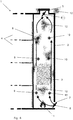
- FIG. 1 and 2 possible embodiments for a system according to the invention for ventilation and / or smoke extraction of a lift shaft are shown in purely schematic representations, wherein in the figures different operating states, namely a ventilation operation (FIG. FIGS. 1 and 2 ), an air exchange operation ( Fig. 3 ) and a smoke extraction plant ( FIG. 4 ) are shown.
- the figures each show a building section 1 with an elevator shaft 2 and an elevator car 3 which can be moved vertically in the latter.
- the elevator shaft 2 connects a plurality of elevator levels 4 located in different fire sections of the building, which can be approached by the elevator car 3.
- a vertically or horizontally mounted exhaust air and smoke extraction duct 5 which connects the elevator shaft 2 to the outside, with the ambient air located outside the building.
- the exhaust air and smoke extraction duct 5 is equipped with a closure element 6, by means of which it can be closed, which in an open position releases the connection of the elevator shaft 2 to the outside, outside the building.
- a supply air duct 7 is provided for supplying fresh air not contaminated from outside the building, which is likewise provided with a closure element 8 and can be closed by this.
- One or both of the closure elements 6 and 8 may be lamella flaps.
- Variants shown are arranged on two opposite sides of the elevator shaft 2 on the respective shaft wall fan 9, 10 in different vertical height positions.
- the fans 9 arranged on a first side and the fans 10 arranged on a second side opposite the first side are in each case arranged in pairs at the same height.
- three fans 9 are provided on the first side and three fans 10 on the second side in this example, a respective fan 9, 10 in the region of the shaft head, a fan 9, 10 in the region of a lowermost elevator stage and a fan 9, 10 in an intermediate middle section.
- the number of fans can be chosen freely, depends in particular on the dimensions, ie the height, but also the width and depth of the elevator shaft 2.
- the fans 9, 10 are thus - corresponding to the required number - over the entire shaft length mounted on two different shaft walls.
- These further fans 13, 14 are in each case arranged with the airs 9, 10 arranged on the same side to a first fan group (with the fans 9, 13) on the first side and a second fan group (with the fans 10, 14) on the second Page summarized.
- a variant can be selected in which only the fans 13, 14 on the elevator car, but not the fans 9, 10 are present on the shaft wall.
- FIG. 2 also shows a further fan 15, which can be an air exchange opening of the elevator car 3, for example, in the cabin ceiling, arranged and operated to promote air exchange between the interior of the elevator car 3 and the elevator shaft 2.
- a further fan 15 can be an air exchange opening of the elevator car 3, for example, in the cabin ceiling, arranged and operated to promote air exchange between the interior of the elevator car 3 and the elevator shaft 2.
- the shutter members 6, 8 are motor-driven for opening and closing, and the associated drive motors (not shown), as well as the fans 9, 10, 13, 14, are connected to a controller (not shown). Furthermore, sensors (not shown) are provided, the various parameters, in particular the air quality of the air and / or the air temperature in the elevator car 3, the air quality of the air and / or the air temperature and / or the humidity in the elevator shaft 2 and smoke in the elevator shaft 2 can monitor. These sensors are also connected to the controller.
- the ventilation, the air exchange or the smoke removal of the elevator shaft 2 are initiated and operated by the controller via various processes:
- Fig. 1 The procedure for the ventilation is in Fig. 1 and also in Fig. 2 shown.
- ventilation of the elevator car 3 is recognized as necessary, for example in the event of an elevator disturbance with persons trapped in the elevator car 3, it can be assumed that the elevator car 3 is naturally ventilated by air flowing past the car and shaft walls.
- About the in the floor and roof area of the elevator car 3 compulsory openings arises in the presence of air flow outside the elevator car 3, a sufficient permanent air exchange.
- fan 15 which also in a design variant according to Fig. 1 may be present, additionally transported.
- the fans 9, 10, 13, 14 together build a, in the figures 1 and 2 indicated by the arrows, circulating in a circle circulation of air in the elevator shaft 2, which then also provides for a Heilaustauch in the elevator car 3.
- the elevator car 3 can be ventilated with supply air of adequate air quality for a long time for the safety of the elevator users to ensure the well-being of the persons included until their release. If the volume of air in the elevator car 3 is already consumed after a very short time, then the volume of the elevator shaft 2, intelligently used for cabin ventilation, provides a generally sufficiently large air reserve for the prolonged ventilation of the elevator car 3 to the liberation of trapped persons. If the air in the elevator shaft 2 is insufficient, as described above, air exchange with the external environment is initiated by opening the shutter members 6, 8.
- the fan 9 (or alternatively or the fan 13) operated with opposite flow directions, ie are reversible in the conveying direction and with regard to the adjustment of the conveying direction controlled by the controller.
- the air quality of the supply air which flows with open closure element 8 via the supply air duct 7 in the elevator shaft 2, can be - tested both in the smoke extraction and in the ventilation or in the air exchange operation via a corresponding sensor. If the air quality of this supply air does not correspond to the limit values left in the control, it may then be at the controller's discretion to move the closure element 8 into the closed position and to close the supply air duct 7 in order to prevent contaminated air from entering the elevator shaft 2 ,
Abstract
Es werden ein System und ein Verfahren zum Belüften und/oder Entrauchen eines, insbesondere mit in unterschiedlichen Aufzugsebenen liegenden, getrennten Brandabschnitten eines Gebäudes in Verbindung stehenden, durch vertikale Schachtwände begrenzten Aufzugsschachts (2) mit darin vertikal verfahrbarer Aufzugskabine (3) offenbart. Dabei sind Lüfter vorgesehen (9, 10), von denen auf wenigstens zwei Seiten des Aufzugsschachtes je wenigstens zwei an unterschiedlichen vertikalen Positionen angeordnet sind. Über einen mit einem ersten Verschlusselement (8) verschließbaren Zuluftkanal (7) ist der Aufzugsschacht mit einem außerhalb des Gebäudes liegenden Außenbereich verbunden. Weiterhin ist ein verschließbarer Abluft- und Entrauchungskanal (5) vorgesehen, der den Aufzugsschacht (2) mit dem Außenbereich verbindendet. Über wenigstens einen Sensor wird eine Notwendigkeit einer Lüftung der Aufzugskabine (3) und/oder des Aufzugsschachtes (2) und/oder eine Notwendigkeit einer Entrauchung des Aufzugsschachts (2) und/oder eines Luftwechsels der Luft im Aufzugsschacht (2) erkannt. Wird eine Notwendigkeit für eine Lüftung der Aufzugskabine (3) und/oder des Aufzugsschachtes (2) erkannt, werden die Lüfter (9, 10) in einer Weise betrieben, dass auf einer ersten der beiden Seiten des Aufzugsschachts (2) angeordnete Lüfter (10) Luft in dem Aufzugsschacht (2) in einer aufwärts gerichteten Förderrichtung fördern, auf einer zweiten der beiden Seiten des Aufzugsschachts (2) angeordnete Lüfter (9) Luft in dem Aufzugsschacht (2) in einer abwärts gerichteten Förderrichtung fördern. Wird dagegen die Notwendigkeit für eine Entrauchung des Aufzugsschachts (2) und/oder eines Luftaustausches der Luft im Aufzugsschacht (2) festgestellt, wird der Abluft- und Entrauchungskanal (5) geöffnet, und werden die Lüfter (9, 10) in einer Weise betrieben, dass alle Lüfter (9, 10) Luft in dem Aufzugsschacht (2) in einer gleich gerichteten Förderrichtung in Richtung einer vertikalen oder horizontalen Position, in der der Abluft- und Entrauchungskanal (5) in den Aufzugsschacht (2) mündet, fördern.A system and a method are disclosed for ventilating and / or de-airing an elevator shaft (2), which is connected to separate vertical fire walls of a building and is located in different elevator levels, with elevator car (3) movable vertically through vertical shaft walls. In this case, fans are provided (9, 10), of which at least two sides of the elevator shaft are each arranged at least two at different vertical positions. The elevator shaft is connected to an outside area outside the building by means of a supply air duct (7) which can be closed by a first closure element (8). Furthermore, a closable exhaust air and smoke extraction duct (5) is provided, which connects the elevator shaft (2) with the outside area. A need for a ventilation of the elevator car (3) and / or the elevator shaft (2) and / or a need for smoke extraction of the elevator shaft (2) and / or air exchange in the elevator shaft (2) is detected by at least one sensor. If a need for a ventilation of the elevator car (3) and / or the elevator shaft (2) is detected, the fans (9, 10) are operated in such a way that fans (10) arranged on a first of the two sides of the elevator shaft (2) ) Promote air in the elevator shaft (2) in an upward conveying direction, on a second of the two sides of the elevator shaft (2) arranged fan (9) promote air in the elevator shaft (2) in a downward conveying direction. If, however, the need for smoke extraction of the elevator shaft (2) and / or an air exchange of the air in the elevator shaft (2) is established, the exhaust air and smoke extraction duct (5) is opened, and the fans (9, 10) are operated in a manner in that all fans (9, 10) convey air in the elevator shaft (2) in a direction of conveyance in the same direction in the direction of a vertical or horizontal position in which the exhaust air and smoke extraction duct (5) opens into the elevator shaft (2).
Description
Die vorliegende Erfindung betrifft ein System und auch ein Verfahren zum Belüften und/oder Entrauchen eines, insbesondere mit in unterschiedlichen Aufzugsebenen liegenden, getrennten Brandabschnitten eines Gebäudes in Verbindung stehenden, Aufzugsschachts, der durch vertikale Schachtwände begrenzt ist.The present invention relates to a system and also to a method for ventilating and / or de-smoking a lift shaft, in particular with elevator shafts, which are located in different elevator levels and are separate fire compartments of a building, which is bounded by vertical shaft walls.
Aufzugsschächte und Aufzugskabinen müssen zu belüften und in einem Brandfalle frei von Rauch zu halten sein. Erscheint die Erkennung von Rauch sowie der darauffolgende Bedarf von Rauchableitung im Aufzugsschacht trivial, so hängt die Erkennung eines Lüftungsbedarfs des Aufzugsschachtes bzw. der Aufzugskabine nach neuesten Erkenntnissen von vielen Parametern ab.Lift shafts and elevator cabins must be ventilated and kept free from smoke in case of fire. If the detection of smoke and the subsequent need for smoke extraction in the elevator shaft trivial, the detection of ventilation needs of the elevator shaft or the elevator car depends on the latest knowledge of many parameters.
Muss auf die Rauchableitung in einer Immobilie nur in seltenen Schadensfällen zurückgegriffen werden, so muss die Lüftung des Aufzugsschachtes je nach Nutzung der Aufzugsanlage und der Immobilie, in Abhängigkeit von Luftqualität, Lufttemperatur und Aufzugsstatus, in der Regel mehrfach im Laufe eines Tages erfolgen. Die bestbekannteste Notsituation liegt bei einer Aufzugsstörung mit Personeneinschluss vor. Nach dem aktuellen Stand der Technik wird davon ausgegangen, dass sowohl die Entrauchung als auch die Lüftung des Aufzugschachtes auf natürliche Art und Weise erfolgen können. Daher verfügen Aufzugsschächte generell über eine Öffnung über welche sowohl eine Lüftung des Schachtes und somit der Aufzugskabine, als auch im Brandfall eine Entrauchung des Schachtes durch natürliche Ventilation, d.h. rein passiv und ohne aktive Lüftung, gewährleistet sein soll. Diese Öffnung befindet sich generell im Aufzugsschachtkopf oder, falls vorhanden, in einem darüber gelegenen Aufzugsmaschinenraum und führt direkt nach außerhalb der Gebäudehülle. Offenbart sind solche Lösungen z.B. in der der
Dass die Ableitung von durch CO2, natürlich vorkommenden, flüchtigen organischen Stoffen (sog. "VOC") oder durch Rauch kontaminierter Luft nur dann gewährleistet sein kann, wenn gleichzeitig eine entsprechende Zufuhr von nicht kontaminierter Frischluft zur Verfügung steht, unterliegt den Gesetzen der Physik.The derivation of CO 2 , naturally occurring, volatile organic compounds (so-called "VOC") or air contaminated with smoke can only be guaranteed if at the same time a corresponding supply of uncontaminated fresh air is available, is subject to the laws of physics ,
Insbesondere Aufzugsanlagen in Geschäftsimmobilien fahren in der Regel verschiedene Aufzugsebenen an, welche sich in unterschiedlichen Brandabschnitten befinden. In solchen Immobilien darf die Raumluft vor den Aufzugsschachttüren beispielsweise aus sicherheitstechnischen Gründen nicht zur Zufuhr von nicht kontaminierter Frischluft in den Aufzugsschacht genutzt werden. Ebenfalls kann Luft aus den unteren Stockwerken einer Immobilie nur in den seltensten Fällen zur Lüftung des Aufzugsschachtes genutzt werden, da diese generell stärker durch Kohlenmonoxid (CO), z.B. aus einer unterhalb der Wohn- bzw. Gewerbeflächen in dem Gebäude gelegenen Tiefgarage oder aus einer in einem Kellerbereich des Gebäudes vorgesehenen Heizung, oder auch durch weitere Gase, wie z.B. Radon und Kohlendioxid (CO2), welche schwerer als Luft sind, kontaminiert ist.In particular elevator systems in commercial real estate usually drive to different elevator levels, which are located in different fire sections. In such homes, the room air in front of the elevator shaft doors, for example, for safety reasons, may not be used to supply fresh air not contaminated into the elevator shaft. Also, air from the lower floors of a property can rarely be used for ventilation of the elevator shaft, as this generally stronger by carbon monoxide (CO), for example, from below the residential or commercial space located in the building underground car park or from an in a basement area of the building provided heating, or by other gases, such as radon and carbon dioxide (CO 2 ), which are heavier than air, contaminated.
In vielen Immobilien, insbesondere in energetisch sanierten Bestandsimmobilien sowie neuen Niedrigenergieimmobilien, besteht ein bislang noch wenig bekanntes Problem bei der natürlichen, das heißt ohne aktive Luftförderer betriebenen, Entlüftung und Entrauchung von Aufzugsschächten.In many properties, especially in energy-efficient existing real estate as well as new low-energy real estate, there is a hitherto little known problem with the natural, ie without active air conveyor operated, ventilation and smoke extraction elevator shafts.
Bei der Umsetzung der EG-Richtlinie über Endenergieeffizienz und Energiedienstleistungen führt die Anwendung nationaler Verordnungen, wie z.B. der deutschen Energieeinsparverordnung (EnEV), bekanntlich zu immer luftdichteren Gebäudehüllen. Dies führt gleichzeitig dazu, dass der Aufbau einer natürlichen Lüftungs- bzw. Entrauchungsthermik im Aufzugsschacht wegen fehlender Nachströmung von nicht kontaminierter Luft, sogar bei im Schachtkopf permanent geöffnetem Lüftungskanal, immer stärker in Frage gestellt ist.In the implementation of the EU Directive on energy end-use efficiency and energy services, the application of national regulations such as: the German Energy Saving Ordinance (EnEV), known to always more airtight building envelopes. This leads at the same time to the fact that the construction of a natural ventilation or smoke extraction in the elevator shaft due to lack of Nachströmung of non-contaminated air, even with permanently open in the shaft head ventilation duct, is increasingly questioned.
Obwohl die Tatsache dieser fehlenden Thermik wissenschaftlich und durch Echtzeittests belegt ist, zusätzlich das Risiko eines Kabelbrandes (Schwelbrandes) mit Kaltrauchentwicklung im Aufzugsschacht zur Genüge bekannt ist, hat die Komplexität der verschiedenen Rechtsrahmen, welche geballt in dem "ganz besonderen Arbeitsraum Aufzugsschacht bzw. Aufzugskabine" aufeinandertreffen, die Entwicklung eines rechtskonformen und betrieblich sicheren Lüftungssystems bislang verhindert.Although the fact of this lack of thermal is scientifically and by real-time tests occupied, in addition, the risk of cable fire (smoldering fire) with cold smoke development in the elevator shaft is well known, the complexity of the various legal framework, which clenched in the "very special workspace elevator shaft or elevator car" encounter, the development of a legally compliant and operationally safe ventilation system so far prevented.
Insbesondere in Immobilien in welchen die Aufzugsanlage mehrere in verschiedene Brandabschnitte unterteilte Aufzugsebenen anfährt, darf, wie bereits erwähnt, die Raumluft vor den Aufzugsschachttüren aus sicherheitstechnischen Gründen nicht zur Belüftung des Aufzugsschachtes genutzt werden. Die vorliegende Erfindung geht bei solchen Immobilien davon aus, dass, wenn dem Aufzugsschacht Luft zugeführt wird, hierzu eine unabhängige Zuluftquelle dienen, bzw. im Aufzugsschacht ein Abluftkanal vorhanden sein muss. Doch selbst im Falle eines vorhandenen Nachströmlüftungskanals, über welchen dem Aufzugsschacht, z.B. im Grubenbereich, Frischluft von außerhalb der Immobilie zugeführt werden könnte, kann die Aufzugsschachtlüftung mit natürlicher Ventilation nicht gewährleistet werden. In Abhängigkeit von den Jahreszeiten wird die auf Außentemperatur zugeführte Frischluft kälter als die Luft innerhalb der Immobilie sein, was demzufolge den Aufbau eines thermischen Auftriebes der Luft im Aufzugsschacht in Frage stellt. Außerdem ist es aus Sicht des Energieplaners einer Immobilie absolut inakzeptabel, das mechanische Lüftungskonzept einer thermisch isolierten Niedrigenergie- oder gar Passivimmobilie durch eine direkte Zufuhr von zu kalter oder auch zu warmer Frischluft von außen in den Aufzugsschacht zu umgehen.In particular, in real estate in which the elevator installation anfährt several subdivided into different fire sections elevator levels may, as already mentioned, the room air in front of the elevator shaft doors for safety reasons not be used for ventilation of the elevator shaft. In the case of such real estate, the present invention assumes that, if air is supplied to the elevator shaft, an independent supply air source must serve for this purpose, or an exhaust air duct must be present in the elevator shaft. However, even in the case of an existing Nachströmlüftungskanal over which the elevator shaft, eg in the pit area, fresh air could be supplied from outside the property, the elevator shaft ventilation can not be guaranteed with natural ventilation. Depending on the seasons, the fresh air supplied to outside temperature will be colder than the air inside the property, which consequently calls into question the build-up of thermal buoyancy of the air in the elevator shaft. Moreover, from the point of view of the energy planner of a property it is absolutely unacceptable, the mechanical ventilation concept of a thermally insulated low-energy or even passive property through a direct supply of To bypass cold or too warm fresh air from the outside into the elevator shaft.
Da Aufzugsschächte, wie bereits erwähnt, des Öfteren über den Tag hinaus belüftet werden müssen, wäre eine Auskühlung der Immobilie oder auch ein unerwünschter Wärmeeintrag in dieselbe über den Aufzugsschacht bei einer solchen Praktik unvermeidlich und hätte schlimmstenfalls ein Kollabieren des Energiekonzeptes der Immobilie zur Folge. Lediglich im Brandfall sind auch bei solchen Energiekonzepten alle Mittel, also ebenfalls die Zufuhr von externer Frischluft in die Immobilie, unabhängig von der Temperatur dieser Frischluft recht, um eine möglichst effiziente Entrauchung des Aufzugsschachtes zu gewährleisten.As elevator shafts, as already mentioned, often have to be ventilated beyond the day, a cooling of the property or an undesirable heat input into the same via the elevator shaft would be inevitable in such a practice and would at worst result in a collapse of the energy concept of the property. Only in case of fire, even with such energy concepts, all means, ie also the supply of external fresh air into the property, regardless of the temperature of this fresh air right to ensure the most efficient smoke extraction of the elevator shaft.
Dabei sei berücksichtigt, dass z.B. im Falle eines Kabelbrandes im Aufzugsschacht (eines Schwelbrandes) beispielsweise häufig Kaltrauch entsteht, welcher nur auf kurzer Strecke einen geringen Auftrieb erfährt, sich dann im Schacht staut und sich nur sehr langsam von Ebene zu Ebene in Richtung des Schachtkopfes verteilt. In dieser Situation kann es sogar bei vorhandenem offenem Nachströmkanal von Frischluft im Grubenbereich nicht zu einer natürlichen Rauchableitung kommen.It is considered that e.g. In the case of a cable fire in the elevator shaft (a smoldering fire), for example, often cold smoke is produced, which experiences only a short distance low buoyancy, then jams in the shaft and distributed only very slowly from plane to plane in the direction of the shaft head. In this situation, even with existing open Nachströmkanal of fresh air in the pit area can not come to a natural smoke dissipation.
Aufzugsschachtentlüftungs- und -entrauchungssysteme, welche die natürliche Lüftung und Entrauchung des Aufzugschachtes über ein Fenster oder eine Lamellenklappe im Schachtkopf oder im Maschinenraum steuern, sind aus dem Stand der Technik bekannt. Obwohl ein solches System im Aufzugsschacht der beschriebenen Immobilie zum Einsatz kommen könnte, kann es wegen der beschriebenen fehlenden Thermik im Aufzugsschacht nicht zum sicheren Betrieb der Aufzugsanlage beitragen, bzw. die Sicherheit der Aufzugsnutzer nicht gewährleisten.Lift shaft ventilation and smoke extraction systems, which control the natural ventilation and smoke extraction of the elevator shaft via a window or a flap in the shaft head or in the engine room, are known from the prior art. Although such a system could be used in the elevator shaft of the property described, it can not contribute to the safe operation of the elevator system due to the described lack of thermal in the elevator shaft, or not ensure the safety of the elevator users.
Einerseits können zur Genüge bekannte herkömmliche Lüftungskonzepte und Systeme, welche beispielsweise den Aufzugsschacht über einen Anschluss an die Lüftungsanlage der Immobilie lüften würden, nicht zum Einsatz kommen, da das geltende Regelwerk, insbesondere die Recommendation for Use NBL REC 02/027, die mechanische Lüftung des Aufzugsschachtes nur über ein eigenständiges, ausschließlich für den Aufzugsschacht ausgelegtes Lüftungssystem zulässt. Wäre dies nicht der Fall, so müsste während einer Störung oder Wartung des Lüftungssystems der Immobilie der Aufzug aus sicherheitstechnischen Gründen außer Betrieb genommen werden.On the one hand, well-known conventional ventilation concepts and systems that would ventilate the elevator shaft via a connection to the ventilation system of the property, for example, can not be used, since the applicable regulations, in particular the Recommendation for Use NBL REC 02/027, the mechanical ventilation of the Lift shaft only via a stand-alone, Only for the elevator shaft designed ventilation system allows. If this were not the case, the elevator would have to be taken out of service for safety reasons during a fault or maintenance of the ventilation system of the property.
Andererseits würde die Nutzung eines direkten Zuluftkanals im Bereich der Schachtgrube, über welchen die Nachströmung an Frischluft von außerhalb der Immobilie erfolgen könnte, ebenfalls nicht zu dem gewünschten Erfolg führen, da die besagte Zuluft Außentemperatur hätte und sich daher aus physikalischen Gründen im Ernstfall möglicherweise kein Kamineffekt (nur wärmere Luft steigt) aufbauen würde, welcher zur Lüftung von Schacht und Kabine dienen könnte.On the other hand, the use of a direct Zuluftkanals in the pit area over which the Nachströmung fresh air from outside the property could also not lead to the desired result, since the said supply air would have outdoor temperature and therefore for physical reasons in case of emergency may not have a chimney effect (only warmer air rising) would build, which could serve for the ventilation of shaft and cabin.
Vor diesem Hintergrund ist es Aufgabe der vorliegenden Erfindung, ein System und auch ein Verfahren zum Belüften und/oder Entrauchen eines Aufzugsschachts anzugeben, das auch bei mit in unterschiedlichen Aufzugsebenen liegenden, getrennten Brandabschnitten eines Gebäudes in Verbindung stehendem Aufzugschacht eine sichere und zuverlässige Belüftung der Aufzugskabine im Aufzugsschacht, bzw. des Aufzugsschachtes selbst und auch eine sichere Entrauchung des Aufzugsschachts erlaubt.Against this background, it is an object of the present invention to provide a system and also a method for ventilating and / or de-smoking a hoistway, even with lying in different elevator levels, separate fire sections of a building in connection elevator shaft safe and reliable ventilation of the elevator car in the elevator shaft, or the elevator shaft itself and also a safe smoke extraction of the elevator shaft allowed.
Diese Aufgabe wird gelöst durch ein System zum Belüften und/oder Entrauchen eines, insbesondere mit in unterschiedlichen Aufzugsebenen liegenden, getrennten Brandabschnitten eines Gebäudes in Verbindung stehenden, durch vertikale Schachtwände begrenzten Aufzugsschachts mit darin vertikal verfahrbarer Aufzugskabine mit den Merkmalen des Anspruchs 1. Vorteilhafte Weiterbildungen eines solchen Systems sind in den Ansprüchen 2 bis 9 bezeichnet. Ein erfindungsgemäßes Verfahren ist in den Ansprüchen 10 und 11 beschrieben.This object is achieved by a system for ventilating and / or de-smoking a, in particular with located in different elevator levels, separate fire sections of a building in connection, limited by vertical shaft walls elevator shaft with vertically movable elevator car with the features of
Erfindungsgemäß weist ein System, das die vorstehend genannte Aufgabe löst, folgende Komponenten auf:
- Lüfter, die auf einander gegenüberliegenden Seiten des Aufzugsschachts angeordnet sind, wobei auf jeder der Seiten wenigstens zwei an unterschiedlichen vertikalen Positionen angeordnete Lüfter vorgesehen und wenigstens die auf einer der Seiten angeordneten Lüfter mit umkehrbarer Luftförderrichtung betreibbar sind;
- einen Zuluftkanal, der den Aufzugsschacht mit einem außerhalb des Gebäudes liegenden Außenbereich verbindendet und ein erstes motorisch verstellbares Verschlusselement aufweist, mit dem er verschließbar ist;
- einen Abluft- und Entrauchungskanal, der den Aufzugsschacht mit dem Außenbereich verbindendet und ein zweites motorisch verstellbares Verschlusselement aufweist, mit dem er verschließbar ist;
- eine Steuerung, die mit den Lüftern und mit Antriebsmotoren für das motorische Verstellen jeweils des ersten und des zweiten Verschlusselements verbunden ist, wobei die Steuerung zum Steuern des Antriebs der Lüfter und für die mit umkehrbarer Luftförderrichtung betreibbaren Lüfter auch zum Steuern von deren Luftförderrichtung und zudem zum Steuern der Antriebsmotoren der Verschlusselemente eingerichtet ist, und
- wenigstens einen mit der Steuerung verbundenen Sensor, wobei die Verbindung zwischen dem wenigstens einen Sensor und der Steuerung dazu eingerichtet ist, der Steuerung Sensorsignale über die Notwendigkeit einer Lüftung der Aufzugskabine und/oder des Aufzugsschachtes und/oder die Notwendigkeit einer Entrauchung des Aufzugsschachts und/oder eines Luftwechsels der Luft im Aufzugsschacht zur Verfügung zu stellen.
- Fans, which are arranged on opposite sides of the elevator shaft, wherein provided on each of the sides at least two arranged at different vertical positions fan and at least the fans arranged on one of the sides are operable with reversible air conveying direction;
- a supply air duct, which connects the elevator shaft with an outside area outside the building and has a first motor-adjustable closure element, with which it can be closed;
- an exhaust air and smoke extraction duct, which connects the elevator shaft with the outside area and has a second motor-adjustable closure element, with which it can be closed;
- a controller, which is connected to the fans and with drive motors for the motorized adjustment of each of the first and second closure element, wherein the controller for controlling the drive of the fan and for the reversible air conveying direction operable fan also for controlling the air conveying direction and also to Controlling the drive motors of the closure elements is set up, and
- at least one sensor connected to the controller, wherein the connection between the at least one sensor and the controller is adapted to provide the controller with sensor signals about the need for ventilation of the elevator car and / or elevator shaft and / or the need for smoke removal of the elevator shaft and / or an air exchange of air in the elevator shaft to provide.
Die auf einander gegenüberliegenden Seiten in dem Aufzugsschacht angeordneten Lüfter können insbesondere in dem Aufzugsschacht im Bereich der Schachtwände auf einander gegenüberliegenden Seiten angeordnet sein. Sie können aber auch auf einander gegenüberliegenden Position an zwei Kabinenwänden der Aufzugskabine angeordnet sein. Auch eine Mischform ist denkbar, bei der sowohl an Kabinenwänden als auch im Bereich der Schachtwände Lüfter angeordnet sind, wobei dann auf einer Seite des Aufzugsschachts sowohl in einem dort liegenden Bereich der Schachtwände als auch an einem dort liegenden Bereich der Kabinenwände eine zu einer ersten Lüftergruppe zusammengefasste Anzahl von Lüftern angeordnet ist, auf der gegenüberliegenden Seite eine Lüftergruppe durch dort im Bereich der Schachtwände und der Kabinenwände angeordnete Lüfter gebildet ist.The fans arranged on opposite sides in the elevator shaft can be arranged in particular in the elevator shaft in the area of the shaft walls on opposite sides. But they can also be arranged on opposite positions on two cabin walls of the elevator car. A hybrid form is also conceivable in which fans are arranged both on the cabin walls and in the area of the shaft walls, in which case one side of the elevator shaft has a zone of the shaft walls as well as a region of the cabin walls located there combined number of fans is arranged, on the opposite side of a fan group is formed by arranged there in the region of the shaft walls and the cabin walls fan.
Erfindungsgemäß ist die Steuerung dazu eingerichtet, bei Erkennen einer Notwendigkeit für eine Lüftung der Aufzugskabine und/oder des Aufzugsschachtes die Lüfter in einer Weise zum Betrieb anzusteuern, dass auf einer ersten der beiden Seiten angeordnete Lüfter Luft in dem Aufzugsschacht in einer aufwärts gerichteten Förderrichtung fördern (dies kann dann z.B. auch durch die o.g. erste Lüftergruppe geschehen), auf einer zweiten der beiden Seiten in dem Aufzugsschacht angeordnete Lüfter (z.B. auch durch die z.B. zweite Lüftergruppe) Luft in dem Aufzugsschacht in einer abwärts gerichteten Förderrichtung fördern, und ist die Steuerung weiterhin dazu eingerichtet, bei Erkennen einer Notwendigkeit für eine Entrauchung des Aufzugsschachts den Antriebsmotor für das zweite Verschlusselement in einer Weise anzusteuern, dass dieses den Abluft- und Entrauchungskanal öffnet, und die Lüfter in einer Weise zum Betrieb anzusteuern, dass alle in dem Aufzugsschacht angeordneten Lüfter Luft in dem Aufzugsschacht in einer gleich gerichteten Förderrichtung in Richtung einer vertikalen oder horizontalen Position, in der der Abluft- und Entrauchungskanal in den Aufzugsschacht mündet, fördern.According to the invention, the control is set up to control the fans in such a way when a need for ventilation of the elevator car and / or the elevator shaft is known that fans arranged on a first of the two sides convey air in the elevator shaft in an upward conveying direction ( this can then be done, for example, by the above-mentioned first fan group), on a second of the two sides in the elevator shaft arranged fan (eg also by the example second fan group) promote air in the elevator shaft in a downward conveying direction, and the controller continues to do so is arranged, upon detecting a need for a smoke removal of the hoistway to control the drive motor for the second closure element in such a way that it opens the exhaust and smoke extraction duct, and to control the fans in a manner to operate that all airs arranged in the elevator shaft Air in the elevator shaft in an equally directed conveying direction in the direction of a vertical or horizontal position in which the exhaust air and smoke extraction channel opens into the elevator shaft, promote.
So wird, wenn, z.B. über in der Aufzugskabine und/oder dem Aufzugsschacht angeordnete Luftqualitätssensoren, die eine Temperatur, einen CO2-Gehalt und/oder eine Luftfeuchtigkeit der Kabinen- und/oder Schachtluft bestimmen können, ein Überschreiten eines der Werte jenseits eines Grenzwertes erfasst und darüber eine Notwendigkeit erkannt wird, die Aufzugskabine und/oder den Aufzugsschacht zu belüften, oder wenn aufgrund einer vorliegenden Aufzugsstörung mit in der Kabine eingeschlossenen Personen die Belüftung der Aufzugskabine für erforderlich angesehen wird, mittels der auf den einander gegenüberliegenden Seiten des Aufzugsschachts in unterschiedlichen Höhenpositionen angeordneten Lüfter, die mit den beiden Seiten mit gegenläufiger Förderrichtung betrieben werden, eine Luftzirkulation im Aufzugsschacht erzielt, durch die auch ein Austausch der Kabinenluft in der Aufzugskabine erreicht wird, da letztere - bereits durch geltende Vorschriften bestimmt - über Lüftungsöffnungen bei einer im Aufzugsschacht vorhandenen Luftströmung mit letzterem in Luftaustauschverbindung steht.Thus, if, for example, air quality sensors arranged in the elevator car and / or the lift shaft and capable of determining a temperature, a CO 2 content and / or a humidity of the cabin and / or shaft air, will exceed one of the values beyond a limit value and recognizes a need to ventilate the elevator car and / or the hoistway, or if, due to a present elevator disturbance with persons trapped in the car, the ventilation of the elevator car is deemed necessary by means of the on opposite sides of the elevator shaft in different Arranged elevation positions fan, which are operated with the two sides with opposite direction, an air circulation in the elevator shaft, through which an exchange of cabin air is achieved in the elevator car, since the latter - already determined by applicable regulations - on Lüftungsöffnu stands in an air flow existing in the elevator shaft with the latter in air exchange connection.
In der Regel reicht dabei das Frischluftvolumen im Aufzugsschacht aus, um für eine ausreichend lange Betriebsdauer aus diesem Reservoir schöpfend die Aufzugskabine mit Frischluft zu versorgen. Insbesondere sei hervorgehoben, dass wenn die Luftqualität oder die Luftfeuchtigkeit der in dem Aufzugsschacht vorhandenen Luft unter (Qualität) oder über (Feuchtigkeit) ein vorgegebenes Grenzmaß gerät oder gar ein kritisches Maß erreicht, dies als Notwendigkeit eines Luftwechsels der Luft in dem Aufzugsschacht erkannt werden kann und die Steuerung demzufolge gemäß einer vorteilhaften Weiterbildung der Erfindung den Zuluftkanal durch Bewegen des diesem zugeordneten Verschlusselements öffnen und Frischluft einströmen lassen kann. Zweckmäßigerweise wird dann auch der Abluft- und Entrauchungskanal geöffnet, um darüber verbrauchte Luft nach außen abzuführen. Die Lüfter können dabei insbesondere in wie oben beschriebener Weise gegenläufig betrieben werden, um die Luftzirkulation auch in diesem Falle aufrecht zu erhalten und zugeführte Frischluft entsprechend zu verteilen, abzuführende Luft aus dem Abluft- und Entrauchungskanal zu drücken.As a rule, the fresh air volume in the elevator shaft is sufficient in order to supply the elevator car with fresh air for a sufficiently long service life from this reservoir. In particular, it should be emphasized that if the air quality or the humidity of the air present in the elevator shaft below (quality) or above (humidity) reaches a predetermined limit or even reaches a critical level, this can be recognized as a need for air exchange of the air in the elevator shaft and the controller therefore according to an advantageous embodiment of the invention, the supply air duct open by moving the closure element associated therewith and can flow fresh air. Conveniently, then the exhaust air and smoke extraction duct is opened to dissipate excess air over it. The fans can be operated in opposite directions in particular in the manner described above, in order to maintain the air circulation in this case upright and to distribute distributed fresh air accordingly, to push air to be discharged from the exhaust air and smoke extraction duct.
Wenn nun Rauch im Aufzugsschacht festgestellt oder ein Brand detektiert wird, der die Entwicklung von Rauch annehmen lässt, so werden die Lüfter allesamt in einer Förderrichtung betrieben, laufen also die Lüfter einer der beiden Seiten verglichen mit dem Fall der reinen Belüftung in entgegengesetzter Förderrichtung, um so die Luft mit dem Rauch in eine Richtung zu drücken und zwar in Richtung des dann geöffneten Abluft- und Entrauchungskanals, um den Rauch dort aus dem Aufzugsschacht abzuleiten. Dabei kann dann insbesondere auch der Zuluftkanal geöffnet sein, um über diesen frische und rauchfreie Luft in den Aufzugsschacht nachzuführen, dort für Frischluft, zumindest für eine Verdünnung des Rauches zu sorgen.Now, if smoke is detected in the elevator shaft or a fire is detected, which can assume the development of smoke, the fans are all operated in a conveying direction, ie run the fans of either side compared to the case of pure ventilation in the opposite direction to so to push the air with the smoke in one direction and in the direction of the then opened exhaust and smoke extraction duct to derive the smoke there from the elevator shaft. In this case, in particular, the supply air duct can be opened in order to track over this fresh and smoke-free air into the elevator shaft, there to provide fresh air, at least for a dilution of the smoke.
Mit "einander gegenüberliegenden Seiten", an denen die Lüfter erfindungsgemäße angeordnet sind, sind hier z.B. Anbringungspositionen an zwei einander gegenüberliegenden vertikalen Schachtwänden oder auch an zwei einander gegenüberliegenden Kabinenwänden gemeint. Es können aber auch Positionen an zwei aneinander angrenzenden Schachtwänden oder Kabinenwänden "einander gegenüberliegend" sein, wenn diese z.B. entlang einer Diagonalen eines Schachtquerschnittes einander gegenüberliegen. Wichtig ist hier, dass die einander gegenüberliegenden Positionen über eine weite Distanz des Querschnittes des Aufzugsschachtes voneinander beabstandet sind, so dass auf unterschiedlichen Seiten der Aufzugskabine ein entsprechender Luftstrom (insbesondere für die Belüftung ein Auf- und ein Abstrom) erzeugt wird, um dadurch die gewünschten Strömungsverhältnisse zu erzielen (Umwälzung bzw. Luftförderung zum Abluft- und Entrauchungskanal).By "opposite sides" on which the fans are arranged according to the invention, for example attachment positions on two opposite vertical shaft walls or on two opposite cabin walls are meant here. However, it is also possible for positions on two adjoining shaft walls or cabin walls to be "opposite one another", for example along a diagonal of a shaft cross-section opposite each other. It is important here that the opposing positions are spaced apart over a wide distance of the cross section of the elevator shaft, so that on different sides of the elevator car, a corresponding air flow (in particular for the aeration and an outflow) is generated, thereby the desired To achieve flow conditions (circulation or air delivery to the exhaust air and smoke extraction duct).
Als Sensor oder Sensoren können an verschiedenen Stellen angeordnete Fühler verwendet werden. Dies können z.B. Luftqualitätssensoren zum Überwachen der Luftqualität in der Aufzugskabine und/oder im Aufzugsschacht sein, Rauchdetektoren oder auch Temperaturfühler in der Aufzugskabine und/oder im Aufzugsschacht. Es können aber auch Sensoren zum Einsatz kommen, die eine Bewegung der Aufzugskabine oder die Anwesenheit von Personen in der Kabine und/oder im Aufzugsschacht erfassen. Auch können Schalter oder Taster für ein manuelles Auslösen einer Belüftung und/oder Entrauchung als Sensoren im Sinne dieser Erfindung aufgefasst werden.As sensors or sensors arranged at different locations sensors can be used. This can e.g. Air quality sensors for monitoring the air quality in the elevator car and / or in the elevator shaft be smoke detectors or temperature sensors in the elevator car and / or in the elevator shaft. However, it is also possible to use sensors which detect a movement of the elevator car or the presence of persons in the cabin and / or in the elevator shaft. Also switches or buttons for a manual triggering of ventilation and / or smoke extraction can be considered as sensors in the context of this invention.
Je nach Abmessungen, insbesondere Bauhöhe, des Aufzugsschachtes können pro Seite auch mehr als zwei Lüfter, können pro Seite eine Mehrzahl von Lüftern (also drei oder mehr Lüfter) angeordnet sein, dies - insbesondere gleichmäßig - verteilt über die Höhe des Aufzugsschachtes, bzw. über die Höhe der Aufzugskabine, um so die zu erzielenden Luftströmungen (Zirkulation im Lüftungsbetrieb, gerichtete Abförderung im Entrauchungsbetrieb) zu erreichen. Die Lüfter auf den einander gegenüberliegenden Seiten können dabei, müssen dies aber nicht, paarweise mit wenigstens je einem Lüfter pro Seite auf gleicher Höhe angeordnet sein.Depending on the dimensions, in particular height, of the elevator shaft per side more than two fans, per side a plurality of fans (ie three or more fans) may be arranged, this - in particular evenly distributed over the height of the elevator shaft, or over the height of the elevator car in order to achieve the air flows to be achieved (circulation in the ventilation mode, directional discharge in the smoke extraction mode). The fans on the opposite sides can, but not necessarily, be arranged in pairs with at least one fan per side at the same height.
In der Regel wird die Zuluft von einer unteren Position in den Aufzugsschacht geholt, die Abluft oder der Rauch an einer oberen Position aus dem Aufzugsschacht abgeführt werden. Daher kann insbesondere der Abluft- und Entrauchungskanal vertikal oberhalb des Zuluftkanals in den Aufzugsschacht münden. Insbesondere kann der Abluft- und Entrauchungskanal in einen Schachtkopf des Aufzugsschachts oder in einen oberhalb des Schachtkopfs angeordneten, mit dem Aufzugsschacht in einem gemeinsam belüfteten Volumen gelegenen Maschinenhaus münden. Der Zuluftkanal kann in einer Schachtgrube des Aufzugsschachts oder im Bereich einer untersten Aufzugsetage in den Aufzugsschacht münden.In general, the supply air is brought from a lower position in the elevator shaft, the exhaust air or the smoke are discharged at an upper position of the elevator shaft. Therefore, in particular the exhaust air and smoke extraction duct can open vertically above the supply air duct in the elevator shaft. In particular, the exhaust air and smoke extraction duct in a shaft head of the Elevator shaft or arranged in a above the shaft head, open with the elevator shaft in a jointly ventilated nacelle house. The supply air duct may open into the elevator shaft in a shaft pit of the elevator shaft or in the area of a lowest elevator layer.
Das erste und/oder das zweite Verschlusselement kann insbesondere durch einen Lamellenverschluss gebildet sein. Ein solcher kann mit großem Öffnungsquerschnitt, dabei dennoch raumsparend geöffnet und geschlossen werden.The first and / or the second closure element may in particular be formed by a lamella closure. Such can be opened and closed with a large opening cross-section, while still saving space.
Offenbart wir hier neben dem System auch ein Verfahren zum Belüften und/oder Entrauchen eines Aufzugsschachtes durch entsprechend angesteuerten Betrieb der Lüfter und durch entsprechend durch Ansteuern der Antriebsmotoren hervorgerufenes Öffnen und Schließen der Verschlusselemente und damit des Zuluft- bzw. des Abluft- und Entrauchungskanals.In addition to the system, we also disclose here a method for ventilating and / or de-steaming an elevator shaft by correspondingly controlled operation of the fans and opening and closing of the closure elements and thus of the supply air and exhaust air and smoke extraction ducts, respectively, by activating the drive motors.
Weitere Vorteile und mögliche vorteilhafte Merkmale und Ausgestaltungen der Erfindung ergeben sich aus der nachfolgenden Schilderung eines möglichen Ausführungsbeispiels der Erfindung anhand der beigefügten Figuren. Dabei zeigen:
- Fig. 1
- eine schematische Darstellung eines Gebäudeabschnittes mit einem Aufzugsschacht mit darin angeordneter Aufzugskabine mit einem erfindungsgemäß gestalteten System zum Belüften und/oder Entrauchen des Aufzugsschachts im Lüftungsbetrieb;
- Fig. 2
- eine der
Fig. 1 vergleichbare schematische Darstellung eines Gebäudeabschnitts mit einem Aufzugsschacht und darin angeordnete Aufzugskabine mit einem erfindungsgemäß gestalteten System zum Belüften und/oder Entrauchen des Aufzugsschachts in einer alternativen Ausgestaltungsvariante im Lüftungsbetrieb - Fig. 3
- die Darstellung des Gebäudeabschnitts aus
Fig. 1 mit dem dort gezeigten, erfindungsgemäß gestalteten System im Luftaustauschbetrieb; und - Fig. 4
- die Darstellung des Gebäudeabschnitts aus
Fig. 1 mit dem dort gezeigten, erfindungsgemäß gestalteten System im Entrauchungsbetrieb.
- Fig. 1
- a schematic representation of a building section with an elevator shaft with elevator car arranged therein with an inventively designed system for venting and / or Entrauchen the elevator shaft in the ventilation mode;
- Fig. 2
- one of the
Fig. 1 Comparable schematic representation of a building section with an elevator shaft and elevator car arranged therein with an inventively designed system for ventilating and / or de-smoking the elevator shaft in an alternative embodiment variant in ventilation mode - Fig. 3
- the representation of the building section
Fig. 1 with the system shown there according to the invention designed in the air exchange operation; and - Fig. 4
- the representation of the building section
Fig. 1 with the system shown there according to the invention designed in the smoke extraction operation.
In den Figuren sind in rein schematischen Darstellungen mögliche Ausgestaltungsformen für ein erfindungsgemäßes System zur Belüftung und/oder Entrauchung eines Aufzugsschachts dargestellt, wobei in den Figuren verschiedene Betriebszustände, nämlich ein Belüftungsbetrieb (
Die Figuren zeigen jeweils einen Gebäudeabschnitt 1 mit einem Aufzugsschacht 2 und einer in letzterem vertikal verfahrbaren Aufzugskabine 3. Der Aufzugsschacht 2 verbindet mehrere in verschiedenen Brandabschnitten des Gebäudes liegende Aufzugsebenen 4, die von der Aufzugskabine 3 angefahren werden können. Im Bereich eines Schachtkopfes des Aufzugsschachts 2 mündet ein vertikal oder horizontal angebrachter Abluft- und Entrauchungskanal 5, der den Aufzugsschacht 2 nach außen, mit der außerhalb des Gebäudes gelegenen Umgebungsluft verbindet. Der Abluft- und Entrauchungskanal 5 ist mit einem Verschlusselement 6 ausgestattet, über das er verschlossen werden kann, das in einer Offenstellung die Verbindung des Aufzugsschachts 2 nach außen, außerhalb des Gebäudes, freigibt.The figures each show a
Zudem ist in einem Bereich einer Schachtgrube des Aufzugsschachts 2 ein Zuluftkanal 7 für das Zuführen von nichtkontaminierte Frischluft von außerhalb des Gebäudes vorgesehen, welcher ebenfalls mit einem Verschlusselement 8 versehen und über dieses verschließbar ist. Bei einem oder beiden der Verschlusselemente 6 und 8 kann es sich um Lamellenklappen handeln.In addition, in a region of a shaft pit of the
Bei den in den
In der in
Diese weiteren Lüfter 13, 14 sind dabei mit den jeweils auf derselben Seite angeordneten Lüften 9, 10 zu einer ersten Lüftergruppe (mit den Lüftern 9, 13) auf der ersten Seite und einer zweiten Lüftergruppe (mit den Lüftern 10, 14) auf der zweiten Seite zusammengefasst.These
Dabei ist hier zu betonen, dass im Rahmen der Erfindung auch eine Variante gewählt werden kann, bei der nur die Lüfter 13, 14 an der Aufzugskabine, nicht jedoch die Lüfter 9, 10 an der Schachtwand vorhanden sind.It should be emphasized here that in the context of the invention, a variant can be selected in which only the
Die Verschlusselemente 6, 8 sind motorisch zum Öffnen und Schließen angetrieben, und die zugehörigen Antriebsmotoren (nicht gezeigt) sind, ebenso wie die Lüfter 9, 10, 13, 14 mit einer (nicht gezeigten) Steuerung verbunden. Weiterhin sind Sensoren (nicht gezeigt) vorgesehen, die verschiedene Parameter, wie insbesondere die Luftqualität der Luft und/oder die Lufttemperatur in der Aufzugskabine 3, die Luftqualität der Luft und/oder die Lufttemperatur und/oder die Luftfeuchtigkeit in dem Aufzugsschacht 2 und Rauch in dem Aufzugsschacht 2 überwachen können. Diese Sensoren sind ebenfalls an die Steuerung angeschlossen.The
Erfindungsgemäß werden die Lüftung, der Luftaustausch bzw. die Entrauchung des Aufzugsschachtes 2 über verschiedene Prozesse von der Steuerung eingeleitet und betrieben:According to the invention, the ventilation, the air exchange or the smoke removal of the
Das Vorgehen für die Lüftung ist in
Um die für diesen Luftaustausch erforderliche Luftströmung, die in der oben dargestellten Weise die Belüftung der Aufzugskabine 3 bewirkt, zu erzeugen, bewegen in dem Belüftungsmodus die auf einander gegenüberliegenden Seiten angebrachten Lüfter 9, 10, 13, 14 die Luft im Aufzugsschacht 2 in entgegengesetzte Richtung, indem die Lüfter 9, bzw. die Lüfter 9, 13 der ersten Lüftergruppe (ggf. auch nur die Lüfter 13) die Luft in dem Aufzugsschacht 2 in abwärts gerichteter Strömungsrichtung fördern und die Lüfter 10, bzw. die Lüfter 10, 14 der zweiten Lüftergruppe (ggf. auch nur die Lüfter 14) die Luft in dem Aufzugsschacht 2 aufwärts fördern. So bauen die Lüfter 9, 10, 13, 14 gemeinsam eine, in den Figuren 1 und 2 durch die Pfeile angedeutete, im Kreis umlaufende Zirkulation der Luft im Aufzugsschacht 2 auf, die dann auch für einen Luftaustauch in der Aufzugskabine 3 sorgt. Über die zirkulierende Luft wird also auch die Aufzugskabine 3 belüftet, wobei die aus der Aufzugskabine 3 mit CO2 angereicherte ausströmende Luft durch Zirkulation mit der Luft im Aufzugsschacht 2 vermischt wird. Die Anzahl der Lüfter 9, 10, 13, 14, die Distanz zwischen diesen, sowie die Volumenstromeinstellungen erfolgen in Abhängigkeit der Abmessungen des Aufzugsschachts 2, um mit der so erzielten Auslegung eine ausreichende Luftzirkulation zu erhalten.In order to produce the air flow required for this air exchange, which causes the ventilation of the
Aus energetischen Gründen wird während dieser Lüftungsphase solange auf ein Öffnen der Verschlusselemente 6 und 8 verzichtet und werden der Abluft- und Entrauchungskanal 5 und der Zuluftkanal 7 also geschlossen gehalten, bis auch nach Inbetriebnahme der Lüfter 9 und 10, bzw. auch oder alternativ 13 und 14 über im Aufzugsschacht 2 oder außen an der Aufzugskabine 3 angebrachte Luftqualitätssensoren ein in der Steuerung als eine unzulässige Luftqualität anzeigender Grenzwert der Aufzugsschachtluft gemeldet wird. Erst ab diesem Augenblick öffnen die Verschlusselemente 6 und 8 und tragen durch Abfuhr verbrauchter oder sogar kontaminierter Luft durch den Abluft- und Entrauchungskanal 5 und Zufuhr von Frischluft durch den Zuluftkanal 7 zu einer Luftqualitätsverbesserung im Aufzugsschacht 2 und somit auch in der Aufzugskabine 3 bei.For energetic reasons, as long as an opening of the
So kann auch, wenn z.B. die Aufzugskabine 3 mit darin eingeschlossenen Personen aufgrund einer Aufzugsstörung stehen geblieben ist, ohne dass die Personen diese Kabine durch eine Aufzugstür verlassen können, zur Sicherheit der Aufzugsnutzer die Aufzugskabine 3 über einen langen Zeitraum mit Zuluft einer angemessenen Luftqualität belüftet werden, um das Wohlsein der eingeschlossenen Personen bis zu deren Befreiung zu gewährleisten. Ist das Luftvolumen in der Aufzugskabine 3 bereits nach sehr kurzer Zeit verbraucht, so stellt das Volumen des Aufzugschachtes 2, intelligent zur Kabinenlüftung genutzt, eine generell genügend große Luftreserve zur verlängerten Belüftung der Aufzugskabine 3 bis zur Befreiung von eingeschlossenen Personen zur Verfügung. Wenn die Luft in dem Aufzugsschacht 2 nicht ausreicht, so wird, wie vorstehend beschrieben, ein Luftaustausch mit der äußeren Umgebung durch Öffnen der Verschlusselemente 6, 8 eingeleitet.Thus, even if, for example, the
Das Vorgehen zum Luftaustausch ist in
Bei mit einem entsprechenden Sensor festgestellter nicht mehr tolerierbarer Luftqualität im Aufzugsschacht 2, die einen Austausch der Luft erforderlich macht, oder bei mit entsprechender Sensorik festgestelltem Rauch 12 im Aufzugsschacht 2 werden - angesteuert durch die Steuerung - alle Lüfter 9, 10 betrieben, um im Aufzugsschacht 2 die Luft aufwärts in Richtung des im Schachtkopf mündenden Abluft- und Entrauchungskanals 5 zu treiben, wie dies durch die aufwärts weisenden Pfeile in den diese Situationen darstellenden
Erkennbar werden, je nach Betriebsmodus, die Lüfter 9 (bzw. auch oder alternativ die Lüfter 13) mit entgegengesetzten Förderrichtungen betrieben, sind also in der Förderrichtung umkehrbar und hinsichtlich der Einstellung der Förderrichtung von der Steuerung ansteuerbar.Can be seen, depending on the operating mode, the fan 9 (or alternatively or the fan 13) operated with opposite flow directions, ie are reversible in the conveying direction and with regard to the adjustment of the conveying direction controlled by the controller.
Die Luftqualität der Zuluft, welche bei geöffnetem Verschlusselement 8 über den Zuluftkanal 7 in den Aufzugsschacht 2 strömt, kann - sowohl bei der Entrauchung als auch im Belüftungs- oder im Luftaustauschbetrieb über eine entsprechende Sensorik geprüft werden. Entspricht die Luftqualität dieser Zuluft nicht den in der Steuerung hinterlassenen Grenzwerten, so kann es dann im Ermessen der Steuerung liegen, das Verschlusselement 8 in die Schließstellung zu bewegen und den Zuluftkanal 7 zu schließen, um ein Eindringen von kontaminierter Luft in den Aufzugsschacht 2 zu unterbinden.The air quality of the supply air, which flows with
- 11
- Gebäudeabschnittbuilding section
- 22
- Aufzugsschachtelevator shaft
- 33
- Aufzugskabinecar
- 44
- Treppenhausstairwell
- 55
- Abluft- und EntrauchungskanalExhaust air and smoke extraction duct
- 66
- Verschlusselementclosure element
- 77
- Zuluftkanalsupply air duct
- 88th
- Verschlusselementclosure element
- 99
- LüfterFan
- 1010
- LüfterFan
- 1111
- Brandfire
- 1212
- Rauchsmoke
- 1313
- LüfterFan
- 1414
- LüfterFan
- 1515
- LüfterFan
Claims (11)
wobei die Steuerung dazu eingerichtet ist, bei Erkennen einer Notwendigkeit für eine Entrauchung des Aufzugsschachts (2) und/oder eines Luftaustausches der Luft im Aufzugsschacht (2) den Antriebsmotor für das zweite Verschlusselement (6) in einer Weise anzusteuern, dass dieses den Abluft- und Entrauchungskanal (5) öffnet, und die Lüfter (9, 10, 13, 14) in einer Weise zum Betrieb anzusteuern, dass alle diese Lüfter (9, 10, 13, 14) Luft in dem Aufzugsschacht (2) in einer gleich gerichteten Förderrichtung in Richtung einer vertikalen oder horizontalen Position, in der der Abluft- und Entrauchungskanal (5) in den Aufzugsschacht (2) mündet, fördern.System for ventilating and / or de-smoking an elevator shaft (2), in particular with elevator sections of a building connected in different elevation levels and bounded by vertical shaft walls, with elevator car (3) movable vertically therein
wherein the controller is adapted to control the drive motor for the second closure element (6) in recognizing a need for a smoke extraction of the elevator shaft (2) and / or an air exchange of the air in the elevator shaft (2) in such a way that this the exhaust air and opening smoke extraction duct (5), and to control the fans (9, 10, 13, 14) to operate in such a manner that all these fans (9, 10, 13, 14) move air in the elevator shaft (2) in a rectilinear direction Conveying direction in the direction of a vertical or horizontal position in which the exhaust air and smoke extraction duct (5) opens into the elevator shaft (2), promote.
Applications Claiming Priority (1)
| Application Number | Priority Date | Filing Date | Title |
|---|---|---|---|
| DE202016101528.6U DE202016101528U1 (en) | 2016-03-21 | 2016-03-21 | Elevator shaft ventilation and smoke extraction |
Publications (2)
| Publication Number | Publication Date |
|---|---|
| EP3222575A1 true EP3222575A1 (en) | 2017-09-27 |
| EP3222575B1 EP3222575B1 (en) | 2021-10-13 |
Family
ID=57110842
Family Applications (1)
| Application Number | Title | Priority Date | Filing Date |
|---|---|---|---|
| EP17158925.2A Active EP3222575B1 (en) | 2016-03-21 | 2017-03-02 | Device and menthod for elevator shaft ventilation and purging |
Country Status (2)
| Country | Link |
|---|---|
| EP (1) | EP3222575B1 (en) |
| DE (1) | DE202016101528U1 (en) |
Families Citing this family (7)
| Publication number | Priority date | Publication date | Assignee | Title |
|---|---|---|---|---|
| CN106989470B (en) * | 2017-04-28 | 2022-12-06 | 苏州江南嘉捷电梯有限公司 | Ventilation pressure regulating device for elevator shaft |
| DE202017103267U1 (en) | 2017-05-31 | 2017-07-28 | Schako Klima Luft Ferdinand Schad Kg | Device for the controlled opening and / or closing of an opening |
| DE102017111921A1 (en) | 2017-05-31 | 2018-12-06 | Schako Klima Luft Ferdinand Schad Kg | Device for the controlled opening and / or closing of an opening |
| US11598540B2 (en) | 2019-03-06 | 2023-03-07 | The Board Of Regents Of The University Of Oklahoma | Apparatus and method for improving air quality in street canyons |
| CN110077935B (en) * | 2019-04-26 | 2020-07-17 | 福建省特种设备检验研究院 | Use method of ventilation sun-proof system of sightseeing elevator shaft |
| CN112758792A (en) * | 2020-12-11 | 2021-05-07 | 中国计量大学 | Elevator hoistway with pneumatic air outlet adjusting function and optimization method thereof |
| CN113071972B (en) * | 2021-03-12 | 2022-05-27 | 日立电梯(上海)有限公司 | Ultrahigh-speed elevator shaft air pressure adjusting method and device |
Citations (4)
| Publication number | Priority date | Publication date | Assignee | Title |
|---|---|---|---|---|
| DE202006012724U1 (en) | 2006-08-17 | 2006-12-07 | Btr Brandschutz-Technik Und Rauchabzug Gmbh | Smoke removal device e.g. for lift well, has opening which is sealed by catch element in its normal state and controllable exhaust provided to opening |
| EP1890956B1 (en) | 2005-06-13 | 2008-09-03 | Royal AFC S.A. | Method and system for managing thermal energy in a building with duct for lifting installations |
| KR100902635B1 (en) * | 2007-08-24 | 2009-06-15 | 조병남 | Building Circulation System using Stair Hall or Elevator Shaft |
| WO2016034415A1 (en) * | 2014-09-05 | 2016-03-10 | Swiss Raltec Gmbh | High-rise building with a number of n floors and a vent shaft |
Family Cites Families (8)
| Publication number | Priority date | Publication date | Assignee | Title |
|---|---|---|---|---|
| US3817161A (en) * | 1972-10-26 | 1974-06-18 | N Koplon | Smoke protection system |
| US4592270A (en) * | 1984-07-16 | 1986-06-03 | Vener Alvin S | Smoke and fire protection system for elevators |
| JPH0796431B2 (en) * | 1989-08-25 | 1995-10-18 | 三機工業株式会社 | Elevator equipment for clean room |
| US5718627A (en) * | 1997-02-03 | 1998-02-17 | Wicks; Edward A. | System and method for smoke free elevator shaft |
| DE19848736B4 (en) * | 1998-10-22 | 2004-11-11 | Horch, Fabian | Smoke protection device for stairwells or the like |
| CN201043105Y (en) * | 2007-04-13 | 2008-04-02 | 黄进军 | Vertically lifting well type elevator capable of self-ventilating |
| CN201575553U (en) * | 2009-10-21 | 2010-09-08 | 江苏省电力公司吴江市供电公司 | Device adopting elevator lifting to improve air quality in indoor public place |
| CN102514998A (en) * | 2011-12-12 | 2012-06-27 | 天津市建筑设计院 | Lift shaft capable of ventilating by wind power and lift ventilating method |
-
2016
- 2016-03-21 DE DE202016101528.6U patent/DE202016101528U1/en active Active
-
2017
- 2017-03-02 EP EP17158925.2A patent/EP3222575B1/en active Active
Patent Citations (4)
| Publication number | Priority date | Publication date | Assignee | Title |
|---|---|---|---|---|
| EP1890956B1 (en) | 2005-06-13 | 2008-09-03 | Royal AFC S.A. | Method and system for managing thermal energy in a building with duct for lifting installations |
| DE202006012724U1 (en) | 2006-08-17 | 2006-12-07 | Btr Brandschutz-Technik Und Rauchabzug Gmbh | Smoke removal device e.g. for lift well, has opening which is sealed by catch element in its normal state and controllable exhaust provided to opening |
| KR100902635B1 (en) * | 2007-08-24 | 2009-06-15 | 조병남 | Building Circulation System using Stair Hall or Elevator Shaft |
| WO2016034415A1 (en) * | 2014-09-05 | 2016-03-10 | Swiss Raltec Gmbh | High-rise building with a number of n floors and a vent shaft |
Also Published As
| Publication number | Publication date |
|---|---|
| EP3222575B1 (en) | 2021-10-13 |
| DE202016101528U1 (en) | 2016-09-20 |
Similar Documents
| Publication | Publication Date | Title |
|---|---|---|
| EP3222575B1 (en) | Device and menthod for elevator shaft ventilation and purging | |
| EP3222574B1 (en) | System for elevator shaft ventilation and purging | |
| EP2337912B1 (en) | High rise building with a stair well and a intake air shaft | |
| DE2430592A1 (en) | FIRE SECURITY SYSTEM | |
| EP3189195B1 (en) | High-rise building with a number of n floors and a vent shaft | |
| DE202016101525U1 (en) | Elevator shaft ventilation and smoke extraction | |
| DE2613598A1 (en) | FIRE SECURITY SYSTEM | |
| DE202016101524U1 (en) | Elevator shaft ventilation and smoke extraction | |
| EP1004536B1 (en) | Elevator control method in case of fire or similar hazards | |
| DE102015111678B4 (en) | Smoke protection system for a building and method for keeping smoke free | |
| DE10240745A1 (en) | Device and method for creation of air barrier between burning area and safe area during evacuation of occupants from burning building | |
| DE19841540B4 (en) | Arrangement and method for pressure ventilation of safety-relevant parts of a building | |
| DE1961837C3 (en) | Arrangement for smoke evacuation in the event of fire in multi-storey houses with an internal staircase | |
| DE19856193C2 (en) | Procedures for securing parts of buildings in the event of a fire and smoke protection device | |
| DE102007011428B4 (en) | Control unit for a smoke and heat exhaust system of a building | |
| EP3409632A2 (en) | Device for controlled opening and/or closing of an opening | |
| EP3078918B1 (en) | Hybrid smoke protection differential pressure installation and method for maintaining a differential pressure | |
| DE202017103267U1 (en) | Device for the controlled opening and / or closing of an opening | |
| DE19814484A1 (en) | Method for dividing room areas with different air-compositions | |
| EP2505735B1 (en) | Anti-smoke pressure assembly and method for keeping an escape route free of smoke | |
| EP3853425A1 (en) | Multi-storey building with secure access routes and escape routes in the event of fire | |
| EP4095082A1 (en) | Ventilation system for an elevator car, elevator system and method for ventilating an elevator car | |
| EP2149534A1 (en) | Lift assembly | |
| EP4357689A1 (en) | System and method for maintaining smokeless a vertical access connection of a multistorey building | |
| DE102017111921A1 (en) | Device for the controlled opening and / or closing of an opening |
Legal Events
| Date | Code | Title | Description |
|---|---|---|---|
| PUAI | Public reference made under article 153(3) epc to a published international application that has entered the european phase |
Free format text: ORIGINAL CODE: 0009012 |
|
| STAA | Information on the status of an ep patent application or granted ep patent |
Free format text: STATUS: THE APPLICATION HAS BEEN PUBLISHED |
|
| AK | Designated contracting states |
Kind code of ref document: A1 Designated state(s): AL AT BE BG CH CY CZ DE DK EE ES FI FR GB GR HR HU IE IS IT LI LT LU LV MC MK MT NL NO PL PT RO RS SE SI SK SM TR |
|
| AX | Request for extension of the european patent |
Extension state: BA ME |
|
| STAA | Information on the status of an ep patent application or granted ep patent |
Free format text: STATUS: REQUEST FOR EXAMINATION WAS MADE |
|
| 17P | Request for examination filed |
Effective date: 20171101 |
|
| RBV | Designated contracting states (corrected) |
Designated state(s): AL AT BE BG CH CY CZ DE DK EE ES FI FR GB GR HR HU IE IS IT LI LT LU LV MC MK MT NL NO PL PT RO RS SE SI SK SM TR |
|
| STAA | Information on the status of an ep patent application or granted ep patent |
Free format text: STATUS: EXAMINATION IS IN PROGRESS |
|
| STAA | Information on the status of an ep patent application or granted ep patent |
Free format text: STATUS: EXAMINATION IS IN PROGRESS |
|
| 17Q | First examination report despatched |
Effective date: 20210111 |
|
| GRAP | Despatch of communication of intention to grant a patent |
Free format text: ORIGINAL CODE: EPIDOSNIGR1 |
|
| STAA | Information on the status of an ep patent application or granted ep patent |
Free format text: STATUS: GRANT OF PATENT IS INTENDED |
|
| INTG | Intention to grant announced |
Effective date: 20210727 |
|
| RAP3 | Party data changed (applicant data changed or rights of an application transferred) |
Owner name: BLUEKIT FACTORY GMBH |
|
| GRAS | Grant fee paid |
Free format text: ORIGINAL CODE: EPIDOSNIGR3 |
|
| GRAA | (expected) grant |
Free format text: ORIGINAL CODE: 0009210 |
|
| STAA | Information on the status of an ep patent application or granted ep patent |
Free format text: STATUS: THE PATENT HAS BEEN GRANTED |
|
| AK | Designated contracting states |
Kind code of ref document: B1 Designated state(s): AL AT BE BG CH CY CZ DE DK EE ES FI FR GB GR HR HU IE IS IT LI LT LU LV MC MK MT NL NO PL PT RO RS SE SI SK SM TR |
|
| REG | Reference to a national code |
Ref country code: GB Ref legal event code: FG4D Free format text: NOT ENGLISH |
|
| REG | Reference to a national code |
Ref country code: CH Ref legal event code: EP |
|
| REG | Reference to a national code |
Ref country code: DE Ref legal event code: R096 Ref document number: 502017011698 Country of ref document: DE |
|
| REG | Reference to a national code |
Ref country code: IE Ref legal event code: FG4D Free format text: LANGUAGE OF EP DOCUMENT: GERMAN |
|
| REG | Reference to a national code |
Ref country code: AT Ref legal event code: REF Ref document number: 1438076 Country of ref document: AT Kind code of ref document: T Effective date: 20211115 |
|
| REG | Reference to a national code |
Ref country code: LT Ref legal event code: MG9D |
|
| REG | Reference to a national code |
Ref country code: NL Ref legal event code: MP Effective date: 20211013 |
|
| PG25 | Lapsed in a contracting state [announced via postgrant information from national office to epo] |
Ref country code: RS Free format text: LAPSE BECAUSE OF FAILURE TO SUBMIT A TRANSLATION OF THE DESCRIPTION OR TO PAY THE FEE WITHIN THE PRESCRIBED TIME-LIMIT Effective date: 20211013 Ref country code: LT Free format text: LAPSE BECAUSE OF FAILURE TO SUBMIT A TRANSLATION OF THE DESCRIPTION OR TO PAY THE FEE WITHIN THE PRESCRIBED TIME-LIMIT Effective date: 20211013 Ref country code: FI Free format text: LAPSE BECAUSE OF FAILURE TO SUBMIT A TRANSLATION OF THE DESCRIPTION OR TO PAY THE FEE WITHIN THE PRESCRIBED TIME-LIMIT Effective date: 20211013 Ref country code: BG Free format text: LAPSE BECAUSE OF FAILURE TO SUBMIT A TRANSLATION OF THE DESCRIPTION OR TO PAY THE FEE WITHIN THE PRESCRIBED TIME-LIMIT Effective date: 20220113 |
|
| PG25 | Lapsed in a contracting state [announced via postgrant information from national office to epo] |
Ref country code: IS Free format text: LAPSE BECAUSE OF FAILURE TO SUBMIT A TRANSLATION OF THE DESCRIPTION OR TO PAY THE FEE WITHIN THE PRESCRIBED TIME-LIMIT Effective date: 20220213 Ref country code: SE Free format text: LAPSE BECAUSE OF FAILURE TO SUBMIT A TRANSLATION OF THE DESCRIPTION OR TO PAY THE FEE WITHIN THE PRESCRIBED TIME-LIMIT Effective date: 20211013 Ref country code: PT Free format text: LAPSE BECAUSE OF FAILURE TO SUBMIT A TRANSLATION OF THE DESCRIPTION OR TO PAY THE FEE WITHIN THE PRESCRIBED TIME-LIMIT Effective date: 20220214 Ref country code: PL Free format text: LAPSE BECAUSE OF FAILURE TO SUBMIT A TRANSLATION OF THE DESCRIPTION OR TO PAY THE FEE WITHIN THE PRESCRIBED TIME-LIMIT Effective date: 20211013 Ref country code: NO Free format text: LAPSE BECAUSE OF FAILURE TO SUBMIT A TRANSLATION OF THE DESCRIPTION OR TO PAY THE FEE WITHIN THE PRESCRIBED TIME-LIMIT Effective date: 20220113 Ref country code: NL Free format text: LAPSE BECAUSE OF FAILURE TO SUBMIT A TRANSLATION OF THE DESCRIPTION OR TO PAY THE FEE WITHIN THE PRESCRIBED TIME-LIMIT Effective date: 20211013 Ref country code: LV Free format text: LAPSE BECAUSE OF FAILURE TO SUBMIT A TRANSLATION OF THE DESCRIPTION OR TO PAY THE FEE WITHIN THE PRESCRIBED TIME-LIMIT Effective date: 20211013 Ref country code: HR Free format text: LAPSE BECAUSE OF FAILURE TO SUBMIT A TRANSLATION OF THE DESCRIPTION OR TO PAY THE FEE WITHIN THE PRESCRIBED TIME-LIMIT Effective date: 20211013 Ref country code: GR Free format text: LAPSE BECAUSE OF FAILURE TO SUBMIT A TRANSLATION OF THE DESCRIPTION OR TO PAY THE FEE WITHIN THE PRESCRIBED TIME-LIMIT Effective date: 20220114 Ref country code: ES Free format text: LAPSE BECAUSE OF FAILURE TO SUBMIT A TRANSLATION OF THE DESCRIPTION OR TO PAY THE FEE WITHIN THE PRESCRIBED TIME-LIMIT Effective date: 20211013 |
|
| REG | Reference to a national code |
Ref country code: DE Ref legal event code: R097 Ref document number: 502017011698 Country of ref document: DE |
|
| PG25 | Lapsed in a contracting state [announced via postgrant information from national office to epo] |
Ref country code: SM Free format text: LAPSE BECAUSE OF FAILURE TO SUBMIT A TRANSLATION OF THE DESCRIPTION OR TO PAY THE FEE WITHIN THE PRESCRIBED TIME-LIMIT Effective date: 20211013 Ref country code: SK Free format text: LAPSE BECAUSE OF FAILURE TO SUBMIT A TRANSLATION OF THE DESCRIPTION OR TO PAY THE FEE WITHIN THE PRESCRIBED TIME-LIMIT Effective date: 20211013 Ref country code: RO Free format text: LAPSE BECAUSE OF FAILURE TO SUBMIT A TRANSLATION OF THE DESCRIPTION OR TO PAY THE FEE WITHIN THE PRESCRIBED TIME-LIMIT Effective date: 20211013 Ref country code: EE Free format text: LAPSE BECAUSE OF FAILURE TO SUBMIT A TRANSLATION OF THE DESCRIPTION OR TO PAY THE FEE WITHIN THE PRESCRIBED TIME-LIMIT Effective date: 20211013 Ref country code: DK Free format text: LAPSE BECAUSE OF FAILURE TO SUBMIT A TRANSLATION OF THE DESCRIPTION OR TO PAY THE FEE WITHIN THE PRESCRIBED TIME-LIMIT Effective date: 20211013 Ref country code: CZ Free format text: LAPSE BECAUSE OF FAILURE TO SUBMIT A TRANSLATION OF THE DESCRIPTION OR TO PAY THE FEE WITHIN THE PRESCRIBED TIME-LIMIT Effective date: 20211013 |
|
| PLBE | No opposition filed within time limit |
Free format text: ORIGINAL CODE: 0009261 |
|
| STAA | Information on the status of an ep patent application or granted ep patent |
Free format text: STATUS: NO OPPOSITION FILED WITHIN TIME LIMIT |
|
| 26N | No opposition filed |
Effective date: 20220714 |
|
| REG | Reference to a national code |
Ref country code: DE Ref legal event code: R119 Ref document number: 502017011698 Country of ref document: DE |
|
| PG25 | Lapsed in a contracting state [announced via postgrant information from national office to epo] |
Ref country code: MC Free format text: LAPSE BECAUSE OF FAILURE TO SUBMIT A TRANSLATION OF THE DESCRIPTION OR TO PAY THE FEE WITHIN THE PRESCRIBED TIME-LIMIT Effective date: 20211013 Ref country code: AL Free format text: LAPSE BECAUSE OF FAILURE TO SUBMIT A TRANSLATION OF THE DESCRIPTION OR TO PAY THE FEE WITHIN THE PRESCRIBED TIME-LIMIT Effective date: 20211013 |
|
| REG | Reference to a national code |
Ref country code: CH Ref legal event code: PL |
|
| GBPC | Gb: european patent ceased through non-payment of renewal fee |
Effective date: 20220302 |
|
| PG25 | Lapsed in a contracting state [announced via postgrant information from national office to epo] |
Ref country code: SI Free format text: LAPSE BECAUSE OF FAILURE TO SUBMIT A TRANSLATION OF THE DESCRIPTION OR TO PAY THE FEE WITHIN THE PRESCRIBED TIME-LIMIT Effective date: 20211013 |
|
| REG | Reference to a national code |
Ref country code: BE Ref legal event code: MM Effective date: 20220331 |
|
| PG25 | Lapsed in a contracting state [announced via postgrant information from national office to epo] |
Ref country code: LU Free format text: LAPSE BECAUSE OF NON-PAYMENT OF DUE FEES Effective date: 20220302 Ref country code: LI Free format text: LAPSE BECAUSE OF NON-PAYMENT OF DUE FEES Effective date: 20220331 Ref country code: IE Free format text: LAPSE BECAUSE OF NON-PAYMENT OF DUE FEES Effective date: 20220302 Ref country code: GB Free format text: LAPSE BECAUSE OF NON-PAYMENT OF DUE FEES Effective date: 20220302 Ref country code: FR Free format text: LAPSE BECAUSE OF NON-PAYMENT OF DUE FEES Effective date: 20220331 Ref country code: DE Free format text: LAPSE BECAUSE OF NON-PAYMENT OF DUE FEES Effective date: 20221001 Ref country code: CH Free format text: LAPSE BECAUSE OF NON-PAYMENT OF DUE FEES Effective date: 20220331 |
|
| PG25 | Lapsed in a contracting state [announced via postgrant information from national office to epo] |
Ref country code: BE Free format text: LAPSE BECAUSE OF NON-PAYMENT OF DUE FEES Effective date: 20220331 |
|
| REG | Reference to a national code |
Ref country code: AT Ref legal event code: MM01 Ref document number: 1438076 Country of ref document: AT Kind code of ref document: T Effective date: 20220302 |
|
| PG25 | Lapsed in a contracting state [announced via postgrant information from national office to epo] |
Ref country code: IT Free format text: LAPSE BECAUSE OF FAILURE TO SUBMIT A TRANSLATION OF THE DESCRIPTION OR TO PAY THE FEE WITHIN THE PRESCRIBED TIME-LIMIT Effective date: 20211013 |
|
| PG25 | Lapsed in a contracting state [announced via postgrant information from national office to epo] |
Ref country code: AT Free format text: LAPSE BECAUSE OF NON-PAYMENT OF DUE FEES Effective date: 20220302 |
|
| PG25 | Lapsed in a contracting state [announced via postgrant information from national office to epo] |
Ref country code: HU Free format text: LAPSE BECAUSE OF FAILURE TO SUBMIT A TRANSLATION OF THE DESCRIPTION OR TO PAY THE FEE WITHIN THE PRESCRIBED TIME-LIMIT; INVALID AB INITIO Effective date: 20170302 |
|
| PG25 | Lapsed in a contracting state [announced via postgrant information from national office to epo] |
Ref country code: MK Free format text: LAPSE BECAUSE OF FAILURE TO SUBMIT A TRANSLATION OF THE DESCRIPTION OR TO PAY THE FEE WITHIN THE PRESCRIBED TIME-LIMIT Effective date: 20211013 Ref country code: CY Free format text: LAPSE BECAUSE OF FAILURE TO SUBMIT A TRANSLATION OF THE DESCRIPTION OR TO PAY THE FEE WITHIN THE PRESCRIBED TIME-LIMIT Effective date: 20211013 |