EP3215099B1 - Spannklaue zur anbringung an einer gleitschiene eines operationstisches - Google Patents
Spannklaue zur anbringung an einer gleitschiene eines operationstisches Download PDFInfo
- Publication number
- EP3215099B1 EP3215099B1 EP15781111.8A EP15781111A EP3215099B1 EP 3215099 B1 EP3215099 B1 EP 3215099B1 EP 15781111 A EP15781111 A EP 15781111A EP 3215099 B1 EP3215099 B1 EP 3215099B1
- Authority
- EP
- European Patent Office
- Prior art keywords
- slide rail
- bearing element
- clamping claw
- eccentric shaft
- shaft
- Prior art date
- Legal status (The legal status is an assumption and is not a legal conclusion. Google has not performed a legal analysis and makes no representation as to the accuracy of the status listed.)
- Not-in-force
Links
- 210000000078 claw Anatomy 0.000 title claims description 65
- 230000006835 compression Effects 0.000 description 8
- 238000007906 compression Methods 0.000 description 8
- 230000008878 coupling Effects 0.000 description 6
- 238000010168 coupling process Methods 0.000 description 6
- 238000005859 coupling reaction Methods 0.000 description 6
- 238000012423 maintenance Methods 0.000 description 2
- 230000004308 accommodation Effects 0.000 description 1
- 230000001154 acute effect Effects 0.000 description 1
- 230000002411 adverse Effects 0.000 description 1
- 230000005540 biological transmission Effects 0.000 description 1
- 230000015572 biosynthetic process Effects 0.000 description 1
- 230000001419 dependent effect Effects 0.000 description 1
- 238000011161 development Methods 0.000 description 1
- 230000018109 developmental process Effects 0.000 description 1
- 238000006073 displacement reaction Methods 0.000 description 1
- 238000005553 drilling Methods 0.000 description 1
- 238000004519 manufacturing process Methods 0.000 description 1
- 230000001404 mediated effect Effects 0.000 description 1
- 230000036316 preload Effects 0.000 description 1
Images


Classifications
-
- A—HUMAN NECESSITIES
- A61—MEDICAL OR VETERINARY SCIENCE; HYGIENE
- A61G—TRANSPORT, PERSONAL CONVEYANCES, OR ACCOMMODATION SPECIALLY ADAPTED FOR PATIENTS OR DISABLED PERSONS; OPERATING TABLES OR CHAIRS; CHAIRS FOR DENTISTRY; FUNERAL DEVICES
- A61G13/00—Operating tables; Auxiliary appliances therefor
- A61G13/10—Parts, details or accessories
- A61G13/101—Clamping means for connecting accessories to the operating table
-
- B—PERFORMING OPERATIONS; TRANSPORTING
- B25—HAND TOOLS; PORTABLE POWER-DRIVEN TOOLS; MANIPULATORS
- B25B—TOOLS OR BENCH DEVICES NOT OTHERWISE PROVIDED FOR, FOR FASTENING, CONNECTING, DISENGAGING OR HOLDING
- B25B5/00—Clamps
- B25B5/06—Arrangements for positively actuating jaws
- B25B5/08—Arrangements for positively actuating jaws using cams
-
- F—MECHANICAL ENGINEERING; LIGHTING; HEATING; WEAPONS; BLASTING
- F16—ENGINEERING ELEMENTS AND UNITS; GENERAL MEASURES FOR PRODUCING AND MAINTAINING EFFECTIVE FUNCTIONING OF MACHINES OR INSTALLATIONS; THERMAL INSULATION IN GENERAL
- F16B—DEVICES FOR FASTENING OR SECURING CONSTRUCTIONAL ELEMENTS OR MACHINE PARTS TOGETHER, e.g. NAILS, BOLTS, CIRCLIPS, CLAMPS, CLIPS OR WEDGES; JOINTS OR JOINTING
- F16B2/00—Friction-grip releasable fastenings
- F16B2/02—Clamps, i.e. with gripping action effected by positive means other than the inherent resistance to deformation of the material of the fastening
- F16B2/06—Clamps, i.e. with gripping action effected by positive means other than the inherent resistance to deformation of the material of the fastening external, i.e. with contracting action
- F16B2/10—Clamps, i.e. with gripping action effected by positive means other than the inherent resistance to deformation of the material of the fastening external, i.e. with contracting action using pivoting jaws
-
- F—MECHANICAL ENGINEERING; LIGHTING; HEATING; WEAPONS; BLASTING
- F16—ENGINEERING ELEMENTS AND UNITS; GENERAL MEASURES FOR PRODUCING AND MAINTAINING EFFECTIVE FUNCTIONING OF MACHINES OR INSTALLATIONS; THERMAL INSULATION IN GENERAL
- F16B—DEVICES FOR FASTENING OR SECURING CONSTRUCTIONAL ELEMENTS OR MACHINE PARTS TOGETHER, e.g. NAILS, BOLTS, CIRCLIPS, CLAMPS, CLIPS OR WEDGES; JOINTS OR JOINTING
- F16B2/00—Friction-grip releasable fastenings
- F16B2/02—Clamps, i.e. with gripping action effected by positive means other than the inherent resistance to deformation of the material of the fastening
- F16B2/18—Clamps, i.e. with gripping action effected by positive means other than the inherent resistance to deformation of the material of the fastening using cams, levers, eccentrics, or toggles
- F16B2/185—Clamps, i.e. with gripping action effected by positive means other than the inherent resistance to deformation of the material of the fastening using cams, levers, eccentrics, or toggles using levers
-
- F—MECHANICAL ENGINEERING; LIGHTING; HEATING; WEAPONS; BLASTING
- F16—ENGINEERING ELEMENTS AND UNITS; GENERAL MEASURES FOR PRODUCING AND MAINTAINING EFFECTIVE FUNCTIONING OF MACHINES OR INSTALLATIONS; THERMAL INSULATION IN GENERAL
- F16M—FRAMES, CASINGS OR BEDS OF ENGINES, MACHINES OR APPARATUS, NOT SPECIFIC TO ENGINES, MACHINES OR APPARATUS PROVIDED FOR ELSEWHERE; STANDS; SUPPORTS
- F16M13/00—Other supports for positioning apparatus or articles; Means for steadying hand-held apparatus or articles
- F16M13/02—Other supports for positioning apparatus or articles; Means for steadying hand-held apparatus or articles for supporting on, or attaching to, an object, e.g. tree, gate, window-frame, cycle
- F16M13/022—Other supports for positioning apparatus or articles; Means for steadying hand-held apparatus or articles for supporting on, or attaching to, an object, e.g. tree, gate, window-frame, cycle repositionable
Definitions
- the invention relates to a clamping claw for attachment to a slide rail of a surgical table, having a base body with at least one contact surface formed on the slide, a mounted on the body clamping structure having a first contact element and a second contact element, and one operatively connected to the clamping structure Actuator, by the operation of the clamping structure can be brought into a locked state in which abut the abutment surface of the body and the abutment elements of the clamping structure on the slide rail.
- Operating tables usually have along their table segments on both sides so-called slide rails, which usually have a rectangular cross section and serve to attach accessories, such as storage aids to the operating table in the desired position.
- Clamping jaws which are coupled to the respective accessory and attached to the slide rail, are used to secure the accessories.
- the clamping jaws are used on different model types of operating tables, which differ, inter alia, in the dimensions of their slide rails from each other.
- the user therefore needs a clamping jaw, which can be used flexibly on operating tables with different slide rails.
- the orientation of the clamping claw relative to the slide should remain largely the same regardless of the concrete rail dimensions, so that the possibly necessary repositioning of the attached to the clamping jaw accessory is as easy as possible to accomplish.
- the user always receives the same orientation by knowing that the clamping jaw is correctly attached.
- such a clamping claw which is also referred to as a clamping block in professional circles, is formed from a clamp-shaped part which is pushed onto the slide rail and then fixed in the desired position by means of a clamping screw.
- Further developed designs make it possible to swivel clamping jaws anywhere on the slide rail and thus to fasten it more quickly to the slide rail, without having to rely on access from one end of the slide rail. It is usually necessary to pivot the clamping jaw when attached to the slide rail, whereby the attached to the clamping jaw accessories is mitverschwenkt.
- the accessory for example, a side support attached to the clamping jaw, mitverschwenkt when mounted on the slide and an already lying on the operating table patient must first be moved to another position.
- clamping jaws which engage in the manner of a hook over the upper end of a rectangular cross-section slide rail.
- a clamping element which is performed, for example, a thumbscrew upwards, in turn, places with an inclined surface on the lower inner edge of the slide and fixed after applying a bias the jaw.
- the power transmission from the clamping jaw to the slide rail is almost exclusively on the edges of the slide rail.
- connection between clamping jaw and slide rail appears soft and yielding, since the high load concentration can lead to local deformation of the edges.
- the tolerances of the distance dimensions and the edge fillets are added together. These tolerances must be compensated by the clamping element.
- WO2006110721 discloses a clamping claw with all the technical features of the preamble of claim 1.
- the object of the invention is to provide a clamping jaw which is attached to rectangular slides with different dimensions easily and safely in a predetermined orientation.
- the invention solves this problem by the clamping jaw with the features of claim 1.
- Advantageous further developments are specified in the dependent claims.
- the invention provides that the first abutment element is pivotally mounted about a first pivot axis which is parallel to the longitudinal axis of the slide rail and which is stationary relative to the main body.
- the second abutment element is pivotally mounted about a second pivot axis which is parallel to the first pivot axis and which is movable relative to the base body.
- the actuator is operatively connected to the second contact element.
- the second abutment element can be pivoted about the second pivot axis for the required alignment become.
- the first contact element is pivoted about the first pivot axis and brought into abutment with the slide rail.
- the two contact elements according to the invention form with the two pivot axes, of which the first pivot axis relative to the base body of the clamping claw stationary and the second pivot axis is movably arranged, a clamping structure which aligns automatically when mounted on the slide rail surfaces.
- Dimensional tolerances for the height of the slide rail and the formation of the edges thus no longer have any influence on the orientation of the clamping claw attached to the slide rail together with the accessory.
- a fixed orientation of the clamping claw relative to the slide rail is particularly favored by the fact that when attaching the clamping claw first the contact surface of the body is applied to the slide, whereby the orientation of the clamping jaw is fixed.
- the two contact elements are applied to the slide and tightened by pressing the actuator to the rail surfaces.
- the movement of the second contact element is coupled to the pivoting movement such that the desired automatic alignment is made possible on the slide rail.
- the pivoting movement of the first abutment element about the first pivot axis is to be understood as a movement compensating for dimensional tolerances. Accordingly, the pivot angle by which the first contact element for tolerance compensation is pivoted is comparatively small, e.g. in a range of a few degrees.
- the clamping structure has a coupled to the actuator and together with the first contact element about the first pivot axis pivotable eccentric shaft with at least one shaft portion and an eccentric on.
- the eccentric shaft has at least one shaft section rotatable about an axis of rotation of the eccentric shaft and an eccentric eccentric to the axis of rotation of the eccentric shaft.
- the second pivot axis is fixed relative to the eccentric and the second abutment element pivotally mounted on the eccentric.
- the second abutment element is coupled to the first abutment element, so that the two abutment elements simultaneously perform a pivoting movement with actuation of the actuating member.
- the pivotal movement of the second contact element is a combined movement resulting from a pivoting of the eccentric and a pivoting of the second contact element about the eccentric.
- the pivoting of the eccentric and the resulting (pivoting) movement of the bearing mounted on the eccentric second contact element is effected directly by the actuation of the actuator.
- the additional pivoting of the second contact element about the second pivot axis results from the contact of the moving second contact element with the slide rail.
- the second pivot axis is a longitudinal axis of the eccentric.
- the first abutment element is pivoted about the first pivot axis fixed relative to the main body. This pivoting movement is transmitted by the mediated via the eccentric coupling to the first contact element and the second contact element.
- the clamping claw can thus be attached to rectangular slides of different dimensions and the structure of the clamping jaw are kept simple and compact.
- the contact surface of the body is applied to the slide, whereby the orientation of the clamping jaw is fixed to the slide.
- the contact elements are applied to the slide and fix the clamping jaw on the same.
- the second contact element is via the eccentric shaft operatively connected to the first contact element, so that both contact elements can each perform a pivoting movement at the same time.
- the second contact element is moved by an actuation of the actuating member by a pivoting of the eccentric about the axis of rotation of the eccentric shaft and pivoted by the contact of the second contact element with the slide about the second pivot axis.
- the abutment surface of the main body bears against a first side of the slide rail. Furthermore, in the locked state of the clamping structure, a contact surface of the first contact element on a second side of the slide rail and a contact surface of the second contact element on a third side of the slide rail. Furthermore, a further contact surface of the base body in the locked state of the clamping structure bears against a fourth side of the slide rail.
- the slide rail is gripped on four sides of the clamping claw and thus secured the clamping jaw particularly secure to the slide rail.
- the clamping jaw is already stable when creating the body to the slide on this.
- the first side is the upper side
- the second side is the outer side facing away from the operating table
- the third side is the lower side of the slide rail
- the fourth side is the inner side of the slide rail facing the operating table.
- a further contact surface of the second abutment element is in the locked state of the clamping structure on the fourth side of the slide rail.
- the at least one shaft section of the eccentric shaft is rotatably mounted on the first abutment element about the axis of rotation of the eccentric shaft. Furthermore, the eccentric shaft can be rotated about its axis of rotation by actuating the actuating member for locking the clamping structure and the eccentric can be pivoted about its axis of rotation when the eccentric shaft is rotated.
- a coupling of the eccentric shaft with the second contact element and thus an operative connection of the second contact element with the first contact element is realized in a particularly simple manner.
- the second contact element is moved together with the eccentric and thereby applied to the slide rail.
- the contact surface of the second abutment element provided for contact with the slide rail retains its orientation relative to the slide rail during pivoting of the second abutment element through the alignment of the pivot axis parallel to the longitudinal axis of the slide rail.
- the second contact element contacts the slide rail at its intended contact surface, whereby a secure system is ensured.
- the second abutment element has a through hole through which the eccentric is guided.
- the at least one shaft section has a first shaft section and a second shaft section.
- the eccentric is arranged between the first shaft section and the second shaft section. This ensures a stable storage of the eccentric shaft on the first contact element and on the second contact element in a simple manner.
- first shaft portion, the second shaft portion and the eccentric are cylindrical.
- the first shaft portion and the second shaft portion have a common axis of rotation of the eccentric shaft forming the longitudinal axis.
- the eccentric is arranged relative to the shaft sections, that the longitudinal axis of the eccentric at a distance parallel to the Longitudinal axis of the shaft sections is arranged.
- the first abutment member has a first leg and a second leg.
- the second contact element between the first leg and the second leg of the first contact element is arranged.
- the first leg has a first opening and the second leg has a second opening, wherein the first shaft portion through the first opening and the second shaft portion are guided through the second opening.
- the first leg and the second leg each have a circular opening, through which in each case a bolt formed on the base body is guided.
- the first contact element is rotatably mounted on the first pivot axis defining bolt.
- the distance between the bolts of the slide rail is in each case greater than the distance of the eccentric of the slide rail defining the second pivot axis. If the second contact element is pivoted to the third (lower) side of the slide rail, it exerts a force on the eccentric shaft and thus on the first contact element. As a result, the first contact element is pressed against the second (outer) side of the slide rail.
- a pin is connected to the eccentric, which projects into a recess of the second contact element.
- the pin can be brought with a rotation of the eccentric shaft about its axis of rotation with the second contact element in engagement.
- the second abutment element can be pivoted upon rotation of the eccentric shaft about the second pivot axis.
- the second contact element can be moved in such a way that the clamping jaw can be released from the slide rail.
- the second contact element is a substantially L-shaped element having a first leg and a longer second leg in contrast.
- the contact surface of the second contact element is formed on the first leg and the through hole of the second contact element in the longer second leg.
- the clamping structure has a biasing element, by means of which the second abutment element can be prestressed into a receptive position prior to application of the main body to the slide rail.
- the abutment surface of the second abutment element is pressed by the preload element on the slide rail when the main body is in contact with the slide rail, preferably on the third (lower) side.
- the second contact element automatically assumes the receptive position prior to application to the slide, in which the clamping jaw can be applied to the slide rail in a simple manner.
- the clamping claw is then moved straight to the slide until the second contact element contacts the slide. If the clamping claw pressed onto the slide rail, the second contact element is pivoted so far in the second pivoting direction against the biasing force exerted by the biasing member until the slide is encompassed by the clamping jaw. This is possible without tilting the clamping claw with respect to the slide rail.
- the base body has an edge recess arranged between the contact surface and the further contact surface, which receives without contact the first rail edge located between the first (upper) side of the slide rail and the fourth (inner) side of the slide rail.
- the slide rail is contacted on all four sides and thus securely gripped by the clamping jaw.
- the main body contacts the slide on its flat sides and not on a rail edge, whereby different rounding on the rail edge does not adversely affect the maintenance of the clamping jaw on the slide rail.
- the second contact element engages in an edge region of the slide rail, in which the second rail edge arranged between the third (lower) side of the slide rail and the fourth (inner) side of the slide rail located.
- the second contact element has an edge recess which receives the second rail edge without contact. As a result, the second contact element also contacts the slide rail only on its flat sides.
- the actuator is a fixed to the eccentric shaft connected and pivotable about the eccentric shaft about its axis of rotation actuating lever.
- the actuating lever can be locked in the locked state of the clamping structure via a locking mechanism. Due to the design of the actuator as a lever high forces can be transmitted to the contact elements, whereby a secure hold of the clamping jaw is ensured on the slide rail.
- the locking mechanism is designed such that the actuating lever is fixed by the locking only against the operating direction. This ensures, on the one hand, that the locked clamping claw does not come off the slide rail. On the other hand, the user is not hindered to tighten the clamping structure even stronger on the slide rail by pressing the operating lever further in the direction of actuation.
- the locking can be done directly on the eccentric shaft.
- the locking mechanism comprises a connected to the first contact element or integral with this locking body and at least one connected to the actuating lever pawl.
- the pawl can be brought into tooth engagement with the latching body and can be released again from the toothing engagement, wherein the pawl locks the actuating lever in the event of existing tooth engagement with the latching body.
- the above-described embodiment is advantageously further developed in that a first pawl and a second pawl are provided and the actuating lever has an actuating element, wherein the first pawl and the second pawl are releasable by actuating the actuating element from the meshing engagement.
- a secure locking of the actuating lever is ensured, whereby the clamping jaw is securely fastened to the slide rail.
- the pawls and the detent body can be formed by this release mechanism so that the pawls are securely supported on the teeth of the meshing engagement, i. a highly resilient tooth geometry is given.
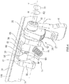
- FIGS. 1 and 2 show a perspective view and a sectional side view of an attached to a slide 100 inventive clamping jaw 10.
- the slide rail 100 has a rectangular cross-section and is encompassed by the clamping claw 10 transverse to the longitudinal axis X of the slide rail 100.
- the slide 100 is contacted by the clamping jaw 10 respectively at its upper rail surface 28, on an operating table, not shown inner rail surface 30, on its lower rail surface 32 and on its outer rail surface 34 and clamped so that the clamping jaw 10 fixed to the Slide rail 100 is attached.
- the clamping claw 10 has an in FIG. 3 separately shown base body 12 with coupling interfaces 13a and 13b for attaching not shown operating table accessories and a generally designated 14 clamping structure, the FIG. 4 is shown in a perspective view with blanking of the base body 12 to the slide rail 100 fitting.
- the clamping structure 14 comprises a support element 20, which forms a first abutment element for engagement with the slide rail 100, a pivot bolt 38, which has a second abutment element for engagement with the slide rail 100 forms, an eccentric shaft 18, an actuating lever 16, a locking mechanism 26 and a helical compression spring 54th
- the support member 20 has an in FIG. 4 shown first leg 56 having a first circular opening 60 and a second leg 58 having a second circular opening 62, through which in each case one connected to the base body 12, in FIG. 4 Not shown bolt is guided.
- the bolts each protrude into a through hole 35 of the main body 12 and have a common longitudinal axis Z, around which the support member 20 is pivotally mounted on the bolt.
- the first leg 56 and the second leg 58 of the support member 20 further each have a third circular opening 61 and a fourth circular opening 63.
- the fourth circular opening is a through hole through the second leg 58 and one connected to the second leg 58 Catch body 25 of the locking mechanism 26 executed.
- the structure of the Rastgesperres 26 will be explained later with reference to FIGS 8 and 9 in more detail.
- the eccentric shaft 18 has a first shaft portion 21, a second shaft portion 22, a third shaft portion 23 and an eccentric 24.
- the shaft portions 21, 22 and 23 are cylindrically shaped and have a common longitudinal axis W between the first shaft portion 21 and the second shaft portion 22nd the cylindrical eccentric 24 is arranged and fixedly connected thereto that the longitudinal axis Y of the eccentric 24 is offset parallel to the longitudinal axis W of the shaft portions 21, 22 and 23.
- the third shaft portion 23 is fixedly connected at one end to the second shaft portion 22 and at the other end to the actuating lever 16.
- first shaft portion 21 is guided through the third opening 61 and the second shaft portion 22 together with the fourth shaft portion 23 through the fourth opening 63 and rotatably supported respectively on the support member 20 about the longitudinal axis W. Due to the rotatable mounting about the longitudinal axis W of the shaft sections 21, 22 and 23, this forms an axis of rotation of the eccentric shaft 18, around which the eccentric shaft 18 in an in FIG. 4 shown first rotational direction R1 and in an opposite second rotational direction R2 is rotatable.
- the eccentric 24 is circular in cross-section, in FIG. 6 shown through hole 59 of the arranged between the legs 56 and 58 of the support member 20 pivot bolt 38 out.
- the pivot bolt 38 is rotatably mounted on the eccentric 24 about its longitudinal axis Y.
- the pivot bolt 38 is substantially L-shaped and has a first leg 39 and a comparatively longer second leg 41.
- first leg 39 engages the slide rail 100 from below.
- second leg 41 Through the upper end of the second leg 41, the eccentric shaft 18 is guided.
- the eccentric shaft 18 has a in FIG. 4 shown pin 40 which is guided through a slot 64 of the pivot bolt 38.
- the pivot bolt 38 has a first stop 66, which passes through the in FIG. 4 lower end of the elongated hole 64 is formed, and a second stop 68, by the in FIG. 3 upper end of the elongated hole 64 is formed, with which the pin 40 can be brought in each case by a rotation of the eccentric shaft 18 about its longitudinal axis Y in a first rotational direction R1 and a second rotational direction R2 opposite thereto.
- the pin 40 is shown in a middle position between the first stop 66 and the second stop 68 in a cross-section of the clamping jaw 10 extending through the pin 40.
- the pivot bolt 38 has a recess and the base body 12 has a recess in which the helical compression spring 54 respectively contacts the pivot bolt 38 and the base body 12.
- the helical compression spring 54 acts on the pivot bolt 38 at its in the Figures 2 and 7 lower side with a spring force and spans it to the slide rail 100 before.
- the pivot latch 38 is in a biased pivotal position relative to the support member 20th
- the eccentric shaft 18 is led out of the detent body 25 and fixedly connected at its end with an actuating lever 16.
- the actuating lever 16 with the eccentric shaft 18 about its axis of rotation W is rotatable.
- an actuating element 27 of the Rastgesperres 26 is attached to the actuating lever 16.
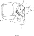
- FIG. 8 shows a perspective view of the clamping claw 10, wherein elements of the Rastgesperres 26 for locking the clamping jaw 10 are visible.
- FIG. 9 a plan view of parts of the clamping claw 10 is shown, which shows the elements of the Rastgesperres 26 in an unlocked state of the clamping structure 14.
- the locking mechanism 26 includes, as already mentioned, the locking body 25 and the actuating element 27 and a first pawl 80 and a second pawl 82, which also in FIG. 5 are shown.
- a saw toothing 78 is formed on the latching body 25.
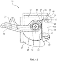
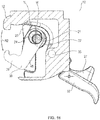
- FIGS. 10 to 16 each show a side view of the clamping jaw 10 in different phases when applying the clamping jaw 10 to the slide rail 100. Furthermore, show the FIGS. 17 to 21 in each case a cross section of the clamping claw 10 from the to FIGS. 10 to 16 opposite perspective in different phases when releasing the clamping claw 10 of the slide rail 100.
- the in the Figures 17 . 18 and 19 The phases shown here each have a similar position of the operating lever as the phases shown in the application in the Figures 16 . 15 and 14 , In the FIGS. 18 to 21 the slide rail 100 is hidden.
- the pivot latch 38 is shown in a receptive position prior to engagement with the slide rail 100.
- helical compression spring 54 is biased so that the first leg 39 of the pivot bolt 38 is in a relation to the horizontal inclined upward pivot position.
- the operating lever 16 is substantially horizontally aligned in the receptive position of the pivoting bolt 38.
- the clamping claw 10 For applying the clamping claw 10 to the slide rail 100, the clamping claw 10 is horizontal in the in FIG. 10 shown alignment on the slide rail 100 moves so that the pivot bolt 38, the outer rail surface 34 contacted. Thereby If the pivoting bolt 38 deviates, ie it is moved counter to the pretensioning force exerted by the helical compression spring 54 about the pivot axis Y (see FIG. FIG. 4 ) pivoted into the base body 12 and thus gives the space for receiving the slide 100 free.
- FIG. 11 shows a side view of the clamping jaw 10 in an open position of the pivot bolt 38 after the clamping jaw 100 has been brought to the slide rail 100.
- the slide rail 100 is contacted in a lower portion 36 of the outer rail surface 34 of the base body 12 and on the lower rail surface 32 of a portion 45 of the pivot bolt 38.
- the operating lever 16 retains its substantially horizontal orientation because the pivoting movement of the pivoting bolt 38 is not transmitted to the operating lever 16.
- this pivotal movement namely the in FIG. 4 shown formed in the pivot bolt 38 slot 64 and arranged therein, formed on the eccentric 24 pin 40 relative to each other, without the pin 40 comes into contact with one of the stops 66, 68 of the slot 64.
- the eccentric shaft 18 fixedly connected to the actuating lever 16 remains unaffected by the pivotal movement of the pivoting bolt 38.
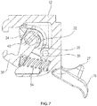
- FIG. 12 In the side view FIG. 12 is the clamping jaw 10 relative to its position in FIG. 11 moves vertically downward so that a convex shaped first abutment surface 46 of the body 12 rests on the upper rail surface 28 and a second abutment surface 48 of the body 12 abuts the inner rail surface 30.
- the first rail edge 29, which is located between the upper rail surface 28 and the inner rail surface 30, is received without contact in an edge recess 42 of the base body 12.
- a contact surface 53 of the support member 20 in the upper region 37 of the outer rail surface 34 is a contact surface 53 of the support member 20, which is arranged in a region remote from the pivot axis Z of the support member 20 (see. FIG. 4 ).
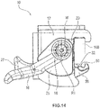
- FIG. 13 shown sectional side view of the voltage applied to the slide rail 100 basic body 12 of the clamping jaw 10, the contact surfaces of the body 12 are illustrated on the slide rail 100.
- the base body 12 has a fourth contact surface 49, which at an in FIG. 13 visible rear side wall 72 is formed and rests against the lower portion 36 of the outer rail surface 34.
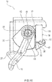
- the operating lever 16 is pivoted downward. With this pivoting movement of the actuating lever 16, the eccentric 24 is pivoted about the axis of rotation W of the eccentric shaft 18 in the first direction of rotation R1.
- the state achieved thereby is in the Figures 14 and 19 shown.
- the pivot bolt 38 is rotated by the pivoting of the eccentric 24 in the first direction of rotation R1 in FIG. 14 moved substantially upward, whereby a convex shaped contact surface 50 of the pivot bolt 38 of the lower rail surface 32 has approximated.
- the pivot bolt 38 is in an intermediate position between the receptive position and a closed position, which in FIG. 16 is shown and explained later.
- the pawls 80 and 82 in this position of the actuating lever 16 with the toothing of the detent body 25 into engagement.
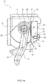
- FIG. 15 is a side view of the applied to the slide 100 clamping jaw 10 is shown in a fixed state.
- the operating lever 16 was relatively to his position in FIG. 14 further pivoted about the axis of rotation W in the first direction of rotation R1 until the eccentric 24 is pivoted so far about the axis of rotation W of the eccentric shaft 18 that the first abutment surface 50 of the pivot bolt 38 abuts against the lower rail surface 32.
- a likewise convexly shaped second contact surface 52 of the pivoting bolt 38 is arranged in this state at a distance from the inner rail surface 30 and thereby secures the clamping claw 10 against detachment from the slide rail 100.
- the pawls 80 and 82 engage with the serration 78 and lock the operating lever 16 against rotation in the second rotational direction R2. As a result, a return movement of the pivot bolt 38 and thus an opening of the clamping claw 10 are prevented.
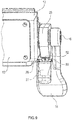
- FIG. 2 shows a side view of the clamping claw 10 applied to the slide rail 100 in the locked state of the clamping structure 14.
- the eccentric 24 by a further pivoting of the actuating lever 16 relative to the position in FIG. 15 further pivoted about the rotation axis W in the first direction of rotation R1, so that the first leg 39 of the pivot bolt 38 is moved so far in the direction of the slide rail 100 that the contact surface 52 of the pivot bolt 38 abuts the inner rail surface 30.
- a second rail edge 31, which is located between the inner rail surface 30 and the lower rail surface 32, is received without contact in an edge recess 44 of the pivot bolt 38. The pivot bolt 38 is thus in the closed position.
- the first pawl 80 and the second pawl 82 engage with the serration 78, whereby the clamping structure 14 is in the locked state, in which the operating lever 16 locks and the clamping jaw 10 securely locks on the slide rail 100 is attached.
- the clamping claw 10 is suitable for attachment to slides with different dimensions.
- the eccentric shaft 18 by a continued pivoting of the actuating lever 16 in the first direction of rotation R1 in abutting the lower rail surface 32 contact surface 50 of the pivot bolt 38 in FIG. 2 moved down and thus the support member 20 is pivoted about the pivot axis Z in the direction of the slide rail 100.
- the closed position of the pivot bolt 38 in FIG. 16 deviating positions can be achieved.
- the pivot latch 38 in the in FIG. 18 shown position in the closed position and the clamping structure 14 in the locked state.
- the clamping claw 10 can be moved vertically upwards until the hook-shaped base body 12 in the in FIG. 11 shown position and the clamping jaw 10 in the in FIG. 11 shown horizontal direction of the slide rail 100 can be moved away.
- the operating lever 16 can again in the relaxed in FIG. 11 penetrateverschwenkt horizontal position in which the pivot bolt 38 again in the in FIG. 10 shown receptive position, in which the pivot bolt 38 is biased by the helical compression spring 54.
- FIG. 22 shown cut side view of the voltage applied to the slide 100 clamping jaw 10 are shown in the locked state of the clamping structure 14 acting on the slide rail 100 forces.
- the base body 12 acts on the slide rail 100 at its upper rail surface 28 with a force FO, at its inner rail surface 30 with a force FI1 and at its outer rail surface 34 with a force FA2.
- the support member 20 urges the outer rail surface 34 with a force FA1 and the pivot latch 38, the lower rail surface 32 with a force FU and the inner rail surface 30 with a force FI2.
- the forces acting on the slide rail 100 forces can be adjusted by pivoting the actuating lever 16 so large that the clamping jaw 10 is fixedly attached to the slide rail 100 by acting between the clamping jaw 10 and the slide rail 100 friction forces.
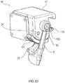
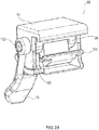
- FIG. 23 a perspective view of a clamping claw 90 is shown according to a second embodiment.
- the clamping claw 90 has a base body 91, which differs from the base body 90 of the first embodiment.
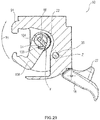
- the first embodiment shown in FIG. 25 separately shown base body 91 on the actuating lever 16 facing side wall 93 has a bore 92 instead of the recess provided in the first embodiment 94.
- the side wall 93 of the base 91 at its in FIG. 3 lower side has a larger recess than the side wall 95 of the first embodiment and has been dispensed with the upper coupling interface 13b.
- the second embodiment has a support member 96, the second leg 98 is formed on its lower side as a latching body 101, as in FIG. 26 is shown.
- the locking body 101 of the support member 96 is in FIG. 23 arranged under the side wall 93 of the main body 91.
- an eccentric shaft 102 is provided which has a relative to the first embodiment staggered pin 104.
- the pin 104 is disposed right next to the second leg 98 and rotated relative to the pin 40 of the first embodiment by 90 ° about the longitudinal axis Y of the eccentric 24.
- a pivot bolt 106 is provided instead of the pivot bolt 38, the slot is offset according to the arrangement of the pin 104 and has a recess 108 instead of the first stop 66. Further, the eccentric shaft 102 does not have a third shaft portion, as in FIG FIG. 27 is shown.
- the second embodiment is easier to install and cheaper to manufacture.
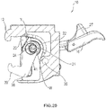
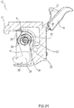
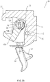
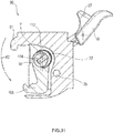
- pivot bolt 106 The different embodiment of the pivot bolt 106 will be described below with reference to the FIGS. 28 to 31 explained, in which the clamping claw 90 is shown in blanking the support member 96 in each case in a cross section through the pin 104 in different positions.
- the pin 104 is at a pivotal movement of the actuating lever 16 relative to the pivot bolt 106 about the longitudinal axis Y of the eccentric 24 in the first direction of rotation R1 in the in FIG. 29 shown pivoted position.
- the pawls 80 and 82 of the actuating lever 16 are in engagement with the first tooth of the toothing of the detent body 101.
- This position of the actuating lever 16 corresponds to the closed position of the pivoting bolt 106 and the locked clamping structure 14 when mounting the clamping claw 90 on a particularly large slide rail.
- the pin 104 is pivoted into the recess 108 of the pivot bolt 106.
- the pivot latch 106 is shown in the closed position resulting from such pivotal movement.
- the pivot bolt 106 is determined by the position of the eccentric 24 in the in FIG. 30 shown position on the slide 100 fixed.
- the pin 104 does not contact the pivot bolt 106, but prevents disengagement of the clamping claw 90 from the slide rail 100 when the clamping claw 90 is pressed against the slide rail 100.
- the pin 104 contacts the pivot bolt 106 on a stop 110, which corresponds to the second stop 68 of the clamping jaw 10 according to the first embodiment, in the open position with corresponding pivoting of the actuating lever 16 about the axis of rotation W in the second rotational direction R2, as in FIG. 31 is shown.
- the structure and function of the chuck 90 correspond to the chuck 10 according to the first embodiment.
Landscapes
- Engineering & Computer Science (AREA)
- General Engineering & Computer Science (AREA)
- Mechanical Engineering (AREA)
- Health & Medical Sciences (AREA)
- Biomedical Technology (AREA)
- Life Sciences & Earth Sciences (AREA)
- Animal Behavior & Ethology (AREA)
- General Health & Medical Sciences (AREA)
- Public Health (AREA)
- Veterinary Medicine (AREA)
- Clamps And Clips (AREA)
- Accommodation For Nursing Or Treatment Tables (AREA)
Priority Applications (1)
| Application Number | Priority Date | Filing Date | Title |
|---|---|---|---|
| PL15781111T PL3215099T3 (pl) | 2014-11-06 | 2015-10-15 | Zacisk do mocowania na szynie ślizgowej stołu operacyjnego |
Applications Claiming Priority (2)
| Application Number | Priority Date | Filing Date | Title |
|---|---|---|---|
| DE102014116169.6A DE102014116169A1 (de) | 2014-11-06 | 2014-11-06 | Spannklaue zur Anbringung an einer Gleitschiene eines Operationstisches |
| PCT/EP2015/073899 WO2016071092A1 (de) | 2014-11-06 | 2015-10-15 | Spannklaue zur anbringung an einer gleitschiene eines operationstisches |
Publications (2)
| Publication Number | Publication Date |
|---|---|
| EP3215099A1 EP3215099A1 (de) | 2017-09-13 |
| EP3215099B1 true EP3215099B1 (de) | 2018-11-21 |
Family
ID=54325556
Family Applications (1)
| Application Number | Title | Priority Date | Filing Date |
|---|---|---|---|
| EP15781111.8A Not-in-force EP3215099B1 (de) | 2014-11-06 | 2015-10-15 | Spannklaue zur anbringung an einer gleitschiene eines operationstisches |
Country Status (10)
| Country | Link |
|---|---|
| US (1) | US20170224569A1 (pt) |
| EP (1) | EP3215099B1 (pt) |
| JP (1) | JP2017533048A (pt) |
| KR (1) | KR20170083576A (pt) |
| CN (1) | CN107106395A (pt) |
| BR (1) | BR112017008887A2 (pt) |
| DE (1) | DE102014116169A1 (pt) |
| PL (1) | PL3215099T3 (pt) |
| RU (1) | RU2017119448A (pt) |
| WO (1) | WO2016071092A1 (pt) |
Families Citing this family (18)
| Publication number | Priority date | Publication date | Assignee | Title |
|---|---|---|---|---|
| DE102013111522B4 (de) * | 2013-10-18 | 2015-05-28 | MAQUET GmbH | Operationstischseitige und vorrichtigungseitige Befestigungseinheit zur Befestigung einer Vorrichtung zum Lagern eines zu röntgenden Patienten an einem Operationstisch und deren Anordnung |
| DE102015101829B4 (de) | 2015-02-09 | 2018-11-08 | MAQUET GmbH | Spannklaue zur Anbringung an einer Gleitschiene eines Operationstisches |
| US9993381B2 (en) * | 2015-05-29 | 2018-06-12 | Innovative Medical Products, Inc. | Knee positioner with expandable carriage |
| EP3357472A1 (en) | 2017-02-07 | 2018-08-08 | Koninklijke Philips N.V. | Sliding accessory rail for holding equipment at a patient support |
| US10952914B1 (en) * | 2017-02-17 | 2021-03-23 | Kyra Medical, Inc | Clamp apparatus for attaching a surgical accessory to a mounting rail |
| US20190159843A1 (en) * | 2017-11-28 | 2019-05-30 | Biosense Webster (Israel) Ltd. | Low profile dual pad magnetic field location system with self tracking |
| CN111002253B (zh) * | 2018-10-08 | 2021-11-02 | 江苏凯普特动力机械有限公司 | 一种便捷型卡合装配定位装置 |
| CN111281725B (zh) * | 2018-12-07 | 2021-10-08 | 上银科技股份有限公司 | 夹持机构 |
| KR102177120B1 (ko) * | 2019-01-02 | 2020-11-11 | 하이윈 테크놀로지스 코포레이션 | 클램핑 기구 |
| BR112021014469A2 (pt) * | 2019-01-22 | 2021-12-28 | Core Arms Llc | Sistema de montagem, dispositivos, métodos e usos dos mesmos |
| US11353159B2 (en) * | 2019-01-22 | 2022-06-07 | Core-Arms, LLC | Mounting system, devices, methods and uses thereof |
| DE102019113097B3 (de) * | 2019-05-17 | 2020-11-12 | Aesculap Ag | Medizinischer Querverbinder mit schwimmender Lagerung und medizinisches Produktset mit dem medizinischen Querverbinder |
| EP3741655B1 (en) * | 2019-05-21 | 2023-07-05 | Thule Sweden AB | A bicycle pannier mounting arrangement |
| TWI689386B (zh) * | 2019-06-27 | 2020-04-01 | 和碩聯合科技股份有限公司 | 夾持裝置 |
| CN110626285B (zh) * | 2019-08-21 | 2021-02-19 | 金华市明辉户外装备有限公司 | 一种suv车锹锁壳结构 |
| US11248634B2 (en) * | 2019-11-27 | 2022-02-15 | GE Precision Healthcare LLC | Clamping device |
| CN111578098A (zh) * | 2020-05-19 | 2020-08-25 | 迈柯唯医疗设备(苏州)有限公司 | 一种通用型快速卡扣机构 |
| US20220273392A1 (en) * | 2021-02-27 | 2022-09-01 | Innovative Medical Products, Inc. | Expandable carriage with adjustable cross nut |
Family Cites Families (19)
| Publication number | Priority date | Publication date | Assignee | Title |
|---|---|---|---|---|
| US4018412A (en) * | 1975-10-14 | 1977-04-19 | Kees Surgical Specialty Company | Bracket for an operating table |
| DE3149215A1 (de) * | 1981-12-11 | 1983-06-30 | Stierlen-Maquet Ag, 7550 Rastatt | Befestigungskloben |
| DE3541638A1 (de) * | 1985-11-26 | 1986-04-30 | Josip 6954 Haßmersheim Siniko | Werkstueckhaltevorrichtung |
| DE9202090U1 (pt) * | 1992-02-19 | 1992-04-16 | Schmitz U. Soehne Gmbh & Co Kg, 5757 Wickede, De | |
| DE4210864A1 (de) * | 1992-04-01 | 1993-10-07 | Siemens Ag | Medizinisches Gerät mit einer Zubehörschiene |
| US5802641A (en) * | 1997-03-07 | 1998-09-08 | Amatech Corporation | Leg holder system for simultaneous positioning in the abduction and lithotomy dimensions |
| US6598275B1 (en) * | 2001-03-12 | 2003-07-29 | Steris, Inc. | Low shadow radiolucent surgical table, clamp systems, and accessories therefore |
| DE10253863B4 (de) * | 2002-11-19 | 2008-07-10 | Maquet Gmbh & Co. Kg | Motorisch verstellbare Kopfstütze |
| US7520007B2 (en) * | 2004-11-10 | 2009-04-21 | Allen Medical Systems, Inc. | Accessory rail clamp with latch and lock mechanisms |
| EP1874255B1 (en) * | 2005-04-11 | 2014-02-26 | Allen Medical Systems, Inc. | Body support apparatus for spinal surgery |
| US9107784B2 (en) * | 2008-09-12 | 2015-08-18 | Carefusion 2200, Inc. | Bedrail clamp |
| US8313070B2 (en) * | 2008-10-31 | 2012-11-20 | Kronner Richard F | Base-clamp assembly |
| DE102009021224A1 (de) * | 2009-05-21 | 2010-11-25 | Aesculap Ag | Halteeinrichtung zur Festlegung von Gegenständen an einer Halteschiene eines Operationstisches |
| CA2902067C (en) * | 2013-01-18 | 2017-12-05 | Alexander Bally | Modular rail adapter system |
| CN103126847A (zh) * | 2013-03-14 | 2013-06-05 | 苏州沃伦韦尔高新技术股份有限公司 | 快拆装夹持器 |
| DE102013108574B4 (de) * | 2013-08-08 | 2017-06-29 | MAQUET GmbH | Spannklauen zur Anbringung an einer Gleitschiene eines Operationstisches |
| DE102013111522B4 (de) * | 2013-10-18 | 2015-05-28 | MAQUET GmbH | Operationstischseitige und vorrichtigungseitige Befestigungseinheit zur Befestigung einer Vorrichtung zum Lagern eines zu röntgenden Patienten an einem Operationstisch und deren Anordnung |
| US20160296401A1 (en) * | 2014-01-22 | 2016-10-13 | Innovative Medical Products, Inc. | Strap clamp assembly |
| DE102015101829B4 (de) * | 2015-02-09 | 2018-11-08 | MAQUET GmbH | Spannklaue zur Anbringung an einer Gleitschiene eines Operationstisches |
-
2014
- 2014-11-06 DE DE102014116169.6A patent/DE102014116169A1/de not_active Ceased
-
2015
- 2015-10-15 BR BR112017008887A patent/BR112017008887A2/pt not_active Application Discontinuation
- 2015-10-15 PL PL15781111T patent/PL3215099T3/pl unknown
- 2015-10-15 EP EP15781111.8A patent/EP3215099B1/de not_active Not-in-force
- 2015-10-15 JP JP2017523988A patent/JP2017533048A/ja active Pending
- 2015-10-15 WO PCT/EP2015/073899 patent/WO2016071092A1/de active Application Filing
- 2015-10-15 RU RU2017119448A patent/RU2017119448A/ru not_active Application Discontinuation
- 2015-10-15 CN CN201580066470.0A patent/CN107106395A/zh active Pending
- 2015-10-15 KR KR1020177015317A patent/KR20170083576A/ko unknown
-
2017
- 2017-04-28 US US15/581,356 patent/US20170224569A1/en not_active Abandoned
Non-Patent Citations (1)
| Title |
|---|
| None * |
Also Published As
| Publication number | Publication date |
|---|---|
| CN107106395A (zh) | 2017-08-29 |
| US20170224569A1 (en) | 2017-08-10 |
| KR20170083576A (ko) | 2017-07-18 |
| WO2016071092A1 (de) | 2016-05-12 |
| RU2017119448A (ru) | 2018-12-06 |
| DE102014116169A1 (de) | 2016-05-12 |
| EP3215099A1 (de) | 2017-09-13 |
| BR112017008887A2 (pt) | 2017-12-19 |
| PL3215099T3 (pl) | 2019-05-31 |
| JP2017533048A (ja) | 2017-11-09 |
Similar Documents
| Publication | Publication Date | Title |
|---|---|---|
| EP3215099B1 (de) | Spannklaue zur anbringung an einer gleitschiene eines operationstisches | |
| DE10147588B4 (de) | Befestigungskloben zur Halterung von Gegenständen an einer Profilschiene | |
| EP3256089B1 (de) | Spannklaue zur anbringung an einer gleitschiene eines operationstisches | |
| EP0918655A1 (de) | Kupplungsanordnung für ein fahrzeug | |
| EP2729324A1 (de) | In seiner längsführung vorverlagerbarer fahrzeugsitz mit klappbarer rückenlehne | |
| DE4426670A1 (de) | Vorrichtung zum Verbinden einer Fensterscheibe mit einem Fensterheber | |
| EP1447573B1 (de) | Befestigungselement | |
| EP0059463B1 (de) | Verbindungsvorrichtung | |
| EP0406652B1 (de) | Kuppelstück zur lösbaren Verbindung von Containern | |
| EP0193081A2 (de) | Türdrückeranordnung | |
| DE10217534A1 (de) | Verriegelungseinrichtung von Einstelleinrichtungen für Lenksäulen von Kraftfahrzeugen | |
| EP2495385B1 (de) | Vorrichtung zum Einsetzen eines Kämpfers in einen Tür- oder Fensterrahmen | |
| DE3604115A1 (de) | Tuerdrueckeranordnung | |
| EP3013634B1 (de) | Verstellvorrichtung mit einem festen element, einem verstellbaren element und einer ersten arretierungsvorrichtung | |
| EP1896219B1 (de) | Verbindungsstelle | |
| DE202016103609U1 (de) | Adapter zur Montage an einem Fixpunkt eines Fahrzeugs | |
| DE19943315B4 (de) | Vorrichtung zum lösbaren Festsetzen eines beweglichen Fahrzeugteils an einem stationären Fahrzeugteil | |
| EP2132848B1 (de) | Vorrichtung zur verankerung eines installationskastens in einer öffnung in einer wandschale | |
| EP2083491B1 (de) | Leitungskanal für elektrische Leitungen | |
| EP3235984B1 (de) | Beschlag für ein fenster, verfahren zum herstellen des beschlags sowie entsprechendes fenster | |
| EP2656943B1 (de) | Anordnung aus Nietbügel und Nietbügelaufnahme mit einer Nietbügelkopplung | |
| EP3860402B1 (de) | Befestigungsvorrichtung zum befestigen einer blende eines schubkastens an einer zarge | |
| EP2514892B1 (de) | System zur Befestigung eines Beschlagteils | |
| DE102014018654A1 (de) | Haltevorrichtung zum Halten einer Sitzanlage an einem Boden eines Fahrzeugs, insbesondere eines Nutzfahrzeugs | |
| DE2248737A1 (de) | Leuchte |
Legal Events
| Date | Code | Title | Description |
|---|---|---|---|
| STAA | Information on the status of an ep patent application or granted ep patent |
Free format text: STATUS: THE INTERNATIONAL PUBLICATION HAS BEEN MADE |
|
| PUAI | Public reference made under article 153(3) epc to a published international application that has entered the european phase |
Free format text: ORIGINAL CODE: 0009012 |
|
| STAA | Information on the status of an ep patent application or granted ep patent |
Free format text: STATUS: REQUEST FOR EXAMINATION WAS MADE |
|
| 17P | Request for examination filed |
Effective date: 20170530 |
|
| AK | Designated contracting states |
Kind code of ref document: A1 Designated state(s): AL AT BE BG CH CY CZ DE DK EE ES FI FR GB GR HR HU IE IS IT LI LT LU LV MC MK MT NL NO PL PT RO RS SE SI SK SM TR |
|
| AX | Request for extension of the european patent |
Extension state: BA ME |
|
| DAV | Request for validation of the european patent (deleted) | ||
| DAX | Request for extension of the european patent (deleted) | ||
| GRAP | Despatch of communication of intention to grant a patent |
Free format text: ORIGINAL CODE: EPIDOSNIGR1 |
|
| STAA | Information on the status of an ep patent application or granted ep patent |
Free format text: STATUS: GRANT OF PATENT IS INTENDED |
|
| INTG | Intention to grant announced |
Effective date: 20180525 |
|
| GRAS | Grant fee paid |
Free format text: ORIGINAL CODE: EPIDOSNIGR3 |
|
| GRAA | (expected) grant |
Free format text: ORIGINAL CODE: 0009210 |
|
| STAA | Information on the status of an ep patent application or granted ep patent |
Free format text: STATUS: THE PATENT HAS BEEN GRANTED |
|
| AK | Designated contracting states |
Kind code of ref document: B1 Designated state(s): AL AT BE BG CH CY CZ DE DK EE ES FI FR GB GR HR HU IE IS IT LI LT LU LV MC MK MT NL NO PL PT RO RS SE SI SK SM TR |
|
| REG | Reference to a national code |
Ref country code: CH Ref legal event code: EP |
|
| REG | Reference to a national code |
Ref country code: IE Ref legal event code: FG4D Free format text: LANGUAGE OF EP DOCUMENT: GERMAN |
|
| REG | Reference to a national code |
Ref country code: DE Ref legal event code: R096 Ref document number: 502015006944 Country of ref document: DE |
|
| REG | Reference to a national code |
Ref country code: AT Ref legal event code: REF Ref document number: 1066685 Country of ref document: AT Kind code of ref document: T Effective date: 20181215 |
|
| REG | Reference to a national code |
Ref country code: CH Ref legal event code: NV Representative=s name: WAGNER + HELBIG PATENTANWAELTE CONSEILS EN PRO, CH |
|
| REG | Reference to a national code |
Ref country code: NL Ref legal event code: MP Effective date: 20181121 |
|
| PG25 | Lapsed in a contracting state [announced via postgrant information from national office to epo] |
Ref country code: IS Free format text: LAPSE BECAUSE OF FAILURE TO SUBMIT A TRANSLATION OF THE DESCRIPTION OR TO PAY THE FEE WITHIN THE PRESCRIBED TIME-LIMIT Effective date: 20190321 Ref country code: ES Free format text: LAPSE BECAUSE OF FAILURE TO SUBMIT A TRANSLATION OF THE DESCRIPTION OR TO PAY THE FEE WITHIN THE PRESCRIBED TIME-LIMIT Effective date: 20181121 Ref country code: LT Free format text: LAPSE BECAUSE OF FAILURE TO SUBMIT A TRANSLATION OF THE DESCRIPTION OR TO PAY THE FEE WITHIN THE PRESCRIBED TIME-LIMIT Effective date: 20181121 Ref country code: BG Free format text: LAPSE BECAUSE OF FAILURE TO SUBMIT A TRANSLATION OF THE DESCRIPTION OR TO PAY THE FEE WITHIN THE PRESCRIBED TIME-LIMIT Effective date: 20190221 Ref country code: HR Free format text: LAPSE BECAUSE OF FAILURE TO SUBMIT A TRANSLATION OF THE DESCRIPTION OR TO PAY THE FEE WITHIN THE PRESCRIBED TIME-LIMIT Effective date: 20181121 Ref country code: LV Free format text: LAPSE BECAUSE OF FAILURE TO SUBMIT A TRANSLATION OF THE DESCRIPTION OR TO PAY THE FEE WITHIN THE PRESCRIBED TIME-LIMIT Effective date: 20181121 Ref country code: NO Free format text: LAPSE BECAUSE OF FAILURE TO SUBMIT A TRANSLATION OF THE DESCRIPTION OR TO PAY THE FEE WITHIN THE PRESCRIBED TIME-LIMIT Effective date: 20190221 Ref country code: FI Free format text: LAPSE BECAUSE OF FAILURE TO SUBMIT A TRANSLATION OF THE DESCRIPTION OR TO PAY THE FEE WITHIN THE PRESCRIBED TIME-LIMIT Effective date: 20181121 |
|
| PG25 | Lapsed in a contracting state [announced via postgrant information from national office to epo] |
Ref country code: AL Free format text: LAPSE BECAUSE OF FAILURE TO SUBMIT A TRANSLATION OF THE DESCRIPTION OR TO PAY THE FEE WITHIN THE PRESCRIBED TIME-LIMIT Effective date: 20181121 Ref country code: PT Free format text: LAPSE BECAUSE OF FAILURE TO SUBMIT A TRANSLATION OF THE DESCRIPTION OR TO PAY THE FEE WITHIN THE PRESCRIBED TIME-LIMIT Effective date: 20190321 Ref country code: SE Free format text: LAPSE BECAUSE OF FAILURE TO SUBMIT A TRANSLATION OF THE DESCRIPTION OR TO PAY THE FEE WITHIN THE PRESCRIBED TIME-LIMIT Effective date: 20181121 Ref country code: RS Free format text: LAPSE BECAUSE OF FAILURE TO SUBMIT A TRANSLATION OF THE DESCRIPTION OR TO PAY THE FEE WITHIN THE PRESCRIBED TIME-LIMIT Effective date: 20181121 Ref country code: GR Free format text: LAPSE BECAUSE OF FAILURE TO SUBMIT A TRANSLATION OF THE DESCRIPTION OR TO PAY THE FEE WITHIN THE PRESCRIBED TIME-LIMIT Effective date: 20190222 Ref country code: NL Free format text: LAPSE BECAUSE OF FAILURE TO SUBMIT A TRANSLATION OF THE DESCRIPTION OR TO PAY THE FEE WITHIN THE PRESCRIBED TIME-LIMIT Effective date: 20181121 |
|
| PG25 | Lapsed in a contracting state [announced via postgrant information from national office to epo] |
Ref country code: DK Free format text: LAPSE BECAUSE OF FAILURE TO SUBMIT A TRANSLATION OF THE DESCRIPTION OR TO PAY THE FEE WITHIN THE PRESCRIBED TIME-LIMIT Effective date: 20181121 |
|
| REG | Reference to a national code |
Ref country code: DE Ref legal event code: R097 Ref document number: 502015006944 Country of ref document: DE |
|
| PG25 | Lapsed in a contracting state [announced via postgrant information from national office to epo] |
Ref country code: EE Free format text: LAPSE BECAUSE OF FAILURE TO SUBMIT A TRANSLATION OF THE DESCRIPTION OR TO PAY THE FEE WITHIN THE PRESCRIBED TIME-LIMIT Effective date: 20181121 Ref country code: SK Free format text: LAPSE BECAUSE OF FAILURE TO SUBMIT A TRANSLATION OF THE DESCRIPTION OR TO PAY THE FEE WITHIN THE PRESCRIBED TIME-LIMIT Effective date: 20181121 Ref country code: RO Free format text: LAPSE BECAUSE OF FAILURE TO SUBMIT A TRANSLATION OF THE DESCRIPTION OR TO PAY THE FEE WITHIN THE PRESCRIBED TIME-LIMIT Effective date: 20181121 Ref country code: SM Free format text: LAPSE BECAUSE OF FAILURE TO SUBMIT A TRANSLATION OF THE DESCRIPTION OR TO PAY THE FEE WITHIN THE PRESCRIBED TIME-LIMIT Effective date: 20181121 |
|
| PLBE | No opposition filed within time limit |
Free format text: ORIGINAL CODE: 0009261 |
|
| STAA | Information on the status of an ep patent application or granted ep patent |
Free format text: STATUS: NO OPPOSITION FILED WITHIN TIME LIMIT |
|
| 26N | No opposition filed |
Effective date: 20190822 |
|
| PG25 | Lapsed in a contracting state [announced via postgrant information from national office to epo] |
Ref country code: SI Free format text: LAPSE BECAUSE OF FAILURE TO SUBMIT A TRANSLATION OF THE DESCRIPTION OR TO PAY THE FEE WITHIN THE PRESCRIBED TIME-LIMIT Effective date: 20181121 |
|
| PG25 | Lapsed in a contracting state [announced via postgrant information from national office to epo] |
Ref country code: TR Free format text: LAPSE BECAUSE OF FAILURE TO SUBMIT A TRANSLATION OF THE DESCRIPTION OR TO PAY THE FEE WITHIN THE PRESCRIBED TIME-LIMIT Effective date: 20181121 |
|
| PG25 | Lapsed in a contracting state [announced via postgrant information from national office to epo] |
Ref country code: MC Free format text: LAPSE BECAUSE OF FAILURE TO SUBMIT A TRANSLATION OF THE DESCRIPTION OR TO PAY THE FEE WITHIN THE PRESCRIBED TIME-LIMIT Effective date: 20181121 |
|
| PG25 | Lapsed in a contracting state [announced via postgrant information from national office to epo] |
Ref country code: LU Free format text: LAPSE BECAUSE OF NON-PAYMENT OF DUE FEES Effective date: 20191015 |
|
| REG | Reference to a national code |
Ref country code: BE Ref legal event code: MM Effective date: 20191031 |
|
| PG25 | Lapsed in a contracting state [announced via postgrant information from national office to epo] |
Ref country code: BE Free format text: LAPSE BECAUSE OF NON-PAYMENT OF DUE FEES Effective date: 20191031 |
|
| PG25 | Lapsed in a contracting state [announced via postgrant information from national office to epo] |
Ref country code: IE Free format text: LAPSE BECAUSE OF NON-PAYMENT OF DUE FEES Effective date: 20191015 |
|
| PGFP | Annual fee paid to national office [announced via postgrant information from national office to epo] |
Ref country code: CZ Payment date: 20200929 Year of fee payment: 6 Ref country code: FR Payment date: 20200923 Year of fee payment: 6 Ref country code: GB Payment date: 20200930 Year of fee payment: 6 |
|
| PGFP | Annual fee paid to national office [announced via postgrant information from national office to epo] |
Ref country code: PL Payment date: 20200922 Year of fee payment: 6 Ref country code: CH Payment date: 20200918 Year of fee payment: 6 |
|
| PGFP | Annual fee paid to national office [announced via postgrant information from national office to epo] |
Ref country code: IT Payment date: 20201019 Year of fee payment: 6 Ref country code: DE Payment date: 20200916 Year of fee payment: 6 |
|
| PG25 | Lapsed in a contracting state [announced via postgrant information from national office to epo] |
Ref country code: CY Free format text: LAPSE BECAUSE OF FAILURE TO SUBMIT A TRANSLATION OF THE DESCRIPTION OR TO PAY THE FEE WITHIN THE PRESCRIBED TIME-LIMIT Effective date: 20181121 |
|
| PG25 | Lapsed in a contracting state [announced via postgrant information from national office to epo] |
Ref country code: HU Free format text: LAPSE BECAUSE OF FAILURE TO SUBMIT A TRANSLATION OF THE DESCRIPTION OR TO PAY THE FEE WITHIN THE PRESCRIBED TIME-LIMIT; INVALID AB INITIO Effective date: 20151015 Ref country code: MT Free format text: LAPSE BECAUSE OF FAILURE TO SUBMIT A TRANSLATION OF THE DESCRIPTION OR TO PAY THE FEE WITHIN THE PRESCRIBED TIME-LIMIT Effective date: 20181121 |
|
| REG | Reference to a national code |
Ref country code: AT Ref legal event code: MM01 Ref document number: 1066685 Country of ref document: AT Kind code of ref document: T Effective date: 20201015 |
|
| PG25 | Lapsed in a contracting state [announced via postgrant information from national office to epo] |
Ref country code: AT Free format text: LAPSE BECAUSE OF NON-PAYMENT OF DUE FEES Effective date: 20201015 |
|
| REG | Reference to a national code |
Ref country code: DE Ref legal event code: R119 Ref document number: 502015006944 Country of ref document: DE |
|
| REG | Reference to a national code |
Ref country code: CH Ref legal event code: PL |
|
| GBPC | Gb: european patent ceased through non-payment of renewal fee |
Effective date: 20211015 |
|
| PG25 | Lapsed in a contracting state [announced via postgrant information from national office to epo] |
Ref country code: MK Free format text: LAPSE BECAUSE OF FAILURE TO SUBMIT A TRANSLATION OF THE DESCRIPTION OR TO PAY THE FEE WITHIN THE PRESCRIBED TIME-LIMIT Effective date: 20181121 |
|
| PG25 | Lapsed in a contracting state [announced via postgrant information from national office to epo] |
Ref country code: GB Free format text: LAPSE BECAUSE OF NON-PAYMENT OF DUE FEES Effective date: 20211015 Ref country code: DE Free format text: LAPSE BECAUSE OF NON-PAYMENT OF DUE FEES Effective date: 20220503 Ref country code: CZ Free format text: LAPSE BECAUSE OF NON-PAYMENT OF DUE FEES Effective date: 20211015 |
|
| PG25 | Lapsed in a contracting state [announced via postgrant information from national office to epo] |
Ref country code: LI Free format text: LAPSE BECAUSE OF NON-PAYMENT OF DUE FEES Effective date: 20211031 Ref country code: CH Free format text: LAPSE BECAUSE OF NON-PAYMENT OF DUE FEES Effective date: 20211031 |
|
| PG25 | Lapsed in a contracting state [announced via postgrant information from national office to epo] |
Ref country code: FR Free format text: LAPSE BECAUSE OF NON-PAYMENT OF DUE FEES Effective date: 20211031 |
|
| PG25 | Lapsed in a contracting state [announced via postgrant information from national office to epo] |
Ref country code: IT Free format text: LAPSE BECAUSE OF NON-PAYMENT OF DUE FEES Effective date: 20211015 |
|
| PG25 | Lapsed in a contracting state [announced via postgrant information from national office to epo] |
Ref country code: PL Free format text: LAPSE BECAUSE OF NON-PAYMENT OF DUE FEES Effective date: 20211015 |
|
| P01 | Opt-out of the competence of the unified patent court (upc) registered |
Effective date: 20230526 |