EP3213788A1 - Ensemble rotor et moteur - Google Patents
Ensemble rotor et moteur Download PDFInfo
- Publication number
- EP3213788A1 EP3213788A1 EP17157168.0A EP17157168A EP3213788A1 EP 3213788 A1 EP3213788 A1 EP 3213788A1 EP 17157168 A EP17157168 A EP 17157168A EP 3213788 A1 EP3213788 A1 EP 3213788A1
- Authority
- EP
- European Patent Office
- Prior art keywords
- impeller
- gases
- partition
- housing
- source according
- Prior art date
- Legal status (The legal status is an assumption and is not a legal conclusion. Google has not performed a legal analysis and makes no representation as to the accuracy of the status listed.)
- Granted
Links
- 239000007789 gas Substances 0.000 claims abstract description 164
- 238000005192 partition Methods 0.000 claims abstract description 63
- 239000000463 material Substances 0.000 claims description 39
- 230000002829 reductive effect Effects 0.000 claims description 17
- 230000007704 transition Effects 0.000 claims description 4
- 238000007789 sealing Methods 0.000 claims description 2
- 230000029058 respiratory gaseous exchange Effects 0.000 description 88
- 230000036316 preload Effects 0.000 description 18
- 238000013016 damping Methods 0.000 description 14
- 210000002105 tongue Anatomy 0.000 description 14
- 230000008901 benefit Effects 0.000 description 11
- 238000004519 manufacturing process Methods 0.000 description 8
- 230000004044 response Effects 0.000 description 7
- 238000004804 winding Methods 0.000 description 7
- 238000010276 construction Methods 0.000 description 6
- 239000012212 insulator Substances 0.000 description 6
- 238000003475 lamination Methods 0.000 description 4
- 229920002379 silicone rubber Polymers 0.000 description 4
- 239000004945 silicone rubber Substances 0.000 description 4
- 230000006870 function Effects 0.000 description 3
- 238000000034 method Methods 0.000 description 3
- 230000008569 process Effects 0.000 description 3
- 230000002441 reversible effect Effects 0.000 description 3
- 239000000758 substrate Substances 0.000 description 3
- 238000005303 weighing Methods 0.000 description 3
- 230000006835 compression Effects 0.000 description 2
- 238000007906 compression Methods 0.000 description 2
- 239000013536 elastomeric material Substances 0.000 description 2
- 239000012530 fluid Substances 0.000 description 2
- 238000002955 isolation Methods 0.000 description 2
- 230000000670 limiting effect Effects 0.000 description 2
- 230000004048 modification Effects 0.000 description 2
- 238000012986 modification Methods 0.000 description 2
- 238000000465 moulding Methods 0.000 description 2
- 239000000615 nonconductor Substances 0.000 description 2
- 208000001797 obstructive sleep apnea Diseases 0.000 description 2
- 239000012858 resilient material Substances 0.000 description 2
- 229920002725 thermoplastic elastomer Polymers 0.000 description 2
- 229920002803 thermoplastic polyurethane Polymers 0.000 description 2
- 150000003673 urethanes Chemical class 0.000 description 2
- XLYOFNOQVPJJNP-UHFFFAOYSA-N water Substances O XLYOFNOQVPJJNP-UHFFFAOYSA-N 0.000 description 2
- YFSLABAYQDPWPF-UHFFFAOYSA-N 1,2,3-trichloro-4-(2,3,5-trichlorophenyl)benzene Chemical compound ClC1=CC(Cl)=C(Cl)C(C=2C(=C(Cl)C(Cl)=CC=2)Cl)=C1 YFSLABAYQDPWPF-UHFFFAOYSA-N 0.000 description 1
- 208000006545 Chronic Obstructive Pulmonary Disease Diseases 0.000 description 1
- 241000237858 Gastropoda Species 0.000 description 1
- 206010041235 Snoring Diseases 0.000 description 1
- 239000006096 absorbing agent Substances 0.000 description 1
- 230000009471 action Effects 0.000 description 1
- 230000009286 beneficial effect Effects 0.000 description 1
- 238000005266 casting Methods 0.000 description 1
- 230000008859 change Effects 0.000 description 1
- 238000004891 communication Methods 0.000 description 1
- 150000001875 compounds Chemical class 0.000 description 1
- 238000009833 condensation Methods 0.000 description 1
- 230000005494 condensation Effects 0.000 description 1
- 239000004035 construction material Substances 0.000 description 1
- 238000011513 continuous positive airway pressure therapy Methods 0.000 description 1
- 238000001816 cooling Methods 0.000 description 1
- 230000008878 coupling Effects 0.000 description 1
- 238000010168 coupling process Methods 0.000 description 1
- 238000005859 coupling reaction Methods 0.000 description 1
- 230000001419 dependent effect Effects 0.000 description 1
- 201000010099 disease Diseases 0.000 description 1
- 208000037265 diseases, disorders, signs and symptoms Diseases 0.000 description 1
- 230000009977 dual effect Effects 0.000 description 1
- 229920001971 elastomer Polymers 0.000 description 1
- 239000006260 foam Substances 0.000 description 1
- 238000010438 heat treatment Methods 0.000 description 1
- 239000003562 lightweight material Substances 0.000 description 1
- 230000013011 mating Effects 0.000 description 1
- 230000007246 mechanism Effects 0.000 description 1
- 239000010445 mica Substances 0.000 description 1
- 229910052618 mica group Inorganic materials 0.000 description 1
- 150000002825 nitriles Chemical class 0.000 description 1
- 229920001296 polysiloxane Polymers 0.000 description 1
- 230000009467 reduction Effects 0.000 description 1
- 230000000241 respiratory effect Effects 0.000 description 1
- 239000005060 rubber Substances 0.000 description 1
- 229920003031 santoprene Polymers 0.000 description 1
- 229920006395 saturated elastomer Polymers 0.000 description 1
- 201000002859 sleep apnea Diseases 0.000 description 1
- 238000000638 solvent extraction Methods 0.000 description 1
- 230000003595 spectral effect Effects 0.000 description 1
- 230000003068 static effect Effects 0.000 description 1
- 230000001225 therapeutic effect Effects 0.000 description 1
- 238000002560 therapeutic procedure Methods 0.000 description 1
- 238000002627 tracheal intubation Methods 0.000 description 1
- 239000003190 viscoelastic substance Substances 0.000 description 1
Images


Classifications
-
- A—HUMAN NECESSITIES
- A61—MEDICAL OR VETERINARY SCIENCE; HYGIENE
- A61M—DEVICES FOR INTRODUCING MEDIA INTO, OR ONTO, THE BODY; DEVICES FOR TRANSDUCING BODY MEDIA OR FOR TAKING MEDIA FROM THE BODY; DEVICES FOR PRODUCING OR ENDING SLEEP OR STUPOR
- A61M16/00—Devices for influencing the respiratory system of patients by gas treatment, e.g. mouth-to-mouth respiration; Tracheal tubes
- A61M16/0057—Pumps therefor
- A61M16/0066—Blowers or centrifugal pumps
-
- A—HUMAN NECESSITIES
- A61—MEDICAL OR VETERINARY SCIENCE; HYGIENE
- A61M—DEVICES FOR INTRODUCING MEDIA INTO, OR ONTO, THE BODY; DEVICES FOR TRANSDUCING BODY MEDIA OR FOR TAKING MEDIA FROM THE BODY; DEVICES FOR PRODUCING OR ENDING SLEEP OR STUPOR
- A61M16/00—Devices for influencing the respiratory system of patients by gas treatment, e.g. mouth-to-mouth respiration; Tracheal tubes
- A61M16/10—Preparation of respiratory gases or vapours
- A61M16/14—Preparation of respiratory gases or vapours by mixing different fluids, one of them being in a liquid phase
- A61M16/16—Devices to humidify the respiration air
-
- F—MECHANICAL ENGINEERING; LIGHTING; HEATING; WEAPONS; BLASTING
- F04—POSITIVE - DISPLACEMENT MACHINES FOR LIQUIDS; PUMPS FOR LIQUIDS OR ELASTIC FLUIDS
- F04D—NON-POSITIVE-DISPLACEMENT PUMPS
- F04D17/00—Radial-flow pumps, e.g. centrifugal pumps; Helico-centrifugal pumps
- F04D17/08—Centrifugal pumps
- F04D17/16—Centrifugal pumps for displacing without appreciable compression
- F04D17/162—Double suction pumps
-
- F—MECHANICAL ENGINEERING; LIGHTING; HEATING; WEAPONS; BLASTING
- F04—POSITIVE - DISPLACEMENT MACHINES FOR LIQUIDS; PUMPS FOR LIQUIDS OR ELASTIC FLUIDS
- F04D—NON-POSITIVE-DISPLACEMENT PUMPS
- F04D25/00—Pumping installations or systems
- F04D25/02—Units comprising pumps and their driving means
- F04D25/06—Units comprising pumps and their driving means the pump being electrically driven
- F04D25/0606—Units comprising pumps and their driving means the pump being electrically driven the electric motor being specially adapted for integration in the pump
-
- F—MECHANICAL ENGINEERING; LIGHTING; HEATING; WEAPONS; BLASTING
- F04—POSITIVE - DISPLACEMENT MACHINES FOR LIQUIDS; PUMPS FOR LIQUIDS OR ELASTIC FLUIDS
- F04D—NON-POSITIVE-DISPLACEMENT PUMPS
- F04D25/00—Pumping installations or systems
- F04D25/02—Units comprising pumps and their driving means
- F04D25/08—Units comprising pumps and their driving means the working fluid being air, e.g. for ventilation
- F04D25/082—Units comprising pumps and their driving means the working fluid being air, e.g. for ventilation the unit having provision for cooling the motor
-
- F—MECHANICAL ENGINEERING; LIGHTING; HEATING; WEAPONS; BLASTING
- F04—POSITIVE - DISPLACEMENT MACHINES FOR LIQUIDS; PUMPS FOR LIQUIDS OR ELASTIC FLUIDS
- F04D—NON-POSITIVE-DISPLACEMENT PUMPS
- F04D29/00—Details, component parts, or accessories
- F04D29/26—Rotors specially for elastic fluids
- F04D29/28—Rotors specially for elastic fluids for centrifugal or helico-centrifugal pumps for radial-flow or helico-centrifugal pumps
- F04D29/281—Rotors specially for elastic fluids for centrifugal or helico-centrifugal pumps for radial-flow or helico-centrifugal pumps for fans or blowers
-
- F—MECHANICAL ENGINEERING; LIGHTING; HEATING; WEAPONS; BLASTING
- F04—POSITIVE - DISPLACEMENT MACHINES FOR LIQUIDS; PUMPS FOR LIQUIDS OR ELASTIC FLUIDS
- F04D—NON-POSITIVE-DISPLACEMENT PUMPS
- F04D29/00—Details, component parts, or accessories
- F04D29/26—Rotors specially for elastic fluids
- F04D29/28—Rotors specially for elastic fluids for centrifugal or helico-centrifugal pumps for radial-flow or helico-centrifugal pumps
- F04D29/30—Vanes
-
- F—MECHANICAL ENGINEERING; LIGHTING; HEATING; WEAPONS; BLASTING
- F04—POSITIVE - DISPLACEMENT MACHINES FOR LIQUIDS; PUMPS FOR LIQUIDS OR ELASTIC FLUIDS
- F04D—NON-POSITIVE-DISPLACEMENT PUMPS
- F04D29/00—Details, component parts, or accessories
- F04D29/40—Casings; Connections of working fluid
- F04D29/42—Casings; Connections of working fluid for radial or helico-centrifugal pumps
- F04D29/4206—Casings; Connections of working fluid for radial or helico-centrifugal pumps especially adapted for elastic fluid pumps
- F04D29/4226—Fan casings
- F04D29/424—Double entry casings
-
- F—MECHANICAL ENGINEERING; LIGHTING; HEATING; WEAPONS; BLASTING
- F04—POSITIVE - DISPLACEMENT MACHINES FOR LIQUIDS; PUMPS FOR LIQUIDS OR ELASTIC FLUIDS
- F04D—NON-POSITIVE-DISPLACEMENT PUMPS
- F04D29/00—Details, component parts, or accessories
- F04D29/58—Cooling; Heating; Diminishing heat transfer
- F04D29/5806—Cooling the drive system
-
- F—MECHANICAL ENGINEERING; LIGHTING; HEATING; WEAPONS; BLASTING
- F04—POSITIVE - DISPLACEMENT MACHINES FOR LIQUIDS; PUMPS FOR LIQUIDS OR ELASTIC FLUIDS
- F04D—NON-POSITIVE-DISPLACEMENT PUMPS
- F04D29/00—Details, component parts, or accessories
- F04D29/66—Combating cavitation, whirls, noise, vibration or the like; Balancing
- F04D29/661—Combating cavitation, whirls, noise, vibration or the like; Balancing especially adapted for elastic fluid pumps
- F04D29/668—Combating cavitation, whirls, noise, vibration or the like; Balancing especially adapted for elastic fluid pumps damping or preventing mechanical vibrations
-
- G—PHYSICS
- G01—MEASURING; TESTING
- G01F—MEASURING VOLUME, VOLUME FLOW, MASS FLOW OR LIQUID LEVEL; METERING BY VOLUME
- G01F1/00—Measuring the volume flow or mass flow of fluid or fluent solid material wherein the fluid passes through a meter in a continuous flow
- G01F1/05—Measuring the volume flow or mass flow of fluid or fluent solid material wherein the fluid passes through a meter in a continuous flow by using mechanical effects
- G01F1/06—Measuring the volume flow or mass flow of fluid or fluent solid material wherein the fluid passes through a meter in a continuous flow by using mechanical effects using rotating vanes with tangential admission
- G01F1/075—Measuring the volume flow or mass flow of fluid or fluent solid material wherein the fluid passes through a meter in a continuous flow by using mechanical effects using rotating vanes with tangential admission with magnetic or electromagnetic coupling to the indicating device
- G01F1/0755—Measuring the volume flow or mass flow of fluid or fluent solid material wherein the fluid passes through a meter in a continuous flow by using mechanical effects using rotating vanes with tangential admission with magnetic or electromagnetic coupling to the indicating device with magnetic coupling only in a mechanical transmission path
-
- A—HUMAN NECESSITIES
- A61—MEDICAL OR VETERINARY SCIENCE; HYGIENE
- A61M—DEVICES FOR INTRODUCING MEDIA INTO, OR ONTO, THE BODY; DEVICES FOR TRANSDUCING BODY MEDIA OR FOR TAKING MEDIA FROM THE BODY; DEVICES FOR PRODUCING OR ENDING SLEEP OR STUPOR
- A61M16/00—Devices for influencing the respiratory system of patients by gas treatment, e.g. mouth-to-mouth respiration; Tracheal tubes
- A61M16/0057—Pumps therefor
- A61M16/0066—Blowers or centrifugal pumps
- A61M16/0069—Blowers or centrifugal pumps the speed thereof being controlled by respiratory parameters, e.g. by inhalation
-
- A—HUMAN NECESSITIES
- A61—MEDICAL OR VETERINARY SCIENCE; HYGIENE
- A61M—DEVICES FOR INTRODUCING MEDIA INTO, OR ONTO, THE BODY; DEVICES FOR TRANSDUCING BODY MEDIA OR FOR TAKING MEDIA FROM THE BODY; DEVICES FOR PRODUCING OR ENDING SLEEP OR STUPOR
- A61M2205/00—General characteristics of the apparatus
- A61M2205/42—Reducing noise
-
- F—MECHANICAL ENGINEERING; LIGHTING; HEATING; WEAPONS; BLASTING
- F04—POSITIVE - DISPLACEMENT MACHINES FOR LIQUIDS; PUMPS FOR LIQUIDS OR ELASTIC FLUIDS
- F04C—ROTARY-PISTON, OR OSCILLATING-PISTON, POSITIVE-DISPLACEMENT MACHINES FOR LIQUIDS; ROTARY-PISTON, OR OSCILLATING-PISTON, POSITIVE-DISPLACEMENT PUMPS
- F04C2270/00—Control; Monitoring or safety arrangements
- F04C2270/04—Force
- F04C2270/041—Controlled or regulated
-
- F—MECHANICAL ENGINEERING; LIGHTING; HEATING; WEAPONS; BLASTING
- F04—POSITIVE - DISPLACEMENT MACHINES FOR LIQUIDS; PUMPS FOR LIQUIDS OR ELASTIC FLUIDS
- F04D—NON-POSITIVE-DISPLACEMENT PUMPS
- F04D27/00—Control, e.g. regulation, of pumps, pumping installations or pumping systems specially adapted for elastic fluids
- F04D27/004—Control, e.g. regulation, of pumps, pumping installations or pumping systems specially adapted for elastic fluids by varying driving speed
-
- Y—GENERAL TAGGING OF NEW TECHNOLOGICAL DEVELOPMENTS; GENERAL TAGGING OF CROSS-SECTIONAL TECHNOLOGIES SPANNING OVER SEVERAL SECTIONS OF THE IPC; TECHNICAL SUBJECTS COVERED BY FORMER USPC CROSS-REFERENCE ART COLLECTIONS [XRACs] AND DIGESTS
- Y02—TECHNOLOGIES OR APPLICATIONS FOR MITIGATION OR ADAPTATION AGAINST CLIMATE CHANGE
- Y02B—CLIMATE CHANGE MITIGATION TECHNOLOGIES RELATED TO BUILDINGS, e.g. HOUSING, HOUSE APPLIANCES OR RELATED END-USER APPLICATIONS
- Y02B30/00—Energy efficient heating, ventilation or air conditioning [HVAC]
- Y02B30/70—Efficient control or regulation technologies, e.g. for control of refrigerant flow, motor or heating
Definitions
- This invention relates to a gases supply and gases humidification apparatus, particularly but not solely for providing respiratory assistance to patients or users who require a supply of gas for the treatment of diseases such as Obstructive Sleep Apnea (OSA), snoring, or Chronic Obstructive Pulmonary Disease (COPD) and the like.
- OSA Obstructive Sleep Apnea
- COPD Chronic Obstructive Pulmonary Disease
- this invention relates to a compressor or blower for use in a gases supply apparatus which in use is integral with the gases supply apparatus.
- Systems for providing therapy of this type have a structure where gases at the required pressure are delivered from a blower (also known as a compressor, an assisted breathing unit, a fan unit, a flow generator or a pressure generator) to a humidifier chamber downstream from the blower. As the gases are passed through the heated, humidified air in the humidifier chamber, they become saturated with water vapour. The gases are then delivered to a user or patient downstream from the humidifier, via a gases conduit.
- a blower also known as a compressor, an assisted breathing unit, a fan unit, a flow generator or a pressure generator
- Humidified gases can be delivered to a user from a modular system that has been assembled from separate units (that is, a system where the humidifier chamber/heater and the breathing unit/blower are separate items) connected in series via conduits.
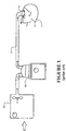
- a schematic view of a user 1 receiving air from a modular assisted breathing unit and humidifier system (together or separately a "breathing assistance apparatus") is shown in Figure 1 .
- Pressurised air is provided from an assisted breathing unit or blower 2a via a connector conduit 10 to a humidifier chamber 4a.
- Humidified, heated and pressurised gases exit the humidifier chamber 4a via a user conduit 3, and are provided to the patient or user 1 via a user interface 5.
- a typical integrated system (“breathing assistance apparatus”) consists of a main blower or assisted breathing unit which provides a pressurised gases flow, and a humidifier unit that mates with or is otherwise rigidly connected to the blower unit. This mating occurs for example by a slide-on or push connection, so that the humidifier is held firmly in place on the main blower unit.
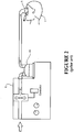
- a schematic view of the user 1 receiving air from an integrated blower/humidifier unit 6 is shown in Figure 2 .
- the system operates in the same manner as the modular system shown in Figure 1 , except that humidifier chamber 4b has been integrated with the blower unit to form the integrated unit 6.
- the user interface 5 shown in Figures 1 and 2 is a nasal mask, covering the nose of the user 1.
- a mask that covers the mouth and nose, a full face mask, a nasal cannula, or any other suitable user interface could be substituted for the nasal mask shown.
- a mouth-only interface or oral mask could also be used.
- the patient or user end of the conduit can be connected to a tracheostomy fitting, or an endotracheal intubation.
- US 7,111,624 includes a detailed description of an integrated system.
- a 'slide-on' water chamber is connected to a blower unit in use.
- a variation of this design is a slide-on or clip-on design where the chamber is enclosed inside a portion of the integrated unit in use.
- An example of this type of design is shown in WO 2004/112873 , which describes a blower, or flow generator 50, and an associated humidifier 150.
- air is drawn by the blower through an inlet into the casing which surrounds and encloses at least the blower portion of the system.
- the blower (controlled by a microcontroller, microprocessor or similar) pressurises the air stream from the flow generator outlet and passes this into the humidifier chamber.
- the air stream is heated and humidified in the humidifier chamber, and exits the humidifier chamber via an outlet.
- a flexible hose or conduit is connected either directly or indirectly to the humidifier outlet, and the heated, humidified gases are passed to a user via the conduit. This is shown schematically in Figure 2 .
- Impeller type fans or blowers are most commonly used in breathing systems of this type.
- An impeller blade unit is contained within an impeller housing.
- the impeller blade unit is connected to a drive of some form by a central spindle.
- a typical impeller housing is shown in Figures 3 and 4 .
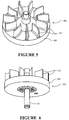
- a typical rotating impeller unit 54, having a plurality of blades 151 and a shroud 152, which in use is located inside the housing is shown in Figures 5 and 6 . Air is drawn into the centre of the impeller unit through an aperture, and is then forced outwards from the centre of the housing towards an exit passage (usually located to one side of the housing) by the blades of the rotating impeller unit.
- domestic users receive treatment for sleep apnea or similar.
- the CPAP device pressure generator provides a flow of gases at a substantially constant pressure.
- the pressure can usually be adjusted before use, or during use, either by a user, or a medical professional who sets up the system.
- Systems that provide variable pressure during use are also known - for example BiPAP machines that provide two levels of pressure: One for inhalation (IPAP) and a lower pressure during the exhalation phase (EPAP).
- Variable pressure or constant pressure systems are all "breathing assistance apparatus"
- the present invention may be said to consist in a breathing assistance apparatus comprising: a pressurised gases source comprising: a gases inlet, a gases outlet adapted to emit pressurised gases to an outlet of the breathing assistance apparatus, and a lightweight impeller.
- a pressurised gases source comprising: a gases inlet, a gases outlet adapted to emit pressurised gases to an outlet of the breathing assistance apparatus, and a lightweight impeller.
- Preferably lightweight impeller is shroudless or otherwise has reduced material.
- Preferably lightweight impeller is formed in one piece.
- the lightweight impeller has a radius of between 15 and 60 mm.
- the lightweight impeller has a mass of less than 2 grams and preferably between 0.8 and 1.8 grams.
- the lightweight impeller has a pressure to inertia to radius ratio greater than 50:1 Pa per gram*mm, and preferably greater than 80:1 Pa per gram*mm.
- the lightweight impeller has a moment of inertia to radius ratio less than 15 g*mm and preferably within the range of 8 to 12 g*mm.
- the lightweight impeller has a blade sweep volume to a blade volume ratio of 16:1 or greater.
- the impeller is a centrifugal impeller rotatable about a central axis.
- the breathing assistance apparatus comprises a motor for driving the impeller wherein the motor is operated using field oriented control.
- the gases source further comprises a housing having upper and lower internal surfaces that enclose the impeller, and wherein the impeller has a plurality of blades that are substantially open to the upper and lower internal surfaces of the housing by virtue of being shroudless.
- the housing forms part of or is integrated with the breathing assistance apparatus.
- the gases source further comprises a partition to define first and second interior regions within the housing, wherein the first and second regions are fluidly connected by an opening formed in or by the partition.
- the opening formed in or by the partition is at least partially circumferential.
- opening formed in or by the partition is crescent shaped.
- the first region is defined by the housing and the partition and comprises the gases inlet.
- the second region is defined by the housing and the partition and comprises the gases outlet.
- the impeller has an axis of rotation, the partition extending radially from the axis of rotation.
- the housing further comprises a volute in the second region.
- the opening is proximate the periphery of the volute.
- the impeller is located within the first region.
- a distal end of the impeller blades curve in the direction of blade rotation.
- the breathing assistance apparatus further comprises a motor, the motor comprising: a rotatable shaft located within a stator, and at least one bearing structure to support the rotatable shaft within the stator, the bearing structure having one or more bearing mounts.
- the bearing mount provides compliant support to the rotatable shaft.
- an outer portion of the one or more bearing mounts engages the stator and/or a stator frame and/or other structure.
- an outer portion of the one or more bearing mounts engages the stator and/or frame of the stator.
- the stator comprises a stator frame, an inner surface of the stator frame engages with the bearing structure.
- the bearing structure further comprises one or more bearings supported by the bearing mounts about the axis of the rotatable shaft.
- the pressurised gases source has a housing and the breathing apparatus further comprises a motor mount that couples the stator and the housing to provide compliant support to the motor.
- bearing mount and/or motor mount are flexible and/or resilient.
- the volute has a tongue at least partially defining a transition between the volute and the gases outlet, the tongue located in the second interior region.
- the bearing mounts have a curved annular body and when engaged with the stator and/or stator frame and/or other structure the annular body is coerced into an engaged configuration that provides preload to the one or more bearings.
- the bearing mount is made from a material that provides resilience and/or flexibility to provide preload when in the engaged configuration.
- bearing mounts are made from a material that provides damping.
- the motor is operated using field oriented control.
- the present invention may be said to consist in a breath assistance apparatus comprising: a motor comprising a rotatable shaft located within a stator, a bearing structure to support the rotatable shaft in the stator, the bearing structure having one or more bearing mounts.
- bearing mounts provide compliant support to the rotatable shaft.
- an outer portion of the one or more bearing mounts engages the stator and/or a stator frame and/or other structure.
- the stator comprises a stator frame, an inner surface of the stator frame engaging with the bearing structure.
- the bearing structure further comprises one or more bearings supported by the bearing mounts about the axis of the rotatable shaft.
- the bearing mount is flexible and/or resilient.
- the bearing mounts have a curved annular body and when engaged with the stator and/or stator frame and/or other structure the annular body is coerced into an engaged configuration that provides preload to the one or more bearings.
- the bearing mount is made from a material that provides resilience and/or flexibility to provide preload when in the engaged configuration.
- bearing mounts are made from a material that provides damping.
- the present invention may be said to consist in a pressurised gases source comprising: a centrifugal impeller driven by a motor within a housing, the housing having a gases inlet, a gases outlet and a partition to define first and second interior regions wherein the first and second regions are fluidly connected by an opening in the partition.
- the first region is defined by the housing and the partition and comprises the gases inlet.
- the second region is defined by the housing and the partition and comprises the gases outlet.
- a breathing assistance apparatus comprising: a pressurised gases source comprising: a housing a gases inlet, a gases outlet adapted to emit pressurised gases to an outlet of the breathing assistance apparatus, a motor with a rotatable shaft and at least one bearing structure to support the rotatable shaft within a stator, the bearing structure having one or more flexible and/or resilient bearing mounts to provide compliance and/or preload and/or damping for the rotatable shaft, a lightweight impeller coupled to the rotatable shaft, a flexible and/or resilient motor mount that couples the stator and the housing to provide compliance and/or damping for the motor a partition to define first and second interior regions within the housing, wherein the first and second regions are fluidly connected by a crescent shaped opening formed in or by the partition.
- the lightweight impeller is shroudless or otherwise has reduced material.
- the lightweight impeller is formed in one piece.
- the lightweight impeller has a radius of between 15 and 60 mm.
- the lightweight impeller has a mass of less than 2 grams and preferably between 0.8 and 1.8 grams.
- the lightweight impeller has a pressure to inertia to radius ratio greater than 50:1 Pa per gram*mm, and preferably greater than 80:1 Pa per gram*mm.
- the lightweight impeller has a moment of inertia to radius ratio less than 15 g*mm and preferably within the range of 8 to 12 g*mm.
- the lightweight impeller has a blade sweep volume to a blade volume ratio of 16:1 or greater.
- the present invention may be said to consist in a pressurised gases source comprising: a gases inlet, a gases outlet, a motor with a shaft, and a lightweight impeller connected to the motor and rotatable to draw gases from the inlet and emit gases through the outlet, wherein the impeller is shroudless or otherwise has reduced material.
- the impeller is a centrifugal impeller rotatable about a central axis.
- the gases source further comprises a housing having upper and lower internal surfaces that enclose the impeller, and wherein the impeller has a plurality of blades that are substantially open to the upper and lower internal surfaces of the housing by virtue of being shroudless.
- the housing forms part of or is integrated with a CPAP machine.
- the gases source further comprises a partition to define first and second interior regions within the housing, wherein the first and second regions are fluidly connected by an opening formed in or by the partition.
- the opening formed in or by the partition is at least partially circumferential.
- the first interior region is defined by the housing and the partition and comprises the gases inlet.
- the second interior region is defined by the housing and the partition and comprises the gases outlet.
- the impeller has an axis of rotation, the partition extending radially from the axis of rotation.
- the housing further comprises a volute in the second region.
- the opening is proximate the periphery of the volute.
- the impeller is located within the first region.
- a distal end of the impeller blades curve in the direction of blade rotation.
- the motor comprising: a rotatable shaft located within a stator, and at least one bearing structure to support the rotatable shaft, the bearing structure having one or more bearing mounts engaged and axially aligned with the stator to provide compliant support to the rotatable shaft.
- an outer portion of the one or more bearing mounts engages the stator.
- the stator comprises a stator frame, an inner surface of the stator frame engaging with the bearing structure.
- the bearing structure further comprises one or more bearings supported by the bearing mounts about the axis of the rotatable shaft.
- the pressurised gases source further comprises a motor mount that couples the stator frame and the housing to provide compliant support to the motor.
- the bearing mount is flexible and/or resilient.
- the volute has a tongue at least partially defining a transition between the volute and the gases outlet, the tongue located in the second interior region.
- the motor is vector controlled.
- the present invention will be described with reference to a breathing assistance apparatus/system where the humidifier chamber is integrated with the gases supply unit (also referred to as a respirator unit or blower unit).
- the gases supply unit also referred to as a respirator unit or blower unit.
- the system is equally applicable to a modular system.
- the present invention relates to a lightweight/low inertia impeller.
- the lightweight nature of the impeller provides low inertia.
- FIG. 7 An example of an integrated gases supply unit 7 with which embodies the present invention is shown in Figure 7 - this is one example and should not be limiting.
- the integrated unit 7 comprises two main parts: a gases supply unit or blower unit 8 and a humidifier unit 9.
- Humidification unit 9 is partially enclosed within the external shell 80 of the blower unit 8 in use, except for the top of the humidification unit 9.
- It also comprises an internal controller 14 such as a microcontroller, microprocessor or similar for controlling the blower unit and other operations, such as that shown schematically in dotted lines. It is not necessary to describe the structure and operation of the humidification unit 9 in detail in order to fully describe the present invention.
- the body of the gases supply unit 8 has the form of a generally rectangular block with substantially vertical side and rear walls, and a front face that is angled slightly rearwards (all the walls can be angled inwards slightly if required).
- the walls, base and top surface are all manufactured and connected as far as possible to minimise the occurrence of seams, and any necessary seams are sealed.
- the gases supply unit 8 includes a control knob 11, located on the lower section of the front face of the gases supply unit 8, with a control display 12 located directly above the knob 11.
- a patient outlet 30 is shown passing out of the rear wall of the gases supply unit 8. In the preferred embodiment, the free end of the outlet 30 faces upwards for ease of connection.
- the patient outlet 30 is adapted to allow both pneumatic and electrical connection to one end of a conduit - e.g. conduit 3 - running between the integrated unit 7 and a patient interface - e.g. interface 5.
- a conduit - e.g. conduit 3 - running between the integrated unit 7 and a patient interface - e.g. interface 5.
- An example of the type of connector that can be used and the type of dual connection that can be made is described in US 6,953,354 . It should be noted that for the purposes of reading this specification, the patient interface can be thought of as including both the interface 5 and the conduit 3 where it would be appropriate to read it in this manner.
- the gases supply unit 8 includes an enclosing external shell 80 which forms part of, and encloses, the gases supply unit 8.
- the shell 80 includes internal air passages for ducting air passing through the gases supply unit 8, and also internal recesses, cavities or slots into which components of the gases supply unit 8 is located in use.
- the shell 80 of the gases supply unit 8 is further adapted to include an open-topped compartment 13.
- humidifier chamber 9 is located within the compartment 13.
- Blower unit 8 includes a heater base or heater plate, located at the bottom of the compartment 13.
- a humidifier inlet aperture 15 and humidifier outlet aperture 16 are located on the wall of the compartment 13, towards the top of the compartment 13.
- the inlet and outlet apertures 15, 16 are aligned so as to mate with inlet and outlet humidifier ports 17, 18 located on the humidifier chamber 9, when the system is in use.
- humidifier inlet is possible.
- the humidifier inlet aperture 15 will not be connected directly to the humidifier chamber, but will be connected instead to one end of a conduit or similar leading from the humidifier inlet aperture on the gases supply unit, to the humidifier chamber.
- Air from atmosphere is drawn into the shell of the gases supply unit 8 through an atmospheric inlet vent 19.
- This vent 19 can be located wherever is convenient on the external surface of the shell of the gases supply unit 8.
- the inlet vent 19 is located on the rear face of the shell of the gases supply unit 8, on the right hand side of the rear face (right hand side when looking forwards).
- air is drawn in through the inlet vent 19 by means of a fan unit 20 which forms part of the gases supply unit 8, and which is located inside the enclosing external shell of the gases supply unit 8.
- the fan unit 20 provides a pressurised gases stream for the gases supply unit and therefore the assisted breathing system.
- the fan unit 20 will be described in more detail below.
- Path C runs from the inlet vent 19 up over the power supply cavity and though the venturi (shown in dotted lines) past into curved path 22 (including absorber foam channel and through a thermistor flow sensor) to an aperture 23 formed in the gases supply unit shell 80, the aperture 23 passing into a recess/plenum 21 which is formed in the gases supply unit shell 80, in which the fan unit 20 is located. The air then passes into the inlet 27.
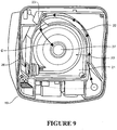
- the shell of the gases supply unit 8 includes a chamber or outlet duct 26 which forms at least part of an outlet air path to allow gaseous communication between the fan unit 20 and the humidifier inlet aperture 15.
- the outlet duct 26 runs up between the right hand side wall of the gases supply unit 8 (from behind looking forwards) and the front wall, up to the humidifier inlet aperture 15. As shown in Figures 9 and 10 , air exiting the fan unit 20 enters the duct 26.
- the humidifier inlet aperture 15 forms an outlet at the end of the duct 26.
- the gases are humidified and heated in the chamber 9, before passing out of the chamber 9 through the humidifier outlet aperture 16, which is directly or indirectly connected to the patient outlet 30 (it should be noted that the outlet of the humidifier chamber 9 could also be completely separate from the gases supply unit 8).
- the heated humidified gas is then passed to the user 1 via conduit 3.
- the patient outlet 30 is adapted to enable pneumatic attachment of the patient conduit 3, and in the preferred embodiment, outlet 30 is also adapted to enable electrical connection via an electrical connector.
- a combined electrical and pneumatic connection can be useful for example if the conduit 3 is to be heated. Electrical heating of a conduit such as conduit 3 can prevent or minimise the occurrence of condensation within the conduit 3. It should also be noted that the outlet connection does not have to be via the shell of the integrated unit 7. If required, the connection for the conduit 3 could be located directly on an outlet from humidifier chamber 9.
- the blower unit 8 in use is set to a user-specified pressure level and/or the pressure level can be automatically controlled.
- the flow rate for the preferred embodiment will vary during use, depending on the users breathing.
- the power to fan unit 20 can be altered, to change the speed at which the impeller 24 is rotating, and therefore the pressure.
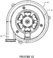
- the structure of the fan unit 20 shall now be described, with particular reference to Figures 11 , 12 and 13 .
- the fan unit 20 is located in recess 21 of the shell of the gases supply unit 8 in use, as described above with reference to Figures 9 and 10 .
- the fan unit 20 comprises a rotating impeller located inside a casing having the form of a snail or scroll casing 25.
- the fan unit 20 appears generally circular in plan view, as shown in Figures 11 and 12 .
- the fan casing 25 includes an inlet aperture 27.
- inlet aperture 27 is a circular hole located in approximately the centre of the casing 25 and passing from the outside of the casing to the inside. Air from the inlet path 22 (see Figure 10 ) enters the fan casing 25 via the inlet aperture 27. It should be noted that where it would be appropriate to include the aperture 23 and at least part of the recess 21 as part of the air inlet path, the specification should be read as including these elements.
- the preferred form of the casing 25 of the fan unit 20 also includes an outlet passage 28.
- the outlet passage 28 is a short passage formed as an integral part of the casing 25 and aligned substantially tangentially to the circumference to the remainder of the generally circular casing 25.
- a fan casing outlet aperture or exit aperture 29 (see e.g. Figure 13 ) is located at the outer end of the passage 28. It should be noted that the fan casing exit aperture 29 could be located wherever is convenient on the passage 28 (i.e. it does not have to be at the end of the passage, it could be through the passage wall partway along its length, for example). Exit aperture 29 opens into the duct 26.
- the outlet passage 28 forms part of the air path from the fan to the humidifier inlet aperture 15.
- the fan casing 25 encloses the fan in use, except for the inlet aperture 27 and the exit aperture 29 of the passage 28.
- rotation of the fan unit 20 is driven by a motor, the fan or impeller unit being adapted for connection to the motor. Air or gases are drawn through inlet aperture 27 in the centre of the casing 25, into the centre of the impeller unit 24, and are then forced outwards as a gases stream through the exit aperture 29 of the outlet passage 28 by the impeller blades 31 as the impeller unit 24 rotates.
- the fan outlet passage or exit passage 28 has a generally rectangular cross-section, and the exit passage 28 is aligned substantially tangentially to the casing 25.
- the cross-section of the fan outlet passage 28 could be any suitable shape, such as oval, rectangular or circular.
- the fan outlet passage 28 could also be arranged at any suitable angle to the impeller unit, for example facing radially outwards, or at any suitable angle between tangential and radial.
- the fan outlet passage 28 causes the gases forced outwards by the impeller unit 24 to coalesce as a fluidic gases stream, and dictates the direction in which the gases stream flows. The overall path or overall direction of the gases flow will be along the passage from the fan towards the fan casing exit aperture 29.
- the impeller 24 has a plurality of blades 31 extending outward from a central hub 32.
- the impeller is a centrifugal impeller.
- the hub 32 defines the axis about which the impeller rotates.
- the hub 32 has an aperture or recess on the underside to allow engagement with a motor shaft which facilitates impeller rotation.
- other engagement mechanisms such as over moulding of the hub with a shaft, could be used.
- the impeller is preferably made in one piece ("one piece construction"), as opposed to moulded in multiple parts and joined. This is possible when there is no shroud - or at most one shroud. This reduces misalignment of components that might lead to imbalance or other disadvantages. In the preferred embodiment there is no shroud (in contrast with for example the shroud 152 shown in Figures 5 and 6 .)
- the blades 31 preferably provide a substantially flat surface, from the hub 32 to the blade tip, and incident the direction of rotation to thereby centrifuge gases.
- the tips of the impeller blade tips 33 partially curve in the direction of impeller rotation ("arrow "A"). That is, the blade tips 33 are forward swept. Forward swept blade tips help to impart stronger rotational forces on the gases flowing through the impeller than straight or backswept blades. The forward swept blade tips help to produce a high pressure annulus between beyond tip of each blade.
- the inner portion 31 of the impeller blade may be somewhat backswept. A backswept blade allows for some recirculation of gases on the blade surface itself. The backswept inner blade portion may be beneficial to increase pressure generation and allow for stable low and reverse gases flow.
- the impeller is constructed to be lightweight. Preferably, this is by making the impeller shroudless, or at least partially shroudless, thereby removing weight.
- each of the blades 31 of the preferred impeller 24 are open between the blades (that is, the upper and lower "faces” or “planes” of the impeller are open to the internal surfaces of the housing of the fan unit 20) thereby defining a shroudless centrifugal impeller.
- the weight of the impeller 24 can be substantially reduced.
- the weight of the impeller can also be reduced in other ways, in addition to or alternatively to omitting the shroud.
- a lightweight material can be used.
- thin blades with minimal material and large gaps between blades could be implemented to reduce weight.
- a shroud 35 with some of the material removed, such as shown in Figures 14b, 15b could be used.
- a scalloped shaped 36 shroud is provided whereby some of the material between blades 31 is removed. Any suitable amount of material could be removed.
- a shroud channels air from the impellers. Where significant material is removed, the resulting structure may in fact no longer carry out this function of a shroud but rather just provide support for impeller blades 31.
- the impeller 24 may still be considered shroudless, despite having some structure between impeller blades 31.
- the structure between the impeller blades is a webbing that is disposed centrally between impellers. Such as structure does not function as a shroud.
- the reduced material structure or webbing 36 can be of any shape (not just scalloped) or extent, of which Figures 14b, 15b , 14c, 15c show two examples.
- a lightweight impeller 24 provides benefits such as manufacturing cost, low rotational inertia and is balanced or requires little effort to rotationally balance once manufactured. An impeller with low rotational inertia can be quickly accelerated and decelerated.
- a lightweight, shroudless impeller is therefore suited for quickly responding to fluctuating pressure requirements, such as the normal inhalation and exhalation cycle of a patient connected to the breathing assistance device in which the impeller operates.
- a conventional shrouded impeller commonly used on a breathing assistance device can respond to pressure fluctuations of 10 cmH2O in approximately 2 seconds.
- the preferred impeller weighing approximately 1.7 grams and inertia of 0.5 kg.mm2 responds pressure fluctuations of 10cmH2O in approximately 100ms.
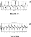
- Figure 29A shows a graph of pressure verses time for the earlier impeller weighing 17 grams. The impeller is operated to attempt to maintain a constant pressure of 4cmH2O during the normal inhalation and exhalation cycle of a patient.
- Figure 29B shows a graph of pressure verses time for the preferred impeller 24.
- the lightweight can be achieved by omitting a shroud. However, it is not necessary to omit the entire shroud - rather just sufficient shroud to bring the weight of the impeller to a suitable level - such as shown in Figures 14B, 15B , 14C, 15C . Therefore, lightweight can be achieved by having as much open space (area or volume) between the blades as possible.
- the open space can be defined in terms of the blade volume to blade sweep volume ratio/percentage. That is, the blades sweep a volume X when rotating and the blades themselves have a combined volume Y (which is the volume of each blade combined). Alternatively, from a plan perspective, the open space can be defined in terms of the blade area to the blade sweep area.
- the ratios should be kept as low as possible.
- the swept volume of the impeller is approximately 19,000mm3, where the blades constitute a volume of approximately 1,200mm3.
- the ratio of swept volume to blade volume is therefore approximately 16:1, thereby defining an impeller that is lightweight compared to the smaller, more densely designed and heavier impellers used earlier.
- the lightweight impeller can have a weight for example of less than 2 grams and preferably between 0.8 and 1.8 grams, or more preferably, between 1.2 and 1.7 grams, or even more preferably 1.7 grams. These are just examples or a preferred embodiment and the impeller need not be this weight, but some other weight that renders it lightweight.
- a lightweight impeller can be designed to remove as much of the shroud as necessary to bring the moment of inertia to radius ratio down to preferably less than 15 gram*mm, and more preferably between 8-12 gram*mm and in one possible embodiment approximately 11 gram*mm.
- such an impeller can have a radius of 35mm, a circumference of 219 mm, and at 15,000 rpm a moment of inertia of 344.22, a tip speed of 54.98 m/s, a pressure of 1,800 Pa and a tip speed to inertia to radius ratio of 3.5 or more and for example 5.59.
- a lightweight impeller could have dimensions/parameters within the following ranges (note these ranges are indicative - not limiting):
- Lightweight impellers enable larger radius impellers to be used. Yet larger radius impellers can be used than those mentioned above. Larger radius impellers provide greater tip speed and pressure.
- the construction of the impeller allows for greater radius impellers because the lightweight nature of the impeller is such that even with larger impellers, the inertia is still low enough to provide the required response and pressures.
- the lightweight nature of the impeller can be achieved through removing mass through any suitable means, such as removing the shroud and/or material from the impeller and/or using lighter materials.
- One possible manner in which to reduce impeller mass is to reduce the number of blades.
- the impeller generates a high pressure annulus between the tip and inner face of the housing.
- the backward facing impeller with a forward sweep at the tip also allows for recirculation on the blade itself, which helps with increased pressure generation and stable flow and reverse flows.
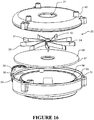
- the fan unit 20 as shown in Figures 11 and 12 and described above is shown in exploded form in Figure 16 .
- the blower has an upper housing layer 50 and a lower housing layer 51 that assemble to encapsulate a partitioning layer 52 and the impeller 24.
- the blades of the impeller are open to the internal surfaces of the upper and lower housing layers.
- the partition layer 52 and the inner surface of the upper layer 50 are profiled to substantially enclose the impeller blades when the layers are assembled. This forms a first interior region ("upper region").
- the upper housing layer 50 has the aperture 27 that defines the gases entry into the blower.
- the lower housing layer defines a volute 53 where gases are collected before emission from the blower.
- the volute 53 also has a sealing inner wall 56.
- the wall 56 defines a space internal to the lower housing that may be used to house a motor.
- the lower housing layer 51 and the partition 52 form a second interior region ("lower region").
- the outlet passage 28 of the fan unit 20 is connected to the volute 53 via an aperture 54.
- the aperture 54 and the volute wall 53 define a tongue 55 whereby gases circulating in the volute 53 are diverged into the outlet passage 28.
- the partition layer 52 is generally circular and substantially divides the upper housing 50 from the lower housing 51 thereby defining the upper and lower gases flow (interior) regions of the blower.
- an aperture (opening) 57 is located at, or close to the outer edge of the partition.
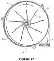
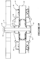
- the aperture 57 is shown more clearly in Figures 17 and 18 .
- the aperture 57 is most preferably an opening formed by a cut-away in the partition layer 52, or some other configuration/shape of the housing 51 such that the combination/arrangement of the partition layer 52 and the housing 51 creates an aperture/opening between the two.
- the aperture 57 may also comprise a flow path formed separately to the partition layer, such as a bulge or fluid channel formed in the walls of the upper 50 and lower housings 51.
- the cut-away could form a circumferential aperture 57 between the housing 51 and partition 52, for example.
- the curvature/centre of radius of the circumferential aperture 57 is preferable offset from the centre of radius of the partition 52 or otherwise has a curvature that differs from that of the circumference of the partition 52 resulting in an eccentric or otherwise offset circumferential aperture 57 around the circumference of the partition 52 as shown in the Figures. This produces an aperture 57 with a crescent ("smile") shaped opening that spans a leading edge 58 to a trailing edge 59.
- the aperture may be of any shape with a gradual opening and closing relative to the plane of impeller rotation.
- the aperture allows for gradual supply of pressure and flow from the high static pressure source at the top of the blower.
- the angle of the aperture opening and closing is tuned to allow for reverse flow to return through the system in a stable fashion. It also contributes to the blade pass noise reduction by not having a sharp break in geometry.
- the aperture provides addition tongues, as well as that on the outlet.
- the gradual opening and closing of the aperture (“tapers”) provides tongues.
- the maximum velocity at the outlet e.g. 10m/s
- the gradual opening and closing with blades passing at that speed manages blade pass noise.
- the width and length of the aperture 57 controls the velocity in the lower (volute) section of the housing. A wider and longer aperture increases velocity in the volute, for example.
- the impeller 24 is rotated in direction A - see Figure 17 .
- the rotation of the impeller 24 draws gases through the inlet 27 and through the blades 31 toward the outer wall of the upper housing layer 50.
- air B can also be drawn through the stator/rotor from the other side of the housing - see e.g. Figure 13 .
- the air B drawn through can cool the motor.
- the shroudless impeller 24 enables air to be drawn through the motor in this manner thus providing cooling.
- the forward swept blade tips 31 impart strong rotational forces to the gases circulating in the upper region of the blower housing to thereby create high circulating gas speeds. Gases in the upper region will naturally flow through the aperture 57 to the lower region due to pressure differential between regions.
- the gases in the upper region having a high velocity and low pressure, enter the lower region, specifically the volute 53, the gas velocity drops and the pressure increases.
- the volute 53 has a greater volume than the upper region to help facilitate a gases pressure increase.
- blower internal space By dividing the blower internal space into two separate regions a number of advantages can be realised.
- high velocity gases leaving the impeller are incident to the edge, or tongue, that defines a physical boundary where gases are split from the volute to enter the outlet passage.
- High velocity gas flow at incident the tongue is turbulent and inefficient to blower performance.
- the turbulence caused by the tongue reduces also introduces a source of noise.
- dividing the housing of the preferred blower into the upper and lower regions reduces the impact caused by the tongue.
- the upper region allows the gases to circulate at a high speed.
- the gradual radial opening and closing of the preferred partition 57 provides a fluid path to the lower region that is free from (or has reduced) aerodynamically turbulent edges.
- the blower unit When circulating gases have entered the lower region, the enlarged volume of the volute encourages the gases to slow and increase pressure.
- the reduced gases velocity reduces the impact of turbulence normally caused by the tongue 55 to a low or negligible level.
- the blower unit is therefore able to operate across a wide pressure and flow range with substantially reduced noise output when compared to other blowers.
- a wider and longer aperture 57 increases the flow rate of the lower region relative to the upper region. Therefore, the size of the aperture is selected according to the desired flow rate and pressure range of the blower unit.
- the motor used to drive the impeller 24 is shown in cross section in Figure 19 .
- the motor is a brushless DC motor operated using sensorless vector control (also termed "field oriented control") controlled by a microcontroller, microprocessor or similar controller 14 (such as shown in Figure 7 ), for example, via the connector 131 mounted to a PCB 130.
- the control can be tuned to suit a low inertia impeller.
- the central hub 32 of the impeller 31 is engaged with a shaft 60 that extends from the motor 61.
- Mounted to the shaft is a plurality of, preferably small, magnetic segments to form a rotor 62.
- the magnet is 20mm in diameter, but more generally the diameter could be less than 20mm and preferably between 10mm to 15mm.
- the magnet volume is less than 1600mm3 and can be between 500mm3 and 1600mm3.
- Surrounding the rotor 62 is a laminated stator having a plurality of poles 63 and windings 68.
- the stator is mounted to the PCB or other substrate 130 and the windings coupled to the connector 131.
- the windings are selectively energised by the microcontroller 14 via the connector 131 to facilitate rotation of the rotor, and therefore the shaft 60 and impeller 31, about the central axis defined by the centreline of the shaft 60.
- the shaft 60 is held within the motor by a bearing structure.
- the bearing structure has one or more bearings 64 and one or more bearing mounts 65.
- the bearing mounts 65 as shown engage with the bearings on an inner surface and with the stator on an outer surface.
- the preferred engagement of the mount to the bearings and the stator is frictional.
- the bearing mounts 65 are made of a soft, yet resilient and/or flexible material such as silicone rubber or other elastomeric material. The material can be low creep, temperature stable, low compression set with a high tan delta (highly viscous), highly damped. Examples comprise:
- mounts 65 Such materials allow the mounts 65 to compress when installed, then expand into their chosen location to be held in place by engagement expanded dimension with a restriction.
- the mounts 65 are optionally restrained by an overhang 66 formed as part of an electrical insulator/isolator or other frame structure ("stator frame") on the stator.
- the bearings may be restrained by an overhang 67 formed as part of the bearing mount. Either or both of the overhangs may be discretely positioned about the inner and outer annulus of the bearing mounts, or alternatively, extends around the circumference of the mount to define a recess in which the mount is located.
- the bearing mounts provide compliance to the rotatable shaft 60.
- rotatable objects such as the rotor 62, shaft 60 and impeller 31 usually suffer from some degree of rotational imbalance
- the bearing mounts are able to isolate inherent rotation induced vibration from the motor rotor.
- combination of the lightweight, shroudless impeller having a low rotational inertia, as described above, together with the given compliance of the bearing mounts enables the rotor 62, shaft 60 and impeller 31 to be manufactured and any post manufacture balancing process for the rotating components entirely omitted.
- the lightweight nature of the impeller allows any imbalances to be compensated by the bearing mounts.
- a lightweight impeller also allows faster speed response of the impeller to changing conditions. Any unwanted fluctuations in pressure due the lack of shroud can be compensated for by quickly changing the impeller speed to return pressure to the desired level.
- Figure 19 shows the bearing mounts 65 mounted within the motor stator, they may equally be housed externally to the motor.
- the mounts 65 may instead be mounted within journals formed within the blower housings, or the gases supply unit 7.
- the motor and impeller can optionally be mounted on a compliant mounting device.
- Figure 20 shows one embodiment of such a mounting device 70.
- the mount is most preferably made from a soft, flexible yet resilient material such as silicone rubber.
- the mounting device 70 has an internal recess 71 in which the stator is relieved.
- the internal recess is smaller than the outer surface of the motor to encourage an interference fit between these components.
- Figure 21 shows the motor 61 positioned within the mounting recess 71.
- a plurality of projections 72 encircles the upper and lower surfaces of the mount 70.
- Each projection 72 preferably has a base recessed into the body of the mount to effectively increase the length whereby the projections are free to bend.
- the end of projection extends past the upper and lower surfaces of the mount to provide supporting leverage to the mount and motor assembly.
- vibration caused by any imbalance of the rotational components is absorbed by each of the projections by allowing the body of the mount 70 to move relative to the surface on which the projections 72 are supported.
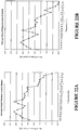
- Figure 22A is a graph of the sound pressure level of a conventional fan unit tested in an anechoic chamber.
- Figure 22B is a graph of the sound pressure lever of a fan unit according to the present invention. It can be seen that the lightweight and shroudless impeller 24, the flexible bearing mounts 65 and flexible motor mount 70 contribute to a significantly reduced noise output across the tested spectral range of 50Hz to 10kHz.
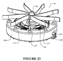
- FIG. 23 A further embodiment of the motor and impeller assembly is shown in Figures 23 to 28 .
- Many aspects of this embodiment are the same as those in the previous embodiment. Features described in relation to the previous embodiment not described in this embodiment can be assumed to exist in this embodiment where appropriate. Like features will use the same reference numerals as the previous embodiment.
- the motor used to drive the impeller 24 is shown in cross-section in Figure 27 .
- the motor is a brushless DC motor operated using sensorless vector control ("field oriented control") controlled by a microcontroller, microprocessor or similar controller 14 (such as shown in Figure 7 ), for example, via a connector 231 mounted to a PCB/substrate 230 (such as shown in Figure 23 ).
- the control can be tuned to suit a low inertia impeller.
- the central hub 32 of the impeller 24 is engaged with a shaft 60 that extends from the motor 61.
- a shaft 60 that extends from the motor 61.
- a plurality of, preferably small, magnetic segments to form a rotor 62.
- a laminated stator 241 Surrounding the rotor 62 is a laminated stator 241 having an annular outer portion 242 and a plurality of poles 243 and windings 68.
- the stator is mounted to the PCB or other substrate 230 and the windings 68 coupled to the connector 231.
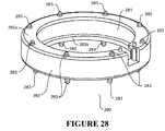
- the stator 241 has an electrical insulator/isolator (forming a stator frame) 270a, 270b covering the top and bottom of the annular portion 242 and the poles 243.
- Each winding 68 is preferably assembled on the insulator 270a, 270b over each pole 243. Protrusions for engagement and retainment are provided around the circumference 271 extending upwards and at the end of the poles extending upwards 272a and downwards 272b.
- each lamination comprises a annular outer portion 242 and a pole portion 243 extending radially inwards.
- the edge 244 of each pole portion 243 includes a wave shape.
- the wave shape comprises two concave portions 244a, 244b meeting at a central apex 244c.
- each pole 243 has an inner radial face 250 with a wave shape as shown in Figure 25 .
- the face 250 comprises two concave portions 250a, 250b meeting at a central apex 250c. This arrangement reduces cogging.
- the stator and/or rotor can have a skewed magentisation.
- the windings are selectively energised using the controller 14 via the connector 231 to facilitate rotation of the rotor, and therefore the shaft 60 and impeller 31, about the central axis defined by the centreline of the shaft 60.
- the shaft 60 is held within the motor by a bearing structure.
- the bearing structure has one or more bearings 64 and one or more bearing mounts 260 (see Figure 26 ).
- the bearing mounts 260 as shown engage with the bearings 64 on an inner surface 261 and with the stator 241/insulator 270a/270b on an outer surface as shown in Figure 27 .
- the bearing mount 260 comprises a main annular body 265 that curves from a low point at a central aperture 263 to a higher point at the outer circumference 262.
- the outer circumference comprises an engaging lip 264, preferably with a chamfer 264a on the intersection of the outer circumference 262 with the main annular body 265.
- the intersection of the inner aperture 263 with the inner circumference 261 of the main body 265 also preferably has a chamfer 261a.
- An annular wall/boss 266 extends upwardly from the main annular body 265 at the inner aperture 263.
- the top portion 267 of the annular wall 266 has an overhanging engagement lip 268.
- the intersection of the lip 268 with the annular wall 266 and with the overhanging lip side wall 268a are preferably chamfered 268b, 268c.
- the preferred engagement of the bearing mount 260 to the bearings 64 and the stator 241 is frictional.
- the bearing mounts 260 are made of a soft, yet resilient and/or flexible material such as silicone rubber or other elastomeric material.
- the material can be low creep, temperature stable, low compression set with a high tan delta (highly viscous), highly damped. Possible materials were describe in relation to the previous embodiment. Such materials allow the mounts 260 to compress when installed, then expand into their chosen location to be held in place by engagement expanded dimension with a restriction. They also provide compliance.
- Figure 27 shows the bearing mounts in solid lines in the uninstalled/unassembled state, with an upward curvature.
- the dotted lines show the bearing mounts 260 in the installed/assembled state, clipped in to the stator/insulator 279a, 270b.
- the annular body In the installed state (also called engaged state or configureation) the annular body is engaged with the stator 241 and/or stator frame 270a, 270b and the annular body 265 is coerced from the curved state (shown in solid lines) into an engaged (flat) configuration (shown in dotted lines) that provides preload to the one or more bearings by action of the bearing mount providing bias provided by the resilient/flexible body acting on the stator and/or stator frame and the bearings.
- the mounts 260 are optionally restrained by an overhang 272c, 272d formed on the insulator 270a, 270b.
- the bearings 64 may be restrained by an overhang 268 formed as part of the boss 266 on the bearing mount 260. Either or both of the overhangs may be discretely positioned about the inner and outer annulus of the bearing mounts, or alternatively, extends around the circumference of the mount to define a recess in which the mount is located.
- the impeller/shaft/rotor is assembled into the stator 241 by assembling the bearings 64 on the shaft 60, assembling the bearing mounts 260 on the bearings 64 and manipulating the bearing mounts 260 (by hand, jig or other means) so they engage with the stator insulator 270a, 270b at each pole 243.
- the bearing mounts 260 are not coupled directly to the stator or insulator 270a/241 but rather are coupled to another structure such as a housing. Any coupling arrangement with any suitable structure can be provided which provides the required functions as set out below.
- the bearing mounts 260 provide compliance to the rotatable shaft 60. As rotatable objects, such as the rotor 62, shaft 60 and impeller 24 usually suffer from some degree of rotational imbalance, the bearing mounts are able to isolate inherent rotation induced vibration from the motor rotor. It has been found that combination of the lightweight, shroudless impeller having a low rotational inertia, as described above, together with the given compliance of the bearing mounts enables the rotor 62, shaft 60 and impeller 24 to be manufactured and any post manufacture balancing process for the rotating components entirely omitted. These advantages benefit manufacturing costs and time.
- the lightweight nature of the impeller 24 allows any imbalances/misalignment to be compensated by the bearing mounts 260 - the arrangement is self aligning due to the bearing mount compliance (due to resilience and/or flexibility, for example).
- the bearing mount construction including the geometry and and material, also provides axial preload on the bearings, e.g of up to 7 Newtons.
- the annular nature of the bearing provides consistent/even preload around the bearing 64.
- the resilien/flexible curved annular body allows the bearing to be installed in place and provide the preload.
- the annular nature of the bearing mount 260 provides for even preload around the bearing, while the low creep construction material maintains preload.
- the material of the bearing mounts 260 is also preferably a viscoelastic damping material that provides damping, which reduces the likelihood of resonance during operation of the motor. Such a viscoelastic material can also provide the required resilience/flexibility to provide the preload.
- a viscoelastic material is a Thermo Plastic Urethane like Dynaplast by GLS Corporation.
- Other materials resilient and/or flexible materials mentioned above for the bearing mount 260 could be adapted to provide the required damping by adding mica.
- a lightweight impeller also allows faster speed response of the impeller to changing conditions. Any unwanted fluctuations in pressure due the lack of shroud can be compensated for by quickly changing the impeller speed to return pressure to the desired level.
- the bearing mounts also provide vibration isolation.
- the motor and impeller can optionally be mounted on a compliant mounting device (motor mount) 280.
- a compliant mounting device (motor mount) 280.
- the mount is most preferably made from a soft, flexible yet resilient material such as silicone rubber.
- the mounting device 280 has an annular body 282 with upper and lower engaging lips 282a, 282b that define an internal recess 281 in which the stator 241 is disposed.
- the internal recess 281 is smaller than the outer surface of the stator to encourage an interference fit between these components.
- Figure 27 shows the motor positioned within the mounting recess 281.
- a plurality of projections 283 encircles the upper and lower surfaces of the mount 280.
- the end of projection extends past the upper and lower surfaces of the mount to provide supporting leverage to the mount and motor assembly.
- vibration caused by any imbalance of the rotational components is absorbed by each of the projections by allowing the body of the mount 280 to move relative to the surface on which the projections 283 are supported.
- the combination of various features of the present invention provide advantages, which can be achieved using a single impeller.
- Using a lightweight/low inertia impeller reduces imbalance of the impeller due to manufacturing tolerances.
- the lightweight nature of the impeller means that any small imbalance can be tolerated without requiring rectification.
- the resilient/flexible bearing structure mounts 65 and/or stator mount can compensate for any imbalance in the impeller.
- any imbalance is of a small enough magnitude to be compensated for by the bearing structure mounts 65, without the need for altering the weight of the impeller during assembly.
- the lightweight construction also allows for a larger diameter impeller, which in turn provides higher tip speed for a particular RPM. This allows for lower RPM operation of the blower while still achieving the required pressure (which is dependent on tip speed). Having a lower RPM reduces vibration to an acceptable level, or to a level that can be compensated for by the bearing structure and/or stator mount.
- the lightweight construction of the impeller as mentioned previously enables the larger impeller as it provides lower inertia that achieves the required pressures/response. That is, lower torque is required to speed up and slow down the impeller to reach the required tip speeds/pressures. This improves dynamic performance (response).
- small magnets in the motor combined with the bearing structure) remove the need for balancing during assembly, improve dynamic performance.
- the resilient/flexible bearing structure allows for self-alignment, compliance, damping and preload of the impeller and shaft assembly. This makes assembly easier, and in combination with the lightweight/low inertia impeller reduce or negates the need for balancing modifications during assembly, as mentioned previously.
- the bearing structure provides for relaxed tolerances during manufacture as it compensates for larger tolerances.
- the bearing structure also isolates and/or damps vibrations, also allowing high RPM speeds of the impeller where necessary.
- the stator frame/motor mount also provides vibration isolation.
- the partition that separates the blower into first and second regions separates out the high velocity region to reduce noise. This allows for and maintains a constant high velocity of flow while diffusing the velocity to pressure.
Landscapes
- Engineering & Computer Science (AREA)
- Mechanical Engineering (AREA)
- General Engineering & Computer Science (AREA)
- Health & Medical Sciences (AREA)
- Physics & Mathematics (AREA)
- Animal Behavior & Ethology (AREA)
- Heart & Thoracic Surgery (AREA)
- Veterinary Medicine (AREA)
- Emergency Medicine (AREA)
- Pulmonology (AREA)
- Anesthesiology (AREA)
- Biomedical Technology (AREA)
- Public Health (AREA)
- Hematology (AREA)
- Life Sciences & Earth Sciences (AREA)
- General Health & Medical Sciences (AREA)
- Electromagnetism (AREA)
- General Physics & Mathematics (AREA)
- Fluid Mechanics (AREA)
- Thermal Sciences (AREA)
- Structures Of Non-Positive Displacement Pumps (AREA)
Priority Applications (2)
| Application Number | Priority Date | Filing Date | Title |
|---|---|---|---|
| EP22214533.6A EP4169560A1 (fr) | 2011-07-13 | 2012-07-13 | Ensemble rotor et moteur |
| EP18194574.2A EP3470104B1 (fr) | 2011-07-13 | 2012-07-13 | Ensemble rotor et moteur |
Applications Claiming Priority (3)
| Application Number | Priority Date | Filing Date | Title |
|---|---|---|---|
| US201161507384P | 2011-07-13 | 2011-07-13 | |
| EP12810546.7A EP2731656B1 (fr) | 2011-07-13 | 2012-07-13 | Ensemble rotor et moteur |
| PCT/NZ2012/000124 WO2013009193A1 (fr) | 2011-07-13 | 2012-07-13 | Ensemble rotor et moteur |
Related Parent Applications (1)
| Application Number | Title | Priority Date | Filing Date |
|---|---|---|---|
| EP12810546.7A Division EP2731656B1 (fr) | 2011-07-13 | 2012-07-13 | Ensemble rotor et moteur |
Related Child Applications (2)
| Application Number | Title | Priority Date | Filing Date |
|---|---|---|---|
| EP22214533.6A Division EP4169560A1 (fr) | 2011-07-13 | 2012-07-13 | Ensemble rotor et moteur |
| EP18194574.2A Division EP3470104B1 (fr) | 2011-07-13 | 2012-07-13 | Ensemble rotor et moteur |
Publications (2)
| Publication Number | Publication Date |
|---|---|
| EP3213788A1 true EP3213788A1 (fr) | 2017-09-06 |
| EP3213788B1 EP3213788B1 (fr) | 2018-10-17 |
Family
ID=47506281
Family Applications (4)
| Application Number | Title | Priority Date | Filing Date |
|---|---|---|---|
| EP18194574.2A Active EP3470104B1 (fr) | 2011-07-13 | 2012-07-13 | Ensemble rotor et moteur |
| EP12810546.7A Active EP2731656B1 (fr) | 2011-07-13 | 2012-07-13 | Ensemble rotor et moteur |
| EP22214533.6A Pending EP4169560A1 (fr) | 2011-07-13 | 2012-07-13 | Ensemble rotor et moteur |
| EP17157168.0A Active EP3213788B1 (fr) | 2011-07-13 | 2012-07-13 | Ensemble rotor et moteur |
Family Applications Before (3)
| Application Number | Title | Priority Date | Filing Date |
|---|---|---|---|
| EP18194574.2A Active EP3470104B1 (fr) | 2011-07-13 | 2012-07-13 | Ensemble rotor et moteur |
| EP12810546.7A Active EP2731656B1 (fr) | 2011-07-13 | 2012-07-13 | Ensemble rotor et moteur |
| EP22214533.6A Pending EP4169560A1 (fr) | 2011-07-13 | 2012-07-13 | Ensemble rotor et moteur |
Country Status (8)
| Country | Link |
|---|---|
| US (3) | US10286167B2 (fr) |
| EP (4) | EP3470104B1 (fr) |
| CN (4) | CN106983940B (fr) |
| AU (5) | AU2012281259B2 (fr) |
| CA (4) | CA3035508A1 (fr) |
| DE (1) | DE112012002914T8 (fr) |
| ES (2) | ES2629191T3 (fr) |
| WO (1) | WO2013009193A1 (fr) |
Cited By (3)
| Publication number | Priority date | Publication date | Assignee | Title |
|---|---|---|---|---|
| US11401974B2 (en) | 2017-04-23 | 2022-08-02 | Fisher & Paykel Healthcare Limited | Breathing assistance apparatus |
| US11534565B2 (en) | 2012-12-18 | 2022-12-27 | Fisher & Paykel Healthcare Limited | Impeller and motor assembly |
| US11571536B2 (en) | 2011-07-13 | 2023-02-07 | Fisher & Paykel Healthcare Limited | Impeller and motor assembly |
Families Citing this family (31)
| Publication number | Priority date | Publication date | Assignee | Title |
|---|---|---|---|---|
| EP2317150B1 (fr) * | 2009-10-29 | 2019-12-18 | ResMed Pty Ltd | Dispositif de ventilation de patient et composants associés |
| WO2012135912A1 (fr) * | 2011-04-05 | 2012-10-11 | Resmed Limited | Appareil respiratoire |
| US10137264B2 (en) | 2011-07-13 | 2018-11-27 | Fisher & Paykel Healthcare Limited | Respiratory assistance apparatus |
| AU2015218543B2 (en) * | 2012-12-18 | 2017-09-07 | Fisher & Paykel Healthcare Limited | Impeller and motor assembly |
| US9284963B2 (en) * | 2013-01-28 | 2016-03-15 | American Dryer, Inc. | Blower assembly for hand dryer, with helmholtz motor mount |
| FR3001897A1 (fr) * | 2013-02-11 | 2014-08-15 | Air Liquide Medical Systems | Appareil d'assistance respiratoire avec turbine a volute et diffuseur de structure particuliere |
| DE102013222142A1 (de) | 2013-10-30 | 2015-04-30 | Tyco Electronics Amp Gmbh | Dichtungsschonendes Kontaktelement mit einem Lagesicherungselement |
| CA3160568A1 (en) * | 2013-12-23 | 2015-07-02 | Fisher & Paykel Healthcare Limited | Blower for breathing apparatus |
| FR3016795A1 (fr) * | 2014-01-29 | 2015-07-31 | Air Liquide Medical Systems | Appareil d'assistance respiratoire avec micro-soufflante a roue double |
| US9091277B1 (en) | 2014-04-25 | 2015-07-28 | Computer Assisted Manufacturing Technology Corporation | Systems and methods for manufacturing a shrouded impeller |
| WO2016089224A1 (fr) | 2014-12-03 | 2016-06-09 | Fisher & Paykel Healthcare Limited | Thérapie par gaz respiratoires |
| EP3277351B1 (fr) | 2015-04-02 | 2019-06-05 | Hill-Rom Services PTE. LTD. | Collecteur pour dispositif respiratoire |
| FR3034819B1 (fr) * | 2015-04-13 | 2017-04-28 | Air Liquide Medical Systems | Micro-soufflante pour appareil d’assistance respiratoire a refroidissement ameliore |
| GB2557475B (en) | 2015-06-24 | 2021-11-03 | Fisher & Paykel Healthcare Ltd | Breathing assistance apparatus |
| USD828917S1 (en) * | 2015-09-25 | 2018-09-18 | Fisher & Paykel Healthcare Limited | Vent diffuser |
| USD784516S1 (en) | 2015-09-25 | 2017-04-18 | Fisher & Paykel Healthcare Limited | Face mask frame |
| USD800895S1 (en) | 2015-09-25 | 2017-10-24 | Fisher & Paykel Healthcare Limited | Face mask cushion |
| USD784515S1 (en) | 2015-09-25 | 2017-04-18 | Fisher & Paykel Healthcare Limited | Headgear |
| AU2017257444B2 (en) * | 2016-04-29 | 2022-05-12 | Fisher & Paykel Healthcare Limited | Blower for breathing apparatus |
| EP3452155A4 (fr) * | 2016-05-04 | 2019-12-25 | Fisher&Paykel Healthcare Limited | Système d'assistance respiratoire et ventilateur pour système d'assistance respiratoire |
| DE102016118369A1 (de) * | 2016-09-28 | 2018-03-29 | Ebm-Papst Mulfingen Gmbh & Co. Kg | Ansaugdüse und Ausblaseinheit eines Ventilators |
| US10677258B2 (en) * | 2017-01-19 | 2020-06-09 | Nidec Corporation | Blower comprising impeller and motor |
| JP6801774B2 (ja) * | 2017-03-21 | 2020-12-16 | 株式会社村田製作所 | 送風装置、流体制御装置 |
| NL2019418B1 (en) * | 2017-08-15 | 2019-02-25 | Van Woerkum Holding B V | Portable air treatment device and method for supplying filtered air to a person |
| US11371515B2 (en) | 2017-11-03 | 2022-06-28 | Fisher & Paykel Healthcare Limited | Regenerative blower |
| US11181119B2 (en) * | 2018-04-20 | 2021-11-23 | Johnson Electric International AG | Impeller and water pump having the same |
| CN110131188B (zh) * | 2019-06-06 | 2024-04-23 | 沈阳新松医疗科技股份有限公司 | 一种治疗用呼吸机的风机 |
| CN214807554U (zh) | 2019-09-09 | 2021-11-23 | 费雪派克医疗保健有限公司 | 呼吸治疗系统和呼吸治疗设备以及连接器元件 |
| AU2020371276A1 (en) | 2019-10-25 | 2022-05-05 | Fisher & Paykel Healthcare Limited | Alarm for respiratory therapy system |
| EP4154929A1 (fr) * | 2021-09-28 | 2023-03-29 | Löwenstein Medical Technology S.A. | Appareil de thérapie respiratoire et dispositif ventilateur |
| CN114370425B (zh) * | 2021-11-22 | 2024-02-27 | 鑫磊压缩机股份有限公司 | 一种离心空压机组合叶轮结构 |
Citations (7)
| Publication number | Priority date | Publication date | Assignee | Title |
|---|---|---|---|---|
| DE3310376A1 (de) * | 1983-03-22 | 1984-09-27 | Ebm Elektrobau Mulfingen Gmbh & Co, 7119 Mulfingen | Radialgeblaese mit spiralgehaeuse |
| WO2004112873A1 (fr) | 2003-06-20 | 2004-12-29 | Resmed Limited | Appareil respiratoire pour inhalation de gaz, muni d'un humidificateur |
| US6953354B2 (en) | 2002-06-05 | 2005-10-11 | Fisher & Paykel Healthcare Limited | Connector for breathing conduits |
| US7111624B2 (en) | 2000-03-21 | 2006-09-26 | Fisher & Paykel Healthcare Limited | Apparatus for delivering humidified gases |
| US20080149306A1 (en) * | 2006-12-22 | 2008-06-26 | Ching-Bai Hwang | Thermal module with centrifugal blower and electronic assembly incorporating the same |
| US20090301485A1 (en) * | 2005-10-28 | 2009-12-10 | Resmed Limited | Single or multiple stage blower and nested volute(s) and or impeller(s) thereof |
| EP2317150A1 (fr) * | 2009-10-29 | 2011-05-04 | ResMed Ltd. | Dispositif de ventilation de patient et composants associés |
Family Cites Families (304)
| Publication number | Priority date | Publication date | Assignee | Title |
|---|---|---|---|---|
| GB146832A (en) | 1917-05-21 | 1920-12-16 | Eureka Vacuum Cleaner Co | Improvements in fan constructions |
| GB144627A (en) | 1919-06-12 | 1920-07-08 | Pratt Engineering & Machine Co | Improvements in exhausters |
| US2189252A (en) | 1938-05-07 | 1940-02-06 | Reggio Ferdinando Carlo | Blower |
| US2874722A (en) | 1952-10-06 | 1959-02-24 | Eva F Hamblin | Buoyant, insulated flexible tubing and method of making same |
| US2929944A (en) | 1956-07-24 | 1960-03-22 | Gen Motors Corp | Dynamoelectric machine |
| DE1081362B (de) | 1957-05-25 | 1960-05-05 | Helmut Staufert Dipl Ing | Spinn- oder Zwirnspindel mit einem Halslager und einem Fusslager fuer den umlaufenden Spindelschaft |
| US3040670A (en) | 1959-10-16 | 1962-06-26 | Duriron Co | Pumps |
| US3047345A (en) | 1960-11-14 | 1962-07-31 | Gen Motors Corp | Drive shaft bearing support |
| GB948382A (en) | 1961-05-05 | 1964-02-05 | Apsley Metal Products Ltd | Improvements in or relating to bearings |
| GB1041313A (en) * | 1963-08-22 | 1966-09-01 | Karl Ivar Edwardh | Improvements in and relating to a metering and mixing apparatus for liquids and/or gases |
| NL150210B (nl) | 1964-09-14 | 1976-07-15 | Polva Nederland Bv | Buigzame strook voor het schroefvormig wikkelen tot een buis. |
| US3395649A (en) | 1966-09-27 | 1968-08-06 | Ampco Metal Inc | Impeller construction |
| US3601640A (en) * | 1970-03-03 | 1971-08-24 | Computer Devices | Stator design for a stepping motor |
| US4033808A (en) | 1972-06-21 | 1977-07-05 | Aristovoulos George Petzetakis | Apparatus for the production of hollow bodies, especially large-diameter ducts from thermoplastic synthetic resin |
| DE2308418B2 (de) | 1972-06-21 | 1976-04-08 | Petzetakis, Aristovoulos George, Moschaton, Piräus (Griechenland) | Verfahren und vorrichtung zum herstellen eines insbesondere grosskalibrigen rohres aus thermoplastischem kunststoff |
| US4161667A (en) | 1977-11-16 | 1979-07-17 | A. O. Smith Corporation | Flexible mounting of electric motors |
| US4233972A (en) | 1978-05-08 | 1980-11-18 | Wolfgang Hauff | Portable air filtering and breathing assist device |
| US4357552A (en) | 1980-03-31 | 1982-11-02 | Ex-Cell-O Corporation | Motor assembly |
| JPS58133153A (ja) | 1982-02-01 | 1983-08-08 | Seikosha Co Ltd | モ−タのロ−タ |
| DE3246247A1 (de) | 1982-12-14 | 1984-06-14 | Siemens AG, 1000 Berlin und 8000 München | Doppelwandiger, flexibler schlauch |
| DE3471008D1 (en) | 1983-06-07 | 1988-06-16 | Racal Safety Ltd | Improvements in and relating to breathing apparatus |
| US4530639A (en) | 1984-02-06 | 1985-07-23 | A/S Kongsberg Vapenfabrikk | Dual-entry centrifugal compressor |
| NL8400780A (nl) | 1984-03-12 | 1985-10-01 | Philips Nv | Rotor voor een electrische machine. |
| JP2610011B2 (ja) | 1984-03-14 | 1997-05-14 | キヤノン株式会社 | インクジエツト記録装置 |
| WO1987001599A1 (fr) | 1985-09-23 | 1987-03-26 | Battelle Development Corporation | Soufflante d'un melange d'oxygene/air pour soins respiratoires |
| DE3536268A1 (de) | 1985-10-11 | 1987-04-16 | Bayer Ag | Flaechenheizelemente |
| US4773448A (en) | 1987-02-26 | 1988-09-27 | Francis Norman L | Freeze-resistant plastic pipe and method for its manufacture |
| DE3717418C1 (de) | 1987-05-23 | 1988-10-06 | Baston Artur Vobau | Zylindrischer Hohlkoerper aus schraubenlinienfoermig aufgewickeltem Kunststoffprofil |
| DE8709572U1 (fr) | 1987-07-11 | 1988-11-10 | Robert Krups Stiftung & Co Kg, 5650 Solingen, De | |
| CH675331A5 (fr) | 1987-10-21 | 1990-09-14 | Mavilor Syst Sa | |
| US4889116A (en) | 1987-11-17 | 1989-12-26 | Phospho Energetics, Inc. | Adaptive control of neonatal fractional inspired oxygen |
| CA1289037C (fr) | 1987-12-03 | 1991-09-17 | Allan Beacham | Respirateur medical |
| GB2217924B (en) | 1988-04-25 | 1992-10-07 | Matsushita Electric Works Ltd | Permanent magnet rotor |
| US5237737A (en) | 1988-06-08 | 1993-08-24 | General Electric Company | Method of making a permanent magnet rotor |
| FI82133C (sv) | 1988-08-17 | 1991-01-10 | Kwh Pipe Ab Oy | Spirallindat rör |
| DE4020522A1 (de) | 1990-06-28 | 1992-01-09 | Fresenius Ag | Medizinisches geraetesystem |
| ES2146709T3 (es) | 1991-08-21 | 2000-08-16 | Smith & Nephew Inc | Sistema de control de fluidos. |
| US5211171A (en) | 1992-01-31 | 1993-05-18 | Robert Choromokos | Portable lung purger and ventilator system |
| FI95219C (sv) | 1992-04-30 | 1996-01-10 | Kwh Pipe Ab Oy | Svetsningsförfarande vid framställning av spirallindat rör och svetshuvud för utförande av förfarandet |
| US5432322A (en) | 1992-11-13 | 1995-07-11 | Bruder Healthcare Company | Electric heating pad |
| US5521357A (en) | 1992-11-17 | 1996-05-28 | Heaters Engineering, Inc. | Heating device for a volatile material with resistive film formed on a substrate and overmolded body |
| JPH06202512A (ja) | 1992-12-29 | 1994-07-22 | Canon Inc | 加熱装置及び画像記録装置 |
| US5627423A (en) | 1993-06-11 | 1997-05-06 | Askoll S.P.A. | Permanent-magnet rotor for electric motors and method of manufacturing the same |
| JPH077898A (ja) | 1993-06-16 | 1995-01-10 | Shibaura Eng Works Co Ltd | 誘導電動機の回転子及びその製造に使用する金型 |
| JPH0777242A (ja) | 1993-07-14 | 1995-03-20 | Niyuusutain:Kk | 回転体およびこれを用いた機械 |
| US5521576A (en) | 1993-10-06 | 1996-05-28 | Collins; Franklyn M. | Fine-line thick film resistors and resistor networks and method of making same |
| US5484270A (en) * | 1994-02-28 | 1996-01-16 | Carmeli Adahan | Pump particularly useful in respirator apparatus and exhalation valve assembly therefor |
| US5640951A (en) | 1994-03-15 | 1997-06-24 | Fisher & Paykel Limited | Humidifier conduit |
| JPH0886299A (ja) | 1994-09-16 | 1996-04-02 | Nippondenso Co Ltd | 遠心式送風機 |
| BR9509306A (pt) | 1994-10-14 | 1997-12-23 | Bird Products Corp | Dispositivo de ventilação com compressor rotatório de arrasto para ventilar pulm es de paciente mamífero compressor de arrasto válvula de exalação para controlar fluxo de gás expiratório processo para fornecer ventilação pulmonar dispositivo de ventilação com compressor rotatório de arrasto para distribuir fluxo de gás inspiratório válvula de exalação aparelho para misturar oxigênio e transdutor de fluxo para medição da taxa de fluxo de fluido |
| US5567127A (en) | 1994-11-09 | 1996-10-22 | Wentz; Kennith W. | Low noise air blower |
| US5694268A (en) | 1995-02-10 | 1997-12-02 | Seagate Technology, Inc. | Spindle motor having overmolded stator |
| US5608591A (en) | 1995-06-09 | 1997-03-04 | International Business Machines Corporation | Integrated head-electronics interconnection suspension for a data recording disk drive |
| US5672927A (en) | 1995-06-15 | 1997-09-30 | Quantum Corporation | Motor with overmold coil support |
| JP3589266B2 (ja) | 1995-10-19 | 2004-11-17 | 株式会社アロン | 小型モータ用封止型ステーター又は小型モータ用封止型ローター並びにそれらの製造方法 |
| US5605444A (en) | 1995-12-26 | 1997-02-25 | Ingersoll-Dresser Pump Company | Pump impeller having separate offset inlet vanes |
| DE19611512A1 (de) * | 1996-03-23 | 1997-09-25 | Pierburg Ag | Elektrisch angetriebene Luftpumpe |
| ATE212566T1 (de) * | 1996-04-30 | 2002-02-15 | Dade Behring Inc | Vorrichtung und verfahren zur stabilisierung eines zentrifugenrotors |
| US5701883A (en) | 1996-09-03 | 1997-12-30 | Respironics, Inc. | Oxygen mixing in a blower-based ventilator |
| US5878743A (en) | 1996-09-23 | 1999-03-09 | Respironics, Inc. | Pressure sensitive flow control valve |
| JP3060967B2 (ja) | 1996-10-16 | 2000-07-10 | タイガー魔法瓶株式会社 | 加湿器 |
| DE19714644C2 (de) | 1997-04-09 | 1999-09-02 | Draegerwerk Ag | Gasfördereinrichtung für Beatmungs- und Narkosegeräte und dessen Verwendung |
| FR2766377B1 (fr) | 1997-07-22 | 1999-09-17 | Giat Ind Sa | Dispositif de ventilation en surpression pour masque a gaz |
| US5967764A (en) | 1997-08-08 | 1999-10-19 | Bosch Automotive Systems Corporation | Axial fan with self-cooled motor |
| EP1019129A1 (fr) | 1997-09-18 | 2000-07-19 | Caradyne (R & D) Limited | Respirateur portable |
| JP2001516623A (ja) | 1997-09-19 | 2001-10-02 | レスピロニックス・インコーポレイテッド | 医療用呼吸器 |
| US6306235B1 (en) | 1997-10-16 | 2001-10-23 | Nomaco, Inc. | Spiral formed products and method of manufacture |
| AUPP015097A0 (en) | 1997-11-03 | 1997-11-27 | Resmed Limited | A mounting body |
| US5923111A (en) | 1997-11-10 | 1999-07-13 | Goulds Pumps, Incoporated | Modular permanent-magnet electric motor |
| US6017315A (en) | 1998-02-25 | 2000-01-25 | Respironics, Inc. | Patient monitor and method of using same |
| AUPP240198A0 (en) | 1998-03-17 | 1998-04-09 | Resmed Limited | An apparatus for supplying breathable gas |
| AU741687B2 (en) | 1998-06-11 | 2001-12-06 | Resmed Limited | A housing for a centrifugal impeller |
| FR2782012B1 (fr) | 1998-08-05 | 2000-12-08 | Georges Boussignac | Dispositif pour assistance respiratoire |
| WO2000016839A1 (fr) | 1998-09-23 | 2000-03-30 | The Johns Hopkins University | Materiel de survie |
| US6105649A (en) | 1998-09-30 | 2000-08-22 | Jerry C. Levingston | Pipe extrusion apparatus including winding a hollow profile |
| US6194692B1 (en) | 1998-10-02 | 2001-02-27 | Engelhard Corporation | Electric heating sheet and method of making the same |
| US6210116B1 (en) | 1998-11-05 | 2001-04-03 | John E. Kuczaj | High efficiency pump impeller |
| SE519030C2 (sv) | 1998-12-01 | 2002-12-23 | Uponor Innovation Ab | Spirallindat termoplaströr samt förfarande för framställning därav |
| JP2000217302A (ja) | 1999-01-19 | 2000-08-04 | Nippon Densan Corp | モ―タ |
| US7073501B2 (en) | 1999-02-04 | 2006-07-11 | Univerity Technologies International Inc. | Ventilatory stabilization technology |
| JP2000257592A (ja) * | 1999-03-08 | 2000-09-19 | Matsushita Electric Ind Co Ltd | 送風機用羽根車とその製造方法 |
| US6401713B1 (en) | 1999-05-05 | 2002-06-11 | Respironics, Inc. | Apparatus and method of providing continuous positive airway pressure |
| US6487047B1 (en) | 1999-06-02 | 2002-11-26 | Maxtor Corporation | Trace interconnect array having increased bandwidth by selective etching of traces and dielectric substrate |
| FR2794910B1 (fr) | 1999-06-09 | 2002-02-15 | Siemens Automotive Moteurs Ele | Moteur electrique |
| US6435180B1 (en) | 1999-07-01 | 2002-08-20 | J&M Distributors Limited | Method and apparatus for delivering humidified air to a face mask |
| US6376952B1 (en) | 1999-07-14 | 2002-04-23 | E. I. Du Pont De Nemours And Company | Bearing system for a rotating shaft |
| AU6228700A (en) | 1999-07-29 | 2001-02-19 | Encap Motor Corporation | High speed spindle motor |
| EP1210139B1 (fr) | 1999-08-05 | 2006-10-11 | MAP Medizin-Technologie GmbH | Dispositif d'alimentation en gaz respiratoire et dispositif d'humidification |
| US6700255B1 (en) | 1999-11-12 | 2004-03-02 | E. I. Du Pont De Nemours And Company | Bearing system with flexible bearing bracket |
| CA2393970C (fr) | 1999-12-10 | 2004-07-20 | Thermion Systems International | Dispositif de chauffage de stratifie thermoplastique et procede de fabrication associe |
| WO2001041854A2 (fr) | 1999-12-10 | 2001-06-14 | Vapotherm, Inc. | Dispositif et procede servant a executer un traitement therapeutique des voies respiratoires |
| CA2393785A1 (fr) | 2000-01-31 | 2001-08-02 | E.I. Du Pont De Nemours And Company | Palier polymere contenant de l'elastomere |
| DE10005450A1 (de) | 2000-02-08 | 2001-08-09 | Bsh Bosch Siemens Hausgeraete | Behälter |
| US6817088B1 (en) | 2000-06-16 | 2004-11-16 | Watlow Electric Msg.C | Termination method for thick film resistance heater |
| US7241131B1 (en) | 2000-06-19 | 2007-07-10 | Husky Injection Molding Systems Ltd. | Thick film heater apparatus |
| US6622724B1 (en) | 2000-06-19 | 2003-09-23 | Respironics, Inc. | Impeller and a pressure support system and method using such an impeller |
| US6615809B1 (en) | 2000-07-27 | 2003-09-09 | Allen L. Martin | External drive supercharger |
| FR2812203B1 (fr) | 2000-07-31 | 2003-01-03 | Saime Sarl | Appareil d'aide a la ventilation d'un patient |
| US6644310B1 (en) | 2000-09-29 | 2003-11-11 | Mallinckrodt Inc. | Apparatus and method for providing a breathing gas employing a bi-level flow generator with an AC synchronous motor |
| US6439861B1 (en) | 2000-11-22 | 2002-08-27 | Sen-Yuan Shieh | Blower machine with an inherent air flow heat dissipation structure |
| US7708013B2 (en) | 2000-12-08 | 2010-05-04 | Vapotherm, Inc. | Apparatus and method for delivering water vapor to a gas |
| WO2002049188A2 (fr) | 2000-12-11 | 2002-06-20 | Crumax Magnetics, Inc. | Ensemble rotor de moteur a aimant permanent et procede de fabrication associe assurant une certaine robustesse |
| US6601621B2 (en) | 2001-04-18 | 2003-08-05 | Black & Decker Inc. | Portable Power Planer |
| US6514036B2 (en) | 2001-04-27 | 2003-02-04 | Black & Decker Inc. | Radial flow fan with impeller having blade configuration for noise reduction |
| US6717299B2 (en) | 2001-10-30 | 2004-04-06 | Robert Bosch Corporation | Isolation system for a motor |
| US6910483B2 (en) | 2001-12-10 | 2005-06-28 | Resmed Limited | Double-ended blower and volutes therefor |
| US8517012B2 (en) * | 2001-12-10 | 2013-08-27 | Resmed Limited | Multiple stage blowers and volutes therefor |
| US7448383B2 (en) | 2002-03-08 | 2008-11-11 | Kaerys, S.A. | Air assistance apparatus providing fast rise and fall of pressure within one patient's breath |
| JP4046539B2 (ja) | 2002-04-15 | 2008-02-13 | シャープ株式会社 | モバイルカメラ |
| US20030235012A1 (en) | 2002-06-21 | 2003-12-25 | Hiroshi Nishizawa | Load torque variation preventing apparatus, magnetic disk apparatus, flat wiring cable and magnetic recording apparatus |
| JP4378917B2 (ja) | 2002-07-01 | 2009-12-09 | 東洋インキ製造株式会社 | 顔料組成物の製造方法、該方法で製造される顔料組成物を用いた顔料分散体、および着色用樹脂組成物 |
| DE10253937B3 (de) | 2002-11-19 | 2004-01-15 | Seleon Gmbh | Lüftereinheiten für ein Beatmungsgerät |
| US7827981B2 (en) | 2003-01-29 | 2010-11-09 | Vapotherm, Inc. | Method for reducing the work of breathing |
| DE10307231A1 (de) | 2003-02-14 | 2004-09-09 | Minebea Co., Ltd. | Elektromotor und Verfahren zum Herstellen eines Rotors für einen derartigen Elektromotor |
| US7012346B2 (en) * | 2003-03-07 | 2006-03-14 | Resmed Limited | Low profile d.c. brushless motor for an impeller mechanism or the like |
| US7975688B1 (en) * | 2003-03-14 | 2011-07-12 | Ric Investments, Llc | Vibration reducing blower assembly mounting |
| NZ566148A (en) | 2003-03-24 | 2009-09-25 | Saime | Breathing assistance apparatus |
| EP1624193A4 (fr) | 2003-05-01 | 2010-12-01 | Daikin Ind Ltd | Soufflante centrifuge a ailettes multiples |
| AU2004244672B2 (en) | 2003-06-10 | 2011-02-10 | Resmed Limited | Multiple stage blower and enclosure therefor |
| AU2003903138A0 (en) | 2003-06-20 | 2003-07-03 | Resmed Limited | Method and apparatus for improving the comfort of cpap |
| NZ728764A (en) | 2003-06-20 | 2018-09-28 | ResMed Pty Ltd | Breathable gas apparatus with humidifier |
| FR2856930B1 (fr) | 2003-07-04 | 2007-09-07 | Saime Sarl | Dispositif d'aide a la respiration a turbine et capteur modulaires. |
| US7444012B2 (en) * | 2003-07-24 | 2008-10-28 | Freescale Semiconductor, Inc. | Method and apparatus for performing failure analysis with fluorescence inks |
| BRPI0413275A (pt) | 2003-08-04 | 2006-10-10 | Pulmonetic Systems Inc | ventilador portátil, e, sistema de ventilador portátil |
| GB2404866B (en) | 2003-08-15 | 2008-02-27 | Shahar Hayek | Respiratory apparatus |
| US7913692B2 (en) | 2003-09-25 | 2011-03-29 | Resmed Limited | CPAP mask and system |
| WO2005036727A1 (fr) | 2003-10-09 | 2005-04-21 | Matsushita Electric Industrial Co., Ltd. | Moteur a courant continu sans balai couple directement a une source et appareil electrique faisant appel audit moteur |
| US20050083638A1 (en) | 2003-10-20 | 2005-04-21 | International Resistive Company | Resistive film on aluminum tube |
| JP4158858B2 (ja) * | 2003-12-04 | 2008-10-01 | 多摩川精機株式会社 | 回転角度検出器 |
| JP3949663B2 (ja) | 2004-01-29 | 2007-07-25 | 三相電機株式会社 | 遠心羽根車 |
| CN102082367B (zh) | 2004-03-12 | 2013-11-20 | 泛达公司 | 减小电连接器中串扰的方法及装置 |
| FR2871650B1 (fr) | 2004-06-11 | 2006-09-22 | Seb Sa | Element chauffant, son procede de fabrication, article dote d'un tel element et son procede de fabrication |
| JP4703565B2 (ja) | 2004-06-25 | 2011-06-15 | 株式会社大阪真空機器製作所 | ターボ分子ポンプの軸受支持構造 |
| US7679647B2 (en) | 2004-07-21 | 2010-03-16 | Hewlett-Packard Development Company, L.P. | Flexible suspension for image stabilization |
| CA3093934A1 (en) | 2004-08-20 | 2006-02-23 | Fisher & Paykel Healthcare Limited | Apparatus for measuring properties of gases supplied to a patient |
| JP4655552B2 (ja) | 2004-08-31 | 2011-03-23 | 日本電産株式会社 | ブラシレスモータ |
| US7413173B2 (en) | 2004-09-10 | 2008-08-19 | Ric Investments, Llc | Molded water chamber base plate for use in a humidifier and ventilator assembly |
| DE102005000819B4 (de) | 2005-01-05 | 2016-04-14 | Resmed R&D Germany Gmbh | Vorrichtung zur Verabreichung eines atembaren Gases auf einem über dem Umgebungsdruck liegenden Druckniveau |
| JP2008517682A (ja) | 2004-10-26 | 2008-05-29 | エムアーペー・メディツィーン−テヒノロギー・ゲゼルシャフト・ミット・ベシュレンクテル・ハフツング | 呼吸ガスを投与するための装置及びその構成要素 |
| US20060096596A1 (en) | 2004-11-05 | 2006-05-11 | Occhialini James M | Wearable system for positive airway pressure therapy |
| US7489479B2 (en) | 2005-01-18 | 2009-02-10 | Hitachi Global Storage Technologies Netherlands B.V. | Electrical lead suspension having partitioned air slots |
| US7365458B2 (en) | 2005-03-31 | 2008-04-29 | Nidec Shibaura Corporation | Brushless DC motor with molded resin housing |
| US7687953B2 (en) * | 2005-04-21 | 2010-03-30 | Brose Fahrzeugteile GmbH & Co. Kommanditgesellschaft, Würzburg | Totally integrated engine cooling module for D.C. motors employing fan hub and shroud hub as motor covers |
| US8496001B2 (en) | 2005-06-08 | 2013-07-30 | Dräger Medical GmbH | Process and device for the automatic identification of breathing tubes |
| US8739780B2 (en) | 2005-08-15 | 2014-06-03 | Resmed Limited | Low cost CPAP flow generator and humidifier assembly |
| US8544465B2 (en) | 2005-08-15 | 2013-10-01 | Redmed Limited | Compliant coupling or adaptor |
| EP1924311B1 (fr) | 2005-08-15 | 2015-09-16 | ResMed Ltd. | Humidificateur et/ou générateur de flux pour dispositif de ventilation spontanée en pression positive continue |
| US7617823B2 (en) | 2005-08-24 | 2009-11-17 | Ric Investments, Llc | Blower mounting assembly |
| US7340966B2 (en) | 2005-08-24 | 2008-03-11 | Ric Investments, Llc | Sensor with water ingress protection |
| US8553364B1 (en) | 2005-09-09 | 2013-10-08 | Magnecomp Corporation | Low impedance, high bandwidth disk drive suspension circuit |
| US7677246B2 (en) | 2005-09-23 | 2010-03-16 | Ric Investments, Llc | Modular pressure support system |
| US8673848B2 (en) | 2012-01-27 | 2014-03-18 | Novartis Ag | Synthetic apelin mimetics for the treatment of heart failure |
| US7121874B1 (en) | 2005-09-26 | 2006-10-17 | Myoungsoo Jeon | Flexible printed circuit (FPC) edge connector |
| US8701662B2 (en) | 2005-09-27 | 2014-04-22 | Ric Investments, Llc | Humidifier with back-flow prevention valve |
| CN101296723B (zh) * | 2005-10-28 | 2013-01-23 | 雷斯梅德有限公司 | 具有柔性支承套筒的鼓风机用马达 |
| CN103185027B (zh) * | 2005-10-28 | 2017-12-05 | 瑞思迈发动机及马达技术股份有限公司 | 单级或多级鼓风机以及该鼓风机用嵌套式蜗壳和/或叶轮 |
| US20070132335A1 (en) | 2005-12-08 | 2007-06-14 | Ionel Dan M | Rotor assembly having a reduced back portion and a method of manufacturing same |
| US7748381B2 (en) | 2005-12-09 | 2010-07-06 | 3M Innovative Properties Company | Portable blower system |
| US20070163600A1 (en) | 2006-01-11 | 2007-07-19 | Leslie Hoffman | User interface and head gear for a continuous positive airway pressure device |
| US20070166659A1 (en) | 2006-01-18 | 2007-07-19 | Haase Michael A | Thermally accelerated dental imressions |
| BRPI0709500A2 (pt) | 2006-04-10 | 2011-07-26 | Aeiomed Inc | aparelho para prover pressço positiva das vias aÉreas para o tratamento de apnÉia do sono, obstruÇço pulmonar crânica e ronco e mÉtodo para prover ar a uma pressço positiva para o tratamento de apnÉia do sono, obstruÇço pulmonar crânica e ronco |
| US8074645B2 (en) | 2006-04-10 | 2011-12-13 | Somnetics Global Pte. Ltd. | Apparatus and methods for providing humidity in respiratory therapy |
| US7516743B2 (en) | 2006-04-20 | 2009-04-14 | Viasys Sleep Systems, Llc | Continuous positive airway pressure device and configuration for employing same |
| WO2007124108A2 (fr) | 2006-04-21 | 2007-11-01 | Cardinal Health 205, Inc. | Appareil de thérapie respiratoire autonome pour conformité avec le patient et efficacité thérapeutique améliorées |
| DE102006021244A1 (de) | 2006-04-28 | 2007-11-08 | Bühler Motor GmbH | Permanentmagnetrotor |
| ATE499532T1 (de) * | 2006-05-24 | 2011-03-15 | Resmed Motor Technologies Inc | Kompaktes, geräuscharmes effizientes gebläse für cpap-geräte |
| DE102007026565A1 (de) | 2006-06-09 | 2007-12-27 | ResMed Ltd., Bella Vista | Zubehöreinrichtungen für tragbare Atemweg-Positivdruckvorrichtung und Verfahren zu deren Verwendung |
| WO2007149446A2 (fr) | 2006-06-16 | 2007-12-27 | Aeiomed, Inc. | Appareil modulaire de thérapie de pression positive des voies aériennes et procédés |
| TWI305244B (en) | 2006-07-17 | 2009-01-11 | Delta Electronics Inc | Fan, motor and bearing structure |
| WO2008027535A2 (fr) | 2006-09-01 | 2008-03-06 | Sears David B | Isolant destiné à un ensemble stator de moteur c.c. sans balai |
| WO2008028247A1 (fr) | 2006-09-07 | 2008-03-13 | Resmed Ltd | Masque et système générateur de flux |
| US8638014B2 (en) * | 2006-10-24 | 2014-01-28 | Resmed Motor Technologies Inc | Brushless DC motor with bearings |
| US20080178879A1 (en) | 2007-01-29 | 2008-07-31 | Braebon Medical Corporation | Impeller for a wearable positive airway pressure device |
| EP2112938B1 (fr) | 2007-02-20 | 2016-08-17 | ResMed Paris SAS | Unité d'alimentation en gaz pour système respiratoire |
| US20080216835A1 (en) | 2007-03-08 | 2008-09-11 | Neurophysiological Concepts Llc | Standalone cpap device and method of using |
| US20080216831A1 (en) | 2007-03-08 | 2008-09-11 | Mcginnis William J | Standalone cpap device and method of using |
| KR100915365B1 (ko) | 2007-10-25 | 2009-09-03 | 영 춘 정 | 무정류자 모터의 회전자 |
| JP5468747B2 (ja) * | 2007-06-05 | 2014-04-09 | レスメド・モーター・テクノロジーズ・インコーポレーテッド | 軸受管を有するブロワ |
| DE102007033404B3 (de) | 2007-07-18 | 2008-06-12 | Dräger Medical AG & Co. KG | Atemgasfördervorrichtung |
| EP2017586A1 (fr) | 2007-07-20 | 2009-01-21 | Map-Medizintechnologie GmbH | Moniteur pour appareil de CPAP/ventilateur |
| US8011362B2 (en) * | 2007-09-17 | 2011-09-06 | Adams Phillip M | Compact continuous positive airway pressure apparatus and method |
| CZ2007743A3 (cs) * | 2007-10-24 | 2009-05-06 | Škoda Auto a. s. | Zarízení k tlumení vibrací a hluku elektromotoru |
| US7939975B2 (en) | 2007-10-26 | 2011-05-10 | E. I Du Pont De Nemours And Company | Over-mold stator assembly and process for preparation thereof |
| EP3736005B1 (fr) | 2008-01-31 | 2024-02-28 | ResMed Pty Ltd | Appareil respiratoire |
| US9802022B2 (en) | 2008-03-06 | 2017-10-31 | Resmed Limited | Humidification of respiratory gases |
| JP4687730B2 (ja) | 2008-03-06 | 2011-05-25 | パナソニック株式会社 | 送風装置およびそれを搭載した電気機器 |
| JP2009254193A (ja) * | 2008-04-10 | 2009-10-29 | Shinano Kenshi Co Ltd | ブラシレスモータ |
| WO2009129615A1 (fr) | 2008-04-22 | 2009-10-29 | Datec Coating Corporation | Elément chauffant isolé thermoplastique à haute température et à couche épaisse |
| JP5159465B2 (ja) * | 2008-06-24 | 2013-03-06 | 株式会社東芝 | モータ制御装置および半導体集積回路装置 |
| US20100059055A1 (en) * | 2008-09-05 | 2010-03-11 | Brungart Timothy A | Gas delivery system including a flow generator having an isolated blower assembly for noise reduction |
| US9903371B2 (en) | 2008-09-17 | 2018-02-27 | Resmed Limited | Cuff for air delivery conduit |
| CN109481813B (zh) | 2008-09-17 | 2022-01-11 | 瑞思迈私人有限公司 | 用于插入到加湿器腔室中的箱和加湿器 |
| CN102186525B (zh) | 2008-10-17 | 2016-02-03 | 皇家飞利浦电子股份有限公司 | 医疗通气机中的体积控制 |
| US8453640B2 (en) | 2008-11-12 | 2013-06-04 | Resmed Limited | Positive airway pressure device |
| WO2010080709A1 (fr) | 2009-01-08 | 2010-07-15 | Hancock Medical | Systèmes de pression des voies respiratoires positifs intermittents et autonomes, et méthodes de traitement de l'apnée du sommeil, du ronflement et d'autres troubles respiratoires |
| US9132250B2 (en) | 2009-09-03 | 2015-09-15 | Breathe Technologies, Inc. | Methods, systems and devices for non-invasive ventilation including a non-sealing ventilation interface with an entrainment port and/or pressure feature |
| WO2010084183A2 (fr) | 2009-01-22 | 2010-07-29 | Plastiflex Belgium | Manchon chauffant pour conduit respiratoire |
| US20120097156A1 (en) | 2009-02-17 | 2012-04-26 | Somnetics Global Pte. Ltd. | Positive airway pressure therapy mask humidification systems and methods |
| WO2010098430A1 (fr) | 2009-02-26 | 2010-09-02 | 日本エー・シー・ピー株式会社 | Inhalateur de brume gazeuse |
| US10238822B2 (en) | 2009-05-29 | 2019-03-26 | Resmed Limited | PAP system |
| US9093767B2 (en) | 2009-06-02 | 2015-07-28 | Hsio Technologies, Llc | High performance surface mount electrical interconnect |
| US8931481B2 (en) | 2009-06-04 | 2015-01-13 | Redmed Limited | Flow generator chassis assembly with suspension seal |
| JP5858480B2 (ja) | 2009-06-09 | 2016-02-10 | レスメド・パリ・エスアエス | 直線的に作動させられる気体調節弁を有する呼吸補助装置 |
| AU2014250602B2 (en) | 2009-07-31 | 2016-09-08 | Resmed Limited | Wire Heated Tube with Temperature Control System, Protection for Humidifier for Respiratory Apparatus |
| AU2010206053B2 (en) | 2009-07-31 | 2014-08-07 | ResMed Pty Ltd | Wire Heated Tube with Temperature Control System, Tube Type Detection, and Active Over Temperature Protection for Humidifier for Respiratory Apparatus |
| EP3251716B1 (fr) | 2009-08-11 | 2019-02-20 | ResMed Motor Technologies Inc | Ventilateur avec un appareil de soufflage à symétrie axiale et à un seul étage |
| BR112012003841A2 (pt) | 2009-08-19 | 2017-08-08 | Hoffman Enclosures Inc D/Ba Pentair Technical Products | conjunto de bomba de acionamento magnético com motor integrado |
| CN102596299A (zh) | 2009-08-28 | 2012-07-18 | 雷斯梅德有限公司 | Pap系统 |
| JP5102815B2 (ja) | 2009-08-31 | 2012-12-19 | 日立電線株式会社 | 光電気複合配線モジュールおよびその製造方法 |
| CN102011738B (zh) * | 2009-09-04 | 2014-03-05 | 富瑞精密组件(昆山)有限公司 | 离心风扇 |
| US9737682B2 (en) | 2009-09-17 | 2017-08-22 | Resmed Limited | Humidification of respiratory gases |
| MX2012004719A (es) | 2009-10-20 | 2012-06-28 | Deshum Medical Llc | Aparato integrado de presion positiva de via respiratoria. |
| CN102762247B (zh) | 2009-11-03 | 2015-08-12 | 瑞思迈有限公司 | Cpap系统 |
| CN102686282B (zh) | 2009-11-19 | 2014-10-01 | 瑞思迈发动机及马达技术股份有限公司 | 鼓风机 |
| CA2686843A1 (fr) | 2009-12-02 | 2011-06-02 | Flywheel Energy Systems Inc. | Support de roulement conforme avec amortisseur de force de cisaillement a reprise de position |
| US20130056010A1 (en) | 2010-03-12 | 2013-03-07 | Elijah Charles Walker | Autonomous positive airway pressure system |
| EP2550052B1 (fr) | 2010-03-25 | 2021-03-03 | ResMed Paris SAS | Dispositif de commande d'admission de gaz respirable pour appareil de traitement respiratoire |
| US9350093B2 (en) | 2010-06-03 | 2016-05-24 | Hsio Technologies, Llc | Selective metalization of electrical connector or socket housing |
| CN201805562U (zh) | 2010-07-16 | 2011-04-20 | 杨旭光 | 厚膜加热器 |
| WO2012014527A1 (fr) | 2010-07-29 | 2012-02-02 | 株式会社村田製作所 | Module haute fréquence et dispositif de communication |
| US9616190B2 (en) | 2010-08-27 | 2017-04-11 | Resmed Limited | PAP system |
| US9428237B2 (en) | 2010-09-01 | 2016-08-30 | Peer Toftner | Motorcycle with adjustable geometry |
| US20120107157A1 (en) | 2010-10-28 | 2012-05-03 | Dongguan Tiger Point, Metal & Plastic Products Co., Ltd. | Air pump having an impeller with double-sided blades |
| WO2012068424A2 (fr) | 2010-11-17 | 2012-05-24 | Battelle Memorial Institute | Elément chauffant résistif stratifié à film mince de nanotubes de carbone |
| WO2012094230A2 (fr) | 2011-01-03 | 2012-07-12 | Somnetics Global Pte. Ltd. | Appareil de traitement par pression positive expiratoire et procédés |
| CN111140519A (zh) | 2011-02-25 | 2020-05-12 | 瑞思迈发动机及马达技术股份有限公司 | 鼓风机与pap系统 |
| USD688788S1 (en) | 2011-02-25 | 2013-08-27 | Resmed Limited | Wearable positive airway pressure (PAP) delivery device |
| WO2012135912A1 (fr) | 2011-04-05 | 2012-10-11 | Resmed Limited | Appareil respiratoire |
| CN103476448B (zh) | 2011-04-18 | 2017-09-01 | 瑞思迈发动机及马达技术股份有限公司 | Pap系统鼓风机 |
| TW201244339A (en) | 2011-04-20 | 2012-11-01 | Delta Electronics Inc | Motor and fan using the same |
| CN103747828B (zh) | 2011-06-16 | 2017-07-28 | 瑞思迈有限公司 | 加湿器和层式加热元件 |
| AU2012272510B2 (en) | 2011-06-21 | 2015-04-30 | Resmed Limited | Pap system |
| US10137264B2 (en) | 2011-07-13 | 2018-11-27 | Fisher & Paykel Healthcare Limited | Respiratory assistance apparatus |
| US10286167B2 (en) | 2011-07-13 | 2019-05-14 | Fisher & Paykel Healthcare Limited | Impeller and motor assembly |
| US10124135B2 (en) | 2011-08-05 | 2018-11-13 | Resmed Motor Technologies Inc. | Blower |
| ITVI20110237A1 (it) | 2011-08-31 | 2013-03-01 | I M S S R L | Macchina per la sanificazione a freddo di dispositivi medicali |
| US9302066B2 (en) | 2011-09-12 | 2016-04-05 | Resmed Limited | Modularized respiratory treatment apparatus |
| JP5464604B2 (ja) | 2011-09-20 | 2014-04-09 | シナノケンシ株式会社 | モータ回転子及びその製造方法、並びにインナーロータ型ブラシレスモータ及びその製造方法 |
| US9649459B2 (en) | 2011-09-26 | 2017-05-16 | Resmed Paris Sas | Ventilator apparatus and method |
| JP5790769B2 (ja) | 2011-09-29 | 2015-10-07 | 富士通株式会社 | 光モジュール |
| US20130098359A1 (en) | 2011-10-21 | 2013-04-25 | Somnetics Global Pte. Ltd. | Nares mask and support apparatus |
| JP2013130094A (ja) | 2011-12-21 | 2013-07-04 | Nippon Densan Corp | 遠心ファン |
| CA3108658A1 (fr) | 2012-02-02 | 2014-01-09 | Fisher & Paykel Healthcare Limited | Appareil d'assistance respiratoire |
| EP3708213B1 (fr) | 2012-03-15 | 2022-11-02 | ResMed Pty Ltd | Appareil de chauffage |
| JP6340360B2 (ja) | 2012-04-13 | 2018-06-06 | レスメド・リミテッドResMed Limited | 装置、プロセス、及びコンピュータ可読記憶媒体 |
| EP2844325B1 (fr) | 2012-04-30 | 2019-11-27 | ResMed Pty Ltd | Appareil pour une thérapie par flux oral |
| US20150114396A1 (en) | 2012-05-02 | 2015-04-30 | Resmed Limited | Methods and apparatus for pressure treatment modulation |
| EP2849643B1 (fr) | 2012-05-14 | 2021-11-17 | ResMed Motor Technologies Inc | Contrôle de pression destiné au confort de respiration |
| DE102012209400A1 (de) | 2012-06-04 | 2013-12-05 | Robert Bosch Gmbh | Hydraulikbauteil, insbesondere eines hydraulischen Bremssystems |
| US9761520B2 (en) | 2012-07-10 | 2017-09-12 | Hsio Technologies, Llc | Method of making an electrical connector having electrodeposited terminals |
| JP6404819B2 (ja) | 2012-09-19 | 2018-10-17 | レスメッド センサー テクノロジーズ リミテッド | 睡眠段階を決定するシステム及び方法 |
| NZ727083A (en) | 2012-11-16 | 2018-06-29 | Resmed Ltd | Positioning and stabilising structure for a patient interface system |
| AU2013365897A1 (en) | 2012-12-18 | 2015-07-16 | Fisher & Paykel Healthcare Limited | Impeller and motor assembly |
| US10149954B2 (en) | 2013-03-14 | 2018-12-11 | Resmed Limited | Device for providing breathable gas |
| US9861778B2 (en) | 2013-03-15 | 2018-01-09 | Resmed Limited | Humidifier reservoir |
| ES2697687T3 (es) | 2013-03-15 | 2019-01-25 | Human Design Medical Llc | Sistemas para proporcionar presión positiva de las vías respiratorias de bajo ruido |
| ES2662113T3 (es) | 2013-03-15 | 2018-04-05 | Human Design Medical, Llc | Aparato portátil de presión positiva en las vías respiratorias y procedimiento para atenuar el ruido emitido por el mismo |
| US20140299132A1 (en) | 2013-03-15 | 2014-10-09 | Human Design Medical, Llc | Systems and methods for providing positive airway pressure in a tube-like structure |
| CN115105713A (zh) | 2013-03-15 | 2022-09-27 | 瑞思迈私人有限公司 | 增湿器储存器 |
| US10286175B2 (en) | 2013-05-17 | 2019-05-14 | Resmed Paris Sas | Flow diffuser and sound cone |
| WO2014201513A1 (fr) | 2013-06-17 | 2014-12-24 | Resmed Limited | Appareil de traitement respiratoire par vapeur à haut débit |
| EP4324505A3 (fr) | 2013-06-25 | 2024-05-22 | ResMed Pty Ltd | Ensemble de connexion de sortie et son procédé de fabrication |
| US10549060B2 (en) | 2013-06-25 | 2020-02-04 | ResMed Pty Ltd | Outlet connection assembly and method of making the same |
| US20150007815A1 (en) | 2013-06-28 | 2015-01-08 | Carefusion 303, Inc. | Ventilator system |
| US9962514B2 (en) | 2013-06-28 | 2018-05-08 | Vyaire Medical Capital Llc | Ventilator flow valve |
| US9433743B2 (en) | 2013-06-28 | 2016-09-06 | Carefusion 303, Inc. | Ventilator exhalation flow valve |
| US9795757B2 (en) | 2013-06-28 | 2017-10-24 | Vyaire Medical Capital Llc | Fluid inlet adapter |
| US9541098B2 (en) | 2013-06-28 | 2017-01-10 | Vyaire Medical Capital Llc | Low-noise blower |
| US9746359B2 (en) | 2013-06-28 | 2017-08-29 | Vyaire Medical Capital Llc | Flow sensor |
| MX2015017335A (es) | 2013-06-28 | 2016-04-06 | Carefusion 303 Inc | Sistema ventilador. |
| US9707369B2 (en) | 2013-06-28 | 2017-07-18 | Vyaire Medical Capital Llc | Modular flow cassette |
| WO2015000025A1 (fr) | 2013-07-01 | 2015-01-08 | Resmed Limited | Système d'entraînement de moteur pour appareil respiratoire |
| US9479022B2 (en) | 2013-09-16 | 2016-10-25 | Nidec Motor Corporation | Stator tooth wire retention wings |
| WO2015048857A1 (fr) | 2013-10-04 | 2015-04-09 | Resmed Limited | Système et procédé de traitement de données de patient pendant un diagnostic et une thérapie |
| NZ717147A (en) | 2013-10-21 | 2017-08-25 | Resmed Ltd | Methods of detecting a quantity of water in a humidifier |
| EP4101489A1 (fr) | 2013-10-30 | 2022-12-14 | ResMed Pty Ltd | Régulation de pression d'une interface patient |
| US20150122685A1 (en) | 2013-11-07 | 2015-05-07 | Resmed Limited | Packaging system for patient interface system |
| NZ721310A (en) | 2013-12-17 | 2021-07-30 | ResMed Pty Ltd | A respiratory pressure treatment system |
| US9370045B2 (en) | 2014-02-11 | 2016-06-14 | Dsm&T Company, Inc. | Heat mat with thermostatic control |
| NZ630749A (en) | 2014-02-13 | 2016-03-31 | Resmed Ltd | Real-time detection of periodic breathing |
| NZ630750A (en) | 2014-02-13 | 2016-03-31 | Resmed Ltd | Diagnosis and treatment of respiratory disorders |
| EP4209239A1 (fr) | 2014-03-05 | 2023-07-12 | ResMed Pty Ltd | Procede et appareil de traitement de troubles respiratoires |
| US10369310B2 (en) | 2014-03-05 | 2019-08-06 | ResMed Pty Ltd | Method and apparatus for treatment of respiratory disorders |
| CN105022460B (zh) | 2014-04-18 | 2018-09-04 | 台达电子工业股份有限公司 | 薄型化散热风扇 |
| US10232137B2 (en) | 2014-05-22 | 2019-03-19 | Resmed Limited | Patient interface |
| EP3148419A4 (fr) | 2014-05-27 | 2018-01-24 | ResMed Limited | Gestion de dispositif de thérapie respiratoire à distance |
| JP6728068B2 (ja) | 2014-05-27 | 2020-07-22 | レスメド・インコーポレイテッド | 患者データ管理システム及び方法 |
| JP6697401B2 (ja) | 2014-05-27 | 2020-05-27 | レスメド・インコーポレイテッド | 呼吸器治療デバイスの遠隔診断 |
| NZ734706A (en) | 2014-06-10 | 2019-03-29 | ResMed Pty Ltd | Method and apparatus for treatment of respiratory disorders |
| NZ732004A (en) | 2014-06-19 | 2018-11-30 | ResMed Pty Ltd | Patient interface for respiratory therapy |
| MX2016015945A (es) | 2014-06-27 | 2017-04-27 | Kingston Respiratory Capital Llc | Adaptador para entrada de fluido. |
| WO2015200878A1 (fr) | 2014-06-27 | 2015-12-30 | Carefusion 303, Inc. | Soupape d'écoulement pour ventilateur |
| US20170361045A1 (en) | 2014-06-27 | 2017-12-21 | Resmed Limited | Auto-fit mask |
| JP2017524100A (ja) | 2014-06-27 | 2017-08-24 | バイエア メディカル キャピタル エルエルシー | ベンチレータ・システム |
| EP3164185B1 (fr) | 2014-07-02 | 2021-03-17 | ResMed Pty Ltd | Interface patient personnalisée et ses procédés de fabrication |
| US11268522B2 (en) | 2014-07-09 | 2022-03-08 | Apple Inc. | Adhesive joint features |
| JP6344102B2 (ja) | 2014-07-14 | 2018-06-20 | 株式会社豊田自動織機 | 電動過給機 |
| NZ630757A (en) | 2014-08-01 | 2016-03-31 | Resmed Ltd | Self-optimising respiratory therapy system |
| TW201612845A (en) | 2014-08-28 | 2016-04-01 | Resmed Ltd | Method, system and apparatus for diagnosis, monitoring and treatment of respiratory disorders |
| CN105449909B (zh) | 2014-09-24 | 2020-01-31 | 雷勃美国公司 | 轴向磁通电机轴承安装系统及方法 |
| JP2016223428A (ja) | 2015-05-29 | 2016-12-28 | 日本電産株式会社 | 送風装置、および掃除機 |
| WO2017006189A1 (fr) | 2015-07-07 | 2017-01-12 | Resmed Limited | Dispositif de thérapie par pression respiratoire |
| WO2017027906A1 (fr) | 2015-08-14 | 2017-02-23 | Resmed Limited | Surveillance de thérapie respiratoire à pression |
| JP7032310B2 (ja) | 2015-10-23 | 2022-03-08 | フィッシャー アンド ペイケル ヘルスケア リミテッド | 使用者に空気流を提供する装置 |
-
2012
- 2012-07-13 US US14/131,725 patent/US10286167B2/en active Active
- 2012-07-13 DE DE112012002914.3T patent/DE112012002914T8/de active Active
- 2012-07-13 AU AU2012281259A patent/AU2012281259B2/en active Active
- 2012-07-13 EP EP18194574.2A patent/EP3470104B1/fr active Active
- 2012-07-13 CN CN201710227593.9A patent/CN106983940B/zh active Active
- 2012-07-13 EP EP12810546.7A patent/EP2731656B1/fr active Active
- 2012-07-13 CN CN201280034511.4A patent/CN103687638B/zh active Active
- 2012-07-13 EP EP22214533.6A patent/EP4169560A1/fr active Pending
- 2012-07-13 ES ES12810546.7T patent/ES2629191T3/es active Active
- 2012-07-13 WO PCT/NZ2012/000124 patent/WO2013009193A1/fr active Application Filing
- 2012-07-13 CA CA3035508A patent/CA3035508A1/fr not_active Abandoned
- 2012-07-13 EP EP17157168.0A patent/EP3213788B1/fr active Active
- 2012-07-13 CA CA2840594A patent/CA2840594C/fr active Active
- 2012-07-13 CN CN202011596275.8A patent/CN113007106B/zh active Active
- 2012-07-13 ES ES18194574T patent/ES2942856T3/es active Active
- 2012-07-13 CN CN202310926726.7A patent/CN117045914A/zh active Pending
- 2012-07-13 CA CA3056453A patent/CA3056453C/fr active Active
- 2012-07-13 CA CA3205405A patent/CA3205405A1/fr active Pending
-
2017
- 2017-06-15 AU AU2017204037A patent/AU2017204037B2/en active Active
-
2018
- 2018-05-03 AU AU2018203077A patent/AU2018203077B2/en active Active
-
2019
- 2019-04-18 US US16/388,022 patent/US11571536B2/en active Active
-
2021
- 2021-03-01 AU AU2021201305A patent/AU2021201305B2/en active Active
-
2023
- 2023-01-04 US US18/150,148 patent/US20230211097A1/en active Pending
- 2023-02-22 AU AU2023201034A patent/AU2023201034A1/en active Pending
Patent Citations (7)
| Publication number | Priority date | Publication date | Assignee | Title |
|---|---|---|---|---|
| DE3310376A1 (de) * | 1983-03-22 | 1984-09-27 | Ebm Elektrobau Mulfingen Gmbh & Co, 7119 Mulfingen | Radialgeblaese mit spiralgehaeuse |
| US7111624B2 (en) | 2000-03-21 | 2006-09-26 | Fisher & Paykel Healthcare Limited | Apparatus for delivering humidified gases |
| US6953354B2 (en) | 2002-06-05 | 2005-10-11 | Fisher & Paykel Healthcare Limited | Connector for breathing conduits |
| WO2004112873A1 (fr) | 2003-06-20 | 2004-12-29 | Resmed Limited | Appareil respiratoire pour inhalation de gaz, muni d'un humidificateur |
| US20090301485A1 (en) * | 2005-10-28 | 2009-12-10 | Resmed Limited | Single or multiple stage blower and nested volute(s) and or impeller(s) thereof |
| US20080149306A1 (en) * | 2006-12-22 | 2008-06-26 | Ching-Bai Hwang | Thermal module with centrifugal blower and electronic assembly incorporating the same |
| EP2317150A1 (fr) * | 2009-10-29 | 2011-05-04 | ResMed Ltd. | Dispositif de ventilation de patient et composants associés |
Cited By (3)
| Publication number | Priority date | Publication date | Assignee | Title |
|---|---|---|---|---|
| US11571536B2 (en) | 2011-07-13 | 2023-02-07 | Fisher & Paykel Healthcare Limited | Impeller and motor assembly |
| US11534565B2 (en) | 2012-12-18 | 2022-12-27 | Fisher & Paykel Healthcare Limited | Impeller and motor assembly |
| US11401974B2 (en) | 2017-04-23 | 2022-08-02 | Fisher & Paykel Healthcare Limited | Breathing assistance apparatus |
Also Published As
Similar Documents
| Publication | Publication Date | Title |
|---|---|---|
| AU2021201305B2 (en) | Impeller and motor assembly | |
| US11992613B2 (en) | Impeller and motor assembly | |
| AU2022263567A1 (en) | Impeller and motor assembly |
Legal Events
| Date | Code | Title | Description |
|---|---|---|---|
| PUAI | Public reference made under article 153(3) epc to a published international application that has entered the european phase |
Free format text: ORIGINAL CODE: 0009012 |
|
| STAA | Information on the status of an ep patent application or granted ep patent |
Free format text: STATUS: THE APPLICATION HAS BEEN PUBLISHED |
|
| AC | Divisional application: reference to earlier application |
Ref document number: 2731656 Country of ref document: EP Kind code of ref document: P |
|
| AK | Designated contracting states |
Kind code of ref document: A1 Designated state(s): AL AT BE BG CH CY CZ DE DK EE ES FI FR GB GR HR HU IE IS IT LI LT LU LV MC MK MT NL NO PL PT RO RS SE SI SK SM TR |
|
| STAA | Information on the status of an ep patent application or granted ep patent |
Free format text: STATUS: REQUEST FOR EXAMINATION WAS MADE |
|
| 17P | Request for examination filed |
Effective date: 20171221 |
|
| RBV | Designated contracting states (corrected) |
Designated state(s): AL AT BE BG CH CY CZ DE DK EE ES FI FR GB GR HR HU IE IS IT LI LT LU LV MC MK MT NL NO PL PT RO RS SE SI SK SM TR |
|
| GRAP | Despatch of communication of intention to grant a patent |
Free format text: ORIGINAL CODE: EPIDOSNIGR1 |
|
| STAA | Information on the status of an ep patent application or granted ep patent |
Free format text: STATUS: GRANT OF PATENT IS INTENDED |
|
| INTG | Intention to grant announced |
Effective date: 20180424 |
|
| GRAS | Grant fee paid |
Free format text: ORIGINAL CODE: EPIDOSNIGR3 |
|
| GRAA | (expected) grant |
Free format text: ORIGINAL CODE: 0009210 |
|
| STAA | Information on the status of an ep patent application or granted ep patent |
Free format text: STATUS: THE PATENT HAS BEEN GRANTED |
|
| AC | Divisional application: reference to earlier application |
Ref document number: 2731656 Country of ref document: EP Kind code of ref document: P |
|
| AK | Designated contracting states |
Kind code of ref document: B1 Designated state(s): AL AT BE BG CH CY CZ DE DK EE ES FI FR GB GR HR HU IE IS IT LI LT LU LV MC MK MT NL NO PL PT RO RS SE SI SK SM TR |
|
| REG | Reference to a national code |
Ref country code: GB Ref legal event code: FG4D |
|
| REG | Reference to a national code |
Ref country code: CH Ref legal event code: EP |
|
| REG | Reference to a national code |
Ref country code: IE Ref legal event code: FG4D |
|
| REG | Reference to a national code |
Ref country code: DE Ref legal event code: R096 Ref document number: 602012052480 Country of ref document: DE Ref country code: AT Ref legal event code: REF Ref document number: 1053269 Country of ref document: AT Kind code of ref document: T Effective date: 20181115 |
|
| REG | Reference to a national code |
Ref country code: NL Ref legal event code: MP Effective date: 20181017 |
|
| REG | Reference to a national code |
Ref country code: LT Ref legal event code: MG4D |
|
| REG | Reference to a national code |
Ref country code: AT Ref legal event code: MK05 Ref document number: 1053269 Country of ref document: AT Kind code of ref document: T Effective date: 20181017 |
|
| PG25 | Lapsed in a contracting state [announced via postgrant information from national office to epo] |
Ref country code: NL Free format text: LAPSE BECAUSE OF FAILURE TO SUBMIT A TRANSLATION OF THE DESCRIPTION OR TO PAY THE FEE WITHIN THE PRESCRIBED TIME-LIMIT Effective date: 20181017 |
|
| PG25 | Lapsed in a contracting state [announced via postgrant information from national office to epo] |
Ref country code: IS Free format text: LAPSE BECAUSE OF FAILURE TO SUBMIT A TRANSLATION OF THE DESCRIPTION OR TO PAY THE FEE WITHIN THE PRESCRIBED TIME-LIMIT Effective date: 20190217 Ref country code: FI Free format text: LAPSE BECAUSE OF FAILURE TO SUBMIT A TRANSLATION OF THE DESCRIPTION OR TO PAY THE FEE WITHIN THE PRESCRIBED TIME-LIMIT Effective date: 20181017 Ref country code: LT Free format text: LAPSE BECAUSE OF FAILURE TO SUBMIT A TRANSLATION OF THE DESCRIPTION OR TO PAY THE FEE WITHIN THE PRESCRIBED TIME-LIMIT Effective date: 20181017 Ref country code: NO Free format text: LAPSE BECAUSE OF FAILURE TO SUBMIT A TRANSLATION OF THE DESCRIPTION OR TO PAY THE FEE WITHIN THE PRESCRIBED TIME-LIMIT Effective date: 20190117 Ref country code: AT Free format text: LAPSE BECAUSE OF FAILURE TO SUBMIT A TRANSLATION OF THE DESCRIPTION OR TO PAY THE FEE WITHIN THE PRESCRIBED TIME-LIMIT Effective date: 20181017 Ref country code: LV Free format text: LAPSE BECAUSE OF FAILURE TO SUBMIT A TRANSLATION OF THE DESCRIPTION OR TO PAY THE FEE WITHIN THE PRESCRIBED TIME-LIMIT Effective date: 20181017 Ref country code: ES Free format text: LAPSE BECAUSE OF FAILURE TO SUBMIT A TRANSLATION OF THE DESCRIPTION OR TO PAY THE FEE WITHIN THE PRESCRIBED TIME-LIMIT Effective date: 20181017 Ref country code: HR Free format text: LAPSE BECAUSE OF FAILURE TO SUBMIT A TRANSLATION OF THE DESCRIPTION OR TO PAY THE FEE WITHIN THE PRESCRIBED TIME-LIMIT Effective date: 20181017 Ref country code: BG Free format text: LAPSE BECAUSE OF FAILURE TO SUBMIT A TRANSLATION OF THE DESCRIPTION OR TO PAY THE FEE WITHIN THE PRESCRIBED TIME-LIMIT Effective date: 20190117 Ref country code: PL Free format text: LAPSE BECAUSE OF FAILURE TO SUBMIT A TRANSLATION OF THE DESCRIPTION OR TO PAY THE FEE WITHIN THE PRESCRIBED TIME-LIMIT Effective date: 20181017 |
|
| PG25 | Lapsed in a contracting state [announced via postgrant information from national office to epo] |
Ref country code: PT Free format text: LAPSE BECAUSE OF FAILURE TO SUBMIT A TRANSLATION OF THE DESCRIPTION OR TO PAY THE FEE WITHIN THE PRESCRIBED TIME-LIMIT Effective date: 20190217 Ref country code: AL Free format text: LAPSE BECAUSE OF FAILURE TO SUBMIT A TRANSLATION OF THE DESCRIPTION OR TO PAY THE FEE WITHIN THE PRESCRIBED TIME-LIMIT Effective date: 20181017 Ref country code: SE Free format text: LAPSE BECAUSE OF FAILURE TO SUBMIT A TRANSLATION OF THE DESCRIPTION OR TO PAY THE FEE WITHIN THE PRESCRIBED TIME-LIMIT Effective date: 20181017 Ref country code: RS Free format text: LAPSE BECAUSE OF FAILURE TO SUBMIT A TRANSLATION OF THE DESCRIPTION OR TO PAY THE FEE WITHIN THE PRESCRIBED TIME-LIMIT Effective date: 20181017 Ref country code: GR Free format text: LAPSE BECAUSE OF FAILURE TO SUBMIT A TRANSLATION OF THE DESCRIPTION OR TO PAY THE FEE WITHIN THE PRESCRIBED TIME-LIMIT Effective date: 20190118 |
|
| REG | Reference to a national code |
Ref country code: DE Ref legal event code: R097 Ref document number: 602012052480 Country of ref document: DE |
|
| PG25 | Lapsed in a contracting state [announced via postgrant information from national office to epo] |
Ref country code: IT Free format text: LAPSE BECAUSE OF FAILURE TO SUBMIT A TRANSLATION OF THE DESCRIPTION OR TO PAY THE FEE WITHIN THE PRESCRIBED TIME-LIMIT Effective date: 20181017 Ref country code: CZ Free format text: LAPSE BECAUSE OF FAILURE TO SUBMIT A TRANSLATION OF THE DESCRIPTION OR TO PAY THE FEE WITHIN THE PRESCRIBED TIME-LIMIT Effective date: 20181017 Ref country code: DK Free format text: LAPSE BECAUSE OF FAILURE TO SUBMIT A TRANSLATION OF THE DESCRIPTION OR TO PAY THE FEE WITHIN THE PRESCRIBED TIME-LIMIT Effective date: 20181017 |
|
| PLBE | No opposition filed within time limit |
Free format text: ORIGINAL CODE: 0009261 |
|
| STAA | Information on the status of an ep patent application or granted ep patent |
Free format text: STATUS: NO OPPOSITION FILED WITHIN TIME LIMIT |
|
| PG25 | Lapsed in a contracting state [announced via postgrant information from national office to epo] |
Ref country code: SM Free format text: LAPSE BECAUSE OF FAILURE TO SUBMIT A TRANSLATION OF THE DESCRIPTION OR TO PAY THE FEE WITHIN THE PRESCRIBED TIME-LIMIT Effective date: 20181017 Ref country code: EE Free format text: LAPSE BECAUSE OF FAILURE TO SUBMIT A TRANSLATION OF THE DESCRIPTION OR TO PAY THE FEE WITHIN THE PRESCRIBED TIME-LIMIT Effective date: 20181017 Ref country code: RO Free format text: LAPSE BECAUSE OF FAILURE TO SUBMIT A TRANSLATION OF THE DESCRIPTION OR TO PAY THE FEE WITHIN THE PRESCRIBED TIME-LIMIT Effective date: 20181017 Ref country code: SK Free format text: LAPSE BECAUSE OF FAILURE TO SUBMIT A TRANSLATION OF THE DESCRIPTION OR TO PAY THE FEE WITHIN THE PRESCRIBED TIME-LIMIT Effective date: 20181017 |
|
| 26N | No opposition filed |
Effective date: 20190718 |
|
| PG25 | Lapsed in a contracting state [announced via postgrant information from national office to epo] |
Ref country code: SI Free format text: LAPSE BECAUSE OF FAILURE TO SUBMIT A TRANSLATION OF THE DESCRIPTION OR TO PAY THE FEE WITHIN THE PRESCRIBED TIME-LIMIT Effective date: 20181017 |
|
| PG25 | Lapsed in a contracting state [announced via postgrant information from national office to epo] |
Ref country code: MC Free format text: LAPSE BECAUSE OF FAILURE TO SUBMIT A TRANSLATION OF THE DESCRIPTION OR TO PAY THE FEE WITHIN THE PRESCRIBED TIME-LIMIT Effective date: 20181017 |
|
| REG | Reference to a national code |
Ref country code: CH Ref legal event code: PL |
|
| PG25 | Lapsed in a contracting state [announced via postgrant information from national office to epo] |
Ref country code: TR Free format text: LAPSE BECAUSE OF FAILURE TO SUBMIT A TRANSLATION OF THE DESCRIPTION OR TO PAY THE FEE WITHIN THE PRESCRIBED TIME-LIMIT Effective date: 20181017 |
|
| REG | Reference to a national code |
Ref country code: BE Ref legal event code: MM Effective date: 20190731 |
|
| PG25 | Lapsed in a contracting state [announced via postgrant information from national office to epo] |
Ref country code: LU Free format text: LAPSE BECAUSE OF NON-PAYMENT OF DUE FEES Effective date: 20190713 Ref country code: BE Free format text: LAPSE BECAUSE OF NON-PAYMENT OF DUE FEES Effective date: 20190731 Ref country code: CH Free format text: LAPSE BECAUSE OF NON-PAYMENT OF DUE FEES Effective date: 20190731 Ref country code: LI Free format text: LAPSE BECAUSE OF NON-PAYMENT OF DUE FEES Effective date: 20190731 |
|
| PG25 | Lapsed in a contracting state [announced via postgrant information from national office to epo] |
Ref country code: IE Free format text: LAPSE BECAUSE OF NON-PAYMENT OF DUE FEES Effective date: 20190713 |
|
| PG25 | Lapsed in a contracting state [announced via postgrant information from national office to epo] |
Ref country code: CY Free format text: LAPSE BECAUSE OF FAILURE TO SUBMIT A TRANSLATION OF THE DESCRIPTION OR TO PAY THE FEE WITHIN THE PRESCRIBED TIME-LIMIT Effective date: 20181017 |
|
| PG25 | Lapsed in a contracting state [announced via postgrant information from national office to epo] |
Ref country code: HU Free format text: LAPSE BECAUSE OF FAILURE TO SUBMIT A TRANSLATION OF THE DESCRIPTION OR TO PAY THE FEE WITHIN THE PRESCRIBED TIME-LIMIT; INVALID AB INITIO Effective date: 20120713 Ref country code: MT Free format text: LAPSE BECAUSE OF FAILURE TO SUBMIT A TRANSLATION OF THE DESCRIPTION OR TO PAY THE FEE WITHIN THE PRESCRIBED TIME-LIMIT Effective date: 20181017 |
|
| PG25 | Lapsed in a contracting state [announced via postgrant information from national office to epo] |
Ref country code: MK Free format text: LAPSE BECAUSE OF FAILURE TO SUBMIT A TRANSLATION OF THE DESCRIPTION OR TO PAY THE FEE WITHIN THE PRESCRIBED TIME-LIMIT Effective date: 20181017 |
|
| P01 | Opt-out of the competence of the unified patent court (upc) registered |
Effective date: 20230526 |
|
| PGFP | Annual fee paid to national office [announced via postgrant information from national office to epo] |
Ref country code: FR Payment date: 20230621 Year of fee payment: 12 |
|
| PGFP | Annual fee paid to national office [announced via postgrant information from national office to epo] |
Ref country code: GB Payment date: 20230620 Year of fee payment: 12 |
|
| PGFP | Annual fee paid to national office [announced via postgrant information from national office to epo] |
Ref country code: DE Payment date: 20230620 Year of fee payment: 12 |