EP3207962B1 - Trainingsgerät, trainingssystem und eingabevorrichtung - Google Patents
Trainingsgerät, trainingssystem und eingabevorrichtung Download PDFInfo
- Publication number
- EP3207962B1 EP3207962B1 EP15850661.8A EP15850661A EP3207962B1 EP 3207962 B1 EP3207962 B1 EP 3207962B1 EP 15850661 A EP15850661 A EP 15850661A EP 3207962 B1 EP3207962 B1 EP 3207962B1
- Authority
- EP
- European Patent Office
- Prior art keywords
- training
- training instrument
- user
- load
- socket portion
- Prior art date
- Legal status (The legal status is an assumption and is not a legal conclusion. Google has not performed a legal analysis and makes no representation as to the accuracy of the status listed.)
- Active
Links
Images










Classifications
-
- A—HUMAN NECESSITIES
- A63—SPORTS; GAMES; AMUSEMENTS
- A63B—APPARATUS FOR PHYSICAL TRAINING, GYMNASTICS, SWIMMING, CLIMBING, OR FENCING; BALL GAMES; TRAINING EQUIPMENT
- A63B24/00—Electric or electronic controls for exercising apparatus of preceding groups; Controlling or monitoring of exercises, sportive games, training or athletic performances
- A63B24/0062—Monitoring athletic performances, e.g. for determining the work of a user on an exercise apparatus, the completed jogging or cycling distance
-
- A—HUMAN NECESSITIES
- A63—SPORTS; GAMES; AMUSEMENTS
- A63B—APPARATUS FOR PHYSICAL TRAINING, GYMNASTICS, SWIMMING, CLIMBING, OR FENCING; BALL GAMES; TRAINING EQUIPMENT
- A63B21/00—Exercising apparatus for developing or strengthening the muscles or joints of the body by working against a counterforce, with or without measuring devices
- A63B21/40—Interfaces with the user related to strength training; Details thereof
- A63B21/4027—Specific exercise interfaces
- A63B21/4033—Handles, pedals, bars or platforms
- A63B21/4035—Handles, pedals, bars or platforms for operation by hand
-
- A—HUMAN NECESSITIES
- A63—SPORTS; GAMES; AMUSEMENTS
- A63B—APPARATUS FOR PHYSICAL TRAINING, GYMNASTICS, SWIMMING, CLIMBING, OR FENCING; BALL GAMES; TRAINING EQUIPMENT
- A63B23/00—Exercising apparatus specially adapted for particular parts of the body
- A63B23/035—Exercising apparatus specially adapted for particular parts of the body for limbs, i.e. upper or lower limbs, e.g. simultaneously
- A63B23/0355—A single apparatus used for either upper or lower limbs, i.e. with a set of support elements driven either by the upper or the lower limb or limbs
-
- A—HUMAN NECESSITIES
- A63—SPORTS; GAMES; AMUSEMENTS
- A63B—APPARATUS FOR PHYSICAL TRAINING, GYMNASTICS, SWIMMING, CLIMBING, OR FENCING; BALL GAMES; TRAINING EQUIPMENT
- A63B24/00—Electric or electronic controls for exercising apparatus of preceding groups; Controlling or monitoring of exercises, sportive games, training or athletic performances
- A63B24/0059—Exercising apparatus with reward systems
-
- A—HUMAN NECESSITIES
- A63—SPORTS; GAMES; AMUSEMENTS
- A63B—APPARATUS FOR PHYSICAL TRAINING, GYMNASTICS, SWIMMING, CLIMBING, OR FENCING; BALL GAMES; TRAINING EQUIPMENT
- A63B24/00—Electric or electronic controls for exercising apparatus of preceding groups; Controlling or monitoring of exercises, sportive games, training or athletic performances
- A63B24/0087—Electric or electronic controls for exercising apparatus of groups A63B21/00 - A63B23/00, e.g. controlling load
-
- A—HUMAN NECESSITIES
- A63—SPORTS; GAMES; AMUSEMENTS
- A63B—APPARATUS FOR PHYSICAL TRAINING, GYMNASTICS, SWIMMING, CLIMBING, OR FENCING; BALL GAMES; TRAINING EQUIPMENT
- A63B71/00—Games or sports accessories not covered in groups A63B1/00 - A63B69/00
- A63B71/06—Indicating or scoring devices for games or players, or for other sports activities
- A63B71/0619—Displays, user interfaces and indicating devices, specially adapted for sport equipment, e.g. display mounted on treadmills
- A63B71/0622—Visual, audio or audio-visual systems for entertaining, instructing or motivating the user
-
- A—HUMAN NECESSITIES
- A63—SPORTS; GAMES; AMUSEMENTS
- A63F—CARD, BOARD, OR ROULETTE GAMES; INDOOR GAMES USING SMALL MOVING PLAYING BODIES; VIDEO GAMES; GAMES NOT OTHERWISE PROVIDED FOR
- A63F13/00—Video games, i.e. games using an electronically generated display having two or more dimensions
- A63F13/20—Input arrangements for video game devices
- A63F13/24—Constructional details thereof, e.g. game controllers with detachable joystick handles
-
- A—HUMAN NECESSITIES
- A63—SPORTS; GAMES; AMUSEMENTS
- A63F—CARD, BOARD, OR ROULETTE GAMES; INDOOR GAMES USING SMALL MOVING PLAYING BODIES; VIDEO GAMES; GAMES NOT OTHERWISE PROVIDED FOR
- A63F13/00—Video games, i.e. games using an electronically generated display having two or more dimensions
- A63F13/20—Input arrangements for video game devices
- A63F13/24—Constructional details thereof, e.g. game controllers with detachable joystick handles
- A63F13/245—Constructional details thereof, e.g. game controllers with detachable joystick handles specially adapted to a particular type of game, e.g. steering wheels
-
- G—PHYSICS
- G09—EDUCATION; CRYPTOGRAPHY; DISPLAY; ADVERTISING; SEALS
- G09B—EDUCATIONAL OR DEMONSTRATION APPLIANCES; APPLIANCES FOR TEACHING, OR COMMUNICATING WITH, THE BLIND, DEAF OR MUTE; MODELS; PLANETARIA; GLOBES; MAPS; DIAGRAMS
- G09B19/00—Teaching not covered by other main groups of this subclass
- G09B19/003—Repetitive work cycles; Sequence of movements
-
- A—HUMAN NECESSITIES
- A63—SPORTS; GAMES; AMUSEMENTS
- A63B—APPARATUS FOR PHYSICAL TRAINING, GYMNASTICS, SWIMMING, CLIMBING, OR FENCING; BALL GAMES; TRAINING EQUIPMENT
- A63B24/00—Electric or electronic controls for exercising apparatus of preceding groups; Controlling or monitoring of exercises, sportive games, training or athletic performances
- A63B24/0003—Analysing the course of a movement or motion sequences during an exercise or trainings sequence, e.g. swing for golf or tennis
- A63B24/0006—Computerised comparison for qualitative assessment of motion sequences or the course of a movement
- A63B2024/0009—Computerised real time comparison with previous movements or motion sequences of the user
-
- A—HUMAN NECESSITIES
- A63—SPORTS; GAMES; AMUSEMENTS
- A63B—APPARATUS FOR PHYSICAL TRAINING, GYMNASTICS, SWIMMING, CLIMBING, OR FENCING; BALL GAMES; TRAINING EQUIPMENT
- A63B24/00—Electric or electronic controls for exercising apparatus of preceding groups; Controlling or monitoring of exercises, sportive games, training or athletic performances
- A63B24/0062—Monitoring athletic performances, e.g. for determining the work of a user on an exercise apparatus, the completed jogging or cycling distance
- A63B2024/0068—Comparison to target or threshold, previous performance or not real time comparison to other individuals
-
- A—HUMAN NECESSITIES
- A63—SPORTS; GAMES; AMUSEMENTS
- A63B—APPARATUS FOR PHYSICAL TRAINING, GYMNASTICS, SWIMMING, CLIMBING, OR FENCING; BALL GAMES; TRAINING EQUIPMENT
- A63B71/00—Games or sports accessories not covered in groups A63B1/00 - A63B69/00
- A63B71/06—Indicating or scoring devices for games or players, or for other sports activities
- A63B71/0619—Displays, user interfaces and indicating devices, specially adapted for sport equipment, e.g. display mounted on treadmills
- A63B71/0622—Visual, audio or audio-visual systems for entertaining, instructing or motivating the user
- A63B2071/0625—Emitting sound, noise or music
-
- A—HUMAN NECESSITIES
- A63—SPORTS; GAMES; AMUSEMENTS
- A63B—APPARATUS FOR PHYSICAL TRAINING, GYMNASTICS, SWIMMING, CLIMBING, OR FENCING; BALL GAMES; TRAINING EQUIPMENT
- A63B71/00—Games or sports accessories not covered in groups A63B1/00 - A63B69/00
- A63B71/06—Indicating or scoring devices for games or players, or for other sports activities
- A63B71/0619—Displays, user interfaces and indicating devices, specially adapted for sport equipment, e.g. display mounted on treadmills
- A63B2071/065—Visualisation of specific exercise parameters
-
- A—HUMAN NECESSITIES
- A63—SPORTS; GAMES; AMUSEMENTS
- A63B—APPARATUS FOR PHYSICAL TRAINING, GYMNASTICS, SWIMMING, CLIMBING, OR FENCING; BALL GAMES; TRAINING EQUIPMENT
- A63B71/00—Games or sports accessories not covered in groups A63B1/00 - A63B69/00
- A63B71/06—Indicating or scoring devices for games or players, or for other sports activities
- A63B71/0619—Displays, user interfaces and indicating devices, specially adapted for sport equipment, e.g. display mounted on treadmills
- A63B2071/0655—Tactile feedback
-
- A—HUMAN NECESSITIES
- A63—SPORTS; GAMES; AMUSEMENTS
- A63B—APPARATUS FOR PHYSICAL TRAINING, GYMNASTICS, SWIMMING, CLIMBING, OR FENCING; BALL GAMES; TRAINING EQUIPMENT
- A63B2208/00—Characteristics or parameters related to the user or player
- A63B2208/02—Characteristics or parameters related to the user or player posture
-
- A—HUMAN NECESSITIES
- A63—SPORTS; GAMES; AMUSEMENTS
- A63B—APPARATUS FOR PHYSICAL TRAINING, GYMNASTICS, SWIMMING, CLIMBING, OR FENCING; BALL GAMES; TRAINING EQUIPMENT
- A63B2208/00—Characteristics or parameters related to the user or player
- A63B2208/02—Characteristics or parameters related to the user or player posture
- A63B2208/0204—Standing on the feet
-
- A—HUMAN NECESSITIES
- A63—SPORTS; GAMES; AMUSEMENTS
- A63B—APPARATUS FOR PHYSICAL TRAINING, GYMNASTICS, SWIMMING, CLIMBING, OR FENCING; BALL GAMES; TRAINING EQUIPMENT
- A63B2208/00—Characteristics or parameters related to the user or player
- A63B2208/02—Characteristics or parameters related to the user or player posture
- A63B2208/0223—Squatting
-
- A—HUMAN NECESSITIES
- A63—SPORTS; GAMES; AMUSEMENTS
- A63B—APPARATUS FOR PHYSICAL TRAINING, GYMNASTICS, SWIMMING, CLIMBING, OR FENCING; BALL GAMES; TRAINING EQUIPMENT
- A63B2208/00—Characteristics or parameters related to the user or player
- A63B2208/02—Characteristics or parameters related to the user or player posture
- A63B2208/0228—Sitting on the buttocks
- A63B2208/0233—Sitting on the buttocks in 90/90 position, like on a chair
-
- A—HUMAN NECESSITIES
- A63—SPORTS; GAMES; AMUSEMENTS
- A63B—APPARATUS FOR PHYSICAL TRAINING, GYMNASTICS, SWIMMING, CLIMBING, OR FENCING; BALL GAMES; TRAINING EQUIPMENT
- A63B2209/00—Characteristics of used materials
-
- A—HUMAN NECESSITIES
- A63—SPORTS; GAMES; AMUSEMENTS
- A63B—APPARATUS FOR PHYSICAL TRAINING, GYMNASTICS, SWIMMING, CLIMBING, OR FENCING; BALL GAMES; TRAINING EQUIPMENT
- A63B2220/00—Measuring of physical parameters relating to sporting activity
- A63B2220/40—Acceleration
-
- A—HUMAN NECESSITIES
- A63—SPORTS; GAMES; AMUSEMENTS
- A63B—APPARATUS FOR PHYSICAL TRAINING, GYMNASTICS, SWIMMING, CLIMBING, OR FENCING; BALL GAMES; TRAINING EQUIPMENT
- A63B2220/00—Measuring of physical parameters relating to sporting activity
- A63B2220/80—Special sensors, transducers or devices therefor
- A63B2220/803—Motion sensors
-
- A—HUMAN NECESSITIES
- A63—SPORTS; GAMES; AMUSEMENTS
- A63B—APPARATUS FOR PHYSICAL TRAINING, GYMNASTICS, SWIMMING, CLIMBING, OR FENCING; BALL GAMES; TRAINING EQUIPMENT
- A63B2225/00—Miscellaneous features of sport apparatus, devices or equipment
- A63B2225/50—Wireless data transmission, e.g. by radio transmitters or telemetry
-
- A—HUMAN NECESSITIES
- A63—SPORTS; GAMES; AMUSEMENTS
- A63B—APPARATUS FOR PHYSICAL TRAINING, GYMNASTICS, SWIMMING, CLIMBING, OR FENCING; BALL GAMES; TRAINING EQUIPMENT
- A63B2225/00—Miscellaneous features of sport apparatus, devices or equipment
- A63B2225/74—Miscellaneous features of sport apparatus, devices or equipment with powered illuminating means, e.g. lights
-
- A—HUMAN NECESSITIES
- A63—SPORTS; GAMES; AMUSEMENTS
- A63B—APPARATUS FOR PHYSICAL TRAINING, GYMNASTICS, SWIMMING, CLIMBING, OR FENCING; BALL GAMES; TRAINING EQUIPMENT
- A63B2230/00—Measuring physiological parameters of the user
- A63B2230/50—Measuring physiological parameters of the user temperature
Definitions
- the invention relates to a training instrument, a training system and an input device, and more specifically, a training instrument, training system and input device capable of detecting at least a load.
- Document JP2010088724 A discloses a training instrument comprising a main body with first and second grip areas spaced apart from one another and a strain gauge remote from the first and second grip areas.
- An example of a background art is disclosed in a patent literature 1.
- an acceleration sensor, a pressure sensor and a distortion sensor are detachably attached to a surface of a balance ball. Then, based on respective sensor values of the acceleration sensor, the pressure sensor and the distortion sensor, a posture and a motion of a person sitting on the balance ball are estimated.
- a pulling force, a pushing force or a twisting force applied to an effecter member by a user is measured so as to be applied to a control circuit that controls a simulation or a game scenario.
- a game controller is connected to this exercise gaming device, and the game controller performs a communication with a game system so as to transmit information of the force from the exercise gaming device, a direction measured by the game controller and information of an input device to a game system.
- This invention relates to a training instrument according to claim 1, an alternative training instrument according to claim 18; a training system according to claim 24, an alternative training system according to claim 26; a training method according to claim 27, an alternative training system according to claim 28.
- a first aspect of the invention is a training instrument comprising a main body, a load sensor, and a communication portion.
- the main body has two gripping portions opposite to each other with a space therebetween and a coupling portion that is non-movably joined to each of the two gripping portions and couples the two gripping portions.
- the load sensor is provided inside the main body, and configured to detect a load applied to the main body.
- the communication portion is configured to wirelessly transmit a detected value of the load sensor.
- the load applied to the gripping portions is detected, there are very little restriction in a posture of a user and a use manner, and it can be used for various training. Therefore, a range of training can be expanded.
- a second aspect of the invention is the training instrument according to the first aspect, wherein the communication portion is configured to transmit the detected value of the load sensor by near field wireless communication.
- a third aspect of the invention is the training instrument according to the first or second aspect, wherein the load sensor is configured to repeatedly detect the load applied to the main body, and the communication portion is configured to repeatedly transmit the detected value of the load sensor.
- a fourth aspect of the invention is the training instrument according to any one of the first to third aspects, further comprising an inertial sensor that is provided inside the main body and configured to detect at least one of a tilt and a motion of the main body.
- the communication portion is configured to transmit the detected value of the load sensor and a detected value of the inertial sensor.
- the range of training can be expanded like the first aspect.
- a sixth aspect of the invention is the training instrument according to any one of the first to fifth aspects, wherein the communication portion is configured to perform a communication with an external terminal.
- the multifunctional information terminal it is possible for the multifunctional information terminal to perform information processing using the load value.
- the training instrument it is not necessary for the training instrument to comprise a large-capacity memory.
- An eighteenth aspect of the invention is the training instrument according to any one of the twelfth to sixteenth aspects, wherein the external terminal is configured to present at least one of the load information based on the detected value of the load sensor and information obtained from the load information concerned with using an avatar of the user.
- a range of training can be expanded like the first aspect.
- a twenty-sixth aspect of the invention is the training instrument according to any one of the first to twenty-fifth aspects, wherein the load sensor is configured to detect a first load acting in a direction to bring the two gripping portions close to each other or a second load acting in a direction to move the two gripping portions away from each other.
- the load sensor since the load sensor is arranged in a position other than the gripping portions, when the user holds the gripping portions to apply a load to the main body, the load sensor can detect the load.
- a twenty-ninth aspect of the invention is the training instrument according to any one of the first to twenty-eighth aspects, wherein the coupling portion is configured to couple the two gripping portions so that the main body forms a substantially U-letter shape, and the load sensor is arranged in a portion corresponding to a bottom side of the U-letter shape.
- a thirty-first aspect of the invention is the training instrument according to the thirtieth aspect, wherein the load sensor and the inertial sensor are arranged inside the main body.
- a thirty-second aspect of the invention is the training instrument according to any one of the first to the thirty-first aspects, wherein in a cross-sectional shape of each of the gripping portions, an inner side that the two gripping portions are opposed is made narrow and an outer side is made wide.
- a thirty-third aspect of the invention is the training instrument according to the thirty-second aspect, wherein the cross-sectional shape of each of the gripping portions is a substantially triangular shape with rounded corners.
- a forty-fourth aspect of the invention is the training instrument according to the forty-third aspect, wherein the distortion sensor is a load cell.
- the distortion sensor is a load cell.
- a strain gauge is affixed to an interior of the main body, and a portion of the main body to which the strain gauge is affixed functions as a strain body.
- a forty-sixth aspect of the invention is a training instrument, comprising a main body that is integrally formed with two gripping portions held by both hands of a user and a coupling portion coupling the two gripping portions; a load sensor that is provided inside the main body and configured to detect a load applied to the main body; and a communication portion configured to wirelessly transmit a detected value of the load sensor.
- a range of training can be expanded more.
- the present invention since the load that is applied to the main body is detected, restrictions on the posture of the user and usage are extremely small, so that it can be used for various training. Therefore, it is possible to expand the range of training.
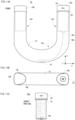
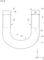
- a non-limiting example training instrument 10 of an embodiment according to the invention comprises a hollow main body 12, and the main body 12 is constituted by two gripping portions 12a and a coupling portion 12b.
- the main body 12 is formed in a U-letter shape when viewing from the front.
- the above-described gripping portions 12a are vertical bar portions of the U-letter of the main body 12, and the other portion (a curve line portion or curved portion of the U-letter) is the coupling portion 12b. That is, in this embodiment, the coupling portion 12b is non-movably coupled (joined) with each of the two gripping portions 12a.
- the main body 12 of this embodiment is integrally formed by a molding method described later, in fact, a process that the two gripping portions 12a and the coupling portion 12b are coupled (joined) to each other is not performed.
- the main body 12 is formed of an aluminum alloy, for example, and a thickness of the aluminum alloy is set to approximately 3 mm. This is for preventing the main body 12 from being plastically deformed even if a force (load) is applied thereto, which pushes the two gripping portions 12a in an opposite direction (pushing the two vertical bars of the U-letter inwardly), or pulls the two gripping portions 12a in a direction reverse to the opposite direction (pulling the two vertical bars of the U-letter outwardly), or twists the two gripping portions 12a in a direction perpendicular to the opposite direction (twisting the two vertical bars of the U-letter in a back-and-forth direction).
- a force load
- the main body 12 may be formed of titanium, stainless steel, carbon, etc.
- the cross-sectional shape of the main body 12 is formed in such a manner, when the user holds the main body 12 (training instrument 10) by the both hands and applies a force that pulls the two gripping portions 12a outwardly (in a separating direction), a joint of a finger can be hooked on a side corresponding to the above-described one vertex of the triangle located an inside. Moreover, when the user holds the main body 12 by the both hands and applies a force that pushes the two gripping portions 12a inwardly, it is possible to press a palm against an outside surface that is opposed to the side that the finger is hooked. Therefore, the user easily imposes (applies) a force.
- the cross-sectional shape of the main body 12 is not necessarily limited to a triangular shape with rounded corners, and may be a circular shape, other polygonal shape (square, pentagon, hexagon, etc.) with rounded corners, etc.
- the main body 12 comprises a control board 14 and a load sensor 16 that are incorporated in the main body 12.
- the load sensor 16 is arranged in a portion except the gripping portions 12a (the coupling portion 12b, in this embodiment), and is electrically connected to the control board 14 (processor 30) using a connector 16a and a cable 16b.
- the load sensor 16 is arranged inside the lowermost portion of the main body 12 formed in the shape of a U-letter shape(portion corresponding to a bottom side of the U-letter), i.e., a portion that the main body 12 curves.
- the load sensor 16 is arranged in a position that is an inside of the main body 12 and an outer periphery side of the curved portion.
- the control board 14 is provided inside a socket portion 18a inserted into one opening portion of the main body 12.
- the socket portion 18a (a socket portion 18b described later is also the same) is formed by a resin such as an epoxy resin, phenol resin, polyurethane, for example.
- the connector 14a is provided with a connector 14a into which the connector 16a is inserted.
- Various kinds of circuit components described later are mounted in this control board 14 (see Figure 3 ).
- the socket portion 18a is formed with a level difference that functions as a stopper when attached to the main body 12, and an LED lamp 20 of a ring shape is provided in this level difference portion.
- This LED lamp 20 is electrically connected to the control board 14 (processor 30).
- the socket portion 18a is provided with a connector 24 for connecting a charging cable for charging a secondary battery 34 (see Figure 3 ) as described later.
- FIG 2 is an illustration view showing an example of a training system 100 using the training instrument 10 shown in Figure 1 .
- the training system 100 includes the training instrument 10 and a portable terminal 110.
- the training instrument 10 and the portable terminal 110 are connected wireless-communicably.
- the training instrument 10 and the portable terminal 110 may be connected with a cable.
- the circuit components except the load sensor 16, the LED lamp 20, the power button 22, the connector 24 and the vibrating motor 52 are mounted on the above-described control board 14.
- the processor 30 manages overall control of the training instrument 10.
- the power supply circuit 32 supplies a power supply (voltage) from the secondary battery 34 to respective circuit components under instructions of the processor 30.
- the power supply circuit 32 includes a charge control circuit, and a charging voltage obtained by stepping down and rectifying commercial power source is supplied to the charging control circuit via the charging cable and the connector 24, whereby the secondary battery 34 can be charged by the charging control circuit.
- the RAM 36 is used as a buffer memory and a working memory of the processor 30.
- the flash memory 38 is a main storage of the training instrument 10, which stores a control program(s) of this training instrument 10, and stores information (correction value of load) unique of the training instrument 10, and stores the number of times of use of the training instrument 10 (number of measurement times of a load equal to or larger than a predetermined value).
- the wireless communication circuit 40 has a short-distance wireless communication function and wirelessly communicates with a further device (the portable terminal 110, in this embodiment) via the antenna 42 under the control of the processor 30.
- the wireless communication circuit 40 operates according to Bluetooth (registered trademark) standard.
- Wi-Fi Wireless Fidelity
- Wi-Fi is a name that has been certified by a predetermined certification organization concerning interconnectivity among wireless devices using communication standards of IEEE 802.11 series (IEEE 802.11a/b/g/n etc. ).
- the wireless communication circuit 40 may adopt mobile communication that conforms to the standard (specification) such as 3G (third generation) or 4G (fourth generation).
- 4G is also called LTE (Long Term Evolution).
- the training instrument 10 can communicate with a server 1002 described later directly or via a network 1004 (see Figure 18 ).
- the buzzer 44 is a general-purpose small electronic buzzer.
- the buzzer 44 is sounded under control of the processor 30.
- the gyro sensor 48 is an example of a motion (inertial) sensor, and is a three-axis gyro sensor of a piezo-electric vibration type, for example. However, as the gyro sensor 48, gyro sensors of other systems can be used.
- the gyro sensor 48 is provided in a manner capable of measuring each of angular velocities around the X axis, the Y axis and the Z axis for the training instrument 10. Data of the measured (detected) angular velocities are given to the processor 30. Therefore, based on the angular velocity detected by the gyro sensor 48, at least one of a tilt (posture) and motion of the main body 12 can be detected.
- the temperature sensor 50 is a general-purpose semiconductor temperature sensor, and measures a temperature of environment where the training instrument 10 is used (strictly, an inside of the main body 12). Data of the measured (detected) temperature is given to the processor 30.
- the LED lamp 20 is a lighting device using a general-purpose LED(s), and includes one or two or more LEDs emitting blue light and one or two or more LEDs emitting red light, for example.
- each LED is controlled by the processor 30 so as to be turned on, turned off or blinked. Therefore, the LED lamp 20 is turned on in blue or red color, or blinked in blue or red color, for example.
- the power button 22 is a push button, and inputs a signal to the processor 30 for turning on/off the power supply according to a depressing operation by the user. According to the signal for turning on/off the power supply, the processor 30 controls the power supply circuit 32, thereby to supply or stop the power supply to each circuit component.
- the wireless communication circuit 40 of the training instrument 10 performs mobile communication according to the standard (specification) like 3G or 4G (LTE)
- the mobile communication according to the standard (specification) like 3G or 4G (LTE) is adopted also for this first wireless communication circuit 132.
- the operation button 140 includes various kinds of manual operation buttons each of which is constituted by a push button.
- the operation button 140 includes a power button, a home button, a volume adjustment button, etc.
- the home button means a button for displaying a home screen or a main menu screen, and a function to return to a previous position is also assigned.
- the portable terminal 110 is a multifunctional information terminal, and various information processing terminals such as a smartphone, a tablet terminal, a notebook PC, a wearable terminal, etc. can be used as the portable terminal 110.
- various information processing terminals such as a smartphone, a tablet terminal, a notebook PC, a wearable terminal, etc.
- the portable terminal 110 is a smartphone, in the block diagram showing in Figure 4 , a circuit component for a telephone function is further provided.
- the portable terminal 110 performs connection processing with the training instrument 10.
- pairing is performed only when the connection processing is performed for the first time.
- devices in this example, the training instrument 10
- a user selects a device he/she wants to connect out of the searched devices and inputs the same identification number (authentication number) in both of the training instrument 10 and the portable terminal 110, whereby mutual authentication can be performed.
- an identification number is set in advance, and when performing the pairing in the training instrument 10, the identification number is automatically input.
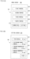
- the icon 212 is an icon for setting (registering or change) information (muscle power information) about a muscle power of a part of the user. If this icon 212 is touched, a setting screen 250 as shown in Figure 5(B) is displayed on the display 148. A display area 252, a display area 254, a display area 256 and a display area 258 are provided in the setting screen 250 aligned vertically. Moreover, an icon 260 is displayed on the setting screen 250 below the display area 258.
- the icon 260 is an icon for displaying a video that explains a measurement method of measuring a maximum load of each part. For example, when the icon 260 is touched after the display area (252, 254, 256 and 258) corresponding to a part (muscle) to be set is touched, a video of the measurement method that measures the maximum load of the part to be set is displayed on the display 148.
- a selection screen 300 capable of selecting contents of training for performing training with the first purpose is displayed on the display 148.
- an icon 302, an icon 304 and an icon 306 are displayed on the selection screen 300. Moreover, an icon 308 is displayed on a lower part of the selection screen 300.
- the icons 302-306 are icons for selecting training. Specifically, the icon 302 is an icon for selecting isometric 1.
- the icon 304 is an icon for selecting slow training 1.
- the icon 306 is an icon for selecting a squat beginner class.
- a mark indicating it is displayed in a manner superposed on a corresponding icon (here, icons 302, 304 or 306), or the corresponding icon is displayed in a gray out manner. For example, when the same training is performed a predetermined number of times or a predetermined condition is satisfied by performing training, it is determined that the training is ended.
- a training screen 350 for performing training of the isometric 1 is displayed on the display 148. Moreover, instructions about the training are output from the speaker 152 by voice if needed.
- a difference between the measured current load value and the instructed load value (target load value) is detected, and the accuracy of the load is calculated.
- a difference between the calculated posture of the user and the correct posture of training is detected, and the accuracy of the posture is calculated. According to such the accuracy, advice on the training is presented to the user. Therefore, the user can adjust the load to be applied to the training instrument 10, and correct his/her posture in the training.
- an acceleration and an angular velocity in a state where the user correctly holds the training instrument 10 and stands up with a posture that becomes a base are stored as a reference acceleration and a reference angular velocity, and by comparing them with a current acceleration and a current angular velocity, the current posture can be detected (calculated).
- the posture means a tilt with respect to the horizontal plane or the vertical plane about a part of the user to be paid attention.
- contents of instructions about the training concerned are output with a voice, as described above.
- a voice having contents such as "hold ⁇ sec. with load of ⁇ O% of maximum load" is output from the speaker 152.
- about the contents of the instructions for the training may be displayed on the display 148 in a text, instead of a voice or together with a voice. The same applied in the following.
- numerals correspond to O and ⁇ are values by taking a past training result into consideration, and automatically determined based on information of them by the training program so that excessive training can be prevented and the training can be performed safely.
- the same is applied to a case where the contents of instructions for further training are output with a voice.
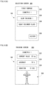
- Figure 7(A) shows an example of a training screen 400 about the slow training 1
- Figure7 (B) shows an example of a training screen 450 about the squat beginner class
- Figure 8 shows an example of a training screen 500 for a squat upper class.
- the training screen 400 shown in Figure 7(A) is displayed on the display 148.
- a display area 402 a display area 404 and a display area 406 are provided in the training screen 400.
- a display area 410 is provided below the display area 406.
- the display area 402 is an area for displaying the current load.
- the display area 404 is an area for displaying the accuracy of the current posture.
- the display area 406 is an area for displaying the number of reciprocation times of the current motion.
- the display area 410 is an area for displaying how to perform the slow training with an animation.
- the animation displayed in the display area 410 shows that the training instrument 10 is held by both hands in front of a chest, that a force is applied so that both hands are brought close to each other, and that a force is applied so that both hands are kept away from each other, and that the training instrument 10 is reciprocately moved by being slowly moved left and right in parallel with a floor (ground).
- a voice having contents such as "move left and right with interval of ⁇ sec. with load of ⁇ % of maximum load" is output from the speaker 152.
- the training screen 450 shown in Figure 7(B) is displayed on the display 148.
- a display area 452 a display area 454 and a display area 456 are provided in the training screen 450.
- a display area 460 is provided below the display area 456.
- the display area 452 is an area for displaying a current thigh angle.
- the angle is the thigh angle at the time of rendering a level (plane parallel to horizontal surface) 0 (zero) degrees, and when the user is standing upright, the angle becomes approximately 90 degrees, for example.
- the display area 454 is an area for displaying the accuracy of the current posture.
- the display area 456 is an area for displaying the number of times of squat.
- the display area 410 is an area for displaying how to perform a squat with an animation.
- the animation displayed in the display area 410 shows, for example, that from a standing upright state, bend and stretch so that the knee does not come out in front of the tiptoe, sitting down until the knee reaches 90 degrees, then return to the upright state.
- a voice having contents such as "move up and down with interval of ⁇ sec. while pressing training instrument against thigh" is output from the speaker 152.
- a training screen 500 shown in Figure 8 is displayed on the display 148.
- a display area 502, a display area 504 and a display area 506 are provided in the training screen 500.
- a display area 510 is provided below the display area 506.
- the display area 502 is an area for displaying the current load.
- the display area 504 is an area for displaying the accuracy of the current posture.
- the display area 506 is an area for displaying the number of squat times.
- the display area 510 is an area for displaying how to perform the squat with an animation.
- the animation displayed in the display area 510 shows that the training instrument 10 is held by both hands in front of a chest, that a force is applied so that both hands are brought close to each other, and that a force is applied so that both hands are kept away from each other, and that the squat is performed while holding the training instrument 10 in front of the chest.
- the accuracy of an angle of an upper body (the accuracy of posture) in a state where a load of ⁇ % of the maximum load is applied to the training instrument 10 is calculated. Therefore, in the squat upper class, the number of squat times can be calculated from a change of the acceleration of the Y-axis direction of the acceleration sensor 46.
- a voice having contents such as "move up and down with interval of ⁇ sec. while holding training instrument in front of chest with applying load of ⁇ % of maximum load" is output from the speaker 152.
- the training screens (200, 250, 300, 350, 400, 450 and 500) shown in Figure 6 - Figure 8 are exemplified about some training, and should not be limited.
- a training screen is prepared for each training, and a design and contents of the training screen can be changed as appropriate.
- loads and postures (angle of parts) detected during training are displayed as numerical values in Figure 6 - Figure 8
- the loads and postures may be displayed with images.
- the current posture of the user during training is displayed using an avatar.
- the current posture of the user is displayed in the display area 460 using an avatar.
- an upright avatar is displayed in the display area 460 as shown in Figure 9(A) , and it is indicated by an angle image displayed beside the avatar that its thigh forms an angle of 90 degrees with respect to the horizontal.
- the angle image means an image that a fan shape image having a size corresponding to the angle to be displayed is superimposed on an image imitating a part of a protractor.
- a thigh of a right leg is a part to be paid attention, and measuring the angle of this part is instructed, and the user performs the squat while pressing the training instrument 10 against the thigh of the right leg.
- the detected posture here, angle of thigh
- the avatar is displayed so that it can be visually recognized that a part to be paid attention is a thigh.
- a spot pattern is applied to the thigh of the right leg of the avatar in Figures 9(A) and 9(B) .
- the user can know at a glance whether the posture is correct and at a glance how the posture should be corrected. Therefore, it is possible to lead the user so that effective training can be performed.
- advice is presented to the user.
- a voice such as “strongly” or “little more strongly” is output from the speaker 152.
- a voice such as “weakly” or “little more weakly” is output from the speaker 152.
- a voice such as "good” or “keep it” is output to the speaker 152.
- the score or evaluation is calculated (determined) in accordance with the load, the accuracy of the posture, stability, the number of times, etc.
- information on the reward to be distributed is displayed on the display 148 along with the score (evaluation) of the training.
- the reward may be an avatar item, a training program, a virtual coin that can be used in other application programs, etc. Detailed description of determination on whether a reward is to be distributed, distribution processing, etc. will be described later.
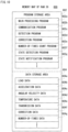
- FIG 10 shows an example of a memory map 600 of the RAM 36 incorporated in the training instrument 10 shown in Figure 3 .
- the RAM 36 includes a program storage area 602 and a data storage area 604.
- the program storage area 602 is stored with a control program of the training instrument 10.
- This control program is constituted by a main processing program 602a, a communication program 602b, a detection program 602c, a correction program 602d, a number-of-times count program 602e, a state detection program 602f, a state notification program 602g, etc.
- the main processing program 602a is a program for processing a main routine that controls the training instrument 10.
- the communication program 602b is a program for performing communications with other apparatus (portable terminal 110 in this embodiment).
- the detection program 602c is a program for detecting measurement values of the load sensor 16, the acceleration sensor 46, the gyro sensor 48 and the temperature sensor 50.
- the correction program 602d is a program for correcting, using correction data 604f, the measurement value of the load sensor 16 detected according to the detection program 602c. At this time, the measurement value of the temperature sensor 50 is taken into consideration.
- the number-of-times count program 602e is a program for counting the number of times (number of measurement times) that the load equal to or larger than a predetermined value (load causing deformation of the strain gauge) is detected by the training instrument 10. However, when the load is changed to the load equal to or larger than the predetermined value, the number of measurement times is counted, if the load equal to or larger than the predetermined value continues, the number of measurement times is not counted.
- the state detection program 602f is a program that detects an operating state (start, stop, charge, communication, overload, etc.), a battery residual quantity and an exhaustion state of the training instrument 10.
- the start or stop of the training instrument 10 is detected based on a signal of on/off of the power button 22.
- the processor 30 can grasp whether the training instrument 10 is under communication.
- the battery residual quantity can be known by detecting a voltage value of the secondary battery 34, for example.
- the exhaustion state is detected based on the number of measurement times detected according to the number-of-times count program 602e.
- the overload is detected if the measurement value of the load sensor 16 exceeds a predetermined threshold value (150 kg, for example).
- the state notification program 602g is a program for notifying, by making operate at least one of the blinking of the LED lump 20, the sounding of the buzzer 44 and the driving of the vibration motor 52 according to various kinds of states such as the operating state, the battery residual quantity, the exhaustion state, the overload, etc. detected according to the state detection program 602f, the various kinds of states.
- the LED 20 is controlled an emitting color and the lighting or blinking thereof.
- the buzzer 44 is controlled the number of times of sounding and temporal duration thereof.
- the vibration motor 52 is controlled the number of driving times and temporal duration thereof.
- load data 604a acceleration data 604b, angular velocity data 604c, temperature data 604d, transmission data 604e, correction data 604f and number-of-times data 604g are stored in the data storage area 604.
- the load data 604a is data of a measurement value of the load sensor 16 detected by the detection program 602c. That is, it is data of a load (load value) applied to the main body 12.
- the acceleration data 604b is data of a measurement value of the acceleration sensor 46 detected by the detection program 602c.
- the angular velocity data 604c is data of a measurement value of the gyro sensor 48 detected by the detection program 602c.
- the temperature data 604d is data of a measurement value of the temperature sensor 50 detected by the detection program 602c.
- the transmission data 604e is data to be transmitted to the portable terminal 110.
- the transmission data 604e is data including the load data 604a that is corrected according to the correction program 602d, the acceleration data 604b and the angular velocity data 604c.
- the correction data 604f is data for correcting the detected load data 604a.
- the main body 12 is formed by bending a pipe-shaped aluminum alloy, and the load sensor 16 (strain gauge) is affixed on an interior of the main body 12. Therefore, respective training instruments 10 (main body 12) have individual differences.
- the correction data 604f includes data that corrects the load data 604a in order to absorb the individual difference etc. Such a correction value is determined based on a difference between the load measured by the load sensor 16 and the predetermined load actually applied to the main body 12.
- the correction data 604f includes data that corrects the load data 604a in order to absorb the error due to the temperature.
- the correction data 604f may be stored (saved) within the processor 30.
- the number-of-times data 604g is data on the number of measurement times that is counted according to the number-of-times count program 602e when the load equal to or larger than or equal to the predetermined value is detected by the load sensor 16. Since the number of measurement times is cumulatively counted, when the power of the training instrument 10 is turned on, it is read from the flash memory 38 and stored in the RAM 36, and when the power of the training instrument 10 is turned off, stored in the flash memory 38. In addition, along with the number of measurement times, the load detected for each time may also be stored.
- data storage area 604 data such as data of a lighting pattern of the LED lamp 20, data of a sounding pattern of the buzzer 44, data of a driving pattern of the vibrating motor 52, etc. are stored, and a timer(s) (counter(s)) and a flag(s) necessary to execute the control program are provided.
- FIG 11 shows an example of a memory map 700 of the RAM 128 of the portable terminal 110 shown in Figure 4 .
- the RAM 128 includes a program storage area 702 and a data storage area 704.
- the program storage area 702 is stored with an information processing program of the portable terminal 110d.
- This information processing program is constituted by a main processing program 702a, a communication program 702b, an image producing program 702c, an image display program 702d, a sound output program 702e, a training program 702f, etc.
- the main processing program 702a is a program for processing a main routine that controls the portable terminal 110.
- the communication program 702b is a program for performing communications with other apparatus (training instrument 10 in this embodiment) using the first wireless communication circuit 132, or with other apparatus (PC, a server, etc.) via the wireless LAN using the second wireless communication circuit 136.
- the image producing program 702c is a program by which the GPU produces, on the VRAM, in the display control circuit 146 under instructions of the processor 120, display image data corresponding to various kinds of screens (200, 250, 300, 350, 400, 450, 500, etc.) to be displayed on the display 148 using image producing data 704a described later.
- the image display program 702d is a program by which the GPU outputs, in the display control circuit 146 under instructions of the processor 120, the display image data produced according to the image producing program 702c to the display 148.
- the sound output program 702e is a program for outputting sound data 704d described later to the speaker 152 via the D/A converter 150.
- the sound data 704d is data for outputting a plurality of kinds of messages with a voice, and is output selectively.
- the training program 702f is an application program for performing training of this embodiment.
- program storage area 702 other application programs such as an application program about an email, are stored. Moreover, when the portable terminal 110 is a smartphone, a program for performing a telephone call function is also stored.
- image producing data 704a, setting data 704b, target value data 704c, sound data 704d, measurement data 704e and history data 704f are stored in the data storage area 704.
- the image producing data 704a includes data for producing the display image data, such as polygon data, texture data, icon image data, animation data, avatar data, data of an avatar item, etc.
- the setting data 704b is numeral data about a maximum load for each part that is set in the setting screen 250. However, NULL data is described for a part that the maximum load is not set.
- the target value data 704c is numeral data about a target value of the maximum load for each part that is set by the training program 702f.
- the target value is set, per purpose of training, based on the sexuality and age of the user, and a training history of the user and so on.
- the target value may be set by the user.
- the sound data 704d is data about synthetic sound for outputting a plurality of messages instructing the contents of training and a plurality of messages for advising on training with a voice.
- the measurement data 704e is data that the transmission data 604e transmitted from the training instrument 10 are stored according to the time series. That is, the measurement data 704e is data that the load data detected and corrected by the training instrument 10, the acceleration data and the angular velocity data are accumulated in time series.
- the history data 704f is data on a training history, in which data concerning the date and time (time) of the training, a content of the training, a load (load value) and posture (also including acceleration and angular velocity) detected during the training and the accuracy of the posture when performing the training are described in time series for each training.
- the icon 308 is touched in the selection screen 300, the training history is displayed on the display 148 according to the history data 704f.
- the date and time information included in the history data 704f is acquired from the RTC 120a when the transmission data 604e is received, and added to the transmission data 604e (measurement data 704e).
- the data storage area 704 other data required for execution of the information processing program is stored and a timer(s) (counter(s)) and a flag(s) are provided.
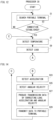
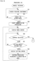
- Figure 12 - Figure 14 are flow charts of control processing of the processor 30 of the training instrument 10 shown in Figure 3 .
- processing in respective steps in the flow charts shown in Figure 12 - Figure 14 are mere examples, and if the same result is obtained, an order of the respective steps may be changed.
- the processor 30 executes the processing of each step of the flowcharts shown in Figure 12 - Figure 14 ; however, some steps may be executed by a processor(s) other than the processor 30 or a dedicated circuit(s).
- the processor 30 starts the control processing.
- the processor 30 searches the portable terminal 110 in a step S1.
- a next step S3 it is determined whether connection is established. If "NO” is determined in the step S3, that is, if connection is not established, the process directly returns to the step S1.
- connection processing can be manually performed on a side of the portable terminal 110 later, and therefore, if "NO" is determined in the step S3, after waiting for a predetermined time period, 10 seconds to 30 seconds, for example, the process may be returned to the step S1.
- "YES" is determined in the step S3, that is, if connection is established, the process proceeds to a step S7.
- a temperature is detected. That is, the processor 30 acquires a measurement value of the temperature sensor 50 and stores corresponding temperature data 604d into the data storage area 604.
- a load is detected. That is, the processor 30 acquires a measurement value of the load sensor 16 and stores corresponding load data 604a into the data storage area 604.
- the processor 30 determines whether the load detected in the step S9 exceeds a maximum value (150 kg, for example) that a developer of the training instrument 10, etc. assumes.
- step S11 If “NO” is determined in the step S11, that is, if there is no overload, the process directly proceeds to a step 15. On the other hand, if "YES” is determined in the step S11, that is, if there is an overload, in a step S13, in order to notify an overload, the processor 30 makes the buzzer 44 sound, and the process proceeds to the step S15.
- the buzzer 44 is sounded when notifying an overload, instead of the buzzer 44 sounding, the LED lamp 20 may be made to be lighted or blinked in a predetermined color, or the vibrating motor 52 may be made to be driven.
- an overload may be notified by any two or more of sounding of the buzzer 44, lighting (blinking) of the LED lamp 20 and driving of the vibrating motor 52. This is also true for a case where urging (informing) replacement of the training instrument 10 as described later.
- the processor 30 determines whether a load detected by the load sensor 16 is changed from a load of 0 (zero) or less than the predetermined value to a load equal to or larger than the predetermined value.
- the predetermined value is a reference value used for judgment to urge the replacement of the training instrument 10, as described later.
- step S15 determines whether the load is less than the predetermined value or the load equal to or larger than the predetermined value continues. If “NO” is determined in the step S15, that is, if the load is less than the predetermined value or the load equal to or larger than the predetermined value continues, the process directly proceeds to a step S23 shown in Figure 14 .
- step S15 determines whether the load is changed to a load equal to or larger than the predetermined value.
- the number of measurement times of the load is incremented by 1 (one) in a step S17, and it is determined, in a step S19, whether the number of measurement times reaches the predetermined number of times (15000 times, for example).
- step S19 If “NO” is determined in the step S19, that is, the number of measurement times does not reach the predetermined number of times, the process proceeds to the step S23. On the other hand, if "YES” in the step S19, that is, if the number of measurement times reaches the predetermined number of times, the buzzer 44 is made to be sounded in a step S21 in order to urge (notify) the replacement of the training instrument 10, and the process proceeds to the step S23.
- the training instrument 10 of this embodiment when the number of times that the load becomes equal to or larger than a predetermined value becomes the predetermined number of times (15000 times, for example), it is determined that a life of the training instrument 10 (load sensor 16) has come, and therefore, the replacement of the training instrument 10 is urged. This is because the load cannot be accurately measured due to metal fatigue of the main body 12 or deterioration of the load sensor 16 (strain gauge) or both factors.
- An acceleration is detected in the step S23 shown in Figure 14 . That is, the processor 30 acquires a measurement value of the acceleration sensor 46 and stores corresponding acceleration data 604b into the data storage area 604.
- An angular velocity is detected in a step S25. That is, the processor 30 acquires a measurement value of the gyro sensor 48 and stores corresponding angular velocity data 604c into the data storage area 604. Then, in a step S27, transmission data 604e is produced by correcting the load, acceleration and angular velocity. Here, the processor 30 corrects with using the correction value the detected load with reference to the correction data 604f.
- the transmission data 604e including the corrected load data 604a, acceleration data 604b and angular velocity data 604c is produced. Then, the transmission data 604e is transmitted to the portable terminal 110 in a step S29, and the process returns to the step S7 shown in Figure 12 .
- the processor 30 controls lighting/putting-out of the LED lamp 20 according to turning on/off of the power supply, and changes a color that the LED lamp 20 is lighted according to battery residual quantity. Moreover, the processor 30 makes the LED lamp 20 blink by a predetermined color during communication.
- step S53 it is determined whether connection with the training instrument 10 is established.
- step S53 If “NO” is determined in the step S53, that is, if connection with the training instrument 10 is not be established, the process returns to the step S51. On the other hand, if "YES” is determined in the step S53, that is, if connection with the training instrument 10 is established, communication processing is started in a step S55. That is, although illustration is omitted, in parallel to processing of a training program, the processor 120 performs communication processing and receives the transmission data transmitted from the training instrument 10 so as to additionally store as the measurement data 704e in the data storage area 704 in a time series.
- a next step S57 the menu screen 200 as shown in Figure 5(A) is displayed on the display 148.
- a step S59 it is determined, in a step S59, whether a purpose of training is selected.
- the processor 120 determines whether any of the icons 202-208 is touched. However, the processor 120 determines that the icon (202, 204, 206 and 208) displayed on a position that touch coordinate data from the touch panel 144 indicates. In the following, this is true for a case where other icons and display areas is touched.
- step S59 determines whether the purpose of training is selected. If “YES” is determined in the step S59, that is, if the purpose of training is selected, the process proceeds to a step S71 shown in Figure 16 . On the other hand, if "NO" is determined in the step S59, that is, if a purpose of training is not selected, it is determined, in a step S61, whether it is a setup of muscle power information. Here, the processor 120 determines whether in the icon 212 is touched.
- step S61 If "NO" is determined in the step S61, that is, if it is not a setup of muscle power information, the process returns to the step S59.
- illustration is omitted, but when touching the icon 210 in the menu screen 200, the connection processing with the training instrument 10 is performed.
- the icons 202-208 are displayed in an untouchable state prior to connection processing with the training instrument 10 is established, and if connection with the training instrument 10 is established, the icons 202-208 are changed into a touchable state.
- step S61 determines whether it is a setup of muscle power information. If “YES” is determined in the step S61, that is, if it is a setup of muscle power information, after displaying the setting screen 250 as shown in Figure 5(B) on the display 148 in a step S63 and performing setting processing in a step S65 according to an operation of the user, the process returns to the step S57.
- a maximum load of a part to be set is registered (set or changed) in the step S65.
- the muscle power information that is set here is stored (updated) as the setting data 704b in the data storage area 704.
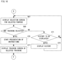
- a purpose of training is selected in the menu screen 200 as described above, as shown in Figure 16 , the selection screen 300 as shown in Figure 6(A) about the selected purpose on the display 148 in the step S67.
- a next step S69 it is determined whether there is any selection of training.
- the processor 120 determines whether any of the icons 302-306 is touched in the selection screen 300.
- step S71 determines whether a history is to be displayed.
- the processor 120 determines whether the icon 308 is touched. If "NO” is determined in the step S71, that is, if it is not display of history, the process directly returns to the step S67. On the other hand, if "YES” is determined in the step S71, that is, if it is the display of history, after displaying a history corresponding to the history data 704f on the display 148 in a step S73, the process returns to the step S67. However, in fact, if there is an instruction from the user, the display of history is ended, and the process returns to the step S67.
- step S69 presentation of instruction content about the selected individual training is started in a step S75.
- step S75 presentation of instruction content about the selected individual training is started in a step S75.
- the training screen 300, 350, 400, 450, 500, etc.
- Figure 6 - Figure 8 about the selected individual training on the display 148 in a step S77
- the process proceeds to a step S79 shown in Figure 17 .
- the training screen an animation about how to perform the individual training is displayed, and the instruction about the individual training is output from the speaker 152 with a voice.
- the load and the number of times both included in the instruction are automatically determined by the training program 702f.
- the user holds the training instrument 10 and performs a predetermined motion or maintains a predetermined posture while applying the load to the training instrument 10 being held.
- the user merely holds the training instrument 10 and may not apply the load.
- steps S75-S93 are performed about the individual training that is selected in the selection screen 300. Therefore, in fact, there is provided with processing (program) for each individual training.
- a measurement value is acquired.
- the processor 120 acquires the transmission data 604e that is transmitted from the training instrument 10 and received by the antenna 134 and the first wireless communication circuit 132 so as to additionally stores as the measurement data 704e.
- a next step S81 it is determined whether the measurement value is accumulated for a predetermined time period (0. 5 seconds, for example). However, since the processor 120 performs processing with using the measurement values for each predetermined time period, this predetermined time period means a time period after performing the processing using the measurement values at a previous time.
- step S81 determines whether the load exceeds the presented load, and when the load is less than the presented load, calculates a difference therebetween.
- a posture of the user is detected from at least one of the acceleration and the angular velocity that are indicated by the measurement data 704e. If saying strictly, the processor 120 detects angles of a predetermined part of the user with respect to a horizontal direction and a vertical direction from the acceleration and the angular velocity.
- a step S87 accuracy of the posture is calculated.
- the processor 120 calculates a degree of coincidence between the posture of the user that is detected in the step S85 and a correct posture that is set in advance in the training program 702f.
- a subsequent step S89 the user is presented with at least one of the detected load and the detected posture.
- the processor 120 performs processing that displays a numeral value of the load that the user currently applies to the training instrument 10 and the detected current posture (angle of the part to be paid attention) of the user, performs processing that displays the accuracy of the posture, and performs processing that displays temporal duration and the number of times of motion.
- the processor 120 performs processing that displays the current posture of the user with using an avatar, and performs processing that outputs with a voice advice to strengthen or weaken the load and advice to increase or decrease a bending angle of a joint.
- step S93 it is determined, in a step S93, whether it is an end of training.
- the processor 120 determines whether the user performs the selected training to the last, or whether an instruction to end the training is given by the user. If "NO” is determined in the step S93, that is, if it is not the end of training, the process returns to the step S79. On the other hand, if "YES” is determined in the step S93, that is, if it is the end of training, it is determined, in a step S95, whether it is an end of the training program 702f. Here, it is determined whether the end of the training program 702f is instructed by the user.
- step S95 If “NO” is determined in the step S95, that is, if it is not the end of the training program 702f, the process returns to the step S67 shown in Figure 16 . That is, the display returns to the selection screen 300 of individual training according to the selected purpose. However, the process may be returned to the step S57 (menu screen 200).
- step S95 if "YES” is determined in the step S95, that is, if it is the end of the training program 702f, information on the training at this time is saved in a step S97, and the muscle training processing is terminated.
- the processor 120 saves the date and time (time) of the training, the content of training, the load and the posture (including acceleration and angular velocity) that are detected from the transmission data 604e (measurement data 704e) received from the training instrument 10 during the muscle training processing, and the data about the accuracy of the posture when performing the training concerned in the HDD 130, as history data, or add these to the history data having been saved in the HDD 130.
- the information on the training may be saved in the HDD 130 at an arbitrary timing according to an instruction of the user.
- the load sensor, the acceleration sensor and the gyro sensor in the training instrument capable of being held by both hands, and the load applied to the training instrument is detected and the posture and the motion of the training instrument are detected, and therefore, in performing the training, there is no constraint on the posture and the motion of the user due to a problem of a configuration of the training instrument. Therefore, it is possible to make various kinds of training performable. That is, it is possible to expand the range of training.
- a general-purpose portable terminal such as a smartphone can be used.
- a portable terminal such as a smartphone in addition to the training instrument, and therefore, it is not necessary to provide a dedicated system.
- the portable terminal since the portable terminal has no choice of an installation place under a situation capable of performing a communication with a base station, a place of training is not restricted.
- the acceleration sensor and the gyro sensor in order to detect at least one of the tilt (posture) and motion of the main body of the training instrument in this embodiment, even if providing only either, at least one of the tilt (posture) and motion of the main body can be detected.
- the measurement value for the predetermined time period is accumulated on a side of the portable terminal in this embodiment, the measurement value for the predetermined time period may be accumulated on a side of the training instrument, and be transmitted to the portable terminal.
- the load is corrected on a side of the training instrument in this embodiment
- the load may be corrected on a side of the portable terminal.
- the correction value is transmitted to the portable terminal from the training instrument, and stored in the portable terminal.
- the data of the detected temperature is also transmitted to the portable terminal, in this case.
- the current load and the accuracy of the posture are presented to the user during the training, the current load, the posture and the accuracy of the posture are calculated in the portable terminal; however, when presenting to the user a change of the load and a change of the accuracy of the posture after ending of the training, the load, the posture and the accuracy of the posture may be calculated by a further computer different from the portable terminal.
- the further computer corresponds to a server 1002 (see Figure 18 ) described later.
- the load data, the acceleration data and the angular velocity data that are detected during the training are transmitted from the portable terminal to the further computer (server 1002).
- the current load, the accuracy of the posture, etc. are presented to the user during the training in this embodiment by performing at least one of a screen display and a voice output in the portable terminal 110, it does not need to be limited to this.
- the load and that the posture is correct or incorrect may be notified (presented) by means of at least one of the blinking of the LED lamp 20, the sounding of the buzzer 44 and the driving of the vibration motor 52. Therefore, the training instrument 10 may be configured to provide with any one of the LED lamp 20, the buzzer 44 and the vibrating motor 52.
- the load and the accuracy of the posture may be determined by the processor 120 of the portable terminal 110, and a determining result may be transmitted to a side of the training instrument 10.
- the training instrument shown in this embodiment is a mere example, and should not be limited.
- it may be provided with a speaker in the training instrument.
- a D/A converter is mounted on a control board incorporated in the main body of the training instrument in a manner capable of performing communication with the processor, and the speaker is connected to this D/A converter.
- the buzzer may be omitted.
- the speaker is operated to exert the same function as the buzzer described in the above embodiment.
- a sound or voice (music) that is output from the speaker provided in the portable terminal may be output from the speaker provided in the training instrument instead of the speaker provided in the portable terminal or along with the speaker provided in the portable terminal. In such a case, sound data corresponding to the sound or voice that is output from the speaker is transmitted to the training instrument from the portable terminal.
- the history data is stored in the portable terminal in this embodiment, such information may be managed by a further computer different from the portable terminal.
- a server that provides a predetermined service may manage the history data. An example of a system using such a server will be described.
- a network system 1000 shown in Figure 18 includes a server 1002.
- This server 1002 is a general-purpose server, and comprises a CPU 1010 and a memory 1012.
- the memory 1012 includes an HDD, ROM and RAM. Although illustration is omitted, the server 1002 is provided with further circuit components such as a communication module, etc.
- the server 1002 is connected with two or more portable terminals 110 communicably.
- a database (measurement value DB) 1006 is directly connected to the server 1002.
- the measurement value DB 1006 is provided outside the server 1002 in the example shown in Figure 18 , it may be provided inside the server 1002.
- the server 1002 and the measurement value DB 1006 may be connected communicably through the network 1004.
- the server 1002 manages the measurement value for each user using the measurement value DB 1006.
- information to be managed includes a user ID, a user name, sexuality, generation (age), a friend, a mail address, a training history, etc.
- the user accesses using the portable terminal 110, for example a site that is operated by the server 1002, thereby to register the user information, i.e., the user name, the sexuality, the age and the mail address. Moreover, the user registers his/her friend user (a user name or user ID) if needed. Then, after the user performs training, according to an operation of the user, or automatically, the portable terminal 110 transmits data (result data) about a result of the training at this time to the server 1002.
- the portable terminal 110 transmits data (result data) about a result of the training at this time to the server 1002.
- the result data is data about the training result that includes the date and time (time) of the training, a content of the training, a load (load value) and posture (also including acceleration and angular velocity) detected during the training and the accuracy of the posture when performing the training.
- the server 1002 receives the result data, and updates the training history (history data) in the measurement value DB 1006 corresponding to the user (user ID).
- the user ID is unique identification information for identifying a user, and in order to manage the above-described information for each user by the server 1002, for example, it is given to the user or the portable terminal 110 that the user concerned uses.
- the user name is a name or nickname etc. of the user.
- the sexuality is distinction of a man or a woman.
- the friend is a user name or a user ID of a further user who is registered by the user as a friend.
- a person capable of being registered as a friend is limited to a user who utilizes this site.
- friends need not be restricted to real-world friends in a strict sense, but may be family members or company colleagues.
- a mail address is basically a mail address that is set in the portable terminal 110 that the user uses, may be a mail address that is set in a further terminal that the user concerned uses. Since the history of training is the content of the above-described history data, duplicate description is omitted here.
- the server 1002 can provide a service in accordance with the result of training (result data), which includes distributing an additional application capable of performing further training, distributing purchase benefit of other applications, giving points (virtual coins) that can be used for purchasing applications, or distributing an avatar, an avatar item, etc.
- the application, the purchase benefit, the virtual coins and the avatar and avatar item that the server 1002 distributes are collectively called "contents". If doing this way, it is thought that motivation for the user to perform the training or the user to continuously perform the training can be enhanced.
- the server 1002 determines, using reward information (gift information) as shown in Figure 20 , whether a reward (digital or analog contents) is to be distributed, and determines a reward to distribute.
- Table data of reward information as shown in Figure 20 is stored in the memory 1012, and the CPU 1010 performs, with reference to this table data, reward determination processing (see Figure 21 ) described later.
- the distribution condition includes a kind of training, a level (menu) of training, a score (evaluation) of training and the number of continuing days. However, all of the level of training, the score of training and the number of continuing days do not need to be imposed as the distribution condition, and any one or two combination may be sufficient.
- items that are not imposed as distribution conditions are indicated by drawing cross bars.
- the above-described type (identification information) of training is described in a column of the type of training.
- numeral values (1, 2 --) of levels and menu information beginninger class, middle class, upper class, etc.
- a range (standard value) of the score (evaluation) is described in a column of the score (evaluation) of training.
- a standard value of days (duration) is described in a column of the number of continuing days.
- distributing a reward A is determined.
- distributing a reward E is determined. Descriptions are omitted, but the same applies to other cases.
- the server 1002 When distributing a reward is determined, if a reward is digital data, the server 1002 sets the data concerned in a downloadable manner to the user (user ID) who gains the reward, and notifies to the portable terminal 110 that the user concerned owns by email that the user gains the reward and that the user can download the reward, and so on.
- a manager of the server 1002 etc. arranges for sending the goods to the user who gains the reward, and notifies to the portable terminal 110 that the user concerned owns by an email that the user gains the reward and that the reward is sent to the user, and so on.
- the reward information (distribution condition) shown in Figure 20 is a mere example, and should not be limited. For example, even when the distribution condition does not include the number of continuing days, it may be determined whether a reward is to be distributed based on not only the result of this training but the result of the past training, i.e., the training history.
- a reward in consideration of not only the distribution condition but the user information, it may be determined whether a reward is to be distributed, and a reward to be distributed.
- the user information not only the age and sexuality but also presence or absence of exercise experience, nationality, residential area, etc. may be taken into consideration.
- the presence or absence of exercise experience, the nationality, the residential area, etc. are included in the management information.
- the CPU 1010 of the server 1002 performs reward determination processing shown in Figure 21 . It should be noted that the reward determination processing is performed for each portable terminal 110 by which the result data is transmitted. Therefore, if the server 1002 receives the result data from the portable terminal 110, as shown in Figure 21 , the CPU 1010 starts the reward determination processing for the portable terminal 110 concerned.
- a step S201 the training history of training corresponding to the user ID concerned is updated by the received result data.
- a next stepS203 it is determined whether there is any reward that satisfies a distribution condition through reception of a result of training.
- the CPU 1010 determines, with reference to the reward information, whether there is any reward that satisfies a distribution condition.
- step S203 If “NO” is determined in the step S203, that is, if there is no reward satisfying a distribution condition, the reward determination processing is ended. On the other hand, if "YES” is determined in the step S203, that is, if there is a reward satisfying a distribution condition, reward distribution processing is performed in a step S205.
- the CPU 1010 sets so that the portable terminal 110 (user) having transmitted the result data can download digital data as a reward, or sends an email addressing a terminal of a person in charge that notifies to the user of the portable terminal 110 having transmitted the result data arrangement of delivery of a reward goods.
- the CPU 1010 sends an email to the portable terminal 110 having transmitted the result data, which notifies that the digital data of the reward becomes downloadable, or that arrangement for delivering the reward goods is performed.
- the server 1002 can also provide various services for a user with using the training history.
- the server 1002 can provide various kinds of services, such as presenting a training history in graph form or the like (spreadsheet), presenting an absolute evaluation (change in the maximum load for each part) based on the result of training, introducing recommended training, introducing training books, diet books, etc., and so on.
- presenting a training history in graph form or the like swipesheet
- presenting an absolute evaluation change in the maximum load for each part
- the server 1002 can provide services, such as presenting the average value of the calculated maximum load, the extracted maximum value, the extracted minimum value, etc. for each category of sexuality, age, etc., presenting a comparison result of the training history compared with a further user that has a profile similar to the user and/or a further user that the user registers as a friend, and presenting a ranking. For example, a comparison result about the accuracy of the posture or training progress is presented.
- the server 1002 can also provide such a service that advises on the training progress of the user based on at least one of the training history of the user and the comparison result of the training history with those of the further user.
- the server 1002 can also provide a service that notifies to the user a further user who is performing training at the same time as the user among other users having been registered as a friend.
- a service that notifies to the user a further user who is performing training at the same time as the user among other users having been registered as a friend.
- information related to a further user or a training history of the further user is presented to the user, such as presenting the average value of the calculated maximum load value, the extracted maximum value, the extracted minimum value, etc. for each category, presenting a comparison result of the training history with those of the further user, presenting a ranking.
- training histories and training progress of the user and the further user may be presented without comparing.
- the user compares own training history (result) with the training history (result) of the further user, or compares own training progress with training progress of the further user.
- the training history (result) and the training progress it is not necessary to simultaneously present those of the user and those of the further user, and may be switchedly presented according to an operation of the user.
- it is possible to present the training history and the training progress for a further user with some relevance such as having a profile similar to the user (further user associated with the user).
- the user may be presented with own training history, while for the further user, only the training result of the previous training may be presented.
- the server 1002 can also provide a service that sends a message prompting to perform the training to the user who is not training more than a predetermined period (three days, for example) or more based on the training history.
- the server 1002 may manage management information on a group basis.
- a group in such a case is classified on company basis, for example. Therefore, in a company, for example, an employer distributes the training instrument 10 and the training program 702f to each employee.
- the server 1002 or its operator provides a service that presents to the employer and the employees a training situation for each employee. If doing this way, the employer can know the training situation of the employee and a health condition of the employee estimated from the training situation thereof.
- the server 1002 can compare the training progress and the training histories of the employees, and advise about a meal to the employees according to health condition, and propose and sell suitable supplement for employees.
- the server 1002 notifies to the employee a name of a further employee who is training at the same time.
- the server 1002 or the administrator or operator of the server 1002 notifies a message or the like to the portable terminal 110 or the like of the user, so that the above-described management information includes mail addresses.
- the above-described various information to be presented are indicated or attached to an email, or indicated on a predetermined page provided in the site, or distributed from the site concerned.
- load value data is transmitted to the portable terminal 110 from the training instrument 10 and the result data about the training concerned is transmitted to the server 1002 after the end of training in the above-described example, it does not need to be limited to this.
- the load value data may be directly or via the network 1004 transmitted from the training instrument 10 to the server 1002 during training.
- the server 1002 may calculate the posture of the user and the accuracy of the posture during training, or may calculate a score (evaluation) about training.
- the result data about training may be transmitted to the server 1002 from the training instrument 10.
- a shape of the training instrument 10 shown in Figure 1 is a mere example, and should not be limited. As shown in Figure 22 and Figure 23 , if shapes of the socket portion 18a and the socket portion 18b are changed, shapes of end portions of the main body 12 may be changed so as to receive the changed socket portions 18a and 18b. However, in the training instrument 10 shown in Figure 22 and Figure 23 , the power button 22 and the connector 24 are provided on a side of the socket portion 18b, and the control board 14 is provided on a side of the socket portion 18b.
- Figure 22 shows a further example of the training instrument 10.
- Figure 22(A) is a front view showing a training instrument 10 of the further example viewed from the front
- Figure 22(B) is a top view of the training instrument 10 of the further example viewed from the above
- Figure 22(C) is a side view of the training instrument 10 of the further example viewed from a right side
- Figure 22(D) is a cross sectional view at a line IIXIID-IIXIID in Figure 22(A) .
- the control board 14 is omitted.
- convex portions (elongated protrusion) 1800 protruding in directions opposite to each other are formed on the socket portions 18a and 18b.
- a protruding amount is made larger in a part thereof (lower end part in Figure 22(A) ). That is, the elongated protrusion 1800 consists of a first portion 1802 having a larger protruding amount and a second portion 1804 except it.
- notches 12c capable of each receiving the elongated protrusion 1800 are formed in both end portions of the main body 12.
- the elongated protrusion 1800 is formed so as to be entirely protruded from the main body 12, but may be formed so that only the first portion 1802 is protruded from the main body 12.
- the power button 22 and the connector 24 are provided on a side of the socket portion 18b, and although illustration is omitted, the control board 14 is provided inside the socket portion 18b. This control board 14 and the load sensor 16 are electrically connected to each other.
- the connector 24 is provided in a right-hand side of the socket portion 18b.
- the user when the user uses the training instrument 10 of the further example, the user hangs his/her index finger and/or thumb on the second portion 1804 of the elongated protrusion 1800 and grasps the training instrument 10 of the further example by the both hands so as to sandwich the first portion 1802 with the index finger and the middle finger.
- some users may grasp the further training instrument 10 by the both hands so as to sandwich the first portion 1802 with the middle finger and the third finger.
- the elongated protrusions 1800 the first portions 1802 are provided, the user can perform training while holding the training instrument 10 of the further example in the same way at every time.
- the elongated protrusions 1800 (the first portions 1802) function as a positioning member when the user holds the main body 12 (gripping portions 12a). Therefore, the gripping positions do not change every time, whereby occurrence of variations in the measurement of the load can be reduced. Moreover, since the finger is only hung to a portion of the elongated protrusion 1800, no more load than necessary is applied to the socket portions 18a and 18b formed of a resin with weak strength.
- FIG. 23 A training instrument 10 of a still further example for obtaining such a purpose and effect is shown in Figure 23.
- Figure 23(A) is a front view of the training instrument 10 of the still further example viewed from the front
- Figure 23(B) is a top view of the training instrument 10 of the still further example viewed from the above
- Figure 23(C) is a side view of the training instrument 10 of the still further example viewed from a right side
- Figure 23(D) is a cross sectional view at a line IIXIIID-IIXIIID in Figure 23(A) .
- the control board 14 is omitted.
- convex portions 1810 protruded in directions opposite to each other of the head portions that are not inserted into the main body 12 are formed in the socket portions 18a and 18b. That is, as shown in Figure 23(B) , when the socket portion 18a and the socket portion 18b are viewed from the above, portions of a side corresponding to a vertex of the opposing triangles are brought closer than the training device 10 shown in Figures 1(A) and 1(B) .
- a notch 12d is formed in a part of the gripping portion 12a.
- a partial gripping portion 1812 having the same shape as the notch 12d is formed on the socket portion 18b (the same on the socket portion 18a) so as to form a part of the gripping portion 12a.
- the convex portion 1810 and the partial gripping portion 1812 are coupled by a connecting portion 1814 having a smooth slope surface. The slope surface of this connecting portion 1814 is formed so that the finger of the user grasping the gripping portion 12a fits exactly.
- the connector 24 is formed on an opposite side of the partial grip portion 1812 with the main body 12 interposed therebetween so as to extend in an attaching direction of the socket portion 18b. Therefore, there is formed with a notch 12e in the main body 12 for providing the connector 24 on a side opposite to the notch 12d.
- the connector 24 may be provided in a position not covering the main body 12 as similar to the training instrument 10 shown in Figure 1 and the training instrument 10 of the further example shown in Figure 22 .
- the user hangs the index finger or/and the thumb on the partial gripping portion 1812 and the connecting portion 1814, and holds the training instrument 10 of the still further example by the both hands. That is, the connecting portion 1814 that connects the convex portion 1810 and the partial gripping portion 1812 functions as a positioning member when the user holds the main body 12 (gripping portions 12a).
- main body 12 is formed in a U-letter shape in the above-described embodiments, it does not need to be limited to this.
- Other shapes can be adopted as long as two gripping portions are coupled to each other and the user can hold the gripping portions by the right and left hands and apply a force so as to bring the both hands closer to or away from each other.
- the main body 12 may be formed in a ring shape (an O-letter shape, doughnut shape).
- a pattern is displayed on the gripping portions 12a in order to make the gripping portions 12a intelligible.
- the gripping portion may be provided with a grip. It is because a load cannot be measured if the user holds a position where the load sensor 16 is affixed.
- a portion except the gripping portions 12a is the coupling portion 12b.
- a form of a ring may be a form of an ellipse or track-shaped.
- the main body 12 may be formed in a C-letter shape by lacking a part of the ring shape.
- the main body 12 in such a shape that the numeral 8 or the symbol ⁇ (theta) is oriented sideways.
- the load sensor 16 can be arranged in the middle of the two gripping portions 12a. Therefore, a load that user applies can be measured directly.
- a portion except the two gripping portions 12a of the main body 12 is the coupling portion 12b.
- the main body 12 may be formed in an N-letter shape, or may be formed in a shape that an S-letter is oriented sideways.
- control board 14 the power button 22 and the connector 24 are omitted in Figures 24(A) and 24(B)
- the control board 14 can be provided in an arbitrary position inside the main body 12, and the connector 24 is provided near it.
- the power button 22 is provided in a portion different from the gripping portions 12a.
- the training instrument 10 is used for training by detecting the load, and detecting the posture based on the acceleration or angular velocity is explained in the above-described embodiments, the training instrument 10 can be also applied to an input device for a game machine (computer). For example, it is possible to make the above-described portable terminal 110 function as a game machine.
- the training instrument 10 and the game machine are connected in a manner capable of performing a wireless communication.
- the training instrument 10 and the game machine may be connected by a cable.
- FIG 25 an example of an input device 2000 that is provided with a cross button 2002 and four push buttons 2004, 2006, 2008 and 2010 on the main body 12 of the training instrument 10 is shown.
- the cross button 2002 and the four push buttons 2004-2010 functions are assigned to respective buttons according to a game played on the game machine, like a usual game controller.
- a player object game character
- the push buttons 2004, 2006, 2008 and 2010 are operated, arbitrary actions are performed, such that the player object jumps, punches, kicks, grasps (acquires) a non-player object, throws a non-player object, uses a predetermined item, or the like.
- cross button 2002 and the four push buttons 2004-2010 do not need to be provided.
- a game parameter can be changed according to a changing amount of the load or a magnitude of the load.
- a height that a player object jumps is changed, or a speed that a punch and kick is unleashed is changed.
- a magnitude of the load an offensive strength and defense power of the player object is changed.
- a force or power of the player object by applying a load that is designated by the game to the input device 2000.
- a load that is designated by the game
- a screen that displays a predetermined course provided in a virtual space is horizontally scrolled automatically, and in this course, an iron stick object is moved up and down according to a load value measured by the input device 2000 so as not to be brought into contact to a frame that forms the course concerned. For example, when the load value is 0 (zero), the stick object is located in the center (reference position) in the screen.
- the stick object is moved toward a screen upper part, as a force is applied to a direction that the two gripping portions 12a of the input device 2000 are brought close to each other, that is, as the load value to the direction to make approach becomes larger.
- the stick object is moved toward a screen lower part, as a force is applied to a direction that the two gripping portions 12a of the input device 2000 are brought away from each other, that is, as the load value to the direction to separate becomes larger. If the stick object is brought into contact to the frame, it becomes a game over, and if the stick object reaches the goal without touching the frame, the game (course) is cleared.
- a music game can be also played by applying a load to the input device 2000 in time with a timing instructed by the game.
- a score can be calculated by taking into account not only the timing that the load is applied but the duration that the load is applied.
- a total sum of loads applied to the input device during a predetermined time period can be reflected in the game parameter. For example, according to the total sum of the loads, an offensive strength and defense power of the player object is changed, a level of techniques unleashed by the player object is changed, a kind of techniques unleashed by the player object, or a level of a defense item that the player object uses is changed.
- the player object performs a repetitive motion by applying a load to the input device 2000 repeatedly. For example, it is possible to cause the player object to swim in underwater of a virtual space, if a load is applied with a predetermined cycle, a speed that the player object swims is made fast. Inversely, when a load is not applied periodically, a speed that the player object swims can be made slow. Moreover, it is possible to cause the player object to perform an iterative motion such as cutting a tree object or a log object in a virtual space. In such a case, it is possible to change a speed of cutting the tree or log object between when a load is periodically applied and when it is not.
- the player object is caused to perform a first motion with a load applied to the input device 2000 and a second motion different from the first motion with at least one of the acceleration and the angular velocity that are detected according to a movement and tilt (posture) of the input device, or the like.
- the motion sensor in a shooting game, it is possible to move the player object in a game field based on values of the acceleration and the angular velocity by moving and tilting the input device, and it is possible to cause the player object to shoot a gun by applying a load to the input device, that is, based on a load value.
- a direction of a car object is changed in a virtual racing field by using an input device like a handle, and by applying a force to the input device, a moving speed of the car object is temporarily changed or a gear is shifted.
- the load sensor 16 is arranged inside a lower most portion of the main body 12 that is formed in a U-letter shape (portion corresponding to a bottom side of the U-letter), that is, a portion that the main body 12 is curved in the above-described embodiments, as described above, the load sensor may be arranged in other positions as long as it is in the coupling portion 12b except the gripping portions 12a.
- the load sensor 16 when viewing the training instrument 10 from the front, the load sensor 16 is arranged inside the coupling portion 12b near a position where the gripping portions 12a and the coupling portion 12b are coupled. Moreover, as shown also in Figure 26 , the load sensor 16 is arranged on a side of the socket portion 18a in which the control board 14 is provided in the coupling portion 12b.
- a tube member 3000 for tube training can be attached to the training instrument 10.
- the tube member 3000 includes a rubber tube 3002, and there is provided in an end portion of the rubber tube 3002 with a fixture 3004 for fixing the tube member 3000 to the training instrument 10.
- the fixture 3004 when viewing the fixture 3004 shown in Figure 27(A) from the above, roughly dividing, the fixture 3004 consists of a ring-shaped main body 3006 and a lever 3008. If the lever 3008 is opened, a diameter of the main body 3006 is made large, and if the lever 3008 is closed, the diameter of the main body 3006 is made small.
- the tube member 3000 is fixed to the training instrument 10.
- the tube member 3000 is prevented from being detached during training.
- the socket portion 18b is attachable and detachable, in place with the socket portion 18b, a fixing member that is attached to (inserted into) the main body 12 to fix the tube member 3000 may be provided.
- the rubber tube 3002 is omitted in Figure 27(B) .
- the main body 12 can also be attached with a further holding portion (handle) 4000 as an assistance member.
- a further holding portion (handle) 4000 as an assistance member.
- the handle 4000 shown in Figure 28(A) is formed with a hole 4002 that receives an end portion of the main body 12 on a side of the socket portion 18b, and that end portion is inserted into this hole 4002.
- the handle 4000 shown in Figure 28(B) is a formed with a projection 4004 to be inserted into the main body 12 in the end portion from which the socket portion 18b is detached, and the projection 4004 is inserted into the main body 12 instead of the socket portion 18b.
Landscapes
- Health & Medical Sciences (AREA)
- Engineering & Computer Science (AREA)
- General Health & Medical Sciences (AREA)
- Physical Education & Sports Medicine (AREA)
- Multimedia (AREA)
- Human Computer Interaction (AREA)
- Orthopedic Medicine & Surgery (AREA)
- Business, Economics & Management (AREA)
- Biophysics (AREA)
- Life Sciences & Earth Sciences (AREA)
- Entrepreneurship & Innovation (AREA)
- Physics & Mathematics (AREA)
- Educational Administration (AREA)
- Educational Technology (AREA)
- General Physics & Mathematics (AREA)
- Theoretical Computer Science (AREA)
- Rehabilitation Tools (AREA)
Claims (28)
- Trainingsinstrument (10), umfassend:einen Hauptkörper (12), der einen ersten und einen zweiten Griffbereich umfasst, die durch mindestens einen Krümmungsabschnitt voneinander beabstandet sind;einen Dehnungsmessstreifen (16), der von dem ersten und dem zweiten Griffbereich entfernt ist; undeinen ersten Verbinder (16a); undeinen Öffnungsabschnitt, der so geformt und angeordnet ist, dass er einen Buchsenabschnitt (18a) aufweisen kann, der entfernbar daran bereitgestellt ist, wobei der Buchsenabschnitt (18a) eine Batterie (34), einen Prozessor (30), eine drahtlose Kommunikationsschaltung (40), die konfiguriert ist, um einen erfassten Wert des Dehnungsmessstreifens drahtlos zu übertragen, und einen zweiten Verbinder (14a) umfasst, der konfiguriert ist, um physisch mit dem ersten Verbinder in Eingriff zu kommen, wenn der Buchsenabschnitt an dem Öffnungsabschnitt bereitgestellt ist, um den Dehnungsmessstreifen (16) mit dem Prozessor (30) zu verbinden;wobei der Dehnungsmessstreifen konfiguriert ist, um an den Buchsenabschnitt Daten auszugeben, die eine Verformung des Trainingsinstruments anzeigen, die durch eine Kraft verursacht wird, die von einem Benutzer auf den ersten und den zweiten Griffbereich ausgeübt wird, wenn der Buchsenabschnitt an dem Öffnungsabschnitt bereitgestellt ist.
- Trainingsinstrument nach Anspruch 1, wobei der Dehnungsmessstreifen in dem Krümmungsabschnitt bereitgestellt ist.
- Trainingsinstrument nach Anspruch 1, wobei der Dehnungsmessstreifen innerhalb des Hauptkörpers des Trainingsinstruments bereitgestellt ist.
- Trainingsinstrument nach Anspruch 1, wobei die Griffbereiche an gegenüberliegenden Seiten des Hauptkörpers bereitgestellt sind.
- Trainingsinstrument nach Anspruch 1, ferner umfassend Handgriffe, die an dem ersten und dem zweiten Griffbereich bereitgestellt sind.
- Trainingsinstrument nach Anspruch 1, wobei der Hauptkörper U-förmig ist.
- Trainingsinstrument nach Anspruch 1, wobei die drahtlose Kommunikationsschaltung konfiguriert ist, um Daten, die an dem Trainingsinstrument erzeugt werden, an ein externes Endgerät zu übertragen.
- Trainingsinstrument nach Anspruch 1, wobei die drahtlose Kommunikationsschaltung konfiguriert ist, um Daten, die eine Verformung des Trainingsinstruments anzeigen, die von dem Dehnungsmessstreifen ausgegeben werden, an ein externes Endgerät zu übertragen.
- Trainingsinstrument nach Anspruch 1, wobei der Buchsenabschnitt ferner einen Trägheitssensor umfasst, der konfiguriert ist, um von der Batterie mit Energie versorgt zu werden und um erfasste Daten an den Buchsenabschnitt auszugeben, wenn der Buchsenabschnitt an dem Öffnungsabschnitt bereitgestellt ist.
- Trainingsinstrument nach Anspruch 1, wobei der Buchsenabschnitt ferner eine vom Benutzer bedienbare Taste umfasst.
- Trainingsinstrument nach Anspruch 10, wobei die vom Benutzer bedienbare Taste eine Stromtaste ist.
- Trainingsinstrument nach Anspruch 11, wobei die vom Benutzer bedienbare Taste eine Stromtaste ist, die verwendet werden kann, um Strom für das Trainingsinstrument einzuschalten, wenn der Buchsenabschnitt an dem Öffnungsabschnitt bereitgestellt ist.
- Trainingsinstrument nach Anspruch 11, wobei die vom Benutzer bedienbare Taste eine Stromtaste ist, die verwendet werden kann, um zu bewirken, dass der Dehnungsmessstreifen beginnt, Daten auszugeben, wenn der Buchsenabschnitt an dem Öffnungsabschnitt bereitgestellt ist, und vorausgesetzt, dass eine Verbindung zwischen dem Buchsenabschnitt und dem Trainingsinstrument hergestellt wird.
- Trainingsinstrument nach Anspruch 10, wobei die Griffbereiche in einer ersten Ebene angeordnet sind, in der sich das Trainingsinstrument verformen kann, und wobei die Taste in einer zweiten Ebene niederdrückbar ist, wobei die erste und die zweite Ebene orthogonal zueinander sind.
- Trainingsinstrument nach Anspruch 1, wobei der Buchsenabschnitt ferner eine Leuchte und/oder einen Lautsprecher umfasst, die bzw. der konfiguriert ist, um von der Batterie mit Strom versorgt zu werden, wenn der Buchsenabschnitt an dem Öffnungsabschnitt bereitgestellt ist.
- Trainingsinstrument nach Anspruch 1, wobei der Öffnungsabschnitt in einem hohlen Abschnitt des Hauptkörpers ausgebildet ist.
- Trainingsinstrument nach Anspruch 1, wobei der Hauptkörper kreisförmig ist.
- Trainingsinstrument, umfassend:einen Hauptkörper, der einen ersten und einen zweiten Griffbereich umfasst, die durch mindestens einen Krümmungsabschnitt voneinander beabstandet sind;einen Dehnungsmessstreifen, der von dem ersten und dem zweiten Griffbereich entfernt ist; undeinen Aufnahmeabschnitt, der konfiguriert ist, um einen Buchsenabschnitt aufzuweisen, der lösbar daran befestigt ist, wobei der Buchsenabschnitt eine Batterie, einen Prozessor und einen Sendeempfänger umfasst;wobei der Dehnungsmessstreifen konfiguriert ist, um an den Buchsenabschnitt Daten auszugeben, die eine Verformung des Trainingsinstruments anzeigen, die durch eine Kraft verursacht wird, die von einem Benutzer auf den ersten und den zweiten Griffbereich ausgeübt wird, wenn der Buchsenabschnitt an dem Aufnahmeabschnitt befestigt ist.
- Trainingsinstrument nach Anspruch 18, wobei der Buchsenabschnitt ferner eine vom Benutzer bedienbare Stromtaste umfasst.
- Trainingsinstrument nach Anspruch 19, wobei die Stromtaste verwendet werden kann, um
Strom für das Trainingsinstrument einzuschalten, wenn der Buchsenabschnitt an dem Aufnahmeabschnitt befestigt ist. - Trainingsinstrument nach Anspruch 19, wobei die Stromtaste verwendet werden kann, um
zu bewirken, dass der Dehnungsmessstreifen beginnt, Daten auszugeben, wenn der Buchsenabschnitt an dem Aufnahmeabschnitt befestigt ist, und vorausgesetzt, dass eine Verbindung zwischen dem Buchsenabschnitt und dem Trainingsinstrument hergestellt wird. - Trainingsinstrument nach Anspruch 19, wobei die Griffbereiche in einer ersten Ebene angeordnet sind, in der sich das Trainingsinstrument verformen kann, und wobei die Taste in einer
ersten Ebene angeordnet ist, in der sich das Trainingsinstrument verformen kann, und wobei die Stromtaste in einer zweiten Ebene niederdrückbar ist, wobei die erste und die zweite Ebene orthogonal zueinander sind. - Trainingsinstrument nach Anspruch 19, wobei der Buchsenabschnitt ferner eine Leuchte und/oder einen Lautsprecher umfasst, die bzw. der konfiguriert ist, um von der Batterie mit Strom versorgt zu werden, wenn der Buchsenabschnitt an dem Aufnahmeabschnitt befestigt ist.
- Trainingssystem, umfassend:einen Buchsenabschnitt; undein Trainingsinstrument, umfassend:einen Hauptkörper, der einen ersten und einen zweiten Griffbereich umfasst, die durch mindestens einen Krümmungsabschnitt voneinander beabstandet sind;einen Dehnungsmessstreifen, der von dem ersten und dem zweiten Griffbereich entfernt ist;einen ersten elektromechanischen Verbinder; undeinen Öffnungsabschnitt, der so geformt und angeordnet ist, dass der Buchsenabschnitt entfernbar daran bereitgestellt ist, wobei der Buchsenabschnitt eine Batterie, einen Prozessor, einen Sendeempfänger und einen zweiten elektromechanischen Verbinder umfasst, der konfiguriert ist, um physisch mit dem ersten elektromechanischen Verbinder in Eingriff zu kommen, wenn der Buchsenabschnitt an dem Öffnungsabschnitt bereitgestellt ist;wobei der Dehnungsmessstreifen konfiguriert ist, um an den Buchsenabschnitt Daten auszugeben, die eine Verformung des Trainingsinstruments anzeigen, die durch eine Kraft verursacht wird, die von einem Benutzer auf den ersten und den zweiten Griffbereich ausgeübt wird, wenn der Buchsenabschnitt an dem Öffnungsabschnitt bereitgestellt ist, über den ersten und den zweiten elektromechanischen Verbinder.
- Trainingssystem nach Anspruch 24, ferner umfassend ein externes Endgerät,
wobei der Sendeempfänger des Trainingsinstruments konfiguriert ist, um an das externe Endgerät Daten zu übertragen, die eine Verformung des Trainingsinstruments anzeigen, die von dem Dehnungsmessstreifen ausgegeben werden. - Trainingssystem, umfassend:einen Buchsenabschnitt; undein Trainingsinstrument, umfassend:einen Hauptkörper, der einen ersten und einen zweiten Griffbereich umfasst, die durch mindestens einen Krümmungsabschnitt voneinander beabstandet sind;einen Dehnungsmessstreifen, der von dem ersten und dem zweiten Griffbereich entfernt ist; undeinen Aufnahmeabschnitt, der konfiguriert ist, um den Buchsenabschnitt lösbar daran befestigt zu haben, wobei der Buchsenabschnitt eine Batterie, einen Prozessor und einen Sendeempfänger umfasst;wobei der Dehnungsmessstreifen konfiguriert ist, um an den Buchsenabschnitt Daten auszugeben, die eine Verformung des Trainingsinstruments anzeigen, die durch eine Kraft verursacht wird, die von einem Benutzer auf den ersten und den zweiten Griffbereich ausgeübt wird, wenn der Buchsenabschnitt an dem Aufnahmeabschnitt befestigt ist.
- Trainingsverfahren, umfassend:Bereitstellen des Trainingsinstruments nach Anspruch 1, wobei der Buchsenabschnitt an dem Öffnungsabschnitt bereitgestellt ist; undÜbertragen, an ein externes Endgerät über den Sendeempfänger, von Daten, die eine Verformung des Trainingsinstruments anzeigen, die von dem Dehnungsmessstreifen ausgegeben werden.
- Trainingsverfahren, umfassend:Bereitstellen des Trainingsinstruments nach Anspruch 18, wobei der Buchsenabschnitt an dem Aufnahmeabschnitt befestigt ist; undÜbertragen, an ein externes Endgerät über den Sendeempfänger, von Daten, die eine Verformung des Trainingsinstruments anzeigen, die von dem Dehnungsmessstreifen ausgegeben werden.
Applications Claiming Priority (2)
| Application Number | Priority Date | Filing Date | Title |
|---|---|---|---|
| JP2014211713 | 2014-10-16 | ||
| PCT/JP2015/076622 WO2016059943A1 (ja) | 2014-10-16 | 2015-09-18 | トレーニング器具、トレーニングシステムおよび入力装置 |
Publications (3)
| Publication Number | Publication Date |
|---|---|
| EP3207962A1 EP3207962A1 (de) | 2017-08-23 |
| EP3207962A4 EP3207962A4 (de) | 2018-05-30 |
| EP3207962B1 true EP3207962B1 (de) | 2024-12-18 |
Family
ID=55746491
Family Applications (1)
| Application Number | Title | Priority Date | Filing Date |
|---|---|---|---|
| EP15850661.8A Active EP3207962B1 (de) | 2014-10-16 | 2015-09-18 | Trainingsgerät, trainingssystem und eingabevorrichtung |
Country Status (5)
| Country | Link |
|---|---|
| US (3) | US10471303B2 (de) |
| EP (1) | EP3207962B1 (de) |
| JP (2) | JP6669662B2 (de) |
| ES (1) | ES3014973T3 (de) |
| WO (1) | WO2016059943A1 (de) |
Families Citing this family (36)
| Publication number | Priority date | Publication date | Assignee | Title |
|---|---|---|---|---|
| EP3207962B1 (de) | 2014-10-16 | 2024-12-18 | Nintendo Co., Ltd. | Trainingsgerät, trainingssystem und eingabevorrichtung |
| JP6439768B2 (ja) * | 2016-09-30 | 2018-12-19 | オムロン株式会社 | 運動インストラクション装置、システム、方法およびプログラム |
| JP7151980B2 (ja) * | 2017-04-26 | 2022-10-12 | 株式会社ユピテル | 機器およびプログラム |
| JP2018187025A (ja) * | 2017-05-01 | 2018-11-29 | 日本無線株式会社 | 運動能力測定方法、運動能力測定装置及びプログラム |
| WO2019147141A1 (en) * | 2018-01-23 | 2019-08-01 | Aut University | Uni-lateral sled |
| WO2020095301A1 (en) * | 2018-11-05 | 2020-05-14 | Ludus Materials Ltd. | Performance evaluation equipment, systems and related methods |
| JP6742388B2 (ja) * | 2018-11-20 | 2020-08-19 | グリー株式会社 | 制御プログラム、ゲーム装置、及び制御方法 |
| WO2020153075A1 (ja) * | 2019-01-25 | 2020-07-30 | 株式会社村田製作所 | 把持負荷検出デバイス |
| US12102878B2 (en) | 2019-05-10 | 2024-10-01 | Rehab2Fit Technologies, Inc. | Method and system for using artificial intelligence to determine a user's progress during interval training |
| US11957960B2 (en) | 2019-05-10 | 2024-04-16 | Rehab2Fit Technologies Inc. | Method and system for using artificial intelligence to adjust pedal resistance |
| US11833393B2 (en) * | 2019-05-15 | 2023-12-05 | Rehab2Fit Technologies, Inc. | System and method for using an exercise machine to improve completion of an exercise |
| JP6666504B1 (ja) | 2019-06-20 | 2020-03-13 | 任天堂株式会社 | 装置、システム、ゲームシステム、および、装置セット |
| JP6666505B1 (ja) * | 2019-06-20 | 2020-03-13 | 任天堂株式会社 | 入力装置 |
| ES2904398T3 (es) | 2019-06-20 | 2022-04-04 | Nintendo Co Ltd | Aparato de entrada |
| JP6681504B1 (ja) * | 2019-07-16 | 2020-04-15 | 任天堂株式会社 | 情報処理システム、情報処理プログラム、情報処理装置、および情報処理方法 |
| JP6681505B1 (ja) | 2019-07-22 | 2020-04-15 | 任天堂株式会社 | 情報処理システム、情報処理装置、情報処理プログラム、および、情報処理方法 |
| JP6688423B1 (ja) | 2019-08-20 | 2020-04-28 | 任天堂株式会社 | 情報処理システム、情報処理プログラム、情報処理装置、および情報処理方法 |
| JP6688424B1 (ja) | 2019-08-30 | 2020-04-28 | 任天堂株式会社 | 情報処理システム、情報処理プログラム、情報処理装置、および情報処理方法 |
| JP6768130B1 (ja) | 2019-08-30 | 2020-10-14 | 任天堂株式会社 | 情報処理システム、情報処理プログラム、および、情報処理方法 |
| JP6688425B1 (ja) | 2019-08-30 | 2020-04-28 | 任天堂株式会社 | 情報処理システム、情報処理プログラム、情報処理装置、および情報処理方法 |
| US11055718B2 (en) * | 2019-09-11 | 2021-07-06 | Capital One Services, Llc | Methods and systems for allowing an electronic purchase upon completion of an exercise and/or activity goal |
| KR102156749B1 (ko) * | 2019-09-26 | 2020-09-16 | 안종현 | 야구선수용 악력기 |
| US20210138302A1 (en) * | 2019-11-11 | 2021-05-13 | Ross Purdie | Activity tracking and mounting apparatus and method for use with activity tracking virtual walk e-commerce mobile application |
| KR102401102B1 (ko) * | 2020-02-19 | 2022-05-23 | 주식회사 싸이버메딕 | 파워검출시스템 및 이를 이용한 훈련방법 |
| JP2021000421A (ja) * | 2020-02-20 | 2021-01-07 | 任天堂株式会社 | 装置、システム、ゲームシステム、および、装置セット |
| JP7658719B2 (ja) * | 2020-03-19 | 2025-04-08 | 任天堂株式会社 | ゲームシステム、情報処理プログラム、情報処理装置、および情報処理方法 |
| JP6821073B1 (ja) * | 2020-04-03 | 2021-01-27 | 任天堂株式会社 | 情報処理システム、情報処理プログラム、情報処理装置、および情報処理方法 |
| JP2022187952A (ja) * | 2021-06-08 | 2022-12-20 | 三菱ケミカルグループ株式会社 | プログラム、方法、情報処理装置 |
| WO2022034771A1 (ja) | 2020-08-11 | 2022-02-17 | 株式会社三菱ケミカルホールディングス | プログラム、方法、情報処理装置 |
| US11556168B2 (en) * | 2021-01-11 | 2023-01-17 | Microsoft Technology Licensing, Llc | Multilayer controller |
| JP2022179034A (ja) * | 2021-05-21 | 2022-12-02 | 有限会社ラキア | プログラム、情報処理装置および情報処理方法 |
| CN113643584B (zh) * | 2021-08-16 | 2023-05-23 | 中国人民解放军陆军特色医学中心 | 一种用于训练医患沟通能力的机器人及其工作方法 |
| US20230330513A1 (en) * | 2022-04-13 | 2023-10-19 | Tosh Tastic, LLC | Game and method of playing the game |
| TWI805441B (zh) * | 2022-07-12 | 2023-06-11 | 國立臺北科技大學 | 運動監測裝置及其操作方法 |
| US20260114773A1 (en) * | 2022-10-05 | 2026-04-30 | VALD Pty Ltd | Multi-use dynamometer |
| US20260021385A1 (en) * | 2024-07-17 | 2026-01-22 | Nintendo Co., Ltd. | Game controller |
Citations (1)
| Publication number | Priority date | Publication date | Assignee | Title |
|---|---|---|---|---|
| JP2010088724A (ja) * | 2008-10-09 | 2010-04-22 | Nikon Corp | ハンディ型トレーニング機器 |
Family Cites Families (42)
| Publication number | Priority date | Publication date | Assignee | Title |
|---|---|---|---|---|
| JPS60187758U (ja) * | 1984-05-24 | 1985-12-12 | 福田 浩 | トレ−ニング用弾性リング |
| US5072927A (en) | 1989-06-20 | 1991-12-17 | Santos James P | Hand exercise device |
| US5342273A (en) | 1994-02-17 | 1994-08-30 | Plendl Mathew E | Isokinetic exercise hoop |
| JP3882287B2 (ja) | 1997-03-07 | 2007-02-14 | 株式会社セガ | 魚釣り遊戯装置 |
| US20030171189A1 (en) * | 1997-06-05 | 2003-09-11 | Kaufman Arthur H. | Audible electronic exercise monitor |
| JP2001104636A (ja) * | 1999-10-04 | 2001-04-17 | Shinsedai Kk | 体感ボールゲーム装置 |
| US20080146336A1 (en) | 2002-12-04 | 2008-06-19 | Philip Feldman | Exercise Gaming Device and Method of Facilitating User Exercise During Video Game Play |
| US7335134B1 (en) * | 2004-02-23 | 2008-02-26 | Lavelle Richard | Exercise and game controller apparatus and method |
| US7331226B2 (en) * | 2005-05-20 | 2008-02-19 | Powergrid Fitness, Inc. | Force measurement system for an isometric exercise device |
| US20080009225A1 (en) | 2006-05-03 | 2008-01-10 | Mark Barthold | Toy strength measuring device |
| JP2007307284A (ja) * | 2006-05-22 | 2007-11-29 | Akio Toshima | センサー付きコントローラー保持具 |
| JP5134224B2 (ja) | 2006-09-13 | 2013-01-30 | 株式会社バンダイナムコゲームス | ゲームコントローラ及びゲーム装置 |
| JP2009020656A (ja) | 2007-07-11 | 2009-01-29 | Kyosuke Yasumoto | 状態検出システム、インターフェースシステム、健康器具、ゲームシステム、状態検出方法および状態検出プログラム |
| WO2009143208A2 (en) * | 2008-05-21 | 2009-11-26 | Powergrid Fitness, Inc. | Exercise gaming device and method of interacting with gaming or other scenarios based on physical exercise |
| JP5730463B2 (ja) | 2008-07-11 | 2015-06-10 | 任天堂株式会社 | ゲームプログラムおよびゲーム装置 |
| TW201029704A (en) * | 2009-02-13 | 2010-08-16 | Agoss Health Business Co Ltd | Exercising system and physiological information sensing device thereof |
| EP2461782A1 (de) | 2009-08-05 | 2012-06-13 | Pinchas Shalev | Vibrierendes trainingsgerät |
| JP5496591B2 (ja) | 2009-09-30 | 2014-05-21 | 任天堂株式会社 | 情報処理プログラム及び情報処理装置 |
| EP2550582B1 (de) | 2010-03-23 | 2017-06-07 | Callaghan Innovation | Trainingssystem und kontrollgerät dafür |
| JP5394315B2 (ja) | 2010-05-11 | 2014-01-22 | アルプス電気株式会社 | 多方向入力装置 |
| US8454482B2 (en) | 2010-07-09 | 2013-06-04 | Shuo-Hsiu Johnny Chang | Body contouring apparatus and the method thereof |
| US20130157817A1 (en) | 2011-12-15 | 2013-06-20 | Ron Green | Handheld exercise device |
| US8851996B2 (en) * | 2012-08-17 | 2014-10-07 | Microsoft Corporation | Dynamic magnetometer calibration |
| JP5845356B2 (ja) | 2012-09-06 | 2016-01-20 | システム・インスツルメンツ株式会社 | トレーニング装置 |
| JP6243127B2 (ja) | 2013-02-27 | 2017-12-06 | 任天堂株式会社 | 情報処理プログラム、情報処理装置、情報共有システム及び情報共有方法 |
| CN105457316A (zh) | 2013-05-25 | 2016-04-06 | 中山市丰申电器有限公司 | 一种游戏型磨盘 |
| US10390755B2 (en) * | 2014-07-17 | 2019-08-27 | Elwha Llc | Monitoring body movement or condition according to motion regimen with conformal electronics |
| EP3207962B1 (de) | 2014-10-16 | 2024-12-18 | Nintendo Co., Ltd. | Trainingsgerät, trainingssystem und eingabevorrichtung |
| US10265621B2 (en) | 2015-01-20 | 2019-04-23 | Disney Enterprises, Inc. | Tracking specific gestures relative to user movement |
| US10281232B2 (en) | 2015-07-20 | 2019-05-07 | AccuBow LLC | Virtual reality archery training system |
| US9841818B2 (en) | 2015-12-21 | 2017-12-12 | Immersion Corporation | Haptic peripheral having a plurality of deformable membranes and a motor to move radial pins |
| JP2017124074A (ja) * | 2016-01-15 | 2017-07-20 | セイコーエプソン株式会社 | 電子機器、システム、判定方法、判定プログラム、及び記録媒体 |
| JP2017144130A (ja) * | 2016-02-19 | 2017-08-24 | セイコーエプソン株式会社 | 運動解析装置、運動解析システム、運動解析方法、運動解析プログラム、記録媒体および表示方法 |
| US10092829B2 (en) | 2016-10-06 | 2018-10-09 | Nintendo Co., Ltd. | Attachment |
| JP6300384B1 (ja) | 2016-12-21 | 2018-03-28 | 任天堂株式会社 | アタッチメント、および、操作システム |
| JP6931285B2 (ja) | 2017-01-11 | 2021-09-01 | 任天堂株式会社 | ゲームコントローラ用アタッチメント |
| JP6795623B2 (ja) | 2017-01-11 | 2020-12-02 | 株式会社ソニー・インタラクティブエンタテインメント | コントローラ |
| US20180200575A1 (en) * | 2017-01-16 | 2018-07-19 | Seiko Epson Corporation | Motion analyzing apparatus, motion analyzing system, and motion analyzing method |
| JP6666505B1 (ja) | 2019-06-20 | 2020-03-13 | 任天堂株式会社 | 入力装置 |
| JP6666504B1 (ja) | 2019-06-20 | 2020-03-13 | 任天堂株式会社 | 装置、システム、ゲームシステム、および、装置セット |
| JP6681505B1 (ja) * | 2019-07-22 | 2020-04-15 | 任天堂株式会社 | 情報処理システム、情報処理装置、情報処理プログラム、および、情報処理方法 |
| JP6768130B1 (ja) * | 2019-08-30 | 2020-10-14 | 任天堂株式会社 | 情報処理システム、情報処理プログラム、および、情報処理方法 |
-
2015
- 2015-09-18 EP EP15850661.8A patent/EP3207962B1/de active Active
- 2015-09-18 WO PCT/JP2015/076622 patent/WO2016059943A1/ja not_active Ceased
- 2015-09-18 ES ES15850661T patent/ES3014973T3/es active Active
- 2015-09-18 JP JP2016554026A patent/JP6669662B2/ja active Active
-
2017
- 2017-04-14 US US15/487,803 patent/US10471303B2/en active Active
-
2019
- 2019-09-25 US US16/582,327 patent/US10881909B2/en active Active
-
2020
- 2020-02-27 JP JP2020031207A patent/JP7330916B2/ja active Active
- 2020-11-30 US US17/107,188 patent/US11358027B2/en active Active
Patent Citations (1)
| Publication number | Priority date | Publication date | Assignee | Title |
|---|---|---|---|---|
| JP2010088724A (ja) * | 2008-10-09 | 2010-04-22 | Nikon Corp | ハンディ型トレーニング機器 |
Also Published As
| Publication number | Publication date |
|---|---|
| WO2016059943A1 (ja) | 2016-04-21 |
| ES3014973T3 (en) | 2025-04-28 |
| US10471303B2 (en) | 2019-11-12 |
| US20170216670A1 (en) | 2017-08-03 |
| US10881909B2 (en) | 2021-01-05 |
| US11358027B2 (en) | 2022-06-14 |
| JP6669662B2 (ja) | 2020-03-18 |
| JP2020110604A (ja) | 2020-07-27 |
| JP7330916B2 (ja) | 2023-08-22 |
| US20200016460A1 (en) | 2020-01-16 |
| EP3207962A4 (de) | 2018-05-30 |
| US20210077859A1 (en) | 2021-03-18 |
| EP3207962A1 (de) | 2017-08-23 |
| JPWO2016059943A1 (ja) | 2017-08-03 |
Similar Documents
| Publication | Publication Date | Title |
|---|---|---|
| US11358027B2 (en) | Training instrument and input device | |
| US20230178208A1 (en) | Sessions and Groups | |
| US20250249365A1 (en) | Storage medium having information processing program stored therein, information processing system, information processing apparatus, and information processing method | |
| JP6362701B2 (ja) | アスレチック活動セッションおよびグループ | |
| US20210022433A1 (en) | Smart Top Routes | |
| US20200316433A1 (en) | Apparatus and method for exercise type recognition | |
| US20240342580A1 (en) | Systems and methods for scorekeeping | |
| KR101644022B1 (ko) | 키넥트 센서를 이용한 실시간 태권도 동작 분석 장치 및 방법 | |
| US9517384B2 (en) | Punching bag systems, accessories and methods | |
| US10313868B2 (en) | Athletic data aggregation and display system | |
| JP2019534062A (ja) | フィットネスモニタリングシステム | |
| KR102279626B1 (ko) | 경기정보 표시 방법 및 경기정보 표시 시스템 | |
| KR102717181B1 (ko) | 골프 거리 측정 장치 | |
| US20200298093A1 (en) | Exercise apparatus | |
| KR20170129524A (ko) | 개인 맞춤 다이어트 관리 시스템 |
Legal Events
| Date | Code | Title | Description |
|---|---|---|---|
| STAA | Information on the status of an ep patent application or granted ep patent |
Free format text: STATUS: THE INTERNATIONAL PUBLICATION HAS BEEN MADE |
|
| PUAI | Public reference made under article 153(3) epc to a published international application that has entered the european phase |
Free format text: ORIGINAL CODE: 0009012 |
|
| STAA | Information on the status of an ep patent application or granted ep patent |
Free format text: STATUS: REQUEST FOR EXAMINATION WAS MADE |
|
| 17P | Request for examination filed |
Effective date: 20170413 |
|
| AK | Designated contracting states |
Kind code of ref document: A1 Designated state(s): AL AT BE BG CH CY CZ DE DK EE ES FI FR GB GR HR HU IE IS IT LI LT LU LV MC MK MT NL NO PL PT RO RS SE SI SK SM TR |
|
| AX | Request for extension of the european patent |
Extension state: BA ME |
|
| DAV | Request for validation of the european patent (deleted) | ||
| DAX | Request for extension of the european patent (deleted) | ||
| A4 | Supplementary search report drawn up and despatched |
Effective date: 20180504 |
|
| RIC1 | Information provided on ipc code assigned before grant |
Ipc: A63F 13/245 20140101ALI20180426BHEP Ipc: A63B 24/00 20060101AFI20180426BHEP |
|
| RIN1 | Information on inventor provided before grant (corrected) |
Inventor name: TSUCHIYA, HITOSHI Inventor name: OKAMURA, TAKANORI Inventor name: YAMAMOTO, SHINJI Inventor name: JIN, XIAOMING Inventor name: KURODA, RYOJI Inventor name: IKUTA, HIROKI Inventor name: HOSOI, KAZUHIRO Inventor name: OSAKO, SATORU |
|
| STAA | Information on the status of an ep patent application or granted ep patent |
Free format text: STATUS: EXAMINATION IS IN PROGRESS |
|
| 17Q | First examination report despatched |
Effective date: 20200526 |
|
| GRAP | Despatch of communication of intention to grant a patent |
Free format text: ORIGINAL CODE: EPIDOSNIGR1 |
|
| STAA | Information on the status of an ep patent application or granted ep patent |
Free format text: STATUS: GRANT OF PATENT IS INTENDED |
|
| INTG | Intention to grant announced |
Effective date: 20240529 |
|
| GRAJ | Information related to disapproval of communication of intention to grant by the applicant or resumption of examination proceedings by the epo deleted |
Free format text: ORIGINAL CODE: EPIDOSDIGR1 |
|
| STAA | Information on the status of an ep patent application or granted ep patent |
Free format text: STATUS: EXAMINATION IS IN PROGRESS |
|
| GRAP | Despatch of communication of intention to grant a patent |
Free format text: ORIGINAL CODE: EPIDOSNIGR1 |
|
| STAA | Information on the status of an ep patent application or granted ep patent |
Free format text: STATUS: GRANT OF PATENT IS INTENDED |
|
| INTC | Intention to grant announced (deleted) | ||
| RIN1 | Information on inventor provided before grant (corrected) |
Inventor name: OSAKO, SATORU Inventor name: HOSOI, KAZUHIRO Inventor name: TSUCHIYA, HITOSHI Inventor name: JIN, XIAOMING Inventor name: OKAMURA, TAKANORI Inventor name: IKUTA, HIROKI Inventor name: YAMAMOTO, SHINJI Inventor name: KURODA, RYOJI |
|
| INTG | Intention to grant announced |
Effective date: 20240909 |
|
| GRAS | Grant fee paid |
Free format text: ORIGINAL CODE: EPIDOSNIGR3 |
|
| GRAA | (expected) grant |
Free format text: ORIGINAL CODE: 0009210 |
|
| STAA | Information on the status of an ep patent application or granted ep patent |
Free format text: STATUS: THE PATENT HAS BEEN GRANTED |
|
| P01 | Opt-out of the competence of the unified patent court (upc) registered |
Free format text: CASE NUMBER: APP_59950/2024 Effective date: 20241106 |
|
| AK | Designated contracting states |
Kind code of ref document: B1 Designated state(s): AL AT BE BG CH CY CZ DE DK EE ES FI FR GB GR HR HU IE IS IT LI LT LU LV MC MK MT NL NO PL PT RO RS SE SI SK SM TR |
|
| REG | Reference to a national code |
Ref country code: GB Ref legal event code: FG4D |
|
| REG | Reference to a national code |
Ref country code: CH Ref legal event code: EP |
|
| REG | Reference to a national code |
Ref country code: DE Ref legal event code: R096 Ref document number: 602015090678 Country of ref document: DE |
|
| REG | Reference to a national code |
Ref country code: IE Ref legal event code: FG4D |
|
| REG | Reference to a national code |
Ref country code: NL Ref legal event code: FP |
|
| REG | Reference to a national code |
Ref country code: LT Ref legal event code: MG9D |
|
| PG25 | Lapsed in a contracting state [announced via postgrant information from national office to epo] |
Ref country code: HR Free format text: LAPSE BECAUSE OF FAILURE TO SUBMIT A TRANSLATION OF THE DESCRIPTION OR TO PAY THE FEE WITHIN THE PRESCRIBED TIME-LIMIT Effective date: 20241218 |
|
| PG25 | Lapsed in a contracting state [announced via postgrant information from national office to epo] |
Ref country code: FI Free format text: LAPSE BECAUSE OF FAILURE TO SUBMIT A TRANSLATION OF THE DESCRIPTION OR TO PAY THE FEE WITHIN THE PRESCRIBED TIME-LIMIT Effective date: 20241218 |
|
| PG25 | Lapsed in a contracting state [announced via postgrant information from national office to epo] |
Ref country code: BG Free format text: LAPSE BECAUSE OF FAILURE TO SUBMIT A TRANSLATION OF THE DESCRIPTION OR TO PAY THE FEE WITHIN THE PRESCRIBED TIME-LIMIT Effective date: 20241218 |
|
| PG25 | Lapsed in a contracting state [announced via postgrant information from national office to epo] |
Ref country code: NO Free format text: LAPSE BECAUSE OF FAILURE TO SUBMIT A TRANSLATION OF THE DESCRIPTION OR TO PAY THE FEE WITHIN THE PRESCRIBED TIME-LIMIT Effective date: 20250318 |
|
| PG25 | Lapsed in a contracting state [announced via postgrant information from national office to epo] |
Ref country code: LV Free format text: LAPSE BECAUSE OF FAILURE TO SUBMIT A TRANSLATION OF THE DESCRIPTION OR TO PAY THE FEE WITHIN THE PRESCRIBED TIME-LIMIT Effective date: 20241218 Ref country code: GR Free format text: LAPSE BECAUSE OF FAILURE TO SUBMIT A TRANSLATION OF THE DESCRIPTION OR TO PAY THE FEE WITHIN THE PRESCRIBED TIME-LIMIT Effective date: 20250319 |
|
| PG25 | Lapsed in a contracting state [announced via postgrant information from national office to epo] |
Ref country code: RS Free format text: LAPSE BECAUSE OF FAILURE TO SUBMIT A TRANSLATION OF THE DESCRIPTION OR TO PAY THE FEE WITHIN THE PRESCRIBED TIME-LIMIT Effective date: 20250318 |
|
| REG | Reference to a national code |
Ref country code: AT Ref legal event code: MK05 Ref document number: 1751792 Country of ref document: AT Kind code of ref document: T Effective date: 20241218 |
|
| PG25 | Lapsed in a contracting state [announced via postgrant information from national office to epo] |
Ref country code: SM Free format text: LAPSE BECAUSE OF FAILURE TO SUBMIT A TRANSLATION OF THE DESCRIPTION OR TO PAY THE FEE WITHIN THE PRESCRIBED TIME-LIMIT Effective date: 20241218 |
|
| PG25 | Lapsed in a contracting state [announced via postgrant information from national office to epo] |
Ref country code: PL Free format text: LAPSE BECAUSE OF FAILURE TO SUBMIT A TRANSLATION OF THE DESCRIPTION OR TO PAY THE FEE WITHIN THE PRESCRIBED TIME-LIMIT Effective date: 20241218 |
|
| PG25 | Lapsed in a contracting state [announced via postgrant information from national office to epo] |
Ref country code: IS Free format text: LAPSE BECAUSE OF FAILURE TO SUBMIT A TRANSLATION OF THE DESCRIPTION OR TO PAY THE FEE WITHIN THE PRESCRIBED TIME-LIMIT Effective date: 20250418 |
|
| PG25 | Lapsed in a contracting state [announced via postgrant information from national office to epo] |
Ref country code: PT Free format text: LAPSE BECAUSE OF FAILURE TO SUBMIT A TRANSLATION OF THE DESCRIPTION OR TO PAY THE FEE WITHIN THE PRESCRIBED TIME-LIMIT Effective date: 20250421 |
|
| PG25 | Lapsed in a contracting state [announced via postgrant information from national office to epo] |
Ref country code: EE Free format text: LAPSE BECAUSE OF FAILURE TO SUBMIT A TRANSLATION OF THE DESCRIPTION OR TO PAY THE FEE WITHIN THE PRESCRIBED TIME-LIMIT Effective date: 20241218 |
|
| PG25 | Lapsed in a contracting state [announced via postgrant information from national office to epo] |
Ref country code: RO Free format text: LAPSE BECAUSE OF FAILURE TO SUBMIT A TRANSLATION OF THE DESCRIPTION OR TO PAY THE FEE WITHIN THE PRESCRIBED TIME-LIMIT Effective date: 20241218 Ref country code: AT Free format text: LAPSE BECAUSE OF FAILURE TO SUBMIT A TRANSLATION OF THE DESCRIPTION OR TO PAY THE FEE WITHIN THE PRESCRIBED TIME-LIMIT Effective date: 20241218 |
|
| PG25 | Lapsed in a contracting state [announced via postgrant information from national office to epo] |
Ref country code: SK Free format text: LAPSE BECAUSE OF FAILURE TO SUBMIT A TRANSLATION OF THE DESCRIPTION OR TO PAY THE FEE WITHIN THE PRESCRIBED TIME-LIMIT Effective date: 20241218 |
|
| PG25 | Lapsed in a contracting state [announced via postgrant information from national office to epo] |
Ref country code: CZ Free format text: LAPSE BECAUSE OF FAILURE TO SUBMIT A TRANSLATION OF THE DESCRIPTION OR TO PAY THE FEE WITHIN THE PRESCRIBED TIME-LIMIT Effective date: 20241218 |
|
| PG25 | Lapsed in a contracting state [announced via postgrant information from national office to epo] |
Ref country code: SE Free format text: LAPSE BECAUSE OF FAILURE TO SUBMIT A TRANSLATION OF THE DESCRIPTION OR TO PAY THE FEE WITHIN THE PRESCRIBED TIME-LIMIT Effective date: 20241218 |
|
| PGFP | Annual fee paid to national office [announced via postgrant information from national office to epo] |
Ref country code: NL Payment date: 20250814 Year of fee payment: 11 |
|
| REG | Reference to a national code |
Ref country code: DE Ref legal event code: R097 Ref document number: 602015090678 Country of ref document: DE |
|
| PG25 | Lapsed in a contracting state [announced via postgrant information from national office to epo] |
Ref country code: DK Free format text: LAPSE BECAUSE OF FAILURE TO SUBMIT A TRANSLATION OF THE DESCRIPTION OR TO PAY THE FEE WITHIN THE PRESCRIBED TIME-LIMIT Effective date: 20241218 |
|
| PGFP | Annual fee paid to national office [announced via postgrant information from national office to epo] |
Ref country code: DE Payment date: 20250730 Year of fee payment: 11 |
|
| PGFP | Annual fee paid to national office [announced via postgrant information from national office to epo] |
Ref country code: IT Payment date: 20250825 Year of fee payment: 11 |
|
| PGFP | Annual fee paid to national office [announced via postgrant information from national office to epo] |
Ref country code: BE Payment date: 20250818 Year of fee payment: 11 Ref country code: GB Payment date: 20250731 Year of fee payment: 11 |
|
| PGFP | Annual fee paid to national office [announced via postgrant information from national office to epo] |
Ref country code: FR Payment date: 20250808 Year of fee payment: 11 |
|
| PLBE | No opposition filed within time limit |
Free format text: ORIGINAL CODE: 0009261 |
|
| STAA | Information on the status of an ep patent application or granted ep patent |
Free format text: STATUS: NO OPPOSITION FILED WITHIN TIME LIMIT |
|
| REG | Reference to a national code |
Ref country code: CH Ref legal event code: L10 Free format text: ST27 STATUS EVENT CODE: U-0-0-L10-L00 (AS PROVIDED BY THE NATIONAL OFFICE) Effective date: 20251029 |
|
| 26N | No opposition filed |
Effective date: 20250919 |
|
| PGFP | Annual fee paid to national office [announced via postgrant information from national office to epo] |
Ref country code: ES Payment date: 20251013 Year of fee payment: 11 |
|
| REG | Reference to a national code |
Ref country code: CH Ref legal event code: H13 Free format text: ST27 STATUS EVENT CODE: U-0-0-H10-H13 (AS PROVIDED BY THE NATIONAL OFFICE) Effective date: 20260425 |