EP3205971A1 - Pistole - Google Patents
Pistole Download PDFInfo
- Publication number
- EP3205971A1 EP3205971A1 EP16155097.5A EP16155097A EP3205971A1 EP 3205971 A1 EP3205971 A1 EP 3205971A1 EP 16155097 A EP16155097 A EP 16155097A EP 3205971 A1 EP3205971 A1 EP 3205971A1
- Authority
- EP
- European Patent Office
- Prior art keywords
- spring
- barrel
- plate
- slot
- handle
- Prior art date
- Legal status (The legal status is an assumption and is not a legal conclusion. Google has not performed a legal analysis and makes no representation as to the accuracy of the status listed.)
- Granted
Links
Images




Classifications
-
- F—MECHANICAL ENGINEERING; LIGHTING; HEATING; WEAPONS; BLASTING
- F41—WEAPONS
- F41A—FUNCTIONAL FEATURES OR DETAILS COMMON TO BOTH SMALLARMS AND ORDNANCE, e.g. CANNONS; MOUNTINGS FOR SMALLARMS OR ORDNANCE
- F41A11/00—Assembly or disassembly features; Modular concepts; Articulated or collapsible guns
-
- F—MECHANICAL ENGINEERING; LIGHTING; HEATING; WEAPONS; BLASTING
- F41—WEAPONS
- F41A—FUNCTIONAL FEATURES OR DETAILS COMMON TO BOTH SMALLARMS AND ORDNANCE, e.g. CANNONS; MOUNTINGS FOR SMALLARMS OR ORDNANCE
- F41A21/00—Barrels; Gun tubes; Muzzle attachments; Barrel mounting means
- F41A21/48—Barrel mounting means, e.g. releasable mountings for replaceable barrels
- F41A21/484—Barrel mounting means, e.g. releasable mountings for replaceable barrels using interlocking means, e.g. by sliding pins
-
- F—MECHANICAL ENGINEERING; LIGHTING; HEATING; WEAPONS; BLASTING
- F41—WEAPONS
- F41A—FUNCTIONAL FEATURES OR DETAILS COMMON TO BOTH SMALLARMS AND ORDNANCE, e.g. CANNONS; MOUNTINGS FOR SMALLARMS OR ORDNANCE
- F41A21/00—Barrels; Gun tubes; Muzzle attachments; Barrel mounting means
- F41A21/48—Barrel mounting means, e.g. releasable mountings for replaceable barrels
- F41A21/488—Mountings specially adapted for pistols or revolvers
-
- F—MECHANICAL ENGINEERING; LIGHTING; HEATING; WEAPONS; BLASTING
- F41—WEAPONS
- F41A—FUNCTIONAL FEATURES OR DETAILS COMMON TO BOTH SMALLARMS AND ORDNANCE, e.g. CANNONS; MOUNTINGS FOR SMALLARMS OR ORDNANCE
- F41A3/00—Breech mechanisms, e.g. locks
- F41A3/64—Mounting of breech-blocks; Accessories for breech-blocks or breech-block mountings
-
- F—MECHANICAL ENGINEERING; LIGHTING; HEATING; WEAPONS; BLASTING
- F41—WEAPONS
- F41C—SMALLARMS, e.g. PISTOLS, RIFLES; ACCESSORIES THEREFOR
- F41C3/00—Pistols, e.g. revolvers
-
- F—MECHANICAL ENGINEERING; LIGHTING; HEATING; WEAPONS; BLASTING
- F41—WEAPONS
- F41A—FUNCTIONAL FEATURES OR DETAILS COMMON TO BOTH SMALLARMS AND ORDNANCE, e.g. CANNONS; MOUNTINGS FOR SMALLARMS OR ORDNANCE
- F41A5/00—Mechanisms or systems operated by propellant charge energy for automatically opening the lock
- F41A5/02—Mechanisms or systems operated by propellant charge energy for automatically opening the lock recoil-operated
- F41A5/04—Mechanisms or systems operated by propellant charge energy for automatically opening the lock recoil-operated the barrel being tilted during recoil
-
- F—MECHANICAL ENGINEERING; LIGHTING; HEATING; WEAPONS; BLASTING
- F41—WEAPONS
- F41A—FUNCTIONAL FEATURES OR DETAILS COMMON TO BOTH SMALLARMS AND ORDNANCE, e.g. CANNONS; MOUNTINGS FOR SMALLARMS OR ORDNANCE
- F41A5/00—Mechanisms or systems operated by propellant charge energy for automatically opening the lock
- F41A5/02—Mechanisms or systems operated by propellant charge energy for automatically opening the lock recoil-operated
- F41A5/06—Mechanisms or systems operated by propellant charge energy for automatically opening the lock recoil-operated the barrel being rotated about its longitudinal axis during recoil
Definitions
- the invention relates to a pistol with handle and movable carriage, wherein the carriage is limited by means of a locking slide in its mobility, according to the preamble of claim 1 and the publications US 4,539,889 . US 4,825,744 and US 4,893,546 , The content of these references is made to the jurisdictions in which this is possible by reference to the content of the present application.
- this mechanism consists of a normal to the barrel axis in the standby position of the barrel extending web, which thus penetrates the weapon from left to right and is arranged eccentrically rotatable in the handle. In its uppermost and there suitably fixable position, it protrudes into a groove provided obliquely on the running part, so that on the one hand it determines the tilting movement of the barrel and on the other hand defines its forwardmost position. If this eccentrically mounted web is rotated in its lowest position, it passes out of the range of movement of the barrel and this can be pulled off with the carriage forward and so from the handle until the corresponding guides are disengaged, whereby run and slide finally separated are.
- the tilting movement of the barrel is taken over by a fixedly mounted in the handle bar, this is provided in the ready position of Kipplaufes lying below the traveler so that it does not move the barrel forward in the Way stands.
- This task is performed by a gate valve which is almost normal to the barrel axis in the standby position of the barrel, but (when the barrel is leftward) slightly rotated from top left to bottom right, is slidable and pushed up by a leaf spring.
- stops is defined in the handle, the locking slide projects into the path of movement of a projection of the traveler, thus preventing any further movement of the barrel and thus the carriage forward. For safety reasons, this is reinforced by a hook-like connection between traveler and gate valve.
- the inclined position ensures the exact positioning of the barrel, as it is always pushed up against a stop.
- a gate valve having the features specified in the characterizing part of claim 1;
- the one-piece locking slide in the prior art replaced by two plates, which are arranged in the direction of the spring force in the slot one behind the other; the thereby closer to spring mounted spring plate can be pulled out laterally from the handle captive piece, which is possible by the shape of the two platelets, which are closer to the barrel located on the plate opposite side against the force of the spring down, away from the barrel to pivot, whereby it passes out of the path of movement of a projection of the barrel and this can be deducted together with the carriage forward.
- the Fig. 1 shows a perspective view of a gate valve according to the invention purely schematically and exclusively the area of the gate valve with a schematically indicated run without going into the details of the gun itself limited.
- a handle 1 an obliquely to the barrel axis 3 and across the weapon extending slot 2 is provided.
- the reference axis 3 the axis, is the axis that the barrel has with respect to the handle when in its rest position before firing a shot.
- the slot 2 which is slightly inclined with respect to the normal plane to the barrel axis 3 from the top to the bottom (in Fig.
- a two-slide gate valve is housed.
- This one has an upper one Holding plate 4, which cooperates depending on its position along the axis of a coil spring 7, with a projection 5 of the barrel or not, and a lower plate, a spring plate 6, on the bottom obliquely in the direction of the slot 2, the coil spring 7 upwards towards the barrel 8, pushes.
- the retaining plate 4 has in the mounted state and when viewed approximately in the direction of the barrel axis 3 in rough outline the shape of an "A". In this case, its central part is designed so that it is guided by the flanks of the handle 1 or specially provided strip-like or more point-like projections in the direction transverse to the weapon with little play.
- the spring plate 6 has substantially the shape of a "U”.
- the Fig. 1 shows the situation in which the spring plate 6 has been pulled from its usual locking position by means of a projection 10 which serves as a handle, transverse to the median plane of the gun partially out of the slot 2 out into the release position.
- the spring plate 6 has such a dimensioning that the projection 10 in the locked position has a small distance to the outer wall of the handle 1 at this point, so that he can be grasped behind with the help of a finger or fingernail and pulled out.
- the part of the spring plate 6 remote from the recess is made undercut and comes into surface contact with a groove surface of the holding plate 4 which is undercut in the opposite sense, whereby in the in FIG. 1 As shown, the two platelets are positively connected to each other, and a separation only in the direction of the two oblique groove surfaces 11 is possible.
- the 2a to 2d shows the situation only with the barrel 8 and the two platelets 4 and 6 in the hold position:
- the two platelets rest with their mutually facing locking surfaces (indiscriminately designated 9) respectively provided at the end of the legs of the "A” and the "U” , each other.
- the "U” shape or the “A” shape results in an opening in the middle area and the holding area 14 occupies the uppermost position (or contact) approaching the barrel 8.
- a comparison with the release position of Fig. 1 shows the significantly greater height of the two plates in total in this holding position.
- the barrel projection 5 rests against the holding area 14 in such a way that it can not move past it in the direction of the axis 3 in the direction of the arrow V, the barrel 8 and thus the carriage 16 are fixed on the handle (movable) ,
- Fig. 3a shows a side view of a pistol 15 with a handle 1 and a carriage 16 and the basis of the Figs. 1 and 2 explained holding device 17.
- the muzzle (front) is left in the illustration, the carriage 16 above the handle. 1
- Fig. 3b shows the view in the direction of arrow B, the spring plate 6 is pulled out of its rest position - operating position - laterally from the handle, its projection 10, which facilitates this pulling, can be clearly seen, as well as the extraction side approach of the oblique groove wall eleventh
- the Fig. 3c shows the section CC the Fig. 3a , the spring 7, through which it is urged towards the barrel 8, is clearly visible, as well as the holding plate 4.
- the Fig. 4 shows, in the same representations as the Fig. 3 , the situation immediately before lifting the sled up. Only the most important reference numerals have been entered, it should be noted that the rotation of the spring plate 6 together with the holding plate 4 due to the engagement of the undercuts or hooks of the two platelets. As a result, their entire height is reduced and allows pivoting about the outer edge of the holding area 14.
- the guides 18 are disengaged between these two parts, the carriage 16 can, like the Fig. 5 shows are lifted from the handle 1.
- the invention is not limited to the illustrated and described example, but may be variously modified.
- the axis 3 then corresponds to the position of the barrel axis in the ready to fire state.
- the reasons for the inclination of the slot 2 have been dealt with at the beginning, it is of course possible to choose a different orientation or to provide the slot in a plane normal to the axis 3.
- the shape of the platelets can vary, it is only essential that a pivoting of both platelets is ensured in the pulled-out position of the spring plate. That, as in the example shown, in use mode in addition to the spring 7 a positive locking is achieved because the total height of the two platelets in the effective direction of the spring 7 is so large that the barrel projection 5 is held securely, is a bonus, but not a must ,
Landscapes
- Engineering & Computer Science (AREA)
- General Engineering & Computer Science (AREA)
- Toys (AREA)
- Portable Nailing Machines And Staplers (AREA)
Abstract
Description
- Die Erfindung betrifft eine Pistole mit Griffstück und darauf beweglichem Schlitten, wobei der Schlitten mittels eines Sperrschiebers in seiner Beweglichkeit begrenzt wird, entsprechend dem Oberbegriff des Anspruches 1 und den Druckschriften
US 4,539,889 ,US 4,825,744 undUS 4,893,546 . Der Inhalt dieser Druckschriften wird für die Jurisdiktionen, in denen dies möglich ist, durch Bezugnahme zum Inhalt der vorliegenden Anmeldung gemacht. - Aus diesen drei Druckschriften ist eine Pistole mit Kipplauf bekannt, zu der in diesen Druckschriften zwei unterschiedliche Mechanismen für die Fixierung bzw. Freigabe des Kipplaufs und damit des gesamten Schlittens beschrieben werden:
- In einer ersten Variante besteht dieser Mechanismus aus einem normal zur Laufachse in Bereitschaftslage des Laufes verlaufenden Steg, der somit die Waffe von links nach rechts durchsetzt und exzentrisch drehbar im Griffstück angeordnet ist. In seiner obersten und dort passend fixierbaren Position ragt er in eine schräg am Laufteil vorgesehene Nut, sodass er einerseits die Kippbewegung des Laufes bestimmt und andererseits dessen vorderste Lage definiert. Wenn dieser exzentrisch gelagerte Steg in seine unterste Lage verdreht wird, so gelangt er aus dem Bewegungsbereich des Laufes und dieser kann mit dem Schlitten nach vorne und so vom Griffstück abgezogen werden, bis die entsprechenden Führungen außer Eingriff kommen, wodurch Lauf und Schlitten endgültig voneinander getrennt sind.
- In der zweiten Variante, die in der Praxis millionenfach eingesetzt worden ist, wird die Kippbewegung des Laufes durch einen fix im Griffstück montierten Steg übernommen, dieser ist in Bereitschaftsstellung des Kipplaufes unterhalb des Laufstückes liegend vorgesehen, sodass er einer Bewegung des Laufes nach vorne nicht im Wege steht. Diese Aufgabe übernimmt ein Sperrschieber, der nahezu normal zur Laufachse in der Bereitschaftsposition des Laufes, aber (wenn die Mündung nach links gerichtet ist) leicht von links oben nach rechts unten gedreht, verschieblich ist und durch eine Blattfeder nach oben gedrückt wird. In dieser oberen Grenzlage, die durch Anschläge im Griffstück definiert ist, ragt der Sperrschieber in die Bewegungsbahn eines Vorsprunges des Laufstücks und verhindert so jedwede weitere Bewegung des Laufs und damit des Schlittens nach vorne. Aus Sicherheitsgründen ist dies durch eine hakenartige Verbindung zwischen Laufstück und Sperrschieber verstärkt. Die Schräglage sichert die genaue Positionierung des Laufes, da dieser stets gegen einen Anschlag nach oben gedrückt wird.
- Um nun die Waffe zu zerlegen, ergreift der Benutzer mit einer Hand zu beiden Seiten der Pistole die knapp über die Außenkontur vorstehenden Enden des Sperrschiebers und drückt diesen gegen die Kraft der Blattfeder nach unten, wobei gleichzeitig mit der anderen Hand der Schlitten gegen die Kraft der Rückholfeder zurückgezogen wird, worauf durch Freilassen des Schlittens dieser samt Lauf über den Sperrschieber hinweggleitet und nach vorne abgezogen werden kann.
- Diese letztere Variante ist wegen Ihrer Symmetrie und der dadurch gegebenen Tauglichkeit für Rechts- und Linkshänder gleicher Maßen sehr beliebt und anerkannt, weist aber dennoch einen leichten Nachteil auf, da zum Freigeben des Schlittens beide Hände gegen die Kraft von Federn jeweils bezüglich des Griffstückes koordiniert abgestützt und bewegt werden müssen, was eine gewisse Geläufgkeit und Koordination ebenso verlangt, wie eine Kraftausübung durch die Fingerspitzen, die nicht immer voraus gesetzt werden kann.
- Es ist daher Ziel und Aufgabe der Erfindung, einen solchen Sperrschieber anzugeben, der in seiner Bedienung auch für Personen, die keine Übung im Zerlegen der Waffe haben, einfach und ohne die koordinierte Kraftanwendung zu bedienen ist.
- Diese Ziele werden erfindungsgemäß durch einen Sperrschieber erreicht, der die im kennzeichnenden Teil des Anspruches 1 angegebenen Merkmale aufweist; mit anderen Worten, es wird der im Stand der Technik einteilige Sperrschieber durch zwei Plättchen ersetzt, die in Richtung der Federkraft im Schlitz hintereinander angeordnet sind; das dabei näher zu Feder angebrachte Federplättchen kann seitlich aus dem Griffstück unverlierbar ein Stück herausgezogen werden, wobei durch die Form der beiden Plättchen möglich wird, das näher am Lauf befindliche Plättchen auf der gegenüberliegenden Seite gegen die Kraft der Feder nach unten, vom Lauf weg, zu verschwenken, wodurch es aus der Bewegungsbahn eines Vorsprungs des Laufes gelangt und dieser samt dem Schlitten nach vorne abgezogen werden kann.
- Die Erfindung wird im Folgenden anhand der Zeichnung näher erläutert. Dabei zeigt bzw. zeigen
- die
Fig. 1 eine perspektivische Ansicht eines erfindungsgemäßen Sperrschiebers in seiner Anwendung auf eine Pistole mit Drehlauf, - die
Fig. 2a bis 2d den Lauf und die Halteplättchen in der Sperrposition in vier verschiedenen Ansichten bei einer Pistole entsprechend derFig.1 , - die
Fig. 3a bis 3c eine erfindungsgemäß ausgebildete Pistole in Seitenansicht und Rückansicht sowie entlang des Schnittes C-C derFig. 3a , - die
Figs 4a bis 4c entsprechende Ansichten der verschiedenen Positionen der Einzelteile während des Zerlegens bzw. des Zusammenbaus und - die
Fig. 5 die Abnahme des Schlittens vom Griffstück. - In der Beschreibung und den Ansprüchen werden die Begriffe "vorne", "hinten", "oben", "unten" und so weiter in der landläufigen Form und unter Bezugnahme auf eine Pistole, die in üblicher Weise gehalten wird, gebraucht. Das heißt, dass die Mündung des Laufes "vorne" ist, dass der Verschluss bzw. Schlitten durch die Explosionsgase nach "hinten" bewegt wird, etc..
- Die
Fig. 1 zeigt eine perspektivische Ansicht eines erfindungsgemäßen Sperrschiebers rein schematisch und ausschließlich den Bereich des Sperrschiebers mit einem schematisch angedeuteten Lauf ohne auf die Details der Pistole selbst einzugehen, beschränkt. In einem Griffstück 1 ist ein schräg zur Laufachse 3 und quer durch die Waffe verlaufender Schlitz 2 vorgesehen. Bei Pistolen mit Kipplauf ist die als Referenz dargestellte Laufachse 3, die Achse, die der Lauf bezüglich des Griffstückes aufweist, wenn er in seiner Ruhelage vor dem Abfeuern eines Schusses ist. Im Schlitz 2, der bezüglich der Normalebene zur Laufachse 3 leicht von vorne oben nach hinten unten geneigt ist (inFig. 1 befindet sich die Mündung des Laufes auf der linken Seite, auf der rechten Seite sind der Verschluss, der Zündmechanismus und der Griff zu denken) ein aus zwei Plättchen bestehender Sperrschieber untergebracht. Dieser weist ein oberes Halteplättchen 4 auf, das je nach seiner Position entlang der Achse einer Schraubenfeder 7, mit einem Vorsprung 5 des Laufes zusammenwirkt oder nicht, und ein unteres Plättchen, ein Federplättchen 6, auf das von unten schräg in Richtung des Schlitzes 2 die Schraubenfeder 7 nach oben in Richtung zum Lauf 8 hin, drückt. - Das Halteplättchen 4 weist im montierten Zustand und bei Betrachtung etwa in Richtung der Laufachse 3 in groben Zügen die Form eines "A" auf. Dabei ist sein mittlerer Teil so ausgebildet, dass er von den Flanken des Griffstückes 1 oder speziell dafür vorgesehenen leistenartigen oder mehreren punktartigen Vorsprüngen in Richtung quer zur Waffe mit geringem Spiel geführt wird. Das Federplättchen 6 weist im Wesentlichen die Form eines "U" auf.
- Die
Fig. 1 zeigt die Situation, bei der das Federplättchen 6 aus seiner üblichen Verriegelungsposition mit Hilfe eines Vorsprunges 10, der als Handhabe dient, quer zur Mittelebene der Pistole teilweise aus dem Schlitz 2 heraus in die Freigabeposition gezogen worden ist. Zu diesem Zweck weist das Federplättchen 6 eine solche Dimensionierung auf, dass der Vorsprung 10 auch in der Sperrposition einen geringen Abstand zur Außenwand des Griffstückes 1 an dieser Stelle aufweist, damit er mit Hilfe eines Fingers oder Fingernagels hintergriffen und herausgezogen werden kann. - Es ist zu beachten, dass zufolge der U-Form des Federplättchens 6 mit einer schrägen Nutwand 11 auf der Seite seines Auszuges während des Herausziehens eine Bewegung innerhalb der Nut in Richtung der Achse der Feder 7 nach oben, zum Lauf hin, erfolgt, wobei gleichzeitig das auszugsferne Ende des Federplättchens 6 an einer schrägen Nutfläche 11' an der Unterseite des Halteplättchens 4, das Federplättchen 6 während dieses Ausziehens keine, zumindest keine merkliche, Drehbewegung vollführt, sondern nur zuerst quer sodann schräg zur Achse der Feder 7 verschoben wird. Dies wird durch die parallele Ausbildung der Nutwand 11 mit der Nutfläche 11' bewirkt. Weiters bewirkt die hakenförmige Ausbildung der zueinander gewandten Flächen der beiden Plättchen eine Begrenzung der Ausziehbewegung des Federplättchens 6, das Halteplättchen 4 wird durch eine Verengung oberhalb des Schlitzes und eine analoge Verengung des Halteplättchens 4 geführt und gesichert.
- Weiters ist von Bedeutung, dass der auszugsferne Teil des Federplättchens 6 hinterschnitten ausgeführt ist und mit einer im Gegensinn hinterschnittenen Nutfläche des Halteplättchens 4 flächig in Kontakt kommt, wodurch in der in
Figur 1 gezeigten Lage die beiden Plättchen formschlüssig miteinander verbunden sind, und eine Trennung nur in Richtung der beiden schrägen Nutflächen 11 möglich ist. Wenn die dargestellte Position erreicht ist, ist es für den Benutzer leicht möglich, das ferne Ende 12 des Halteplättchens gegen die Kraft der Feder 7 nach unten zu drücken, wobei es wegen der geometrischen Gegebenheiten (die Verengung des Schlitzes ist darauf abgestimmt) dazu kommt, dass das Halteplättchen 4 mit dem Federplättchen 6 wie ein einziges Plättchen um das Auflager des Halteplättchens 4 an der oberen Fläche des Schlitzes 2 im Uhrzeigersinn verdreht wird, was zufolge der Ausbildung der äußeren Flanken des Halteplättchens 4 und der entsprechenden Gegenflächen im Inneren des Griffstücks 1 möglich ist. Durch diese Verdrehung gelangt der oberste Bereich, der Haltebereich 14, des Halteplättchens aus der Bewegungsbahn des Laufvorsprunges 5 und der Lauf kann samt Schlitten nach vorne abgezogen werden. - Wie aus dem Stand der Technik bekannt, kann durch entsprechende Ausbildung von Abschrägungen an der Vorderseite des Halteplättchens 4 bzw. der Rückseite des Laufvorsprunges 5 (Mündung vorne) auf eine entsprechende manuelle Freistellung beim Zusammenbau verzichtet werden, solange nur das Federplättchen 6 in der dargestellten Freigabeposition ist.
- Die
Fig.2a bis 2d zeigt die Situation nur mit dem Lauf 8 und den beiden Plättchen 4 und 6 in der Halteposition: Die beiden Plättchen ruhen mit ihren zueinander gewandten Rastflächen (unterschiedslos mit 9 bezeichnet) jeweils am Ende der Schenkel des "A" bzw. des "U" vorgesehen, aufeinander. Durch die "U"-Form bzw. die "A"-Form entsteht eine Öffnung im Mittelbereich und der Haltebereich 14 nimmt die oberste, dem Lauf 8 nächstkommende (oder ihn berührende) Lage ein. Ein Vergleich mit der Freigabeposition derFig. 1 zeigt die deutlich größere Höhe der beiden Plättchen insgesamt in dieser Halteposition. Der Laufvorsprung 5 liegt dabei so am Haltebereich 14 an, dass er in Richtung der Achse 3 nicht an ihm vorbei nach vorne, in Richtung des Pfeiles V, bewegen kann, der Lauf 8 und damit der Schlitten 16, ist am Griffstück (beweglich) fixiert. -
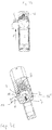
Fig. 3a zeigt eine Seitenansicht einer Pistole 15 mit einem Griffstück 1 und einem Schlitten 16 sowie der anhand derFigs. 1 und2 erläuterten Haltevorrichtung 17. Die Laufmündung (vorne) ist in der Darstellung links, der Schlitten 16 oberhalb des Griffstückes 1. - Die
Fig. 3b zeigt die Ansicht in Richtung des Pfeiles B, das Federplättchen 6 ist aus seiner Ruhelage - Betriebslage - aus dem Griffstück seitlich herausgezogen, sein Vorsprung 10, der dieses Herausziehen erleichtert, ist deutlich zu erkennen, ebenso der auszugseitige Ansatz der schrägen Nutwand 11. - Die
Fig. 3c zeigt den Schnitt C-C derFig. 3a , ebenfalls mit herausgezogenem Federplättchen 6. Die Feder 7, durch die es zum Lauf 8 hin gedrängt wird, ist deutlich erkennbar, ebenso das Halteplättchen 4. Der Schlitz 2, in dem sich die Plättchen und teilweise auch die Feder befinden, weist vom Lauf 8 weg eine Abmessung auf, die das im Folgenden erläuterte Abnehmen des Schlittens 16 erlaubt. - Wenn in der in der
Fig. 3 dargestellten Position zwischen Schlitten und Griffstück das Federplättchen so, wie in derFig. 4 dargestellt, im Uhrzeigersinn verschwenkt wird, indem auf den aus dem Griffstück ragenden Teil des Federplättchens 6 eine Kraft in Richtung des Pfeiles E zum Entriegeln ausgeübt wird, so werden Federplättchen 6 und Halteplättchen 4 gemeinsam gegen die Kraft der Feder 7 um die äußere Kante des Griffstückes im Bereich des Auflagers 13 (Fig. 1 ) verdreht, wodurch der Haltebereich 14 aus der parallel zur Achse 3 verlaufenden Bewegungsbahn des Laufvorsprungs 5 gelangt, Lauf und Schlitten können nach vorne entlang der Führungen 18 zwischen ihnen und dem Griffstück bewegt werden, bis die Position derFig. 4 erreicht ist. - Die
Fig. 4 zeigt, in den gleichen Darstellungen wie dieFig. 3 , die Situation unmittelbar vor dem Abheben des Schlittens nach oben. Es wurden nur die wichtigsten Bezugszeichen eingetragen, zu beachten ist die Verdrehung des Federplättchens 6 gemeinsam mit dem Halteplättchen 4 zufolge des Eingreifens der Hinterschneidungen bzw. Haken der beiden Plättchen. Dadurch wird auch deren gesamte Höhe verringert und erlaubt das Verschwenken um die Außenkante des Haltebereiches 14. In der in derFig. 4 gezeigten Position des Schlittens bezüglich des Griffstückes sind die Führungen 18 zwischen diesen beiden Teilen außer Eingriff gelangt, der Schlitten 16 kann, wie dieFig. 5 zeigt, vom Griffstück 1 abgehoben werden. - Die Erfindung ist nicht auf das dargestellte und beschriebene Beispiel beschränkt, sondern kann verschiedentlich abgewandelt werden. So ist insbesondere eine Anpassung an die eingangs genannten Kippläufe in Kenntnis der Erfindung für den Fachmann kein Problem; die Achse 3 entspricht dann der Lage der Laufachse im schussbereiten Zustand. Die Gründe für die Schräglage des Schlitzes 2 wurden eingangs abgehandelt, es ist selbstverständlich möglich, eine andere Orientierung zu wählen oder den Schlitz in einer Normalebene zur Achse 3 vorzusehen.
- Die Form der Plättchen kann variieren, wesentlich ist nur, dass in der herausgezogenen Lage des Federplättchens ein Verschwenken beider Plättchen sichergestellt wird. Dass, wie im dargestellten Beispiel, im Benutzungsmodus zusätzlich zur Feder 7 eine formschlüssige Sicherung erzielt wird, weil die gesamte Bauhöhe der beiden Plättchen in Wirkrichtung der Feder 7 so groß ist, dass der Laufvorsprung 5 sicher gehalten wird, ist ein Bonus, aber kein Muss.
- Als Material können alle auch bisher im Stand der Technik verwendeten Materialien eingesetzt werden, auch die Herstellung und Bearbeitung stellt in Kenntnis der Erfindung kein Problem dar.
Bezugszeichenliste: 01 Griffstück 11' Schräge Nutfläche 02 Schlitz 12 auszugsfernes Ende 03 Achse 13 Auflager 04 Halteplättchen 14 Haltebereich 05 Laufvorsprung V Pfeil in Richtung nach vorne 06 Federplättchen 15 Pistole 07 Feder 16 Schlitten 08 Lauf 17 Haltevorrichtung 09 Rastfläche(n) 18 Führung(en) 10 Vorsprung E Pfeil in Entriegelungsrichtung 11 Schräge Nutwand
Claims (5)
- Pistole mit einem Griffstück (1) und einem darauf entlang von Führungen (18) beweglichen, einen Lauf (8) aufweisenden, Schlitten (16), mit einer im Griffstück vorgesehenen Sperrvorrichtung für die Vorwärtsbewegung des Laufes (8), die ein in einem Schlitz (2) bewegliches, unter der Wirkung einer Feder (7) stehendes Halteplättchen (4) für einen Laufvorsprung (5) aufweist, dadurch gekennzeichnet, dass im Schlitz (2) zwischen der Feder (7) und dem Halteplättchen (4) ein Federplättchen (6) vorgesehen ist, das quer zur Mittelebene der Pistole teilweise aus dem Schlitz (2) ziehbar ausgebildet ist und in dieser Position mit dem Halteplättchen (4) gegen die Kraft der Feder (7) verschwenkbar ist, wodurch das Halteplättchen (4) aus der Bewegungsbahn des Laufvorsprunges (5) gelangt.
- Pistole nach Anspruch 1, dadurch gekennzeichnet, dass das Halteplättchen (4) im Wesentlichen "A"-förmig und das Federplättchen (6) im Wesentlichen "U"-förmig ausgebildet ist, und dass in der Halteposition die jeweiligen Schenkel einander gegenüberstehen und einander mit Rastflächen (9) kontaktieren.
- Pistole nach Anspruch 2, dadurch gekennzeichnet, dass in der Freigabeposition ein Schenkel des "U" in der Vertiefung des "A" liegt und ein Schenkel des "A" in der Vertiefung des "U".
- Pistole nach Anspruch 2, dadurch gekennzeichnet, dass in der Halteposition die Gesamthöhe der Plättchen (4, 6) größer ist als die Höhe des Schlitzes (2).
- Pistole nach einem der voranstehenden Ansprüche, dadurch gekennzeichnet, dass die beiden Plättchen (4, 6) Hinterschneidungen bzw. Hakenform aufweisen, durch die das Ausmaß des Herausziehens des Federplättchens (6) begrenzt ist.
Priority Applications (4)
| Application Number | Priority Date | Filing Date | Title |
|---|---|---|---|
| EP16155097.5A EP3205971B8 (de) | 2016-02-10 | 2016-02-10 | Pistole |
| ES16155097T ES2712697T3 (es) | 2016-02-10 | 2016-02-10 | Pistola |
| BR102017002236-6A BR102017002236B1 (pt) | 2016-02-10 | 2017-02-02 | Pistola |
| US15/428,888 US9891014B2 (en) | 2016-02-10 | 2017-02-09 | Pistol |
Applications Claiming Priority (1)
| Application Number | Priority Date | Filing Date | Title |
|---|---|---|---|
| EP16155097.5A EP3205971B8 (de) | 2016-02-10 | 2016-02-10 | Pistole |
Publications (3)
| Publication Number | Publication Date |
|---|---|
| EP3205971A1 true EP3205971A1 (de) | 2017-08-16 |
| EP3205971B1 EP3205971B1 (de) | 2018-11-21 |
| EP3205971B8 EP3205971B8 (de) | 2019-03-06 |
Family
ID=55349727
Family Applications (1)
| Application Number | Title | Priority Date | Filing Date |
|---|---|---|---|
| EP16155097.5A Active EP3205971B8 (de) | 2016-02-10 | 2016-02-10 | Pistole |
Country Status (4)
| Country | Link |
|---|---|
| US (1) | US9891014B2 (de) |
| EP (1) | EP3205971B8 (de) |
| BR (1) | BR102017002236B1 (de) |
| ES (1) | ES2712697T3 (de) |
Cited By (2)
| Publication number | Priority date | Publication date | Assignee | Title |
|---|---|---|---|---|
| EP3611458A1 (de) * | 2018-08-17 | 2020-02-19 | SIG SAUER GmbH & Co. KG | Handfeuerwaffe |
| EP4202347A1 (de) | 2021-12-23 | 2023-06-28 | Glock Technology GmbH | Verriegelungsvorrichtung zum verbau in einer griffstückbaugruppe einer handfeuerwaffe |
Families Citing this family (3)
| Publication number | Priority date | Publication date | Assignee | Title |
|---|---|---|---|---|
| EP3367040B1 (de) * | 2017-02-27 | 2019-10-30 | Glock Technology GmbH | Pistole |
| BR102019009671B1 (pt) | 2018-05-15 | 2023-12-26 | Glock Technology Gmbh | Arma de fogo, em particular, pistola, com um dispositivo para desmontagem |
| JP2020106259A (ja) | 2018-12-28 | 2020-07-09 | 有限会社マルゼン | 玩具銃用スライドの着脱装置 |
Citations (3)
| Publication number | Priority date | Publication date | Assignee | Title |
|---|---|---|---|---|
| US2817174A (en) * | 1954-08-17 | 1957-12-24 | High Standard Mfg Corp | Take-down device for firearms |
| US4539889A (en) | 1981-04-30 | 1985-09-10 | Gaston Glock | Automatic pistol with counteracting spring control mechanism |
| DE19507993A1 (de) * | 1995-03-07 | 1996-09-12 | Walther Carl Gmbh | Laufhalterung für Schußwaffen |
Family Cites Families (7)
| Publication number | Priority date | Publication date | Assignee | Title |
|---|---|---|---|---|
| US2107359A (en) * | 1935-05-06 | 1938-02-08 | Mauser Werke Ag | Barrel-holding device for automatic pistols |
| BE789209A (fr) * | 1971-09-24 | 1973-01-15 | Colt Ind Operating Corp | Verrou pour la culasse et mecanisme de demontage pour un pistolet automatique |
| US7823314B1 (en) * | 2008-12-02 | 2010-11-02 | Wheatley Craig A | Firearm with a detachable barrel and suppressed barrel assembly |
| AT510442B1 (de) * | 2011-08-24 | 2012-04-15 | Wilhelm Bubits | Pistole mit verriegelung durch verriegelungskörper |
| WO2013126128A2 (en) * | 2011-12-09 | 2013-08-29 | Sturm, Ruger & Company, Inc. | Slide takedown system and method for firearm |
| DE102013010969B3 (de) * | 2013-07-01 | 2014-10-16 | Heckler & Koch Gmbh | Demontagesicherungsvorrichtung einer Selbstladepistole und Selbstladepistole mit einer Demontagesicherungsvorrichtung |
| ES2711537T3 (es) * | 2016-01-05 | 2019-05-06 | Glock Tech Gmbh | Arma de entrenamiento |
-
2016
- 2016-02-10 ES ES16155097T patent/ES2712697T3/es active Active
- 2016-02-10 EP EP16155097.5A patent/EP3205971B8/de active Active
-
2017
- 2017-02-02 BR BR102017002236-6A patent/BR102017002236B1/pt active IP Right Grant
- 2017-02-09 US US15/428,888 patent/US9891014B2/en active Active
Patent Citations (5)
| Publication number | Priority date | Publication date | Assignee | Title |
|---|---|---|---|---|
| US2817174A (en) * | 1954-08-17 | 1957-12-24 | High Standard Mfg Corp | Take-down device for firearms |
| US4539889A (en) | 1981-04-30 | 1985-09-10 | Gaston Glock | Automatic pistol with counteracting spring control mechanism |
| US4825744A (en) | 1981-04-30 | 1989-05-02 | Gaston Glock | Automatic pistol |
| US4893546A (en) | 1981-04-30 | 1990-01-16 | Gaston Glock | Automatic pistol |
| DE19507993A1 (de) * | 1995-03-07 | 1996-09-12 | Walther Carl Gmbh | Laufhalterung für Schußwaffen |
Cited By (4)
| Publication number | Priority date | Publication date | Assignee | Title |
|---|---|---|---|---|
| EP3611458A1 (de) * | 2018-08-17 | 2020-02-19 | SIG SAUER GmbH & Co. KG | Handfeuerwaffe |
| EP4202347A1 (de) | 2021-12-23 | 2023-06-28 | Glock Technology GmbH | Verriegelungsvorrichtung zum verbau in einer griffstückbaugruppe einer handfeuerwaffe |
| WO2023115093A1 (de) | 2021-12-23 | 2023-06-29 | Glock Technology Gmbh | Verriegelungsvorrichtung zum verbau in einer griffstückbaugruppe einer handfeuerwaffe |
| US12405074B2 (en) | 2021-12-23 | 2025-09-02 | Glock Technology Gmbh | Locking device for installing a handle assembly of a handgun |
Also Published As
| Publication number | Publication date |
|---|---|
| ES2712697T3 (es) | 2019-05-14 |
| EP3205971B8 (de) | 2019-03-06 |
| EP3205971B1 (de) | 2018-11-21 |
| US20170227313A1 (en) | 2017-08-10 |
| BR102017002236B1 (pt) | 2023-10-31 |
| US9891014B2 (en) | 2018-02-13 |
| BR102017002236A2 (pt) | 2017-08-15 |
Similar Documents
| Publication | Publication Date | Title |
|---|---|---|
| EP3205971B1 (de) | Pistole | |
| AT512771B1 (de) | Griffstück für eine Feuerwaffe | |
| DE69105678T2 (de) | Teleskopartige Schiene mit Blockierungsmechanismus. | |
| EP2254442B1 (de) | Feststellvorrichtung zum arretieren eines in oder an einem möbelteil bewegbar gelagerten möbelteils | |
| DE4432192C1 (de) | Stangenmagazin | |
| AT512616A1 (de) | Federbelastete antriebsvorrichtung für ein bewegbares möbelteil | |
| DE3714302A1 (de) | Schere | |
| AT516391A4 (de) | Ausstoßvorrichtung für ein bewegbares Möbelteil | |
| DE112006002236B4 (de) | Behälter mit offenem Ende und Verschlussdeckel | |
| EP2860484A1 (de) | Schlagbolzensicherung für Pistolen | |
| EP2884217B1 (de) | Fangvorrichtung für den Verschluss einer Pistole | |
| DE1557510A1 (de) | Verschluss fuer Armbaender,Halsschmuck od.dgl. | |
| DE3818838A1 (de) | Pistole | |
| DE102011115771A1 (de) | Schließfeder-Vorrichtung für eine Pistole | |
| DE3042658C2 (de) | Schrank mit Schublade | |
| DE45561C (de) | Ladeeinrichtung für Cylinder-Verschlufs-Gewehre mit von unten ansteckbarem Patronen-Magazin | |
| DE1013200B (de) | Pistole fuer Platz- und Zusatzpatronen | |
| DE682485C (de) | Selbstverkaeufer | |
| DE2800987C2 (de) | Verschlußvorrichtung für einen im Waffenkörper vorgesehenen Durchgangsschlitz eines Kammerstengels automatischer Handfeuerwaffen | |
| DE2601000A1 (de) | Durchlaufkanal fuer kommissionier- durchlauflager | |
| DE2534878A1 (de) | Nagelpistole | |
| AT517503B1 (de) | Schnellverschlusssystem für den Einsatz an vorzugsweise Riemen, Gurten, Gürteln od. dgl., mit Magnetkraftunterstützung und Sicherheitsfunktionen gegen unbeabsichtigtes und vorzeitiges Öffnen | |
| DE1482610C3 (de) | Zuführungsrutsche zum selbsttätigen Prüfen und Korrigieren der Orientierung von Verschlußkappen | |
| DE2701454A1 (de) | Blattspender, insbesondere fuer kopiergeraete, und behaelter fuer einen zugehoerigen blattstapel | |
| DE1234953B (de) | Schubladenfuehrung |
Legal Events
| Date | Code | Title | Description |
|---|---|---|---|
| PUAI | Public reference made under article 153(3) epc to a published international application that has entered the european phase |
Free format text: ORIGINAL CODE: 0009012 |
|
| STAA | Information on the status of an ep patent application or granted ep patent |
Free format text: STATUS: THE APPLICATION HAS BEEN PUBLISHED |
|
| AK | Designated contracting states |
Kind code of ref document: A1 Designated state(s): AL AT BE BG CH CY CZ DE DK EE ES FI FR GB GR HR HU IE IS IT LI LT LU LV MC MK MT NL NO PL PT RO RS SE SI SK SM TR |
|
| AX | Request for extension of the european patent |
Extension state: BA ME |
|
| STAA | Information on the status of an ep patent application or granted ep patent |
Free format text: STATUS: REQUEST FOR EXAMINATION WAS MADE |
|
| 17P | Request for examination filed |
Effective date: 20180216 |
|
| RAX | Requested extension states of the european patent have changed |
Extension state: ME Payment date: 20180216 Extension state: BA Payment date: 20180216 |
|
| RBV | Designated contracting states (corrected) |
Designated state(s): AL AT BE BG CH CY CZ DE DK EE ES FI FR GB GR HR HU IE IS IT LI LT LU LV MC MK MT NL NO PL PT RO RS SE SI SK SM TR |
|
| GRAP | Despatch of communication of intention to grant a patent |
Free format text: ORIGINAL CODE: EPIDOSNIGR1 |
|
| STAA | Information on the status of an ep patent application or granted ep patent |
Free format text: STATUS: GRANT OF PATENT IS INTENDED |
|
| RIC1 | Information provided on ipc code assigned before grant |
Ipc: F41A 21/48 20060101ALI20180615BHEP Ipc: F41A 11/00 20060101ALI20180615BHEP Ipc: F41A 3/64 20060101AFI20180615BHEP Ipc: F41A 5/04 20060101ALN20180615BHEP Ipc: F41A 5/06 20060101ALN20180615BHEP |
|
| INTG | Intention to grant announced |
Effective date: 20180705 |
|
| GRAS | Grant fee paid |
Free format text: ORIGINAL CODE: EPIDOSNIGR3 |
|
| GRAA | (expected) grant |
Free format text: ORIGINAL CODE: 0009210 |
|
| STAA | Information on the status of an ep patent application or granted ep patent |
Free format text: STATUS: THE PATENT HAS BEEN GRANTED |
|
| AK | Designated contracting states |
Kind code of ref document: B1 Designated state(s): AL AT BE BG CH CY CZ DE DK EE ES FI FR GB GR HR HU IE IS IT LI LT LU LV MC MK MT NL NO PL PT RO RS SE SI SK SM TR |
|
| AX | Request for extension of the european patent |
Extension state: BA ME |
|
| REG | Reference to a national code |
Ref country code: CH Ref legal event code: EP |
|
| REG | Reference to a national code |
Ref country code: IE Ref legal event code: FG4D Free format text: LANGUAGE OF EP DOCUMENT: GERMAN |
|
| REG | Reference to a national code |
Ref country code: AT Ref legal event code: REF Ref document number: 1068039 Country of ref document: AT Kind code of ref document: T Effective date: 20181215 |
|
| REG | Reference to a national code |
Ref country code: DE Ref legal event code: R096 Ref document number: 502016002537 Country of ref document: DE |
|
| DAX | Request for extension of the european patent (deleted) | ||
| REG | Reference to a national code |
Ref country code: CH Ref legal event code: PK Free format text: BERICHTIGUNG B8 |
|
| REG | Reference to a national code |
Ref country code: NL Ref legal event code: MP Effective date: 20181121 |
|
| PG25 | Lapsed in a contracting state [announced via postgrant information from national office to epo] |
Ref country code: BG Free format text: LAPSE BECAUSE OF FAILURE TO SUBMIT A TRANSLATION OF THE DESCRIPTION OR TO PAY THE FEE WITHIN THE PRESCRIBED TIME-LIMIT Effective date: 20190221 Ref country code: NO Free format text: LAPSE BECAUSE OF FAILURE TO SUBMIT A TRANSLATION OF THE DESCRIPTION OR TO PAY THE FEE WITHIN THE PRESCRIBED TIME-LIMIT Effective date: 20190221 Ref country code: LT Free format text: LAPSE BECAUSE OF FAILURE TO SUBMIT A TRANSLATION OF THE DESCRIPTION OR TO PAY THE FEE WITHIN THE PRESCRIBED TIME-LIMIT Effective date: 20181121 Ref country code: IS Free format text: LAPSE BECAUSE OF FAILURE TO SUBMIT A TRANSLATION OF THE DESCRIPTION OR TO PAY THE FEE WITHIN THE PRESCRIBED TIME-LIMIT Effective date: 20190321 Ref country code: FI Free format text: LAPSE BECAUSE OF FAILURE TO SUBMIT A TRANSLATION OF THE DESCRIPTION OR TO PAY THE FEE WITHIN THE PRESCRIBED TIME-LIMIT Effective date: 20181121 Ref country code: LV Free format text: LAPSE BECAUSE OF FAILURE TO SUBMIT A TRANSLATION OF THE DESCRIPTION OR TO PAY THE FEE WITHIN THE PRESCRIBED TIME-LIMIT Effective date: 20181121 Ref country code: HR Free format text: LAPSE BECAUSE OF FAILURE TO SUBMIT A TRANSLATION OF THE DESCRIPTION OR TO PAY THE FEE WITHIN THE PRESCRIBED TIME-LIMIT Effective date: 20181121 |
|
| REG | Reference to a national code |
Ref country code: ES Ref legal event code: FG2A Ref document number: 2712697 Country of ref document: ES Kind code of ref document: T3 Effective date: 20190514 |
|
| PG25 | Lapsed in a contracting state [announced via postgrant information from national office to epo] |
Ref country code: PT Free format text: LAPSE BECAUSE OF FAILURE TO SUBMIT A TRANSLATION OF THE DESCRIPTION OR TO PAY THE FEE WITHIN THE PRESCRIBED TIME-LIMIT Effective date: 20190321 Ref country code: GR Free format text: LAPSE BECAUSE OF FAILURE TO SUBMIT A TRANSLATION OF THE DESCRIPTION OR TO PAY THE FEE WITHIN THE PRESCRIBED TIME-LIMIT Effective date: 20190222 Ref country code: NL Free format text: LAPSE BECAUSE OF FAILURE TO SUBMIT A TRANSLATION OF THE DESCRIPTION OR TO PAY THE FEE WITHIN THE PRESCRIBED TIME-LIMIT Effective date: 20181121 Ref country code: RS Free format text: LAPSE BECAUSE OF FAILURE TO SUBMIT A TRANSLATION OF THE DESCRIPTION OR TO PAY THE FEE WITHIN THE PRESCRIBED TIME-LIMIT Effective date: 20181121 Ref country code: SE Free format text: LAPSE BECAUSE OF FAILURE TO SUBMIT A TRANSLATION OF THE DESCRIPTION OR TO PAY THE FEE WITHIN THE PRESCRIBED TIME-LIMIT Effective date: 20181121 Ref country code: AL Free format text: LAPSE BECAUSE OF FAILURE TO SUBMIT A TRANSLATION OF THE DESCRIPTION OR TO PAY THE FEE WITHIN THE PRESCRIBED TIME-LIMIT Effective date: 20181121 |
|
| PG25 | Lapsed in a contracting state [announced via postgrant information from national office to epo] |
Ref country code: CZ Free format text: LAPSE BECAUSE OF FAILURE TO SUBMIT A TRANSLATION OF THE DESCRIPTION OR TO PAY THE FEE WITHIN THE PRESCRIBED TIME-LIMIT Effective date: 20181121 Ref country code: DK Free format text: LAPSE BECAUSE OF FAILURE TO SUBMIT A TRANSLATION OF THE DESCRIPTION OR TO PAY THE FEE WITHIN THE PRESCRIBED TIME-LIMIT Effective date: 20181121 Ref country code: PL Free format text: LAPSE BECAUSE OF FAILURE TO SUBMIT A TRANSLATION OF THE DESCRIPTION OR TO PAY THE FEE WITHIN THE PRESCRIBED TIME-LIMIT Effective date: 20181121 |
|
| REG | Reference to a national code |
Ref country code: DE Ref legal event code: R097 Ref document number: 502016002537 Country of ref document: DE |
|
| PG25 | Lapsed in a contracting state [announced via postgrant information from national office to epo] |
Ref country code: SK Free format text: LAPSE BECAUSE OF FAILURE TO SUBMIT A TRANSLATION OF THE DESCRIPTION OR TO PAY THE FEE WITHIN THE PRESCRIBED TIME-LIMIT Effective date: 20181121 Ref country code: RO Free format text: LAPSE BECAUSE OF FAILURE TO SUBMIT A TRANSLATION OF THE DESCRIPTION OR TO PAY THE FEE WITHIN THE PRESCRIBED TIME-LIMIT Effective date: 20181121 Ref country code: EE Free format text: LAPSE BECAUSE OF FAILURE TO SUBMIT A TRANSLATION OF THE DESCRIPTION OR TO PAY THE FEE WITHIN THE PRESCRIBED TIME-LIMIT Effective date: 20181121 Ref country code: SM Free format text: LAPSE BECAUSE OF FAILURE TO SUBMIT A TRANSLATION OF THE DESCRIPTION OR TO PAY THE FEE WITHIN THE PRESCRIBED TIME-LIMIT Effective date: 20181121 |
|
| PLBE | No opposition filed within time limit |
Free format text: ORIGINAL CODE: 0009261 |
|
| STAA | Information on the status of an ep patent application or granted ep patent |
Free format text: STATUS: NO OPPOSITION FILED WITHIN TIME LIMIT |
|
| REG | Reference to a national code |
Ref country code: CH Ref legal event code: PL |
|
| 26N | No opposition filed |
Effective date: 20190822 |
|
| PG25 | Lapsed in a contracting state [announced via postgrant information from national office to epo] |
Ref country code: MC Free format text: LAPSE BECAUSE OF FAILURE TO SUBMIT A TRANSLATION OF THE DESCRIPTION OR TO PAY THE FEE WITHIN THE PRESCRIBED TIME-LIMIT Effective date: 20181121 Ref country code: SI Free format text: LAPSE BECAUSE OF FAILURE TO SUBMIT A TRANSLATION OF THE DESCRIPTION OR TO PAY THE FEE WITHIN THE PRESCRIBED TIME-LIMIT Effective date: 20181121 Ref country code: LU Free format text: LAPSE BECAUSE OF NON-PAYMENT OF DUE FEES Effective date: 20190210 |
|
| REG | Reference to a national code |
Ref country code: IE Ref legal event code: MM4A |
|
| PG25 | Lapsed in a contracting state [announced via postgrant information from national office to epo] |
Ref country code: CH Free format text: LAPSE BECAUSE OF NON-PAYMENT OF DUE FEES Effective date: 20190228 Ref country code: LI Free format text: LAPSE BECAUSE OF NON-PAYMENT OF DUE FEES Effective date: 20190228 |
|
| PG25 | Lapsed in a contracting state [announced via postgrant information from national office to epo] |
Ref country code: IE Free format text: LAPSE BECAUSE OF NON-PAYMENT OF DUE FEES Effective date: 20190210 |
|
| PG25 | Lapsed in a contracting state [announced via postgrant information from national office to epo] |
Ref country code: TR Free format text: LAPSE BECAUSE OF FAILURE TO SUBMIT A TRANSLATION OF THE DESCRIPTION OR TO PAY THE FEE WITHIN THE PRESCRIBED TIME-LIMIT Effective date: 20181121 |
|
| PG25 | Lapsed in a contracting state [announced via postgrant information from national office to epo] |
Ref country code: MT Free format text: LAPSE BECAUSE OF FAILURE TO SUBMIT A TRANSLATION OF THE DESCRIPTION OR TO PAY THE FEE WITHIN THE PRESCRIBED TIME-LIMIT Effective date: 20181121 |
|
| GBPC | Gb: european patent ceased through non-payment of renewal fee |
Effective date: 20200210 |
|
| PG25 | Lapsed in a contracting state [announced via postgrant information from national office to epo] |
Ref country code: GB Free format text: LAPSE BECAUSE OF NON-PAYMENT OF DUE FEES Effective date: 20200210 |
|
| PG25 | Lapsed in a contracting state [announced via postgrant information from national office to epo] |
Ref country code: CY Free format text: LAPSE BECAUSE OF FAILURE TO SUBMIT A TRANSLATION OF THE DESCRIPTION OR TO PAY THE FEE WITHIN THE PRESCRIBED TIME-LIMIT Effective date: 20181121 |
|
| PG25 | Lapsed in a contracting state [announced via postgrant information from national office to epo] |
Ref country code: HU Free format text: LAPSE BECAUSE OF FAILURE TO SUBMIT A TRANSLATION OF THE DESCRIPTION OR TO PAY THE FEE WITHIN THE PRESCRIBED TIME-LIMIT; INVALID AB INITIO Effective date: 20160210 |
|
| PG25 | Lapsed in a contracting state [announced via postgrant information from national office to epo] |
Ref country code: MK Free format text: LAPSE BECAUSE OF FAILURE TO SUBMIT A TRANSLATION OF THE DESCRIPTION OR TO PAY THE FEE WITHIN THE PRESCRIBED TIME-LIMIT Effective date: 20181121 |
|
| P01 | Opt-out of the competence of the unified patent court (upc) registered |
Effective date: 20230601 |
|
| PGFP | Annual fee paid to national office [announced via postgrant information from national office to epo] |
Ref country code: ES Payment date: 20260305 Year of fee payment: 11 |
|
| PGFP | Annual fee paid to national office [announced via postgrant information from national office to epo] |
Ref country code: DE Payment date: 20260128 Year of fee payment: 11 |
|
| PGFP | Annual fee paid to national office [announced via postgrant information from national office to epo] |
Ref country code: AT Payment date: 20260217 Year of fee payment: 11 |
|
| PGFP | Annual fee paid to national office [announced via postgrant information from national office to epo] |
Ref country code: BE Payment date: 20260128 Year of fee payment: 11 Ref country code: IT Payment date: 20260129 Year of fee payment: 11 |
|
| PGFP | Annual fee paid to national office [announced via postgrant information from national office to epo] |
Ref country code: FR Payment date: 20260127 Year of fee payment: 11 |