EP3204973B1 - Impurity containing cathode material with preferred morphology and method to prepare from impurity containing metal carbonate - Google Patents
Impurity containing cathode material with preferred morphology and method to prepare from impurity containing metal carbonate Download PDFInfo
- Publication number
- EP3204973B1 EP3204973B1 EP15849645.5A EP15849645A EP3204973B1 EP 3204973 B1 EP3204973 B1 EP 3204973B1 EP 15849645 A EP15849645 A EP 15849645A EP 3204973 B1 EP3204973 B1 EP 3204973B1
- Authority
- EP
- European Patent Office
- Prior art keywords
- sodium
- sulfur
- mco
- carbonate
- ratio
- Prior art date
- Legal status (The legal status is an assumption and is not a legal conclusion. Google has not performed a legal analysis and makes no representation as to the accuracy of the status listed.)
- Active
Links
Images


Classifications
-
- C—CHEMISTRY; METALLURGY
- C01—INORGANIC CHEMISTRY
- C01G—COMPOUNDS CONTAINING METALS NOT COVERED BY SUBCLASSES C01D OR C01F
- C01G53/00—Compounds of nickel
- C01G53/80—Compounds containing nickel, with or without oxygen or hydrogen, and containing one or more other elements
- C01G53/82—Compounds containing nickel, with or without oxygen or hydrogen, and containing two or more other elements
-
- C—CHEMISTRY; METALLURGY
- C01—INORGANIC CHEMISTRY
- C01G—COMPOUNDS CONTAINING METALS NOT COVERED BY SUBCLASSES C01D OR C01F
- C01G53/00—Compounds of nickel
- C01G53/06—Carbonates
-
- C—CHEMISTRY; METALLURGY
- C01—INORGANIC CHEMISTRY
- C01G—COMPOUNDS CONTAINING METALS NOT COVERED BY SUBCLASSES C01D OR C01F
- C01G53/00—Compounds of nickel
- C01G53/40—Complex oxides containing nickel and at least one other metal element
- C01G53/42—Complex oxides containing nickel and at least one other metal element containing alkali metals, e.g. LiNiO2
- C01G53/44—Complex oxides containing nickel and at least one other metal element containing alkali metals, e.g. LiNiO2 containing manganese
- C01G53/50—Complex oxides containing nickel and at least one other metal element containing alkali metals, e.g. LiNiO2 containing manganese of the type (MnO2)n-, e.g. Li(NixMn1-x)O2 or Li(MyNixMn1-x-y)O2
-
- H—ELECTRICITY
- H01—ELECTRIC ELEMENTS
- H01M—PROCESSES OR MEANS, e.g. BATTERIES, FOR THE DIRECT CONVERSION OF CHEMICAL ENERGY INTO ELECTRICAL ENERGY
- H01M10/00—Secondary cells; Manufacture thereof
- H01M10/05—Accumulators with non-aqueous electrolyte
- H01M10/052—Li-accumulators
-
- H—ELECTRICITY
- H01—ELECTRIC ELEMENTS
- H01M—PROCESSES OR MEANS, e.g. BATTERIES, FOR THE DIRECT CONVERSION OF CHEMICAL ENERGY INTO ELECTRICAL ENERGY
- H01M10/00—Secondary cells; Manufacture thereof
- H01M10/05—Accumulators with non-aqueous electrolyte
- H01M10/052—Li-accumulators
- H01M10/0525—Rocking-chair batteries, i.e. batteries with lithium insertion or intercalation in both electrodes; Lithium-ion batteries
-
- H—ELECTRICITY
- H01—ELECTRIC ELEMENTS
- H01M—PROCESSES OR MEANS, e.g. BATTERIES, FOR THE DIRECT CONVERSION OF CHEMICAL ENERGY INTO ELECTRICAL ENERGY
- H01M4/00—Electrodes
- H01M4/02—Electrodes composed of, or comprising, active material
- H01M4/36—Selection of substances as active materials, active masses, active liquids
- H01M4/48—Selection of substances as active materials, active masses, active liquids of inorganic oxides or hydroxides
- H01M4/50—Selection of substances as active materials, active masses, active liquids of inorganic oxides or hydroxides of manganese
- H01M4/505—Selection of substances as active materials, active masses, active liquids of inorganic oxides or hydroxides of manganese of mixed oxides or hydroxides containing manganese for inserting or intercalating light metals, e.g. LiMn2O4 or LiMn2OxFy
-
- H—ELECTRICITY
- H01—ELECTRIC ELEMENTS
- H01M—PROCESSES OR MEANS, e.g. BATTERIES, FOR THE DIRECT CONVERSION OF CHEMICAL ENERGY INTO ELECTRICAL ENERGY
- H01M4/00—Electrodes
- H01M4/02—Electrodes composed of, or comprising, active material
- H01M4/36—Selection of substances as active materials, active masses, active liquids
- H01M4/48—Selection of substances as active materials, active masses, active liquids of inorganic oxides or hydroxides
- H01M4/52—Selection of substances as active materials, active masses, active liquids of inorganic oxides or hydroxides of nickel, cobalt or iron
- H01M4/525—Selection of substances as active materials, active masses, active liquids of inorganic oxides or hydroxides of nickel, cobalt or iron of mixed oxides or hydroxides containing iron, cobalt or nickel for inserting or intercalating light metals, e.g. LiNiO2, LiCoO2 or LiCoOxFy
-
- C—CHEMISTRY; METALLURGY
- C01—INORGANIC CHEMISTRY
- C01P—INDEXING SCHEME RELATING TO STRUCTURAL AND PHYSICAL ASPECTS OF SOLID INORGANIC COMPOUNDS
- C01P2002/00—Crystal-structural characteristics
- C01P2002/50—Solid solutions
-
- C—CHEMISTRY; METALLURGY
- C01—INORGANIC CHEMISTRY
- C01P—INDEXING SCHEME RELATING TO STRUCTURAL AND PHYSICAL ASPECTS OF SOLID INORGANIC COMPOUNDS
- C01P2002/00—Crystal-structural characteristics
- C01P2002/70—Crystal-structural characteristics defined by measured X-ray, neutron or electron diffraction data
- C01P2002/72—Crystal-structural characteristics defined by measured X-ray, neutron or electron diffraction data by d-values or two theta-values, e.g. as X-ray diagram
-
- C—CHEMISTRY; METALLURGY
- C01—INORGANIC CHEMISTRY
- C01P—INDEXING SCHEME RELATING TO STRUCTURAL AND PHYSICAL ASPECTS OF SOLID INORGANIC COMPOUNDS
- C01P2004/00—Particle morphology
- C01P2004/01—Particle morphology depicted by an image
- C01P2004/03—Particle morphology depicted by an image obtained by SEM
-
- C—CHEMISTRY; METALLURGY
- C01—INORGANIC CHEMISTRY
- C01P—INDEXING SCHEME RELATING TO STRUCTURAL AND PHYSICAL ASPECTS OF SOLID INORGANIC COMPOUNDS
- C01P2004/00—Particle morphology
- C01P2004/51—Particles with a specific particle size distribution
-
- C—CHEMISTRY; METALLURGY
- C01—INORGANIC CHEMISTRY
- C01P—INDEXING SCHEME RELATING TO STRUCTURAL AND PHYSICAL ASPECTS OF SOLID INORGANIC COMPOUNDS
- C01P2004/00—Particle morphology
- C01P2004/60—Particles characterised by their size
- C01P2004/61—Micrometer sized, i.e. from 1-100 micrometer
-
- C—CHEMISTRY; METALLURGY
- C01—INORGANIC CHEMISTRY
- C01P—INDEXING SCHEME RELATING TO STRUCTURAL AND PHYSICAL ASPECTS OF SOLID INORGANIC COMPOUNDS
- C01P2004/00—Particle morphology
- C01P2004/80—Particles consisting of a mixture of two or more inorganic phases
-
- C—CHEMISTRY; METALLURGY
- C01—INORGANIC CHEMISTRY
- C01P—INDEXING SCHEME RELATING TO STRUCTURAL AND PHYSICAL ASPECTS OF SOLID INORGANIC COMPOUNDS
- C01P2006/00—Physical properties of inorganic compounds
- C01P2006/11—Powder tap density
-
- C—CHEMISTRY; METALLURGY
- C01—INORGANIC CHEMISTRY
- C01P—INDEXING SCHEME RELATING TO STRUCTURAL AND PHYSICAL ASPECTS OF SOLID INORGANIC COMPOUNDS
- C01P2006/00—Physical properties of inorganic compounds
- C01P2006/12—Surface area
-
- C—CHEMISTRY; METALLURGY
- C01—INORGANIC CHEMISTRY
- C01P—INDEXING SCHEME RELATING TO STRUCTURAL AND PHYSICAL ASPECTS OF SOLID INORGANIC COMPOUNDS
- C01P2006/00—Physical properties of inorganic compounds
- C01P2006/40—Electric properties
-
- C—CHEMISTRY; METALLURGY
- C01—INORGANIC CHEMISTRY
- C01P—INDEXING SCHEME RELATING TO STRUCTURAL AND PHYSICAL ASPECTS OF SOLID INORGANIC COMPOUNDS
- C01P2006/00—Physical properties of inorganic compounds
- C01P2006/80—Compositional purity
-
- H—ELECTRICITY
- H01—ELECTRIC ELEMENTS
- H01M—PROCESSES OR MEANS, e.g. BATTERIES, FOR THE DIRECT CONVERSION OF CHEMICAL ENERGY INTO ELECTRICAL ENERGY
- H01M4/00—Electrodes
- H01M4/02—Electrodes composed of, or comprising, active material
- H01M2004/026—Electrodes composed of, or comprising, active material characterised by the polarity
- H01M2004/028—Positive electrodes
-
- Y—GENERAL TAGGING OF NEW TECHNOLOGICAL DEVELOPMENTS; GENERAL TAGGING OF CROSS-SECTIONAL TECHNOLOGIES SPANNING OVER SEVERAL SECTIONS OF THE IPC; TECHNICAL SUBJECTS COVERED BY FORMER USPC CROSS-REFERENCE ART COLLECTIONS [XRACs] AND DIGESTS
- Y02—TECHNOLOGIES OR APPLICATIONS FOR MITIGATION OR ADAPTATION AGAINST CLIMATE CHANGE
- Y02E—REDUCTION OF GREENHOUSE GAS [GHG] EMISSIONS, RELATED TO ENERGY GENERATION, TRANSMISSION OR DISTRIBUTION
- Y02E60/00—Enabling technologies; Technologies with a potential or indirect contribution to GHG emissions mitigation
- Y02E60/10—Energy storage using batteries
Definitions
- This invention relates to a precursor for cathode materials for rechargeable lithium batteries and a process to produce these precursors.
- the cathode materials are so-called NMC cathode materials, where NMC stands for nickel-manganese-cobalt. More particularly, this invention focuses on supplying precursors for NMC cathode materials with the aim that the final NMC cathode materials have a large surface area and therefore are particularly suitable for power demanding applications like batteries for hybrid electric vehicles.
- NMC cathode materials are generally prepared by solid state reactions, wherein a source of lithium - for example Li 2 CO 3 - is blended with a Ni-Mn-Co containing precursor, and the mixture is fired in an oxygen containing atmosphere - for example air - to yield the final lithium transition metal oxide powder.
- a source of lithium - for example Li 2 CO 3 -
- Ni-Mn-Co containing precursor for example Li 2 CO 3
- oxygen containing atmosphere - for example air - oxygen containing atmosphere
- NMC has roughly the stoichiometry LiMO 2 , where M is a transition metal mostly consisting of Ni, Mn and Co.
- the crystal structure is an ordered rocksalt structure where the cations order into 2-dimensional Li and M layers.
- the spacegroup is R-3M.
- One effect of increasing the Li:M stoichiometric ratio is that the cation mixing is changed.
- NMC is a "mixed metal" cathode material, and it is known that NMC cannot be prepared from “non-mixed” precursors.
- the use of non-mixed precursors - for example NiO + Mn 2 CO 3 + Co 3 O 4 - generally results in a poor performance electrode material.
- the Ni, Mn, Co cations need to be well mixed at atomic scale. In the standard process, this is achieved by using mixed transition metal precursors, where the transition metal atoms are well mixed at nanometer scale.
- a mixed metal hydroxide M(OH) 2 or its oxidized form MOOH, is used as precursor.
- Mixed hydroxide precursors are usually prepared by a precipitation process.
- a process which is widely used industrially, comprises a step where a flow of (a) a metal sulfate solution, (b) a NaOH solution and (c) a NH 4 OH solution are fed into a reactor.
- the resulting hydroxide contains sulfur, but is practically free of sodium. Most of the sulfur remains during the firing of the precursor and hence the final commercial NMC cathode contains sulfur.
- the standard precipitation process to prepare mixed hydroxide precursors involves the use of ammonia.
- the ammonia is a so-called chelating agent.
- the Ni-ammonia complexes increase the metal solubility and thus decrease the nucleation rate during precipitation.
- ammonia for example, it would be difficult to prepare a sufficiently dense hydroxide, especially if large particles having sizes > 10 ⁇ m are desired. Without ammonia, it is practically impossible to stabilize transition metal hydroxide precipitation conditions in a way, which yields large particles having the preferred spherical morphology.
- the ammonia that is present in a precipitation process always creates a certain safety risk. In the case of an accident, hazardous fumes evolve, so it would - from a safety point of view - be highly desirable to develop an ammonia free precipitation process. After precipitation, the ammonia remains in the filter solution. As the ammonia cannot be released to the environment, the waste water is treated to remove - preferably to recycle - the ammonia.
- ammonia installations are expensive and increase the capital investment significantly, as well as the operating cost for the waste treatment, in particular by the higher need of energy. It would therefore be desired to develop an ammonia free precipitation method, which supplies mixed precursor having a sufficient density and spherical morphology, for reasons described below.
- US7897069 discloses a mixed metal carbonate precursor to prepare NMC.
- the particle size is 5 - 20 ⁇ m and the BET (Brunauer-Emmett-Teller) surface area is 40 - 80 m 2 /g.
- the tap density is above 1.7 g/cm 3 .
- the preparation is a co-precipitation of a dissolved transition metal salt with a carbonate or bicarbonate solution.
- the precipitation occurs at a CO 3 / M ratio of 2 - 7, preferably 3 - 6.
- the method of the patent uses an excess of carbonate (CO 3 ) in the reaction solution and enables to achieve a composite carbonate with a high yield.
- bi-carbonate precipitation It is relatively easy to achieve a mixed carbonate precursor with desired properties like spherical morphology, good density etc. by the following bicarbonate process reaction: 2NaHCO 3 + MSO 4 ⁇ Na 2 SO 4 + MCO 3 + H 2 CO 3 . (1)
- bi-carbonate precipitation happens at lower pH in the presence of a high concentration of carbonate.
- the lower pH tends to suppress Na insertion and the excess CO 3 tends to suppress sulfur insertion into the mixed transition metal carbonate crystal structure.
- bicarbonate can allow to precipitate relatively poor transition metal carbonate.
- a major rate performance limitation is the solid state diffusion rate of lithium within a single particle. Generally the typical time for diffusion can be reduced - and thus a higher power can be achieved - if the solid state diffusion length decreases. The diffusion length can be decreased by reducing the particle size, but there are limitations since small particles have a low density. Such a low density is not desired because it causes problems during electrode coating, and the volumetric energy density of the final battery is low. Much more preferred are relatively large, spherical and relatively dense particles which have an open, interconnected porosity.
- NMC with preferred morphology an interconnected meso or nano porosity
- the open, interconnected porosity contributes to the surface so "NMC with preferred morphology” has a much higher BET surface area than expected from dense particles having the same shape. So the BET surface area of commercial NMC consisting of dense particles is typically in the order of 0.2 to 0.4 m 2 /g.
- the NMC with preferred morphology typically may have a BET surface area in the range of 1 m 2 /g or higher.
- the pores of NMC with preferred morphology will be filled with electrolyte, which acts as a diffusion highway into the particle because liquid diffusion is much faster than the diffusion in solid particles.
- electrolyte acts as a diffusion highway into the particle because liquid diffusion is much faster than the diffusion in solid particles.
- the present invention aims at providing NMC cathode materials and carbonate based precursors for those NMC cathode materials, the NMC cathode material being particularly suitable for use in automotive applications.
- the invention can provide a carbonate precursor compound for manufacturing a lithium metal (M)-oxide powder usable as an active positive electrode material in lithium-ion batteries, M comprising 20 to 90 mol% Ni, 10 to 70 mol% Mn and 10 to 40 mol% Co, the precursor further comprising a sodium and sulfur impurity, wherein the sodium to sulfur molar ratio (Na/S) is 0.4 ⁇ Na/S ⁇ 2.
- the dopant A may be either one or more of Mg, Al, Ti, Zr, Ca, Ce, Cr, Nb, Sn, Zn and B.
- the sum (2* Na w t)+ S w t of the sodium (Na w t) and sulfur (S w t) content expressed in wt% may be more than 0.4 wt% and less than 1.6 wt%.
- the sodium content may be between 0.1 and 0.7 wt%, and the sulfur content between 0.2 and 0.9 wt%.
- the sodium content may be between 0.15 and 0.30 wt%, and the sulfur content between 0.20 and 0.45 wt%.
- the carbonate precursor compound may have a particle size distribution with 10 ⁇ m ⁇ D50 ⁇ 20 ⁇ m.
- the first aspect of the invention is to provide a mixed metal carbonate precursor for NMC cathode materials.
- the NMC cathode materials After firing, the NMC cathode materials have a preferred morphology.
- the obtained cathodes have an open porosity and the BET surface area is significantly higher than expected for dense particles of the same size that are not prepared according to the invention.
- the preferred morphology supports high power, which makes the NMC cathode suitable for automotive applications.
- the precursor contains sodium and sulfur impurities, the concentration and ratio of these impurities is well designed to achieve an excellent performance. It is clear that further precursor embodiments according to the invention may be provided by combining features that are covered in each of the different precursor embodiments described before.
- the lithium metal oxide powder comprises a secondary LiNaSO 4 phase.
- the relative weight of the secondary LiNaSO 4 phase is at least 0.5 wt%, as determined by Rietveld analysis of the XRD pattern of the powder. It is preferred that the relative weight is at least 1.5 wt%, or even at least 3.5 wt%.
- the dopant A may be either one or more of Mg, Al, Ti, Zr, Ca, Ce, Cr, Nb, Sn, Zn and B.
- lithium metal oxide powder according to the invention it may be that, either
- the second aspect of the invention Is a cathode material prepared from the mixed metal carbonate.
- the cathode material has a preferred morphology. Particles are generally spherical, have an open porosity and the surface area is significantly larger than that of a cathode material consisting of dense particles of the similar shape. It is clear that further lithium metal oxide powder embodiments according to the invention may be provided by combining features that are covered in each of the different powder embodiments described before.
- the invention can provide a method for preparing a carbonate precursor compound, comprising the steps of:
- a and A' are either one or more of Mg, Al, Ti, Zr, Ca, Ce, Cr, Nb, Sn, Zn and B.
- the concentration of NH 3 in the reactor may be less than 5.0 g/L, or the reactive liquid mixture may be basically free of NH 3 .
- the reactor may be a continuous stirred tank reactor (CSTR).
- the ionic solution further comprises either one or both of a hydroxide and a bicarbonate solution, and the ratio OH/CO 3 , or OH/HCO 3 , or both these ratios are less than 1/10.
- the third aspect of the invention is a cheap process to prepare these mixed carbonate precursors by a continuous precipitation process.
- Feeds of dissolved Na 2 CO 3 and metal sulfate are fed to reactor.
- the base: acid flow rate ratio (Na 2 CO 3 : MSO 4 ) is controlled to obtain a mixed metal carbonate having a desired Na and S impurity concentration ratio. Growth of particles is not controlled by controlling the flow rate ratio but by addition of seeds to the reactor.
- the invention can provide a method for preparing the lithium metal oxide powder according to the second aspect of the invention, comprising the steps of:
- a possible reaction formula is A Na 2 CO 3 + B MSO 4 ⁇ Na 2 SO 4 + M 1 ⁇ 2 x Na 2 x CO 3 1 ⁇ y SO 4 y
- a and B are near to 1, x and y are small numbers, typically less than 0.05.
- the desired Na/S ratio in metal carbonate precursors is between 0.4 and 2, or 0.4 ⁇ Na/S ⁇ 2.
- the final cathode contains a LiNaSO 4 secondary phase. If the sodium to sulfur ratio is near to unity then the content of LiNaSO 4 is maximized. In this case LiNaSO 4 can be detected by XRD diffraction, especially when applying slow scans to achieve high counts. If the sodium to sulfur ratio increases or decreases then - the more it deviates from unity - less LiNaSO 4 is present and the detection by XRD becomes difficult; though LiNaSO 4 is still present
- the current patent application aims at supplying a precursor which contains both sodium and sulfur, and where the sodium and sulfur contents are optimized in a way that the final NMC cathode may contain crystalline LINaSO 4 , that means the sodium impurity is present as soluble salt, and for that reason has an excellent electrochemical performance.
- LiNaSO 4 typically originates from impurities in the carbonate precursor. It might be that a mixed metal carbonate precursors with the right sodium to sulfur ratio is not available but instead of this a carbonate precursor with to large Na: sulfur ration is available. In this special case, the desired sodium to sulfur ratio in the final cathode can still be achieved by adding a source of sulfur.
- the sulfur is added before firing, for example In the form of Li 2 SO 4 -
- a typical reaction is Li 2 SO 4 + Na ⁇ LiNaSO 4 + Li.
- the Na is extracted from the lithium transition metal oxide and the lithium is inserted into the lithium transition metal oxide crystal structure.
- a typical metal hydroxide precipitation is a continuous process approaching a steady state.
- a continuous flow reactor is used wherein flows of dissolved base (for example NaOH) and dissolved acid (for example MSO 4 ) are continuously fed into the stirred reactor.
- the particle size control is typically achieved by a variation of the flow ratios.
- Within a narrow range small changes of flow ratio between NaOH (base) and MSO 4 (acid) allow to achieve different particle sizes.
- Mixed metal carbonate is prepared by a co-precipitation reaction.
- a flow of dissolved Na 2 CO 3 and at least one flow of dissolved metal sulfate are fed Into a reactor under strong agitation.
- the metal flow typically is a mixture of different transition metal sulfates.
- metal sulfates can be fed by several separated feeds.
- the agitation is achieved by a rotating impellor but other solutions - like circulating flows are also possible.
- the precipitation reaction preferably Is a continuous precipitation where feeds are Inserted to a reactor which has an overflow and product is continuously discharged from the reactor.
- the precipitation reaction can also be performed In a batch process.
- the basic flows of sodium carbonate and metal sulfate further flows can be added like metal chlorides sodium bicarbonate, ammonium carbonate etc.
- the current invention supplies a solution to this problem, and the Na 2 CO 3 / MSO 4 ratio is kept at a ratio which results in a preferred Na/S ratio.
- the precipitate is separated from the liquid by a suitable separation technique such as filtering.
- a suitable separation technique such as filtering.
- an ion exchange operation for example washing with a caustic NaOH solution
- washing with caustic solution can adjust the sodium and sulfur content.
- a caustic wash by exposing the impurity containing carbonate to a diluted base like NaOH, is suitable to reduce the sulfur impurity content.
- the filtering or caustic wash is typically followed by a washing process using water. Careful washing can remove a fraction of the present impurities.
- the carbonate precursor is dried at a typical drying temperature below 400°C. Alternatively, the carbonate can be roasted at a higher temperature.
- the mixed metal carbonate is then mixed with a Li-source - for example Li 2 CO 3 followed by firing in oxygen containing atmosphere. Because of the simultaneous presence of Li Na and sulfur after-after sintering - LiNaSO 4 is present in the lithium transition metal.
- the resulting product is a sodium and sulfur containing transition metal carbonate which is especially suitable as precursor for lithium transition metal cathode materials.
- Li 2 CO 3 could also be added to the washed (moist) filter cake, followed by drying or prefiring.
- the final cathode material has a preferred morphology.
- Particles have spherical shape and exhibit an open porosity.
- the BET surface area is larger than that of similar shaped but dense particles.
- the open porosity is tightly related to the use of mixed metal carbonate precursors.
- the open porosity remains in the final cathode product. It is relatively easy to achieve the open porosity if the cathode material is prepared at small scale. If however the cathode material is fired in an industrial way, for example using trays where several kg of precursor blends are fired in one tray, then the open porosity is more difficult to achieve. The authors observed that it is very important to heat the blend slowly. It is particularly important that the tray is not heated fast at a temperature range between 300 and 500°C. A suitable temperature profile needs at least 2hr to increase the temperature from 300 to 500°C.
- a carbonate precursor is provided that allows the preparation of NMC cathode powders with higher surface area and open porosity, making the obtained NMC cathodes especially suitable for high power applications.
- the BET surface area is an important tool to estimate the open porosity. If particles are dense, the surface area is low, hence, if the surface area is significantly larger than expected for particles of a given size, then an open porosity is likely to be present. Many variations from the proposed process are possible.
- Example 1 Precipitation of a Na and Sulfur containing carbonate
- a first series of precipitations with varying acid to base flow rate ratios (7 samples) is performed as follows:
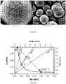
- the final sample is analyzed by XRD, BET surface area, tap density measurement, FESEM, ICP (of the elements Ni, Mn, Co, Na, S). Table 1 shows the results obtained for the final sample.
- Table 1 as well as Figure 1 show the results for sodium and sulfur of the ICP analysis. Obviously a purely metal carbonate does not precipitate, and in all cases a relatively large impurity of sulfate and/or sodium is present. The sodium and sulfur was not removed by the washing. Many ion exchange attempts were undertaken but especially the removal of the sodium impurity is difficult.
- Figure 1 shows a region where 1 ⁇ Na/S ⁇ 2.
- Preferred precursors are within the narrow region of 0.4 to 2.0.
- the final sample is analyzed by XRD, BET surface area, tap density measurement, FESEM, ICP (of the elements Ni, Mn, Co, Na, S).
- Table 1.2 shows the obtained results for the final sample.
- Table 2 as well as Figure 3 show the ICP analysis results for sodium and sulfur.
- Example 1 the carbonates with different metal compositions follow the trend shown in Example 1 for 552 (also shown on Figure 2 ). Only a few exceptions (Ni free compounds precipitated with a low base/acid (CO 3 /M) flow rate ratio) have lower impurities. These Ni free compounds are not of interest as a precursor for NMC. The dotted line is a guide for the eye to locate typical impurities. By a suitable variation of flow rate ratio these impurities can be tuned so that the metal carbonate has a composition within the preferred region 1 ⁇ Na/S ⁇ 2, respectively 0.4 ⁇ Na/S ⁇ 1.
- the precipitation conditions are varied to investigate possibilities to derivate from the general trend for Na and S impurities as a function of CO 3 / M flow ratio.
- 10% of the Na 2 CO 3 is replaced by 2NaHCO 3 (in this case the Na concentration is fixed at 4 mol / L; the flow rate ratio is defined as 0.5*Na / SO 4 ).
- 10 % of the Na 2 CO 3 is replaced by NaOH (2 mol NaOH per 1 mol Na 2 CO 3 ).
- the precipitation temperature is changed (to 25°C)
- the concentrations of the reactants are changed, in some cases seeding technology is applied, in some cases the geometry of the reactor is changed, in some cases the residence time is changed.
- Figure 5 summarizes the results.
- Example 4 Impossibility of conventional PSD control for sodium and sulfur containing transition metal carbonates
- a preferred precipitation process is a continuous process (also known as continuous flow reactor).
- Figure 6 shows the design of a continuous stirred tank reactor (CSTR), with the following references: 1 Water jacket 2 Overflow 3 Dosing tube 4 Motor 5 Impeller 6 pH senor 7 Baffle 8 Temperature sensor 9 Outlet valve
- a typical precipitation process for mixed hydroxides is a continuous precipitation where the particle size is adjusted by carefully controlling the flow rate (acid to base) ratios. This approach is based on the fact that for a certain flow rate ratio a distinct steady state particle size is obtained. Therefore, if the base/acid ratio increases, typically the PSD of the precipitate during steady state decreases, so small variations of the acid to base flow rate ratio are utilized to control the particle size in a narrow desired range.
- the underlying scientific reason is the dependence of nucleation rate on pH. As the pH increases the nucleation rate increases and the particle size decreases. This example will show that such a process is virtually impossible for sodium and sulfur containing mixed carbonate.
- the flow rate ratio is determined by the need to achieve a desired sodium to sulfur ratio, it is adjusted in that sense. Therefore the PSD cannot be controlled independently of the control of the impurities. As shown in Example 4, this is because the particle size which is obtained during the continuous precipitation is very large when the Na/S ratio is the determining factor during precipitation. Table 4 shows the final PSD parameters after 6 hours of precipitation, M being the 552 composition of Example 1. In most cases, steady state was not even reached so the D50 would grow further if the precipitation would continue. If a desired PSD would be 10 ⁇ m this can only be achieved by choosing a CO 3 /M below 0.97.
- Example 6 PSD control by applying seeding technology
- one of the metal carbonate precipitation process (Na 2 CC> 3 + MSO 4 ⁇ Na 2 SO 4 + MCO 3 ) problems is PSD control.
- PSD control Contrary to the case of hydroxide precipitation, where particle size is controlled by flow rate control ((OH) 2 /M), in case of carbonate precipitation, we cannot easily produce different sizes of metal carbonate precursor because this precipitation process is much more sensitive to flow rate control than the metal hydroxide precipitation process. It was found that seeding technology during metal carbonate precipitation permits to control the particle size accurately and to achieve easily a steady state process, as is disclosed in co-pending application EP14188028.6 .
- the process goes as follows:
- TD tap density
- Example 7 removal of impurities by ion exchange
- Sample ID Ion exchange condition ICP Time Temperature Additive Na S min °C wt% wt% MCO-0034ca 10 25 Simple wash (reference) 1.159 0.018 MCO-0034cb 180 25 H 2 O 0.937 0.017 MCO-0034ce 180 50 H 2 O 0.883 0.047 MCO-0034cf 30 25 H 2 O 1.173 0.014 MCO-0034cg 30 80 H 2 O 0.909 0.053 MCO-0034ch 30 25 0.01 mol H2SO4 1.163 0.053 MCO-0034ci 30 25 0.01 mol C 2 H 2 O 4 1.103 0.020 MCO-0034cj 30 25 0.1 mol MeSO 4 1.139 0.087 MCO-0034ck 30 25 0.1mol LiOH 0.940 0.022 MCO-0034cl 30 25 0.1 mol MnSO 4 1.091 0.066 MCO-
- Example 8 Preparation and testing of NMC cathode material using S and Na containing MCO 3 precursors
- a metal carbonate precursor is prepared using a 4L stirred (1000 rpm) reactor.
- the temperature is 90°C.
- Two accurately controlled flows of Na 2 CO 3 and MSO 4 that are dissolved in water are continuously injected into the reactor.
- the base to acid flow rate ratio CO 3 /M is 1.03.
- the concentration of the Na 2 CO 3 and MSO 4 flow is 2 mol/L.
- the residence time i.e. the time needed to replace 1 reactor content, is 2.75h.
- a seeding technique is used. Seeds are obtained by ball milling MCO 3 obtained from an earlier precipitation.
- the D50 of the seeds is 0.5 ⁇ m.
- the slurry containing the seeds is frequently injected in the reactor, with a weight ratio between injected seed and precipitated product of 0.63%.
- the precipitation starts after filling half of the reactor with water.
- the precipitation is performed for 12 hours. Overflowing product is collected starting from hour 4. After 12 hours the reactor content as well as the collected overflow are repeatedly filtered and washed in water. The precipitation is repeated several times in exactly the same manner to obtain a sufficient amount of product.
- the PSD is checked every hour. The precipitation process was found to be very stable, with a value for D50 that varies by less than 2 ⁇ m, the resulting D50 being 13 ⁇ 1.5 ⁇ m. After filtering and washing the product is dried overnight at 120°C in air.
- the obtained precursor products are mixed and analyzed.
- the tap density is 1.4 g/cm 3 .
- the final MCO 3 precursor product contains 3300 ppm Na and 2400 ppm sulfur, resulting in a sodium to sulfur molar ratio of 1.9, which is within the desired 0.4 ⁇ Na/S ⁇ 2 region.
- Figure 12 shows the SEM cross section of the final precipitate.
- the particles are relatively dense and no hollow shell structure is observed. The shape of many particles is near to spherical.
- the carbonate precursor is blended with Li 2 CO 3 , obtaining a Li:M molar ratio of 1.10 - assuming that Li 2 CO 3 has a purity of 97%.
- 2kg of this blend are slowly heated to 945°C in a flow of air of 10L/kg.min, and the sintering is continued for 10h. After cooling, the sample is immersed in water (1kg per 2L) for 10 min under stirring, filtered and dried (for 16hrs at 150°C).
- the water treatment effectively removes the remaining impurities.
- a water treatment chemically damages the surface of the cathode material particles resulting in poor cycle stability in real cells. Therefore a "healing" heat treatment is applied. (The morphology does not change substantially during water exposure). After soft milling the dried intermediate sample is heated at 375°C for 20hrs. After cooling the sample is sieved. The particle size of the carbonate precursor remained, the D50 of the obtained cathode is 14 ⁇ m.
- the carbonate precursor is blended with Li 2 CO 3 , obtaining a Li:M molar ratio of 1.10 - assuming that Li 2 CO 3 has a purity of 97%.
- 2kg of this blend is slowly heated to 945°C in a flow of air of 10L/kg.min, and the sintering is continued for 10h.
- the sample is softly grinded and reheated (similar as sample LX0142) for 20h at 375°C. (The reheating was done to prepare LX0142 with the same temperature profile as sample LX0143. We expect that performance without the reheating would be similar). After cooling the sample is sieved.
- a reference optimized cathode powder LX0031 is prepared from a dense, 10 ⁇ m hydroxide precursor. Conditions are similar to conditions qualified for mass production. Table 9 displays the results for ICP and surface area measurements of the NMC cathode samples.
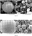
- Figure 13 shows the SEM micrograph of the cathodes: Left: LX0031 (reference prepared from M(OH) 2 precursor), Middle : Impurity free LX0142 sample (with intermediate wash), Right: Impurity containing LX0143 sample.
- Figure 14 shows the cross section SEM of sample LX0142. Obviously the desired morphology is achieved. Particles are roughly spherical and have an open porosity. In the battery electrolyte will fill the pores and facilitate the fast Li diffusion into the inner of the particles, thus enabling a high power and low DCR.
- Electrodes are prepared as follows: about 27.27 wt. % of active cathode material, 1.52 wt% polyvinylidene fluoride polymer (KF polymer L #9305, Kureha America Inc.), 1.52 wt% conductive carbon black (Super P, Erachem Comilog Inc.) and 69.70 wt% N-methyl-2-pyrrolidone (NMP) (from Sigma-Aldrich) are intimately mixed by means of high speed homogenizers. The slurry is then spread in a thin layer (typically 100 micrometer thick) on an aluminum foil by a tape-casting method.
- KF polymer L #9305 Kureha America Inc.
- Super P Erachem Comilog Inc.
- NMP N-methyl-2-pyrrolidone
- the cast film is processed through a roll-press using a 40 micrometer gap. Electrodes are punched from the film using a circular die cutter measuring 14 mm in diameter. The electrodes are then dried overnight at 90°C. The electrodes are subsequently weighed to determine the active material loading. Typically, the electrodes contain 90 wt% active materials with an active materials loading weight of about 17mg ( ⁇ 11mg/cm2). The electrodes are then put in an argon-filled glove box and assembled within the coin cell body.
- the anode is a lithium foil having a thickness of 500 micrometers (origin: Hosen); the separator is a Tonen 20MMS microporous polyethylene film.
- the coin cell is filled with a 1M solution of LIPF6 dissolved in a mixture of ethylene carbonate and dimethyl carbonate in a 1:2 volume ratio (origin: Techno Semichem Co.). Each cell is cycled at 25°C using Toscat-3100 computer-controlled galvanostatic cycling stations (from Toyo).
- Coin cells are prepared wherein the electrode consists of 96 wt% of active material.
- the electrode loading is about 6 mg/cm 2 .
- the discharge capacity of the first cycle (DQ1), the irreversible capacity of the first cycle (IRRQ1) and the rate capability of the 3C rate (in%) versus the 0.1C rate is reported.
- the discharge capacity DQ1 is measured during the first cycle in the 4.3-3.0 V range at 0.1C (in mAh/g), at 25°C.
- Irreversible capacity IRRQ1 is (Q1C-DQ1)/Q1C (in %), Q1C being the charged capacity during the 1 st cycle. Capacity fadings at Q0.1C and Q1C are expressed in % per 100 cycles.
- Table 9 ICP for impurities and surface area of cathodes Sample ID Remark ICP ICP minor BET Ni Co Mn Na S mol% mol% mol% wt% wt% m 2 /g LX0031 M(OH) 2 41.79 41.57 16.65 0.0415 0.2029 0.386 LX0143 Impurities remain 41.62 41.67 16.71 0.2955 0.3021 1.170 LX0142 Intermediate wash 41.61 41.68 16.70 0.0492 0.0653 1.387 Table 10: Coin cell test results of cathodes Sample ID Remark Coin cell/RL4345N DQ1 IRRQ1 3C rate Q 0.1C Q1C Q 1C/1C mAh/g % % %/100 %/100 %/100 LX0031 M(OH) 2 155.7 12.44 81.16 -0.32 3.26 13.74 LX0143 Impurities remain 160.7 9.94 82.51 7.15 11.97 25.63 LX0142 Intermediate wash 163.0 9.36
- Sample LX0143 which contains impurities is an example of the present invention.
- LX0142 -being free of impurities - is prepared by a more expensive process and thus is industrially not preferred. Most important, however, the impurity free sample LX0142 shows less cycle stability. The authors have observed that the presence of sodium and sulfur impurities in a desired ratio and amount, surprisingly, causes improved cycle stability
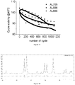
- Full cells are prepared. The full cells are of the wound pouch cell type and have a capacity of about 650 mAh. 3 different cathode materials are tested: Full cell lot# AL705 contains LX0031 which is the reference NMC obtained from hydroxide. Full cell lot AL885 contains the impurity free LX0142 and AL886 contains the impurity containing cathode LX0143. Overall AL886 - containing LX0143 which is a NMC with desired morphology having a sodium and sulfur impurity within the preferred region shows excellent results. In the following details of the cell making and testing are listed and discussed.
- the prepared positive electrodes are assembled with a negative electrode (anode) which is typically a graphite type carbon, and a porous electrically insulating membrane (separator).
- anode typically a graphite type carbon
- a porous electrically insulating membrane separatator
- the full cell is prepared by the following major steps: (a) electrode slitting (b) electrode drying (c) jellyroll winding (d) packaging.
- the present invention shows the results for (a) cycle stability, (b) capacity and rate capability, (c) bulging, (d) storage test and (e) DCR resistance tests.
- Table 11 shows the capacity and rate capability results of the full cells.
- the rate capability (in % vs. Crate) is also shown in Figure 15 .
- Table 12 shows the bulging test results and temperature properties of the full cell test.
- Table 13 shows the high temperature storage results of the full cell test (DCR and DCR increase test results).
- Figure 16 shows the cycling stability results of the full cells at room temperature, where Figure 17 shows these results at 45°C.
- the lithium metal oxide product made from metal carbonate precursors has better electrochemical properties in full cells than the one made from metal hydroxide precursor: first of all, the lithium metal oxide product made from metal carbonate precursor has a higher discharge capacity and higher efficiency. Next these products have a lower DCR at low SOC and a higher rate capability.
- the reaction equation is Li 2 CO 3 + Na 2 S 2 O 8 ⁇ 2 LiNaSO 4 + CO 2 + 1/2 O 2 .
- Figure 18 shows the XRD pattern together with a calculated pattern using the lattice constant and atomic positions for #3814 from the ICDS database.
- the main peak of the LiNaSO 4 phase is at 23.44° of 2 ⁇ .
- Other strong peaks are at 32.74° and 22.66°.
- the sodium to sulfur ratio is near to 1 (in this case the majority of the impurity phase is LiNaSO 4 )
- the X-ray scattering of the impurity phase might be strong enough to be clearly detected by powder XRD.
- - detecting the different peaks at 23.44, 32.74 and 22.66 degree is a strong evidence that the LiNaSO 4 phase is present.
- Example 11 Preparation of Li and manganese rich cathode from sodium and sulfur containing MCO 3 precursor
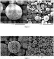
- Figure 19 shows a SEM micrograph of the precursor.
- the precursor contained 3216 ppm sodium and 5280 ppm sulfur (measured by ICP).
- the precursor was blended with Li 2 CO 3 .
- the Li:M blend ratio is 1.468. 1 kg was prepared.
- the blend is slowly heated to 800°C, then fired for 10h. After cooling the product is sieved, resulting in sample HLM330.
- the morphology of the final product is shown in Figure 20 .
- the desired morphology has been achieved. Particles are spherical and relative dense but at the same time exhibit a significant porosity.
- the BET surface area is relatively large: 4.8 m 2 /g, much larger than that of a dense powder of same shape, indicating the presence of an open meso-porous structure.
- a total of 2 wt% impurities is expected, with 86 % (17625 ppm) of the impurities present as LiNaSO 4 , and 14 % present as Li 2 SO 4 .
- the sodium to sulfur ratio is near to unity we expect the highest contribution by LiNaSO 4 .
- the material had an excellent performance in coin cells (prepared as described in Example 8).
- Example 12 532 NMC from S and Na containing MCO 3
- the precursor MCO-0099ak was blended with Li 2 CO 3 and fired.
- Several final samples were prepared with different Li:M ratios and different firing temperatures. Samples were tested by coin cell testing, as in Example 8. Despite the excellent morphology, high surface area and correct crystal structure (crystallite size and lattice constants) generally rather disappointing electrochemical properties are observed.
- Typical results are given for samples EX1518 and EX1519. These samples have a similar performance as NMC 532 prepared from M(OH) 2 precursor.
- the Li:M blend ratio is 1.02 and the sintering temperature 900°C (EX1518) and 875°C (EX1519), respectively. Table 14 summarizes the obtained results.
- the sample 60893 is a reference sample prepared from NMC 532 metal hydroxide.
- the reversible capacity is measured between 3.0 - 4.3V, at 16 mA/g and at 25°C.
- additional Li 2 SO 4 was added to the blend.
- a simplified reaction equation is LiM 1-x Na x O 2 + x Li 2 SO 4 ⁇ Li 1+x M 1-x O 2 + x LiNaSO 4
- the sample preparation was repeated.
- the MCO 3 precursor MCO-0099ak is blended with Li 2 CO 3 .
- the Li:M blend ratio is 1.02. Here however 2 mol% Li 2 SO 4 per 1 transition metal are added to the blend.
- the sodium to sulfur impurity ratio in the blend is within the desired range 0.4 - 2.0.
- the blend is fired at 875°C for 10 hours resulting in sample EX1534.
- Figure 24 shows the SEM of the sample.
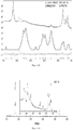
- Figure 25 shows an X-ray powder diffraction pattern of sample EX1534. Scan conditions were 2h scan, 0.02° step, 15 - 85°.
- Clearly a LiNaSO 4 secondary phase is present, since peaks are observed at 22.58, 23.22. 29.53, 30.39 and 32.53°.
- the y-axis is at logarithmic scale to enhance small peaks.
- sample EX1534 In order to remove the Na and Sulfur impurity the remainder of sample EX1534 is washed with water to remove the soluble Li and Na sulfate salt. After filtering the sample is heat treated at 700°C for 5 hours. The resulting sample EX1535 was tested in coin cells. Excellent capacity result are achieved. The irreversible capacity decreased further to 7% and the reversible capacity reached 176 mAh/g which is an exceptional high value for NMC 532. This very high value - compared to EX1534 - is caused by (1) the very low irreversible capacity and (2) by the removal of electrochemically inert sulfate salt. Furthermore, the large BET surface area (2.14 m 2 /g) contributes to the large reversible capacity. The impurity free sample however shows worse cycle stability in full cells (data not shown).
- Example 13 532 NMC from S and Na containing MCO3
- Example 12 poor results were obtained for samples EX1518 and EX1519. To further investigate if this performance is caused by a too high sodium to sulfur impurity ratio a precursor with a lower ratio within the desired region is selected and the experiment is repeated.
- the selected MCO 3 precursor was prepared by a similar method as described in Example 1:
- the resulting sample MCO-0112a contains 2230 ppm sodium and 4190 ppm sulfur, with a sodium to sulfur impurity ratio of 0.74.
- the impurities are within the desired impurity region.
- the precursor is mixed with Li 2 CO 3 .
- the Li:M blend ratio is 1.02.
- the blend is fired at 875°C for 10 hours in a flow of air, resulting in sample EX1577. Most of the Na and S impurities remain and an ICP analysis shows that the final NMC contains 2498 ppm Na and 4372 ppm sulfur.
- EX1577 has a high BET surface area of 2.12 m 2 /g, a preferred morphology with spherical, mesoporous particles, as is shown in Figure 26 (SEM micrograph) and an excellent electrochemical performance. A very low irreversible capacity of 6.1% is achieved, the reversible capacity is 174.9 mAh/g (for the usual conditions: 3.0 - 4.3V, 16 mA/g, 25°C)
- Sample EX1518 and EX1519 from Example 12 have a comparable morphology, also details of the crystal structure (lattice volume, crystallinity) are very similar. However, compared to EX1577 a poor electrochemical performance is observed. The authors believe that the main reason for the poor performance of EX1518 and EX1519 is the high sodium to sulfur impurity ratio in the carbonate precursor which exceeds the desired 0.4 ⁇ (Na / S) ⁇ 2 region. Contrary to this, sample 1577 is prepared from a precursor which is well within the preferred region.
- Example 14 111 NMC from S and Na containing MCO 3
- the base/acid flow ratio (CO 3 /M) is chosen as 1.0 to achieve a sodium to sulfur impurity ratio within the desired region 0.4 ⁇ Na/S ⁇ 2.
- the resulting sample MCO-0114g contains 2890 ppm sodium and 3660 ppm sulfur, hence the sodium to sulfur impurity ratio is 1.1.
- the precursor is mixed with Li 2 CO 3 .
- the Li:M blend ratio is 1.1.
- the blend is fired at 850°C for 10 hours in a flow of air, resulting in sample MX0809.
- MX0809 has a high BET surface area, a preferred morphology with spherical, mesoporous particles (see
- Figure 27 for a SEM micrograph and an excellent electrochemical performance.
- a very low irreversible capacity of 4.4% is achieved, the reversible capacity is 161.3 mAh/g (for the usual conditions: 3.0 -4.3V, 16 mA/g, 25°C).
- a typical mass production reference prepared from dense M(OH) 2 has an irreversible capacity > 10%, and the reversible capacity is about 155 mAh/g. The authors attribute the excellent electrochemical performance to
- Example 15 Precipitation of Na and Sulfur containing carbonate using dry power feeding
- This Example suggests a precipitation route where basically continuously a flow of MSO 4 and, simultaneously, Na 2 CO 3 powder are fed to a stirred reactor.
- the solid feeding can be done by gravimetric controlled screw feeders. This approach reduces liquid waste from 1L by 50% to 500 ml per mol precipitated MCO 3 .
- a gravimetrically controlled screw feeder was not available, a fixed amount of Na 2 CO 3 powder was added each 10 minutes, whereas MSO 4 was fed continuously. Besides the replacement of the Na 2 CO 3 flow by powder, the experiment is similar as described in Example 1.
- the metal composition is NMC 552.
- the MSO 4 flow rate is increased to achieve about the same residence time of 2.5 hours.
- the base to acid ratio (CO 3 /M) is over time fixed at 1.03.
- the precipitation achieved a MCO 3 having a sodium to sulfur impurity ratio within the preferred region 0.4 ⁇ Na/S ⁇ 2.
- the total impurity concentration is higher than expected for a liquid precipitation.
- the authors believe that the higher impurity level is caused by poor process control.
- a better process delivering a lower impurity can be achieved by accurate and continuous feeding of the Na 2 CO 3 powder. Compared to normal precipitation the precipitated carbonate was less dense and more fluffy. A better process control should significantly improve these issues as well.
- Figure 28 explains schematically why the non-continuous sold feeding can cause a higher total impurity, and why a more continuous process will solve this issue.
- the line B-1-A is the line of impurities obtained for a "normal" precipitation applying constant flow rates (see Examples 1-3). As CO 3 /M increases Na increases and sulfur decreases, but the line is not a straight line.
- Point (1) displays the impurities obtained after a normal precipitation, for example at a flow rate ratio (CO 3 /M) of 1.0.
Landscapes
- Chemical & Material Sciences (AREA)
- Organic Chemistry (AREA)
- Inorganic Chemistry (AREA)
- Chemical Kinetics & Catalysis (AREA)
- Electrochemistry (AREA)
- General Chemical & Material Sciences (AREA)
- Engineering & Computer Science (AREA)
- Manufacturing & Machinery (AREA)
- Materials Engineering (AREA)
- Battery Electrode And Active Subsutance (AREA)
- Inorganic Compounds Of Heavy Metals (AREA)
Priority Applications (1)
| Application Number | Priority Date | Filing Date | Title |
|---|---|---|---|
| PL15849645T PL3204973T3 (pl) | 2014-10-08 | 2015-09-30 | Materiał katodowy zawierający zanieczyszczenia o korzystnej morfologii i sposób wytwarzania z węglanu metalu zawierającego zanieczyszczenia |
Applications Claiming Priority (2)
| Application Number | Priority Date | Filing Date | Title |
|---|---|---|---|
| EP14188045 | 2014-10-08 | ||
| PCT/IB2015/057492 WO2016055911A1 (en) | 2014-10-08 | 2015-09-30 | Impurity containing cathode material with preferred morphology and method to prepare from impurity containing metal carbonate |
Publications (3)
| Publication Number | Publication Date |
|---|---|
| EP3204973A1 EP3204973A1 (en) | 2017-08-16 |
| EP3204973A4 EP3204973A4 (en) | 2018-05-09 |
| EP3204973B1 true EP3204973B1 (en) | 2018-12-05 |
Family
ID=51687864
Family Applications (1)
| Application Number | Title | Priority Date | Filing Date |
|---|---|---|---|
| EP15849645.5A Active EP3204973B1 (en) | 2014-10-08 | 2015-09-30 | Impurity containing cathode material with preferred morphology and method to prepare from impurity containing metal carbonate |
Country Status (9)
| Country | Link |
|---|---|
| US (2) | US10411258B2 (pl) |
| EP (1) | EP3204973B1 (pl) |
| JP (1) | JP6482659B2 (pl) |
| KR (1) | KR102004625B1 (pl) |
| CN (1) | CN106795008B (pl) |
| HU (1) | HUE042152T2 (pl) |
| PL (1) | PL3204973T3 (pl) |
| TW (1) | TWI591883B (pl) |
| WO (1) | WO2016055911A1 (pl) |
Families Citing this family (32)
| Publication number | Priority date | Publication date | Assignee | Title |
|---|---|---|---|---|
| EP3204972B1 (en) | 2014-10-08 | 2021-05-12 | Umicore | Carbonate precursors for lithium nickel manganese cobalt oxide cathode material and the method of making same |
| EP3487813A1 (en) * | 2016-07-20 | 2019-05-29 | Haldor Topsøe A/S | A method for upscalable precipitation synthesis of battery materials with tunable particle size distribution |
| EP3589585A1 (en) * | 2017-03-03 | 2020-01-08 | Umicore | PRECURSOR AND METHOD FOR PREPARING Ni BASED CATHODE MATERIAL FOR RECHARGEABLE LITHIUM ION BATTERIES |
| US11367872B2 (en) | 2017-03-03 | 2022-06-21 | Umicore | Precursor and method for preparing Ni based cathode material for rechargeable lithium ion batteries |
| WO2018162165A1 (en) | 2017-03-08 | 2018-09-13 | Umicore | Precursors of cathode materials for a rechargeable lithium ion battery |
| WO2018167533A1 (en) * | 2017-03-14 | 2018-09-20 | Umicore | Precursors for cathode material with improved secondary battery performance and method to prepare the precursors |
| US12315915B2 (en) * | 2017-07-14 | 2025-05-27 | Umicore | Ni based cathode material for rechargeable lithium-ion batteries |
| HUE051555T2 (hu) * | 2017-07-14 | 2021-03-01 | Umicore Nv | NI alapú katódanyag újratölthetõ lítium-ion akkumulátorokhoz |
| WO2019123306A1 (en) | 2017-12-22 | 2019-06-27 | Umicore | A positive electrode material for rechargeable lithium ion batteries and methods of making thereof |
| CN109987655B (zh) * | 2017-12-29 | 2021-10-01 | 荆门市格林美新材料有限公司 | 一种碱式碳酸镍的制备工艺 |
| EP3759755A4 (en) | 2018-03-02 | 2022-01-26 | Umicore | POSITIVE ELECTRODE MATERIAL FOR RECHARGEABLE LITHIUM-ION BATTERIES |
| KR102160712B1 (ko) | 2018-03-09 | 2020-09-28 | 주식회사 엘지화학 | 리튬 이차전지 |
| WO2019172637A2 (ko) | 2018-03-09 | 2019-09-12 | 주식회사 엘지화학 | 리튬 이차전지 |
| JP7021366B2 (ja) * | 2018-03-28 | 2022-02-16 | ユミコア | 充電式リチウム二次電池用正極活物質としてのリチウム遷移金属複合酸化物 |
| CN112004779B (zh) | 2018-03-29 | 2023-02-07 | 尤米科尔公司 | 用于制备可再充电锂离子蓄电池的正极材料的方法 |
| HUE068135T2 (hu) * | 2018-05-04 | 2024-12-28 | Umicore Nv | NI-alapú lítium-ionos másodlagos akkumulátor, amely fluorozott elektrolitot tartalmaz |
| CN110137489B (zh) * | 2019-06-19 | 2021-06-29 | 厦门厦钨新能源材料股份有限公司 | 具有痕量金属杂质的镍钴锰酸锂材料、制备方法及应用 |
| CN114051487B (zh) * | 2019-07-03 | 2024-03-22 | 尤米科尔公司 | 作为用于可再充电锂离子电池的正电极活性材料的锂镍锰钴复合氧化物 |
| KR102734799B1 (ko) | 2019-07-03 | 2024-11-27 | 유미코아 | 재충전 가능한 리튬 이온 배터리용 양극 활물질로서의 리튬 니켈 망간 코발트 복합 산화물 |
| CN114929624B (zh) * | 2019-12-18 | 2023-12-05 | 尤米科尔公司 | 用于可再充电锂离子电池的粉末状锂钴基氧化物阴极活性材料粉末及其制备方法 |
| CN112713269B (zh) * | 2020-12-31 | 2021-10-29 | 浙江帕瓦新能源股份有限公司 | 一种降低正极材料前驱体中钠离子和硫酸根离子含量的生产系统和生产方法 |
| US20240234707A1 (en) * | 2021-08-25 | 2024-07-11 | Sm Lab Co., Ltd. | Positive electrode active material, method for preparing same, and lithium secondary battery including positive electrode comprising same |
| KR102827965B1 (ko) * | 2021-08-25 | 2025-07-02 | 주식회사 에스엠랩 | 양극활물질, 이의 제조방법 및 이를 포함하는 양극을 포함한 리튬이차전지 |
| CN114751465B (zh) * | 2022-05-24 | 2023-06-27 | 荆门市格林美新材料有限公司 | 一种分阶段元素替代实现制备高Al均匀四氧化三钴方法 |
| CN115504522B (zh) * | 2022-09-28 | 2024-04-26 | 中伟新材料股份有限公司 | 钠离子电池正极材料前驱体及其制备方法、钠离子电池正极材料、钠离子电池和涉电设备 |
| CN115367815B (zh) * | 2022-10-26 | 2023-01-24 | 河南科隆新能源股份有限公司 | 一种多层环形孔洞镍钴铝前驱体和制备方法及其正极材料 |
| KR102723838B1 (ko) | 2022-11-11 | 2024-10-30 | (주)에코프로머티리얼즈 | 리튬 이차전지용 양극 활물질 전구체의 제조방법 |
| DE102023116756A1 (de) | 2023-06-26 | 2025-01-02 | Zentrum für Sonnenenergie- und Wasserstoff-Forschung Baden-Württemberg, Stiftung des bürgerlichen Rechts | Verfahren zur Herstellung eines Übergangsmetallcarbonats in einem kontinuierlich betriebenen Reaktor |
| GB2639991A (en) * | 2024-04-02 | 2025-10-08 | Dyson Technology Ltd | Electrode material |
| KR20250158347A (ko) * | 2024-04-30 | 2025-11-06 | 삼성에스디아이 주식회사 | 리튬 이차 전지용 양극 활물질 및 그의 제조방법 |
| GB2642817A (en) * | 2024-07-16 | 2026-01-28 | Dyson Technology Ltd | Method of manufacturing a particulate transition metalcarbonate material |
| GB2644629A (en) * | 2024-07-16 | 2026-04-29 | Dyson Technology Ltd | Method of manufacturing a particulate transition metal carbonate material |
Family Cites Families (21)
| Publication number | Priority date | Publication date | Assignee | Title |
|---|---|---|---|---|
| US3066915A (en) | 1957-11-18 | 1962-12-04 | Sr Linferd Linabery | Post puller device |
| JPH09245787A (ja) * | 1996-03-07 | 1997-09-19 | Kansai Shokubai Kagaku Kk | リチウム二次電池用正極活物質 |
| JP2001273898A (ja) * | 2000-01-20 | 2001-10-05 | Japan Storage Battery Co Ltd | 非水電解質二次電池用正極活物質およびその製造方法並びにそれを使用した非水電解質二次電池 |
| NZ520452A (en) * | 2002-10-31 | 2005-03-24 | Lg Chemical Ltd | Anion containing mixed hydroxide and lithium transition metal oxide with gradient of metal composition |
| CN100417595C (zh) | 2002-11-19 | 2008-09-10 | 比亚迪股份有限公司 | 由碳酸盐前躯体制备锂过渡金属复合氧化物的方法 |
| JP4336941B2 (ja) | 2003-01-06 | 2009-09-30 | 株式会社ジェイテクト | 負荷駆動回路 |
| TWI279019B (en) | 2003-01-08 | 2007-04-11 | Nikko Materials Co Ltd | Material for lithium secondary battery positive electrode and manufacturing method thereof |
| JP4305629B2 (ja) | 2003-03-27 | 2009-07-29 | 戸田工業株式会社 | 四酸化三マンガン粒子粉末及びその製造法、非水電解質二次電池用正極活物質及びその製造法、並びに非水電解質二次電池 |
| US7709149B2 (en) | 2004-09-24 | 2010-05-04 | Lg Chem, Ltd. | Composite precursor for aluminum-containing lithium transition metal oxide and process for preparation of the same |
| CN101229928B (zh) | 2007-01-25 | 2010-04-07 | 湖南科力远新能源股份有限公司 | 一种球形镍钴锰酸锂材料的制备方法 |
| JP4968945B2 (ja) | 2008-02-01 | 2012-07-04 | 日本化学工業株式会社 | 複合炭酸塩およびその製造方法 |
| JP4968944B2 (ja) | 2008-02-01 | 2012-07-04 | 日本化学工業株式会社 | 複合炭酸塩およびその製造方法 |
| JP5389170B2 (ja) | 2008-08-04 | 2014-01-15 | ユミコア ソシエテ アノニム | 高結晶性リチウム遷移金属酸化物 |
| WO2010147236A1 (ja) * | 2009-06-17 | 2010-12-23 | ソニー株式会社 | 非水電解質電池、非電解質電池用正極、非水電解質電池用負極、非電解質電池用セパレータ、非水電解質用電解質および非電解質電池用セパレータの製造方法 |
| WO2011040383A1 (ja) | 2009-09-30 | 2011-04-07 | 戸田工業株式会社 | 正極活物質粒子粉末及びその製造方法、並びに非水電解質二次電池 |
| ES2599646T3 (es) * | 2010-02-23 | 2017-02-02 | Toda Kogyo Corporation | Polvo de partículas precursoras de sustancia activa para un electrodo activo, polvo en partículas de sustancia activa para un electrodo positivo y batería secundaria de electrolito no acuoso |
| JPWO2012020768A1 (ja) * | 2010-08-10 | 2013-10-28 | Agcセイミケミカル株式会社 | ニッケル−コバルト含有複合化合物の製造方法 |
| KR101963103B1 (ko) | 2010-11-25 | 2019-03-28 | 바스프 에스이 | 전이 금속 혼합 산화물들을 위한 전구체의 제조 방법 |
| CN103460455B (zh) * | 2011-03-31 | 2016-03-16 | 户田工业株式会社 | 锰镍复合氧化物颗粒粉末及其制造方法、非水电解质二次电池用正极活性物质颗粒粉末及其制造方法以及非水电解质二次电池 |
| US20140308584A1 (en) | 2011-11-09 | 2014-10-16 | Gs Yuasa International Ltd. | Active material for nonaqueous electrolyte secondary battery, method for manufacturing active material, electrode for nonaqueous electrolyte secondary battery, and nonaqueous electrolyte secondary battery |
| KR101371368B1 (ko) * | 2012-02-01 | 2014-03-12 | 주식회사 엘지화학 | 리튬 복합 전이금속 산화물의 전구체 제조용 반응기 및 전구체 제조방법 |
-
2015
- 2015-09-30 PL PL15849645T patent/PL3204973T3/pl unknown
- 2015-09-30 EP EP15849645.5A patent/EP3204973B1/en active Active
- 2015-09-30 CN CN201580055057.4A patent/CN106795008B/zh active Active
- 2015-09-30 US US15/517,273 patent/US10411258B2/en active Active
- 2015-09-30 WO PCT/IB2015/057492 patent/WO2016055911A1/en not_active Ceased
- 2015-09-30 HU HUE15849645A patent/HUE042152T2/hu unknown
- 2015-09-30 KR KR1020177012208A patent/KR102004625B1/ko active Active
- 2015-09-30 JP JP2017518496A patent/JP6482659B2/ja active Active
- 2015-10-05 TW TW104132709A patent/TWI591883B/zh active
-
2019
- 2019-07-25 US US16/521,846 patent/US11462735B2/en active Active
Non-Patent Citations (1)
| Title |
|---|
| None * |
Also Published As
| Publication number | Publication date |
|---|---|
| HUE042152T2 (hu) | 2019-06-28 |
| KR102004625B1 (ko) | 2019-07-26 |
| JP2017536654A (ja) | 2017-12-07 |
| US20170309909A1 (en) | 2017-10-26 |
| US11462735B2 (en) | 2022-10-04 |
| JP6482659B2 (ja) | 2019-03-13 |
| TW201620183A (zh) | 2016-06-01 |
| WO2016055911A1 (en) | 2016-04-14 |
| EP3204973A4 (en) | 2018-05-09 |
| US10411258B2 (en) | 2019-09-10 |
| EP3204973A1 (en) | 2017-08-16 |
| KR20170065635A (ko) | 2017-06-13 |
| US20190386303A1 (en) | 2019-12-19 |
| PL3204973T3 (pl) | 2019-09-30 |
| CN106795008B (zh) | 2018-11-27 |
| TWI591883B (zh) | 2017-07-11 |
| CN106795008A (zh) | 2017-05-31 |
Similar Documents
| Publication | Publication Date | Title |
|---|---|---|
| US11462735B2 (en) | Impurity containing cathode material with preferred morphology and method to prepare from impurity containing metal carbonate | |
| KR102432535B1 (ko) | 니켈 망간 복합 수산화물과 그의 제조 방법, 비수계 전해질 이차 전지용 정극 활물질과 그의 제조 방법, 및 비수계 전해질 이차 전지 | |
| US10038190B2 (en) | Positive electrode active material for nonaqueous electrolyte secondary batteries and nonaqueous electrolyte secondary battery using positive electrode active material | |
| JP6358077B2 (ja) | ニッケルコバルト複合水酸化物粒子とその製造方法、非水電解質二次電池用正極活物質とその製造方法、および、非水電解質二次電池 | |
| US11476461B2 (en) | Precursors for cathode material with improved secondary battery performance and method to prepare the precursors | |
| JP6331983B2 (ja) | 遷移金属複合水酸化物粒子の製造方法および非水電解質二次電池用正極活物質の製造方法 | |
| EP2749537A1 (en) | Nickel composite hydroxide and method for producing the same, positive electrode active material and method for producing the same as well as nonaqueous electrolytic secondary cell | |
| US8062792B2 (en) | Processes for making dense, spherical active materials for lithium-ion cells | |
| EP2214233A1 (en) | Lithium manganate particle powder for nonaqueous electrolyte secondary battery, method for producing the same, and nonaqueous electrolyte secondary battery | |
| EP3225591A1 (en) | Nickel composite hydroxide and method for preparing same | |
| KR20190035718A (ko) | 니켈망간 복합 수산화물과 그 제조 방법, 비수계 전해질 이차 전지용 정극 활물질과 그 제조 방법, 및 비수계 전해질 이차 전지 | |
| EP4566999A1 (en) | A manganese containing precursor, cathode active material thereof and lithium-ion secondary battery | |
| Zhang et al. | Ammonia Concentration‐Directed Preferential Growth Enhancing Lithium‐Ion Diffusion in Li‐Rich Mn‐Based Oxide Cathodes | |
| Kadoma et al. | Synthesis and electrochemical properties of LiNi0. 5− xMn1. 5− xM2xO4 (M= Al, Cr) cathode materials prepared by PVA method |
Legal Events
| Date | Code | Title | Description |
|---|---|---|---|
| STAA | Information on the status of an ep patent application or granted ep patent |
Free format text: STATUS: THE INTERNATIONAL PUBLICATION HAS BEEN MADE |
|
| PUAI | Public reference made under article 153(3) epc to a published international application that has entered the european phase |
Free format text: ORIGINAL CODE: 0009012 |
|
| STAA | Information on the status of an ep patent application or granted ep patent |
Free format text: STATUS: REQUEST FOR EXAMINATION WAS MADE |
|
| 17P | Request for examination filed |
Effective date: 20170508 |
|
| AK | Designated contracting states |
Kind code of ref document: A1 Designated state(s): AL AT BE BG CH CY CZ DE DK EE ES FI FR GB GR HR HU IE IS IT LI LT LU LV MC MK MT NL NO PL PT RO RS SE SI SK SM TR |
|
| AX | Request for extension of the european patent |
Extension state: BA ME |
|
| RIN1 | Information on inventor provided before grant (corrected) |
Inventor name: HONG, HEONPYO Inventor name: OH, JINDOO Inventor name: PAULSEN, JENS |
|
| RIN1 | Information on inventor provided before grant (corrected) |
Inventor name: OH, JINDOO Inventor name: HONG, HEONPYO Inventor name: PAULSEN, JENS |
|
| DAV | Request for validation of the european patent (deleted) | ||
| DAX | Request for extension of the european patent (deleted) | ||
| A4 | Supplementary search report drawn up and despatched |
Effective date: 20180409 |
|
| RIC1 | Information provided on ipc code assigned before grant |
Ipc: C01G 53/00 20060101AFI20180403BHEP |
|
| REG | Reference to a national code |
Ref country code: DE Ref legal event code: R079 Ref document number: 602015021096 Country of ref document: DE Free format text: PREVIOUS MAIN CLASS: H01M0004525000 Ipc: C01G0053000000 |
|
| RIC1 | Information provided on ipc code assigned before grant |
Ipc: C01G 53/00 20060101AFI20180621BHEP |
|
| GRAP | Despatch of communication of intention to grant a patent |
Free format text: ORIGINAL CODE: EPIDOSNIGR1 |
|
| STAA | Information on the status of an ep patent application or granted ep patent |
Free format text: STATUS: GRANT OF PATENT IS INTENDED |
|
| INTG | Intention to grant announced |
Effective date: 20180727 |
|
| GRAS | Grant fee paid |
Free format text: ORIGINAL CODE: EPIDOSNIGR3 |
|
| GRAA | (expected) grant |
Free format text: ORIGINAL CODE: 0009210 |
|
| STAA | Information on the status of an ep patent application or granted ep patent |
Free format text: STATUS: THE PATENT HAS BEEN GRANTED |
|
| AK | Designated contracting states |
Kind code of ref document: B1 Designated state(s): AL AT BE BG CH CY CZ DE DK EE ES FI FR GB GR HR HU IE IS IT LI LT LU LV MC MK MT NL NO PL PT RO RS SE SI SK SM TR |
|
| REG | Reference to a national code |
Ref country code: GB Ref legal event code: FG4D |
|
| REG | Reference to a national code |
Ref country code: CH Ref legal event code: EP |
|
| REG | Reference to a national code |
Ref country code: AT Ref legal event code: REF Ref document number: 1072821 Country of ref document: AT Kind code of ref document: T Effective date: 20181215 |
|
| REG | Reference to a national code |
Ref country code: IE Ref legal event code: FG4D |
|
| REG | Reference to a national code |
Ref country code: DE Ref legal event code: R096 Ref document number: 602015021096 Country of ref document: DE |
|
| REG | Reference to a national code |
Ref country code: SE Ref legal event code: TRGR |
|
| REG | Reference to a national code |
Ref country code: NL Ref legal event code: MP Effective date: 20181205 |
|
| REG | Reference to a national code |
Ref country code: AT Ref legal event code: MK05 Ref document number: 1072821 Country of ref document: AT Kind code of ref document: T Effective date: 20181205 |
|
| REG | Reference to a national code |
Ref country code: LT Ref legal event code: MG4D |
|
| PG25 | Lapsed in a contracting state [announced via postgrant information from national office to epo] |
Ref country code: ES Free format text: LAPSE BECAUSE OF FAILURE TO SUBMIT A TRANSLATION OF THE DESCRIPTION OR TO PAY THE FEE WITHIN THE PRESCRIBED TIME-LIMIT Effective date: 20181205 Ref country code: AT Free format text: LAPSE BECAUSE OF FAILURE TO SUBMIT A TRANSLATION OF THE DESCRIPTION OR TO PAY THE FEE WITHIN THE PRESCRIBED TIME-LIMIT Effective date: 20181205 Ref country code: LV Free format text: LAPSE BECAUSE OF FAILURE TO SUBMIT A TRANSLATION OF THE DESCRIPTION OR TO PAY THE FEE WITHIN THE PRESCRIBED TIME-LIMIT Effective date: 20181205 Ref country code: FI Free format text: LAPSE BECAUSE OF FAILURE TO SUBMIT A TRANSLATION OF THE DESCRIPTION OR TO PAY THE FEE WITHIN THE PRESCRIBED TIME-LIMIT Effective date: 20181205 Ref country code: NO Free format text: LAPSE BECAUSE OF FAILURE TO SUBMIT A TRANSLATION OF THE DESCRIPTION OR TO PAY THE FEE WITHIN THE PRESCRIBED TIME-LIMIT Effective date: 20190305 Ref country code: LT Free format text: LAPSE BECAUSE OF FAILURE TO SUBMIT A TRANSLATION OF THE DESCRIPTION OR TO PAY THE FEE WITHIN THE PRESCRIBED TIME-LIMIT Effective date: 20181205 Ref country code: HR Free format text: LAPSE BECAUSE OF FAILURE TO SUBMIT A TRANSLATION OF THE DESCRIPTION OR TO PAY THE FEE WITHIN THE PRESCRIBED TIME-LIMIT Effective date: 20181205 Ref country code: BG Free format text: LAPSE BECAUSE OF FAILURE TO SUBMIT A TRANSLATION OF THE DESCRIPTION OR TO PAY THE FEE WITHIN THE PRESCRIBED TIME-LIMIT Effective date: 20190305 |
|
| PG25 | Lapsed in a contracting state [announced via postgrant information from national office to epo] |
Ref country code: GR Free format text: LAPSE BECAUSE OF FAILURE TO SUBMIT A TRANSLATION OF THE DESCRIPTION OR TO PAY THE FEE WITHIN THE PRESCRIBED TIME-LIMIT Effective date: 20190306 Ref country code: AL Free format text: LAPSE BECAUSE OF FAILURE TO SUBMIT A TRANSLATION OF THE DESCRIPTION OR TO PAY THE FEE WITHIN THE PRESCRIBED TIME-LIMIT Effective date: 20181205 Ref country code: RS Free format text: LAPSE BECAUSE OF FAILURE TO SUBMIT A TRANSLATION OF THE DESCRIPTION OR TO PAY THE FEE WITHIN THE PRESCRIBED TIME-LIMIT Effective date: 20181205 |
|
| PG25 | Lapsed in a contracting state [announced via postgrant information from national office to epo] |
Ref country code: NL Free format text: LAPSE BECAUSE OF FAILURE TO SUBMIT A TRANSLATION OF THE DESCRIPTION OR TO PAY THE FEE WITHIN THE PRESCRIBED TIME-LIMIT Effective date: 20181205 |
|
| REG | Reference to a national code |
Ref country code: HU Ref legal event code: AG4A Ref document number: E042152 Country of ref document: HU |
|
| PG25 | Lapsed in a contracting state [announced via postgrant information from national office to epo] |
Ref country code: IT Free format text: LAPSE BECAUSE OF FAILURE TO SUBMIT A TRANSLATION OF THE DESCRIPTION OR TO PAY THE FEE WITHIN THE PRESCRIBED TIME-LIMIT Effective date: 20181205 Ref country code: CZ Free format text: LAPSE BECAUSE OF FAILURE TO SUBMIT A TRANSLATION OF THE DESCRIPTION OR TO PAY THE FEE WITHIN THE PRESCRIBED TIME-LIMIT Effective date: 20181205 Ref country code: PT Free format text: LAPSE BECAUSE OF FAILURE TO SUBMIT A TRANSLATION OF THE DESCRIPTION OR TO PAY THE FEE WITHIN THE PRESCRIBED TIME-LIMIT Effective date: 20190405 |
|
| PG25 | Lapsed in a contracting state [announced via postgrant information from national office to epo] |
Ref country code: SK Free format text: LAPSE BECAUSE OF FAILURE TO SUBMIT A TRANSLATION OF THE DESCRIPTION OR TO PAY THE FEE WITHIN THE PRESCRIBED TIME-LIMIT Effective date: 20181205 Ref country code: RO Free format text: LAPSE BECAUSE OF FAILURE TO SUBMIT A TRANSLATION OF THE DESCRIPTION OR TO PAY THE FEE WITHIN THE PRESCRIBED TIME-LIMIT Effective date: 20181205 Ref country code: IS Free format text: LAPSE BECAUSE OF FAILURE TO SUBMIT A TRANSLATION OF THE DESCRIPTION OR TO PAY THE FEE WITHIN THE PRESCRIBED TIME-LIMIT Effective date: 20190405 Ref country code: EE Free format text: LAPSE BECAUSE OF FAILURE TO SUBMIT A TRANSLATION OF THE DESCRIPTION OR TO PAY THE FEE WITHIN THE PRESCRIBED TIME-LIMIT Effective date: 20181205 Ref country code: SM Free format text: LAPSE BECAUSE OF FAILURE TO SUBMIT A TRANSLATION OF THE DESCRIPTION OR TO PAY THE FEE WITHIN THE PRESCRIBED TIME-LIMIT Effective date: 20181205 |
|
| REG | Reference to a national code |
Ref country code: DE Ref legal event code: R097 Ref document number: 602015021096 Country of ref document: DE |
|
| PLBE | No opposition filed within time limit |
Free format text: ORIGINAL CODE: 0009261 |
|
| STAA | Information on the status of an ep patent application or granted ep patent |
Free format text: STATUS: NO OPPOSITION FILED WITHIN TIME LIMIT |
|
| PG25 | Lapsed in a contracting state [announced via postgrant information from national office to epo] |
Ref country code: SI Free format text: LAPSE BECAUSE OF FAILURE TO SUBMIT A TRANSLATION OF THE DESCRIPTION OR TO PAY THE FEE WITHIN THE PRESCRIBED TIME-LIMIT Effective date: 20181205 Ref country code: DK Free format text: LAPSE BECAUSE OF FAILURE TO SUBMIT A TRANSLATION OF THE DESCRIPTION OR TO PAY THE FEE WITHIN THE PRESCRIBED TIME-LIMIT Effective date: 20181205 |
|
| 26N | No opposition filed |
Effective date: 20190906 |
|
| PG25 | Lapsed in a contracting state [announced via postgrant information from national office to epo] |
Ref country code: TR Free format text: LAPSE BECAUSE OF FAILURE TO SUBMIT A TRANSLATION OF THE DESCRIPTION OR TO PAY THE FEE WITHIN THE PRESCRIBED TIME-LIMIT Effective date: 20181205 |
|
| PG25 | Lapsed in a contracting state [announced via postgrant information from national office to epo] |
Ref country code: MC Free format text: LAPSE BECAUSE OF FAILURE TO SUBMIT A TRANSLATION OF THE DESCRIPTION OR TO PAY THE FEE WITHIN THE PRESCRIBED TIME-LIMIT Effective date: 20181205 |
|
| REG | Reference to a national code |
Ref country code: CH Ref legal event code: PL |
|
| PG25 | Lapsed in a contracting state [announced via postgrant information from national office to epo] |
Ref country code: IE Free format text: LAPSE BECAUSE OF NON-PAYMENT OF DUE FEES Effective date: 20190930 Ref country code: LU Free format text: LAPSE BECAUSE OF NON-PAYMENT OF DUE FEES Effective date: 20190930 Ref country code: LI Free format text: LAPSE BECAUSE OF NON-PAYMENT OF DUE FEES Effective date: 20190930 Ref country code: CH Free format text: LAPSE BECAUSE OF NON-PAYMENT OF DUE FEES Effective date: 20190930 |
|
| REG | Reference to a national code |
Ref country code: BE Ref legal event code: MM Effective date: 20190930 |
|
| PG25 | Lapsed in a contracting state [announced via postgrant information from national office to epo] |
Ref country code: BE Free format text: LAPSE BECAUSE OF NON-PAYMENT OF DUE FEES Effective date: 20190930 |
|
| PG25 | Lapsed in a contracting state [announced via postgrant information from national office to epo] |
Ref country code: CY Free format text: LAPSE BECAUSE OF FAILURE TO SUBMIT A TRANSLATION OF THE DESCRIPTION OR TO PAY THE FEE WITHIN THE PRESCRIBED TIME-LIMIT Effective date: 20181205 |
|
| PG25 | Lapsed in a contracting state [announced via postgrant information from national office to epo] |
Ref country code: MT Free format text: LAPSE BECAUSE OF FAILURE TO SUBMIT A TRANSLATION OF THE DESCRIPTION OR TO PAY THE FEE WITHIN THE PRESCRIBED TIME-LIMIT Effective date: 20181205 |
|
| PG25 | Lapsed in a contracting state [announced via postgrant information from national office to epo] |
Ref country code: MK Free format text: LAPSE BECAUSE OF FAILURE TO SUBMIT A TRANSLATION OF THE DESCRIPTION OR TO PAY THE FEE WITHIN THE PRESCRIBED TIME-LIMIT Effective date: 20181205 |
|
| P01 | Opt-out of the competence of the unified patent court (upc) registered |
Effective date: 20230626 |
|
| PGFP | Annual fee paid to national office [announced via postgrant information from national office to epo] |
Ref country code: DE Payment date: 20250805 Year of fee payment: 11 |
|
| PGFP | Annual fee paid to national office [announced via postgrant information from national office to epo] |
Ref country code: PL Payment date: 20250714 Year of fee payment: 11 |
|
| PGFP | Annual fee paid to national office [announced via postgrant information from national office to epo] |
Ref country code: GB Payment date: 20250807 Year of fee payment: 11 Ref country code: HU Payment date: 20250828 Year of fee payment: 11 |
|
| PGFP | Annual fee paid to national office [announced via postgrant information from national office to epo] |
Ref country code: FR Payment date: 20250808 Year of fee payment: 11 |
|
| PGFP | Annual fee paid to national office [announced via postgrant information from national office to epo] |
Ref country code: SE Payment date: 20250812 Year of fee payment: 11 |