EP3191215B1 - Porous air permeable polytetrafluoroethylene composites with improved mechanical and thermal properties - Google Patents
Porous air permeable polytetrafluoroethylene composites with improved mechanical and thermal properties Download PDFInfo
- Publication number
- EP3191215B1 EP3191215B1 EP15781168.8A EP15781168A EP3191215B1 EP 3191215 B1 EP3191215 B1 EP 3191215B1 EP 15781168 A EP15781168 A EP 15781168A EP 3191215 B1 EP3191215 B1 EP 3191215B1
- Authority
- EP
- European Patent Office
- Prior art keywords
- eptfe
- strength
- polymer
- composite
- coating
- Prior art date
- Legal status (The legal status is an assumption and is not a legal conclusion. Google has not performed a legal analysis and makes no representation as to the accuracy of the status listed.)
- Active
Links
Images


Classifications
-
- C—CHEMISTRY; METALLURGY
- C08—ORGANIC MACROMOLECULAR COMPOUNDS; THEIR PREPARATION OR CHEMICAL WORKING-UP; COMPOSITIONS BASED THEREON
- C08J—WORKING-UP; GENERAL PROCESSES OF COMPOUNDING; AFTER-TREATMENT NOT COVERED BY SUBCLASSES C08B, C08C, C08F, C08G or C08H
- C08J7/00—Chemical treatment or coating of shaped articles made of macromolecular substances
- C08J7/04—Coating
- C08J7/046—Forming abrasion-resistant coatings; Forming surface-hardening coatings
-
- C—CHEMISTRY; METALLURGY
- C08—ORGANIC MACROMOLECULAR COMPOUNDS; THEIR PREPARATION OR CHEMICAL WORKING-UP; COMPOSITIONS BASED THEREON
- C08J—WORKING-UP; GENERAL PROCESSES OF COMPOUNDING; AFTER-TREATMENT NOT COVERED BY SUBCLASSES C08B, C08C, C08F, C08G or C08H
- C08J5/00—Manufacture of articles or shaped materials containing macromolecular substances
- C08J5/20—Manufacture of shaped structures of ion-exchange resins
- C08J5/22—Films, membranes or diaphragms
- C08J5/2287—After-treatment
- C08J5/2293—After-treatment of fluorine-containing membranes
-
- B—PERFORMING OPERATIONS; TRANSPORTING
- B01—PHYSICAL OR CHEMICAL PROCESSES OR APPARATUS IN GENERAL
- B01D—SEPARATION
- B01D67/00—Processes specially adapted for manufacturing semi-permeable membranes for separation processes or apparatus
- B01D67/0081—After-treatment of organic or inorganic membranes
- B01D67/0088—Physical treatment with compounds, e.g. swelling, coating or impregnation
-
- B—PERFORMING OPERATIONS; TRANSPORTING
- B01—PHYSICAL OR CHEMICAL PROCESSES OR APPARATUS IN GENERAL
- B01D—SEPARATION
- B01D69/00—Semi-permeable membranes for separation processes or apparatus characterised by their form, structure or properties; Manufacturing processes specially adapted therefor
- B01D69/02—Semi-permeable membranes for separation processes or apparatus characterised by their form, structure or properties; Manufacturing processes specially adapted therefor characterised by their properties
-
- B—PERFORMING OPERATIONS; TRANSPORTING
- B01—PHYSICAL OR CHEMICAL PROCESSES OR APPARATUS IN GENERAL
- B01D—SEPARATION
- B01D71/00—Semi-permeable membranes for separation processes or apparatus characterised by the material; Manufacturing processes specially adapted therefor
- B01D71/06—Organic material
- B01D71/30—Polyalkenyl halides
- B01D71/32—Polyalkenyl halides containing fluorine atoms
- B01D71/36—Polytetrafluoroethylene
-
- B—PERFORMING OPERATIONS; TRANSPORTING
- B01—PHYSICAL OR CHEMICAL PROCESSES OR APPARATUS IN GENERAL
- B01D—SEPARATION
- B01D71/00—Semi-permeable membranes for separation processes or apparatus characterised by the material; Manufacturing processes specially adapted therefor
- B01D71/06—Organic material
- B01D71/58—Other polymers having nitrogen in the main chain, with or without oxygen or carbon only
- B01D71/62—Polycondensates having nitrogen-containing heterocyclic rings in the main chain
- B01D71/64—Polyimides; Polyamide-imides; Polyester-imides; Polyamide acids or similar polyimide precursors
- B01D71/641—Polyamide-imides
-
- B—PERFORMING OPERATIONS; TRANSPORTING
- B01—PHYSICAL OR CHEMICAL PROCESSES OR APPARATUS IN GENERAL
- B01D—SEPARATION
- B01D71/00—Semi-permeable membranes for separation processes or apparatus characterised by the material; Manufacturing processes specially adapted therefor
- B01D71/06—Organic material
- B01D71/58—Other polymers having nitrogen in the main chain, with or without oxygen or carbon only
- B01D71/62—Polycondensates having nitrogen-containing heterocyclic rings in the main chain
- B01D71/64—Polyimides; Polyamide-imides; Polyester-imides; Polyamide acids or similar polyimide precursors
- B01D71/643—Polyether-imides
-
- C—CHEMISTRY; METALLURGY
- C08—ORGANIC MACROMOLECULAR COMPOUNDS; THEIR PREPARATION OR CHEMICAL WORKING-UP; COMPOSITIONS BASED THEREON
- C08J—WORKING-UP; GENERAL PROCESSES OF COMPOUNDING; AFTER-TREATMENT NOT COVERED BY SUBCLASSES C08B, C08C, C08F, C08G or C08H
- C08J7/00—Chemical treatment or coating of shaped articles made of macromolecular substances
- C08J7/04—Coating
- C08J7/0427—Coating with only one layer of a composition containing a polymer binder
-
- C—CHEMISTRY; METALLURGY
- C08—ORGANIC MACROMOLECULAR COMPOUNDS; THEIR PREPARATION OR CHEMICAL WORKING-UP; COMPOSITIONS BASED THEREON
- C08J—WORKING-UP; GENERAL PROCESSES OF COMPOUNDING; AFTER-TREATMENT NOT COVERED BY SUBCLASSES C08B, C08C, C08F, C08G or C08H
- C08J7/00—Chemical treatment or coating of shaped articles made of macromolecular substances
- C08J7/04—Coating
- C08J7/056—Forming hydrophilic coatings
-
- C—CHEMISTRY; METALLURGY
- C09—DYES; PAINTS; POLISHES; NATURAL RESINS; ADHESIVES; COMPOSITIONS NOT OTHERWISE PROVIDED FOR; APPLICATIONS OF MATERIALS NOT OTHERWISE PROVIDED FOR
- C09D—COATING COMPOSITIONS, e.g. PAINTS, VARNISHES OR LACQUERS; FILLING PASTES; CHEMICAL PAINT OR INK REMOVERS; INKS; CORRECTING FLUIDS; WOODSTAINS; PASTES OR SOLIDS FOR COLOURING OR PRINTING; USE OF MATERIALS THEREFOR
- C09D175/00—Coating compositions based on polyureas or polyurethanes; Coating compositions based on derivatives of such polymers
- C09D175/04—Polyurethanes
-
- C—CHEMISTRY; METALLURGY
- C09—DYES; PAINTS; POLISHES; NATURAL RESINS; ADHESIVES; COMPOSITIONS NOT OTHERWISE PROVIDED FOR; APPLICATIONS OF MATERIALS NOT OTHERWISE PROVIDED FOR
- C09D—COATING COMPOSITIONS, e.g. PAINTS, VARNISHES OR LACQUERS; FILLING PASTES; CHEMICAL PAINT OR INK REMOVERS; INKS; CORRECTING FLUIDS; WOODSTAINS; PASTES OR SOLIDS FOR COLOURING OR PRINTING; USE OF MATERIALS THEREFOR
- C09D179/00—Coating compositions based on macromolecular compounds obtained by reactions forming in the main chain of the macromolecule a linkage containing nitrogen, with or without oxygen, or carbon only, not provided for in groups C09D161/00 - C09D177/00
- C09D179/04—Polycondensates having nitrogen-containing heterocyclic rings in the main chain; Polyhydrazides; Polyamide acids or similar polyimide precursors
- C09D179/08—Polyimides; Polyester-imides; Polyamide-imides; Polyamide acids or similar polyimide precursors
-
- B—PERFORMING OPERATIONS; TRANSPORTING
- B01—PHYSICAL OR CHEMICAL PROCESSES OR APPARATUS IN GENERAL
- B01D—SEPARATION
- B01D2325/00—Details relating to properties of membranes
- B01D2325/22—Thermal or heat-resistance properties
-
- B—PERFORMING OPERATIONS; TRANSPORTING
- B01—PHYSICAL OR CHEMICAL PROCESSES OR APPARATUS IN GENERAL
- B01D—SEPARATION
- B01D2325/00—Details relating to properties of membranes
- B01D2325/24—Mechanical properties, e.g. strength
-
- B—PERFORMING OPERATIONS; TRANSPORTING
- B01—PHYSICAL OR CHEMICAL PROCESSES OR APPARATUS IN GENERAL
- B01D—SEPARATION
- B01D71/00—Semi-permeable membranes for separation processes or apparatus characterised by the material; Manufacturing processes specially adapted therefor
- B01D71/06—Organic material
- B01D71/54—Polyureas; Polyurethanes
-
- C—CHEMISTRY; METALLURGY
- C08—ORGANIC MACROMOLECULAR COMPOUNDS; THEIR PREPARATION OR CHEMICAL WORKING-UP; COMPOSITIONS BASED THEREON
- C08J—WORKING-UP; GENERAL PROCESSES OF COMPOUNDING; AFTER-TREATMENT NOT COVERED BY SUBCLASSES C08B, C08C, C08F, C08G or C08H
- C08J2327/00—Characterised by the use of homopolymers or copolymers of compounds having one or more unsaturated aliphatic radicals, each having only one carbon-to-carbon double bond, and at least one being terminated by a halogen; Derivatives of such polymers
- C08J2327/02—Characterised by the use of homopolymers or copolymers of compounds having one or more unsaturated aliphatic radicals, each having only one carbon-to-carbon double bond, and at least one being terminated by a halogen; Derivatives of such polymers not modified by chemical after-treatment
- C08J2327/12—Characterised by the use of homopolymers or copolymers of compounds having one or more unsaturated aliphatic radicals, each having only one carbon-to-carbon double bond, and at least one being terminated by a halogen; Derivatives of such polymers not modified by chemical after-treatment containing fluorine atoms
- C08J2327/18—Homopolymers or copolymers of tetrafluoroethylene
-
- C—CHEMISTRY; METALLURGY
- C08—ORGANIC MACROMOLECULAR COMPOUNDS; THEIR PREPARATION OR CHEMICAL WORKING-UP; COMPOSITIONS BASED THEREON
- C08J—WORKING-UP; GENERAL PROCESSES OF COMPOUNDING; AFTER-TREATMENT NOT COVERED BY SUBCLASSES C08B, C08C, C08F, C08G or C08H
- C08J2475/00—Characterised by the use of polyureas or polyurethanes; Derivatives of such polymers
- C08J2475/04—Polyurethanes
-
- C—CHEMISTRY; METALLURGY
- C08—ORGANIC MACROMOLECULAR COMPOUNDS; THEIR PREPARATION OR CHEMICAL WORKING-UP; COMPOSITIONS BASED THEREON
- C08J—WORKING-UP; GENERAL PROCESSES OF COMPOUNDING; AFTER-TREATMENT NOT COVERED BY SUBCLASSES C08B, C08C, C08F, C08G or C08H
- C08J2479/00—Characterised by the use of macromolecular compounds obtained by reactions forming in the main chain of the macromolecule a linkage containing nitrogen with or without oxygen, or carbon only, not provided for in groups C08J2461/00 - C08J2477/00
- C08J2479/04—Polycondensates having nitrogen-containing heterocyclic rings in the main chain; Polyhydrazides; Polyamide acids or similar polyimide precursors
- C08J2479/08—Polyimides; Polyester-imides; Polyamide-imides; Polyamide acids or similar polyimide precursors
Definitions
- the present invention relates generally to porous, air permeable composites having improved mechanical and thermal properties, wherein the composites comprise porous polytetrafluoroethylene having thereon at least one polymeric coating to impart the property enhancements while maintaining porosity within the composite.
- Porous polytetrafluoroethylene (PTFE) materials including expanded PTFE (ePTFE), are described in a number of patents such as US 3,953,566 to Gore , US 5,476,589 to Bacino , and US 7,306,729 to Bacino et al. These porous PTFE materials represent a family of valuable engineered material useful in numerous applications in widely varied industries such as aerospace, automotive, chemical processing, filtration, medical devices, protective clothing and alternate energy, to name but a few of the possible product applications.
- ePTFE expanded PTFE
- ePTFE and other porous PTFE materials are treated to enhance or impart additional properties specifically tailored for the targeted application.
- ePTFE which is inherently hydrophobic, and thus is not ideally suited for application requiring compatibility with aqueous solutions, can be treated or coated to render the node and fibril microstructure of the ePTFE material hydrophilic.
- ePTFE has been rendered oleophobic by treating the node and fibril structure with fluorinated materials to further lower the surface energy.
- US 5,972,449 to Chung US 6,074,738 to Von Fragstein et al.
- US 8,075,669 to Meindl EP 1,527,335 to Agarwal
- WO2006127946 / US Pat. Publn. 20070272606 to Freese and EP 1,754,528 to Deyoung are some examples of these oleophobic treatments of ePTFE.
- the primary goal of these patents is to lower the surface energy of the ePTFE by using minimal amounts of the oleophobic material so as not to change the porosity and fluid permeability.
- These oleophobic treatments are not intended to change the mechanical properties of the ePTFE significantly.
- ePTFE is an advantageous material and is used in a wide variety of industrial and commercial applications ranging from protective clothing to medical devices to battery separators to filtration.
- the discrete fillers are entrapped within the node and fibril structure of the ePTFE.
- a limitation of this approach is that only fillers that can survive the high temperature ePTFE processing can be used.
- the potential for particulation and contamination from the filler is not desirable in many applications, such as in medical and electronic devices.
- Various other approaches have been used to improve mechanical properties of ePTFE. For example, US 6,451 ,396 to Zumbrum teaches the improvement of flex endurance and US 6,737,158 to Thompson teaches the improvement of resistance to fracture by filling the pores of the ePTFE with suitable polymer matrices. However, the resulting composites add significant mass relative to the ePTFE material alone.
- US 2004/059717 describes a porous ePTFE material in which at least a portion of an oleophobic coating material is absorbed into and/or exudes from the nodes and fibrils due to the application of a solution of the coating in supercritical CO2. During application, the CO2 expands and so in turn expands the pores of the ePTFE membrane to allow entry of the coating material into the pores.
- US 2007/075014 describes a similar material comprising a hydrophobic coating to an ePTFE membrane.
- US 2004/026245 describes coating an ePTFE membrane for use in an oxygen sensor, to modify the response to temperature.
- US 6218000 describes a PTFE material with inorganic fillers, the inorganic particles being present to improve abrasion resistance.
- EP 1882514 describes the printing of a pattered layer of an elastomeric polymer to between 5-80% of the ePTFE layer thickness. so as to improve durability.
- US 2005/185867 describes improving wear resistance of ePTFE by filling voids in the ePTFE with a resin.
- US2012064273 describes the provision of a "coherent irregular network" of fused polymer particles on an ePTFE membrane surface, to improve resistance to shrinkage at high temperatures.
- enhanced ePTFE materials can be valuable by enabling additional application possibilities in diverse industries particularly where size, space or weight is a constraint.
- the present disclosure is directed to a porous air permeable ePTFE composite with enhanced mechanical and thermal properties.
- this invention describes an article comprising a node and fibril microstructure of expanded PTFE (ePTFE) that has been coated on and within the node and fibril microstructure with a suitably chosen polymer to impart the property enhancement while maintaining the porosity that contributes to fluid permeability.
- the coating polymer content of the composite is maintained between 3 and 25 weight percent of the composite, preferably between 5 and 20 weight percent.
- this invention is directed to a porous, air permeable PTFE composite having an areal mass of less than 75 gm/m 2 , preferably less than 50 gm/m 2 and most preferably less than 35 gm/m 2 and an Average Tensile Strength (ATS) (in MPa) x Z strength (in MPa) (i.e., the measure of the cohesive strength of the membrane in the thickness direction of the material) value of at least 100 MPa 2 while maintaining an air flow of less than 500 Gurley seconds.
- ATS Average Tensile Strength
- x Z strength in MPa
- the resulting composites when selecting coating polymers with appropriate temperature resistance, the resulting composites further exhibit a shrinkage of less than 10% at temperatures up to 300°C while maintaining an air flow of less than 500 Gurley seconds.
- the present invention is directed to porous, air-permeable ePTFE composite materials with improved mechanical and thermal properties.
- Figure 1 shows a schematic of the cross-section of an embodiment of an ePTFE composite 11 of the present invention.
- the microstructure of ePTFE includes in this embodiment nodes 12 and interconnecting fibrils 13.
- the pores 14 are void space within the ePTFE microstructure.
- the surface of the ePTFE microstructure is coated with a polymer 15 while still permitting air flow as measured in Gurley seconds. It is within the scope of the invention that small regions, such as depicted with reference 17, of the ePTFE surface may not be covered by the polymer 15; however, the ePTFE surfaces are generally covered by the polymer in order to obtain improved mechanical and thermal properties.
- Suitable polymeric coatings of the present invention for enhancing mechanical properties of the composite are described in more detail later herein.
- selected high temperature polymers are particularly suited and are described in more detail later herein.
- exemplary ePTFE starting materials suitable for use in the present invention are described in a number of patents such as, for example, US 3,953,566 to Gore , US 5,476,589 to Bacino , and US 7,306,729 to Bacino et al.
- Gore teaches a method to create ePTFE with a porous microstructure consisting of nodes and fibrils.
- Bacino in US 5,476,589 , teaches the creation of an ePTFE with a nonwoven like microstructure consisting of substantially fibrils.
- Bacino et al. teaches the creation of porous PTFE membranes possessing a microstructure leading to high strength and small pore size.
- Expanded PTFE (ePTFE) membranes for the present invention typically have an areal mass of 75 gm/m 2 or less, preferably 50 gm/m 2 or less and most preferably 35 gm/m 2 or less.
- ePTFE membranes with a range of microstructures are commercially manufactured by W.L. Gore and Associates, Inc. (Newark, Delaware).
- Expanded polytetrafluoroethylene is referred to herein for ease of discussion, but it is to be appreciated that expanded PTFE, expanded modified PTFE, and expanded copolymers of PTFE are all considered to be within the purview of the invention.
- Patents have been filed on expandable blends of PTFE, expandable modified PTFE, and expanded copolymers of PTFE, such as U.S. Patent No. 5,708,044 to Branca ; U.S. Patent No. 6,541 ,589 to Baillie ; U.S. Patent No. 7,531 ,611 to Sabol et a / .; U.S. Patent Application No. 11/906,877 to Ford ; and U.S. Patent Application No. 12/410,050 to Xu et al.
- Expanded PTFE components of the composites of the present invention may comprise a single ePTFE layer or multiple ePTFE layers, and the microstructure of the multilayer components may be uniform from layer to layer or within layers, or alternatively, the layers may be non-uniform from layer to layer or even within layers, all depending on the desired characteristics of the material in a given end use. Moreover, the layers may be combined prior to coating, or alternatively, may be coated separately and then layered together.
- the starting ePTFE structure may comprise a layered structure where one or more of the outer layers of ePTFE had a microstructure having a more open porosity (higher air flow) than the microstructure of one or more inner layers of ePTFE (lower air flow), and the resulting coated composite exhibits a corresponding structure and performance.
- filler materials in various forms within the conformable ePTFE tape and/or ePTFE membranes is also considered to be within the purview of the invention.
- suitable filler materials include carbon black, aerogels, metals, semi-metals, ceramics, carbon/metal particulate blends, activated carbon, and the like.
- Filler materials may be incorporated into the ePTFE tape and/or ePTFE membrane by conventional methods, such as, but not limited to, those described in U.S. Patent No. 4,995,296 to Mortimer, Jr.
- the present invention creates an ePTFE composite by coating the surface of the ePTFE microstructure with at least one suitable polymer.
- the polymer coating exists throughout the thickness of the ePTFE.
- small regions of the ePTFE microstructure may not be covered by the polymer; however, the ePTFE surfaces are generally covered by the polymer in order to obtain improved mechanical and thermal properties.
- This is schematically shown in one embodiment in Figure 1 with 15 being the polymer coating layer that is covering the nodes 12 and fibrils 13 of the ePTFE microstructure.
- the amount of the polymer used to coat the ePTFE microstructure can be varied and is dictated by the extent of the property enhancement that is desired versus the change in porosity and air flow that is acceptable. Excessive amount of coating would occlude the pores of the ePTFE resulting in significant loss in airflow. On the other hand, insufficient amount of polymer coating will result in marginal improvement in the mechanical property.
- the amount of polymer coating used to create the porous composite of this invention should be between 3 and 25 weight percent of the resulting ePTFE composite; preferably between 5 and 20 weight percent.
- the polymer content of the composite can be determined using different analytical techniques commonly known to those skilled in the art.
- the polymer content can be determined gravimetrically by digesting or dissolving the polymer out of the composite.
- thermal techniques such as thermogravimetric analysis (TGA) or differential scanning calorimetry (DSC) can be used.
- TGA thermogravimetric analysis
- DSC differential scanning calorimetry
- Spectroscopic techniques such as solid-state NMR can be suitable for determining the polymer content particularly for temperature resistant coating polymers (e.g. polyimide, polybenzimidazoles etc.) that thermally degrade in the same temperature range as PTFE thereby making the TGA technique unsuitable.
- temperature resistant coating polymers e.g. polyimide, polybenzimidazoles etc.
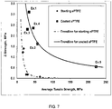
- Z-strength of ePTFE substrate is an important mechanical property for many applications. As shown schematically in Figure 2 , Z-strength is the amount of stress required in the thickness or Z direction of the substrate to cause failure due to splitting of the sample. Z-strength of ePTFE can vary over a broad range depending on the thickness and the microstructure. In general, Z-strength is lowered as the ePTFE microstructure becomes more fibrillar than nodal. As shown in Figure 7 for ePTFE membranes, this is usually accompanied by significant increase in the tensile strength of the ePTFE in the planar x and y directions.
- ATS Tensile strenght in x-direction + Tensile Strength in y-direction / 2 where x and y are orthogonal directions in the plane of the material.
- ATS Tensile strenght in x-direction + Tensile Strength in y-direction / 2 where x and y are orthogonal directions in the plane of the material.
- the measure of the ATS x Z-strength is an important value which defines the unique aspects of composites of the present invention, particularly when distinguishing over prior art composite materials.
- the goal is to coat the ePTFE node and fibril microstructure throughout the thickness of the microstructure with the chosen polymer or polymers without significantly occluding the pores.
- the coating polymer In order to improve the Z- strength of the ePTFE membrane, the coating polymer needs to be stronger than the underlying ePTFE membrane.
- the polymer selected to coat the ePTFE microstructure should have a tensile strength that is significantly higher (for example, at least about 5 times greater) than the Z-strength of the ePTFE membrane before coating.
- Tensile strength values of various polymers are readily available in the reference literatures as well as in various polymer material related websites such as www.omnexus.com and www.curbellplastics.com.
- the presence of the polymer coating throughout the thickness of the composite may be confirmed through suitable analytical techniques apparent to one of skill in the art and depending on the composition of the polymer being evaluated or detected. For example, FTIR (Fourier transform infrared spectroscopy), Raman FTIR and other suitable analytical techniques may be used to determine the presence of a polymer coating through the thickness of the composite
- the present invention significantly enhances the Z-strength of ePTFE membranes.
- An added benefit of the invented ePTFE composite is that the increase in Z-strength is also accompanied by an increase in tensile strength in both the down-web or machine direction (MD) and in the cross-web or transverse direction (TD).
- MD down-web or machine direction
- TD cross-web or transverse direction
- the magnitude of this increase depends on the ATS of the ePTFE substrates used.
- the Z-strength of ePTFE membranes with similar ATS values would be considerably lower (e.g. less than 0.1 MPa).
- Figure 8 is a graph showing the ATS x Z-strength values for both the inventive materials from the examples herein and the uncoated starting membranes (prior art) for those examples.
- the Figure shows that the ATS x Z-strength values are typically low and less than 30 MPa 2 for ePTFE membranes.
- the ATS x Z-strength values of prior art ePTFE composites such as conventional hydrophilic and oleophobic ePTFE membranes are typically low and similar to that of the uncoated ePTFE membranes mentioned above.
- the ATS x Z-strength values can be considerably increased to values of 50 MPa 2 and higher, preferably to values of 100MPa 2 and higher.
- Expanded PTFE membranes, with the node & fibril microstructure, are the preferred starting material to create the composites of the present invention.
- the areal mass of the composite depends both on the areal mass of the starting ePTFE membrane and the amount of coating polymer deposited on the membrane microstructure.
- the areal mass of the composite will be less than 75gm/m 2 , preferably less than 50 gm/m 2 and most preferably less than 35 gm/m 2 .
- the present invention through suitable choice of the coating polymer or polymers may also provide significant other benefits by improving other ambient temperature mechanical properties such as abrasion resistance, stiffness or modulus, compression resistance and creep or dimensional stability.
- a wide variety of coating polymers can be used to improve ambient temperature mechanical properties of ePTFE membranes.
- Such polymers are thermoplastic or thermosetting or elastomeric in nature.
- these polymers are polyurethanes .
- the thermal properties along with enhancing the mechanical properties of ePTFE is highly desirable.
- the composites when the composites are exposed in end use to temperatures up to 300°C, it is desired that they exhibit low shrinkage and good dimensional stability.
- Composites of this alternative embodiment exhibit ATS x Z-strength of at least 50 (MPa) 2 , a Gurley air flow of less than 500cc, and shrinkage of less than 10% at temperatures up to 300°C.
- the choice of the coating polymer is further dictated by ensuring that the polymer provides not only improved ambient temperature mechanical properties, but also temperature resistance higher than the use temperature of interest.
- ASTM tests such as Heat Distortion temperature test (ASTM D648) and Vicat Softening point test (ASTM D1525) are convenient indicators of the temperature resistance of polymers.
- maximum service temperature provided by the manufacturer is also a useful guide to the temperature resistance of the polymer.
- Heat distortion temperature, Vicat softening point and maximum service temperature are readily available in the reference literatures as well as various polymer material related websites such as www.omnexus.com and www.craftechind.com.
- Another convenient source for the long term service temperature (LTST) of various polymers is the "Periodic Table of Polymers" by Dr. Robin Kent of Tangram Technology Limited, UK and is available at www.pcn.org.
- ePTFE is suitable for continuous and intermittent use at temperatures up to 260°C and 300°C respectively
- ePTFE is prone to shrinkage at temperatures higher than ambient.
- the magnitude of the shrinkage depends on the temperature, the orientation and also on the microstructure obtained through the ePTFE processing routes followed.
- additional benefits of the coated ePTFE can be in improvement of other mechanical properties (e.g. tensile strength, stiffness or modulus, compression resistance, abrasion resistance, Z- strength etc.) at the same use temperature.
- these polymers are polyimides.
- this embodiment of the invention describes a porous ePTFE composite with shrinkage of 10% or less at a temperature of 300°C and below and can be produced by coating the node and fibril microstructure of the ePTFE substrate with a polymer with a suitable temperature resistance. It is apparent to those skilled in the art that if the composite of this invention demonstrates shrinkage of 10% or less at temperature of 300°C and below; the shrinkage at lower temperatures would be even less. Thus, the present invention can produce ePTFE composites with shrinkage of 10% or less at the targeted application temperature through appropriate choice of the coating polymer.
- the use temperature range of common interest starts at about 100°C and extends up to the PTFE service temperature of 300°C or less.
- the polymers that are used are polyurethanes or polyimides.
- polymer coating 15 onto the surface of the ePTFE microstructure can be achieved in several different ways depending on the polymer chosen. If the polymer is soluble, a solution of the polymer is created in a suitable solvent. More than one polymer can be used to create the desired coating solution. Also, if desired, various soluble additives and insoluble fillers and functional agents can be added to the final coating mix to provide additional functionalities like color, flavor, fragrance, anti-static properties, thermal and electrical conductivities, drug release etc. Care must be taken to ensure that the resulting coating polymer solution wets the porous ePTFE substrate. A good indication of that is if the porous PTFE substrate becomes clear within 30 seconds of placing a drop of the solution on its surface.
- a polymer solution will wet the porous PTFE substrate if its surface tension is lower than about 28 dynes/cm.
- wetting can also depend on the porous microstructure, the thickness of the substrate and on the presence of any co-polymer in the composition of the ePTFE membrane. If the solution does not wet due to high surface tension, then wetting solvents with surface tension lower than 28 dynes/cm can be added to the solution as long as it is compatible with the polymer solution. Few examples of common wetting solvents are methylethylketone, isopropyl alcohol, ethyl alcohol, toluene, xylene, ethyl acetate, tetrahydrofuran etc.
- the ePTFE substrate can be modified to increase the surface energy of the porous ePTFE substrate. This can be achieved by treating ePTFE surface to make it hydrophilic using any of the different methods described in the prior art as mentioned in the background to this invention.
- the porous PTFE surface can be exposed to high energy radiation such as corona or plasma treatment, but such treatments are not as effective in increasing the surface energy uniformly throughout the entire thickness.
- the coating of the microstructure is achieved by saturating the ePTFE substrate, with or without modifying surface treatment, with the polymer solution.
- polymer concentration is in the range of 0.5 to 10 weight percent, more commonly in the range of 0.5 to 5 weight percent to preserve most of the original porosity while coating the porous microstructure.
- the higher the polymer concentration in the coating solution the lower is the airflow as evidenced by the increase in Gurley number.
- the coating solution can be applied to the porous ePTFE using any of the commonly used coating methods or their combinations. Commonly used coating techniques that can be used are dip coating, Mayer rod coating slot die coating, kiss roll coating, spray coating to name a few.
- the wet saturated substrate is dried by running it through a hot air convection oven with and without infra-red heating. If polyimide precursors based on polyamic acid solutions are used, the dried substrate needs to be heated above 200°C to initiate the imidization reaction and form the polyimide coating. Drying and imidization can be done in one single step or in two separate steps. Similarly, if a thermosetting polymer or elastomer is used, the resulting coating will have to be dried and then cross-linked or cured. During drying, the porous substrate tends to shrink in all three dimensions (i.e., planar x and y, and thickness z).
- the substrate is restrained from shrinking in the planar x and y directions.
- Tenter frame or a pin frame is an example of devices that can be used to provide such restraint during drying.
- the resulting coated material while drying, is still free to shrink in the z-direction.
- the thickness of the coated composite will be lower than that of the starting ePTFE substrate.
- Another consequence of this effect is that it causes some collapse of the porous microstructure resulting in some loss in air flow or increase in the Gurley number.
- the polymer coating can also be deposited from emulsions and dispersions, provided care is taken to ensure that the polymer emulsion used is formulated to wet the ePTFE membrane. If needed, surfactants or solvents can be added to the formulation to ensure wetting of the porous PTFE substrate.
- Solution coating is the preferred method for creating the porous air-permeable PTFE composite of the present invention.
- other liquid free coating techniques can also be used.
- Vapor phase polymer deposition techniques can be used to deposit the polymer coating onto the porous microstructure. Advantages of this method is that it is free of solvents and thickness reduction and air flow loss due to microstructure collapse are significantly less than that resulting from solution coating.
- Polymers that are known to be most suitable for such vapor deposited coatings are polyacrylates and polyimides. If the polymer is insoluble in commonly used solvents, powder coating technique can also be used as long as the polymers can be made available in the form of a fine powder such that the polymer powder can infiltrate the porous microstructure.
- the particle size of the polymer powder needs to be significantly smaller than the average pore size of the porous PTFE substrate.
- polymer particle size needs to be less than one- third the mean pore size.
- this ratio can be flexible depending also on the orientation of the pores within the microstructure.
- Thickness of the ePTFE membrane and the resulting composites from it were measured using a non-contact thickness gage (Keyence Model LS-7601). Average of 3 measurements were taken.
- the bubble point was measured according to the general teachings of ASTM F31 6-03 using a Capillary Flow Porometer (Model CFP 1500 AEXL, Porous Materials Inc., Ithaca, NY).
- the sample membrane was placed into the sample chamber and wet with SilWick Silicone Fluid (Porous Materials Inc., Ithaca, NY) having a surface tension of 19.1 dynes/cm.
- the bottom clamp of the sample chamber had a 2.54 cm diameter, 3.175 mm thick porous metal disc insert (40 micron porous metal disk, Mott Metallurgical, Farmington, CT,) and the top clamp of the sample chamber had a 3.175 mm diameter hole.
- Capwin software version 6.62.1
- Gurley air flow test measures the time in seconds for 100 cm 3 of air to flow through a 6.45 cm 2 sample at 12.4 cm of water pressure. The sample was measured in a Gurley Densometer Model 4340 Automatic Densometer. Average of 3 measurements was used.
- the surface area per unit mass, expressed in units of m 2 /g, of the ePTFE membrane was measured using the Brunauer-Emmett-Teller (BET) method on a Coulter SA3100 Gas Adsorption Analyzer (Beckman Coulter Inc., Fullerton, CA). A sample was cut from the center of the ePTFE membrane sheet and placed in a small sample tube (reference number 8201151). The mass of the ePTFE sample was approximately 0.1 to 0.2 grams. The tube was placed in the Coulter SA-Prep Surface Area Outgasser, (Model SA-PREP, P/N 5102014) from Beckman Coulter, Inc., Fullerton, CA, and purged at 110 C for 2 hours with helium.
- BET Brunauer-Emmett-Teller
- sample tube was then removed from the SA-Prep Outgasser and weighed.
- sample tube was then placed into the SA3100 Gas Adsorption Analyzer and the BET surface area analysis was run in accordance with the instrument instructions using helium to calculate the free space and nitrogen as the adsorbate gas. A single measurement was recorded for each sample.
- Tensile tests were performed in both the down web or machine direction (MD) or x-direction and in the cross-web or Transverse direction (TD) or y-direction. If down-web or cross-web directions are not identified, then tensile tests can be performed in two orthogonal directions in the plane of the sample. As specified earlier, Average Tensile Strength (ATS) was calculated from these two tensile strength values.
- MD down web or machine direction
- TD Transverse direction
- ATS Average Tensile Strength
- the cohesive strength of the ePTFE membrane and the composites made using them was measured under ambient conditions using a TAPPI-541 (Zwick, Germany) device.
- a 75mm x 130mm piece of two-sided adhesive tape such as 9500PC (3M Corporation) was attached to similar sized face of the bottom platen.
- the membrane in between each of the five 25.4mm x 25.4mm test areas was slit with a scalpel to isolate the test samples.
- the upper platen which has identical five 25.4mm x 25.4mm test areas, was covered with the same two sided adhesive tape.
- the upper & bottom platens were mounted in an Instron tensile testing machine with the two platens aligned at a 90 degree angle to each other.
- the platens with the sample in between were compressed together to 3.16 kN at a rate of 12.7mm/min and held under that force for 30 seconds.
- the compressive force was then reduced to zero at a rate of 12.0kN/min.
- the platens were separated at the rate of 50.8 mm/min and the maximum force, in Newtons, to separate the platen was recorded. If the failure is cohesive in nature, the failed sample would be covering the surfaces of both the platens.
- the Z-strength of the sample in MPa (F avg in Newton)/(645.16 mm 2 ).
- the heat stability of the composite or of the uncoated ePTFE membrane was assessed by separately measuring the shrinkage in the down-web (MD) as well as in the cross-web direction (TD).
- MD down-web
- TD cross-web direction
- a 14cm x 17.8cm specimen was die cut from the test sample with the longer side oriented perpendicular to the test direction of the sample. At the mid-point of the long side of the specimen, a line was marked across the specimen. The length, L 0 of this mid-point line is 14 cm.
- the specimen was then mounted onto a 14cm x 14cm pin-frame. Only 14 cm of the longer (17.8 cm) side of the specimen was constrained within the pins. The shorter 14 cm side, aligned with the test direction, was left unrestrained.
- the shrinkage test was done in both the down web or machine direction (MD) or x-direction and in the cross-web or Transverse direction (TD) or y-direction. If down-web or cross-web directions are not identified, then tensile tests can be performed in two orthogonal directions in the plane of the sample.
- TA instrument's Q5000IR TGA was used to determine the weight percentage of the polyurethane in the composite of Example 4.
- a small sample of the composite was heated from ambient temperature to 800°C at 5°C/min in air.
- the instrument recorded the % weight loss of the sample as a function of temperature.
- the % weight loss below 400°C was taken to be the weight % polyurethane within the composite sample.
- a solid-state NMR based method is used to determine the polyimide content of the composites in Examples 1 to 3 and in Example 5. Details of the test method are as follows.
- a sample of approximately 8 to 25 mg (depending on density and other sample characteristics) is packed into a 2.5 mm solid state NMR Rotor.
- the mass is measured by weighing the rotor before and after adding the sample.
- the sample is spun following highspeed spinning protocol at approximately 28.5 kHz for 19 F NMR detection.
- the solid state 19 F NMR spectrum is acquired using parameters appropriate for PTFE.
- the parameters are to be identical to those used when collecting reference spectra of PTFE samples with varying masses added to the NMR rotors.
- the data is processed using appropriate parameters to obtain the 19 F NMR spectrum, checking that the PTFE CF2 peak position is approximately - 122 PPM.
- the peak region is integrated between approximately -103 PPM and approximately -147 PPM, checking for an appropriate integral baseline and shape and using the integration option 'Use lastscale for calibration' in which the lastscale is consistent with that used for the reference PTFE samples.
- the relative peak area of the sample spectrum is compared to the calibration curve (peak area versus PTFE mass). This will give the measured mass of PTFE present in the sample rotor.
- the calibration curve is created by collecting the 19 F NMR spectra of a series of PTFE samples using parameters identical to those used as mentioned earlier. The curve should contain integrated peak data for PTFE reference samples ranging from a mass of approximately 0.5 mg to a mass of approximately 15 mg (when using 2.5 mm NMR rotors). The measured PTFE mass is then compared to the total sample mass. The difference between these masses is equal to the polyimide portion of the sample.
- a coating mix was prepared by diluting commercially available polyimide wire enamel (Pyre ML RC-5083, Industrial Summit Technology, Parlin, New Jersey) with methylethylketone (MEK) and dimethylacetamide (DMAC).
- MEK methylethylketone
- DMAC dimethylacetamide
- This coating mix was applied onto the ePTFE membrane using a #8 Mayer rod at a speed of about 1 m/min.
- the wet membrane was then put onto a tenter frame in order to restrain from shrinkage and dried by passing through a forced air convection oven set at about 172°C at a line speed of 1 m/min and then collected on roll.
- the dried composite membrane was then again restrained on a tenter frame and run through an 8 foot long infrared (IR) oven at a speed of 0.6m/min where it was heated to about 340°C.
- IR infrared
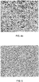
- FIGS. 4a and 4b show the SEM micrographs of the top and bottom surfaces of the porous, air-permeable composite material.
- This composite membrane having a polyimide coating over its microstructure, was also tested for polyimide content, air flow, tensile strength, Z-strength, and shrinkage.
- Example 1 The tensile strength and shrinkage measurements for this and all subsequent examples were performed in the machine (MD) and transverse (TD) directions of the coated material. The results for this Example 1 are shown in Table I Table I Measured Properties Starting ePTFE Membrane used in Example 1 ePTFE Composite of Example 1 Polyimide Content, weight % 0.0 12.9 Gurley flow, sec/100cc 14.3 45 Areal mass, gm/m 2 19.7 23.9 Tensile Strength in MD, MPa 7.1 21.1 Tensile Strength in TD, MPa 25.0 45.1 Z-strength, MPa 1.23 > 3,08** Average Tensile Strength x Z strength (MPa 2 ) 19.7 > 101.9** MD Shrinkage at 250°C, % 11.3 1.4 TD Shrinkage at 250°C; % 25.7 1.8 MD Shrinkage at 300°C. % 25.0 1.8 TD Shrinkage at 300°C, % 32.1 2.9 ** instrument limit as failure occurred in the adhesive platen interface and not in the test
- Results show significant increase in tensile strength, Z-strength and Average Tensile Strength x Z strength of the porous composite due to the polyimide coating, while maintaining significant air permeability.
- the shrinkage also is dramatically reduced up to temperatures as high as 300°C.
- a porous ePTFE membrane was made with the following properties:
- a coating mix was prepared by diluting commercially available polyimide wire enamel (Pyre ML RC-5083, Industrial Summit Technology, Parlin, New Jersey) with MEK & DMAC. The resulting coating mix had 3.7% solids and the solvent system contained about 70 weight per cent MEK. The ePTFE membrane was coated, dried and imidized as in Example 1 and then tested.
- Results show significant increase in tensile strength, Z-strength, and Average Tensile Strength x Z-strength , and a reduction in shrinkage of the porous composite at temperatures of 300°C and below due to the polyimide coating while retaining considerable air flow properties.
- a porous ePTFE membrane made in the same manner as the starting material used for Example 1 was used in this example.
- Thermoplastic polyimide pellets (Extern ® XH 1005 from Sabic Innovative Plastics, Pitsfield, MA) were dissolved in DMAc to create a 20 weight percent solution. This solution was then diluted with tetrahydrofuran (THF) to create a coating mix at 5.5 weight percent solids and the solvent system contained 83.3 weight percent THF.
- THF tetrahydrofuran
- the ePTFE membrane was coated with this mix using a #16 Mayer rod at 1 m/min line speed and dried with the convection ovens set at about 169°C. In order to reduce residual solvent, the dried composite film was then further post treated on a tenter frame by heating to about 280°C through an IR oven at a line speed of about 3m/min.
- Results show significant increase in tensile strength, Z-strength, and Average Tensile Strength x Z Strength and decrease in shrinkage of the air permeable porous composite due to the thermoplastic polyimide coating with a temperature resistance of about 250°C to 260°C.
- a porous ePTFE membrane made in the same manner as the starting material used for Example 2 was used here.
- Thermoplastic polyurethane pellets (Pellethane ® 2363-75D from Lubrizol, Wilmington, DE) were dissolved in DMAc to create a 25 weight percent solution.
- This solution was then diluted with MEK to create a coating mix at 2.1 weight percent solids and the solvent system contained 75 weight percent MEK.
- the ePTFE membrane is coated with this mix using a #32 Mayer rod at 1 m/min line speed and dried with the convection ovens set at about 169°C.
- the dried composite film was then further post treated on a tenter frame by heating to about 177°C through an IR oven at a line speed of 3m/min.
- results show significant increase in tensile strength, Z-strength and Average Tensile Strength x Z Strength of the air permeable ePTFE composite due to the thermoplastic polyurethane coating. These results also show how shrinkage can be controlled by the coating polymer choice. Since the temperature resistance of the polyurethane polymer used is about 115°C to 120°C, shrinkage at 100°C is considerably reduced due to the polyurethane coating. At 150°C, shrinkage was still reduced appreciably whereas at much higher 250°C temperature, the polyurethane coating has limited effect in reducing shrinkage due to its limited thermal stability at this temperature.
- Thermoplastic polyimide pellets (Extern ® XH1005 from Sabic Innovative Plastics, Pitsfield, MA) was dissolved in DMAc to create a 20 weight percent solution. This solution was then diluted with THF to create a coating mix at 3 weight percent solids and the solvent system contained 83.3 weight percent THF.
- the ePTFE membrane was coated with this mix using a #8 Mayer rod at 1 m/min line speed and dried with the convection ovens set at 169°C. In order to reduce residual solvent, the dried composite film was then further post treated on a tenter frame by heating to about 280°C through an IR oven at a line speed of 3 m/min.
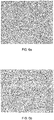
- Figures 6a and 6b show the SEM micrographs of the top and bottom surfaces of the resulting porous, air permeable composite.
- This composite membrane, having a polyimide coating was also tested for air flow, tensile strength, Z-strength, and shrinkage. The results are shown in Table V.
- Results show significant increase in tensile strength, Z-strength, Average Tensile Strength x Z-strength, and decrease in the shrinkage of the air permeable porous composite due to the thermoplastic polyimide coating with a temperature resistance of about 250°C to 260°C.
- the ePTFE membrane was made hydrophilic by solution coating the ePTFE microstructure with polyvinyl alcohol polymer followed by cross-linking with glutaraldehyde system. Hydrophilicity was checked by placing drops of deionized water on the coated membrane and within 30 seconds the coated membrane was completely wetted by the water and became transparent. The Gurley airflow of the coated membrane was about 5.5 seconds.
- the coated ePTFE was tested for mechanical properties, and the ATS and Z-strength and values were 24.5 MPa and 0.44 MPa respectively. Corresponding value of ATS x Z-strength was 10.8MPa 2 which is significantly lower than the values for the ePTFE composites of the present invention.
- ePTFE membrane was made oleophobic by coating the ePTFE microstructure with an aqueous fluoropolymer mixture.
- the coated ePTFE membrane had an oil rating of #6.
- the Gurley airflow of the coated membrane was about 25 seconds.
- the coated ePTFE was tested for mechanical properties, and the ATS and Z-strength values were 21.7 MPa and 0.79 MPa respectively. Corresponding value of ATS x Z-strength was 17.1 MPa2 which is significantly lower than the values for the ePTFE composites of the present invention.
Landscapes
- Chemical & Material Sciences (AREA)
- Chemical Kinetics & Catalysis (AREA)
- Organic Chemistry (AREA)
- Engineering & Computer Science (AREA)
- Medicinal Chemistry (AREA)
- Polymers & Plastics (AREA)
- Health & Medical Sciences (AREA)
- Manufacturing & Machinery (AREA)
- Materials Engineering (AREA)
- Life Sciences & Earth Sciences (AREA)
- Wood Science & Technology (AREA)
- Inorganic Chemistry (AREA)
- Laminated Bodies (AREA)
- Manufacture Of Porous Articles, And Recovery And Treatment Of Waste Products (AREA)
- Separation Using Semi-Permeable Membranes (AREA)
Priority Applications (1)
| Application Number | Priority Date | Filing Date | Title |
|---|---|---|---|
| EP22207641.6A EP4190433A1 (en) | 2014-09-12 | 2015-09-10 | Porous air permeable polytetrafluoroethylene composites with improved mechanical and thermal properties |
Applications Claiming Priority (2)
| Application Number | Priority Date | Filing Date | Title |
|---|---|---|---|
| US14/484,392 US20160075914A1 (en) | 2014-09-12 | 2014-09-12 | Porous Air Permeable Polytetrafluoroethylene Composites with Improved Mechanical and Thermal Properties |
| PCT/US2015/049426 WO2016040632A2 (en) | 2014-09-12 | 2015-09-10 | Porous air permeable polytetrafluoroethylene composites with improved mechanical and thermal properties |
Related Child Applications (1)
| Application Number | Title | Priority Date | Filing Date |
|---|---|---|---|
| EP22207641.6A Division EP4190433A1 (en) | 2014-09-12 | 2015-09-10 | Porous air permeable polytetrafluoroethylene composites with improved mechanical and thermal properties |
Publications (2)
| Publication Number | Publication Date |
|---|---|
| EP3191215A2 EP3191215A2 (en) | 2017-07-19 |
| EP3191215B1 true EP3191215B1 (en) | 2022-11-16 |
Family
ID=54325648
Family Applications (2)
| Application Number | Title | Priority Date | Filing Date |
|---|---|---|---|
| EP15781168.8A Active EP3191215B1 (en) | 2014-09-12 | 2015-09-10 | Porous air permeable polytetrafluoroethylene composites with improved mechanical and thermal properties |
| EP22207641.6A Pending EP4190433A1 (en) | 2014-09-12 | 2015-09-10 | Porous air permeable polytetrafluoroethylene composites with improved mechanical and thermal properties |
Family Applications After (1)
| Application Number | Title | Priority Date | Filing Date |
|---|---|---|---|
| EP22207641.6A Pending EP4190433A1 (en) | 2014-09-12 | 2015-09-10 | Porous air permeable polytetrafluoroethylene composites with improved mechanical and thermal properties |
Country Status (8)
| Country | Link |
|---|---|
| US (1) | US20160075914A1 (enExample) |
| EP (2) | EP3191215B1 (enExample) |
| JP (4) | JP6480571B2 (enExample) |
| KR (1) | KR101917546B1 (enExample) |
| CN (1) | CN107075153B (enExample) |
| AU (1) | AU2015315041B2 (enExample) |
| CA (1) | CA2960281C (enExample) |
| WO (1) | WO2016040632A2 (enExample) |
Families Citing this family (13)
| Publication number | Priority date | Publication date | Assignee | Title |
|---|---|---|---|---|
| JP6733177B2 (ja) * | 2014-07-24 | 2020-07-29 | 東レ株式会社 | 流体分離用炭素膜、流体分離膜モジュールおよび、流体分離用炭素膜の製造方法 |
| US20160075914A1 (en) * | 2014-09-12 | 2016-03-17 | W. L. Gore & Associates, Inc. | Porous Air Permeable Polytetrafluoroethylene Composites with Improved Mechanical and Thermal Properties |
| JP6937502B2 (ja) * | 2016-10-18 | 2021-09-22 | ユニチカ株式会社 | 多孔質複合フィルムおよび多孔質複合フィルムの製造方法 |
| CN109845285A (zh) | 2016-10-21 | 2019-06-04 | W.L.戈尔及同仁股份有限公司 | 包含回缩膜材料的声学保护罩组件 |
| WO2019107419A1 (ja) * | 2017-11-30 | 2019-06-06 | 株式会社新川 | ダイの実装に用いられる這い上がり防止用のptfeシート及びダイの実装方法 |
| WO2020031418A1 (ja) * | 2018-08-09 | 2020-02-13 | 住友電工ファインポリマー株式会社 | 多孔質チューブ及び多孔質チューブの製造方法 |
| US12201948B2 (en) * | 2018-10-04 | 2025-01-21 | W. L. Gore & Associates, Inc. | Unsintered expanded polytetrafluoroethylene composite membranes having dimensional stability |
| CN111389099A (zh) * | 2020-03-19 | 2020-07-10 | 兰州科天投资控股股份有限公司 | 一种高分子微孔过滤层及其制备方法和其应用 |
| CN114149611A (zh) * | 2021-11-09 | 2022-03-08 | 安徽省众望科希盟科技有限公司 | 一种使用聚酰胺酸改性膨化聚四氟乙烯的改性方法 |
| JP2025148626A (ja) * | 2022-08-26 | 2025-10-08 | 住友電気工業株式会社 | 複合多孔質体、および複合多孔質体の製造方法 |
| CN116619862B (zh) * | 2023-05-17 | 2025-12-09 | 重庆再升科技股份有限公司 | 一种柔性隔热复合材料及其制备方法 |
| CN121240970A (zh) * | 2023-05-22 | 2025-12-30 | 住友电工超效能高分子股份有限公司 | 层叠体和过滤元件 |
| CN118636551A (zh) * | 2024-05-21 | 2024-09-13 | 丹阳市科尔精密电子有限公司 | 一种高性能分散聚四氟乙烯复合材料 |
Family Cites Families (45)
| Publication number | Priority date | Publication date | Assignee | Title |
|---|---|---|---|---|
| CA962021A (en) | 1970-05-21 | 1975-02-04 | Robert W. Gore | Porous products and process therefor |
| US3953966A (en) | 1974-08-08 | 1976-05-04 | Westinghouse Electric Corporation | Combined cycle electric power plant having a control system which enables dry steam generator operation during gas turbine operation |
| JPS63191041A (ja) | 1987-02-03 | 1988-08-08 | Komori Printing Mach Co Ltd | 濃度測定位置合わせ方法 |
| US4995296A (en) | 1990-01-23 | 1991-02-26 | Chen Sheng N | Large tire bolt fixing tool |
| DE69017197T2 (de) | 1990-05-18 | 1995-09-14 | Japan Gore Tex Inc | Hydrophile poröse Membrane aus Fluoropolymer. |
| WO1992021715A1 (en) | 1991-06-04 | 1992-12-10 | Donaldson Company, Inc. | Fluid treated polytetrafluoroethylene products and their manufacture |
| US5209850A (en) | 1992-06-19 | 1993-05-11 | W. L. Gore & Associates, Inc. | Hydrophilic membranes |
| US5354587A (en) | 1993-11-15 | 1994-10-11 | W. L. Gore & Associates, Inc. | Hydrophilic compositions with increased thermal and solvent resistance |
| CN1145600A (zh) | 1994-09-02 | 1997-03-19 | W·L·戈尔及同仁股份有限公司 | 多孔聚四氟乙烯组合物 |
| US5476589A (en) | 1995-03-10 | 1995-12-19 | W. L. Gore & Associates, Inc. | Porpous PTFE film and a manufacturing method therefor |
| DE19544912A1 (de) * | 1995-12-01 | 1997-06-05 | Gore W L & Ass Gmbh | PTFE-Körper aus mikroporösem Polytetrafluorethylen mit Füllstoff und Verfahren zu dessen Herstellung |
| US5874165A (en) | 1996-06-03 | 1999-02-23 | Gore Enterprise Holdings, Inc. | Materials and method for the immobilization of bioactive species onto polymeric subtrates |
| HU227374B1 (en) | 1996-06-25 | 2011-05-30 | Gore W L & Ass Gmbh | Flexible water and oil resistant composites, producing thereof and apparel including said composites |
| DE19638416C1 (de) | 1996-09-19 | 1997-11-13 | Gore W L & Ass Gmbh | Formkörper aus einem Blend eines Fluorpolymeren und eines Thermoplasten und Verfahren zu dessen Herstellung |
| US6451396B1 (en) | 1998-02-13 | 2002-09-17 | Gore Enterprise Holdings, Inc. | Flexure endurant composite elastomer compositions |
| US7049380B1 (en) | 1999-01-19 | 2006-05-23 | Gore Enterprise Holdings, Inc. | Thermoplastic copolymer of tetrafluoroethylene and perfluoromethyl vinyl ether and medical devices employing the copolymer |
| US6541589B1 (en) | 2001-10-15 | 2003-04-01 | Gore Enterprise Holdings, Inc. | Tetrafluoroethylene copolymer |
| US20040024448A1 (en) | 2002-08-05 | 2004-02-05 | Chang James W. | Thermoplastic fluoropolymer-coated medical devices |
| US20040026245A1 (en) * | 2002-08-09 | 2004-02-12 | Vivek Agarwal | High temperature oleophobic materials |
| US7407703B2 (en) | 2002-09-20 | 2008-08-05 | Bha Group, Inc. | Composite membrane having oleophobic properties |
| US7771818B2 (en) * | 2002-09-20 | 2010-08-10 | Bha Group, Inc. | Treatment of porous article |
| US6737158B1 (en) | 2002-10-30 | 2004-05-18 | Gore Enterprise Holdings, Inc. | Porous polymeric membrane toughened composites |
| JP3664169B2 (ja) * | 2003-06-13 | 2005-06-22 | 住友電気工業株式会社 | 延伸ポリテトラフルオロエチレン成形体、その製造方法、及び複合体 |
| US20040259446A1 (en) * | 2003-06-20 | 2004-12-23 | Jain Mukesh K. | Chemical protective articles of apparel and enclosures |
| US7147378B2 (en) * | 2004-02-19 | 2006-12-12 | Gore Enterprise Holdings, Inc. | Low friction, abrasion-resistant bearing materials |
| JP4444049B2 (ja) * | 2004-09-15 | 2010-03-31 | 日東電工株式会社 | 集塵機用フィルターの製造方法 |
| US7635062B2 (en) * | 2005-03-11 | 2009-12-22 | Bha Group, Inc. | Composite membrane |
| CN101218013A (zh) | 2005-05-25 | 2008-07-09 | 戈尔企业控股股份有限公司 | 微孔基材上的多功能涂层 |
| US7531611B2 (en) | 2005-07-05 | 2009-05-12 | Gore Enterprise Holdings, Inc. | Copolymers of tetrafluoroethylene |
| US7306729B2 (en) | 2005-07-18 | 2007-12-11 | Gore Enterprise Holdings, Inc. | Porous PTFE materials and articles produced therefrom |
| US8349747B2 (en) * | 2005-08-02 | 2013-01-08 | W. L. Gore & Associates, Inc. | High seam strength architectural fabric |
| US7665615B2 (en) * | 2005-09-30 | 2010-02-23 | General Electric Company | Composite article having hydrophilic properties and method of manufacture |
| US7923054B2 (en) | 2006-04-19 | 2011-04-12 | Gore Enterprise Holdings, Inc. | Functional porous substrates for attaching biomolecules |
| US20070272606A1 (en) | 2006-05-25 | 2007-11-29 | Freese Donald T | Multi-functional coatings on microporous substrates |
| JP2008030471A (ja) * | 2006-06-29 | 2008-02-14 | Japan Gore Tex Inc | 積層型弾性チューブ |
| US20080026190A1 (en) * | 2006-07-28 | 2008-01-31 | General Electric Company | Durable membranes and methods for improving membrane durability |
| US8075669B2 (en) | 2007-04-23 | 2011-12-13 | Gore Enterprise Holdings, Inc. | Composite material |
| US20100230351A1 (en) | 2007-07-25 | 2010-09-16 | Lydall Solutech, B.V. | Hydrophilic Membrane |
| US20090191398A1 (en) | 2008-01-25 | 2009-07-30 | General Electric Company | Membranes comprising hydrophilic coatings |
| US20100167100A1 (en) * | 2008-12-26 | 2010-07-01 | David Roger Moore | Composite membrane and method for making |
| US9944044B2 (en) * | 2010-05-06 | 2018-04-17 | W. L. Gore & Associates, Inc. | Contamination resistant air permeable fabric laminate and garments made therefrom |
| US8808848B2 (en) * | 2010-09-10 | 2014-08-19 | W. L. Gore & Associates, Inc. | Porous article |
| US8819097B2 (en) | 2011-09-09 | 2014-08-26 | Texas Instruments Incorporated | Constant geometry split radix FFT |
| WO2013109337A1 (en) * | 2012-01-16 | 2013-07-25 | W.L. Gore & Associates, Inc. | Articles including expanded polytetrafluoroethylene membranes with serpentine fibrils and having a discontinuous fluoropolymer layer thereon |
| US20160075914A1 (en) * | 2014-09-12 | 2016-03-17 | W. L. Gore & Associates, Inc. | Porous Air Permeable Polytetrafluoroethylene Composites with Improved Mechanical and Thermal Properties |
-
2014
- 2014-09-12 US US14/484,392 patent/US20160075914A1/en not_active Abandoned
-
2015
- 2015-09-10 WO PCT/US2015/049426 patent/WO2016040632A2/en not_active Ceased
- 2015-09-10 CA CA2960281A patent/CA2960281C/en active Active
- 2015-09-10 JP JP2017513788A patent/JP6480571B2/ja active Active
- 2015-09-10 EP EP15781168.8A patent/EP3191215B1/en active Active
- 2015-09-10 EP EP22207641.6A patent/EP4190433A1/en active Pending
- 2015-09-10 KR KR1020177009967A patent/KR101917546B1/ko active Active
- 2015-09-10 CN CN201580048337.2A patent/CN107075153B/zh active Active
- 2015-09-10 AU AU2015315041A patent/AU2015315041B2/en active Active
-
2019
- 2019-02-07 JP JP2019020485A patent/JP6898368B2/ja active Active
- 2019-04-01 JP JP2019069779A patent/JP6898378B2/ja active Active
-
2021
- 2021-03-16 JP JP2021042457A patent/JP7045502B2/ja active Active
Also Published As
| Publication number | Publication date |
|---|---|
| CN107075153A (zh) | 2017-08-18 |
| WO2016040632A3 (en) | 2016-06-23 |
| JP6898378B2 (ja) | 2021-07-07 |
| US20160075914A1 (en) | 2016-03-17 |
| CA2960281A1 (en) | 2016-03-17 |
| JP6898368B2 (ja) | 2021-07-07 |
| WO2016040632A2 (en) | 2016-03-17 |
| JP2019090049A (ja) | 2019-06-13 |
| AU2015315041A1 (en) | 2017-03-16 |
| AU2015315041B2 (en) | 2019-04-18 |
| KR101917546B1 (ko) | 2018-11-09 |
| JP2021102771A (ja) | 2021-07-15 |
| JP2017528346A (ja) | 2017-09-28 |
| JP6480571B2 (ja) | 2019-03-13 |
| EP4190433A1 (en) | 2023-06-07 |
| JP2019135303A (ja) | 2019-08-15 |
| CA2960281C (en) | 2019-06-04 |
| JP7045502B2 (ja) | 2022-03-31 |
| EP3191215A2 (en) | 2017-07-19 |
| KR20170049600A (ko) | 2017-05-10 |
| CN107075153B (zh) | 2023-09-15 |
Similar Documents
| Publication | Publication Date | Title |
|---|---|---|
| EP3191215B1 (en) | Porous air permeable polytetrafluoroethylene composites with improved mechanical and thermal properties | |
| US10647882B2 (en) | Porous air permeable polytetrafluoroethylene composites with improved mechanical and thermal properties | |
| Chhetry et al. | A flexible and highly sensitive capacitive pressure sensor based on conductive fibers with a microporous dielectric for wearable electronics | |
| EP2613870B1 (en) | Porous article with fused thermoplastic particles | |
| TWI571300B (zh) | 親水化薄片及其製造方法 | |
| US20020144595A1 (en) | Oleophobic membrane materials by oligomer polymerization for filter venting applications | |
| JP4598524B2 (ja) | 高温用疎油性材料 | |
| Maksoud et al. | Electrospun waterproof breathable membrane with a high level of aerosol filtration | |
| EP1494790A1 (en) | Hydrophobic membrane materials for filter venting applications | |
| JP5894271B2 (ja) | 親水性延伸フルオロポリマーメンブレン複合材及びその製造方法 | |
| KR20240118860A (ko) | 치밀한 물품으로 팽창되는 페이스트 가공된 초고분자량 폴리에틸렌 | |
| US20230323066A1 (en) | Resinous membrane and water-resistant and moisture-permeable membrane | |
| WO2017017948A1 (ja) | 撥油性が付与された通気フィルタ | |
| CN111565922B (zh) | 拒油性片材的制造方法和气体传感器 | |
| EP4204131A1 (en) | Composite fluoropolymer membranes having difference surface energies | |
| JP2022103063A (ja) | 樹脂膜及び耐水透湿膜 | |
| HK1184408A (en) | Porous article with fused thermoplastic particles |
Legal Events
| Date | Code | Title | Description |
|---|---|---|---|
| STAA | Information on the status of an ep patent application or granted ep patent |
Free format text: STATUS: THE INTERNATIONAL PUBLICATION HAS BEEN MADE |
|
| PUAI | Public reference made under article 153(3) epc to a published international application that has entered the european phase |
Free format text: ORIGINAL CODE: 0009012 |
|
| STAA | Information on the status of an ep patent application or granted ep patent |
Free format text: STATUS: REQUEST FOR EXAMINATION WAS MADE |
|
| 17P | Request for examination filed |
Effective date: 20170306 |
|
| AK | Designated contracting states |
Kind code of ref document: A2 Designated state(s): AL AT BE BG CH CY CZ DE DK EE ES FI FR GB GR HR HU IE IS IT LI LT LU LV MC MK MT NL NO PL PT RO RS SE SI SK SM TR |
|
| AX | Request for extension of the european patent |
Extension state: BA ME |
|
| DAV | Request for validation of the european patent (deleted) | ||
| DAX | Request for extension of the european patent (deleted) | ||
| REG | Reference to a national code |
Ref country code: HK Ref legal event code: DE Ref document number: 1239606 Country of ref document: HK |
|
| STAA | Information on the status of an ep patent application or granted ep patent |
Free format text: STATUS: EXAMINATION IS IN PROGRESS |
|
| 17Q | First examination report despatched |
Effective date: 20191206 |
|
| GRAP | Despatch of communication of intention to grant a patent |
Free format text: ORIGINAL CODE: EPIDOSNIGR1 |
|
| STAA | Information on the status of an ep patent application or granted ep patent |
Free format text: STATUS: GRANT OF PATENT IS INTENDED |
|
| INTG | Intention to grant announced |
Effective date: 20220614 |
|
| GRAS | Grant fee paid |
Free format text: ORIGINAL CODE: EPIDOSNIGR3 |
|
| GRAA | (expected) grant |
Free format text: ORIGINAL CODE: 0009210 |
|
| STAA | Information on the status of an ep patent application or granted ep patent |
Free format text: STATUS: THE PATENT HAS BEEN GRANTED |
|
| AK | Designated contracting states |
Kind code of ref document: B1 Designated state(s): AL AT BE BG CH CY CZ DE DK EE ES FI FR GB GR HR HU IE IS IT LI LT LU LV MC MK MT NL NO PL PT RO RS SE SI SK SM TR |
|
| REG | Reference to a national code |
Ref country code: GB Ref legal event code: FG4D |
|
| REG | Reference to a national code |
Ref country code: CH Ref legal event code: EP |
|
| REG | Reference to a national code |
Ref country code: DE Ref legal event code: R096 Ref document number: 602015081615 Country of ref document: DE |
|
| REG | Reference to a national code |
Ref country code: IE Ref legal event code: FG4D |
|
| REG | Reference to a national code |
Ref country code: AT Ref legal event code: REF Ref document number: 1531432 Country of ref document: AT Kind code of ref document: T Effective date: 20221215 |
|
| REG | Reference to a national code |
Ref country code: NL Ref legal event code: FP |
|
| REG | Reference to a national code |
Ref country code: LT Ref legal event code: MG9D |
|
| REG | Reference to a national code |
Ref country code: AT Ref legal event code: MK05 Ref document number: 1531432 Country of ref document: AT Kind code of ref document: T Effective date: 20221116 |
|
| PG25 | Lapsed in a contracting state [announced via postgrant information from national office to epo] |
Ref country code: SE Free format text: LAPSE BECAUSE OF FAILURE TO SUBMIT A TRANSLATION OF THE DESCRIPTION OR TO PAY THE FEE WITHIN THE PRESCRIBED TIME-LIMIT Effective date: 20221116 Ref country code: PT Free format text: LAPSE BECAUSE OF FAILURE TO SUBMIT A TRANSLATION OF THE DESCRIPTION OR TO PAY THE FEE WITHIN THE PRESCRIBED TIME-LIMIT Effective date: 20230316 Ref country code: NO Free format text: LAPSE BECAUSE OF FAILURE TO SUBMIT A TRANSLATION OF THE DESCRIPTION OR TO PAY THE FEE WITHIN THE PRESCRIBED TIME-LIMIT Effective date: 20230216 Ref country code: LT Free format text: LAPSE BECAUSE OF FAILURE TO SUBMIT A TRANSLATION OF THE DESCRIPTION OR TO PAY THE FEE WITHIN THE PRESCRIBED TIME-LIMIT Effective date: 20221116 Ref country code: FI Free format text: LAPSE BECAUSE OF FAILURE TO SUBMIT A TRANSLATION OF THE DESCRIPTION OR TO PAY THE FEE WITHIN THE PRESCRIBED TIME-LIMIT Effective date: 20221116 Ref country code: ES Free format text: LAPSE BECAUSE OF FAILURE TO SUBMIT A TRANSLATION OF THE DESCRIPTION OR TO PAY THE FEE WITHIN THE PRESCRIBED TIME-LIMIT Effective date: 20221116 Ref country code: AT Free format text: LAPSE BECAUSE OF FAILURE TO SUBMIT A TRANSLATION OF THE DESCRIPTION OR TO PAY THE FEE WITHIN THE PRESCRIBED TIME-LIMIT Effective date: 20221116 |
|
| PG25 | Lapsed in a contracting state [announced via postgrant information from national office to epo] |
Ref country code: RS Free format text: LAPSE BECAUSE OF FAILURE TO SUBMIT A TRANSLATION OF THE DESCRIPTION OR TO PAY THE FEE WITHIN THE PRESCRIBED TIME-LIMIT Effective date: 20221116 Ref country code: PL Free format text: LAPSE BECAUSE OF FAILURE TO SUBMIT A TRANSLATION OF THE DESCRIPTION OR TO PAY THE FEE WITHIN THE PRESCRIBED TIME-LIMIT Effective date: 20221116 Ref country code: LV Free format text: LAPSE BECAUSE OF FAILURE TO SUBMIT A TRANSLATION OF THE DESCRIPTION OR TO PAY THE FEE WITHIN THE PRESCRIBED TIME-LIMIT Effective date: 20221116 Ref country code: IS Free format text: LAPSE BECAUSE OF FAILURE TO SUBMIT A TRANSLATION OF THE DESCRIPTION OR TO PAY THE FEE WITHIN THE PRESCRIBED TIME-LIMIT Effective date: 20230316 Ref country code: HR Free format text: LAPSE BECAUSE OF FAILURE TO SUBMIT A TRANSLATION OF THE DESCRIPTION OR TO PAY THE FEE WITHIN THE PRESCRIBED TIME-LIMIT Effective date: 20221116 Ref country code: GR Free format text: LAPSE BECAUSE OF FAILURE TO SUBMIT A TRANSLATION OF THE DESCRIPTION OR TO PAY THE FEE WITHIN THE PRESCRIBED TIME-LIMIT Effective date: 20230217 |
|
| P01 | Opt-out of the competence of the unified patent court (upc) registered |
Effective date: 20230516 |
|
| PG25 | Lapsed in a contracting state [announced via postgrant information from national office to epo] |
Ref country code: SM Free format text: LAPSE BECAUSE OF FAILURE TO SUBMIT A TRANSLATION OF THE DESCRIPTION OR TO PAY THE FEE WITHIN THE PRESCRIBED TIME-LIMIT Effective date: 20221116 Ref country code: RO Free format text: LAPSE BECAUSE OF FAILURE TO SUBMIT A TRANSLATION OF THE DESCRIPTION OR TO PAY THE FEE WITHIN THE PRESCRIBED TIME-LIMIT Effective date: 20221116 Ref country code: EE Free format text: LAPSE BECAUSE OF FAILURE TO SUBMIT A TRANSLATION OF THE DESCRIPTION OR TO PAY THE FEE WITHIN THE PRESCRIBED TIME-LIMIT Effective date: 20221116 Ref country code: DK Free format text: LAPSE BECAUSE OF FAILURE TO SUBMIT A TRANSLATION OF THE DESCRIPTION OR TO PAY THE FEE WITHIN THE PRESCRIBED TIME-LIMIT Effective date: 20221116 Ref country code: CZ Free format text: LAPSE BECAUSE OF FAILURE TO SUBMIT A TRANSLATION OF THE DESCRIPTION OR TO PAY THE FEE WITHIN THE PRESCRIBED TIME-LIMIT Effective date: 20221116 |
|
| RAP4 | Party data changed (patent owner data changed or rights of a patent transferred) |
Owner name: W.L. GORE & ASSOCIATES, INC. |
|
| REG | Reference to a national code |
Ref country code: DE Ref legal event code: R097 Ref document number: 602015081615 Country of ref document: DE |
|
| PG25 | Lapsed in a contracting state [announced via postgrant information from national office to epo] |
Ref country code: SK Free format text: LAPSE BECAUSE OF FAILURE TO SUBMIT A TRANSLATION OF THE DESCRIPTION OR TO PAY THE FEE WITHIN THE PRESCRIBED TIME-LIMIT Effective date: 20221116 Ref country code: AL Free format text: LAPSE BECAUSE OF FAILURE TO SUBMIT A TRANSLATION OF THE DESCRIPTION OR TO PAY THE FEE WITHIN THE PRESCRIBED TIME-LIMIT Effective date: 20221116 |
|
| PLBE | No opposition filed within time limit |
Free format text: ORIGINAL CODE: 0009261 |
|
| STAA | Information on the status of an ep patent application or granted ep patent |
Free format text: STATUS: NO OPPOSITION FILED WITHIN TIME LIMIT |
|
| 26N | No opposition filed |
Effective date: 20230817 |
|
| PG25 | Lapsed in a contracting state [announced via postgrant information from national office to epo] |
Ref country code: SI Free format text: LAPSE BECAUSE OF FAILURE TO SUBMIT A TRANSLATION OF THE DESCRIPTION OR TO PAY THE FEE WITHIN THE PRESCRIBED TIME-LIMIT Effective date: 20221116 |
|
| REG | Reference to a national code |
Ref country code: CH Ref legal event code: PL |
|
| PG25 | Lapsed in a contracting state [announced via postgrant information from national office to epo] |
Ref country code: LU Free format text: LAPSE BECAUSE OF NON-PAYMENT OF DUE FEES Effective date: 20230910 |
|
| PG25 | Lapsed in a contracting state [announced via postgrant information from national office to epo] |
Ref country code: LU Free format text: LAPSE BECAUSE OF NON-PAYMENT OF DUE FEES Effective date: 20230910 Ref country code: MC Free format text: LAPSE BECAUSE OF FAILURE TO SUBMIT A TRANSLATION OF THE DESCRIPTION OR TO PAY THE FEE WITHIN THE PRESCRIBED TIME-LIMIT Effective date: 20221116 |
|
| REG | Reference to a national code |
Ref country code: IE Ref legal event code: MM4A |
|
| PG25 | Lapsed in a contracting state [announced via postgrant information from national office to epo] |
Ref country code: IE Free format text: LAPSE BECAUSE OF NON-PAYMENT OF DUE FEES Effective date: 20230910 |
|
| PG25 | Lapsed in a contracting state [announced via postgrant information from national office to epo] |
Ref country code: CH Free format text: LAPSE BECAUSE OF NON-PAYMENT OF DUE FEES Effective date: 20230930 |
|
| PG25 | Lapsed in a contracting state [announced via postgrant information from national office to epo] |
Ref country code: IE Free format text: LAPSE BECAUSE OF NON-PAYMENT OF DUE FEES Effective date: 20230910 Ref country code: CH Free format text: LAPSE BECAUSE OF NON-PAYMENT OF DUE FEES Effective date: 20230930 |
|
| PG25 | Lapsed in a contracting state [announced via postgrant information from national office to epo] |
Ref country code: BG Free format text: LAPSE BECAUSE OF FAILURE TO SUBMIT A TRANSLATION OF THE DESCRIPTION OR TO PAY THE FEE WITHIN THE PRESCRIBED TIME-LIMIT Effective date: 20221116 |
|
| PG25 | Lapsed in a contracting state [announced via postgrant information from national office to epo] |
Ref country code: BG Free format text: LAPSE BECAUSE OF FAILURE TO SUBMIT A TRANSLATION OF THE DESCRIPTION OR TO PAY THE FEE WITHIN THE PRESCRIBED TIME-LIMIT Effective date: 20221116 |
|
| PG25 | Lapsed in a contracting state [announced via postgrant information from national office to epo] |
Ref country code: CY Free format text: LAPSE BECAUSE OF FAILURE TO SUBMIT A TRANSLATION OF THE DESCRIPTION OR TO PAY THE FEE WITHIN THE PRESCRIBED TIME-LIMIT; INVALID AB INITIO Effective date: 20150910 |
|
| PG25 | Lapsed in a contracting state [announced via postgrant information from national office to epo] |
Ref country code: HU Free format text: LAPSE BECAUSE OF FAILURE TO SUBMIT A TRANSLATION OF THE DESCRIPTION OR TO PAY THE FEE WITHIN THE PRESCRIBED TIME-LIMIT; INVALID AB INITIO Effective date: 20150910 |
|
| PGFP | Annual fee paid to national office [announced via postgrant information from national office to epo] |
Ref country code: NL Payment date: 20250820 Year of fee payment: 11 |
|
| PGFP | Annual fee paid to national office [announced via postgrant information from national office to epo] |
Ref country code: DE Payment date: 20250820 Year of fee payment: 11 |
|
| PGFP | Annual fee paid to national office [announced via postgrant information from national office to epo] |
Ref country code: IT Payment date: 20250820 Year of fee payment: 11 |
|
| PGFP | Annual fee paid to national office [announced via postgrant information from national office to epo] |
Ref country code: GB Payment date: 20250820 Year of fee payment: 11 Ref country code: BE Payment date: 20250820 Year of fee payment: 11 |
|
| PGFP | Annual fee paid to national office [announced via postgrant information from national office to epo] |
Ref country code: FR Payment date: 20250821 Year of fee payment: 11 |
|
| PG25 | Lapsed in a contracting state [announced via postgrant information from national office to epo] |
Ref country code: TR Free format text: LAPSE BECAUSE OF FAILURE TO SUBMIT A TRANSLATION OF THE DESCRIPTION OR TO PAY THE FEE WITHIN THE PRESCRIBED TIME-LIMIT Effective date: 20221116 |