EP3181031A2 - Saugreinigungsgerät sowie verfahren zum betrieb eines saugreinigungsgerätes - Google Patents
Saugreinigungsgerät sowie verfahren zum betrieb eines saugreinigungsgerätes Download PDFInfo
- Publication number
- EP3181031A2 EP3181031A2 EP16202318.8A EP16202318A EP3181031A2 EP 3181031 A2 EP3181031 A2 EP 3181031A2 EP 16202318 A EP16202318 A EP 16202318A EP 3181031 A2 EP3181031 A2 EP 3181031A2
- Authority
- EP
- European Patent Office
- Prior art keywords
- accumulator
- blower
- fan
- cleaning device
- air flow
- Prior art date
- Legal status (The legal status is an assumption and is not a legal conclusion. Google has not performed a legal analysis and makes no representation as to the accuracy of the status listed.)
- Granted
Links
Images

Classifications
-
- A—HUMAN NECESSITIES
- A47—FURNITURE; DOMESTIC ARTICLES OR APPLIANCES; COFFEE MILLS; SPICE MILLS; SUCTION CLEANERS IN GENERAL
- A47L—DOMESTIC WASHING OR CLEANING; SUCTION CLEANERS IN GENERAL
- A47L9/00—Details or accessories of suction cleaners, e.g. mechanical means for controlling the suction or for effecting pulsating action; Storing devices specially adapted to suction cleaners or parts thereof; Carrying-vehicles specially adapted for suction cleaners
- A47L9/28—Installation of the electric equipment, e.g. adaptation or attachment to the suction cleaner; Controlling suction cleaners by electric means
- A47L9/2868—Arrangements for power supply of vacuum cleaners or the accessories thereof
- A47L9/2884—Details of arrangements of batteries or their installation
-
- A—HUMAN NECESSITIES
- A47—FURNITURE; DOMESTIC ARTICLES OR APPLIANCES; COFFEE MILLS; SPICE MILLS; SUCTION CLEANERS IN GENERAL
- A47L—DOMESTIC WASHING OR CLEANING; SUCTION CLEANERS IN GENERAL
- A47L9/00—Details or accessories of suction cleaners, e.g. mechanical means for controlling the suction or for effecting pulsating action; Storing devices specially adapted to suction cleaners or parts thereof; Carrying-vehicles specially adapted for suction cleaners
- A47L9/10—Filters; Dust separators; Dust removal; Automatic exchange of filters
- A47L9/12—Dry filters
- A47L9/122—Dry filters flat
-
- A—HUMAN NECESSITIES
- A47—FURNITURE; DOMESTIC ARTICLES OR APPLIANCES; COFFEE MILLS; SPICE MILLS; SUCTION CLEANERS IN GENERAL
- A47L—DOMESTIC WASHING OR CLEANING; SUCTION CLEANERS IN GENERAL
- A47L9/00—Details or accessories of suction cleaners, e.g. mechanical means for controlling the suction or for effecting pulsating action; Storing devices specially adapted to suction cleaners or parts thereof; Carrying-vehicles specially adapted for suction cleaners
- A47L9/28—Installation of the electric equipment, e.g. adaptation or attachment to the suction cleaner; Controlling suction cleaners by electric means
- A47L9/2805—Parameters or conditions being sensed
-
- A—HUMAN NECESSITIES
- A47—FURNITURE; DOMESTIC ARTICLES OR APPLIANCES; COFFEE MILLS; SPICE MILLS; SUCTION CLEANERS IN GENERAL
- A47L—DOMESTIC WASHING OR CLEANING; SUCTION CLEANERS IN GENERAL
- A47L9/00—Details or accessories of suction cleaners, e.g. mechanical means for controlling the suction or for effecting pulsating action; Storing devices specially adapted to suction cleaners or parts thereof; Carrying-vehicles specially adapted for suction cleaners
- A47L9/28—Installation of the electric equipment, e.g. adaptation or attachment to the suction cleaner; Controlling suction cleaners by electric means
- A47L9/2836—Installation of the electric equipment, e.g. adaptation or attachment to the suction cleaner; Controlling suction cleaners by electric means characterised by the parts which are controlled
- A47L9/2842—Suction motors or blowers
-
- A—HUMAN NECESSITIES
- A47—FURNITURE; DOMESTIC ARTICLES OR APPLIANCES; COFFEE MILLS; SPICE MILLS; SUCTION CLEANERS IN GENERAL
- A47L—DOMESTIC WASHING OR CLEANING; SUCTION CLEANERS IN GENERAL
- A47L9/00—Details or accessories of suction cleaners, e.g. mechanical means for controlling the suction or for effecting pulsating action; Storing devices specially adapted to suction cleaners or parts thereof; Carrying-vehicles specially adapted for suction cleaners
- A47L9/28—Installation of the electric equipment, e.g. adaptation or attachment to the suction cleaner; Controlling suction cleaners by electric means
- A47L9/2868—Arrangements for power supply of vacuum cleaners or the accessories thereof
- A47L9/2873—Docking units or charging stations
-
- A—HUMAN NECESSITIES
- A47—FURNITURE; DOMESTIC ARTICLES OR APPLIANCES; COFFEE MILLS; SPICE MILLS; SUCTION CLEANERS IN GENERAL
- A47L—DOMESTIC WASHING OR CLEANING; SUCTION CLEANERS IN GENERAL
- A47L9/00—Details or accessories of suction cleaners, e.g. mechanical means for controlling the suction or for effecting pulsating action; Storing devices specially adapted to suction cleaners or parts thereof; Carrying-vehicles specially adapted for suction cleaners
- A47L9/28—Installation of the electric equipment, e.g. adaptation or attachment to the suction cleaner; Controlling suction cleaners by electric means
- A47L9/2889—Safety or protection devices or systems, e.g. for prevention of motor over-heating or for protection of the user
-
- A—HUMAN NECESSITIES
- A47—FURNITURE; DOMESTIC ARTICLES OR APPLIANCES; COFFEE MILLS; SPICE MILLS; SUCTION CLEANERS IN GENERAL
- A47L—DOMESTIC WASHING OR CLEANING; SUCTION CLEANERS IN GENERAL
- A47L2201/00—Robotic cleaning machines, i.e. with automatic control of the travelling movement or the cleaning operation
- A47L2201/02—Docking stations; Docking operations
- A47L2201/022—Recharging of batteries
Definitions
- the invention relates first to a method for operating a Saugquels advocatess, in particular a vacuum robot, wherein during a suction suction material is removed by means of a blower of Saugquels advocatess from a surface to be cleaned and wherein the blower is operated by means of a rechargeable battery.
- the invention relates to a Saugquels réelle, in particular a suction robot, with a blower for conveying suction material from a surface to be cleaned in a suction chamber of the Saugquels expertss and with an accumulator for operating the blower, wherein generated by the accumulator heat generated by one of the blower Air flow is dissipatable.
- Saugtherapiesowski and methods for operating such Saugtherapiesmaschine are known in the art.
- Saugtherapiesmaschinen may be in particular self-propelled vacuum robot or combined suction-wiper robot or hand vacuum cleaner, especially hand-held cordless vacuum cleaners act.
- the publication WO 2005/099547 A1 discloses, for example, a vacuum cleaner with a power supply module which is cooled during a suction operation of the vacuum cleaner by means of a suction air flow of the blower.
- the air flow of the air flow is designed so that the air flow from a suction chamber of the vacuum cleaner via a receiving space in which the power supply module is arranged, flows to the fan.
- This measure causes a cooling of the accumulator in the suction operation of the vacuum cleaner, whereby the life of the accumulator can be extended.
- the invention initially proposes a method for operating the Saug lenderss confuses, in which the accumulator is cooled during a charging of the accumulator by an air flow generated by the fan.
- the vacuum cleaning device stands, for example, in a base station, which has a charging device for charging the accumulator.
- the vacuum cleaning device can also be connected directly, ie without interposition of a base station, to a charging device.
- the battery is cooled during the charging process by its own blower of the vacuum cleaning device.
- the blower is thus also operated during a charging process of the accumulator, so that the air flow generated by the blower flows past the accumulator or several accumulator cells of the accumulator and thus causes cooling of the accumulator.
- the usually rising in a charging temperature of the accumulator can thus be reduced. This causes a gentler charging process and an extension of the life of the battery. Furthermore, if necessary, the charging time required for the charging process can also be reduced.
- the fan be operated during a charging process with a power of about 10 watts to 100 watts.
- the fan is preferably operated during the charging process with a lowest possible power, which is advantageously lower than that provided for a conventional suction on carpet power of the fan.
- a blower power of about 10 watts to 100 watts is proposed, but the fan may optionally be operated at even lower power during charging.
- this reduces the noise emission by the blower and the energy absorbed by the blower during the charging process and on the other hand is sufficient to sufficiently cool the accumulator during the charging process, so that the desired effects of charging time reduction and / or the extension of the life of the accumulator can be achieved.
- the air flow conveyed by the fan be filtered before reaching the accumulator by means of a filter element.
- the filter element can be, for example, a coarse material filter, in particular a filter mesh with a mesh width of 0.4 to 1.0 mm, or alternatively a fine filter for filtering finer particles.
- the filter element may be formed as a planar, in particular also pleated, filter, or as a three-dimensional filter element, for example as a candle filter.
- two successively arranged filter elements for example, first a coarse material filter and then a fine filter may be provided in the flow direction in front of the accumulator.
- a secondary air opening arranged in front of the accumulator be opened, so that the accumulator is cooled by secondary air entering the vacuum cleaner through the secondary air opening.
- the air required for the cooling of the accumulator is sucked through a secondary air opening of the vacuum cleaning device, so that cold, preferably clean, ambient air flows to the accumulator and the blower.
- the secondary air opening is arranged in front of the accumulator relative to the flow direction of the air flow.
- the secondary air drawn in by the blower thus first flows past the accumulator through the secondary air opening, possibly through a filter element to the fan and is finally discharged on the pressure side of the blower via an outlet opening of the vacuum cleaner back to the environment. It is advisable to obstruct the flow path used during the suction operation between the suction chamber and the blower, so that only air can be sucked through the secondary air opening. Preferably, this flow path is blocked at the same time as the opening of the secondary air opening, for example triggered by a start of a charging operation detected by a control device of the vacuum cleaning device.
- the air provided for cooling the accumulator air does not flow through a secondary air opening in the Saugtherapies réelle, but as in a conventional suction operation via a suction port of Saugquels advocatess, the air first flows into the suction chamber of Saugquels advocatess, there by means of a filter element is freed from present in the air flow suction material and then flows to the accumulator and then the fan.
- the air flow which has the same flow path as an air flow during the suction operation of the vacuum cleaning device for conveying suction material from a surface to be cleaned in the suction chamber of Saugquels advocatess.
- the fan is automatically switched on at the beginning of a charging process, in particular when producing an electrical contact between the accumulator and a charging device for the accumulator.
- a control device of the vacuum cleaning device detects the beginning of the charging process and then switches on the fan.
- the beginning of the charging process can be recognized in particular by the contact of the charging device with the accumulator.
- the control device may advantageously be connected to a conventional contact sensor, which transmits a signal via the production of the electrical contact.
- the fan is thus advantageously started in particular at the same time as the beginning of the charging process, although a delayed switching on of the fan may also be provided, in particular as a function of a current temperature of the rechargeable battery.
- the blower can also be operated in principle temperature-controlled, wherein the blower is switched on or off depending on a current temperature of the accumulator during the charging process or in dependence on a current temperature with a different power, in particular speed operated.
- the charging process is automatically started at a connection of the accumulator to the charging device, so that as a result of the operation of the fan is included in the preparation of the electrical contact.
- a vacuum robot proposed with a blower for conveying suction material from a surface to be cleaned in a suction chamber of Saugquels experts with an accumulator for operating the blower, wherein of the accumulator generated heat is dissipated by an air flow generated by the fan, and wherein the Saugquels réelle has a control device which is adapted to operate the fan during a charging of the accumulator to cool the accumulator by means of the air flow generated by the fan.
- the Saugtherapies choir is basically designed so that generated by the accumulator heat during a charging by the air flow generated by the fan can be discharged. This is achieved in particular by the fact that the air flow generated by the blower passes by the accumulator in order to reach the blower. Thus, the accumulator can be cooled both during the suction operation and during the charging of the air flow.
- control device is set up to switch on the blower at the beginning of a charging process of the rechargeable battery, in particular when establishing an electrical contact between the rechargeable battery and a charging device for the rechargeable battery.
- the control device can be in connection with a contact sensor, which provides a mechanical contact of the vacuum cleaning device to a base station detected. Alternatively, a mechanical contact between the accumulator and a charging device can be detected. Furthermore, it is also possible that the control device detects a current flow (charging current) between the charging device and the accumulator and then turns on the fan.
- the charging device can be integrated into a base station or be designed to be particularly simple as a stand alone charger with an electrical connection element for the accumulator of Saugtherapies expertss.
- the accumulator with an accumulator housing forms a arranged in the Saug lenderss réelle module unit, wherein the modular unit also forms a portion of a flow channel for the air flow, so that the air flow through the module unit can be conveyed.
- the air flow generated by the blower no longer flows from the outside via the accumulator, but is passed through the module unit and thus also the accumulator or a battery housing of the accumulator, so that the accumulator, in particular one or more accumulator cells of the accumulator, directly is cooled.
- the accumulator or accumulator housing is used as a flow path for the air flow, which optionally also the geometric dimensions of Saugquels expertss can be reduced because in a receiving space of Saugquels experts for the accumulator does not need to be additionally created a flow path for the air flow.
- the module unit is integrated as a section of the flow channel in the flow channel, so that the air flow in the flow through the flow channel also flows directly through the module unit and thereby cools the accumulator.
- the module unit is for this purpose connected to adjacent sections of the flow channel, wherein preferably a fluid-tight connection of the channel sections for the lossless transition of the suction air flow from an adjacent channel section into the module unit and / or from the module unit into an adjacent channel section.
- the interfaces between the module unit and the adjacent channel sections of the flow channel advantageously have seals and / or are glued together, welded or the like.
- the accumulator has one or more accumulator cells, which are arranged in an annular manner within the flow channel, based on a cross section of the flow channel.
- the battery cells can occupy the channel portion of the flow channel, which is formed by the module unit, annular, so that the guided through the flow channel air flow flows through the annular arrangement of the battery cells.
- the annular arrangement in cross-section is a circular arrangement, so that substantially all accumulator cells are cooled in the same way. If the flow channel is not circular, but for example oval, rectangular or the like is executed, the arrangement of the battery cells can of course also take this form.
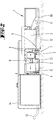
- the vacuum cleaning device 1 shown in the figures is designed as a self-propelled vacuum robot.
- the vacuum cleaning device 1 has wheels 12 for moving the vacuum cleaning device 1 over a surface to be cleaned.
- the vacuum cleaning device 1 is supported by means of a brush 11 on the surface to be cleaned.
- the brush 11 is arranged in the region of a suction nozzle 16, via which suction material from the surface to be cleaned in a suction chamber 5 of the Saugquelsuzes 1 is conveyed.
- the collected suction material is collected in the suction chamber 5.
- the vacuum cleaning device 1 further comprises a fan 2, which generates an air flow, which promotes the suction material from the surface to be cleaned in the suction chamber 5.
- a fan 2 which generates an air flow, which promotes the suction material from the surface to be cleaned in the suction chamber 5.
- two filter elements 6 are arranged, which filter the flowing of the surface to be cleaned in the suction chamber 5 air flow, so that only purified air can reach the blower 2.
- the filter element 6 arranged first in the flow direction is advantageously a coarse material filter, for example a filter mesh with a mesh width of 0.7 mm.
- the second filter element 6 arranged behind it is advantageously a fine filter for filtering particularly fine particles having a size smaller than 0.7 mm.
- the suction chamber 5 is connected via a flow channel 8 with the blower 2.
- an accumulator 3 is arranged, wherein an accumulator housing 7 of the accumulator 3 forms a portion of the flow channel 8.
- the air flow flowing from the suction chamber 5 to the blower 2 is thus passed through the accumulator housing 7.
- an outlet opening 10 for blowing the air flow to the environment of Saugquels sers 1.
- the flow channel 8 also has between the suction chamber 5 and the accumulator 3, a secondary air opening 9 for the inflow of secondary air into the flow channel 8.
- the secondary air opening 9 is advantageously arranged in a section of the flow channel 8 between the two filter elements 6, ie the coarse material filter and the fine filter.
- the vacuum cleaning device 1 has an electrical line 13 for connecting the rechargeable battery 3 to a charging device 4 of the base station 14.
- the base station 14 also has a network connection 15 for connecting the charging device 4 to a home network.
- the base station 14 may have beyond its function as a charging station in addition to other functions or service facilities for the connected Saugquels réelle 1, for example, the base station 14 may be additionally designed to empty the suction chamber 5 of the Saugquels advocatess 1, clean or the like. These functions will not be discussed here.
- the Saug lendersiere 1 In order to charge the accumulator 3 of Saug lenderss advocatess 1, the Saug lendersshunt 1 is here moved into the base station 14 until the charger 4 of the base station 14, the electrical line 13 of the Saugquels experts 1 contacted and thus produces an electrical connection.
- the contact between the electrical line 13 and the charging device 4 is detected by means of a sensor and transmitted to a control device of the vacuum cleaning device 1.
- the control device controls opening of the secondary air opening 9 and switching on of the blower 2.
- the blower 2 is operated during the charging process with a lowest available power, here for example 10 watts.
- the flow path from the suction chamber 5 to the filter elements 6 is advantageously closed, so that air can only flow into the flow channel 8 through the secondary air opening 9.
Landscapes
- Engineering & Computer Science (AREA)
- Mechanical Engineering (AREA)
- Robotics (AREA)
- Electric Vacuum Cleaner (AREA)
- Cleaning In General (AREA)
Abstract
Description
- Die Erfindung betrifft zunächst ein Verfahren zum Betrieb eines Saugreinigungsgerätes, insbesondere eines Saugroboters, wobei während eines Saugbetriebs Sauggut mittels eines Gebläses des Saugreinigungsgerätes von einer zu reinigenden Fläche entfernt wird und wobei das Gebläse mittels eines Akkumulators betrieben wird.
- Des Weiteren betrifft die Erfindung ein Saugreinigungsgerät, insbesondere einen Saugroboter, mit einem Gebläse zum Fördern von Sauggut von einer zu reinigenden Fläche in eine Sauggutkammer des Saugreinigungsgerätes und mit einem Akkumulator zum Betrieb des Gebläses, wobei von dem Akkumulator erzeugte Wärme durch einen von dem Gebläse erzeugten Luftstrom abführbar ist.
- Saugreinigungsgeräte sowie Verfahren zum Betrieb solcher Saugreinigungsgeräte sind im Stand der Technik bekannt. Bei den Saugreinigungsgeräten kann es sich insbesondere um selbsttätig verfahrbare Saugroboter oder kombinierte Saug-Wisch-Roboter oder auch um Handstaubsauger, insbesondere handgeführte Akkustaubsauger, handeln.
- Es ist bekannt, den von dem Gebläse des Saugreinigungsgerätes erzeugten Luftstrom zu nutzen, um den Akkumulator während eines Saugbetriebs des Saugreinigungsgerätes vor einer Überhitzung zu schützen. Dabei wird die während des Saugbetriebs von dem Akkumulator erzeugte Wärme durch den von dem Gebläse erzeugten Luftstrom abgeführt.
- Die Druckschrift
WO 2005/099547 A1 offenbart beispielsweise einen Staubsauger mit einem Energieversorgungsmodul, welches während eines Saugbetriebs des Staubsaugers mittels eines Saugluftstromes des Gebläses gekühlt wird. Dazu ist die Luftführung des Luftstroms so gestaltet, dass der Luftstrom von einer Sauggutkammer des Staubsaugers über einen Aufnahmeraum, in welchem das Energieversorgungsmodul angeordnet ist, zu dem Gebläse strömt. - Diese Maßnahme bewirkt eine Kühlung des Akkumulators im Saugbetrieb des Staubsaugers, wodurch die Lebensdauer des Akkumulators verlängert werden kann.
- Ausgehend von dem vorgenannten Stand der Technik ist es Aufgabe der Erfindung, die Lebensdauer des Akkumulators weiter zu verlängern. Darüber hinaus ist es eine zweite Aufgabe der Erfindung, die Ladezeit des Akkumulators zu verkürzen.
- Zur Lösung der vorgenannten Aufgabe schlägt die Erfindung zunächst ein Verfahren zum Betrieb des Saugreinigungsgerätes vor, bei welchem der Akkumulator während eines Ladevorgangs des Akkumulators durch einen von dem Gebläse erzeugten Luftstrom gekühlt wird.
- Gemäß der Erfindung ist nun auch alternativ oder zusätzlich zu der Kühlung während des Saugbetriebs eine Kühlung des Akkumulators außerhalb des Saugbetriebs des Staubsaugers möglich, nämlich während eines Ladevorgangs des Akkumulators, bei welchem üblicherweise kein Sauggut von einer zu reinigenden Fläche entfernt wird. Während des Ladevorgangs steht das Saugreinigungsgerät beispielsweise in einer Basisstation, welche eine Ladeeinrichtung zum Laden des Akkumulators aufweist. Alternativ kann das Saugreinigungsgerät auch unmittelbar, d.h. ohne Zwischenordnung einer Basisstation, an eine Ladeeinrichtung angeschlossen werden. Die Kühlung des Akkumulators erfolgt während des Ladevorgangs durch das eigene Gebläse des Saugreinigungsgerätes. Das Gebläse wird somit auch während eines Ladevorgangs des Akkumulators betrieben, so dass der von dem Gebläse erzeugte Luftstrom an dem Akkumulator beziehungsweise mehreren Akkumulatorzellen des Akkumulators vorbeiströmt und somit eine Kühlung des Akkumulators bewirkt. Die üblicherweise bei einem Ladevorgang ansteigende Temperatur des Akkumulators kann somit reduziert werden. Dies bewirkt einen schonenderen Ladevorgang und eine Verlängerung der Lebensdauer des Akkumulators. Des Weiteren kann gegebenenfalls auch die für den Ladevorgang benötigte Ladezeit reduziert werden.
- Es wird vorgeschlagen, dass das Gebläse während eines Ladevorgangs mit einer Leistung von ungefähr 10 Watt bis 100 Watt betrieben wird. Gegenüber einem Saugbetrieb zur Förderung von Sauggut in eine Sauggutkammer des Saugreinigungsgerätes wird das Gebläse während des Ladevorgangs vorzugsweise mit einer geringstmöglichen Leistung betrieben, welche vorteilhaft geringer ist als die für einen üblichen Saugbetrieb auf Teppichboden vorgesehene Leistung des Gebläses. Hier wird eine Gebläseleistung von ungefähr 10 Watt bis 100 Watt vorgeschlagen, jedoch kann das Gebläse während des Ladevorgangs gegebenenfalls auch bei noch geringeren Leistungen betrieben werden. Dies reduziert einerseits die Geräuschemission durch das Gebläse sowie die von dem Gebläse während des Ladevorgangs aufgenommene Energie und ist zum anderen ausreichend, um den Akkumulator während des Ladevorgangs ausreichend zu kühlen, so dass die gewünschten Effekte der Ladezeitverkürzung und/oder der Verlängerung der Lebensdauer des Akkumulators erreicht werden können.
- Es wird vorgeschlagen, dass der von dem Gebläse geförderte Luftstrom vor Erreichen des Akkumulators mittels eines Filterelementes gefiltert wird. Dadurch wird erreicht, dass der Akkumulator nur mittels gefilterter Luft gekühlt wird, so dass eine Ablagerung von Staub und/oder Schmutz auf dem Akkumulator verhindert ist, welche ansonsten die Funktion und/ oder Kühlung des Akkumulators beeinträchtigen könnte. Das Filterelement kann beispielsweise ein Grobgutfilter sein, insbesondere ein Filternetz mit einer Maschenweite von 0,4 bis 1,0 mm, oder alternativ ein Feinfilter zur Filterung feinerer Partikel. Darüber hinaus kann das Filterelement als ebener, insbesondere auch plissierter, Filter ausgebildet sein, oder als dreidimensionales Filterelement, beispielsweise als Kerzenfilter. Bevorzugt können auch zwei nacheinander angeordnete Filterelemente, beispielsweise zunächst ein Grobgutfilter und danach ein Feinfilter, in Strömungsrichtung vor dem Akkumulator vorgesehen sein.
- Des Weiteren wird vorgeschlagen, dass bei einem Ladevorgang des Akkumulators - bezogen auf die Strömungsrichtung des von dem Gebläse geförderten Luftstroms - eine vor dem Akkumulator angeordnete Nebenluftöffnung geöffnet wird, so dass der Akkumulator von durch die Nebenluftöffnung in das Saugreinigungsgerät eintretender Nebenluft gekühlt wird. Gemäß dieser Ausgestaltung wird die für die Kühlung des Akkumulators benötigte Luft durch eine Nebenluftöffnung des Saugreinigungsgerätes angesaugt, so dass kalte, vorzugsweise saubere, Umgebungsluft zu dem Akkumulator und dem Gebläse strömt. Die Nebenluftöffnung ist bezogen auf die Strömungsrichtung des Luftstroms vor dem Akkumulator angeordnet. Die von dem Gebläse angesaugte Nebenluft (Umgebungsluft) strömt somit zunächst durch die Nebenluftöffnung, gegebenenfalls durch ein Filterelement, an dem Akkumulator vorbei zu dem Gebläse und wird schließlich auf der Druckseite des Gebläses über eine Auslassöffnung des Saugreinigungsgerätes wieder an die Umgebung abgegeben. Es empfiehlt sich dabei, den während des Saugbetriebs genutzten Strömungsweg zwischen der Sauggutkammer und dem Gebläse zu versperren, so dass ausschließlich Luft durch die Nebenluftöffnung angesaugt werden kann. Vorzugsweise wird dieser Strömungsweg zeitgleich zu dem Öffnen der Nebenluftöffnung versperrt, beispielsweise ausgelöst durch einen von einer Steuereinrichtung des Saugreinigungsgerätes detektierten Start eines Ladevorgangs.
- Alternativ ist es auch möglich, dass die zur Kühlung des Akkumulators vorgesehene Luft nicht durch eine Nebenluftöffnung in das Saugreinigungsgerät einströmt, sondern wie bei einem üblichen Saugbetrieb über einen Saugmund des Saugreinigungsgerätes, wobei die Luft zunächst in die Sauggutkammer des Saugreinigungsgerätes einströmt, dort mittels eines Filterelementes von in dem Luftstrom vorhandenem Sauggut befreit wird und anschließend zu dem Akkumulator und dann dem Gebläse strömt. Bei dieser Ausgestaltung existiert auch bei einem bloßen Ladevorgang ein Luftstrom, welcher den gleichen Strömungsweg aufweist wie ein Luftstrom während des Saugbetriebs des Saugreinigungsgerätes zum Fördern von Sauggut von einer zu reinigenden Fläche in die Sauggutkammer des Saugreinigungsgerätes.
- Vorteilhaft wird das Gebläse bei Beginn eines Ladevorgangs automatisch eingeschaltet, insbesondere bei einer Herstellung eines elektrischen Kontaktes zwischen dem Akkumulator und einer Ladeeinrichtung für den Akkumulator. Somit hat ein Nutzer des Saugreinigungsgerätes keine weiteren, insbesondere keine manuellen, Schritte vorzunehmen, um das Gebläse für den Ladevorgang des Akkumulators einzuschalten. Besonders vorteilhaft erkennt eine Steuereinrichtung des Saugreinigungsgerätes den Beginn des Ladevorgangs und schaltet daraufhin das Gebläse ein. Der Beginn des Ladevorgangs kann dabei insbesondere durch den Kontakt der Ladeeinrichtung mit dem Akkumulator erkannt werden. Hier kann die Steuereinrichtung vorteilhaft mit einem üblichen Kontaktsensor verbunden sein, welcher ein Signal über die Herstellung des elektrischen Kontaktes übermittelt. Das Gebläse wird somit vorteilhaft insbesondere zeitgleich mit dem Beginn des Ladevorgangs gestartet, wobei jedoch auch ein verzögertes Einschalten des Gebläses vorgesehen sein kann, insbesondere in Abhängigkeit von einer aktuellen Temperatur des Akkumulators. Darüber hinaus kann das Gebläse auch grundsätzlich temperaturgesteuert betrieben werden, wobei das Gebläse in Abhängigkeit von einer aktuellen Temperatur des Akkumulators während des Ladevorgangs ein- oder ausgeschaltet wird oder in Abhängigkeit von einer aktuellen Temperatur mit einer anderen Leistung, insbesondere Drehzahl, betrieben wird. Vorteilhaft wird auch der Ladevorgang automatisch bei einem Anschluss des Akkumulators an die Ladeeinrichtung gestartet, so dass infolge auch der Betrieb des Gebläses bei der Herstellung des elektrischen Kontaktes aufgenommen wird.
- Des Weiteren wird neben dem zuvor erläuterten Verfahren zum Betrieb eines Saugreinigungsgerätes auch ein Saugreinigungsgerät, insbesondere ein Saugroboter vorgeschlagen, mit einem Gebläse zum Fördern von Sauggut von einer zu reinigenden Fläche in eine Sauggutkammer des Saugreinigungsgerätes mit einem Akkumulator zum Betrieb des Gebläses, wobei von dem Akkumulator erzeugte Wärme durch einen von dem Gebläse erzeugten Luftstrom abführbar ist, und wobei das Saugreinigungsgerät eine Steuereinrichtung aufweist, welche eingerichtet ist, das Gebläse während eines Ladevorgangs des Akkumulators zu betreiben, um den Akkumulator mittels des von dem Gebläse erzeugten Luftstroms zu kühlen.
- Das Saugreinigungsgerät ist grundsätzlich so ausgestaltet, dass von dem Akkumulator erzeugte Wärme auch während eines Ladevorgangs durch den von dem Gebläse erzeugten Luftstrom abführbar ist. Dies wird insbesondere dadurch erreicht, dass der von dem Gebläse erzeugte Luftstrom an dem Akkumulator vorbeistreicht, um zu dem Gebläse zu gelangen. Somit kann der Akkumulator sowohl während des Saugbetriebs als auch während des Ladevorgangs von dem Luftstrom gekühlt werden.
- Es empfiehlt sich, dass - bezogen auf die Strömungsrichtung des von dem Gebläse geförderten Luftstroms - vor dem Akkumulator ein den Luftstrom filterndes Filterelement und/oder eine Nebenluftöffnung angeordnet ist. Innerhalb des Saugreinigungsgerätes ist somit - bezogen auf die Strömungsrichtung des Luftstroms - zunächst ein Filterelement und/oder eine Nebenluftöffnung angeordnet, dann der Akkumulator und schließlich das Gebläse. Falls das Saugreinigungsgerät sowohl ein Filterelement als auch eine Nebenluftöffnung aufweist, empfiehlt es sich, dass das Filterelement in Strömungsrichtung hinter der Nebenluftöffnung angeordnet ist, d.h. zwischen der Nebenluftöffnung und dem Akkumulator, so dass die durch die Nebenluftöffnung in das Saugreinigungsgerät strömende Nebenluft gereinigt wird und ausschließlich saubere Luft zu dem Akkumulator und dem Gebläse gelangt. Die Nebenluftöffnung wird vorteilhaft automatisch geöffnet, wenn die Steuereinrichtung des Saugreinigungsgerätes erkennt, dass der Akkumulator geladen wird, beispielsweise durch einen mechanischen oder elektrischen Kontakt zwischen einer Ladeeinrichtung und dem Akkumulator.
- Des Weiteren wird vorgeschlagen, dass die Steuereinrichtung eingerichtet ist, das Gebläse bei Beginn eines Ladevorgangs des Akkumulators, insbesondere bei Herstellung eines elektrischen Kontaktes zwischen dem Akkumulator und einer Ladeeinrichtung für den Akkumulator, einzuschalten. Die Steuereinrichtung kann dabei in Verbindung mit einem Kontaktsensor stehen, welcher einen mechanischen Kontakt des Saugreinigungsgerätes zu einer Basisstation detektiert. Alternativ kann auch ein mechanischer Kontakt zwischen dem Akkumulator und einer Ladeeinrichtung erkannt werden. Des Weiteren ist es auch möglich, dass die Steuereinrichtung einen Stromfluss (Ladestrom) zwischen der Ladeeinrichtung und dem Akkumulator erkennt und sodann das Gebläse einschaltet. Die Ladeeinrichtung kann in eine Basisstation integriert sein oder besonders einfach als stand alone Ladegerät mit einem elektrischen Verbindungselement für den Akkumulator des Saugreinigungsgerätes ausgebildet sein.
- Es wird des Weiteren vorgeschlagen, dass der Akkumulator mit einem Akkumulatorgehäuse eine in dem Saugreinigungsgerät angeordnete Moduleinheit bildet, wobei die Moduleinheit zugleich einen Abschnitt eines Strömungskanals für den Luftstrom bildet, so dass der Luftstrom durch die Moduleinheit hindurch förderbar ist. Gemäß dieser Ausgestaltung strömt der von dem Gebläse erzeugte Luftstrom nicht mehr lediglich von außen über den Akkumulator, sondern wird durch die Moduleinheit und damit auch den Akkumulator beziehungsweise ein Akkumulatorgehäuse des Akkumulators hindurchgeführt, so dass der Akkumulator, insbesondere eine oder mehrere Akkumulatorzellen des Akkumulators, unmittelbar gekühlt wird. Dadurch wird zumindest ein Teilbereich des Akkumulators beziehungsweise Akkumulatorgehäuses als Strömungsweg für den Luftstrom genutzt, wodurch gegebenenfalls auch die geometrischen Maße des Saugreinigungsgerätes verringert werden können, da in einem Aufnahmeraum des Saugreinigungsgerätes für den Akkumulator nicht zusätzlich noch ein Strömungsweg für den Luftstrom geschaffen werden muss. Die Moduleinheit wird als ein Abschnitt des Strömungskanals in den Strömungskanal integriert, so dass der Luftstrom bei der Durchströmung des Strömungskanals unmittelbar auch durch die Moduleinheit strömt und dabei den Akkumulator kühlt. Die Moduleinheit ist dazu an benachbarte Abschnitte des Strömungskanals angeschlossen, wobei vorzugsweise eine fluiddichte Verbindung der Kanalabschnitte für den verlustfreien Übergang des Saugluftstroms von einem benachbarten Kanalabschnitt in die Moduleinheit und/oder von der Moduleinheit in einen benachbarten Kanalabschnitt vorgesehen ist. Die Schnittstellen zwischen der Moduleinheit und den benachbarten Kanalabschnitten des Strömungskanals weisen vorteilhaft Dichtungen auf und/oder sind miteinander verklebt, verschweißt oder ähnliches.
- Schließlich wird vorgeschlagen, dass der Akkumulator eine oder mehrere Akkumulatorzellen aufweist, welche - bezogen auf einen Querschnitt des Strömungskanals - ringförmig innerhalb des Strömungskanals angeordnet sind. Somit können die Akkumulatorzellen den Kanalabschnitt des Strömungskanals, welcher durch die Moduleinheit gebildet ist, ringförmig besetzen, so dass der durch den Strömungskanal geführte Luftstrom durch die ringförmige Anordnung der Akkumulatorzellen strömt. Vorteilhaft handelt es sich bei der im Querschnitt ringförmigen Anordnung um eine kreisrunde Anordnung, so dass im Wesentlichen alle Akkumulatorzellen gleichgut gekühlt werden. Sofern der Strömungskanal nicht kreisrund, sondern beispielsweise oval, rechteckig oder dergleichen ausgeführt ist, kann die Anordnung der Akkumulatorzellen selbstverständlich auch diese Form annehmen.
- Im Folgenden wird die Erfindung anhand von Ausführungsbeispielen näher erläutert. Es zeigen:
- Fig. 1
- ein erfindungsgemäßes Saugreinigungsgerät an einer Basisstation in einer perspektivischen Ansicht von außen,
- Fig. 2
- das Saugreinigungsgerät und die Basisstation in einem Längsschnitt.
- Das in den Figuren dargestellte Saugreinigungsgerät 1 ist als selbsttätig verfahrbarer Saugroboter ausgebildet. Das Saugreinigungsgerät 1 verfügt über Räder 12 zum Verfahren des Saugreinigungsgerätes 1 über eine zu reinigende Fläche. Des Weiteren stützt sich das Saugreinigungsgerät 1 mittels einer Bürste 11 auf der zu reinigenden Fläche ab. Die Bürste 11 ist im Bereich einer Saugdüse 16 angeordnet, über welche Sauggut von der zu reinigenden Fläche in eine Sauggutkammer 5 des Saugreinigungsgerätes 1 förderbar ist. Das aufgesammelte Sauggut wird in der Sauggutkammer 5 gesammelt.
- Das Saugreinigungsgerät 1 weist des Weiteren ein Gebläse 2 auf, welches einen Luftstrom erzeugt, der das Sauggut von der zu reinigenden Fläche in die Sauggutkammer 5 fördert. In Strömungsrichtung des Luftstroms hinter der Sauggutkammer 5 sind zwei Filterelemente 6 angeordnet, welche den von der zu reinigenden Fläche in die Sauggutkammer 5 strömenden Luftstrom filtern, so dass ausschließlich gereinigte Luft zu dem Gebläse 2 gelangen kann. Das in Strömungsrichtung zuerst angeordnete Filterelement 6 ist vorteilhaft ein Grobgutfilter, beispielsweise ein Filternetz mit einer Maschenweite von 0,7 mm. Das dahinter angeordnete, zweite Filterelement 6 ist vorteilhaft ein Feinfilter zum Filtern besonders feiner Partikel mit einer Größe kleiner als 0,7 mm.
- Die Sauggutkammer 5 ist über einen Strömungskanal 8 mit dem Gebläse 2 verbunden. In dem Strömungskanal 8 ist ein Akkumulator 3 angeordnet, wobei ein Akkumulatorgehäuse 7 des Akkumulators 3 einen Abschnitt des Strömungskanals 8 bildet. Der von der Sauggutkammer 5 zu dem Gebläse 2 strömende Luftstrom wird somit durch das Akkumulatorgehäuse 7 hindurchgeführt. In Luftströmungsrichtung hinter dem Gebläse 2 befindet sich eine Auslassöffnung 10 zum Ausblasen des Luftstroms an die Umgebung des Saugreinigungsgerätes 1. Der Strömungskanal 8 weist zudem zwischen der Sauggutkammer 5 und dem Akkumulator 3 eine Nebenluftöffnung 9 zur Einströmung von Nebenluft in den Strömungskanal 8 auf. Die Nebenluftöffnung 9 ist hier vorteilhaft in einem Abschnitt des Strömungskanals 8 zwischen den beiden Filterelementen 6, d.h. dem Grobgutfilter und dem Feinfilter, angeordnet.
- Des Weiteren weist das Saugreinigungsgerät 1 eine elektrische Leitung 13 zur Verbindung des Akkumulators 3 mit einer Ladeeinrichtung 4 der Basisstation 14 auf. Die Basisstation 14 weist zudem einen Netzanschluss 15 zur Verbindung der Ladeeinrichtung 4 mit einem Hausnetz auf. Die Basisstation 14 kann über ihre Funktion als Ladestation hinaus weitere Funktionen beziehungsweise Serviceeinrichtungen für das angeschlossene Saugreinigungsgerät 1 aufweisen, beispielsweise kann die Basisstation 14 zusätzlich dafür ausgebildet sein, die Sauggutkammer 5 des Saugreinigungsgerätes 1 zu leeren, zu säubern oder ähnliches. Auf diese Funktionen wird hier jedoch nicht weiter eingegangen.
- Während eines üblichen Saugbetriebs des Saugreinigungsgerätes 1 wird Sauggut mittels des Gebläses 2 von einer zu reinigenden Fläche über die Saugdüse 16 in die Sauggutkammer 5 eingesaugt, wobei der mit Sauggut beladene Luftstrom in Förderrichtung zu dem Gebläse 2 zunächst von den beiden Filterelementen 6 (Grobgutfilter und Feinfilter) gereinigt wird, so dass das Sauggut in der Sauggutkammer 5 verbleibt. Sodann strömt ausschließlich gereinigte Luft durch den Strömungskanal 8 zu dem Gebläse 2 und wird schließlich durch die Auslassöffnung 10 in die Umgebung des Saugreinigungsgerätes 1 ausgeblasen. Bei der Durchströmung des Strömungskanals 8 strömt der Luftstrom durch das Akkumulatorgehäuse 7 des Akkumulators 3, so dass die in dem Akkumulatorgehäuse 7 angeordneten Akkumulatorzellen mittels des Luftstroms gekühlt werden. Während des dargestellten Saugbetriebs ist die Nebenluftöffnung 9 geschlossen, so dass lediglich ein Luftstrom durch die Saugdüse 16 in Richtung des Gebläses 2 existiert.
- Um den Akkumulator 3 des Saugreinigungsgerätes 1 aufzuladen, wird das Saugreinigungsgerät 1 hier in die Basisstation 14 hineingefahren, bis die Ladeeinrichtung 4 der Basisstation 14 die elektrische Leitung 13 des Saugreinigungsgerätes 1 kontaktiert und somit eine elektrische Verbindung herstellt. Der Kontakt zwischen der elektrischen Leitung 13 und der Ladeeinrichtung 4 wird mittels eines Sensors detektiert und an eine Steuereinrichtung des Saugreinigungsgerätes 1 übermittelt. Daraufhin steuert die Steuereinrichtung ein Öffnen der Nebenluftöffnung 9 und ein Einschalten des Gebläses 2. Das Gebläse 2 wird während des Ladevorgangs mit einer niedrigsten zur Verfügung stehenden Leistung betrieben, hier beispielsweise 10 Watt. Des Weiteren wird vorteilhaft der Strömungsweg von der Sauggutkammer 5 zu den Filterelementen 6 verschlossen, so dass Luft ausschließlich durch die Nebenluftöffnung 9 in den Strömungskanal 8 einströmen kann. Sobald die Steuereinrichtung den Kontakt zwischen der elektrischen Leitung 13 und der Ladeeinrichtung 4 erkennt, wird der Ladevorgang zum Laden des Akkumulators 3 gestartet und wird das Gebläse 2 eingeschaltet. Daraufhin strömt Nebenluft durch die Nebenluftöffnung 9 in den Strömungskanal 8 und wird vorteilhaft vor Eintritt in das Akkumulatorgehäuse 7 mittels eines der Filterelemente 6, nämlich mittels des Feinfilters, gefiltert. Die kühle und saubere Nebenluft strömt durch das Akkumulatorgehäuse 7 und kühlt dabei den Akkumulator 3 beziehungsweise die Akkumulatorzellen, bevor die Luft mittels des Gebläses 2 durch die Auslassöffnung 10 an die Umgebung des Saugreinigungsgerätes 1 abgegeben wird. Durch die Kühlung des Akkumulators 3 kann die Ladezeit für einen Ladevorgang des Akkumulators 3 reduziert werden, darüber hinaus verlängert sich auch die Lebensdauer des Akkumulators 3.
-
- 1
- Saugreinigungsgerät
- 2
- Gebläse
- 3
- Akkumulator
- 4
- Ladeeinrichtung
- 5
- Sauggutkammer
- 6
- Filterelement
- 7
- Akkumulatorgehäuse
- 8
- Strömungskanal
- 9
- Nebenluftöffnung
- 10
- Auslassöffnung
- 11
- Bürste
- 12
- Rad
- 13
- Leitung
- 14
- Basisstation
- 15
- Netzanschluss
- 16
- Saugdüse
Claims (14)
- Verfahren zum Betrieb eines Saugreinigungsgerätes (1), insbesondere eines Saugroboters, wobei während eines Saugbetriebs Sauggut mittels eines Gebläses (2) des Saugreinigungsgerätes (1) von einer zu reinigenden Fläche entfernt wird und wobei das Gebläse (2) mittels eines Akkumulators (3) betrieben wird, dadurch gekennzeichnet, dass der Akkumulator (3) während eines Ladevorgangs des Akkumulators (3) durch einen von dem Gebläse (2) erzeugten Luftstrom gekühlt wird.
- Verfahren nach Anspruch 1, dadurch gekennzeichnet, dass das Gebläse (2) während des Ladevorgangs mit einer Leistung von ungefähr 10 Watt bis 100 Watt betrieben wird.
- Verfahren nach Anspruch 1 oder 2, dadurch gekennzeichnet, dass der von dem Gebläse (2) geförderte Luftstrom vor Erreichen des Akkumulators (3) mittels eines Filterelementes (6) gefiltert wird.
- Verfahren nach einem der vorhergehenden Ansprüche, dadurch gekennzeichnet, dass bei einem Ladevorgang des Akkumulators (3) bezogen auf die Strömungsrichtung des von dem Gebläse (2) geförderten Luftstroms eine vor dem Akkumulator (3) angeordnete Nebenluftöffnung (9) geöffnet wird, so dass der Akkumulator (3) von durch die Nebenluftöffnung (9) in das Saugreinigungsgerät (1) eintretender Nebenluft gekühlt wird.
- Verfahren nach einem der vorhergehenden Ansprüche, dadurch gekennzeichnet, dass das Gebläse (2) bei Beginn eines Ladevorgangs automatisch eingeschaltet wird.
- Verfahren nach Anspruch 5, dadurch gekennzeichnet, dass das Gebläse bei Herstellung eines elektrischen Kontaktes zwischen dem Akkumulator (3) und einer Ladeeinrichtung (4) für den Akkumulator (3) eingeschaltet wird.
- Saugreinigungsgerät (1), insbesondere Saugroboter, mit einem Gebläse (2) zum Fördern von Sauggut von einer zu reinigenden Fläche in eine Sauggutkammer (5) des Saugreinigungsgerätes (1) und mit einem Akkumulator (3) zum Betrieb des Gebläses (2), wobei von dem Akkumulator (3) erzeugte Wärme durch einen von dem Gebläse (2) erzeugten Luftstrom abführbar ist, dadurch gekennzeichnet, dass das Saugreinigungsgerät (1) eine Steuereinrichtung aufweist, welche eingerichtet ist, das Gebläse (2) während eines Ladevorgangs des Akkumulators (3) zu betreiben, um den Akkumulator (3) mittels des von dem Gebläse (2) erzeugten Luftstroms zu kühlen.
- Saugreinigungsgerät (1) nach Anspruch 7, dadurch gekennzeichnet, dass bezogen auf die Strömungsrichtung des von dem Gebläse (2) geförderten Luftstroms vor dem Akkumulator (3) ein den Luftstrom filterndes Filterelement (6) angeordnet ist.
- Saugreinigungsgerät (1) nach Anspruch 7 oder 8, dadurch gekennzeichnet, dass bezogen auf die Strömungsrichtung des von dem Gebläse (2) geforderten Luftstroms vor dem Akkumulator (3) eine Nebenluftöffnung (9) angeordnet ist.
- Saugreinigungsgerät (1) nach einem der Ansprüche 7 bis 9, dadurch gekennzeichnet dass die Steuereinrichtung eingerichtet ist, das Gebläse (2) bei Beginn eines Ladevorgangs des Akkumulators (3) einzuschalten.
- Saugreinigungsgerät (1) nach Anspruch 10, dadurch gekennzeichnet, dass die Steuereinrichtung eingerichtet ist, das Gebläse (2) bei Herstellung eines elektrischen Kontaktes zwischen dem Akkumulator (3) und einer Ladeeinrichtung (4) für den Akkumulator (3) einzuschalten.
- Saugreinigungsgerät (1) nach einem der Ansprüche 7 bis 11, dadurch gekennzeichnet, dass der Akkumulator (4) mit einem Akkumulatorgehäuse (7) eine in dem Saugreinigungsgerät (1) angeordnete Moduleinheit bildet, wobei die Moduleinheit zugleich einen Abschnitt eines Strömungskanals (8) für den Luftstrom bildet, so dass der Luftstrom durch die Moduleinheit hindurch förderbar ist.
- Saugreinigungsgerät (1) nach Anspruch 12, dadurch gekennzeichnet, dass der Akkumulator (4) eine oder mehrere Akkumulatorzellen aufweist, welche bezogen auf einen Querschnitt des Strömungskanals (8) ringförmig innerhalb des Strömungskanals (8) angeordnet sind.
- Saugreinigungsgerät (1) nach einem der Ansprüche 7 bis 13, dadurch gekennzeichnet, dass der Akkumulator (3) bezogen auf eine Strömungsrichtung des von dem Gebläse (2) geförderten Luftstroms vor dem Gebläse (2) angeordnet ist.
Applications Claiming Priority (2)
| Application Number | Priority Date | Filing Date | Title |
|---|---|---|---|
| DE102015122001 | 2015-12-16 | ||
| DE102016123353.6A DE102016123353A1 (de) | 2015-12-16 | 2016-12-02 | Saugreinigungsgerät sowie Verfahren zum Betrieb eines Saugreinigungsgerätes |
Publications (3)
| Publication Number | Publication Date |
|---|---|
| EP3181031A2 true EP3181031A2 (de) | 2017-06-21 |
| EP3181031A3 EP3181031A3 (de) | 2017-10-04 |
| EP3181031B1 EP3181031B1 (de) | 2019-06-26 |
Family
ID=57485395
Family Applications (1)
| Application Number | Title | Priority Date | Filing Date |
|---|---|---|---|
| EP16202318.8A Not-in-force EP3181031B1 (de) | 2015-12-16 | 2016-12-06 | Saugreinigungsgerät sowie verfahren zum betrieb eines saugreinigungsgerätes |
Country Status (1)
| Country | Link |
|---|---|
| EP (1) | EP3181031B1 (de) |
Cited By (1)
| Publication number | Priority date | Publication date | Assignee | Title |
|---|---|---|---|---|
| SE546717C2 (en) * | 2020-06-11 | 2025-02-11 | Husqvarna Ab | A battery powered dust extractor with improved battery compartment cooling |
Citations (1)
| Publication number | Priority date | Publication date | Assignee | Title |
|---|---|---|---|---|
| WO2005099547A1 (de) | 2004-04-15 | 2005-10-27 | BSH Bosch und Siemens Hausgeräte GmbH | Elektrisches bodenreinigungsgerät mit einem energieversorgungsmodul |
Family Cites Families (9)
| Publication number | Priority date | Publication date | Assignee | Title |
|---|---|---|---|---|
| US6457205B1 (en) * | 2000-05-24 | 2002-10-01 | Fantom Technologies Inc. | Vacuum cleaner having a plurality of power modes |
| JP3809601B2 (ja) * | 2000-08-25 | 2006-08-16 | 三菱電機株式会社 | 電気掃除機 |
| JP2002345705A (ja) * | 2001-05-23 | 2002-12-03 | Toshiba Tec Corp | 電気掃除機 |
| JP3785568B2 (ja) * | 2001-07-27 | 2006-06-14 | 三菱電機株式会社 | 充電式電気掃除機 |
| JP2003169771A (ja) * | 2001-12-07 | 2003-06-17 | Toshiba Tec Corp | 電気掃除機の蓄電池冷却装置 |
| JP2003265382A (ja) * | 2002-03-19 | 2003-09-24 | Toshiba Tec Corp | 電気掃除機 |
| JP2005192899A (ja) * | 2004-01-09 | 2005-07-21 | Matsushita Electric Ind Co Ltd | 充電式電気掃除機 |
| DE102007009109A1 (de) * | 2007-02-24 | 2008-04-17 | Wessel-Werk Gmbh | Kompaktes Saugreinigungsgerät |
| DE102014105756A1 (de) * | 2014-04-24 | 2015-10-29 | Miele & Cie. Kg | Bodenpflegegerät mit einer Abluftrückführung |
-
2016
- 2016-12-06 EP EP16202318.8A patent/EP3181031B1/de not_active Not-in-force
Patent Citations (1)
| Publication number | Priority date | Publication date | Assignee | Title |
|---|---|---|---|---|
| WO2005099547A1 (de) | 2004-04-15 | 2005-10-27 | BSH Bosch und Siemens Hausgeräte GmbH | Elektrisches bodenreinigungsgerät mit einem energieversorgungsmodul |
Cited By (1)
| Publication number | Priority date | Publication date | Assignee | Title |
|---|---|---|---|---|
| SE546717C2 (en) * | 2020-06-11 | 2025-02-11 | Husqvarna Ab | A battery powered dust extractor with improved battery compartment cooling |
Also Published As
| Publication number | Publication date |
|---|---|
| EP3181031B1 (de) | 2019-06-26 |
| EP3181031A3 (de) | 2017-10-04 |
Similar Documents
| Publication | Publication Date | Title |
|---|---|---|
| DE102016123353A1 (de) | Saugreinigungsgerät sowie Verfahren zum Betrieb eines Saugreinigungsgerätes | |
| EP3033982B1 (de) | Basisstation für einen staubsauger | |
| EP3033983B1 (de) | Basisstation für einen staubsauger | |
| EP2979602B1 (de) | Rückspülbarer luftfilter | |
| EP2468166B1 (de) | Staubsauger mit temperiertem Akkumulator | |
| EP2249688B1 (de) | Staubsauger mit einer Vorrichtung zur automatischen Saugleistungsregelung | |
| DE102015103825A1 (de) | Entleeren eines Staubraums eines Staubsaugers | |
| DE102017201558A1 (de) | Zubehörvorrichtung für eine Handwerkzeugmaschine | |
| EP1626647A1 (de) | Staubsauger mit einer durch druckluft wirkenden reinigungsvorrichtung für keramikfilter | |
| CN207498881U (zh) | 一种吹气装置 | |
| DE102015004116A1 (de) | Fahrzeugreiniger | |
| EP2543302A2 (de) | Verfahren zum Betreiben eines Staubsaugers mit einem Zyklonabscheider und Staubsauger mit einem Zyklonabscheider | |
| EP3898352A1 (de) | Verfahren zum reinigen eines innenraums eines fahrzeugs, system, versorgungsvorrichtung und fahrzeug | |
| EP2454982A1 (de) | Betreibsverfahren für ein Sauggerät mit einem Filtersack und Sauggerät dazu | |
| EP3047781A1 (de) | Autonom betreibbarer Bodenstaubsauger, Verfahren zum Staubsaugen sowie Verwendung eines autonom betreibbaren Bodenstaubsaugers | |
| DE102014111868A1 (de) | Ortsfeste Basisstation für einen Saugroboter | |
| EP3181031B1 (de) | Saugreinigungsgerät sowie verfahren zum betrieb eines saugreinigungsgerätes | |
| DE102008055048A1 (de) | Staubsauger mit einer Filterwechselanzeige | |
| EP2982283B1 (de) | Kombisaugsystem | |
| DE202018106517U1 (de) | Saugreinigungsgerät mit einem Akkumulator | |
| DE102016116734A1 (de) | Tragbare Dunstabzugsvorrichtung | |
| DE102016125332A1 (de) | Elektromotorisch betriebener Staubsauger | |
| DE102016100820A1 (de) | Saugreinigungsgerät | |
| DE10145583A1 (de) | Handwerkzeugmaschine mit Staubbox | |
| DE2724249A1 (de) | Staubsauger, insbesondere haushaltsstaubsauger |
Legal Events
| Date | Code | Title | Description |
|---|---|---|---|
| PUAI | Public reference made under article 153(3) epc to a published international application that has entered the european phase |
Free format text: ORIGINAL CODE: 0009012 |
|
| STAA | Information on the status of an ep patent application or granted ep patent |
Free format text: STATUS: THE APPLICATION HAS BEEN PUBLISHED |
|
| AK | Designated contracting states |
Kind code of ref document: A2 Designated state(s): AL AT BE BG CH CY CZ DE DK EE ES FI FR GB GR HR HU IE IS IT LI LT LU LV MC MK MT NL NO PL PT RO RS SE SI SK SM TR |
|
| AX | Request for extension of the european patent |
Extension state: BA ME |
|
| PUAL | Search report despatched |
Free format text: ORIGINAL CODE: 0009013 |
|
| AK | Designated contracting states |
Kind code of ref document: A3 Designated state(s): AL AT BE BG CH CY CZ DE DK EE ES FI FR GB GR HR HU IE IS IT LI LT LU LV MC MK MT NL NO PL PT RO RS SE SI SK SM TR |
|
| AX | Request for extension of the european patent |
Extension state: BA ME |
|
| RIC1 | Information provided on ipc code assigned before grant |
Ipc: A47L 9/28 20060101AFI20170831BHEP Ipc: A47L 9/12 20060101ALI20170831BHEP |
|
| STAA | Information on the status of an ep patent application or granted ep patent |
Free format text: STATUS: REQUEST FOR EXAMINATION WAS MADE |
|
| 17P | Request for examination filed |
Effective date: 20180319 |
|
| RBV | Designated contracting states (corrected) |
Designated state(s): AL AT BE BG CH CY CZ DE DK EE ES FI FR GB GR HR HU IE IS IT LI LT LU LV MC MK MT NL NO PL PT RO RS SE SI SK SM TR |
|
| GRAP | Despatch of communication of intention to grant a patent |
Free format text: ORIGINAL CODE: EPIDOSNIGR1 |
|
| STAA | Information on the status of an ep patent application or granted ep patent |
Free format text: STATUS: GRANT OF PATENT IS INTENDED |
|
| INTG | Intention to grant announced |
Effective date: 20181207 |
|
| GRAS | Grant fee paid |
Free format text: ORIGINAL CODE: EPIDOSNIGR3 |
|
| GRAA | (expected) grant |
Free format text: ORIGINAL CODE: 0009210 |
|
| STAA | Information on the status of an ep patent application or granted ep patent |
Free format text: STATUS: THE PATENT HAS BEEN GRANTED |
|
| AK | Designated contracting states |
Kind code of ref document: B1 Designated state(s): AL AT BE BG CH CY CZ DE DK EE ES FI FR GB GR HR HU IE IS IT LI LT LU LV MC MK MT NL NO PL PT RO RS SE SI SK SM TR |
|
| REG | Reference to a national code |
Ref country code: GB Ref legal event code: FG4D Free format text: NOT ENGLISH |
|
| REG | Reference to a national code |
Ref country code: CH Ref legal event code: EP |
|
| REG | Reference to a national code |
Ref country code: AT Ref legal event code: REF Ref document number: 1147328 Country of ref document: AT Kind code of ref document: T Effective date: 20190715 |
|
| REG | Reference to a national code |
Ref country code: DE Ref legal event code: R096 Ref document number: 502016005226 Country of ref document: DE |
|
| REG | Reference to a national code |
Ref country code: IE Ref legal event code: FG4D Free format text: LANGUAGE OF EP DOCUMENT: GERMAN |
|
| REG | Reference to a national code |
Ref country code: NL Ref legal event code: MP Effective date: 20190626 |
|
| PG25 | Lapsed in a contracting state [announced via postgrant information from national office to epo] |
Ref country code: AL Free format text: LAPSE BECAUSE OF FAILURE TO SUBMIT A TRANSLATION OF THE DESCRIPTION OR TO PAY THE FEE WITHIN THE PRESCRIBED TIME-LIMIT Effective date: 20190626 Ref country code: SE Free format text: LAPSE BECAUSE OF FAILURE TO SUBMIT A TRANSLATION OF THE DESCRIPTION OR TO PAY THE FEE WITHIN THE PRESCRIBED TIME-LIMIT Effective date: 20190626 Ref country code: HR Free format text: LAPSE BECAUSE OF FAILURE TO SUBMIT A TRANSLATION OF THE DESCRIPTION OR TO PAY THE FEE WITHIN THE PRESCRIBED TIME-LIMIT Effective date: 20190626 Ref country code: NO Free format text: LAPSE BECAUSE OF FAILURE TO SUBMIT A TRANSLATION OF THE DESCRIPTION OR TO PAY THE FEE WITHIN THE PRESCRIBED TIME-LIMIT Effective date: 20190926 Ref country code: FI Free format text: LAPSE BECAUSE OF FAILURE TO SUBMIT A TRANSLATION OF THE DESCRIPTION OR TO PAY THE FEE WITHIN THE PRESCRIBED TIME-LIMIT Effective date: 20190626 Ref country code: LT Free format text: LAPSE BECAUSE OF FAILURE TO SUBMIT A TRANSLATION OF THE DESCRIPTION OR TO PAY THE FEE WITHIN THE PRESCRIBED TIME-LIMIT Effective date: 20190626 |
|
| REG | Reference to a national code |
Ref country code: LT Ref legal event code: MG4D |
|
| PG25 | Lapsed in a contracting state [announced via postgrant information from national office to epo] |
Ref country code: LV Free format text: LAPSE BECAUSE OF FAILURE TO SUBMIT A TRANSLATION OF THE DESCRIPTION OR TO PAY THE FEE WITHIN THE PRESCRIBED TIME-LIMIT Effective date: 20190626 Ref country code: BG Free format text: LAPSE BECAUSE OF FAILURE TO SUBMIT A TRANSLATION OF THE DESCRIPTION OR TO PAY THE FEE WITHIN THE PRESCRIBED TIME-LIMIT Effective date: 20190926 Ref country code: RS Free format text: LAPSE BECAUSE OF FAILURE TO SUBMIT A TRANSLATION OF THE DESCRIPTION OR TO PAY THE FEE WITHIN THE PRESCRIBED TIME-LIMIT Effective date: 20190626 Ref country code: GR Free format text: LAPSE BECAUSE OF FAILURE TO SUBMIT A TRANSLATION OF THE DESCRIPTION OR TO PAY THE FEE WITHIN THE PRESCRIBED TIME-LIMIT Effective date: 20190927 |
|
| PG25 | Lapsed in a contracting state [announced via postgrant information from national office to epo] |
Ref country code: PT Free format text: LAPSE BECAUSE OF FAILURE TO SUBMIT A TRANSLATION OF THE DESCRIPTION OR TO PAY THE FEE WITHIN THE PRESCRIBED TIME-LIMIT Effective date: 20191028 Ref country code: SK Free format text: LAPSE BECAUSE OF FAILURE TO SUBMIT A TRANSLATION OF THE DESCRIPTION OR TO PAY THE FEE WITHIN THE PRESCRIBED TIME-LIMIT Effective date: 20190626 Ref country code: EE Free format text: LAPSE BECAUSE OF FAILURE TO SUBMIT A TRANSLATION OF THE DESCRIPTION OR TO PAY THE FEE WITHIN THE PRESCRIBED TIME-LIMIT Effective date: 20190626 Ref country code: NL Free format text: LAPSE BECAUSE OF FAILURE TO SUBMIT A TRANSLATION OF THE DESCRIPTION OR TO PAY THE FEE WITHIN THE PRESCRIBED TIME-LIMIT Effective date: 20190626 Ref country code: RO Free format text: LAPSE BECAUSE OF FAILURE TO SUBMIT A TRANSLATION OF THE DESCRIPTION OR TO PAY THE FEE WITHIN THE PRESCRIBED TIME-LIMIT Effective date: 20190626 |
|
| PG25 | Lapsed in a contracting state [announced via postgrant information from national office to epo] |
Ref country code: SM Free format text: LAPSE BECAUSE OF FAILURE TO SUBMIT A TRANSLATION OF THE DESCRIPTION OR TO PAY THE FEE WITHIN THE PRESCRIBED TIME-LIMIT Effective date: 20190626 Ref country code: IS Free format text: LAPSE BECAUSE OF FAILURE TO SUBMIT A TRANSLATION OF THE DESCRIPTION OR TO PAY THE FEE WITHIN THE PRESCRIBED TIME-LIMIT Effective date: 20191026 |
|
| REG | Reference to a national code |
Ref country code: ES Ref legal event code: FG2A Ref document number: 2745212 Country of ref document: ES Kind code of ref document: T3 Effective date: 20200228 |
|
| PG25 | Lapsed in a contracting state [announced via postgrant information from national office to epo] |
Ref country code: TR Free format text: LAPSE BECAUSE OF FAILURE TO SUBMIT A TRANSLATION OF THE DESCRIPTION OR TO PAY THE FEE WITHIN THE PRESCRIBED TIME-LIMIT Effective date: 20190626 |
|
| PG25 | Lapsed in a contracting state [announced via postgrant information from national office to epo] |
Ref country code: PL Free format text: LAPSE BECAUSE OF FAILURE TO SUBMIT A TRANSLATION OF THE DESCRIPTION OR TO PAY THE FEE WITHIN THE PRESCRIBED TIME-LIMIT Effective date: 20190626 Ref country code: DK Free format text: LAPSE BECAUSE OF FAILURE TO SUBMIT A TRANSLATION OF THE DESCRIPTION OR TO PAY THE FEE WITHIN THE PRESCRIBED TIME-LIMIT Effective date: 20190626 |
|
| PG25 | Lapsed in a contracting state [announced via postgrant information from national office to epo] |
Ref country code: IS Free format text: LAPSE BECAUSE OF FAILURE TO SUBMIT A TRANSLATION OF THE DESCRIPTION OR TO PAY THE FEE WITHIN THE PRESCRIBED TIME-LIMIT Effective date: 20200224 |
|
| REG | Reference to a national code |
Ref country code: DE Ref legal event code: R097 Ref document number: 502016005226 Country of ref document: DE |
|
| PLBE | No opposition filed within time limit |
Free format text: ORIGINAL CODE: 0009261 |
|
| STAA | Information on the status of an ep patent application or granted ep patent |
Free format text: STATUS: NO OPPOSITION FILED WITHIN TIME LIMIT |
|
| PG2D | Information on lapse in contracting state deleted |
Ref country code: IS |
|
| REG | Reference to a national code |
Ref country code: CH Ref legal event code: PL |
|
| 26N | No opposition filed |
Effective date: 20200603 |
|
| REG | Reference to a national code |
Ref country code: BE Ref legal event code: MM Effective date: 20191231 |
|
| PG25 | Lapsed in a contracting state [announced via postgrant information from national office to epo] |
Ref country code: MC Free format text: LAPSE BECAUSE OF FAILURE TO SUBMIT A TRANSLATION OF THE DESCRIPTION OR TO PAY THE FEE WITHIN THE PRESCRIBED TIME-LIMIT Effective date: 20190626 Ref country code: SI Free format text: LAPSE BECAUSE OF FAILURE TO SUBMIT A TRANSLATION OF THE DESCRIPTION OR TO PAY THE FEE WITHIN THE PRESCRIBED TIME-LIMIT Effective date: 20190626 |
|
| PG25 | Lapsed in a contracting state [announced via postgrant information from national office to epo] |
Ref country code: IE Free format text: LAPSE BECAUSE OF NON-PAYMENT OF DUE FEES Effective date: 20191206 Ref country code: LU Free format text: LAPSE BECAUSE OF NON-PAYMENT OF DUE FEES Effective date: 20191206 |
|
| PG25 | Lapsed in a contracting state [announced via postgrant information from national office to epo] |
Ref country code: BE Free format text: LAPSE BECAUSE OF NON-PAYMENT OF DUE FEES Effective date: 20191231 Ref country code: LI Free format text: LAPSE BECAUSE OF NON-PAYMENT OF DUE FEES Effective date: 20191231 Ref country code: CH Free format text: LAPSE BECAUSE OF NON-PAYMENT OF DUE FEES Effective date: 20191231 |
|
| PGFP | Annual fee paid to national office [announced via postgrant information from national office to epo] |
Ref country code: CZ Payment date: 20201127 Year of fee payment: 5 |
|
| PG25 | Lapsed in a contracting state [announced via postgrant information from national office to epo] |
Ref country code: CY Free format text: LAPSE BECAUSE OF FAILURE TO SUBMIT A TRANSLATION OF THE DESCRIPTION OR TO PAY THE FEE WITHIN THE PRESCRIBED TIME-LIMIT Effective date: 20190626 |
|
| PG25 | Lapsed in a contracting state [announced via postgrant information from national office to epo] |
Ref country code: MT Free format text: LAPSE BECAUSE OF FAILURE TO SUBMIT A TRANSLATION OF THE DESCRIPTION OR TO PAY THE FEE WITHIN THE PRESCRIBED TIME-LIMIT Effective date: 20190626 Ref country code: HU Free format text: LAPSE BECAUSE OF FAILURE TO SUBMIT A TRANSLATION OF THE DESCRIPTION OR TO PAY THE FEE WITHIN THE PRESCRIBED TIME-LIMIT; INVALID AB INITIO Effective date: 20161206 |
|
| GBPC | Gb: european patent ceased through non-payment of renewal fee |
Effective date: 20201206 |
|
| PG25 | Lapsed in a contracting state [announced via postgrant information from national office to epo] |
Ref country code: GB Free format text: LAPSE BECAUSE OF NON-PAYMENT OF DUE FEES Effective date: 20201206 |
|
| PG25 | Lapsed in a contracting state [announced via postgrant information from national office to epo] |
Ref country code: MK Free format text: LAPSE BECAUSE OF FAILURE TO SUBMIT A TRANSLATION OF THE DESCRIPTION OR TO PAY THE FEE WITHIN THE PRESCRIBED TIME-LIMIT Effective date: 20190626 |
|
| PG25 | Lapsed in a contracting state [announced via postgrant information from national office to epo] |
Ref country code: CZ Free format text: LAPSE BECAUSE OF NON-PAYMENT OF DUE FEES Effective date: 20211206 |
|
| REG | Reference to a national code |
Ref country code: AT Ref legal event code: MM01 Ref document number: 1147328 Country of ref document: AT Kind code of ref document: T Effective date: 20211206 |
|
| PG25 | Lapsed in a contracting state [announced via postgrant information from national office to epo] |
Ref country code: AT Free format text: LAPSE BECAUSE OF NON-PAYMENT OF DUE FEES Effective date: 20211206 |
|
| P01 | Opt-out of the competence of the unified patent court (upc) registered |
Effective date: 20230517 |
|
| PGFP | Annual fee paid to national office [announced via postgrant information from national office to epo] |
Ref country code: FR Payment date: 20231219 Year of fee payment: 8 Ref country code: DE Payment date: 20231214 Year of fee payment: 8 |
|
| PGFP | Annual fee paid to national office [announced via postgrant information from national office to epo] |
Ref country code: ES Payment date: 20240118 Year of fee payment: 8 |
|
| PGFP | Annual fee paid to national office [announced via postgrant information from national office to epo] |
Ref country code: IT Payment date: 20231229 Year of fee payment: 8 |
|
| REG | Reference to a national code |
Ref country code: DE Ref legal event code: R119 Ref document number: 502016005226 Country of ref document: DE |
|
| PG25 | Lapsed in a contracting state [announced via postgrant information from national office to epo] |
Ref country code: DE Free format text: LAPSE BECAUSE OF NON-PAYMENT OF DUE FEES Effective date: 20250701 |
|
| PG25 | Lapsed in a contracting state [announced via postgrant information from national office to epo] |
Ref country code: IT Free format text: LAPSE BECAUSE OF NON-PAYMENT OF DUE FEES Effective date: 20241206 |
|
| PG25 | Lapsed in a contracting state [announced via postgrant information from national office to epo] |
Ref country code: FR Free format text: LAPSE BECAUSE OF NON-PAYMENT OF DUE FEES Effective date: 20241231 |
|
| REG | Reference to a national code |
Ref country code: ES Ref legal event code: FD2A Effective date: 20260128 |
|
| PG25 | Lapsed in a contracting state [announced via postgrant information from national office to epo] |
Ref country code: ES Free format text: LAPSE BECAUSE OF NON-PAYMENT OF DUE FEES Effective date: 20241207 |