EP3166379B1 - Drehpflug mit schwenkstützrad zum anbau an den pflugrahmen - Google Patents
Drehpflug mit schwenkstützrad zum anbau an den pflugrahmen Download PDFInfo
- Publication number
- EP3166379B1 EP3166379B1 EP15770436.2A EP15770436A EP3166379B1 EP 3166379 B1 EP3166379 B1 EP 3166379B1 EP 15770436 A EP15770436 A EP 15770436A EP 3166379 B1 EP3166379 B1 EP 3166379B1
- Authority
- EP
- European Patent Office
- Prior art keywords
- plow
- support wheel
- axis
- pivoting support
- arm
- Prior art date
- Legal status (The legal status is an assumption and is not a legal conclusion. Google has not performed a legal analysis and makes no representation as to the accuracy of the status listed.)
- Active
Links
Images

Classifications
-
- A—HUMAN NECESSITIES
- A01—AGRICULTURE; FORESTRY; ANIMAL HUSBANDRY; HUNTING; TRAPPING; FISHING
- A01B—SOIL WORKING IN AGRICULTURE OR FORESTRY; PARTS, DETAILS, OR ACCESSORIES OF AGRICULTURAL MACHINES OR IMPLEMENTS, IN GENERAL
- A01B15/00—Elements, tools, or details of ploughs
-
- A—HUMAN NECESSITIES
- A01—AGRICULTURE; FORESTRY; ANIMAL HUSBANDRY; HUNTING; TRAPPING; FISHING
- A01B—SOIL WORKING IN AGRICULTURE OR FORESTRY; PARTS, DETAILS, OR ACCESSORIES OF AGRICULTURAL MACHINES OR IMPLEMENTS, IN GENERAL
- A01B3/00—Ploughs with fixed plough-shares
- A01B3/36—Ploughs mounted on tractors
- A01B3/40—Alternating ploughs
- A01B3/42—Turn-wrest ploughs
-
- A—HUMAN NECESSITIES
- A01—AGRICULTURE; FORESTRY; ANIMAL HUSBANDRY; HUNTING; TRAPPING; FISHING
- A01B—SOIL WORKING IN AGRICULTURE OR FORESTRY; PARTS, DETAILS, OR ACCESSORIES OF AGRICULTURAL MACHINES OR IMPLEMENTS, IN GENERAL
- A01B3/00—Ploughs with fixed plough-shares
- A01B3/46—Ploughs supported partly by tractor and partly by their own wheels
- A01B3/464—Alternating ploughs with frame rotating about a horizontal axis, e.g. turn-wrest ploughs
-
- A—HUMAN NECESSITIES
- A01—AGRICULTURE; FORESTRY; ANIMAL HUSBANDRY; HUNTING; TRAPPING; FISHING
- A01B—SOIL WORKING IN AGRICULTURE OR FORESTRY; PARTS, DETAILS, OR ACCESSORIES OF AGRICULTURAL MACHINES OR IMPLEMENTS, IN GENERAL
- A01B63/00—Lifting or adjusting devices or arrangements for agricultural machines or implements
- A01B63/02—Lifting or adjusting devices or arrangements for agricultural machines or implements for implements mounted on tractors
- A01B63/10—Lifting or adjusting devices or arrangements for agricultural machines or implements for implements mounted on tractors operated by hydraulic or pneumatic means
Definitions
- the invention relates to a Schwenkstützrad for attachment to a plow frame of a rotary plow according to the preamble of claim 1.
- Reversible plows are provided for depth guidance of their plow tools usually with support wheels on the plow frame, which dictate the distance of the plow frame to the ground surface and thus the penetration depth of the plow tools in the ground. Since the plow frame is angled in the working position obliquely to the direction of travel, offer in the rotational movement of the plow frame in the direction of travel pivoting support wheels. These require in their pivoting movement a smaller clearance to the plow frame as opposite to the direction of travel pivoting support wheels, if they are not located right at the end of the plow frame.
- the swivel arm of these support wheels is tilted in the working position to the rear, since so just with changing forces on the support wheel is a self-stabilization and self-alignment of the wheel.
- This improves or allows only a stable and accurate lateral guidance of the plow tools, as in the German disclosure DE 30 33 791 shown.
- an extension as a spike or the support wheel, such as from DE 75 38 474 U1 or DE 25 54 273 C2 , equipped with a braking device or similar.
- Another pendulum support wheel from the patent DE 25 45 009 C3 can be pivoted about an axis perpendicular to serve in a middle transport position of the plow frame as a free-circulating transport wheel. Since these support wheels occasionally when putting but swing forward and then do not comply with their depth control function, support wheels have prevailed, which in principle pivot against the direction of travel, but a larger pivoting space relative to the plow frame need, but then missing when turning the excavated plow to ground clearance.
- the German utility models DE 8532966 U1 proposes a pendulum support wheel, which is arranged behind the plow frame. In order to enable border plowing, the support wheel can be temporarily folded forward about a vertical axis.
- the object of the invention is to provide a Schwenkstützrad which avoids the disadvantages mentioned above, but combines the respective advantages in itself. This object is solved by the features of the characterizing part of claim 1.
- the Schwenkstützrad By the movement of the swivel arm and thus the Schwenkstauerrades only in the direction of travel, ie in the direction of the towing vehicle, the Schwenkstauerrad describes when turning the plow or plow frame a semicircular segment, which, seen laterally, is in front of the pivot axis.
- the Schwenkstauerrad thus always remains in a pushed position and can be set with at least one stop in working position until the next pivoting operation.
- the support wheel Due to the preferably free or at least partially free rotation of the pivot arm or the Schwenkstützrades about the second axis, which is preferably at least approximately perpendicular to the first axis, the support wheel receives self-steering properties, which different support or steering forces, by the pushed or forward Arrangement of the swivel arm act on the jockey wheel or the plow frame, picking up and thus allow an accurate lateral guidance of the plow.
- the support wheel is not completely free but limited only from the center position, which forms the optimal direction of the support wheel during plowing deflect to the left or right.
- the limitation can be accomplished by stops or with spring devices. The latter have the advantage that the support wheel already touched in advance in the direction of travel touches the ground, but can deflect against the spring force. If one limits, as described above, the angle of rotation of the support wheel to a pivot angle of max.
- the lateral steering is indeed limited, but shortens the lateral projection of the support wheel of the plow frame.
- the Schwenkstützrad can zoom further in its space requirement on the plow frame or even further back of the plow frame can be arranged.
- the arm or the pivot bearing in the direction of the second axis is designed telescoping or displaceable.
- another, finely adjustable adjustment for the working depth adjustment of the plow body is given. It is advisable to push the pivot arm through the pivot bearing, which forms the second axis, through or to move parallel to this axis. This can be done by a telescopic tube, a slotted guide, but also by a multi-joint arrangement such as a parallelogram.
- the Schwenkstützrad the pivot bearing or the arm about a third axis, which is arranged approximately perpendicular to the ground surface or the plane of symmetry of the plow frame, pivotally mounted.
- the device can be adjusted at different angular positions of the plow frame to the direction of travel, viewed from above, in their angle to the plow frame.
- the device remains This always aligned parallel to the plow and thus to the direction of travel.
- a particularly reliable embodiment of the invention are means which limit the pivoting speed of the Schwenkstützrades about the first and / or second axis, arranged on the arm or on the plow frame. For example, by damping cylinder, friction plates or other suitable elements, the dynamics that occur when turning the entire plow frame and thus when pivoting the support wheel, defused.
- the pivoting operation of the support wheel when turning the plow by a hydraulic cylinder timed and defined executed.
- a remote control example of hydraulic cylinders or other actuators allows comfortable working depth adjustment of the plow body while driving by changing the pivot angle of the Schwenkstützrades about the first axis.
- the movement of the Schwenkstützrades or the arm about the second axis by means of locking means in a position rotated by 90 degrees to the middle position is formed festsetzbar.
- the support wheel can be fixed about the second axis in a position parallel to the plane of symmetry of the plow frame.
- the Schwenkstützrad can run around the first axis and carry a portion of the plow weight when driving on the road, when the Schwenkwinkelbegrenzung is set to the first axis out of service.
- the Schwenkstützrades is attached in the vicinity of the last or penultimate plow body.
- far back spreading plows like quescharigen Attachable plowing or Karissehpulaten with movable rear part lends itself to this Stönradanowski elbow.
- the invention is particularly characterized by the fact that by using a pushed Schwenkstützrades required space and pivotal clearance for a support wheel of a plow can be reduced both compared to the plow frame and its attachments and against the ground surface during the pan or turning process.
- the border plowing near fence or road boundaries is facilitated by the less laterally to the direction of travel, pushed support wheel. Due to the lower lateral projection of the Schwenkst Reifenrades also levers, arms, brackets and bearings can be made smaller, lighter and more cost-effective.
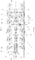
- FIG. 1 shows a rotary plow 1 in side view.
- This is a mounted rotary plow, which is coupled via the mounting frame 14 and its upper and lower coupling points 16, 17 on the three-point hitch of the rotary plow pulling and carrying pull tractor (not shown).
- the rotary plow 1 can be moved from a lowered working position to a raised position for transporting or turning the plow via the three-point linkage of the tractor.
- To turn the plow of the plow frame 3 is over a turning axis 18, which is rotatably mounted in the mounting frame 14, by means of a hydraulic cylinder 15 or other devices by an angle of about 180 ° from a right turn to a left turn position.
- the hydraulic cylinder 15 on the one hand with the mounting frame 14 and at its other end via a lever spaced from the axis 18 to the plow frame 3 hingedly connected.
- a middle position of the plow frame 3 can be locked to the mounting frame 14, for example via a locking pin for transport purposes.
- a plurality of right and left turning plow tools 4, 4 ' are spaced one behind the other.
- the rotary plow 1 is pulled in the direction of travel through the ground.
- the plow tools 4, 4 With direction of travel is the forward direction of the tractor in the working position pulling tractor called.
- the working depth of the plowing tools is determined by the three-point linkage of the tractor and at the rear by the position of the support wheel 2 between the ground surface 7 and the plow frame 3.
- the angle of attack (1/2 ⁇ ) of the pivot arm 6, which is preferably spanned by axis 9 and the plow frame 3 horizontally and symmetrically intersecting central plane 20, the distance of the support wheel 5 to the center plane 20 of the plow frame 3 or or to the ground surface 7 to be changed.
- the angular position can be set as the end position in the working position.
- the stop means 13,13 ' can be designed as oscillating, variable in length threaded spindles, combinations of perforated strip and socket pin, but also as a releasable hydraulic cylinder or other single or double acting actuator.
- the servomotor or hydraulic cylinder can reduce or regulate the swivel speed.
- the support wheel 5 is in working position by lowering the rotary plow 1 on the ground surface 7 and forms the Rad.
- the swivel angle ⁇ which describes the movement of the support wheel in the direction of travel, should not exceed an angle of 160 degrees maximum, so that the support wheel does not swing through to the rear or stops in a vertical position. Pivoting angle ⁇ less than 60 degrees are also less well suited, since the intersection 11 of the axis 9 with the ground surface 7 is then too far away from the wheel contact point 10 and results in an unstable wheel guide.
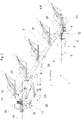
- FIG. 2 shows the rotary plow described above in plan view and in working position.
- the upper and lower links, not shown, of the three-point hydraulic system of the tractor are fastened to the mounting frame 14 at the coupling points 16, 17, 17 'provided for this purpose.
- the plow frame 3 with its attached plow bodies 4, 4 ' can be pivoted about the turning axis 18 from an illustrated, right-turning to a left-turning position, preferably by means of the hydraulic cylinder 15.
- About a link 23 and pin bearings the plow frame 3 is laterally movably connected to the turning axis 18.
- About an adjustment center 22 can be adjusted by means of servomotors or spindles, the front furrow width and the traction point of the plow.
- slide guides for lateral movements of the plow frame are possible.
- the rear end of the plow frame 3 can be pivoted further centered to the axis 18 in order to increase the ground clearance of the excavated plow when turning.
- Another servomotor 25 is provided for swinging the plow frame with parallel adjustment of the cutting width of the individual plow body 4,4 '.
- the Schwenkstützrad 2 is laterally pivotally mounted about the axis 19 on the plow frame.
- a parallel guide in adjusting the cutting width of the individual plow body 4,4 'by pivoting about the axis 21,21' is made possible by a linkage, not shown.
- the pivot arm 6 and the support wheel 5 is rotatably mounted. From this pivotal mounting encompasses the Swivel arm 6, the tire casing of the support wheel 5 and immersed in the middle of the rim. Not visible is rotatably fixed within the rim of a wheel hub on the pivot arm 6 and allows the unwinding of the support wheel 5 on the ground surface.
- the line of action of the pivot arm 6 is almost identical to the axis 9, but may also differ slightly.
- the axis 9 approximately intersects the median plane of the wheel, which is vertical to the axis of the wheel, at the level of the ground surface, this intersection being directed in the direction of travel or to the traction tractor and spaced from the wheel contact point.
- twin or double wheels is conceivable, in which case the axis 9 or the center plane described above is preferably located centrally between these wheels.
- the intersection 11 and the wheel contact point 10 are formed at least approximately centrally between these wheels.
- the pivot axis 8 of the pivot bearing 12 is aligned at least approximately perpendicular to the direction of travel, but can also be further erected against the longitudinal axis of the plow frame 3, to require less pivoting clearance to the ground surface. In this case, the at least approximately vertical alignment of the axis 9 to 8 axis corresponding to the direction of travel to compensate complementary.
- FIG. 3 is the Schwenkstweilrad 2 shown with the rear part of the rotary plow 1 in working position.
- the pivot bearing is laterally pivotally attached to the plow frame 3.
- the Schwenkstweilrad 2 can be aligned in an approximately equal angle parallel to the direction of travel.
- This alignment can be done manually, for example by repositioning a bolt or other adjustment means, or automatically by a parallel guiding device.
- a fixed, deviating from the direction of travel angular position is possible, as far as it can be compensated by the self-steering or tracking properties of the Schwenkstützrades 2.
- the plow body 4, 4 'and their stalk pockets are mounted on the pivot axes 21, 21' rotatable to the pull frame 3. about a parallel guide linkage, the plow body 4, 4 'aligned in the direction of travel and thus a variable cutting width adjustment of the rotary plow 1 and its plow body 4, 4' allows.
- the Schwenkstweilrad 2 and its pivot bearing 12 is coupled with this parallel guide or equal to one of the pivot bearings 21, 21 'attached and also aligned in the direction of travel.
- the Schwenkstweilrad 2 is fixed by a stop means 13 ', which is designed as a tiltable stop spindle, against a stop of the pivot bearings 12.
- the stop means 13 ' falls into an inactive position.
- the Schwenkstweilrad 2 can pivot about the axis 8 in an opposite position in which it is fixed by the opposite stop means 13 in the same function again.
- servomotors such as a releasable hydraulic cylinder or other locking means for fixing the Schwenkstützrades and specification of a working depth of the rotary plow 1 is possible.
- the point of intersection 11 of the axis 9 with the bottom surface forms the imaginary guide point, around which the support wheel 5 lags.
- the support wheel 5 may be a tire with rim, as well as a steel wheel or a roller mold.
- the support wheel can also be provided with a circumferential guide bar or profile, which improves the steering or Abrolleigenschaften on the ground.
Landscapes
- Life Sciences & Earth Sciences (AREA)
- Engineering & Computer Science (AREA)
- Mechanical Engineering (AREA)
- Soil Sciences (AREA)
- Environmental Sciences (AREA)
- Soil Working Implements (AREA)
- Steering-Linkage Mechanisms And Four-Wheel Steering (AREA)
- Handcart (AREA)
Description
- Die Erfindung betrifft ein Schwenkstützrad zum Anbau an einen Pflugrahmen eines Drehpfluges gemäß dem Oberbegriff des Patentanspruches 1.
- Drehpflüge sind zur Tiefenführung ihrer Pflugwerkzeuge meist mit Stützrädern am Pflugrahmen versehen, welche den Abstand des Pflugrahmens zur Bodenoberfläche und somit die Eindringtiefe der Pflugwerkzeuge in den Boden vorgeben. Da der Pflugrahmen in Arbeitsposition schräg zur Fahrtrichtung angewinkelt steht, bieten sich bei der Drehbewegung des Pflugrahmens in Fahrtrichtung schwenkende Stützräder an. Diese benötigen in ihrer Schwenkbewegung einen kleineren Freiraum zum Pflugrahmen als entgegengesetzt der Fahrtrichtung schwenkende Stützräder, wenn diese nicht gerade am Ende des Pflugrahmens angeordnet sind. Grundsätzlich ist der Schwenkarm dieser Stützräder jedoch in Arbeitsstellung nach hinten geneigt, da so gerade bei wechselnden Kräften auf das Stützrad eine Eigenstabilisierung und Selbstausrichtung des Rades erfolgt. Dies verbessert oder ermöglicht erst eine stabile und exakte Seitenführung der Pflugwerkzeuge, wie in der deutschen Offenlegung
DE 30 33 791 dargestellt. Um bei Aufsetzen des Stützrades auf den Boden und Vorwärtsfahrt den Schwenkarm nach hinten zu bewegen, ist dieser mit einer Verlängerung als Erdspieß versehen oder das Stützrad, wie beispielsweise aus derDE 75 38 474 U1 oderDE 25 54 273 C2 , mit einer Bremsvorrichtung oder Ähnlichem ausgestattet. Ein weiteres Pendelstützrad aus dem PatentDE 25 45 009 C3 kann um eine Achse senkrecht verschwenkt werden, um in einer mittleren Transportstellung des Pflugrahmens als frei umlaufendes Transportrad zu dienen. Da diese Stützräder gelegentlich beim Aufsetzen doch nach vorne schwenken und dann ihrer Tiefenführungsfunktion nicht nachkommen, haben sich Stützräder durchgesetzt, welche grundsätzlich entgegen der Fahrtrichtung schwenken, aber einen größeren Schwenkfreiraum relativ zum Pflugrahmen brauchen, welcher dann aber beim Wenden des ausgehobenen Pfluges an Bodenfreiheit fehlt. Das deutsche GebrauchsmusterDE 8532966 U1 schlägt ein Pendelstützrad vor, welches hinter dem Pflugrahmen angeordnet ist. Um ein Grenzpflügen zu ermöglichen, kann das Stützrad um eine vertikale Achse temporär nach vorn geklappt werden. Wie zuvor beschrieben, bedingt diese geschobene Position aber eine instabile Seitenführung
der Pflugwerkzeuge, welche gerade in der Schlussfurche ein schlechtes und ungerades Pflugbild hinterlässt. Dies gilt auch für ein geschobenes Stützrad, welches in dem deutschen GebrauchsmusterDE 299 19 028 U1 vorgeschlagen wird. - Aufgabe der Erfindung ist es, ein Schwenkstützrad bereitzustellen, welches die oben genannten Nachteile vermeidet, die jeweiligen Vorteile jedoch in sich vereint. Diese Aufgabe wird durch die Merkmale des kennzeichnenden Teiles des Anspruches 1 gelöst.
- Durch die Bewegung des Schwenkarmes und somit des Schwenkstützrades ausschließlich in Fahrtrichtung, also in Richtung des ziehenden Fahrzeuges, beschreibt das Schwenkstützrad beim Wenden des Pfluges oder des Pflugrahmens ein Halbkreissegment, welches, seitlich gesehen, im vorderen Bereich vor der Schwenkachse liegt. Das Schwenkstützrad verbleibt somit stets in einer geschobenen Position und kann mit zumindest einem Anschlag in Arbeitsstellung bis zum nächsten Schwenkvorgang festgesetzt werden. Durch die vorzugsweise freie oder zumindest teilweise freie Drehung des Schwenkarmes oder des Schwenkstützrades um die zweite Achse, welche vorzugsweise zumindest annähernd senkrecht zur ersten Achse steht, erhält das Stützrad selbstlenkende Eigenschaften, welche unterschiedliche Stütz- oder Lenkkräfte, die durch die geschobene oder nach vorn gerichtete Anordnung des Schwenkarmes auf das Stützrad oder den Pflugrahmen wirken, aufheben und somit eine exakte Seitenführung des Pfluges ermöglichen.
- In einer erweiterten Erfindungsform ist die Schwenkbewegung des Armes oder des Stützrades um die zweite Achse von einer Mittelstellung nach rechts und links auf einen Schwenkwinkel von jeweils max. 60° begrenzt. Durch diese Begrenzung kann das Stützrad nicht komplett frei, sondern aus der Mittelstellung, welche die optimale Laufrichtung des Stützrades während der Pflugarbeit bildet, nur begrenzt nach links oder rechts auslenken. Gerade beim Aufsetzen des Stützrades bei Beginn der Pflugarbeit spurt das frei gelenkte Rad schnell in die Mittelstellung ein. Die Begrenzung kann durch Anschläge oder mit Federeinrichtungen bewerkstelligt werden. Letztere haben den Vorteil, dass das Stützrad bereits vorausgerichtet in Fahrtrichtung auf den Boden aufsetzt, aber gegen die Federkraft auslenken kann. Beschränkt man, wie zuvor beschrieben, den Drehwinkel des Stützrades auf einen Schwenkwinkel von jeweils max. 20° außerhalb der Mittelstellung, wird die seitliche Lenkbarkeit zwar eingeschränkt, jedoch die seitliche Ausladung des Stützrades vom Pflugrahmen verkürzt. Das Schwenkstützrad kann in seinem Bauraumbedarf noch weiter an den Pflugrahmen heranrücken oder noch weiter hinten am Pflugrahmen angeordnet werden.
- In einer verbesserten Erfindungsform ist der Arm oder die Schwenklagerung in Richtung der zweiten Achse teleskopier- oder verschiebbar ausgeführt. Neben den Schwenkanschlägen um die erste Achse ist hiermit eine weitere, feinjustierbare Verstellmöglichkeit für die Arbeitstiefeneinstellung der Pflugkörper gegeben. Es bietet sich an, den Schwenkarm durch die Schwenklagerung, welche die zweite Achse bildet, hindurch zu schieben oder parallel zu dieser Achse zu verschieben. Dies kann durch ein Teleskoprohr, eine Kulissenführung, aber auch durch eine Mehrgelenkanordnung wie beispielsweise einem Parallelogramm erfolgen.
- In einer anderen Erfindungsform ist das Schwenkstützrad, die Schwenklagerung oder der Arm um eine dritte Achse, welche annähernd senkrecht zur Bodenoberfläche oder zur Symmetrieebene des Pflugrahmens angeordnet ist, schwenkbar gelagert. Durch diese Bauart kann die Vorrichtung bei unterschiedlichen Winkelstellungen des Pflugrahmens zur Fahrtrichtung, von oben betrachtet, in ihrem Winkel zum Pflugrahmen verstellt werden.
- In einer einfachen Erfindungsausführung entspricht die dritte Achse, um welche das Schwenkstützrad, die Schwenklagerung oder der Arm schwenkbar gelagert ist, der Schwenkachse eines Pflugkörpers oder Pflugkörperpaares. Durch diese Bauart kann die Schwenklagerung des Pflugkörpers zur Verstellung seiner Schnittbreite als Schwenklager für Winkeleinstellung des Schwenkstützrades, von oben betrachtet, zum Pflugrahmen genutzt werden. Die Vorrichtung bleibt hierdurch immer parallel zum Pflugwerkzeug und somit zur Fahrtrichtung ausgerichtet.
- In einer besonders betriebssicheren Ausführung der Erfindung sind Mittel, welche die Schwenkgeschwindigkeit des Schwenkstützrades um die erste und/oder zweite Achse begrenzen, am Arm oder am Pflugrahmen angeordnet. Beispielsweise durch Dämpfungszylinder, Reibscheiben oder andere geeignete Elemente wird die Dynamik, welche beim Drehen des gesamten Pflugrahmens und somit beim Schwenken des Stützrades auftreten, entschärft.
- In einer komfortablen Erfindungsausführung ist die Schwenkbewegung des Schwenkstützrades um die erste und/oder zweite Achse durch zumindest eine Fremdkrafteinrichtung unterstützend oder blockierend ausgebildet. Beispielsweise kann der Schwenkvorgang des Stützrades beim Drehen des Pfluges durch einen Hydraulikzylinder zeitgesteuert und definiert ausgeführt werden. Auch eine Fernbetätigung beispielsweise von Hydraulikzylindern oder anderen Stellmotoren ermöglicht eine komfortable Arbeitstiefeneinstellung der Pflugkörper während der Fahrt durch Veränderung des Schwenkwinkels des Schwenkstützrades um die erste Achse.
- In einer anderen Erfindungsform ist die Bewegung des Schwenkstützrades oder des Armes um die zweite Achse mittels Arretiermittel in einer zur mittleren Position um 90 Grad verdrehten Stellung festsetzbar ausgebildet. Durch diese Anordnung kann das Stützrad um die zweite Achse in eine Lage parallel zur Symmetrieebene des Pflugrahmens festgesetzt werden. Bei einer mittleren Transportposition des Pflugrahmens kann das Schwenkstützrad um die erste Achse nachlaufen und einen Teil des Pfluggewichtes bei Straßenfahrt tragen, wenn die Schwenkwinkelbegrenzung um die erste Achse außer Betrieb gesetzt ist.
- In einer bevorzugten Form der Erfindung ist das Schwenkstützrades in der Nähe des letzten oder des vorletzten Pflugkörpers befestigt. Je weiter das Schwenkstützrad vom Zugtraktor entfernt ist, desto mehr Pfluggewicht kann- statt über das Stützrad - vom Dreipunktgestänge des Zugtraktors traktionsverbessernd aufgenommen werden, indem die Hinterachse des Traktors stärker belastet wird. Gerade bei weit nach hinten ausladenden Pflügen wie vielscharigen Anbaudrehpflügen oder Karrendrehpflügen mit beweglichem Hinterteil bietet sich diese Stützradanordnung an.
- Die Erfindung zeichnet sich insbesondere dadurch aus, dass durch Verwendung eines geschobenen Schwenkstützrades erforderlicher Bauraum und Schwenkfreiraum für ein Stützrad eines Pfluges sowohl gegenüber dem Pflugrahmen und seinen Anbauteilen als auch gegenüber der Bodenoberfläche während des Schwenk- oder Wendevorganges verringert werden kann. Auch das Grenzpflügen nahe Zaun- oder Weggrenzen wird über das weniger seitlich zur Fahrtrichtung ausladende, geschobene Stützrad erleichtert. Durch die geringere seitliche Ausladung des Schwenkstützrades können zudem Hebel, Arme, Halterungen und Lagerungen kleiner, leichter und kostengünstiger ausgelegt werden.
- Weitere Einzelheiten und Vorteile des Erfindungsgegenstandes ergeben sich aus der nachfolgenden Beschreibung und den zugehörigen Zeichnungen, in denen ein Ausführungsbeispiel mit den dazu notwendigen Einzelheiten und Einzelteilen dargestellt ist. Es zeigen:
-
Fig.1 einen Anbaudrehpflug in Seitenansicht von links -
Fig.2 einen Anbaudrehpflug in Draufsicht -
Fig.3 den hinteren Bereich eines Anbaudrehpfluges mit Schwenkstützrad in perspektivischer Darstellung -
Figur 1 zeigt einen Drehpflug 1 in Seitenansicht. Hierbei handelt es sich um einen Anbaudrehpflug, welcher über den Anbaurahmen 14 sowie dessen obere und untere Koppelpunkte 16, 17 am Dreipunktkraftheber eines den Drehpflug ziehenden und tragenden Zugtraktors (nicht dargestellt) gekoppelt ist. Über den Dreipunktkraftheber des Zugtraktors kann der Drehpflug 1 von einer abgesenkten Arbeitsstellung in eine ausgehobene Stellung zum Transport oder zum Wenden des Pfluges bewegt werden. Zum Wenden des Pfluges ist der Pflugrahmen 3 über eine Wendeachse 18, welche drehbar im Anbaurahmen 14 gelagert ist, mittels eines Hydraulikzylinders 15 oder anderer Vorrichtungen um einen Winkel von etwa 180° von einer rechtswendenden in eine linkswendende Position schwenkbar. Hierfür ist der Hydraulikzylinder 15 einerseits mit dem Anbaurahmen 14 und an seinem anderen Ende über einen Hebel beabstandet zu Achse 18 mit dem Pflugrahmen 3 gelenkig verbunden. In einer mittleren Position kann der Pflugrahmen 3 mit dem Anbaurahmen 14 beispielsweise über einen Steckbolzen zu Transportzwecken verriegelt werden. An dem Pflugrahmen 3 sind hintereinander beabstandet mehrere rechts- und linkswendende Pflugwerkzeuge 4, 4' befestigt. Jeweils ein rechts- und ein linkswendendes Pflugwerkzeug 4, 4' bilden über die Mittelebene 20 des Pflugrahmens 4 eine vorzugsweise symmetrisch aufgebaute Befestigungseinheit. In Arbeitsstellung wird der Drehpflug 1 in Fahrtrichtung durch den Boden gezogen. Mit Fahrtrichtung ist die Vorwärtsfahrtrichtung des den Pflug in Arbeitsstellung ziehenden Traktors bezeichnet. Dabei schneiden die Pflugwerkzeuge 4, 4' einen Teil des Bodens unterhalb der Bodenoberfläche 7 ab und wenden diesen zur Seite. Im Vorderen Bereich wird die Arbeitstiefe der Pflugwerkzeuge durch den Dreipunktkraftheber des Zugtraktors und im hinteren Bereich durch die Stellung des Stützrades 2 zwischen Bodenoberfläche 7 und Pflugrahmen 3 vorgegeben. Durch die Änderung des Anstellwinkels (1/2 α) des Schwenkarmes 6 , welcher durch Achse 9 und der den Pflugrahmen 3 vorzugsweise horizontal und symmetrisch schneidende Mittelebene 20 aufgespannt wird, kann der Abstand des Stützrades 5 zur Mittelebene 20 des Pflugrahmens 3 oder beziehungsweise zur Bodenoberfläche 7 verändert werden. Hierdurch ändert sich die maximale Arbeitstiefe der Pflugkörper 4,4' im Boden. Durch die Anschlagmittel 13,13' kann die Winkelstellung als Endlage in Arbeitsposition festgesetzt werden. Die Anschlagmittel 13,13' können als pendelnde, in der Länge veränderbare Gewindespindeln, Kombinationen aus Lochleiste und Steckbolzen, ebenso aber auch als entsperrbarer Hydraulikzylinder oder anderer einfach oder doppelt wirkender Stellmotor ausgeführt sein. Der Stellmotor oder Hydraulikzylinder kann zugleich die Schwenkgeschwindigkeit reduzieren oder regeln. Das Stützrad 5 setzt in Arbeitsstellung durch Absenken des Drehpfluges 1 auf die Bodenoberfläche 7 auf und bildet den Radkontaktpunkt 10. Der Schnittpunkt 11, welche durch die nach vorne geneigte, verlängerte Lenkachse 9 und der Bodenoberfläche 7 gebildet wird, ist in Fahrtrichtung vom Radaufstandspunkt 10 beabstandet und bildet einen Führungspunkt, nach welchem das Rad 5 selbstlenkend nachläuft. Der Schwenkwinkel α, welcher die Bewegung des Stützrades in Fahrtrichtung beschreibt, soll einen Winkel von maximal 160 Grad nicht überschreiten, damit das Stützrad nicht nach hinten durchschwenkt oder in einer senkrechten Position stehen bleibt. Schwenkwinkel α kleiner 60 Grad sind ebenfalls weniger gut geeignet, da der Schnittpunkt 11 der Achse 9 mit der Bodenoberfläche 7 dann zu weit nach vorne von dem Radkontaktpunkt 10 entfernt liegt und eine instabile Radführung zur Folge hat. -
Figur 2 zeigt den zuvor beschriebenen Drehpflug in Draufsicht und in Arbeitsstellung. Die nicht dargestellten Ober- und Unterlenker der Dreipunkthydraulik des Traktors werden am Anbaurahmen 14 an den dafür vorgesehenen Koppelpunkten 16,17, 17' befestigt. Wie zuvor beschrieben, kann der Pflugrahmen 3 mit seinen daran befestigten Pflugkörpern 4, 4' um die Wendeachse 18 von einer dargestellten, rechtswendenden in eine linkswendende Position vorzugsweise mittels des Hydraulikzylinders 15 verschwenkt werden. Über einen Lenker 23 sowie Bolzenlagerungen ist der Pflugrahmen 3 seitlich beweglich mit der Wendeachse 18 verbunden. Über ein Einstellcenter 22 kann mittels Stellmotoren oder Spindeln die Vorderfurchenbreite und der Zugpunkt des Pfluges eingestellt werden. Auch Schlittenführungen zur seitlichen Bewegungen des Pflugrahmens sind möglich. Mittels eines Einschwenkzylinders 24 kann das hintere Ende des Pflugrahmens 3 weiter mittig zur Achse 18 eingeschwenkt werden, um die Bodenfreiheit des ausgehobenen Pfluges beim Wenden zu erhöhen. Ein weiterer Stellmotor 25 ist zum Ausschwenken des Pflugrahmens bei paralleler Verstellung des Schnittbreite der einzelnen Pflugkörper 4,4' vorgesehen. Im hinteren Bereich des Pflugrahmens 3 ist das Schwenkstützrad 2 seitlich schwenkbar um die Achse 19 am Pflugrahmen befestigt. Eine Parallelführung bei Verstellung der Schnittbreite der einzelnen Pflugkörper 4,4' durch Schwenken um die Achse 21,21' ist durch ein nicht dargestelltes Gestänge ermöglicht. Um die Achse 9, welche schräg zum Boden und nach vorne zeigt, ist der Schwenkarm 6 und das Stützrad 5 drehbar gelagert. Von dieser Schwenklagerung umgreift der Schwenkarm 6 den Reifenmantel des Stützrades 5 und taucht mittig in dessen Felge ein. Nicht sichtbar ist innerhalb der Felge einer Radnabe drehbar am Schwenkarm 6 gefestigt und ermöglicht das Abrollen des Stützrades 5 auf der Bodenoberfläche. Die Wirklinie des Schwenkarmes 6 liegt nahezu mit der Achse 9 überein, kann aber auch geringfügig davon abweichen. Wichtig ist, dass die Achse 9 ungefähr die Mittelebene des Rades, welche vertikal zur Laufachse des Rades steht, in Höhe der Bodenoberfläche schneidet, wobei dieser Schnittpunkt in Fahrtrichtung oder zum Zugtraktor gerichtet und beabstandet zum Radkontaktpunkt liegt. Auch die Verwendung von Zwillings- oder Doppelrädern ist denkbar, wobei dann die Achse 9 bzw. die zuvor beschriebene Mittelebene vorzugsweise mittig zwischen diesen Rädern liegt. Ebenso werden der Schnittpunkt 11 und der Radkontaktpunkt 10 zumindest annähernd mittig zwischen diesen Rädern gebildet. Die Schwenkachse 8 der Schwenklagerung 12 ist zumindest annähernd senkrecht zur Fahrtrichtung ausgerichtet, kann aber auch weiter gegen die Längsachse des Pflugrahmens 3 aufgerichtet werden, um weniger Schwenkfreiraum zur Bodenoberfläche zu benötigen. In diesem Falle ist die zumindest annähernd senkrechte Ausrichtung der Achse 9 zu Achse 8 entsprechend der Fahrtrichtung komplementär zu kompensieren. - In
Figur 3 ist das Schwenkstützrad 2 mit dem hinteren Teil des Drehpfluges 1 in Arbeitsstellung dargestellt. Um die Achse 19 ist die Schwenklagerung seitlich schwenkbar zum Pflugrahmen 3 befestigt. Entsprechend der Winkelstellung des Pflugrahmens 3 zur Fahrtrichtung kann das Schwenkstützrad 2 in einem annähernd gleichen Winkel parallel zur Fahrtrichtung ausgerichtet werden. Diese Ausrichtung kann manuell, beispielsweise durch Umstecken eines Bolzens oder anderer Einstellmittel, oder automatisch durch eine Parallelführeinrichtung erfolgen. In gewissem Maße ist auch eine fixe, von der Fahrtrichtung abweichende Winkelstellung möglich, soweit sie durch die Selbstlenk- oder Nachlaufeigenschaften des Schwenkstützrades 2 kompensiert werden kann. Dies gilt für alle beschriebenen Achsausrichtungen, welche die Funktion des Schwenkstützrades 2 beeinflussen. Die Pflugkörper 4, 4' und ihre Halmtaschen sind über die Schwenkachsen 21, 21' drehbar zum Zugrahmen 3 gelagert. Über ein Parallelführgestänge werden die Pflugkörper 4, 4' in Fahrtrichtung ausgerichtet und somit eine variable Schnittbreitenverstellung des Drehpfluges 1 bzw. seiner Pflug Körper 4, 4' ermöglicht. In idealer Weise wird das Schwenkstützrad 2 bzw. seine Schwenklagerung 12 mit dieser Parallelführung gekoppelt oder gleich an einer der Schwenklagerungen 21, 21' befestigt und ebenfalls in Fahrtrichtung ausgerichtet. In der gezeigten Arbeitsstellung wird das Schwenkstützrad 2 durch ein Anschlagmittel 13', welche als kippbare Anschlagspindel ausgeführt ist, gegen einen Anschlag der Schwenklagerungen 12 fixiert. Beim Wenden des Pfluges fällt das Anschlagmittel 13' in eine inaktive Stellung. Das Schwenkstützrad 2 kann um die Achse 8 in eine gegenüberliegende Stellung schwenken, in welcher es durch das gegenüberliegende Anschlagmittel 13 in gleicher Funktion wieder fixiert wird. Ebenso ist der Einsatz von Stellmotoren, beispielsweise einem entsperrbaren Hydraulikzylinder oder andere Arretierungsmittel zur Festsetzung des Schwenkstützrades und Vorgabe einer Arbeitstiefe des Drehpfluges 1 möglich. Die seitlichen Kräfte, welche in Arbeitsstellung des Drehpfluges 1 am Radkontaktpunkt 10 auf das Stützrad 51 wirken, richten dieses mit einem wirksamen Hebelabstand, welcher zwischen Achse 9 und Radkontaktpunkt 10 gebildet wird, selbstlenkend in Fahrtrichtung aus. Der Schnittpunkt 11 der Achse 9 mit der Bodenoberfläche bildet dabei den gedachten Führungspunkt, um welchen das Stützrad 5 nachläuft. Das Stützrad 5 kann ein Reifen mit Felge sein, ebenso aber auch ein Stahlrad oder eine Walzenform. Das Stützrad kann zudem mit einem umlaufenden Führungssteg oder Profil versehen sein, welches die Lenk- oder Abrolleigenschaften auf dem Boden verbessert.BEZUGSZEICHENLISTE 1 Drehpflug 2 Schwenkstützrad 3 Pflugrahmen 4 Pflugwerkzeug, Plfugkörper 5 Stützrad 6 Arm, Schwenkarm 7 Boden, Bodenoberfläche 8 Achse, Schwenkachse 9 Achse, Lenkachse 10 Radkontaktpunkt 11 Schnittpunkt 12 Schwenklagerung 13 Anschlagmittel 14 Anbaurahmen 15 Hydraulikzylinder 16 Koppelpunkt 17 Koppelpunkt 18 Wendeachse 19 Achse, Schwenkachse 20 Mittelebene 21 Achse, Schwenkachse 22 Einstellcenter 23 Lenker 24 Einschwenkzylinder 25 Stellmotor
Claims (10)
- Drehpflug (1) mit Schwenkstützrad (2) zum Anbau an einen Pflugrahmen (3) des Drehpfluges (1), wobei der Pflugrahmen (3) mit mehreren, daran paarweise gegenüberliegend befestigten, spiegelbildlichen Pflugkörpern (4,4') durch eine Drehung von nahezu 180 Grad von einer linkswendenden in eine rechtswendende Position gebracht werden kann, wobei am Pflugrahmen (3) zumindest ein Stützrad (5) zur Tiefenbegrenzung der Pflugkörper (4,4') über einen Arm (6) schwenkbar angebracht ist, wobei der Arm (6) zur Lagerung des Stützrades (5) um eine erste, zumindest annähernd parallel zur Bodenoberfläche (7) oder zumindest annähernd durch die Mittelebene (20) des Pflugrahmens (3) verlaufende Achse (8) bei der Drehung des Pflugrahmens (3) in seinem Schwenkwinkel begrenzt rotiert und nach dieser Rotation durch eine weitere Vorrichtung in eine der Pflugausrichtung entsprechende, jeweilige Arbeitsstellung arretiert werden kann, wobei die Bewegung des Armes (6) um die erste Achse (8) in Fahrtrichtung oder nach vorn gerichtet erfolgt und einen max. Schwenkwinkel (α) von 160 Grad beschreibt, wobei eine zweite Achse (9), welche zumindest annähernd durch eine senkrecht zur Bodenoberfläche (7) und zumindest annähernd parallel zur Fahrtrichtung verlaufenden Ebene angeordnet ist, wobei die zweite, nach vorne geneigte Achse (9) vor dem Radkontaktpunkt (10) mit der Bodenoberfläche (7) einen Schnittpunkt (11) bildend angeordnet ist, welcher den gedachten Führungspunkt bildet, um welchen das Stützrad (5) nachläuft,
dadurch gekennzeichnet, dass der Arm (6) oder das Stützrad (5) um die zweite Achse (9) drehbar gelagert ist. - Drehpflug mit Schwenkstützrad nach Anspruch 1,
dadurch gekennzeichnet,
dass die Schwenkbewegung des Armes (6) oder des Stützrades (5) um die zweite Achse (9) von einer Mittelstellung nach rechts und links auf einen Schwenkwinkel von jeweils max. 60 Grad begrenzt ist. - Drehpflug mit Schwenkstützrad nach Anspruch 2,
dadurch gekennzeichnet,
dass die Schwenkbewegung um die zweite Achse (9) von einer Mittelstellung nach rechts und links auf einen Schwenkwinkel von jeweils max. 20 Grad begrenzt ist. - Drehpflug mit Schwenkstützrad nach Anspruch 1, 2 oder 3,
dadurch gekennzeichnet,
dass der Arm (6) oder die Schwenklagerung (12) in Richtung der zweiten Achse (9) teleskopier- oder verschiebbar ausgeführt ist. - Drehpflug mit Schwenkstützrad nach zumindest einem der vorstehenden Ansprüche,
dadurch gekennzeichnet,
dass das Schwenkstützrad (2), die Schwenklagerung (12) oder der Arm (6) um eine dritte Achse (19), welche annähernd senkrecht zur Bodenoberfläche (7) oder zur Symmetrieebene (20) des Pflugrahmens (4) angeordnet ist, schwenkbar gelagert ist. - Drehpflug mit Schwenkstützrad nach zumindest einem der vorstehenden Ansprüche,
dadurch gekennzeichnet,
dass die dritte Achse (19), um welche das Schwenkstützrad (2), die Schwenklagerung (12) oder der Arm (6) schwenkbar gelagert ist, der Schwenkachse (21, 21') eines Pflugkörpers (4,4') oder Pflugkörperpaares entspricht. - Drehpflug mit Schwenkstützrad nach zumindest einem der vorstehenden Ansprüche,
dadurch gekennzeichnet,
dass Mittel, welche die Schwenkgeschwindigkeit des Schwenkstützrades (2) oder des Armes (6) um die erste und/oder zweite Achse (8,9) begrenzen, am Arm (6) oder am Pflugrahmen (3) angeordnet sind. - Drehpflug mit Schwenkstützrad nach zumindest einem der vorstehenden Ansprüche,
dadurch gekennzeichnet,
dass die Schwenkbewegung des Schwenkstützrades (2) um die erste und/oder zweite Achse (8,9) durch zumindest eine Fremdkrafteinrichtung unterstützend oder blockierend ausgebildet ist. - Drehpflug mit Schwenkstützrad nach zumindest einem der vorstehenden Ansprüche,
dadurch gekennzeichnet,
dass die Bewegung des Schwenkstützrades (2) oder des Armes (6) um die zweite Achse (9) mittels Arretiermittel in einer zur mittleren Position um 90 Grad verdrehten Stellung festsetzbar ausgebildet ist. - Drehpflug mit Schwenkstützrad nach zumindest einem der vorstehenden Ansprüche,
dadurch gekennzeichnet,
dass das Schwenkstützrades (2) in der Nähe des letzten oder des vorletzten Pflugkörpers (4,4') befestigt ist.
Priority Applications (1)
| Application Number | Priority Date | Filing Date | Title |
|---|---|---|---|
| PL15770436T PL3166379T3 (pl) | 2014-07-09 | 2015-07-09 | Pług obracalny z przechylnym kołem podporowym do montażu na ramie pługa |
Applications Claiming Priority (2)
| Application Number | Priority Date | Filing Date | Title |
|---|---|---|---|
| DE102014109605.3A DE102014109605B4 (de) | 2014-07-09 | 2014-07-09 | Schwenkstützrad zum Anbau an einen Pflugrahmen |
| PCT/DE2015/100292 WO2016004926A1 (de) | 2014-07-09 | 2015-07-09 | Schwenkstützrad zum anbau an einen pflugrahmen |
Publications (2)
| Publication Number | Publication Date |
|---|---|
| EP3166379A1 EP3166379A1 (de) | 2017-05-17 |
| EP3166379B1 true EP3166379B1 (de) | 2018-10-03 |
Family
ID=54196739
Family Applications (1)
| Application Number | Title | Priority Date | Filing Date |
|---|---|---|---|
| EP15770436.2A Active EP3166379B1 (de) | 2014-07-09 | 2015-07-09 | Drehpflug mit schwenkstützrad zum anbau an den pflugrahmen |
Country Status (12)
| Country | Link |
|---|---|
| US (1) | US10172271B2 (de) |
| EP (1) | EP3166379B1 (de) |
| JP (1) | JP6487526B2 (de) |
| CN (1) | CN106793752B (de) |
| CA (1) | CA2954406C (de) |
| DE (1) | DE102014109605B4 (de) |
| DK (1) | DK3166379T3 (de) |
| EA (1) | EA032237B1 (de) |
| HU (1) | HUE040535T2 (de) |
| PL (1) | PL3166379T3 (de) |
| UA (1) | UA118292C2 (de) |
| WO (1) | WO2016004926A1 (de) |
Families Citing this family (8)
| Publication number | Priority date | Publication date | Assignee | Title |
|---|---|---|---|---|
| DK3437446T3 (da) * | 2017-08-03 | 2020-07-20 | Kverneland Group Operations Norway As | Fjernjustering af skimmer til en muldpladeplov |
| EP3729938B1 (de) * | 2019-04-25 | 2025-01-22 | Overum Industries AB | Landwirtschaftlicher pflug und verfahren zum betrieb |
| CN211047771U (zh) * | 2019-10-28 | 2020-07-21 | 李殿奎 | 无级摆动翻转犁 |
| DE102019217245B3 (de) * | 2019-11-07 | 2020-12-24 | Franz-Ferdinand Huber | Pflugmodul mit lochplatte |
| IT202000015928A1 (it) * | 2020-07-01 | 2022-01-01 | Maschio Gaspardo Spa | Aratro reversibile portato |
| IT202000015910A1 (it) * | 2020-07-01 | 2022-01-01 | Maschio Gaspardo Spa | Aratro reversibile portato |
| EP4074583B1 (de) | 2021-04-16 | 2024-12-04 | MARMIX GmbH & Co. KG | Hilfsradvorrichtung für zugmaschinen und zugmaschinensystem |
| DE102021126501A1 (de) | 2021-10-13 | 2023-04-13 | Pöttinger Landtechnik Gmbh | Anbaudrehpflug |
Citations (1)
| Publication number | Priority date | Publication date | Assignee | Title |
|---|---|---|---|---|
| DE29919028U1 (de) * | 1999-10-29 | 1999-12-30 | Gebr. Pöttinger GmbH, 86899 Landsberg | Drehpflug mit vorlaufendem Stützrad |
Family Cites Families (31)
| Publication number | Priority date | Publication date | Assignee | Title |
|---|---|---|---|---|
| GB752103A (en) * | 1953-02-02 | 1956-07-04 | Roy L Chandler | Plow tail wheel construction |
| US2869653A (en) * | 1955-11-14 | 1959-01-20 | Int Harvester Co | Gauge wheel for two-way plow |
| US3087556A (en) * | 1956-02-09 | 1963-04-30 | Harry A Pursche | Two way plow construction with means to limit rotation of carrier |
| US3106252A (en) * | 1961-10-25 | 1963-10-08 | Allis Chalmers Mfg Co | Rear gauge wheel for two-way plows |
| FR1393243A (fr) * | 1962-05-18 | 1965-03-26 | Charrue traînée par tracteur | |
| US3219125A (en) * | 1963-08-02 | 1965-11-23 | Case Co J I | Agricultural implement |
| US3356161A (en) * | 1965-01-21 | 1967-12-05 | Allis Chalmers Mfg Co | Tail wheel reversing mechanism for spinner plows |
| US3428135A (en) * | 1966-03-04 | 1969-02-18 | Massey Ferguson Inc | Turnover plow |
| US3448815A (en) * | 1966-10-17 | 1969-06-10 | Int Harvester Co | Implement supporting wheel |
| JPS4528242Y1 (de) * | 1967-03-19 | 1970-10-30 | ||
| US3532172A (en) * | 1968-05-09 | 1970-10-06 | Massey Ferguson Inc | Semi-mounted plow with caster wheel that can be tilted and locked for plowing |
| US3589451A (en) * | 1968-09-27 | 1971-06-29 | Case Co J I | Hitch mechanism |
| DE2545009C3 (de) | 1975-10-08 | 1978-04-06 | Rabewerk Heinrich Clausing, 4515 Bad Essen | Drehpflug mit einem Pendelstützrad |
| DE7538474U (de) | 1975-12-03 | 1980-02-28 | Rabewerk Heinrich Clausing, 4515 Bad Essen | Pendelstuetzrad fuer drehpfluege |
| DE2554273C2 (de) | 1975-12-03 | 1983-04-21 | Rabewerk Heinrich Clausing, 4515 Bad Essen | Pendelstützrad für Drehpflüge |
| JPS52153602U (de) * | 1976-05-15 | 1977-11-21 | ||
| US4098346A (en) * | 1976-10-01 | 1978-07-04 | Deere & Company | Steering for plow with adjustable plow bottoms |
| US4186806A (en) | 1977-09-06 | 1980-02-05 | International Harvester Company | Plow system |
| DE3033791C2 (de) | 1980-09-09 | 1985-12-12 | Rabewerk Heinrich Clausing, 4515 Bad Essen | Pendelstütz- und Nachlaufrad für Drehpflüge |
| EP0181947B1 (de) | 1984-11-10 | 1988-12-28 | Rabewerk Heinrich Clausing | Pendelstützrad für Drehpflüge |
| JPH0693805B2 (ja) | 1984-10-25 | 1994-11-24 | スガノ農機株式会社 | リバーシブルプラウのケージホイール装置 |
| JPS6189214U (de) * | 1984-11-19 | 1986-06-10 | ||
| US4691785A (en) * | 1985-03-18 | 1987-09-08 | Post Brothers Construction Co. | Reversible plow and carriage |
| DE8532966U1 (de) | 1985-11-23 | 1986-01-09 | H. Niemeyer Söhne GmbH & Co KG, 4446 Hörstel | Drehpflug mit Stützrad |
| FR2598056B1 (fr) * | 1986-05-05 | 1988-12-02 | Huard Ucf | Dispositif de controle de la profondeur de labour pour une charrue reversible |
| GB9213883D0 (en) * | 1992-06-30 | 1992-08-12 | Kverneland Klepp As | Combined depth/transport wheel for reversible plough |
| JPH1118501A (ja) * | 1997-07-03 | 1999-01-26 | Sugano Noki Kk | プラウ作業機 |
| CN2741333Y (zh) * | 2004-10-14 | 2005-11-23 | 黑山县机械制造有限公司 | 高速调幅液压翻转犁 |
| PL2408289T3 (pl) | 2009-03-21 | 2013-10-31 | Lemken Gmbh & Co Kg | Pług obracalny z ulepszonym mechanizmem obracającym |
| UA71069U (en) | 2012-04-17 | 2012-06-25 | Общество С Ограниченной Ответственностью "Украинское Конструкторское Бюро Трансмиссий И Шасси" | Soil-cultivating unit |
| DE102013106783B4 (de) * | 2013-06-28 | 2017-08-24 | Lemken Gmbh & Co. Kg | Schwenkstützrad für einen Drehpflug |
-
2014
- 2014-07-09 DE DE102014109605.3A patent/DE102014109605B4/de not_active Expired - Fee Related
-
2015
- 2015-07-09 HU HUE15770436A patent/HUE040535T2/hu unknown
- 2015-07-09 WO PCT/DE2015/100292 patent/WO2016004926A1/de not_active Ceased
- 2015-07-09 PL PL15770436T patent/PL3166379T3/pl unknown
- 2015-07-09 CA CA2954406A patent/CA2954406C/en active Active
- 2015-07-09 EA EA201790132A patent/EA032237B1/ru not_active IP Right Cessation
- 2015-07-09 CN CN201580037337.2A patent/CN106793752B/zh not_active Expired - Fee Related
- 2015-07-09 US US15/324,732 patent/US10172271B2/en active Active
- 2015-07-09 EP EP15770436.2A patent/EP3166379B1/de active Active
- 2015-07-09 DK DK15770436.2T patent/DK3166379T3/en active
- 2015-07-09 JP JP2017500382A patent/JP6487526B2/ja not_active Expired - Fee Related
- 2015-09-07 UA UAA201701161A patent/UA118292C2/uk unknown
Patent Citations (1)
| Publication number | Priority date | Publication date | Assignee | Title |
|---|---|---|---|---|
| DE29919028U1 (de) * | 1999-10-29 | 1999-12-30 | Gebr. Pöttinger GmbH, 86899 Landsberg | Drehpflug mit vorlaufendem Stützrad |
Also Published As
| Publication number | Publication date |
|---|---|
| JP2017520258A (ja) | 2017-07-27 |
| CN106793752A (zh) | 2017-05-31 |
| EP3166379A1 (de) | 2017-05-17 |
| WO2016004926A1 (de) | 2016-01-14 |
| PL3166379T3 (pl) | 2019-04-30 |
| EA032237B1 (ru) | 2019-04-30 |
| CA2954406A1 (en) | 2016-01-14 |
| US20170202127A1 (en) | 2017-07-20 |
| DE102014109605B4 (de) | 2018-05-30 |
| CN106793752B (zh) | 2019-07-23 |
| JP6487526B2 (ja) | 2019-03-20 |
| US10172271B2 (en) | 2019-01-08 |
| HUE040535T2 (hu) | 2019-03-28 |
| UA118292C2 (uk) | 2018-12-26 |
| EA201790132A1 (ru) | 2017-05-31 |
| DE102014109605A1 (de) | 2016-01-14 |
| CA2954406C (en) | 2020-09-01 |
| DK3166379T3 (en) | 2019-01-28 |
Similar Documents
| Publication | Publication Date | Title |
|---|---|---|
| EP3166379B1 (de) | Drehpflug mit schwenkstützrad zum anbau an den pflugrahmen | |
| DE2759374C2 (de) | Pflug, insbesondere Aufsattelpflug | |
| EP2793542B1 (de) | Integriertes bodenbearbeitungsgerät für drehpflüge | |
| WO2014067508A1 (de) | Anbaudrehpflug mit einschwenkbegrenzung | |
| EP3302016B1 (de) | Aufsattelpflug | |
| DE3523632A1 (de) | Pflug | |
| WO2023174490A1 (de) | Landwirtschaftliches arbeitsgerät | |
| DE3530107C2 (de) | Pflug | |
| EP2220922B1 (de) | Pflug | |
| DE2639608C2 (de) | ||
| EP1625781B1 (de) | Anbaudrehpflug | |
| DE1296860B (de) | Kehrpflug, insbesondere Aufsattelscharkehrpflug mit mindestens einem Stuetzrad | |
| DE29600075U1 (de) | Pflug | |
| EP2050323B1 (de) | Aufsatteldrehpflug | |
| DE4031503C2 (de) | Aufsatteldrehpflug | |
| EP2656707B1 (de) | Pflug mit Stützrad | |
| EP4201166B1 (de) | Bodenbearbeitungsgerät | |
| DE2618892C3 (de) | Anhänge-Drehpflug für neben der Vorfurche fahrende Schlepper | |
| DE2616241C2 (de) | AnhängevoUdrehpflug für neben der Vorfurche fahrende Schlepper | |
| EP0783831B1 (de) | Wendepflug mit Anbauteil | |
| DE60110930T2 (de) | Mehrscharpflug mit variabler arbeitsbreite | |
| EP2974580B1 (de) | Drehpflug | |
| DE102012103667A1 (de) | Tiefenführungsrad | |
| EP1033070B1 (de) | Anbaupflug mit Einstellzentrum | |
| DE4225068A1 (de) | Pflug mit einem am Pflugrahmen angebrachten Ausleger |
Legal Events
| Date | Code | Title | Description |
|---|---|---|---|
| STAA | Information on the status of an ep patent application or granted ep patent |
Free format text: STATUS: THE INTERNATIONAL PUBLICATION HAS BEEN MADE |
|
| PUAI | Public reference made under article 153(3) epc to a published international application that has entered the european phase |
Free format text: ORIGINAL CODE: 0009012 |
|
| STAA | Information on the status of an ep patent application or granted ep patent |
Free format text: STATUS: REQUEST FOR EXAMINATION WAS MADE |
|
| 17P | Request for examination filed |
Effective date: 20170209 |
|
| AK | Designated contracting states |
Kind code of ref document: A1 Designated state(s): AL AT BE BG CH CY CZ DE DK EE ES FI FR GB GR HR HU IE IS IT LI LT LU LV MC MK MT NL NO PL PT RO RS SE SI SK SM TR |
|
| AX | Request for extension of the european patent |
Extension state: BA ME |
|
| DAV | Request for validation of the european patent (deleted) | ||
| DAX | Request for extension of the european patent (deleted) | ||
| GRAP | Despatch of communication of intention to grant a patent |
Free format text: ORIGINAL CODE: EPIDOSNIGR1 |
|
| STAA | Information on the status of an ep patent application or granted ep patent |
Free format text: STATUS: GRANT OF PATENT IS INTENDED |
|
| INTG | Intention to grant announced |
Effective date: 20180601 |
|
| GRAS | Grant fee paid |
Free format text: ORIGINAL CODE: EPIDOSNIGR3 |
|
| GRAA | (expected) grant |
Free format text: ORIGINAL CODE: 0009210 |
|
| STAA | Information on the status of an ep patent application or granted ep patent |
Free format text: STATUS: THE PATENT HAS BEEN GRANTED |
|
| AK | Designated contracting states |
Kind code of ref document: B1 Designated state(s): AL AT BE BG CH CY CZ DE DK EE ES FI FR GB GR HR HU IE IS IT LI LT LU LV MC MK MT NL NO PL PT RO RS SE SI SK SM TR |
|
| REG | Reference to a national code |
Ref country code: GB Ref legal event code: FG4D Free format text: NOT ENGLISH |
|
| REG | Reference to a national code |
Ref country code: CH Ref legal event code: EP Ref country code: AT Ref legal event code: REF Ref document number: 1047598 Country of ref document: AT Kind code of ref document: T Effective date: 20181015 |
|
| REG | Reference to a national code |
Ref country code: IE Ref legal event code: FG4D Free format text: LANGUAGE OF EP DOCUMENT: GERMAN Ref country code: DE Ref legal event code: R096 Ref document number: 502015006258 Country of ref document: DE |
|
| REG | Reference to a national code |
Ref country code: RO Ref legal event code: EPE |
|
| REG | Reference to a national code |
Ref country code: DK Ref legal event code: T3 Effective date: 20190122 |
|
| REG | Reference to a national code |
Ref country code: NL Ref legal event code: MP Effective date: 20181003 |
|
| REG | Reference to a national code |
Ref country code: NO Ref legal event code: T2 Effective date: 20181003 |
|
| REG | Reference to a national code |
Ref country code: LT Ref legal event code: MG4D |
|
| REG | Reference to a national code |
Ref country code: HU Ref legal event code: AG4A Ref document number: E040535 Country of ref document: HU |
|
| PG25 | Lapsed in a contracting state [announced via postgrant information from national office to epo] |
Ref country code: NL Free format text: LAPSE BECAUSE OF FAILURE TO SUBMIT A TRANSLATION OF THE DESCRIPTION OR TO PAY THE FEE WITHIN THE PRESCRIBED TIME-LIMIT Effective date: 20181003 |
|
| PG25 | Lapsed in a contracting state [announced via postgrant information from national office to epo] |
Ref country code: HR Free format text: LAPSE BECAUSE OF FAILURE TO SUBMIT A TRANSLATION OF THE DESCRIPTION OR TO PAY THE FEE WITHIN THE PRESCRIBED TIME-LIMIT Effective date: 20181003 Ref country code: LT Free format text: LAPSE BECAUSE OF FAILURE TO SUBMIT A TRANSLATION OF THE DESCRIPTION OR TO PAY THE FEE WITHIN THE PRESCRIBED TIME-LIMIT Effective date: 20181003 Ref country code: BG Free format text: LAPSE BECAUSE OF FAILURE TO SUBMIT A TRANSLATION OF THE DESCRIPTION OR TO PAY THE FEE WITHIN THE PRESCRIBED TIME-LIMIT Effective date: 20190103 Ref country code: IS Free format text: LAPSE BECAUSE OF FAILURE TO SUBMIT A TRANSLATION OF THE DESCRIPTION OR TO PAY THE FEE WITHIN THE PRESCRIBED TIME-LIMIT Effective date: 20190203 Ref country code: ES Free format text: LAPSE BECAUSE OF FAILURE TO SUBMIT A TRANSLATION OF THE DESCRIPTION OR TO PAY THE FEE WITHIN THE PRESCRIBED TIME-LIMIT Effective date: 20181003 Ref country code: FI Free format text: LAPSE BECAUSE OF FAILURE TO SUBMIT A TRANSLATION OF THE DESCRIPTION OR TO PAY THE FEE WITHIN THE PRESCRIBED TIME-LIMIT Effective date: 20181003 Ref country code: LV Free format text: LAPSE BECAUSE OF FAILURE TO SUBMIT A TRANSLATION OF THE DESCRIPTION OR TO PAY THE FEE WITHIN THE PRESCRIBED TIME-LIMIT Effective date: 20181003 |
|
| PG25 | Lapsed in a contracting state [announced via postgrant information from national office to epo] |
Ref country code: SE Free format text: LAPSE BECAUSE OF FAILURE TO SUBMIT A TRANSLATION OF THE DESCRIPTION OR TO PAY THE FEE WITHIN THE PRESCRIBED TIME-LIMIT Effective date: 20181003 Ref country code: AL Free format text: LAPSE BECAUSE OF FAILURE TO SUBMIT A TRANSLATION OF THE DESCRIPTION OR TO PAY THE FEE WITHIN THE PRESCRIBED TIME-LIMIT Effective date: 20181003 Ref country code: RS Free format text: LAPSE BECAUSE OF FAILURE TO SUBMIT A TRANSLATION OF THE DESCRIPTION OR TO PAY THE FEE WITHIN THE PRESCRIBED TIME-LIMIT Effective date: 20181003 Ref country code: PT Free format text: LAPSE BECAUSE OF FAILURE TO SUBMIT A TRANSLATION OF THE DESCRIPTION OR TO PAY THE FEE WITHIN THE PRESCRIBED TIME-LIMIT Effective date: 20190203 Ref country code: GR Free format text: LAPSE BECAUSE OF FAILURE TO SUBMIT A TRANSLATION OF THE DESCRIPTION OR TO PAY THE FEE WITHIN THE PRESCRIBED TIME-LIMIT Effective date: 20190104 |
|
| REG | Reference to a national code |
Ref country code: DE Ref legal event code: R097 Ref document number: 502015006258 Country of ref document: DE |
|
| PLBE | No opposition filed within time limit |
Free format text: ORIGINAL CODE: 0009261 |
|
| STAA | Information on the status of an ep patent application or granted ep patent |
Free format text: STATUS: NO OPPOSITION FILED WITHIN TIME LIMIT |
|
| PG25 | Lapsed in a contracting state [announced via postgrant information from national office to epo] |
Ref country code: SM Free format text: LAPSE BECAUSE OF FAILURE TO SUBMIT A TRANSLATION OF THE DESCRIPTION OR TO PAY THE FEE WITHIN THE PRESCRIBED TIME-LIMIT Effective date: 20181003 Ref country code: EE Free format text: LAPSE BECAUSE OF FAILURE TO SUBMIT A TRANSLATION OF THE DESCRIPTION OR TO PAY THE FEE WITHIN THE PRESCRIBED TIME-LIMIT Effective date: 20181003 Ref country code: SK Free format text: LAPSE BECAUSE OF FAILURE TO SUBMIT A TRANSLATION OF THE DESCRIPTION OR TO PAY THE FEE WITHIN THE PRESCRIBED TIME-LIMIT Effective date: 20181003 |
|
| 26N | No opposition filed |
Effective date: 20190704 |
|
| PG25 | Lapsed in a contracting state [announced via postgrant information from national office to epo] |
Ref country code: SI Free format text: LAPSE BECAUSE OF FAILURE TO SUBMIT A TRANSLATION OF THE DESCRIPTION OR TO PAY THE FEE WITHIN THE PRESCRIBED TIME-LIMIT Effective date: 20181003 |
|
| PGFP | Annual fee paid to national office [announced via postgrant information from national office to epo] |
Ref country code: RO Payment date: 20190708 Year of fee payment: 5 Ref country code: CZ Payment date: 20190708 Year of fee payment: 5 Ref country code: NO Payment date: 20190723 Year of fee payment: 5 |
|
| PGFP | Annual fee paid to national office [announced via postgrant information from national office to epo] |
Ref country code: HU Payment date: 20190725 Year of fee payment: 5 |
|
| PGFP | Annual fee paid to national office [announced via postgrant information from national office to epo] |
Ref country code: GB Payment date: 20190729 Year of fee payment: 5 |
|
| PG25 | Lapsed in a contracting state [announced via postgrant information from national office to epo] |
Ref country code: MC Free format text: LAPSE BECAUSE OF FAILURE TO SUBMIT A TRANSLATION OF THE DESCRIPTION OR TO PAY THE FEE WITHIN THE PRESCRIBED TIME-LIMIT Effective date: 20181003 |
|
| REG | Reference to a national code |
Ref country code: CH Ref legal event code: PL |
|
| PG25 | Lapsed in a contracting state [announced via postgrant information from national office to epo] |
Ref country code: TR Free format text: LAPSE BECAUSE OF FAILURE TO SUBMIT A TRANSLATION OF THE DESCRIPTION OR TO PAY THE FEE WITHIN THE PRESCRIBED TIME-LIMIT Effective date: 20181003 |
|
| REG | Reference to a national code |
Ref country code: BE Ref legal event code: MM Effective date: 20190731 |
|
| PG25 | Lapsed in a contracting state [announced via postgrant information from national office to epo] |
Ref country code: CH Free format text: LAPSE BECAUSE OF NON-PAYMENT OF DUE FEES Effective date: 20190731 Ref country code: BE Free format text: LAPSE BECAUSE OF NON-PAYMENT OF DUE FEES Effective date: 20190731 Ref country code: LU Free format text: LAPSE BECAUSE OF NON-PAYMENT OF DUE FEES Effective date: 20190709 Ref country code: LI Free format text: LAPSE BECAUSE OF NON-PAYMENT OF DUE FEES Effective date: 20190731 |
|
| PG25 | Lapsed in a contracting state [announced via postgrant information from national office to epo] |
Ref country code: IE Free format text: LAPSE BECAUSE OF NON-PAYMENT OF DUE FEES Effective date: 20190709 |
|
| PG25 | Lapsed in a contracting state [announced via postgrant information from national office to epo] |
Ref country code: CZ Free format text: LAPSE BECAUSE OF NON-PAYMENT OF DUE FEES Effective date: 20200709 |
|
| REG | Reference to a national code |
Ref country code: NO Ref legal event code: MMEP |
|
| GBPC | Gb: european patent ceased through non-payment of renewal fee |
Effective date: 20200709 |
|
| PG25 | Lapsed in a contracting state [announced via postgrant information from national office to epo] |
Ref country code: GB Free format text: LAPSE BECAUSE OF NON-PAYMENT OF DUE FEES Effective date: 20200709 Ref country code: HU Free format text: LAPSE BECAUSE OF NON-PAYMENT OF DUE FEES Effective date: 20200710 Ref country code: NO Free format text: LAPSE BECAUSE OF NON-PAYMENT OF DUE FEES Effective date: 20200731 Ref country code: RO Free format text: LAPSE BECAUSE OF NON-PAYMENT OF DUE FEES Effective date: 20200709 |
|
| PG25 | Lapsed in a contracting state [announced via postgrant information from national office to epo] |
Ref country code: CY Free format text: LAPSE BECAUSE OF FAILURE TO SUBMIT A TRANSLATION OF THE DESCRIPTION OR TO PAY THE FEE WITHIN THE PRESCRIBED TIME-LIMIT Effective date: 20181003 |
|
| PG25 | Lapsed in a contracting state [announced via postgrant information from national office to epo] |
Ref country code: MT Free format text: LAPSE BECAUSE OF FAILURE TO SUBMIT A TRANSLATION OF THE DESCRIPTION OR TO PAY THE FEE WITHIN THE PRESCRIBED TIME-LIMIT Effective date: 20181003 |
|
| PG25 | Lapsed in a contracting state [announced via postgrant information from national office to epo] |
Ref country code: MK Free format text: LAPSE BECAUSE OF FAILURE TO SUBMIT A TRANSLATION OF THE DESCRIPTION OR TO PAY THE FEE WITHIN THE PRESCRIBED TIME-LIMIT Effective date: 20181003 |
|
| P01 | Opt-out of the competence of the unified patent court (upc) registered |
Effective date: 20230518 |
|
| PGFP | Annual fee paid to national office [announced via postgrant information from national office to epo] |
Ref country code: DK Payment date: 20240725 Year of fee payment: 10 |
|
| PGFP | Annual fee paid to national office [announced via postgrant information from national office to epo] |
Ref country code: AT Payment date: 20240718 Year of fee payment: 10 |
|
| PGFP | Annual fee paid to national office [announced via postgrant information from national office to epo] |
Ref country code: PL Payment date: 20240701 Year of fee payment: 10 |
|
| PGFP | Annual fee paid to national office [announced via postgrant information from national office to epo] |
Ref country code: IT Payment date: 20240722 Year of fee payment: 10 |
|
| REG | Reference to a national code |
Ref country code: DE Ref legal event code: R084 Ref document number: 502015006258 Country of ref document: DE |
|
| PGFP | Annual fee paid to national office [announced via postgrant information from national office to epo] |
Ref country code: DE Payment date: 20250704 Year of fee payment: 11 |
|
| PGFP | Annual fee paid to national office [announced via postgrant information from national office to epo] |
Ref country code: FR Payment date: 20250725 Year of fee payment: 11 |
|
| REG | Reference to a national code |
Ref country code: DK Ref legal event code: EBP Effective date: 20250731 |
|
| REG | Reference to a national code |
Ref country code: AT Ref legal event code: MM01 Ref document number: 1047598 Country of ref document: AT Kind code of ref document: T Effective date: 20250709 |