EP3157712B1 - Procédé pour commander un moteur électrique d'un outil électrique - Google Patents
Procédé pour commander un moteur électrique d'un outil électrique Download PDFInfo
- Publication number
- EP3157712B1 EP3157712B1 EP15731024.4A EP15731024A EP3157712B1 EP 3157712 B1 EP3157712 B1 EP 3157712B1 EP 15731024 A EP15731024 A EP 15731024A EP 3157712 B1 EP3157712 B1 EP 3157712B1
- Authority
- EP
- European Patent Office
- Prior art keywords
- electric motor
- speed
- screw
- current
- program point
- Prior art date
- Legal status (The legal status is an assumption and is not a legal conclusion. Google has not performed a legal analysis and makes no representation as to the accuracy of the status listed.)
- Active
Links
- 238000000034 method Methods 0.000 title claims description 60
- 230000013011 mating Effects 0.000 claims 1
- 230000006870 function Effects 0.000 description 26
- 238000004364 calculation method Methods 0.000 description 13
- 230000004913 activation Effects 0.000 description 8
- 238000001514 detection method Methods 0.000 description 8
- 230000002123 temporal effect Effects 0.000 description 8
- 238000010586 diagram Methods 0.000 description 7
- 230000007246 mechanism Effects 0.000 description 7
- 238000009527 percussion Methods 0.000 description 7
- 230000006835 compression Effects 0.000 description 5
- 238000007906 compression Methods 0.000 description 5
- 230000007423 decrease Effects 0.000 description 5
- 230000008569 process Effects 0.000 description 5
- 230000003213 activating effect Effects 0.000 description 3
- 230000000994 depressogenic effect Effects 0.000 description 3
- 229910000831 Steel Inorganic materials 0.000 description 2
- 238000005553 drilling Methods 0.000 description 2
- 239000010959 steel Substances 0.000 description 2
- 238000012935 Averaging Methods 0.000 description 1
- 230000001133 acceleration Effects 0.000 description 1
- 230000008901 benefit Effects 0.000 description 1
- 230000003247 decreasing effect Effects 0.000 description 1
- 230000001419 dependent effect Effects 0.000 description 1
- 238000013461 design Methods 0.000 description 1
- 230000005669 field effect Effects 0.000 description 1
- 230000003287 optical effect Effects 0.000 description 1
- 230000000717 retained effect Effects 0.000 description 1
- 238000012552 review Methods 0.000 description 1
- 238000012360 testing method Methods 0.000 description 1
- 230000007704 transition Effects 0.000 description 1
Images


Classifications
-
- B—PERFORMING OPERATIONS; TRANSPORTING
- B25—HAND TOOLS; PORTABLE POWER-DRIVEN TOOLS; MANIPULATORS
- B25B—TOOLS OR BENCH DEVICES NOT OTHERWISE PROVIDED FOR, FOR FASTENING, CONNECTING, DISENGAGING OR HOLDING
- B25B23/00—Details of, or accessories for, spanners, wrenches, screwdrivers
- B25B23/14—Arrangement of torque limiters or torque indicators in wrenches or screwdrivers
- B25B23/147—Arrangement of torque limiters or torque indicators in wrenches or screwdrivers specially adapted for electrically operated wrenches or screwdrivers
- B25B23/1475—Arrangement of torque limiters or torque indicators in wrenches or screwdrivers specially adapted for electrically operated wrenches or screwdrivers for impact wrenches or screwdrivers
-
- B—PERFORMING OPERATIONS; TRANSPORTING
- B25—HAND TOOLS; PORTABLE POWER-DRIVEN TOOLS; MANIPULATORS
- B25B—TOOLS OR BENCH DEVICES NOT OTHERWISE PROVIDED FOR, FOR FASTENING, CONNECTING, DISENGAGING OR HOLDING
- B25B23/00—Details of, or accessories for, spanners, wrenches, screwdrivers
- B25B23/0064—Means for adjusting screwing depth
-
- B—PERFORMING OPERATIONS; TRANSPORTING
- B25—HAND TOOLS; PORTABLE POWER-DRIVEN TOOLS; MANIPULATORS
- B25F—COMBINATION OR MULTI-PURPOSE TOOLS NOT OTHERWISE PROVIDED FOR; DETAILS OR COMPONENTS OF PORTABLE POWER-DRIVEN TOOLS NOT PARTICULARLY RELATED TO THE OPERATIONS PERFORMED AND NOT OTHERWISE PROVIDED FOR
- B25F5/00—Details or components of portable power-driven tools not particularly related to the operations performed and not otherwise provided for
-
- H—ELECTRICITY
- H02—GENERATION; CONVERSION OR DISTRIBUTION OF ELECTRIC POWER
- H02P—CONTROL OR REGULATION OF ELECTRIC MOTORS, ELECTRIC GENERATORS OR DYNAMO-ELECTRIC CONVERTERS; CONTROLLING TRANSFORMERS, REACTORS OR CHOKE COILS
- H02P6/00—Arrangements for controlling synchronous motors or other dynamo-electric motors using electronic commutation dependent on the rotor position; Electronic commutators therefor
- H02P6/28—Arrangements for controlling current
-
- H—ELECTRICITY
- H02—GENERATION; CONVERSION OR DISTRIBUTION OF ELECTRIC POWER
- H02P—CONTROL OR REGULATION OF ELECTRIC MOTORS, ELECTRIC GENERATORS OR DYNAMO-ELECTRIC CONVERTERS; CONTROLLING TRANSFORMERS, REACTORS OR CHOKE COILS
- H02P2205/00—Indexing scheme relating to controlling arrangements characterised by the control loops
- H02P2205/05—Torque loop, i.e. comparison of the motor torque with a torque reference
Definitions
- the electric motor is operated for a defined drive time during an impact operation of the electric tool and after the drive time at least one torque of the electric motor or one speed of the electric motor is reduced.
- a clutch can be used to reduce the torque on the drive or the electric motor can be switched off. For example, the electrical voltage with which the electric motor is supplied is reduced accordingly.
- the battery voltage and the drive time are corrected as a function of the measured battery voltage.
- the battery voltage is detected, compared with a reference value and the drive time is corrected as a function of a ratio of the measured battery voltage to the reference value. In this way, the size of the activation of the electric motor is compensated for when the battery voltage changes. This makes driving the electric motor more precise.
- the output torque is detected on the basis of a value of a current that is consumed by the electric motor, the electric motor being stopped when the value of the current falls below a predetermined limit value.
- the low power consumption indicates that the screw can be turned easily, i.e. it is only loosely seated.
- the seating torque of the screw is estimated on the basis of the current that is absorbed by the electric motor.
- a direction switch 17 is provided above the main switch 18, which determines the direction of rotation of the receptacle 27t depending on a position.
- the direction switch 17 can be designed as a slide switch or as a rotary switch.
- the power tool 10 rotates in a clockwise direction in a clockwise direction when the main switch 18 is actuated at the same time. H. in normal operation e.g. for screwing in a screw.
- the power tool 10 rotates in a left direction, i.e. H. counterclockwise in an unscrewing operation or loosening operation for unscrewing or loosening a screw.
- the power tool can have a switch 70.
- the switch 70 can be designed as a rotary switch or a slide switch. The position of the switch 70 is transmitted to the control circuit (46, Fig. 3 ) reported.
- a method for loosening a screw is carried out in which the unscrewing of the screw is influenced depending on at least one parameter.
- an automatic method is carried out in which a desired loosening state of the screw is to be achieved.
- the screw should not be completely loosened from the screw connection, so that the screw is not lost, for example.
- a display 71 can be provided which indicates whether the automatic procedure for unscrewing a screw is activated.
- the display can be in the form of a lamp or an LED.
- the display can be integrated in the switch 70, for example.
- the power tool 10 can have an input unit 50 with which a user of the power tool can enter, for example, the maximum drive time for the electric motor, in particular the maximum drive time of the electric motor for a percussion operation.
- a user can enter a parameter for a size of the tool, in particular a diameter for a screw or a drill.
- the input unit 50 is connected to the electronic control circuit (46, Fig. 3 ) and / or with a memory (51, Fig. 3 ) connected.
- FIG. 3 shows a schematic representation of a circuit arrangement of the power tool 10 of FIG Figure 1 to control the electric motor 20, for example is designed as a brushless DC motor and is driven by a control circuit 40.
- the electric motor 20 has a rotor 22 with permanent magnets and a stator 23 with drive coils 23C.
- the control circuit 40 is an electrical circuit for controlling the electric motor 20 and has a three-phase bridge circuit 45 which has six switching elements 44, for example in the form of field effect transistors. Furthermore, a control circuit 46 is provided which controls the switching elements 44 of the three-phase bridge circuit 45 as a function of the switch unit 18s.
- the three-phase bridge circuit 45 has three output lines 41 which are connected to the corresponding control coils 23c of the electric motor 20.
- the control circuit 46 is designed to control the switching elements 44 based on signals from magnetic sensors 32 in such a way that an electric current flows sequentially through the drive coils 23c in order to rotate the rotor 22 at a desired speed and / or a desired torque.
- the control circuit 46 can measure a speed of the electric motor 20 with the aid of the magnetic sensors 32.
- the control circuit 46 is connected to a measuring device 53 which detects the state of charge of the battery 19, in particular the voltage of the battery 19, and forwards it to the control circuit 46.
- the control circuit 46 is connected to the switch 70.
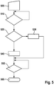
- a branch is preferably made automatically from program point 410 to program point 420 if a predetermined first period of time has passed since the operation of the electric motor, in particular since the start of impact operation of the power tool, even if the conditions of program point 410 are not met.
- the duration of the drive time during impact operation for example, a map, a characteristic curve or a corresponding calculation method is used with which, depending on the standard deviation of the current, and / or depending on the mean standard deviation of the current and / or depending on the standard deviation of the Speed, and / or the drive time is determined as a function of the mean standard deviation of the speed.
- the state of charge of the battery for example, is also taken into account.
- the drive time determined is stored in memory 51.
- the program then branches to program point 450.
- a high speed at program point 440 is required in order to provide a sufficiently high torque for a tool with a large diameter.
- a medium speed at program point 430 ensures that a tool with a smaller diameter does not break off.
- the limit values W, I for the speed and the current are selected accordingly. If the check at program point 510 shows that the speed n is greater than the limit value W and that the current i of the electric motor is greater than the limit value I, then a predefined operating state, in particular impact operation, is recognized and a branch is made to program point 520.
- control circuit 46 outputs a warning signal when the voltage of the battery 19 falls below a predetermined minimum value which is stored in the memory 51. This ensures that the user of the power tool has the option of recharging the battery or adapting the drive time, the rotational speed and / or the torque accordingly in order to achieve a desired drilling result or screwing-in result.
- an electronic clutch is activated before the electric motor is switched off, the torque on the tool is reduced and the electric motor is then switched off.
- the state of charge of the battery is preferably determined each time a program sequence is started, for example by detecting the voltage of the battery.
- Figure 9 shows a further embodiment of the Figure 7 , after program point 720 instead of a simple braking process according to program point 740 of Figure 8 the rotational speed of the electric motor is reduced according to a predetermined speed profile by the control circuit 46 by a corresponding activation of the drive coils 23c and then the electric motor is stopped at a following program point 730.
- the speed profile of program step 750 can consist, for example, in a linear decrease in the speed or in a gradual decrease in the speed of the electric motor 20. Depending on the embodiment selected, other speed profiles can also be used.
- a soft braking process can be used to stop the electric motor at the end of the process.
- the speed of the motor can be reduced or braked to a predetermined low speed.
- the electric motor can be braked until the speed of the electric motor is lower than the mechanical resistance of the electric tool.
- the speed of the electric motor is then gradually reduced to zero. In this way, the motor is braked more quickly to zero speed.
- the electric motor can be braked mechanically or by a corresponding electrical control of the electric motor.
- the trigger 18t is pressed completely to the stop, so that a maximum speed of the electric motor of the power tool is desired by the operator.
- a speed of the actuation of the trigger 18t can also be detected. The speed at which the trigger 18t is actuated can be taken into account in the following automatic methods in addition to or instead of the actuation travel of the trigger 18t.
- the first time period t1 can be between 0.03 and 0.1 seconds, for example. If this is the case, a branch is then made to a following program point 840. If this is not the case, program point 820 continues to be carried out.
- the speed of the electric motor continues to be set as a function of the type of actuation of trigger 18t, as at program point 820.
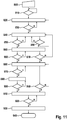
- a following program point 850 it is checked whether the current of the electric motor rises above a predetermined third limit value I3. If this is the case, the counter is increased by the value 1 to the value 1 and a branch is made to a following program point 860. This is the case in the present first operating situation.
- a torque sensor on the power tool can also be used to measure the seating torque of the screw in the initial phase.
- the limit values can be determined or determined by the control circuit as a function of the torque or the seating torque of the screw that occurs when the screw is started to be unscrewed. For example, correspondingly different values for the first, the second, the third and / or the fourth limit value can be stored for predetermined torque ranges. Otherwise, the procedure is carried out according to the first operating situation.
- the electric motor is operated at maximum speed. Subsequently, at program point 950, a check is made as to whether the current of the electric motor exhibits a greater decrease over time than a predefined value.
- the specified value for the temporal drop in the current is stored in the memory. If the query at program point 950 shows that the measured drop over time is less than the specified value, then the program branches back to program point 880. If the query at program point 950 shows that the measured drop over time is greater than the predefined value, the program branches to program point 910. If the drop in current over time is greater than the specified value, this indicates that the screw has been loosened. Program points 910 to 940 are then processed accordingly.
- the program is from Figure 11 Run through as follows: The program starts at program point 800, at which the power tool is put into operation.
- the switch 70 is in the position in which the automatic method for preventing complete loosening of the screw from the workpiece is activated.
- a program point 810 it is then checked whether the power tool is in the operating mode of unscrewing a screw, that is to say, for example, turning it to the left. If this is the case, a counter is set to the value zero at a subsequent program point 820.
- an operator can set a low speed and / or a slow increase in speed for loosening the screw.
- the detection of the rotational speed can be detected on the basis of the type of actuation of the trigger 18t. If the trigger 18t is pressed completely to the stop, a maximum speed of the electric motor is desired by the operator.
- a speed of the actuation of the trigger 18t can also be recorded and, in addition or instead of the actuation path of the trigger 18t, also the speed of the actuation of the trigger 18t in the following automatic method must be taken into account.
- the speed of actuation of the trigger and / or the actuation path of the trigger can be detected with appropriate sensors and passed to the control circuit 46.
- program point 820 is retained until the current is above the first limit value I1.
- the program then branches to program point 840. If the operator reduces the speed of the power tool during program point 840, then the current falls below the second limit value I2, so that the query at program point 890 results in a branch back to program point 820.
- the fourth limit value I4 has a greater value than in the fourth operating situation.
- the query at program point 870 thus shows that the current is less than the fourth limit value. This branches back to program point 840.
- the current is greater than the third limit value I3, so that, according to program point 850, a branch is made to program point 860 again.
- the counter is increased by the value 1 to the value 2.
- the query at program point 870 takes place.
- the query again shows that the current is less than the fourth limit value I4, so that the program then branches back to program point 840.
- the following query at program point 850 again shows that the current is greater than the third limit value is I3, so that the counter is increased by the value 1 to the value 3 and the program branches to program point 860.
- the specified comparison value is stored in the memory as a negative temporal gradient of the current, for example. If the query at program point 950 shows that the measured drop in the current over time is less than the comparison value, a branch is made to program point 910. Program points 910, 920, 930 and 940 are then carried out as described.
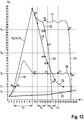
- Figure 12 shows in a diagram the current I over time t for various methods for automatically unscrewing a screw without completely loosening the screw from the workpiece, according to the program sequence of FIG Figure 11 can be carried out.
- a first characteristic curve 73 characterizes the first operating situation.
- a second characteristic curve 74 characterizes the second operating situation.
- a third characteristic curve 75 represents a third operating situation.
- the first three characteristic curves 73, 74, 75 are designed identically for the selected embodiments in an initial phase.
- a fourth characteristic curve 76 represents a fourth operating situation.
- a fifth characteristic curve 77 represents a fifth operating situation.
Landscapes
- Engineering & Computer Science (AREA)
- Mechanical Engineering (AREA)
- Power Engineering (AREA)
- Details Of Spanners, Wrenches, And Screw Drivers And Accessories (AREA)
- Control Of Electric Motors In General (AREA)
- Percussive Tools And Related Accessories (AREA)
Claims (6)
- Procédé de commande d'un moteur électrique d'un outil électrique pourvu d'un logement destiné à un outil de dévissage d'une vis d'une contre-pièce, le moteur électrique étant arrêté lors du dévissage d'une vis si le couple fourni par le moteur électrique tombe au-dessous d'une valeur limite spécifiée, ou si la vis a été dévissée d'une position de fixation d'un nombre de tours spécifié, le couple étant déterminé sur la base d'une variation dans le temps du courant qui est absorbé par le moteur électrique lors du dévissage de la vis, et la vitesse de rotation du moteur électrique étant au moins réduite lorsque le courant chute plus rapidement qu'un gradient de comparaison temporel, caractérisé en ce que le gradient de comparaison peut prendre différentes valeurs en fonction d'une vitesse de rotation du moteur électrique spécifiée par un opérateur et/ou en fonction d'une vitesse d'actionnement d'un interrupteur pour spécifier la vitesse de rotation.
- Procédé selon la revendication 1, la valeur limite et/ou le nombre de tours étant déterminés par un opérateur.
- Procédé selon la revendication 1 ou 2, le couple délivré étant détecté sur la base d'un courant qui est absorbé par le moteur électrique, et la vitesse de rotation du moteur électrique étant au moins réduite lorsque le courant tombe au-dessous d'une valeur limite.
- Procédé selon l'une des revendications précédentes, la valeur limite et/ou le gradient de comparaison étant déterminés en fonction d'un couple de fixation de la vis.
- Procédé selon la revendication 4, le couple de fixation de la vis étant estimé à partir d'un courant absorbé par le moteur électrique, notamment dans une phase initiale lors du dévissage de la vis.
- Procédé selon l'une des revendications précédentes, une tension de batterie étant vérifiée avec laquelle le moteur électrique est entraîné, une indication étant délivrée si la tension de la batterie est inférieure à une valeur minimale spécifiée.
Priority Applications (1)
| Application Number | Priority Date | Filing Date | Title |
|---|---|---|---|
| EP21181782.0A EP3960375A3 (fr) | 2014-06-20 | 2015-06-18 | Procédé de commande d'un moteur électrique d'un outil électrique |
Applications Claiming Priority (3)
| Application Number | Priority Date | Filing Date | Title |
|---|---|---|---|
| DE102014211894 | 2014-06-20 | ||
| DE102015211119.9A DE102015211119A1 (de) | 2014-06-20 | 2015-06-17 | Verfahren zum Steuern eines Elektromotors eines Elektrowerkzeuges |
| PCT/EP2015/063706 WO2015193431A2 (fr) | 2014-06-20 | 2015-06-18 | Procédé pour commander un moteur électrique d'un outil électrique |
Related Child Applications (2)
| Application Number | Title | Priority Date | Filing Date |
|---|---|---|---|
| EP21181782.0A Division EP3960375A3 (fr) | 2014-06-20 | 2015-06-18 | Procédé de commande d'un moteur électrique d'un outil électrique |
| EP21181782.0A Division-Into EP3960375A3 (fr) | 2014-06-20 | 2015-06-18 | Procédé de commande d'un moteur électrique d'un outil électrique |
Publications (2)
| Publication Number | Publication Date |
|---|---|
| EP3157712A2 EP3157712A2 (fr) | 2017-04-26 |
| EP3157712B1 true EP3157712B1 (fr) | 2021-08-11 |
Family
ID=54768167
Family Applications (2)
| Application Number | Title | Priority Date | Filing Date |
|---|---|---|---|
| EP15731024.4A Active EP3157712B1 (fr) | 2014-06-20 | 2015-06-18 | Procédé pour commander un moteur électrique d'un outil électrique |
| EP21181782.0A Pending EP3960375A3 (fr) | 2014-06-20 | 2015-06-18 | Procédé de commande d'un moteur électrique d'un outil électrique |
Family Applications After (1)
| Application Number | Title | Priority Date | Filing Date |
|---|---|---|---|
| EP21181782.0A Pending EP3960375A3 (fr) | 2014-06-20 | 2015-06-18 | Procédé de commande d'un moteur électrique d'un outil électrique |
Country Status (5)
| Country | Link |
|---|---|
| US (2) | US11491617B2 (fr) |
| EP (2) | EP3157712B1 (fr) |
| JP (1) | JP6406792B2 (fr) |
| DE (1) | DE102015211119A1 (fr) |
| WO (1) | WO2015193431A2 (fr) |
Families Citing this family (31)
| Publication number | Priority date | Publication date | Assignee | Title |
|---|---|---|---|---|
| DE102015211119A1 (de) * | 2014-06-20 | 2015-12-24 | Robert Bosch Gmbh | Verfahren zum Steuern eines Elektromotors eines Elektrowerkzeuges |
| US11133662B2 (en) * | 2015-09-01 | 2021-09-28 | Black & Decker Inc. | Battery pack adaptor with overstress detection circuit |
| DE102015226374A1 (de) * | 2015-12-21 | 2017-06-22 | Robert Bosch Gmbh | Verfahren zum Betreiben eines Elektrowerkzeuges |
| JP6755154B2 (ja) * | 2016-09-28 | 2020-09-16 | 株式会社マキタ | 電動工具 |
| DE102017101727B4 (de) | 2017-01-30 | 2018-10-31 | Bayerische Motoren Werke Aktiengesellschaft | Verfahren zur Ermittlung einer Zeitdauer bei einem Reifenwechsel eines Fahrzeugs, System, Computerprogramm und Computerprogrammprodukt |
| DE102017103003A1 (de) | 2017-02-15 | 2018-08-16 | Metabowerke Gmbh | Verfahren zum Abbremsen einer Werkzeugspindel |
| WO2019089314A2 (fr) * | 2017-10-30 | 2019-05-09 | Ethicon Llc | Algorithme réactif pour système chirurgical |
| US11897110B2 (en) * | 2017-11-07 | 2024-02-13 | Milwaukee Electric Tool Corporation | Non-contact speed selector switch in rotary power tool |
| EP3501740A1 (fr) * | 2017-12-20 | 2019-06-26 | HILTI Aktiengesellschaft | Procédé de pose pour raccord à vis au moyen de clé à percussion |
| US11318589B2 (en) * | 2018-02-19 | 2022-05-03 | Milwaukee Electric Tool Corporation | Impact tool |
| EP3894136A4 (fr) * | 2018-12-10 | 2023-01-11 | Milwaukee Electric Tool Corporation | Outil d'impact à couple élevé |
| WO2020132587A1 (fr) * | 2018-12-21 | 2020-06-25 | Milwaukee Electric Tool Corporation | Outil à impact à couple élevé |
| DE102019200527A1 (de) * | 2019-01-17 | 2020-07-23 | Robert Bosch Gmbh | Handwerkzeugmaschine |
| KR102291032B1 (ko) * | 2019-02-21 | 2021-08-20 | 계양전기 주식회사 | 전동 공구 및 이의 제어 방법 |
| DE102019204071A1 (de) * | 2019-03-25 | 2020-10-01 | Robert Bosch Gmbh | Verfahren zur Erkennung eines ersten Betriebszustandes einer Handwerkzeugmaschine |
| DE102019125114A1 (de) * | 2019-09-18 | 2021-03-18 | Hoffmann Engineering Services GmbH | Kalibrierbares Werkzeug, Kalibriersystem und Verfahren zum Betreiben eines kalibrierbaren Werkzeugs |
| JP7386027B2 (ja) * | 2019-09-27 | 2023-11-24 | 株式会社マキタ | 回転打撃工具 |
| JP7320419B2 (ja) | 2019-09-27 | 2023-08-03 | 株式会社マキタ | 回転打撃工具 |
| JP7296587B2 (ja) * | 2019-11-15 | 2023-06-23 | パナソニックIpマネジメント株式会社 | 電動工具、制御方法、及びプログラム |
| JP7178591B2 (ja) * | 2019-11-15 | 2022-11-28 | パナソニックIpマネジメント株式会社 | インパクト工具、インパクト工具の制御方法及びプログラム |
| JP7296586B2 (ja) * | 2019-11-15 | 2023-06-23 | パナソニックIpマネジメント株式会社 | 電動工具、制御方法、及びプログラム |
| WO2021095470A1 (fr) * | 2019-11-15 | 2021-05-20 | パナソニックIpマネジメント株式会社 | Outil électrique, procédé de commande et programme |
| DE102020208993A1 (de) * | 2019-12-19 | 2021-06-24 | Robert Bosch Gesellschaft mit beschränkter Haftung | Verfahren zum Betreiben einer Handwerkzeugmaschine |
| EP3864956B1 (fr) | 2020-02-14 | 2022-12-14 | Andreas Stihl AG & Co. KG | Appareil de jardinage, de foresterie et/ou de construction guidé à la main et procédé de fonctionnement d'un appareil de jardinage, de foresterie et/ou de construction guidé à la main |
| USD948978S1 (en) | 2020-03-17 | 2022-04-19 | Milwaukee Electric Tool Corporation | Rotary impact wrench |
| EP4175791A4 (fr) * | 2020-07-06 | 2024-08-07 | Milwaukee Electric Tool Corp | Détection automatique de charge de rampe pour outils électriques |
| US20240097431A1 (en) * | 2022-09-20 | 2024-03-21 | Black & Decker Inc. | Constant-clutch operation at power tool start-up |
| EP4263138A1 (fr) | 2020-12-18 | 2023-10-25 | Black & Decker Inc. | Outils à percussion et modes de commande |
| US11602826B2 (en) * | 2021-07-19 | 2023-03-14 | Te Huang Wang | Electric apparatus and control method thereof |
| TWI793967B (zh) * | 2022-01-10 | 2023-02-21 | 碩豐工業股份有限公司 | 離合型動力傳輸裝置及其轉速控制模組 |
| DE102022003797A1 (de) | 2022-10-14 | 2024-04-25 | Mercedes-Benz Group AG | Verfahren zur Überwachung einer Herstellung einer Schraubverbindung und Vorrichtung zur Durchführung des Verfahrens |
Family Cites Families (36)
| Publication number | Priority date | Publication date | Assignee | Title |
|---|---|---|---|---|
| US3939920A (en) * | 1974-09-19 | 1976-02-24 | Standard Pressed Steel Co. | Tightening method and system |
| JP2807036B2 (ja) * | 1990-04-16 | 1998-09-30 | 株式会社ジャパンエナジー | 自動ねじ締め方法及び装置 |
| US5587931A (en) * | 1995-10-20 | 1996-12-24 | Tri-Way Machine Ltd. | Tool condition monitoring system |
| JPH1080828A (ja) * | 1996-09-06 | 1998-03-31 | Toyota Motor Corp | ナットランナの制御方法 |
| US6311786B1 (en) * | 1998-12-03 | 2001-11-06 | Chicago Pneumatic Tool Company | Process of determining torque output and controlling power impact tools using impulse |
| US6581696B2 (en) * | 1998-12-03 | 2003-06-24 | Chicago Pneumatic Tool Company | Processes of determining torque output and controlling power impact tools using a torque transducer |
| ATE316845T1 (de) * | 1999-03-16 | 2006-02-15 | Kuken Co Ltd | Verfahren zum ermitteln des schraubendrehwinkels von handdrehimpulsschraubern, verfahren zum feststellen von handvibratoren,verfahren zur auswertung vom anziehen und überwachungsverfahren eines angetriebenen handwerkzeugs zum lösen von schrauben |
| JP2001129768A (ja) | 1999-10-29 | 2001-05-15 | Matsushita Electric Works Ltd | インパクト回転工具 |
| EP1136188B1 (fr) * | 2000-03-16 | 2007-05-16 | Makita Corporation | Outil à impact motorisé avec moyens de repérage du bruit d'impact |
| JP3660554B2 (ja) * | 2000-03-24 | 2005-06-15 | 株式会社マキタ | 締付工具 |
| JP2005066785A (ja) * | 2003-08-26 | 2005-03-17 | Matsushita Electric Works Ltd | 電動工具 |
| JP2005118910A (ja) * | 2003-10-14 | 2005-05-12 | Matsushita Electric Works Ltd | インパクト回転工具 |
| JP4368292B2 (ja) * | 2004-12-01 | 2009-11-18 | 前田金属工業株式会社 | 電動締付機 |
| JP4211744B2 (ja) * | 2005-02-23 | 2009-01-21 | パナソニック電工株式会社 | インパクト締付け工具 |
| DE102006015664A1 (de) * | 2005-04-04 | 2007-01-25 | Hitachi Koki Co., Ltd. | Batteriepack und kabelloses elektrisches Werkzeug, das dieses aufweist |
| US20070244471A1 (en) * | 2005-10-21 | 2007-10-18 | Don Malackowski | System and method for managing the operation of a battery powered surgical tool and the battery used to power the tool |
| JP4293222B2 (ja) | 2006-10-12 | 2009-07-08 | パナソニック電工株式会社 | インパクト工具 |
| DE102007000281A1 (de) * | 2007-05-21 | 2008-11-27 | Hilti Aktiengesellschaft | Verfahren zur Steuerung eines Schraubgerätes |
| US8074731B2 (en) * | 2007-09-21 | 2011-12-13 | Hitachi Koki Co., Ltd. | Impact tool |
| JP4412377B2 (ja) * | 2007-09-28 | 2010-02-10 | パナソニック電工株式会社 | インパクト回転工具 |
| JP2009262273A (ja) | 2008-04-24 | 2009-11-12 | Panasonic Electric Works Co Ltd | インパクト回転工具 |
| JP5405157B2 (ja) * | 2009-03-10 | 2014-02-05 | 株式会社マキタ | 回転打撃工具 |
| JP5234287B2 (ja) * | 2009-04-07 | 2013-07-10 | マックス株式会社 | 電動工具およびそのモータ制御方法 |
| US9314908B2 (en) * | 2009-07-29 | 2016-04-19 | Hitachi Koki Co., Ltd. | Impact tool |
| JP5483089B2 (ja) * | 2010-03-11 | 2014-05-07 | 日立工機株式会社 | インパクト工具 |
| JP5464014B2 (ja) * | 2010-03-31 | 2014-04-09 | 日立工機株式会社 | 電動工具 |
| JP5464434B2 (ja) * | 2010-03-31 | 2014-04-09 | 日立工機株式会社 | 電動工具 |
| JP5769385B2 (ja) * | 2010-05-31 | 2015-08-26 | 日立工機株式会社 | 電動工具 |
| JP2013022681A (ja) * | 2011-07-21 | 2013-02-04 | Hitachi Koki Co Ltd | 電動工具 |
| JP5784473B2 (ja) * | 2011-11-30 | 2015-09-24 | 株式会社マキタ | 回転打撃工具 |
| JP2013188812A (ja) * | 2012-03-13 | 2013-09-26 | Hitachi Koki Co Ltd | インパクト工具 |
| JP5974616B2 (ja) * | 2012-04-30 | 2016-08-23 | 日立工機株式会社 | 電動工具 |
| JP6304533B2 (ja) * | 2014-03-04 | 2018-04-04 | パナソニックIpマネジメント株式会社 | インパクト回転工具 |
| DE102015211119A1 (de) * | 2014-06-20 | 2015-12-24 | Robert Bosch Gmbh | Verfahren zum Steuern eines Elektromotors eines Elektrowerkzeuges |
| DE102014211891A1 (de) * | 2014-06-20 | 2015-12-24 | Robert Bosch Gmbh | Verfahren zum Betreiben eines Elektrowerkzeuges |
| US10144148B2 (en) * | 2014-08-12 | 2018-12-04 | Robert Bosch Tool Corporation | System and method for kickback detection in a circular saw |
-
2015
- 2015-06-17 DE DE102015211119.9A patent/DE102015211119A1/de not_active Withdrawn
- 2015-06-18 WO PCT/EP2015/063706 patent/WO2015193431A2/fr active Application Filing
- 2015-06-18 EP EP15731024.4A patent/EP3157712B1/fr active Active
- 2015-06-18 EP EP21181782.0A patent/EP3960375A3/fr active Pending
- 2015-06-18 US US15/312,715 patent/US11491617B2/en active Active
- 2015-06-18 JP JP2017517419A patent/JP6406792B2/ja active Active
-
2022
- 2022-05-27 US US17/826,871 patent/US11975427B2/en active Active
Non-Patent Citations (1)
| Title |
|---|
| None * |
Also Published As
| Publication number | Publication date |
|---|---|
| US20220281086A1 (en) | 2022-09-08 |
| JP2017517407A (ja) | 2017-06-29 |
| EP3960375A2 (fr) | 2022-03-02 |
| WO2015193431A2 (fr) | 2015-12-23 |
| US20170190032A1 (en) | 2017-07-06 |
| EP3157712A2 (fr) | 2017-04-26 |
| US11491617B2 (en) | 2022-11-08 |
| US11975427B2 (en) | 2024-05-07 |
| JP6406792B2 (ja) | 2018-10-17 |
| EP3960375A3 (fr) | 2022-11-16 |
| WO2015193431A3 (fr) | 2016-03-17 |
| DE102015211119A1 (de) | 2015-12-24 |
Similar Documents
| Publication | Publication Date | Title |
|---|---|---|
| EP3157712B1 (fr) | Procédé pour commander un moteur électrique d'un outil électrique | |
| EP3157711B1 (fr) | Procédé permettant de faire fonctionner un outil électrique | |
| DE102015001982B4 (de) | Drehschlagwerkzeug | |
| DE102015013532B4 (de) | Elektrisches Kraftwerkzeug | |
| EP2397258B1 (fr) | Visseuse | |
| DE102013201708B4 (de) | Elektrische Werkzeugmaschine und Verfahren zum Steuern der elektrischen Werkzeugmaschine | |
| EP2675592B1 (fr) | Machine-outil à main, en particulier visseuse à accumulateur | |
| DE102016115538A1 (de) | Drehschlagwerkzeug und Verfahren zum Steuern desselben | |
| DE212014000108U1 (de) | Elektrowerkzeug | |
| DE102007000281A1 (de) | Verfahren zur Steuerung eines Schraubgerätes | |
| DE102018119023A1 (de) | Elektrische arbeitsmaschine und verfahren zum steuern eines drehzustands eines motors einer elektrischen arbeitsmaschine | |
| DE202017003590U1 (de) | Elektrisch angetriebenes Werkzeug | |
| DE102007059422A1 (de) | Verfahren zum Setzen von Nietelementen durch ein von einem Elektromotor angetriebenes portables Nietgerät sowie ein Nietgerät | |
| DE102009054762A1 (de) | Steuerungsverfahren für eine handgeführte Werkzeugmaschine und Werkzeugmaschine | |
| DE102006016448A1 (de) | Elektrowerkzeugmaschine und Verfahren zum Betreiben derselben | |
| DE102018119021A1 (de) | Elektrische arbeitsmaschine und verfahren zum steuern eines drehzustands eines motors einer elektrischen arbeitsmaschine | |
| DE102011102275A1 (de) | Schrauber und Verfahren zum Steuern eines Schraubers | |
| DE19620782A1 (de) | Verfahren zur Herstellung einer Schraubverbindung und Vorrichtung hierfür | |
| DE102016212520B4 (de) | Verfahren zum Betreiben eines Elektrowerkzeuges | |
| EP1785231A2 (fr) | Outil de vissage à régulation de vitesse de rotation et méthode de régulation de vitesse pour un outil de vissage | |
| DE102018208302A1 (de) | Verfahren zum Anziehen einer Schraubverbindung | |
| WO2012079936A2 (fr) | Procédé et dispositif permettant de faire fonctionner un outil à main à moteur électrique | |
| WO2016116250A1 (fr) | Procédé pour faire fonctionner un moteur électrique d'un outil électrique | |
| EP3393710B1 (fr) | Procédé permettant de faire fonctionner un outil électrique | |
| DE112021003035T5 (de) | Festziehwerkzeug |
Legal Events
| Date | Code | Title | Description |
|---|---|---|---|
| STAA | Information on the status of an ep patent application or granted ep patent |
Free format text: STATUS: THE INTERNATIONAL PUBLICATION HAS BEEN MADE |
|
| PUAI | Public reference made under article 153(3) epc to a published international application that has entered the european phase |
Free format text: ORIGINAL CODE: 0009012 |
|
| STAA | Information on the status of an ep patent application or granted ep patent |
Free format text: STATUS: REQUEST FOR EXAMINATION WAS MADE |
|
| 17P | Request for examination filed |
Effective date: 20170120 |
|
| AK | Designated contracting states |
Kind code of ref document: A2 Designated state(s): AL AT BE BG CH CY CZ DE DK EE ES FI FR GB GR HR HU IE IS IT LI LT LU LV MC MK MT NL NO PL PT RO RS SE SI SK SM TR |
|
| AX | Request for extension of the european patent |
Extension state: BA ME |
|
| DAV | Request for validation of the european patent (deleted) | ||
| DAX | Request for extension of the european patent (deleted) | ||
| STAA | Information on the status of an ep patent application or granted ep patent |
Free format text: STATUS: EXAMINATION IS IN PROGRESS |
|
| RAP1 | Party data changed (applicant data changed or rights of an application transferred) |
Owner name: ROBERT BOSCH GMBH |
|
| 17Q | First examination report despatched |
Effective date: 20200420 |
|
| STAA | Information on the status of an ep patent application or granted ep patent |
Free format text: STATUS: EXAMINATION IS IN PROGRESS |
|
| REG | Reference to a national code |
Ref country code: DE Ref legal event code: R079 Ref document number: 502015015051 Country of ref document: DE Free format text: PREVIOUS MAIN CLASS: B25B0023147000 Ipc: B25F0005000000 |
|
| GRAP | Despatch of communication of intention to grant a patent |
Free format text: ORIGINAL CODE: EPIDOSNIGR1 |
|
| STAA | Information on the status of an ep patent application or granted ep patent |
Free format text: STATUS: GRANT OF PATENT IS INTENDED |
|
| RIC1 | Information provided on ipc code assigned before grant |
Ipc: B25F 5/00 20060101AFI20210225BHEP |
|
| INTG | Intention to grant announced |
Effective date: 20210317 |
|
| GRAS | Grant fee paid |
Free format text: ORIGINAL CODE: EPIDOSNIGR3 |
|
| GRAA | (expected) grant |
Free format text: ORIGINAL CODE: 0009210 |
|
| STAA | Information on the status of an ep patent application or granted ep patent |
Free format text: STATUS: THE PATENT HAS BEEN GRANTED |
|
| AK | Designated contracting states |
Kind code of ref document: B1 Designated state(s): AL AT BE BG CH CY CZ DE DK EE ES FI FR GB GR HR HU IE IS IT LI LT LU LV MC MK MT NL NO PL PT RO RS SE SI SK SM TR |
|
| REG | Reference to a national code |
Ref country code: CH Ref legal event code: EP |
|
| REG | Reference to a national code |
Ref country code: DE Ref legal event code: R096 Ref document number: 502015015051 Country of ref document: DE |
|
| REG | Reference to a national code |
Ref country code: IE Ref legal event code: FG4D Free format text: LANGUAGE OF EP DOCUMENT: GERMAN Ref country code: AT Ref legal event code: REF Ref document number: 1418898 Country of ref document: AT Kind code of ref document: T Effective date: 20210915 |
|
| REG | Reference to a national code |
Ref country code: LT Ref legal event code: MG9D |
|
| REG | Reference to a national code |
Ref country code: NL Ref legal event code: MP Effective date: 20210811 |
|
| PG25 | Lapsed in a contracting state [announced via postgrant information from national office to epo] |
Ref country code: LT Free format text: LAPSE BECAUSE OF FAILURE TO SUBMIT A TRANSLATION OF THE DESCRIPTION OR TO PAY THE FEE WITHIN THE PRESCRIBED TIME-LIMIT Effective date: 20210811 Ref country code: BG Free format text: LAPSE BECAUSE OF FAILURE TO SUBMIT A TRANSLATION OF THE DESCRIPTION OR TO PAY THE FEE WITHIN THE PRESCRIBED TIME-LIMIT Effective date: 20211111 Ref country code: ES Free format text: LAPSE BECAUSE OF FAILURE TO SUBMIT A TRANSLATION OF THE DESCRIPTION OR TO PAY THE FEE WITHIN THE PRESCRIBED TIME-LIMIT Effective date: 20210811 Ref country code: FI Free format text: LAPSE BECAUSE OF FAILURE TO SUBMIT A TRANSLATION OF THE DESCRIPTION OR TO PAY THE FEE WITHIN THE PRESCRIBED TIME-LIMIT Effective date: 20210811 Ref country code: PT Free format text: LAPSE BECAUSE OF FAILURE TO SUBMIT A TRANSLATION OF THE DESCRIPTION OR TO PAY THE FEE WITHIN THE PRESCRIBED TIME-LIMIT Effective date: 20211213 Ref country code: NO Free format text: LAPSE BECAUSE OF FAILURE TO SUBMIT A TRANSLATION OF THE DESCRIPTION OR TO PAY THE FEE WITHIN THE PRESCRIBED TIME-LIMIT Effective date: 20211111 Ref country code: SE Free format text: LAPSE BECAUSE OF FAILURE TO SUBMIT A TRANSLATION OF THE DESCRIPTION OR TO PAY THE FEE WITHIN THE PRESCRIBED TIME-LIMIT Effective date: 20210811 Ref country code: RS Free format text: LAPSE BECAUSE OF FAILURE TO SUBMIT A TRANSLATION OF THE DESCRIPTION OR TO PAY THE FEE WITHIN THE PRESCRIBED TIME-LIMIT Effective date: 20210811 Ref country code: HR Free format text: LAPSE BECAUSE OF FAILURE TO SUBMIT A TRANSLATION OF THE DESCRIPTION OR TO PAY THE FEE WITHIN THE PRESCRIBED TIME-LIMIT Effective date: 20210811 |
|
| PG25 | Lapsed in a contracting state [announced via postgrant information from national office to epo] |
Ref country code: PL Free format text: LAPSE BECAUSE OF FAILURE TO SUBMIT A TRANSLATION OF THE DESCRIPTION OR TO PAY THE FEE WITHIN THE PRESCRIBED TIME-LIMIT Effective date: 20210811 Ref country code: LV Free format text: LAPSE BECAUSE OF FAILURE TO SUBMIT A TRANSLATION OF THE DESCRIPTION OR TO PAY THE FEE WITHIN THE PRESCRIBED TIME-LIMIT Effective date: 20210811 Ref country code: GR Free format text: LAPSE BECAUSE OF FAILURE TO SUBMIT A TRANSLATION OF THE DESCRIPTION OR TO PAY THE FEE WITHIN THE PRESCRIBED TIME-LIMIT Effective date: 20211112 |
|
| PG25 | Lapsed in a contracting state [announced via postgrant information from national office to epo] |
Ref country code: NL Free format text: LAPSE BECAUSE OF FAILURE TO SUBMIT A TRANSLATION OF THE DESCRIPTION OR TO PAY THE FEE WITHIN THE PRESCRIBED TIME-LIMIT Effective date: 20210811 |
|
| PG25 | Lapsed in a contracting state [announced via postgrant information from national office to epo] |
Ref country code: DK Free format text: LAPSE BECAUSE OF FAILURE TO SUBMIT A TRANSLATION OF THE DESCRIPTION OR TO PAY THE FEE WITHIN THE PRESCRIBED TIME-LIMIT Effective date: 20210811 |
|
| REG | Reference to a national code |
Ref country code: DE Ref legal event code: R097 Ref document number: 502015015051 Country of ref document: DE |
|
| PG25 | Lapsed in a contracting state [announced via postgrant information from national office to epo] |
Ref country code: SM Free format text: LAPSE BECAUSE OF FAILURE TO SUBMIT A TRANSLATION OF THE DESCRIPTION OR TO PAY THE FEE WITHIN THE PRESCRIBED TIME-LIMIT Effective date: 20210811 Ref country code: SK Free format text: LAPSE BECAUSE OF FAILURE TO SUBMIT A TRANSLATION OF THE DESCRIPTION OR TO PAY THE FEE WITHIN THE PRESCRIBED TIME-LIMIT Effective date: 20210811 Ref country code: RO Free format text: LAPSE BECAUSE OF FAILURE TO SUBMIT A TRANSLATION OF THE DESCRIPTION OR TO PAY THE FEE WITHIN THE PRESCRIBED TIME-LIMIT Effective date: 20210811 Ref country code: EE Free format text: LAPSE BECAUSE OF FAILURE TO SUBMIT A TRANSLATION OF THE DESCRIPTION OR TO PAY THE FEE WITHIN THE PRESCRIBED TIME-LIMIT Effective date: 20210811 Ref country code: CZ Free format text: LAPSE BECAUSE OF FAILURE TO SUBMIT A TRANSLATION OF THE DESCRIPTION OR TO PAY THE FEE WITHIN THE PRESCRIBED TIME-LIMIT Effective date: 20210811 Ref country code: AL Free format text: LAPSE BECAUSE OF FAILURE TO SUBMIT A TRANSLATION OF THE DESCRIPTION OR TO PAY THE FEE WITHIN THE PRESCRIBED TIME-LIMIT Effective date: 20210811 |
|
| PLBE | No opposition filed within time limit |
Free format text: ORIGINAL CODE: 0009261 |
|
| STAA | Information on the status of an ep patent application or granted ep patent |
Free format text: STATUS: NO OPPOSITION FILED WITHIN TIME LIMIT |
|
| 26N | No opposition filed |
Effective date: 20220512 |
|
| PG25 | Lapsed in a contracting state [announced via postgrant information from national office to epo] |
Ref country code: IT Free format text: LAPSE BECAUSE OF FAILURE TO SUBMIT A TRANSLATION OF THE DESCRIPTION OR TO PAY THE FEE WITHIN THE PRESCRIBED TIME-LIMIT Effective date: 20210811 |
|
| PG25 | Lapsed in a contracting state [announced via postgrant information from national office to epo] |
Ref country code: SI Free format text: LAPSE BECAUSE OF FAILURE TO SUBMIT A TRANSLATION OF THE DESCRIPTION OR TO PAY THE FEE WITHIN THE PRESCRIBED TIME-LIMIT Effective date: 20210811 |
|
| PG25 | Lapsed in a contracting state [announced via postgrant information from national office to epo] |
Ref country code: MC Free format text: LAPSE BECAUSE OF FAILURE TO SUBMIT A TRANSLATION OF THE DESCRIPTION OR TO PAY THE FEE WITHIN THE PRESCRIBED TIME-LIMIT Effective date: 20210811 |
|
| REG | Reference to a national code |
Ref country code: CH Ref legal event code: PL |
|
| REG | Reference to a national code |
Ref country code: BE Ref legal event code: MM Effective date: 20220630 |
|
| PG25 | Lapsed in a contracting state [announced via postgrant information from national office to epo] |
Ref country code: LU Free format text: LAPSE BECAUSE OF NON-PAYMENT OF DUE FEES Effective date: 20220618 Ref country code: LI Free format text: LAPSE BECAUSE OF NON-PAYMENT OF DUE FEES Effective date: 20220630 Ref country code: IE Free format text: LAPSE BECAUSE OF NON-PAYMENT OF DUE FEES Effective date: 20220618 Ref country code: CH Free format text: LAPSE BECAUSE OF NON-PAYMENT OF DUE FEES Effective date: 20220630 |
|
| PG25 | Lapsed in a contracting state [announced via postgrant information from national office to epo] |
Ref country code: BE Free format text: LAPSE BECAUSE OF NON-PAYMENT OF DUE FEES Effective date: 20220630 |
|
| REG | Reference to a national code |
Ref country code: AT Ref legal event code: MM01 Ref document number: 1418898 Country of ref document: AT Kind code of ref document: T Effective date: 20220618 |
|
| PG25 | Lapsed in a contracting state [announced via postgrant information from national office to epo] |
Ref country code: AT Free format text: LAPSE BECAUSE OF NON-PAYMENT OF DUE FEES Effective date: 20220618 |
|
| PGFP | Annual fee paid to national office [announced via postgrant information from national office to epo] |
Ref country code: DE Payment date: 20230817 Year of fee payment: 9 |
|
| PG25 | Lapsed in a contracting state [announced via postgrant information from national office to epo] |
Ref country code: HU Free format text: LAPSE BECAUSE OF FAILURE TO SUBMIT A TRANSLATION OF THE DESCRIPTION OR TO PAY THE FEE WITHIN THE PRESCRIBED TIME-LIMIT; INVALID AB INITIO Effective date: 20150618 |
|
| PG25 | Lapsed in a contracting state [announced via postgrant information from national office to epo] |
Ref country code: MK Free format text: LAPSE BECAUSE OF FAILURE TO SUBMIT A TRANSLATION OF THE DESCRIPTION OR TO PAY THE FEE WITHIN THE PRESCRIBED TIME-LIMIT Effective date: 20210811 Ref country code: CY Free format text: LAPSE BECAUSE OF FAILURE TO SUBMIT A TRANSLATION OF THE DESCRIPTION OR TO PAY THE FEE WITHIN THE PRESCRIBED TIME-LIMIT Effective date: 20210811 |
|
| PG25 | Lapsed in a contracting state [announced via postgrant information from national office to epo] |
Ref country code: TR Free format text: LAPSE BECAUSE OF FAILURE TO SUBMIT A TRANSLATION OF THE DESCRIPTION OR TO PAY THE FEE WITHIN THE PRESCRIBED TIME-LIMIT Effective date: 20210811 |
|
| PGFP | Annual fee paid to national office [announced via postgrant information from national office to epo] |
Ref country code: GB Payment date: 20240620 Year of fee payment: 10 |
|
| PGFP | Annual fee paid to national office [announced via postgrant information from national office to epo] |
Ref country code: FR Payment date: 20240621 Year of fee payment: 10 |
|
| PG25 | Lapsed in a contracting state [announced via postgrant information from national office to epo] |
Ref country code: MT Free format text: LAPSE BECAUSE OF FAILURE TO SUBMIT A TRANSLATION OF THE DESCRIPTION OR TO PAY THE FEE WITHIN THE PRESCRIBED TIME-LIMIT Effective date: 20210811 |