EP3157712B1 - Method for controlling an electric motor of a power tool - Google Patents
Method for controlling an electric motor of a power tool Download PDFInfo
- Publication number
- EP3157712B1 EP3157712B1 EP15731024.4A EP15731024A EP3157712B1 EP 3157712 B1 EP3157712 B1 EP 3157712B1 EP 15731024 A EP15731024 A EP 15731024A EP 3157712 B1 EP3157712 B1 EP 3157712B1
- Authority
- EP
- European Patent Office
- Prior art keywords
- electric motor
- speed
- screw
- current
- program point
- Prior art date
- Legal status (The legal status is an assumption and is not a legal conclusion. Google has not performed a legal analysis and makes no representation as to the accuracy of the status listed.)
- Active
Links
- 238000000034 method Methods 0.000 title claims description 60
- 230000013011 mating Effects 0.000 claims 1
- 230000006870 function Effects 0.000 description 26
- 238000004364 calculation method Methods 0.000 description 13
- 230000004913 activation Effects 0.000 description 8
- 238000001514 detection method Methods 0.000 description 8
- 230000002123 temporal effect Effects 0.000 description 8
- 238000010586 diagram Methods 0.000 description 7
- 230000007246 mechanism Effects 0.000 description 7
- 238000009527 percussion Methods 0.000 description 7
- 230000006835 compression Effects 0.000 description 5
- 238000007906 compression Methods 0.000 description 5
- 230000007423 decrease Effects 0.000 description 5
- 230000008569 process Effects 0.000 description 5
- 230000003213 activating effect Effects 0.000 description 3
- 230000000994 depressogenic effect Effects 0.000 description 3
- 229910000831 Steel Inorganic materials 0.000 description 2
- 238000005553 drilling Methods 0.000 description 2
- 239000010959 steel Substances 0.000 description 2
- 238000012935 Averaging Methods 0.000 description 1
- 230000001133 acceleration Effects 0.000 description 1
- 230000008901 benefit Effects 0.000 description 1
- 230000003247 decreasing effect Effects 0.000 description 1
- 230000001419 dependent effect Effects 0.000 description 1
- 238000013461 design Methods 0.000 description 1
- 230000005669 field effect Effects 0.000 description 1
- 230000003287 optical effect Effects 0.000 description 1
- 230000000717 retained effect Effects 0.000 description 1
- 238000012552 review Methods 0.000 description 1
- 238000012360 testing method Methods 0.000 description 1
- 230000007704 transition Effects 0.000 description 1
Images


Classifications
-
- B—PERFORMING OPERATIONS; TRANSPORTING
- B25—HAND TOOLS; PORTABLE POWER-DRIVEN TOOLS; MANIPULATORS
- B25B—TOOLS OR BENCH DEVICES NOT OTHERWISE PROVIDED FOR, FOR FASTENING, CONNECTING, DISENGAGING OR HOLDING
- B25B23/00—Details of, or accessories for, spanners, wrenches, screwdrivers
- B25B23/14—Arrangement of torque limiters or torque indicators in wrenches or screwdrivers
- B25B23/147—Arrangement of torque limiters or torque indicators in wrenches or screwdrivers specially adapted for electrically operated wrenches or screwdrivers
- B25B23/1475—Arrangement of torque limiters or torque indicators in wrenches or screwdrivers specially adapted for electrically operated wrenches or screwdrivers for impact wrenches or screwdrivers
-
- B—PERFORMING OPERATIONS; TRANSPORTING
- B25—HAND TOOLS; PORTABLE POWER-DRIVEN TOOLS; MANIPULATORS
- B25B—TOOLS OR BENCH DEVICES NOT OTHERWISE PROVIDED FOR, FOR FASTENING, CONNECTING, DISENGAGING OR HOLDING
- B25B23/00—Details of, or accessories for, spanners, wrenches, screwdrivers
- B25B23/0064—Means for adjusting screwing depth
-
- B—PERFORMING OPERATIONS; TRANSPORTING
- B25—HAND TOOLS; PORTABLE POWER-DRIVEN TOOLS; MANIPULATORS
- B25F—COMBINATION OR MULTI-PURPOSE TOOLS NOT OTHERWISE PROVIDED FOR; DETAILS OR COMPONENTS OF PORTABLE POWER-DRIVEN TOOLS NOT PARTICULARLY RELATED TO THE OPERATIONS PERFORMED AND NOT OTHERWISE PROVIDED FOR
- B25F5/00—Details or components of portable power-driven tools not particularly related to the operations performed and not otherwise provided for
-
- H—ELECTRICITY
- H02—GENERATION; CONVERSION OR DISTRIBUTION OF ELECTRIC POWER
- H02P—CONTROL OR REGULATION OF ELECTRIC MOTORS, ELECTRIC GENERATORS OR DYNAMO-ELECTRIC CONVERTERS; CONTROLLING TRANSFORMERS, REACTORS OR CHOKE COILS
- H02P6/00—Arrangements for controlling synchronous motors or other dynamo-electric motors using electronic commutation dependent on the rotor position; Electronic commutators therefor
- H02P6/28—Arrangements for controlling current
-
- H—ELECTRICITY
- H02—GENERATION; CONVERSION OR DISTRIBUTION OF ELECTRIC POWER
- H02P—CONTROL OR REGULATION OF ELECTRIC MOTORS, ELECTRIC GENERATORS OR DYNAMO-ELECTRIC CONVERTERS; CONTROLLING TRANSFORMERS, REACTORS OR CHOKE COILS
- H02P2205/00—Indexing scheme relating to controlling arrangements characterised by the control loops
- H02P2205/05—Torque loop, i.e. comparison of the motor torque with a torque reference
Definitions
- the electric motor is operated for a defined drive time during an impact operation of the electric tool and after the drive time at least one torque of the electric motor or one speed of the electric motor is reduced.
- a clutch can be used to reduce the torque on the drive or the electric motor can be switched off. For example, the electrical voltage with which the electric motor is supplied is reduced accordingly.
- the battery voltage and the drive time are corrected as a function of the measured battery voltage.
- the battery voltage is detected, compared with a reference value and the drive time is corrected as a function of a ratio of the measured battery voltage to the reference value. In this way, the size of the activation of the electric motor is compensated for when the battery voltage changes. This makes driving the electric motor more precise.
- the output torque is detected on the basis of a value of a current that is consumed by the electric motor, the electric motor being stopped when the value of the current falls below a predetermined limit value.
- the low power consumption indicates that the screw can be turned easily, i.e. it is only loosely seated.
- the seating torque of the screw is estimated on the basis of the current that is absorbed by the electric motor.
- a direction switch 17 is provided above the main switch 18, which determines the direction of rotation of the receptacle 27t depending on a position.
- the direction switch 17 can be designed as a slide switch or as a rotary switch.
- the power tool 10 rotates in a clockwise direction in a clockwise direction when the main switch 18 is actuated at the same time. H. in normal operation e.g. for screwing in a screw.
- the power tool 10 rotates in a left direction, i.e. H. counterclockwise in an unscrewing operation or loosening operation for unscrewing or loosening a screw.
- the power tool can have a switch 70.
- the switch 70 can be designed as a rotary switch or a slide switch. The position of the switch 70 is transmitted to the control circuit (46, Fig. 3 ) reported.
- a method for loosening a screw is carried out in which the unscrewing of the screw is influenced depending on at least one parameter.
- an automatic method is carried out in which a desired loosening state of the screw is to be achieved.
- the screw should not be completely loosened from the screw connection, so that the screw is not lost, for example.
- a display 71 can be provided which indicates whether the automatic procedure for unscrewing a screw is activated.
- the display can be in the form of a lamp or an LED.
- the display can be integrated in the switch 70, for example.
- the power tool 10 can have an input unit 50 with which a user of the power tool can enter, for example, the maximum drive time for the electric motor, in particular the maximum drive time of the electric motor for a percussion operation.
- a user can enter a parameter for a size of the tool, in particular a diameter for a screw or a drill.
- the input unit 50 is connected to the electronic control circuit (46, Fig. 3 ) and / or with a memory (51, Fig. 3 ) connected.
- FIG. 3 shows a schematic representation of a circuit arrangement of the power tool 10 of FIG Figure 1 to control the electric motor 20, for example is designed as a brushless DC motor and is driven by a control circuit 40.
- the electric motor 20 has a rotor 22 with permanent magnets and a stator 23 with drive coils 23C.
- the control circuit 40 is an electrical circuit for controlling the electric motor 20 and has a three-phase bridge circuit 45 which has six switching elements 44, for example in the form of field effect transistors. Furthermore, a control circuit 46 is provided which controls the switching elements 44 of the three-phase bridge circuit 45 as a function of the switch unit 18s.
- the three-phase bridge circuit 45 has three output lines 41 which are connected to the corresponding control coils 23c of the electric motor 20.
- the control circuit 46 is designed to control the switching elements 44 based on signals from magnetic sensors 32 in such a way that an electric current flows sequentially through the drive coils 23c in order to rotate the rotor 22 at a desired speed and / or a desired torque.
- the control circuit 46 can measure a speed of the electric motor 20 with the aid of the magnetic sensors 32.
- the control circuit 46 is connected to a measuring device 53 which detects the state of charge of the battery 19, in particular the voltage of the battery 19, and forwards it to the control circuit 46.
- the control circuit 46 is connected to the switch 70.
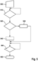
- a branch is preferably made automatically from program point 410 to program point 420 if a predetermined first period of time has passed since the operation of the electric motor, in particular since the start of impact operation of the power tool, even if the conditions of program point 410 are not met.
- the duration of the drive time during impact operation for example, a map, a characteristic curve or a corresponding calculation method is used with which, depending on the standard deviation of the current, and / or depending on the mean standard deviation of the current and / or depending on the standard deviation of the Speed, and / or the drive time is determined as a function of the mean standard deviation of the speed.
- the state of charge of the battery for example, is also taken into account.
- the drive time determined is stored in memory 51.
- the program then branches to program point 450.
- a high speed at program point 440 is required in order to provide a sufficiently high torque for a tool with a large diameter.
- a medium speed at program point 430 ensures that a tool with a smaller diameter does not break off.
- the limit values W, I for the speed and the current are selected accordingly. If the check at program point 510 shows that the speed n is greater than the limit value W and that the current i of the electric motor is greater than the limit value I, then a predefined operating state, in particular impact operation, is recognized and a branch is made to program point 520.
- control circuit 46 outputs a warning signal when the voltage of the battery 19 falls below a predetermined minimum value which is stored in the memory 51. This ensures that the user of the power tool has the option of recharging the battery or adapting the drive time, the rotational speed and / or the torque accordingly in order to achieve a desired drilling result or screwing-in result.
- an electronic clutch is activated before the electric motor is switched off, the torque on the tool is reduced and the electric motor is then switched off.
- the state of charge of the battery is preferably determined each time a program sequence is started, for example by detecting the voltage of the battery.
- Figure 9 shows a further embodiment of the Figure 7 , after program point 720 instead of a simple braking process according to program point 740 of Figure 8 the rotational speed of the electric motor is reduced according to a predetermined speed profile by the control circuit 46 by a corresponding activation of the drive coils 23c and then the electric motor is stopped at a following program point 730.
- the speed profile of program step 750 can consist, for example, in a linear decrease in the speed or in a gradual decrease in the speed of the electric motor 20. Depending on the embodiment selected, other speed profiles can also be used.
- a soft braking process can be used to stop the electric motor at the end of the process.
- the speed of the motor can be reduced or braked to a predetermined low speed.
- the electric motor can be braked until the speed of the electric motor is lower than the mechanical resistance of the electric tool.
- the speed of the electric motor is then gradually reduced to zero. In this way, the motor is braked more quickly to zero speed.
- the electric motor can be braked mechanically or by a corresponding electrical control of the electric motor.
- the trigger 18t is pressed completely to the stop, so that a maximum speed of the electric motor of the power tool is desired by the operator.
- a speed of the actuation of the trigger 18t can also be detected. The speed at which the trigger 18t is actuated can be taken into account in the following automatic methods in addition to or instead of the actuation travel of the trigger 18t.
- the first time period t1 can be between 0.03 and 0.1 seconds, for example. If this is the case, a branch is then made to a following program point 840. If this is not the case, program point 820 continues to be carried out.
- the speed of the electric motor continues to be set as a function of the type of actuation of trigger 18t, as at program point 820.
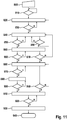
- a following program point 850 it is checked whether the current of the electric motor rises above a predetermined third limit value I3. If this is the case, the counter is increased by the value 1 to the value 1 and a branch is made to a following program point 860. This is the case in the present first operating situation.
- a torque sensor on the power tool can also be used to measure the seating torque of the screw in the initial phase.
- the limit values can be determined or determined by the control circuit as a function of the torque or the seating torque of the screw that occurs when the screw is started to be unscrewed. For example, correspondingly different values for the first, the second, the third and / or the fourth limit value can be stored for predetermined torque ranges. Otherwise, the procedure is carried out according to the first operating situation.
- the electric motor is operated at maximum speed. Subsequently, at program point 950, a check is made as to whether the current of the electric motor exhibits a greater decrease over time than a predefined value.
- the specified value for the temporal drop in the current is stored in the memory. If the query at program point 950 shows that the measured drop over time is less than the specified value, then the program branches back to program point 880. If the query at program point 950 shows that the measured drop over time is greater than the predefined value, the program branches to program point 910. If the drop in current over time is greater than the specified value, this indicates that the screw has been loosened. Program points 910 to 940 are then processed accordingly.
- the program is from Figure 11 Run through as follows: The program starts at program point 800, at which the power tool is put into operation.
- the switch 70 is in the position in which the automatic method for preventing complete loosening of the screw from the workpiece is activated.
- a program point 810 it is then checked whether the power tool is in the operating mode of unscrewing a screw, that is to say, for example, turning it to the left. If this is the case, a counter is set to the value zero at a subsequent program point 820.
- an operator can set a low speed and / or a slow increase in speed for loosening the screw.
- the detection of the rotational speed can be detected on the basis of the type of actuation of the trigger 18t. If the trigger 18t is pressed completely to the stop, a maximum speed of the electric motor is desired by the operator.
- a speed of the actuation of the trigger 18t can also be recorded and, in addition or instead of the actuation path of the trigger 18t, also the speed of the actuation of the trigger 18t in the following automatic method must be taken into account.
- the speed of actuation of the trigger and / or the actuation path of the trigger can be detected with appropriate sensors and passed to the control circuit 46.
- program point 820 is retained until the current is above the first limit value I1.
- the program then branches to program point 840. If the operator reduces the speed of the power tool during program point 840, then the current falls below the second limit value I2, so that the query at program point 890 results in a branch back to program point 820.
- the fourth limit value I4 has a greater value than in the fourth operating situation.
- the query at program point 870 thus shows that the current is less than the fourth limit value. This branches back to program point 840.
- the current is greater than the third limit value I3, so that, according to program point 850, a branch is made to program point 860 again.
- the counter is increased by the value 1 to the value 2.
- the query at program point 870 takes place.
- the query again shows that the current is less than the fourth limit value I4, so that the program then branches back to program point 840.
- the following query at program point 850 again shows that the current is greater than the third limit value is I3, so that the counter is increased by the value 1 to the value 3 and the program branches to program point 860.
- the specified comparison value is stored in the memory as a negative temporal gradient of the current, for example. If the query at program point 950 shows that the measured drop in the current over time is less than the comparison value, a branch is made to program point 910. Program points 910, 920, 930 and 940 are then carried out as described.
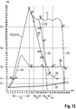
- Figure 12 shows in a diagram the current I over time t for various methods for automatically unscrewing a screw without completely loosening the screw from the workpiece, according to the program sequence of FIG Figure 11 can be carried out.
- a first characteristic curve 73 characterizes the first operating situation.
- a second characteristic curve 74 characterizes the second operating situation.
- a third characteristic curve 75 represents a third operating situation.
- the first three characteristic curves 73, 74, 75 are designed identically for the selected embodiments in an initial phase.
- a fourth characteristic curve 76 represents a fourth operating situation.
- a fifth characteristic curve 77 represents a fifth operating situation.
Description
Die Erfindung betrifft ein Verfahren zum Steuern eines Elektromotors eines Elektrowerkzeuges gemäß Patentanspruch 1.The invention relates to a method for controlling an electric motor of an electric tool according to
Aus dem Stand der Technik ist es bekannt, abhängig von einer Betätigung eines Schalters einen Elektromotor eines Elektrowerkzeuges zu steuern. Dabei wird der Elektromotor beispielsweise mit einer vorgegebenen Drehzahl oder mit einem vorgegebenen Drehmoment angesteuert. Ferner sind Steuerverfahren für Drehschlagschrauber z. B. aus
Die Aufgabe der Erfindung besteht darin, ein verbessertes Verfahren zum Steuern des Elektromotors bereitzustellen.The object of the invention is to provide an improved method for controlling the electric motor.
Die Aufgabe der Erfindung wird durch das Verfahren gemäß Patentanspruch 1 gelöst.The object of the invention is achieved by the method according to
In einer Ausführungsform wird der Elektromotor für eine festgelegte Antriebszeit während eines Schlagbetriebs des Elektrowerkzeuges betrieben und nach der Antriebszeit wird wenigstens ein Drehmoment des Elektromotors oder eine Drehzahl des Elektromotors reduziert. Es kann eine Kupplung verwendet werden, um das Drehmoment am Antrieb zu reduzieren oder der Elektromotor wird abgeschaltet. Beispielsweise wird die elektrische Spannung, mit der der Elektromotor versorgt wird, entsprechend reduziert.In one embodiment, the electric motor is operated for a defined drive time during an impact operation of the electric tool and after the drive time at least one torque of the electric motor or one speed of the electric motor is reduced. A clutch can be used to reduce the torque on the drive or the electric motor can be switched off. For example, the electrical voltage with which the electric motor is supplied is reduced accordingly.
In einer Ausführung kann abhängig von dem erfassten Parameter ein Drehmoment und/oder eine Drehzahl festgelegt werden, mit dem der Elektromotor während des Schlagbetriebes angetrieben wird. Dadurch wird ein verbesserter Einsatz des Elektrowerkzeuges erreicht.In one embodiment, a torque and / or a speed with which the electric motor is driven during the percussion operation can be defined as a function of the detected parameter. This improves the use of the power tool.
Vorzugsweise wird als Parameter eine Standardabweichung des Stromes des Elektromotors und/oder der Drehzahl des Elektromotors während eines Schlagbetriebes des Elektrowerkzeuges erfasst.A standard deviation of the current of the electric motor and / or of the speed of the electric motor during impact operation of the electric tool is preferably recorded as a parameter.
In einer Ausführungsform wird eine Berechnungsmethode und/oder eine Tabelle und/oder eine Kennlinie verwendet werden, um abhängig von dem Parameter die Ansteuerzeit und/oder das Drehmoment und/oder die Drehzahl für die Ansteuerung des Elektromotors festzulegen.In one embodiment, a calculation method and / or a table and / or a characteristic curve are used in order to determine the activation time and / or the torque and / or the speed for the activation of the electric motor as a function of the parameter.
In einer weiteren Ausführungsform wird der Elektromotor mit einer Batterie mit Strom versorgt, wobei eine Spannung der Batterie ermittelt wird, wobei der Parameter mit der ermittelten Batteriespannung bewertet wird, insbesondere wenn die Batteriespannung unter einem Grenzwert liegt. Dadurch kann ein Absinken der Spannung der Batterie durch die Bewertung des Parameters ausgeglichen werden.In a further embodiment, the electric motor is supplied with current by a battery, a voltage of the battery being determined, the parameter being evaluated with the determined battery voltage, in particular if the battery voltage is below a limit value. As a result, a drop in the voltage of the battery can be compensated for by evaluating the parameter.
In einer weiteren Ausführungsform werden die Batteriespannung und die Antriebszeit abhängig von der gemessenen Batteriespannung korrigiert. In einer weiteren Ausführungsform wird die Batteriespannung erfasst, mit einem Referenzwert verglichen und die Antriebszeit wird abhängig von einem Verhältnis der gemessenen Batteriespannung zum Referenzwert korrigiert. Auf diese Weise wird die Größe der Ansteuerung des Elektromotors bei einer veränderlichen Batteriespannung ausgeglichen. Dadurch wird das Antreiben des Elektromotors weiter präzisiert.In a further embodiment, the battery voltage and the drive time are corrected as a function of the measured battery voltage. In a In another embodiment, the battery voltage is detected, compared with a reference value and the drive time is corrected as a function of a ratio of the measured battery voltage to the reference value. In this way, the size of the activation of the electric motor is compensated for when the battery voltage changes. This makes driving the electric motor more precise.
In einer weiteren Ausführungsform wird ein Hinweis an eine Bedienperson ausgegeben, wenn eine gemessene Batteriespannung eine vorgegebene Grenze unterschreitet. Auf diese Weise wird sichergestellt, dass die Bedienperson auf die geringe Batteriespannung und die damit verbundene geringe Antriebsleistung des Elektrowerkzeuges hingewiesen wird. Zudem kann der Hinweis die Information enthalten, dass eine vorgegebene Antriebszeit aufgrund der geringen Batteriespannung angepasst werden sollte. Bei Vorgabe der Antriebszeit durch die Bedienperson hat die Bedienperson aufgrund des Hinweises die Möglichkeit, die Antriebszeit anzupassen, falls sich die Batteriespannung zu stark ändert bzw. unter eine vorgegebene Grenze sinkt.In a further embodiment, a message is output to an operator when a measured battery voltage falls below a predetermined limit. This ensures that the operator is informed of the low battery voltage and the associated low drive power of the power tool. In addition, the note can contain the information that a predefined drive time should be adapted due to the low battery voltage. If the operator specifies the drive time, the operator has the option of adapting the drive time if the battery voltage changes too much or falls below a predetermined limit.
In einer weiteren Ausführungsform wird die Antriebszeit für einen Schlagbetrieb von einer Bedienperson eingegeben. Die Antriebszeit wird abgespeichert und von der Steuerschaltung beim Ansteuern des Elektromotors berücksichtigt. Diese Ausführungsform bietet den Vorteil, dass die Antriebszeit nicht automatisch ermittelt werden muss, sondern dass auf einfache Weise die Bedienperson die Antriebszeit festlegen kann. Die Antriebszeit bezeichnet eine Zeit, die eine Schraube in ein Werkstück während eines Schlagbetriebes eingeschraubt wird, bevor das Drehmoment des Elektromotors reduziert wird, eine Kupplung geöffnet wird oder der Elektromotor vollständig abgeschaltet wird. Auf diese Weise kann eine Beschädigung des Werkzeuges, insbesondere der Schraube vermieden werden. Zudem kann das Werkstück durch Vermeidung eines zu tiefen Eindrehens der Schraube vor Beschädigungen geschützt werden. Insbesondere kann eine Befestigung der Schraube im Werkstück verbessert werden, indem ein Durchdrehen des Gewindes der Schraube im Werkstück durch Festlegung der Antriebszeit während des Schlagbetriebes vermieden wird.In a further embodiment, the drive time for an impact operation is entered by an operator. The drive time is stored and taken into account by the control circuit when driving the electric motor. This embodiment offers the advantage that the drive time does not have to be determined automatically, but that the operator can set the drive time in a simple manner. The drive time denotes a time that a screw is screwed into a workpiece during an impact operation before the torque of the electric motor is reduced, a clutch is opened or the electric motor is completely switched off. In this way, damage to the tool, in particular the screw, can be avoided. In addition, the workpiece can be protected from damage by avoiding the screw being screwed in too deeply. In particular, the fastening of the screw in the workpiece can be improved by preventing the thread of the screw from turning in the workpiece by defining the drive time during the impact operation.
In einer weiteren Ausführungsform wird der Elektromotor gestoppt, wenn ein vorgegebenes Drehmoment beim Herausschrauben einer Schraube unterschritten wird. Das zu geringe Drehmoment zeigt eine gelockerte Schraube an. Auf diese Weise wird erreicht, dass die gelockerte Schraube nicht vollständig aus dem Werkstück herausgeschraubt wird, sondern noch im Werkstück stecken bleibt. Damit ist die Gefahr vermindert, dass die Schraube verloren geht.In a further embodiment, the electric motor is stopped when the torque falls below a predetermined value when a screw is unscrewed. The insufficient torque indicates a loosened screw. In this way it is achieved that the loosened screw is not completely screwed out of the workpiece, but remains stuck in the workpiece. This reduces the risk of the screw being lost.
In einer Ausführungsform wird das abgegebene Drehmoment anhand eines Wertes eines Stromes erfasst, der vom Elektromotor aufgenommen wird, wobei der Elektromotor gestoppt wird, wenn der Wert des Stromes unter einen vorgegebenen Grenzwert fällt. Die geringe Stromaufnahme zeigt an, dass sich die Schraube leicht drehen lässt, d.h. nur schon locker sitzt.In one embodiment, the output torque is detected on the basis of a value of a current that is consumed by the electric motor, the electric motor being stopped when the value of the current falls below a predetermined limit value. The low power consumption indicates that the screw can be turned easily, i.e. it is only loosely seated.
In einer Ausführungsform wird beim Herausschrauben einer Schraube der Elektromotor gestoppt wird, wenn die Schraube nach einer Aktivierung des Elektromotors eine vorgegebene Anzahl von Umdrehungen aus einer Sitzposition herausgeschraubt wurde. Vorzugsweise kann die Anzahl der Umdrehungen von einer Bedienperson beispielsweise durch eine Eingabe festgelegt werden. Damit wird zusätzlich die Gefahr vermindert, dass die Schraube beim Herausschrauben verloren geht. Zudem wird die Handhabung des Elektrowerkzeuges verbessert.In one embodiment, when a screw is unscrewed, the electric motor is stopped if the screw has been unscrewed a predetermined number of revolutions from a seated position after the electric motor has been activated. The number of revolutions can preferably be determined by an operator, for example by means of an input. This also reduces the risk of the screw being lost when it is unscrewed. In addition, the handling of the power tool is improved.
Eine weitere Ausführungsform betrifft ein Verfahren zum Steuern eines Elektromotors eines Elektrowerkzeuges mit einer Aufnahme für ein Werkzeug zum Herausschrauben einer Schraube von einem Gegenstück, wobei abhängig von einem Sitzmoment der Schraube unterschiedliche Steuerverfahren zum Herausschrauben der Schraube oder des Werkstückes verwendet werden.Another embodiment relates to a method for controlling an electric motor of a power tool with a receptacle for a tool for unscrewing a screw from a counterpart, different control methods being used to unscrew the screw or the workpiece depending on a seating torque of the screw.
In einer weiteren Ausführungsform werden abhängig von einer durch eine Bedienperson vorgegebenen Drehzahl des Elektromotors und/oder abhängig von einer Geschwindigkeit einer Betätigung eines Schalters zum Vorgeben der Drehzahl verschiedene Steuerverfahren zum Herausdrehen der Schraube gewählt werden.In a further embodiment, different control methods for unscrewing the screw can be selected depending on a speed of the electric motor specified by an operator and / or depending on a speed of actuation of a switch for specifying the speed.
In einer weiteren Ausführungsform wird der Elektromotor in einer ersten Phase gemäß einer vorgegebenen Drehzahl angesteuert, wobei der Strom des Elektromotors während der ersten Phase erfasst wird, wobei der erfasste Strom mit einem Grenzwert verglichen wird, wobei bei Überschreiten des Grenzwertes der Elektromotor während einer folgenden zweiten Phase mit einer vorgegebenen zweiten Drehzahl angesteuert wird, wobei der Strom des Elektromotors während der zweiten Phase erfasst wird, wobei abhängig von dem erfassten Strom der zweiten Phase eine gelöste Schraube erkannt wird und die Drehzahl des Elektromotors wenigstens reduziert oder gestoppt wird, und wobei der Grenzwert von dem Sitzmoment und/oder von der durch die Bedienperson vorgegebenen Drehzahl abhängt.In a further embodiment, the electric motor is controlled in a first phase according to a predetermined speed, the current of the electric motor is detected during the first phase, wherein the detected current is compared with a limit value, wherein when the limit value is exceeded, the electric motor is controlled during a subsequent second phase with a predetermined second speed, the current of the electric motor being detected during the second phase, wherein depending on the detected current of the second phase, a loosened screw is detected and the speed of the electric motor is at least reduced or stopped, and the limit value depends on the seat torque and / or on the speed specified by the operator.
In einer Ausführungsform wird der Elektromotor in einer ersten Phase gemäß einer von einer Bedienperson vorgegebenen Drehzahl angesteuert, wobei eine Zeitdauer insbesondere mithilfe eines Zählers erfasst wird, während der der Elektromotor in der ersten Phase verweilt, wobei bei Überschreiten einer vorgegebenen Zeitdauer, insbesondere eines Zählerstandes, der Elektromotor während einer folgenden zweiten Phase mit einer vorgegebenen zweiten Drehzahl, insbesondere mit einer maximalen Drehzahl angesteuert wird, wobei der Strom des Elektromotors während der zweiten Phase erfasst wird, wobei abhängig von dem erfassten Strom des Elektromotors während der zweiten Phase eine gelöste Schraube erkannt wird und die Drehzahl des Elektromotors wenigstens reduziert oder der Elektromotor gestoppt wird.In one embodiment, the electric motor is controlled in a first phase according to a speed specified by an operator, a period of time being recorded, in particular with the aid of a counter, during which the electric motor remains in the first phase. the electric motor is controlled with a predetermined second speed, in particular with a maximum speed, during a subsequent second phase, the current of the electric motor being recorded during the second phase, with a loosened screw being detected depending on the recorded current of the electric motor during the second phase and the speed of the electric motor is at least reduced or the electric motor is stopped.
In einer weiteren Ausführungsform wird abhängig von einem Unterschreiten eines vorgegebenen Stromgrenzwertes und/oder abhängig von einem Überschreiten eines vorgegebenen negativen zeitlichen Gradienten eine gelöste Schraube erkannt und die Drehzahl des Elektromotors wenigstens reduziert oder der Elektromotor gestoppt.In a further embodiment, depending on whether a predetermined current limit value is not reached and / or depending on whether a predetermined negative time gradient is exceeded, a loosened screw is recognized and the speed of the electric motor is at least reduced or the electric motor is stopped.
In einer weiteren Ausführung wird das Sitzmoment der Schraube anhand des Stromes abgeschätzt, der vom Elektromotor aufgenommen wird.In a further embodiment, the seating torque of the screw is estimated on the basis of the current that is absorbed by the electric motor.
Die beschriebenen Verfahren können auch auf das Herausschrauben von Schraubenbolzen oder Schraubenmuttern oder anderen geschraubten Teilen angewendet werden.The methods described can also be applied to unscrewing bolts or nuts or other screwed parts.
Die Erfindung wird im Folgenden anhand der Figuren näher erläutert. Es zeigen
Figur 1- einen schematischen Querschnitt durch ein Elektrowerkzeug,
Figur 2- einen zweiten Querschnitt durch das Elektrowerkzeug,
Figur 3- eine schematische Darstellung einer Schaltungsanordnung zum Antreiben eines Elektromotors eines Elektrowerkzeuges,
Figur 4- einen ersten schematischen Programmablauf zum Betreiben des Elektrowerkzeuges,
Figur 5- einen zweiten schematischen Programmablauf zum Betreiben des Elektrowerkzeuges,
Figur 6- einen dritten schematischen Programmablauf zum Betreiben des Elektrowerkzeuges,
Figur 7- einen vierten schematischen Programmablauf zum Betreiben des Elektrowerkzeuges,
Figur 8- einen fünften schematischen Programmablauf zum Betreiben des Elektrowerkzeuges,
Figur 9- einen sechsten schematischen Programmablauf zum Betreiben des Elektrowerkzeuges,
Figur 10- in einer schematischen Darstellung einen zeitlichen Verlauf des Stromes I für den Elektromotor bei einem Herausdrehen einer Schraube,
Figur 11- in einer schematischen Darstellung einen Programmablauf, mit dem eine Beeinflussung des Herausdrehens einer Schraube aus einem Werkstück erfolgt, und
Figur 12- in einem Diagramm den Strom I über die Zeit t für verschiedene Verfahren zum automatischen Herausdrehen einer Schraube.
- Figure 1
- a schematic cross section through a power tool,
- Figure 2
- a second cross-section through the power tool,
- Figure 3
- a schematic representation of a circuit arrangement for driving an electric motor of a power tool,
- Figure 4
- a first schematic program sequence for operating the power tool,
- Figure 5
- a second schematic program sequence for operating the power tool,
- Figure 6
- a third schematic program sequence for operating the power tool,
- Figure 7
- a fourth schematic program sequence for operating the power tool,
- Figure 8
- a fifth schematic program sequence for operating the power tool,
- Figure 9
- a sixth schematic program sequence for operating the power tool,
- Figure 10
- a schematic representation of a time profile of the current I for the electric motor when a screw is unscrewed,
- Figure 11
- a schematic representation of a program sequence with which the unscrewing of a screw from a workpiece is influenced, and
- Figure 12
- in a diagram the current I over time t for various methods for automatically unscrewing a screw.
Der Griff 15 des Gehäuses 11 wird von einer Bedienperson umfasst, um das Elektrowerkzeug 10 zu benutzen. Der Griff weist einen Halteabschnitt 15h und einen unteren Endabschnitt 15p auf, der sich am unteren Ende des Griffabschnittes 15h anschließt. Am unteren Endabschnitt 15p ist die Batterie 19 vorgesehen, die das Elektrowerkzeug 10 mit Strom versorgt. Am Griffabschnitt 15h ist ein Hauptschalter 18 vorgesehen, der einen Trigger 18t aufweist, der mit einem Finger betätigt werden kann. Weiterhin weist der Hauptschalter 18 eine Schaltereinheit 18s auf, die zum Einschalten oder Ausschalten des Elektrowerkzeuges verwendet wird. Der Trigger 18t wird dazu verwendet, um in Abhängigkeit vom Betätigungsweg des Triggers 18t eine Größe der Ansteuerung des Elektromotors 20 zu erhöhen. Der Trigger stellt einen Schalter zum vorgeben der Drehzahl des Elektromotors dar. Der Betätigungsweg des Triggers 18t wird beispielsweise mithilfe der Schaltereinheit 18s beispielsweise als Widerstandswert erfasst und an eine Steuerschaltung (46,
Weiterhin ist oberhalb des Hauptschalters 18 ein Richtungsschalter 17 vorgesehen, der abhängig von einer Position die Drehrichtung der Aufnahme 27t festlegt. Der Richtungsschalter 17 kann als Schiebeschalter oder als Drehschalter ausgebildet sein. In einer ersten Position des Richtungsschalters 17 dreht das Elektrowerkzeug 10 bei gleichzeitiger Betätigung des Hauptschalters 18 in einer Rechtsrichtung im Uhrzeigersinn, d. h. im Normalbetrieb z.B. zum Einschrauben einer Schraube. In einer zweiten Position des Richtungsschalters 17 und bei gleichzeitiger Betätigung des Hauptschalters 18 dreht das Elektrowerkzeug 10 in einer Linksrichtung, d. h. entgegen dem Uhrzeigesinn in einem Herausschraubbetrieb bzw. Lösebetrieb zum Herausschrauben bzw. zum Lösen einer Schraube.Furthermore, a
Zudem kann das Elektrowerkzeug einen Schalter 70 aufweisen. Der Schalter 70 kann als Dreh - oder Schiebeschalter ausgebildet sein. Die Position des Schalters 70 wird an die Steuerschaltung (46,
An einer vorderen Endfläche des Hammers 26h sind Schlagvorsprünge 26w ausgebildet, um Schläge auf den Amboss 27 an zwei um 180° zueinander versetzten Stellen zu erzeugen. Weiterhin hat der Amboss 27 an den zwei um 180° versetzten Stellen in Umfangsrichtung Schlagarme 27d (
Die Schraube kann beim Eindrehen eine Position im Werkstück erreichen, an der ein Einschraubwiderstand das Drehmoment des Hammers 26h übersteigt. Der Einschraubwiderstand wird als Drehmoment auf den Amboss 27 übertragen. Als Ergebnis wird der Hammer 26h gegen die Vorspannkraft der Druckfeder 26b von der Spindel zurück versetzt und die Schlagvorsprünge 26w des Hammers überstreichen die Schlagarme 27d des Ambosses 27. Dabei werden die Schlagvorsprünge 26w von der Anlage an den Schlagarmen 27d befreit, sodass sich die Schlagvorsprünge 26w einen festgelegten Winkel frei drehen können. Wenn sich die Schlagvorsprünge 26w des Hammers 26h über die Schlagarme 27d des Ambosses 27 bewegen, dann beschleunigt der Hammer seine Drehbewegung. Durch die Vorspannkraft der Druckfeder 26b wird der Hammer 26h innerhalb des festgelegten Winkels wieder in Richtung auf den Amboss 27 gedrückt, sodass die Schlagvorsprünge 26w des Hammers wieder in Kontakt gelangen mit den Schlagarmen 27d des Ambosses 27. Durch den Aufschlag der Schlagvorsprünge 26w auf die Schlagarme 27d wird ein erhöhtes Drehmoment auf den Amboss 27 und damit auf die Aufnahme 27t und die Schraube 61 bzw. den Bohrer 60 ausgeübt. Dieser Vorgang wird während des Schlagbetriebes laufend wiederholt.When screwing in, the screw can reach a position in the workpiece at which a screw-in resistance exceeds the torque of the
Zudem kann das Elektrowerkzeug 10 eine Eingabeeinheit 50 aufweisen, mit der ein Benutzer des Elektrowerkzeuges beispielsweise die maximale Antriebszeit für den Elektromotor, insbesondere die maximale Antriebszeit des Elektromotors für einen Schlagbetrieb eingeben kann. Zudem kann ein Benutzer ein Parameter für eine Größe des Werkzeuges, insbesondere einen Durchmesser für eine Schraube oder einen Bohrer eingeben. Die Eingabeeinheit 50 ist mit der elektronischen Steuerschaltung (46,
Die Dreiphasenbrückenschaltung 45 hat drei Ausgangsleitungen 41, die mit den entsprechenden Steuerspulen 23c des Elektromotors 20 verbunden sind. Die Steuerschaltung 46 ist ausgebildet, um die Schaltelemente 44 basierend auf Signalen von magnetischen Sensoren 32 in der Weise anzusteuern, dass ein elektrischer Strom sequentiell durch die Antriebsspulen 23c fließt, um den Rotor 22 mit einer gewünschten Drehzahl und/oder einem gewünschten Drehmoment zu drehen. Zudem kann die Steuerschaltung 46 mithilfe der magnetischen Sensoren 32 eine Drehzahl des Elektromotors 20 messen. Weiterhin steht die Steuerschaltung 46 mit einer Messeinrichtung 53 in Verbindung, die den Ladezustand der Batterie 19, insbesondere die Spannung der Batterie 19 erfasst und an die Steuerschaltung 46 weitergibt. Die Steuerschaltung 46 ist mit dem Schalter 70 verbunden.The three-
Zudem weist das Elektrowerkzeug eine Eingabeeinheit 50 auf, mit der ein Benutzer des Elektrowerkzeuges beispielsweise die maximale Antriebszeit für einen Schlagbetrieb und/oder eine Größe, insbesondere einen Durchmesser für eine Schraube oder einen Bohrer eingeben kann. Die Eingabeeinheit 50 ist mit der elektronischen Steuerschaltung 46 verbunden. Zudem ist die elektronische Steuerschaltung 46 mit einem Speicher 51 verbunden. Im Speicher 51 sind Daten, Kennlinien, Kennfelder und/oder Berechnungsmethoden abgelegt. Weiterhin verfügt das Elektrowerkzeug über eine Ausgabe 52, über die ein Signal an den Benutzer, insbesondere ein Warnsignal über einen zu niedrigen Ladezustand der Batterie abgegeben werden kann. Dazu ist ein Grenzwert für den Ladezustand der Batterie im Speicher 51 abgelegt. Die Steuerschaltung 46 erfasst mithilfe der Messeinrichtung 53 die aktuelle Spannung der Batterie 19 und vergleicht die gemessene Spannung mit dem Grenzwert. Unterschreitet der Ladezustand der Batterie 19 den Grenzwert, dann gibt die Steuerschaltung 46 einen entsprechenden Hinweis optisch, akustisch und/oder haptisch über die Ausgabe 52 aus. Weiterhin kann der Benutzer durch eine entsprechende Eingabe den automatischen Betrieb des Elektromotors 20 abschalten.In addition, the power tool has an
Zudem kann die Steuerschaltung 46 einen Typ der Batterie 19, der beispielsweise durch einen Code auf der Batterie mitgeteilt wird, beispielsweise mithilfe eines Sensors, insbesondere mithilfe eines optischen Sensors erfassen. Der Typ der Batterie 19 legt fest, welche Batteriespannung einem ausreichenden Ladezustand entspricht. Im Speicher 51 kann für verschiedene Codes bzw. Typen von Batterien entsprechende Grenzwerte für die Spannung abgelegt sein, die einer ausreichenden Ladung der Batterie 19 für einen normalen Betrieb, insbesondere für einen Schlagbetrieb entspricht. Zum Festlegen des Ladezustandes misst die Steuerschaltung 46 mithilfe der Messeinrichtung 53 die Ladespannung der Batterie 19 und vergleicht diese mit abgespeicherten Grenzwerten. Vorzugsweise kann dabei der Typ der Batterie berücksichtigt werden, um präzise Grenzwerte für einen ausreichenden Ladezustand der Batterie 19 aus dem Speicher 51 auszulesen. Weiterhin kann die Steuerschaltung 46 den Strom des Elektromotors 20 mit einem Strommesser 54 und/oder die Drehzahl des Elektromotors 20 mit einem Drehzahlmesser 29 messen. Der Strom und/oder die Drehzahl können von der Steuerschaltung 46 verwendet werden, um festzustellen, wann ein Schlagbetrieb des Elektrowerkzeuges beginnt. Dazu sind entsprechende Schwellen bzw. Grenzwerte für den Strom des Elektromotors und die Drehzahl des Elektromotors im Speicher 51 abgelegt, die der Elektromotor 20 überschreitet, wenn ein Schlagbetrieb startet. Die Steuerschaltung 46 ist ausgebildet, um abhängig von einem erfassten Parameter des Elektromotors, insbesondere abhängig vom Strom und/oder von der Drehzahl eine Antriebszeit für einen Schlagbetrieb zu bestimmen. Dabei wird vorzugsweise auch der Ladezustand der Batterie berücksichtigt. Für die Bestimmung der Antriebszeit wird ein Kennfeld, eine Kennlinie, eine Tabelle oder entsprechendes Berechnungsverfahren verwendet. Das Kennfeld, die Kennlinie, die Tabelle oder das Berechnungsverfahren bestimmen einen Zusammenhang zwischen dem Strom und/oder der Drehzahl und der Antriebszeit. Am Ende der Antriebszeit, d. h. am Ende des Schlagbetriebes wird der Elektromotor 20 von der Steuerschaltung 46 gestoppt oder es wird eine elektronische Kupplung für eine kurze Zeitdauer aktiviert und anschließend wird der Elektromotor vollständig gestoppt. Der ermittelte Parameter für die Größe des Werkzeuges, insbesondere der Durchmesser des Bohrers und/oder der Schraube wird im Speicher abgelegt und für weitere Bohr- oder Schraubvorgänge von der Steuerschaltung 46 verwendet.In addition, the
In einer ersten Ausführungsform, die anhand eines ersten Programmablaufes der
Zudem kann die Ermittlung der Größe der Ansteuerung des Elektromotors auf zwei weitere Wege ermittelt werden. Ein erster Berechnungsweg ermittelt eine Standardabweichung der gemessenen Werte für den Strom und/oder eine Standardabweichung der gemessenen Werte für die Drehzahl während der ersten Zeitdauer während einer Ansteuerung des Elektromotors, insbesondere während der ersten 200 Millisekunden nach einem Beginn eines Schlagbetriebes des Elektrowerkzeuges 10.In addition, the size of the activation of the electric motor can be determined in two further ways. A first calculation method determines a standard deviation of the measured values for the current and / or a standard deviation of the measured values for the speed during the first period of time during activation of the electric motor, in particular during the first 200 milliseconds after the start of impact operation of the
Die Standardabweichung kann nach folgenden Formeln berechnet werden:
Die Standardabweichung σx einer Zufallsvariablen Xist definiert als die Quadratwurzel der Varianz Var(X): ![]()
The standard deviation σ x of a random variable X is defined as the square root of the variance Var ( X ):![]()
Dabei ist die Varianz ![]()
![]()
Bei einer zweiten Berechnungsart wird die erste Zeitdauer in eine vorgegebene Anzahl von Teilintervallen unterteilt, beispielsweise in zehn Teilintervalle. Anschließend wird für jedes Teilintervall für die gemessenen Werte für den Strom eine Standardabweichung und/oder die Drehzahl eine Standardabweichung berechnet. Anschließend wird aus den zehn Standardabweichungen für den Strom und/oder die Drehzahl durch eine Mittelwertbildung eine gemittelte Standardabweichung für den Strom und/oder eine gemittelte Standardabweichung für die Drehzahl ermittelt.In a second type of calculation, the first time period is divided into a predetermined number of sub-intervals, for example into ten sub-intervals. A standard deviation and / or a standard deviation for the speed is then calculated for each sub-interval for the measured values for the current. Subsequently, an averaged standard deviation for the current and / or an averaged standard deviation for the speed is determined from the ten standard deviations for the current and / or the speed by averaging.
Die Standardabweichung und/oder die gemittelte Standardabweichung der Drehzahl und/oder des Stromes werden dazu verwendet, um anhand von Tabellen eine Größe für eine Ansteuerung des Elektromotors zu ermitteln. Anstelle einer Tabelle kann auch eine andere Berechnungsmethode und/oder eine Kennlinie verwendet werden, um die Größe für die Ansteuerung des Elektromotors zu ermitteln.The standard deviation and / or the averaged standard deviation of the speed and / or the current are used to determine a variable for controlling the electric motor on the basis of tables. Instead of a table, another calculation method and / or a characteristic curve can also be used to determine the variable for controlling the electric motor.
Die Größe kann beispielsweise eine Antriebszeit zum Ansteuern des Elektromotors sein. Beispielsweise kann die Antriebszeit die Zeit festlegen, die der Elektromotor angetrieben wird, wenn der Taster gedrückt wird, um eine Schraube einzuschrauben. Nach der Antriebszeit wird die Spannungsversorgung des Elektromotors 20 reduziert oder abgebrochen. Die Antriebszeit ist die Zeit, die der Elektromotor während eines Schlagbetriebes des Elektrowerkzeuges angetrieben wird, um insbesondere eine Schraube in ein Werkstück einzuschrauben. Zudem kann die Größe der Ansteuerung des Elektromotors eine maximale Drehzahl und/oder ein maximales Drehmoment und/oder einen maximalen Strom betreffen.The variable can, for example, be a drive time for controlling the electric motor. For example, the drive time can determine the time that the electric motor is driven when the button is pressed to screw in a screw. After the drive time, the voltage supply of the
Das Programm startet bei Programmpunkt 400. Bei einem folgenden Programmpunkt 410 wird überprüft, ob die Drehzahl n über einem vorgegebenen Grenzwert W liegt, und ob der Strom i über einem vorgegebenen Grenzwert I liegt. Sind beide Bedingungen nicht erfüllt, so wird der Programmpunkt 410 erneut durchlaufen. Ergibt die Abfrage, dass die Drehzahl n größer als der Grenzwert W ist und dass der Strom i des Elektromotors größer als der Grenzwert I ist, so wird zu Programmpunkt 420 verzweigt. Durch die Abfrage bei Programmpunkt 410 wird überprüft, ob sich das Elektrowerkzeug bereits in einem festgelegten Betriebszustand, z.B. im Schlagbetrieb befindet, in dem der Hammer immer wieder auf den Amboss schlägt. Entsprechende Grenzwerte W,I sind für die Drehzahl und den Strom festgelegt und im Speicher 51 abgelegt. Nach Erkennen des vorgegebenen Betriebszustandes wird die Antriebszeit für eine Ansteuerung des Elektromotors, insbesondere für einen Schlagbetrieb des Elektrowerkzeuges gestartet.The program starts at
Beispielsweise kann überprüft werden, ob ein Schlagbetrieb vorliegt, indem eine Zeitdauer zwischen zwei Schlägen des Schlagbetriebes kleiner als ein erster Grenzwert ist. Der erste Grenzwert kann im Bereich zwischen 0,01 Sekunde und 0,05 Sekunden liegen. Der erste Grenzwert ist im Speicher 51 abgelegt. Die Schläge können beispielsweise anhand von Schallsensoren akustisch erfasst werden oder anhand des zeitlichen Verlaufes des Stroms durch den Elektromotor ermittelt werden. Zudem kann überprüft werden, ob eine Standardabweichung der gemessenen Drehzahl kleiner als ein zweiter Grenzwert ist. Der zweite Grenzwert kann im Bereich zwischen 30 und 90 liegen. Der zweite Grenzwert ist im Speicher 51 abgelegt. Wenn beide Bedingungen erfüllt sind, ist eindeutig ein Schlagbetrieb des Elektrowerkzeuges erkannt. Die Grenzwerte werden experimentell ermittelt und können von Elektrowerkzeug zu Elektrowerkzeug z.B. abhängig von der Art des Elektromotors variieren.For example, it can be checked whether an impact operation is present in that a period of time between two impacts of the impact operation is less than a first limit value. The first limit value can be in the range between 0.01 seconds and 0.05 seconds. The first limit value is stored in
Zudem wird vorzugsweise automatisch von Programmpunkt 410 zu Programmpunkt 420 verzweigt, wenn eine vorgegebene erste Zeitdauer seit Betrieb des Elektromotors, insbesondere seit dem Beginn des Schlagbetriebes des Elektrowerkzeuges vergangen ist, auch wenn die Bedingungen von Programmpunkt 410 nicht erfüllt sind.In addition, a branch is preferably made automatically from
Bei Programmpunkt 420 wird abhängig von den gemessenen Werten für den Strom und/oder den gemessenen Werten für die Drehzahl des Elektromotors während einer ersten Zeitdauer im Programmpunkt 420 wenigstens ein Parameter des Elektromotors ermittelt. Als Parameter werden z.B. der Strom und/oder die Drehzahl des Elektromotors in festgelegten Zeitabständen während der ersten Zeitdauer gemessen. Die erste Zeitdauer kann z.B. von einem Start des Schlagbetriebes bis zu 200 Millisekunden nach dem Start des Schlagbetriebes dauern. Der ermittelte Strom und/oder die ermittelte Drehzahl und/oder die Standardabweichung der Drehzahl und/oder des Stromes und/oder die gemittelte Standardabweichung der Drehzahl und/oder des Stromes werden, wie oben beschrieben berechnet und dazu verwendet, um anhand von Tabellen eine Größe für eine Ansteuerung des Elektromotors zu ermitteln. Anstelle einer Tabelle kann auch eine andere Berechnungsmethode und/oder eine Kennlinie verwendet werden, um die Größe für die Ansteuerung des Elektromotors zu ermitteln.At
Beispielsweise wird abhängig von dem Parameter als Größe eine Antriebszeit des Elektromotors während eines Schlagbetriebes festgelegt, wobei bei Aktivierung des Elektrowerkzeuges, insbesondere durch eine Betätigung eines Schalters der Elektromotor für die festgelegte Antriebszeit angetrieben wird, um z.B. eine Schraube in ein Werkstück im Schlagbetrieb einzuschrauben. Die Antriebszeit kann um die erste Zeitdauer verlängert sein, da erst nach der ersten Zeitdauer die Antriebszeit berechnet wird.For example, depending on the parameter, a drive time of the electric motor during impact operation is specified, with the electric motor being driven for the specified drive time when the power tool is activated, in particular by actuating a switch, in order, for example, to screw a screw into a workpiece in impact operation. The drive time can be extended by the first time period, since the drive time is only calculated after the first time period.
Zudem kann abhängig von dem Parameter als Größe ein Drehmoment und/oder eine Drehzahl festgelegt werden, mit denen der Elektromotor bei Aktivierung des Elektrowerkzeuges, insbesondere bei Betätigung eines Schalters im Schlagbetrieb angetrieben wird. In einer Ausführung sind dazu entsprechende Tabellen, Kennlinien oder Formeln abgelegt, um abhängig von dem erfassten Parameter Werte für den Strom und/oder die Drehzahl des Elektromotors während des Schlagbetriebes des Elektrowerkzeuges zu ermitteln.In addition, depending on the parameter, a torque and / or a speed with which the electric motor is driven when the electric tool is activated, in particular when a switch is operated in impact mode, can be specified as a variable. In one embodiment, corresponding tables, characteristic curves or formulas are stored for this purpose in order to determine values for the current and / or the speed of the electric motor during the percussion operation of the electric tool as a function of the detected parameter.
Weiterhin kann der erfasste Parameter abhängig von einer Batteriespannung des Elektrowerkzeuges bewertet werden, insbesondere wenn die Batteriespannung unter einem vorgegebenen Grenzwert liegt.Furthermore, the recorded parameter can be evaluated as a function of a battery voltage of the power tool, in particular if the battery voltage is below a predetermined limit value.
Beispielsweise werden als Parameter eine Standardabweichung des Stroms, und/oder eine mittlere Standardabweichung des Stroms und/oder eine Standardabweichung der Drehzahl, und/oder eine mittlere Standardabweichung der Drehzahl verwendet. Zudem kann der Parameter mit dem Ladezustand der Batterie bewertet werden, bevor eine Größe der elektrischen Steuerung des Elektromotors abhängig von dem Parameter bzw. von dem bewerteten Parameter festgelegt wird.For example, a standard deviation of the current and / or a mean standard deviation of the current and / or a standard deviation of the speed and / or a mean standard deviation of the speed are used as parameters. In addition, the parameter with the state of charge of the battery can be evaluated before a variable of the electrical control of the electric motor is determined depending on the parameter or the evaluated parameter.
Zudem kann die Antriebszeit beispielsweise während des Schlagbetriebes von dem Parameter, d.h. in Abhängigkeit von der Standardabweichung des Stroms, und/oder in Abhängigkeit von der mittleren Standardabweichung des Stroms und/oder in Abhängigkeit von der Standardabweichung der Drehzahl, und/oder in Abhängigkeit von der mittleren Standardabweichung der Drehzahl ermittelt werden. Beispielsweise wird bei der Bestimmung der Antriebszeit auch der Ladezustand der Batterie berücksichtigt. Zur Ermittlung der Antriebszeit, d. h. der Dauer der Antriebszeit während eines Schlagbetriebes wird beispielsweise ein Kennfeld, eine Kennlinie oder ein entsprechendes Berechnungsverfahren verwendet, mit dem in Abhängigkeit von der Standardabweichung des Stroms, und/oder in Abhängigkeit von der mittleren Standardabweichung des Stroms und/oder in Abhängigkeit von der Standardabweichung der Drehzahl, und/oder in Abhängigkeit von der mittleren Standardabweichung der Drehzahl die Antriebszeit ermittelt wird. Zudem wird beispielsweise der Ladezustand der Batterie berücksichtigt. Die ermittelte Antriebszeit wird im Speicher 51 abgelegt.In addition, the drive time can, for example, during impact operation from the parameter, ie depending on the standard deviation of the current, and / or depending on the mean standard deviation of the current and / or depending on the standard deviation of the speed, and / or depending on the mean standard deviation of the speed can be determined. For example, the state of charge of the battery is also taken into account when determining the drive time. To determine the drive time, i. H. the duration of the drive time during impact operation, for example, a map, a characteristic curve or a corresponding calculation method is used with which, depending on the standard deviation of the current, and / or depending on the mean standard deviation of the current and / or depending on the standard deviation of the Speed, and / or the drive time is determined as a function of the mean standard deviation of the speed. The state of charge of the battery, for example, is also taken into account. The drive time determined is stored in
Beispielsweise kann die Steuerschaltung 46 überprüfen, ob während einer ersten Zeitdauer bei Programmpunkt 420 die Standardabweichung des Stroms größer als ein erster Grenzwert X1 ist und/oder ob die Standardabweichung der Drehzahl größer als ein erster Grenzwert Y1 ist .Sind diese Bedingungen nicht erfüllt, so wird zu Programmpunkt 430 verzweigt und der Elektromotor 20 wird mit einer mittleren Drehzahl angetrieben.For example, the
Beispielsweise kann die Steuerschaltung 46 überprüfen, ob während einer ersten Zeitdauer bei Programmpunkt 420 die mittlere Standardabweichung des Stroms größer als ein zweiter Grenzwert X2 ist, und/oder ob die mittlere Standardabweichung der Drehzahl größer als ein zweiter Grenzwert Y2 ist. Sind beide Bedingungen nicht erfüllt, so wird zu Programmpunkt 430 verzweigt und der Elektromotor 20 wird mit einer mittleren Drehzahl angetrieben.For example, the
Werden die Abfragen bei Programmpunkt 420 erfüllt, so wird zu Programmpunkt 440 verzweigt und der Elektromotor 20 wird mit einer hohen Drehzahl angetrieben.If the inquiries at
Anschließend wird zu Programmpunkt 450 verzweigt. Eine hohe Geschwindigkeit bei Programmpunkt 440 ist erforderlich, um für ein Werkzeug mit einem großen Durchmesser ein ausreichend hohes Drehmoment bereitzustellen. Wohingegen eine mittlere Geschwindigkeit bei Programmpunkt 430 dafür sorgt, dass ein Werkzeug mit einem kleineren Durchmesser nicht abbricht.The program then branches to
Bei Programmpunkt 450 wird überprüft, ob die ermittelte Antriebszeit des Elektromotors während des Schlagbetriebes des Elektrowerkzeuges erreicht wurde. Ist dies der Fall, so wird bei Programmpunkt 460 das Drehmoment des Elektromotors reduziert bzw. eine Kupplung geöffnet oder der Elektromotor abgeschaltet. Auch bei einem Betrieb mit einer mittleren Geschwindigkeit bzw. Drehzahl des Antriebes gemäß Programmpunkt 430 wird bei Programmpunkt 450 überprüft, ob die ermittelte Antriebszeit während des Schlagbetriebes des Elektrowerkzeuges erreicht wurde. Ist dies der Fall, so wird bei Programmpunkt 460 das Drehmoment des Elektromotors reduziert bzw. eine Kupplung geöffnet oder der Elektromotor abgeschaltet.At
Abhängig von der gewählten Ausführungsform können auch andere Verfahren oder Berechnungsmethoden verwendet werden, um abhängig vom Strom und/oder der Drehzahl eine während des Schlagbetriebes des Elektrowerkzeuges eine Größe für die Ansteuerung des Elektromotors, insbesondere eine Antriebszeit für den Schlagbetrieb zu ermitteln. Zudem kann abhängig von der gewählten Ausführung auf die unterschiedlichen Drehzahlen verzichtet werden und der Elektromotor während des Schlagbetriebes mit einer vorgegebenen Drehzahl und/oder mit einem vorgegebenen Drehmoment betrieben werden.Depending on the selected embodiment, other methods or calculation methods can also be used to determine a variable for the control of the electric motor, in particular a drive time for the percussion operation, depending on the current and / or the speed of rotation. In addition, depending on the selected design, the different speeds can be dispensed with and the electric motor can be operated at a predetermined speed and / or with a predetermined torque during impact operation.
In einer weiteren Ausführung kann überprüft werden, ob ein Schlagbetrieb vorliegt, indem eine Zeitdauer zwischen zwei Schlägen des Schlagbetriebes kleiner als ein erster Grenzwert ist. Der erste Grenzwert kann im Bereich zwischen 0,01 Sekunde und 0,05 Sekunden liegen. Der erste Grenzwert ist im Speicher 51 abgelegt. Die Schläge können beispielsweise anhand von Schallsensoren akustisch erfasst werden oder anhand des zeitlichen Verlaufes des Stroms durch den Elektromotor ermittelt werden. Zudem kann überprüft werden, ob eine Standardabweichung der gemessenen Drehzahl kleiner als ein zweiter Grenzwert ist. Der zweite Grenzwert kann im Bereich zwischen 30 und 90 liegen. Der zweite Grenzwert ist im Speicher 51 abgelegt. Wenn beide Bedingungen erfüllt sind, ist eindeutig ein Schlagbetrieb des Elektrowerkzeuges erkannt. Die Grenzwerte werden experimentell ermittelt und können von Elektrowerkzeug zu Elektrowerkzeug z.B. abhängig von der Art des Elektromotors variieren.In a further embodiment, it can be checked whether an impact operation is present in that a period of time between two impacts of the impact operation is less than a first limit value. The first limit value can be in the range between 0.01 seconds and 0.05 seconds. The first limit value is stored in
Bei Programmpunkt 520 wird abhängig von der eingegebenen Größe des Werkzeuges eine Antriebszeit für den Elektromotor ermittelt. Zur Ermittlung der Antriebszeit, d. h. der Dauer der Antriebszeit wird beispielsweise ein Kennfeld, eine Kennlinie oder ein entsprechendes Berechnungsverfahren verwendet, mit dem Abhängig von der Größe des Werkzeuges die Antriebszeit festgelegt wird.At
Bei Programmpunkt 520 wird zudem überprüft, ob die eingegebene Größe größer als ein abgespeicherter zweiter Vergleichswert ist. Ergibt die Überprüfung bei Programmpunkt 520, dass die eingegebene Größe nicht größer als der zweite Vergleichswert ist, so wird zu Programmpunkt 530 verzweigt. Beispielsweise kann der zweite Vergleichswert einem Durchmesser von 14 mm entsprechen. Bei Programmpunkt 530 wird der Elektromotor mit einer mittleren Geschwindigkeit angetrieben.At
Ergibt die Überprüfung bei Programmpunkt 520, dass die eingegebene Größe größer als der zweite Vergleichswert ist, so wird zu Programmpunkt 540 verzweigt. Bei Programmpunkt 540 wird der Elektromotor mit einer hohen Drehzahl, d. h. einer hohen Geschwindigkeit angetrieben. Anschließend erfolgt sowohl nach Programmpunkt 530 als auch nach Programmpunkt 540 bei einem folgenden Programmpunkt 550 die Abfrage, ob die gemessene Antriebszeit während des vorgegebenen Betriebszustandes, insbesondere während eines Schlagbetriebes größer als die ermittelte Antriebszeit ist. Ist dies nicht der Fall, so wird das Werkzeug vom Elektromotor weiter angetrieben.If the check at
Ergibt die Überprüfung bei Programmpunkt 550, dass die gemessene Antriebszeit größer als die ermittelte Antriebszeit ist, so wird anschließend bei Programmpunkt 560 das Drehmoment des Elektromotors reduziert, eine Kupplung geöffnet oder der Elektromotor abgeschaltet.If the check at
Wie bereits zu dem Programmablauf der
In einer weiteren Ausführungsform, die in
Der Programmpunkt 610 kann dazu dienen, um festzustellen, ob ein vorgegebener Betriebszustand, insbesondere ein Schlagbetrieb des Elektrowerkzeugs vorliegt. Entsprechend sind die Grenzwerte W und I gewählt. Zudem können auch andere Verfahren zum Erkennen eines Schlagbetriebes eingesetzt werden. Wurde ein Schlagbetrieb erkannt, so wird der Elektromotor abhängig von der Größe des Werkzeuges, insbesondere abhängig vom Durchmesser des Bohrers oder der Schraube mit einem festgelegten Drehmoment und/oder mit einer festgelegten Drehzahl für die von der Bedienperson vorgegebene Antriebszeit betrieben. Anschließend wird bei Programmpunkt 620 überprüft, ob die vorgegebene Antriebszeit abgelaufen ist. Ist dies der Fall, so wird das Drehmoment des Elektromotors reduziert, insbesondere der Elektromotor beim folgenden Programmpunkt 630 abgeschaltet.
In weiteren Ausführungsformen werden die Antriebszeit, das Drehmoment und/oder die Geschwindigkeit des Elektromotors für die Verfahren gemäß den
In einer weiteren Ausführungsform wird von der Steuerschaltung 46 ein Warnsignal ausgegeben, wenn die Spannung der Batterie 19 unter einen vorgegebenen Mindestwert fällt, der im Speicher 51 abgelegt ist. Auf diese Weise wird sichergestellt, dass der Benutzer des Elektrowerkzeuges die Möglichkeit hat, die Batterie erneut aufzuladen oder die Antriebszeit, die Drehgeschwindigkeit und/oder das Drehmoment entsprechend anzupassen, um ein gewünschtes Bohrergebnis oder Einschraubergebnis zu erzielen.In a further embodiment, the
Abhängig von der gewählten Ausführungsform wird vor dem Abschalten des Elektromotors eine elektronische Kupplung aktiviert und das Drehmoment auf das Werkzeug reduziert und anschließend der Elektromotor abgeschaltet. Vorzugsweise wird bei jedem Start eines Programmablaufes der Ladezustand der Batterie beispielsweise durch Erfassen der Spannung der Batterie ermittelt.Depending on the selected embodiment, an electronic clutch is activated before the electric motor is switched off, the torque on the tool is reduced and the electric motor is then switched off. The state of charge of the battery is preferably determined each time a program sequence is started, for example by detecting the voltage of the battery.
Anschließend wird bei Programmpunkt 620 der Betrieb des Elektromotors gestoppt, wenn die vorgegebene Zeitdauer für die Antriebszeit erreicht ist. In einer weiteren Ausführungsform kann abhängig von dem Ladezustand die vom Benutzer vorgegebene Antriebszeit erhöht werden, wenn der Ladezustand der Batterie im Vergleich zum Referenzwert gesunken ist. Beispielsweise kann die Antriebszeit in Prozent um den Wert erhöht werden, den die Batterie unter dem Referenzwert liegt. Abhängig von der gewählten Ausführungsform können auch andere Größenordnungen oder Verfahren zum Anpassen der Antriebszeit in Abhängigkeit vom aktuellen Ladezustand der Batterie gewählt werden. Weiterhin kann die Steuerschaltung 46 ein Signal ausgeben, wenn der aktuelle Ladezustand der Batterie unter einer vorgegebenen Mindestschwelle liegt.The operation of the electric motor is then stopped at
In einer weiteren Ausführungsform kann nach Aktivieren des Elektromotors zum Herausdrehen einer Schraube aus einem Werkstück eine festgelegte Anzahl von Umdrehungen vorgegeben sein, nach denen der Elektromotor stoppt. Beispielsweise kann die Anzahl von einer Bedienperson vorgegeben werden. Beispielsweise können drei Stufen vorgegeben werden. Niedrig, mittel und hoch. Die niedrige Stufe bedeutet z.B. 3 Umdrehungen, die mittlere Stufe bedeutet z.B. 5 Umdrehungen und die hohe Stufe bedeutet z.B. 8 Umdrehungen. Die Umdrehungen werden z.B. mit einem Sensor gemessen oder anhand des Stromverlaufes des Elektromotors bestimmt.In a further embodiment, after activating the electric motor for unscrewing a screw from a workpiece, a fixed number of revolutions can be specified, after which the electric motor stops. For example, the number can be specified by an operator. For example, three levels can be specified. Low, medium and high. The low level means e.g. 3 revolutions, the middle level means e.g. 5 revolutions and the high level means e.g. 8 revolutions. The revolutions are measured e.g. with a sensor or determined based on the current curve of the electric motor.
Zum nullten Zeitpunkt t0 ist der Elektromotor nicht aktiviert. Bei einem folgenden ersten Zeitpunkt t1 ist die Drehrichtung des Elektrowerkzeuges auf linksdrehend gestellt, das heißt auf Herausdrehen einer Schraube eingestellt und zudem wird zum ersten Zeitpunkt t1 mithilfe des Hauptschalters 18 beziehungsweise des Triggers 18t der Elektromotor aktiviert, um die Schraube herauszudrehen. In dem vorliegenden Beispiel ist die Schraube mit einer hohen Sitzkraft fest in ein Werkstück eingedreht. Somit steigt beim Aktivieren des Elektromotors zum Herausdrehen der Schraube der Strom für den Elektromotor in einer ersten Phase kurz nach dem Aktivieren des Elektromotors schnell und hoch an, so dass eine Stromspitze 72 kurz nach dem ersten Zeitpunkt t1 auftritt, die mithilfe des Strommessers erfasst wird. Die Stromspitze 72 zeigt an, dass eine Schraube gelöst wird, die mit einem großen Sitzmoment in einem Werkstück eingeschraubt ist. Der Strom fällt nach einer kurzen Zeit wieder von dem Spitzenwert ab. Bei einem zweiten Zeitpunkt t2 wird der Schlagbetrieb des Elektrowerkzeuges aktiviert, um die befestigte Schraube zu lösen. Der Betrieb des Schlagmechanismus kann anhand einer Welligkeit des Stromverlaufes und anhand eines Anstieges des Stromes zwischen dem zweiten Zeitpunkt t2 und einem dritten Zeitpunkt t3 erkannt werden. Der Schlagbetrieb zwischen dem zweiten und dritten Zeitpunkt stellt die zweite Phase dar. Nach dem dritten Zeitpunkt t3 fällt der Strom abrupt auf einen niedrigeren Wert ab. Der Wert des Stromabfalles kann im Bereich von 20 % und mehr liegen. Der abrupte Stromabfall zeigt eine dritte Phase an, bei der die Schraube gelockert ist und der Schlagbetrieb nicht mehr aktiv ist. In der dritten Phase kann die Schraube im Vergleich zum Schlagbetrieb mit einem geringeren Drehmoment aus dem Werkstück herausgedreht werden. Somit wird anhand des Stromabfalles nach dem dritten Zeitpunkt t3 erkannt, dass sich die Schraube nun ohne Schlagbetrieb herausdrehen lässt. Zwischen dem dritten Zeitpunkt t3 und einem vierten Zeitpunkt t4, bei dem der Strom abfällt, wird die Schraube bei geringem Widerstand aus dem Werkstück herausgeschraubt. Dieser typische Stromverlauf beim Herausdrehen einer Schraube, die in ein Werkstück eingeschraubt ist, kann für ein automatisiertes Verfahren genutzt werden, bei dem ein vollständiges Herausschrauben der Schraube aus dem Werkstück verhindert werden soll, damit sich die Schraube nicht vollständig vom Werkstück löst.At the zeroth point in time t0, the electric motor is not activated. At a following first point in time t1, the direction of rotation of the power tool is set to counterclockwise, that is, it is set to unscrewing a screw and, in addition, at first point in time t1, the electric motor is activated with the aid of the
Beispielsweise wird die Drehzahl des Elektromotors reduziert, insbesondere der Elektromotor gestoppt, wenn der Wert des Stromes nach dem dritten Zeitpunkt t3 unter einen vorgegebenen Grenzwert fällt. Beispielsweise wird die Drehzahl des Elektromotors reduziert, insbesondere der Elektromotor gestoppt, wenn der negative zeitliche Gradient des Stromes nach dem dritten Zeitpunkt t3 größer ist als ein Vergleichsgradient. Dabei können sowohl der Grenzwert für den Strom und/oder der Vergleichsgradient von einem Strom des Elektromotors in der Anfangsphase beim Herausschrauben der Schraube abhängen. Der vom Elektromotor aufgenommene Strom hängt vom Sitzmoment der Schraube ab. Die Anfangsphase kann nach dem ersten Zeitpunkt t1 beginnen und sich bis zum zweiten und/oder dritten Zeitpunkt t2, t3 erstrecken. Zudem kann die Anfangsphase auch erst zum zweiten Zeitpunkt t2 beginnen und sich bis zum dritten Zeitpunkt t3 erstrecken. Zudem können sowohl der Grenzwert für den Strom und/oder der Vergleichsgradient abhängig von einer durch eine Bedienperson vorgegebenen Drehzahl des Elektromotors und/oder abhängig von einer Geschwindigkeit einer Betätigung eines Schalters zum Vorgeben der Drehzahl verschiedene Werte annehmen.For example, the speed of the electric motor is reduced, in particular the electric motor is stopped, if the value of the current falls below a predetermined limit value after the third point in time t3. For example, the speed of the electric motor is reduced, in particular the electric motor is stopped, if the negative temporal gradient of the current after the third point in time t3 is greater than a comparison gradient. Both the limit value for the current and / or the comparison gradient can depend on a current of the electric motor in the initial phase when the screw is unscrewed. The current consumed by the electric motor depends on the seating torque of the screw. The initial phase can begin after the first point in time t1 and extend to the second and / or third point in time t2, t3. In addition, the initial phase can only begin at the second point in time t2 and can extend to the third point in time t3. In addition, both the limit value for the current and / or the comparison gradient can assume different values depending on a speed of the electric motor specified by an operator and / or depending on a speed of actuation of a switch for specifying the speed.
Zudem wird in einer Ausführungsform nach dem dritten Zeitpunkt t3 abhängig von einem Unterschreiten eines vorgegebenen Stromgrenzwertes und/oder abhängig von einem Überschreiten eines vorgegebenen negativen zeitlichen Gradienten des Stromes eine gelöste Schraube erkannt und die Drehzahl des Elektromotors wenigstens reduziert oder der Elektromotor gestoppt.In addition, in one embodiment, a loosened screw is detected after the third point in time t3 depending on whether the current falls below a predetermined limit value and / or depending on whether a predetermined negative temporal gradient of the current is exceeded and the speed of the electric motor is at least reduced or the electric motor is stopped.
Das Sitzmoment der Schraube kann anhand eines Stromes abgeschätzt werden, der vom Elektromotor insbesondere in einer Anfangsphase nach dem ersten Zeitpunkt t1, insbesondere nach dem zweiten Zeitpunkt t2 beim Herausdrehen der Schraube aufgenommen wird. Die Grenzwerte und Vergleichsgradienten können auch beispielsweise bei Versuchsreihen experimentell ermittelt werden und abgespeichert werden.The seating torque of the screw can be estimated on the basis of a current that is picked up by the electric motor, in particular in an initial phase after the first point in time t1, in particular after the second point in time t2, when the screw is unscrewed. The limit values and comparison gradients can also be determined experimentally, for example in series of tests, and saved.
Zur Umsetzung einer automatischen Herausdrehfunktion kann am Ende des Verfahrens ein weiches Bremsverfahren zum Stoppen des Elektromotors eingesetzt werden. In einer einfachen Ausführungsform kann beispielsweise bei Erkennen des Stromabfalles nach dem dritten Zeitpunkt t3 die Geschwindigkeit des Motors auf eine vorgegebene niedrige Geschwindigkeit reduziert bzw. abgebremst werden. Das Abbremsen des Elektromotors kann so lange durchgeführt werden, bis die Geschwindigkeit des Elektromotors kleiner ist als der mechanische Widerstand des Elektrowerkzeuges. Anschließend wird die Drehzahl des Elektromotors graduell auf den Wert Null reduziert. Auf diese Weise wird der Motor schneller auf die Drehzahl Null abgebremst. Die Abbremsung des Elektromotors kann mechanisch oder durch eine entsprechende elektrische Ansteuerung des Elektromotors erfolgen.To implement an automatic unscrewing function, a soft braking process can be used to stop the electric motor at the end of the process. In a simple embodiment, for example, when the current drop is detected after the third point in time t3, the speed of the motor can be reduced or braked to a predetermined low speed. The electric motor can be braked until the speed of the electric motor is lower than the mechanical resistance of the electric tool. The speed of the electric motor is then gradually reduced to zero. In this way, the motor is braked more quickly to zero speed. The electric motor can be braked mechanically or by a corresponding electrical control of the electric motor.
In einer Ausführungsform kann nach Erkennen des Lösens der Schraube vom festen Sitz im Werkstück anhand des Stromabfalles nach dem dritten Zeitpunkt t3 (
Mithilfe des in
Im Folgenden wird der Ablauf des Programmes für eine erste Betriebssituation beschrieben, bei der die Schraube mit einem großen Sitzmoment im Werkstück festsitzt und eine hohe Drehzahl von einer Bedienperson beim Elektrowerkzeug eingestellt wird, um die Schraube heraus zudrehen. Das Programm startet bei einem Programmpunkt 800, bei dem das Elektrowerkzeug in Betrieb genommen wird. Der Schalter 70 befindet sich in der Position, bei der das automatische Verfahren zum Verhindern eines vollständigen Lösens der Schraube vom Werkstück aktiviert ist. Anschließend wird bei einem folgenden Programmpunkt 810 überprüft, ob sich das Elektrowerkzeug in dem Betriebsmodus Herausdrehen einer Schraube oder Schraubenmutter, das heißt z.B. in einer Linksdrehung befindet. Ist dies der Fall, so wird zu einem folgenden Programmpunkt 820 verzweigt und ein Zähler auf den Wert Null gesetzt.The following describes the sequence of the program for a first operating situation in which the screw is stuck in the workpiece with a large seating torque and a high speed is set by an operator at the power tool in order to unscrew the screw. The program starts at
Bei Programmpunkt 820 kann zudem erfasst werden, welche Drehzahl eine Bedienperson vom Elektrowerkzeug anfordert. Beispielsweise kann eine Bedienperson eine niedrige Drehzahl zum Lösen der Schraube einstellen. Die Erfassung der gewünschten Drehzahl kann anhand der Art der Betätigung des Triggers 18t erfasst werden. Im vorliegenden Fall wird der Trigger 18t vollständig bis zum Anschlag gedrückt, so dass eine maximale Drehzahl des Elektromotors des Elektrowerkzeuges von der Bedienperson gewünscht wird. Zudem kann zusätzlich oder anstelle der Art des teilweisen oder des vollständigen Durchdrückens des Triggers 18t auch eine Geschwindigkeit der Betätigung des Triggers 18t erfasst werden. Die Geschwindigkeit der Betätigung des Triggers 18t kann zusätzlich oder anstelle des Betätigungsweges des Triggers 18t bei den folgenden automatischen Verfahren berücksichtigt werden. Die Geschwindigkeit der Betätigung des Triggers und/oder der Betätigungsweg des Triggers kann mit entsprechenden Sensoren wie z.B. Beschleunigungssensor oder Hall-Sensor erfasst und an die Steuerschaltung 46 geleitet werden. Die Steuerschaltung 46 erkennt eine gewünschte niedrige Drehzahl. bei einem Betätigungsweg von weniger als 50% des möglichen Betätigungsweges des Triggers 18t. Die Steuerschaltung 46 erkennt eine gewünschte hohe Drehzahl z.B. bei einem Betätigungsweg von mehr als 50% des möglichen Betätigungsweges des Triggers 18t. Zudem kann die Steuerschaltung 46 eine niedrige Drehzahl bei einer Betätigungsgeschwindigkeit des Triggers 18t annehmen, wenn die Betätigungsgeschwindigkeit unter einem abgelegten Vergleichswert liegt. Zudem kann die Steuerschaltung 46 eine gewünschte hohe Drehzahl bei einer Betätigungsgeschwindigkeit des Triggers 18t annehmen, wenn die Betätigungsgeschwindigkeit über dem abgelegten Vergleichswert liegt.At
Bei Programmpunkt 820 wird in einer Ausführung die Drehgeschwindigkeit des Elektromotors proportional zu dem Betätigungsweg des Triggers 18t eingestellt. Wird der Trigger 18t nur halb eingedrückt, so wird der Elektromotor von der Steuerschaltung nur mit der halben der maximal möglichen Drehzahl angesteuert. Wird der Trigger vollständig eingedrückt, so steuert die Steuerschaltung den Elektromotor mit maximal möglicher Drehzahl an. Entsprechend kann auch die Geschwindigkeit der Betätigung des Triggers berücksichtigt werden.At
Anschließend wird bei einem folgenden Programmpunkt 830 überprüft, ob der Strom I des Elektromotors länger als eine vorgegebene erste Zeitdauer t1 höher als ein vorgegebener erster Grenzwert I1 ist. Die erste Zeitdauer t1 kann beispielsweise zwischen 0,03 und 0,1 Sekunden betragen. Ist dies der Fall, so wird anschließend zu einem folgenden Programmpunkt 840 verzweigt. Ist dies nicht der Fall, so wird weiterhin Programmpunkt 820 durchgeführt. Bei Programmpunkt 840 wird die Drehzahl des Elektromotors weiterhin abhängig von der Art der Betätigung des Triggers 18t wie bei Programmpunkt 820 eingestellt.Subsequently, at a following
Bei einem folgenden Programmpunkt 850 wird überprüft, ob der Strom des Elektromotors über einen vorgegebenen dritten Grenzwert I3 ansteigt. Ist dies der Fall, so wird der Zähler um den Wert 1 auf den Wert 1 erhöht und zu einem folgenden Programmpunkt 860 verzweigt. In der vorliegenden ersten Betriebssituation ist dies der Fall.At a following
Ist dies nicht der Fall, so wird weiterhin Programmpunkt 840 ausgeführt. Verweilt das Programm länger als eine vorgegebene zweite Zeitdauer t2 bei Programmpunkt 840, so wird in einem Programmpunkt 890 überprüft, ob der Strom I des Elektromotors kleiner als ein vorgegebener zweiter Grenzwert I2 ist. Ist dies der Fall, so wird zum Programmpunkt 820 zurückverzweigt. Ist dies nicht der Fall, so wird weiterhin Programmpunkt 840 ausgeführt.If this is not the case,
Bei Programmpunkt 860 wird die Drehzahl des Elektromotors weiterhin abhängig von der Art Betätigung des Triggers 18t von der Steuerschaltung wie bei Programmpunkt 820 gesteuert. Bei Programmpunkt 860 wird zudem in einem Programmpunkt 960 überprüft, ob der Zähler wenigstens den Wert 3 aufweist. Ist dies der Fall, so wird direkt zu Programmpunkt 880 verzweigt. Ist dies nicht der Fall, so verbleibt das Programm bei Programmpunkt 860.At
Verweilt das Programm länger als eine vorgegebene zweite Zeitdauer t2 bei Programmpunkt 860, so wird bei einem Programmpunkt 870 überprüft, ob der Strom des Elektromotors größer als ein vorgegebener vierter Grenzwert I4 ist. Für den vierten Stromwert I4 können abhängig von einem Sitzmoment der Schraube und/oder abhängig von der gewünschten Drehzahl der Bedienperson, d.h. abhängig von dem Betätigungsweges des Triggers 18t, und/oder abhängig von der Geschwindigkeit der Betätigung des Triggers 18t unterschiedliche Werte abgespeichert sein. Auf diese Weise können verschiedene Betriebssituationen mit unterschiedlichen automatischen Verfahren durchgeführt werden. Ist der Strom des Elektromotors größer als ein vorgegebener vierter Grenzwert I4 , so wird von Programmpunkt 870 zu Programmpunkt 880 verzweigt. In der vorliegenden ersten Betriebssituation ist dies der Fall. Ist dies nicht der Fall, so wird zu Programmpunkt 840 zurückverzweigt.If the program stays longer than a predefined second time period t2 at
Bei Programmpunkt 880 wird der Elektromotor von der Steuerschaltung mit einer maximalen Drehzahl betrieben. Damit wird die Drehzahl des Elektromotors unabhängig von der Art der Betätigung des Triggers auf einen hohen Wert, insbesondere auf 100 % der maximal möglichen Drehzahl eingestellt. Es können jedoch auch andere Werte als 100% der maximalen Drehzahl verwendet werden.At
Bei Programmpunkt 970 erfolgt die Abfrage, ob der Zähler den Wert 1 aufweist. Ist dies der Fall, so wird anschließend zu Programmpunkt 890 verzweigt. Ist dies nicht der Fall, so verbleibt das Programm bei Programmpunkt 880.
Falls das Programm nach der Abfrage von Programmpunkt 970 bei Programmpunkt 880 verbleibt, wird anschließend bei Programmpunkt 950 überprüft, ob der Strom I des Elektromotors einen größeren zeitlichen Abfall als ein vorgegebener Vergleichswert aufweist, d.h. ob der Strom des Elektromotors schneller als der Vergleichswert absinkt. Der Vergleichswert ist im Speicher abgelegt. Ist dies nicht der Fall, so wird zu Programmpunkt 880 zurückverzweigt. Ergibt die Abfrage bei Programmpunkt 950, dass der Strom I des Elektromotors zeitlich schneller absinkt, d.h. einen größeren zeitlich negativen Gradienten als der vorgegebene Vergleichswert darstellt, so wird zu Programmpunkt 910 verzweigt. Ist der der negative zeitliche Gradient des Stromes größer als der Vergleichswert, so zeigt dies an, dass die Schraube gelöst ist und mit geringem Drehmoment gedreht werden kann.At
If the program remains at
Bei Programmpunkt 890 wird weiterhin die maximale Drehzahl durch die Steuerschaltung 46 für den Elektromotor vorgegeben. Zudem wird bei einem folgenden Programmpunkt 900 überprüft, ob der Strom des Elektromotors unter einen fünften Grenzwert I5 fällt. Ist dies der Fall, so bedeutet dies, dass die Schraube gelöst ist und es wird zu einem folgenden Programmpunkt 910 verzweigt. Ist dies nicht der Fall, so wird weiterhin Programmpunkt 890 ausgeführt.At
Bei Programmpunkt 910 wird die Drehzahl auf einen vorgegebenen Wert eingestellt, der z.B. kleiner als 50 % der maximalen Drehzahl ist. Der vorgegebene Wert kann z.B. zwischen 5% und 10% der maximalen Drehzahl oder darunter liegen. Zudem wird ein Umdrehungszähler auf den Wert Null gesetzt. Anschließend wird nach einer vorgegebenen dritten Zeitdauer t3 bei Programmpunkt 910 bei einem folgenden Programmpunkt 920 überprüft, ob die Schraube sich wenigstens um eine vorgegebene Anzahl von Umdrehungen gedreht hat. Ist dies der Fall, so wird zu Programmpunkt 930 verzweigt und wenigstens die Bestromung des Elektromotors reduziert oder abgeschaltet oder der Elektromotors abgebremst. Anschließend wird das Programm bei Programmpunkt 940 beendet.At
Die vorgegebene Anzahl der Umdrehungen kann beispielsweise zwischen drei und acht ganzen Umdrehungen liegen. Ergibt die Abfrage bei Programmpunkt 920, dass die vorgegebene Anzahl an Umdrehungen noch nicht erreicht ist, so wird weiterhin der Elektromotor gemäß Programmpunkt 910 angetrieben und es wird erneut die Abfrage von Programmpunkt 920 durchgeführt, bis die Anzahl der vorgegebenen Umdrehungen erreicht wurde und zu Programmpunkt 930 verzweigt wird.The specified number of revolutions can, for example, be between three and eight whole revolutions. If the query at
Bei einer zweiten Betriebssituation, bei der die Schraube mit einem kleinen Sitzmoment im Werkstück festsitzt, und die Bedienperson eine hohe Drehzahl des Elektrowerkzeuges wünscht, wird der Programmablauf gemäß
Das Verfahren entspricht dem beschriebenen Verfahren für die erste Betriebssituation, wobei jedoch der vierte Stromwert I4 aufgrund des kleinen Sitzmomentes kleiner gewählt ist als in der ersten Betriebssituation. Beispielsweise können abhängig von dem erfassten Sitzmoment der Schraube und/oder abhängig von der gewünschten Drehzahl der Bedienperson, d.h. abhängig von dem Betätigungsweges des Triggers 18t, und/oder abhängig von der Geschwindigkeit der Betätigung des Triggers 18t unterschiedliche Werte für den vierten Stromwert I4 abgespeichert sein. Der vierte Stromwert I4 ist so zu wählen, dass die Abfrage bei Programmpunkt 870 ergibt, dass der gemessene Strom größer als der vierte Grenzwert I4 ist und deshalb nach der zweiten Zeitdauer t2 im Programmpunkt 860 nach Programmpunkt 880 verzweigt wird. Bei Programmpunkt 880 wird der Elektromotor wieder mit einer vorgegebenen hohen Drehzahl, insbesondere mit maximaler Drehzahl für eine vorgegebene Zeitdauer versorgt. Da der Zähler in diesem Fall den Wert 1 aufweist, wird aufgrund der Abfrage bei Programmpunkt 970 zu Programmpunkt 890 verzweigt. Dies bedeutet, dass ein Zustand mit einem kleinen Sitzmoment der Schraube und mit einer hohen gewünschten Drehzahl des Elektrowerkzeuges vorliegt. Anschließend werden die Programmpunkte 900 und folgende gemäß
The method corresponds to the method described for the first operating situation, but the fourth current value I4 is selected to be smaller than in the first operating situation due to the small seat torque. For example, depending on the registered torque of the screw and / or depending on the desired speed of the operator, ie depending on the actuation path of the
Zudem kann für ein kleines Sitzmoment der Schraube auch ein kleinerer dritter Grenzwert I3 für den Strom im Vergleich zu der ersten Betriebssituation mit hohem Sitzmoment abgespeichert sein. Beispielsweise können Tabellen oder Diagramme abgespeichert sein, in denen abhängig von dem erfassten Sitzmoment der Schraube unterschiedliche Werte für die Grenzwerte abgespeichert sein. Die Steuerschaltung wählt abhängig von dem Sitzmoment der Schraube, das während des zu Anfang des Programmes abgeschätzt wird, die entsprechenden Grenzwerte. Das Sitzmoment der Schraube kann z.B. abhängig vom Strom oder abhängig vom Anstieg des Stromes des Elektromotors während der Anfangsphase bei Programmpunkt 820 abgeschätzt werden. Dazu können entsprechende Diagramme oder Kennlinien oder Kennfelder abgelegt sein, mit denen einem Stromverlauf während des Programmpunktes 820 ein Sitzmoment zugeordnet ist. Zudem kann auch ein Drehmomentsensor am Elektrowerkzeug verwendet werden, um das Sitzmoment der Schraube in der Anfangsphase zu messen. Die Grenzwerte können von der Steuerschaltung abhängig von dem Drehmoment bzw. von dem Sitzmoment der Schraube ermittelt oder festgelegt werden, das beim Beginn des Herausdrehens der Schraube auftritt. Beispielsweise können für vorgegebene Drehmomentbereiche entsprechend unterschiedliche Werte für den ersten, den zweiten, den dritten und/oder den vierten Grenzwert abgelegt sein. Ansonsten wird das Verfahren gemäß der ersten Betriebssituation durchlaufen.In addition, for a small seating torque of the screw, a smaller third limit value I3 for the current can also be stored in comparison to the first operating situation with a high seating torque. For example, tables or diagrams can be stored in which different values for the limit values are stored depending on the recorded seating torque of the screw. The control circuit selects the corresponding limit values depending on the seating torque of the screw, which is estimated at the beginning of the program. The seating torque of the screw can for example be estimated as a function of the current or as a function of the increase in the current of the electric motor during the initial phase at
Das Verfahren gemäß
Das Verfahren läuft von Programmpunkt 800 bis zu Programmpunkt 860 gemäß der zweiten Betriebssituation ab, wie oben beschrieben. Bei Programmpunkt 860 wird der Elektromotor gemäß der gewünschten Drehzahl der Bedienperson von der Steuerschaltung 46 betrieben. Anschließend erfolgt die Abfrage bei Programmpunkt 870, ob der Strom des Elektromotors größer als der vierte Grenzwert I4 ist. Der vierte Grenzwert I4 ist abhängig von dem vorliegenden Sitzmoment, d.h. keinem Sitzmoment noch kleiner zu wählen als bei der zweiten Betriebssituation. Folglich ergibt die Abfrage, bei Programmpunkt 870, dass der gemessene Strom kleiner als der vierte Grenzwert I4 ist. Somit wird zu Programmpunkt 840 zurückverzweigt. Anschließend wird Programmpunkt 840 ausgeführt. Bei einem folgenden Programmpunkt 850 wird überprüft, ob der Strom des Elektromotors über einen vorgegebenen dritten Grenzwert I3 ansteigt. Ist dies der Fall, so wird der Zähler um den Wert 1 auf den Wert 1 erhöht und zu einem folgenden Programmpunkt 860 verzweigt. Zu diesem Zeitpunkt ist der Strom größer als der dritte Grenzwert I3, so dass aufgrund der Abfrage bei Programmpunkt 850 der Zähler um den Wert 1 auf den Wert 2 erhöht wird.The procedure according to
The method runs from
Anschließend wird bei Programmpunkt 860 der Elektromotor von der Steuerschaltung 46 gemäß der gewünschten Drehzahl der Bedienperson betrieben. Zudem wird bei Programmpunkt 860 anhand von Programmpunkt 960 überprüft, ob der Zähler mindestens den Wert 3 aufweist. Ist dies der Fall, so wird zu Programmpunkt 880 verzweigt. Dies ist jedoch nicht der der Fall, so dass das Programm bei Programmpunkt 860 verbleibt. Verbleibt das Programm länger als die zweite Zeitdauer t2 bei Programmpunkt 860, so erfolgt bei Programmpunkt 870 die Abfrage, ob der Strom des Elektromotors größer als der vierte Grenzwert I4 ist. Dies ist nicht der Fall, so dass erneut zu Programmpunkt 840 zurückverzweigt wird.Then, at
Somit erfolgt nach Programmpunkt 840 wieder die Abfrage bei Programmpunkt 850, ob der Strom größer als der dritte Grenzwert I3 ist. In der jetzigen Situation ist der Strom kleiner als der dritte Grenzwert I3, so dass das Programm bei Programmpunkt 840 verbleibt. Ergibt die Abfrage bei Programmpunkt 890, dass der Strom kleiner als der zweite Grenzwert I2 ist, so wird zu Programmpunkt 820 zurückverzweigt und das Programm wird entsprechend weiter durchlaufen.Thus, after
Betätigt nun die Bedienperson den Trigger 18t auf einen Maximalwert, so erkennt das Programm z.B. an einem niedrigen Strom, dass keine Last, d.h. kein Sitzmoment der Schraube vorliegt. Als Folge verbleibt das Programm bei Programmpunkt 840 und die die Drehzahl des Elektromotors wird gemäß der Betätigung des Triggers 18t gesteuert. Mithilfe dieses Verfahrens kann der Benutzer den Elektromotor mit der gewünschten Drehzahl betreiben, ohne dass die automatische Begrenzung des Antriebes des Elektromotors gemäß den Programmpunkten 910, 920,930 und 940 aktiviert werden. Dadurch wird die Handhabung des Elektrowerkzeuges für den Benutzer intuitiv verbessert. Aufgrund des fehlenden Sitzmomentes erkennt die Steuerschaltung, dass keine Schraube gelöst werden soll.If the operator now actuates the
Bei einer vierten Betriebssituation, die einer mittleren bis hohen Last, d.h. einem mittleren bis hohem Sitzmoment der Schraube und einer gewünschten niedrigen bis mittleren Drehzahl oder einem gewünschten langsamen Anstieg der Drehzahl durch die Bedienperson entspricht, wird das Programm gemäß
Bei Programmpunkt 800 kann zudem erfasst werden, welche Drehzahl und/oder welchen Anstieg der Drehzahl die Bedienperson vom Elektrowerkzeug anfordert. Beispielsweise kann eine Bedienperson eine niedrige Drehzahl und/oder einen langsamen Anstieg der Drehzahl zum Lösen der Schraube einstellen. Die Erfassung der Drehzahl kann anhand der Art der Betätigung des Triggers 18t von der Steuerschaltung erfasst werden. Wird der Trigger 18t nur bis maximal 60% bis zum Anschlag gedrückt, so wird eine gewünschte niedrige bis mittlere Drehzahl des Elektromotors erkannt. Zudem kann zusätzlich oder anstelle der Art des teilweisen oder vollständigen Durchdrückens des Triggers 18t auch eine Geschwindigkeit der Betätigung des Triggers 18t von der Steuerschaltung erfasst werden. Wird der Trigger 18t langsamer als eine abgespeicherte Vergleichsgeschwindigkeit betätigt, so wird ein gewünschter langsamer Anstieg der Drehzahl erkannt. Zusätzlich oder anstelle des Betätigungsweges des Triggers 18t kann die Steuerschaltung 46 auch die Geschwindigkeit der Betätigung des Triggers 18t bei den folgenden automatischen Verfahren berücksichtigen. Die Geschwindigkeit der Betätigung des Triggers und/oder der Betätigungsweg des Triggers kann mit entsprechenden Sensoren erfasst und an die Steuerschaltung 46 geleitet werden. Eine geringe gewünschte Drehzahl wird z.B. dann von der Steuerschaltung erkannt, wenn die Bedienperson den Trigger 18 t nur maximal 60% des möglichen Betätigungsweges durchdrückt. Aufgrund der geringen gewünschten Drehzahl kann die Steuerschaltung bei Programmpunkt 820 den Elektromotor mit einer Drehzahl zwischen 0 % und 60 % der maximalen Drehzahl ansteuern. Somit wird ein langsames Ansteigen der Drehzahl des Elektromotors erreicht.At
Anschließend wird bei einem folgenden Programmpunkt 830 überprüft, ob der Strom I des Elektromotors länger als eine vorgegebene erste Zeitdauer t1 höher als ein vorgegebener erster Grenzwert I1 ist. Die erste Zeitdauer t1 kann beispielsweise zwischen 0,03 und 0,1 Sekunden betragen. Ist dies der Fall, so wird anschließend zu einem folgenden Programmpunkt 840 verzweigt. Ist dies nicht der Fall, so wird weiterhin Programmpunkt 820 durchgeführt. Bei Programmpunkt 840 wird die Drehzahl des Elektromotors weiterhin abhängig von der Art der Betätigung des Triggers 18t eingestellt.Subsequently, at a following
Der dritte Grenzwert I3 für den Strom bei Programmpunkt 850 ist bei dieser Betriebssituation beispielsweise so gewählt, dass der Schlagmechanismus des Elektrowerkzeuges betätigt wird. Bei Programmpunkt 840 wird der Elektromotor gemäß der gewünschten Drehzahl der Bedienperson von der Steuerschaltung 46 angesteuert. Anschließend ergibt die Abfrage bei Programmpunkt 850, dass der Strom größer als der dritte Grenzwert I3 ist, so dass zu Programmpunkt 860 verzweigt wird. Zugleich wird der Zähler um den Wert 1 auf den Wert 1 erhöht. Anschließend erfolgt nach der zweiten Zeitdauer t2 bei Programmpunkt 870 die Abfrage, ob der Strom größer als der vierte Grenzwert I4 ist. Der vierte Grenzwert I4 ist größer gewählt wie bei der zweiten Betriebssituation. Somit ist bei der Abfrage bei Programmpunkt 870 der Strom kleiner als der vierte Grenzwert I4, so dass anschließend wieder zu Programmpunkt 840 zurückverzweigt wird.The third limit value I3 for the current at
Bei dem folgenden Programmpunkt 850 ergibt die Abfrage wieder, dass der Strom größer als der dritte Grenzwert I3 ist, so dass der Zähler um den Wert 1 erhöht wird und somit nun den Wert 2 aufweist.At the following
Anschließend wird zu Programmpunkt 860 verzweigt. Anschließend erfolgt nach der zweiten Zeitdauer t2 bei Programmpunkt 870 die Abfrage, ob der Strom größer als der vierte Grenzwert I4 ist. Somit ist bei der Abfrage bei Programmpunkt 870 der Strom kleiner als der vierte Grenzwert I4. Dies ist nicht der Fall, so dass anschließend wieder zu Programmpunkt 840 zurückverzweigt wird.The program then branches to
Bei dem folgenden Programmpunkt 850 ergibt die Abfrage wieder, dass der Strom größer als der dritte Grenzwert I3 ist, so dass der Zähler um den Wert 1 erhöht wird und somit nun den Wert 3 aufweist.At the following
Anschließend wird zu Programmpunkt 860 verzweigt. Bei Programmpunkt 860 wird nun anhand der Abfrage bei Programmpunkt 960 erkannt, dass der Zähler den Wert 3 aufweist, so dass direkt zu Programmpunkt 880 verzweigt wird. Der Wert 3 des Zählers zeigt an, dass die Schraube gelöst sein könnte.The program then branches to
Bei Programmpunkt 880 wird der Elektromotor mit der maximalen Drehzahl betrieben. Anschließend wird bei Programmpunkt 950 überprüft, ob der Strom des Elektromotors einen größeren zeitlichen Abfall als ein vorgegebener Wert aufweist. Der vorgegebene Wert für den zeitlichen Abfall des Stromes ist im Speicher abgelegt. Ergibt die Abfrage bei Programmpunkt 950, dass der gemessene zeitliche Abfall kleiner ist als der vorgegebene Wert, so wird zu Programmpunkt 880 zurückverzweigt. Ergibt die Abfrage bei Programmpunkt 950, dass der gemessene zeitliche Abfall größer als der vorgegebene Wert ist, so wird zu Programmpunkt 910 verzweigt. Ist der zeitliche Abfall des Stromes größer als der vorgegebene Wert, so zeigt dies an, dass die Schraube gelöst ist. Anschließend werden die Programmpunkte 910 bis 940 entsprechend abgearbeitet.At
Bei einer fünften Betriebssituation, die keiner Last und einer geringen gewünschten Drehzahl und/oder einem gewünschten langsamen Anstieg der Drehzahl entspricht, wird das Programm von
Bei Programmpunkt 800 kann zudem erfasst werden, welche Drehzahl eine Bedienperson vom Elektrowerkzeug anfordert. Beispielsweise kann eine Bedienperson eine niedrige Drehzahl und/oder einen langsamen Anstieg der Drehzahl zum Lösen der Schraube einstellen. Die Erfassung der Drehzahl kann anhand der Art der Betätigung des Triggers 18t erfasst werden. Wird der Trigger 18t vollständig bis zum Anschlag gedrückt, so wird eine maximale Drehzahl des Elektromotors von der Bedienperson gewünscht. Zudem kann zusätzlich oder anstelle der Art des teilweisen oder vollständigen Durchdrückens des Triggers 18t auch eine Geschwindigkeit der Betätigung des Triggers 18t erfasst werden und zusätzlich oder anstelle des Betätigungsweges des Triggers 18t auch die Geschwindigkeit der Betätigung des Triggers 18t bei dem folgenden automatischen Verfahren berücksichtigt werden. Die Geschwindigkeit der Betätigung des Triggers und/oder der Betätigungsweg des Triggers kann mit entsprechenden Sensoren erfasst und an die Steuerschaltung 46 geleitet werden.At
Bei Programmpunkt 820 wird die Drehgeschwindigkeit des Elektromotors proportional zu dem Betätigungsweg des Triggers 18t eingestellt. Wird der Trigger 18t nur halb eingedrückt, so wird der Elektromotor von der Steuerschaltung nur mit der halben der maximal möglichen Drehzahl angesteuert. Wird der Trigger vollständig eingedrückt, so steuert die Steuerschaltung den Elektromotor mit maximal möglicher Drehzahl an. Entsprechend kann auch die Geschwindigkeit der Betätigung des Triggers berücksichtigt werden.At
Bei diesem Zustand wird der Programmpunkt 820 so lange beibehalten, bis der Strom über dem ersten Grenzwert I1 liegt. Anschließend wird zu Programmpunkt 840 verzweigt. Falls die Bedienperson während des Programmpunktes 840 die Drehzahl des Elektrowerkzeuges reduziert, dann fällt der Strom unter den zweiten Grenzwert I2, so dass die Abfrage bei Programmpunkt 890 ergibt, dass zu Programmpunkt 820 zurückverzweigt wird.In this state,
Somit erkennt das Programm, dass eine geringe Drehzahl und/oder ein langsamer Anstieg der Drehzahl durch die Bedienperson gewünscht werden, und dass keine Last d.h. kein Sitzmoment der Schraube vorliegt. Dies kann beispielsweise bedeuten, dass keine Wirkverbindung zwischen dem Elektrowerkzeug und einer Schraube oder einer Mutter vorliegt. Somit kann die Bedienperson die Drehung des Elektrowerkzeuges vollständig kontrollieren.The program thus recognizes that a low speed and / or a slow increase in speed are desired by the operator, and that there is no load, i.e. there is no seating torque of the screw. This can mean, for example, that there is no operative connection between the power tool and a screw or a nut. Thus, the operator can fully control the rotation of the power tool.
Eine sechste Betriebssituation, die einer geringen Last und einer langsamen Betätigung des Triggers 18t entspricht, wird anhand des Programmablaufes der Figur 11 folgendermaßen durchlaufen:
Das Programm startet bei einem Programmpunkt 800, bei dem das Elektrowerkzeug in Betrieb genommen wird. Der Schalter 70 befindet sich in der Position, bei der das automatische Verfahren zum Verhindern eines vollständigen Lösens der Schraube vom Werkstück aktiviert ist. Anschließend wird bei einem folgenden Programmpunkt 810 überprüft, ob sich das Elektrowerkzeug in dem Betriebsmodus Herausdrehen einer Schraube, das heißt z.B. Linksdrehung befindet. Ist dies der Fall, so wird bei einem folgenden Programmpunkt 820 ein Zähler auf den Wert Null gesetzt.A sixth operating situation, which corresponds to a low load and a slow actuation of the
The program starts at
Bei Programmpunkt 800 kann zudem erfasst werden, welche Drehzahl eine Bedienperson vom Elektrowerkzeug anfordert. Beispielsweise kann eine Bedienperson ein langsames Ansteigen der Drehzahl zum Lösen der Schraube einstellen. Die Erfassung der Drehzahl kann anhand der Art der Betätigung des Triggers 18t erfasst werden. Wird der Trigger 18t langsamer als eine abgespeicherte Vergleichsgeschwindigkeit betätigt, so wird ein langsamer Anstieg der Drehzahl des Elektromotors von der Bedienperson gewünscht. Die Geschwindigkeit der Betätigung des Triggers 18t wird bei dem folgenden automatischen Verfahren berücksichtigt. Die Geschwindigkeit der Betätigung des Triggers und/oder der Betätigungsweg des Triggers kann mit entsprechenden Sensoren erfasst und an die Steuerschaltung 46 geleitet werden.At
Im folgenden Programmpunkt 820 wird die Drehgeschwindigkeit des Elektromotors, d.h. die Drehzahl proportional zu dem Betätigungsweg des Triggers 18t eingestellt. Wird der Trigger 18t nur halb eingedrückt, so wird der Elektromotor von der Steuerschaltung nur mit der halben der maximal möglichen Drehzahl angesteuert. Wird der Trigger vollständig eingedrückt, so steuert die Steuerschaltung den Elektromotor mit maximal möglicher Drehzahl an. Entsprechend kann auch die Geschwindigkeit der Betätigung des Triggers berücksichtigt werden.In the following
Anschließend wird bei einem folgenden Programmpunkt 830 überprüft, ob der Strom I des Elektromotors länger als eine vorgegebene erste Zeitdauer t1 höher als ein vorgegebener erster Grenzwert I1 ist. Die erste Zeitdauer t1 kann beispielsweise zwischen 0,03 und 0,1 Sekunden betragen. Ist dies der Fall, so wird anschließend zu einem folgenden Programmpunkt 840 verzweigt. Ist dies nicht der Fall, so wird weiterhin Programmpunkt 820 durchgeführt. Bei Programmpunkt 840 wird die Drehzahl des Elektromotors weiterhin abhängig von der Art der Betätigung des Triggers 18t eingestellt.Subsequently, at a following
Bei einem folgenden Programmpunkt 850 wird überprüft, ob der Strom des Elektromotors über einen vorgegebenen dritten Grenzwert I3 ansteigt. Ist dies der Fall, so wird der Zähler um den Wert 1 auf den Wert 1 erhöht und zu einem folgenden Programmpunkt 860 verzweigt. Ist dies nicht der Fall, so wird weiterhin Programmpunkt 840 ausgeführt. Der dritte Grenzwert I3 entspricht dem Wert, der für die Ausführung eines Schlagmechanismus gerade noch ausreicht, wenn der Trigger 18t nur langsam, d.h. langsamer als die Vergleichsgeschwindigkeit bestätigt wird.At a following
Verweilt das Programm länger als eine vorgegebene zweite Zeitdauer t2 bei Programmpunkt 840, so wird in einem Programmpunkt 890 überprüft, ob der Strom I des Elektromotors kleiner als ein vorgegebener zweiter Grenzwert I2 ist. Ist dies der Fall, so wird zum Programmpunkt 820 zurückverzweigt. Ist dies nicht der Fall, so wird weiterhin Programmpunkt 840 ausgeführt.If the program stays longer than a predefined second time period t2 at
Bei Programmpunkt 860 wird die Drehzahl des Elektromotors weiterhin abhängig von der Art Betätigung des Triggers 18t von der Steuerschaltung gesteuert. Bei Programmpunkt 860 wird zudem in einem Programmpunkt 960 überprüft, ob der Zähler wenigstens den Wert 3 aufweist. Ist dies der Fall, so wird direkt zu Programmpunkt 880 verzweigt. Ist dies nicht der Fall, so verbleibt das Programm bei Programmpunkt 860.At
Verweilt das Programm länger als eine vorgegebene zweite Zeitdauer t2 bei Programmpunkt 860, so wird bei einem Programmpunkt 870 überprüft, ob der Strom des Elektromotors größer als ein vorgegebener vierter Grenzwert I4 ist.If the program stays longer than a predefined second time period t2 at
Der vierte Grenzwert I4 weist einen größeren Wert als bei der vierten Betriebssituation auf. Somit ergibt die Abfrage bei Programmpunkt 870, dass der Strom kleiner als der vierte Grenzwert ist. Somit wird zu Programmpunkt 840 zurückverzweigt. Zu dieser Zeit ist der Strom größer als der dritte Grenzwert I3, so dass gemäß dem Programmpunkt 850 wieder zu Programmpunkt 860 verzweigt wird. Zudem wird der Zähler um den Wert 1 auf den Wert 2 erhöht. Anschließend erfolgt nach der zweiten Zeitdauer t2 die Abfrage bei Programmpunkt 870. Die Abfrage ergibt wieder, dass der Strom kleiner als der vierte Grenzwert I4 ist, so dass anschließend wieder zu Programmpunkt 840 zurückverzweigt wird. Die folgende Abfrage bei Programmpunkt 850 ergibt wieder, dass der Strom größer als der dritte Grenzwert I3 ist, so dass der Zähler um den Wert 1 auf den Wert 3 erhöht wird und zu Programmpunkt 860 verzweigt wird.The fourth limit value I4 has a greater value than in the fourth operating situation. The query at
Bei dem folgenden Programmpunkt 860 wird durch die Abfrage bei Programmpunkt 960 erkannt, dass der Wert des Zählers dem Wert 3 entspricht. Somit wird direkt zu Programmpunkt 880 verzweigt.At the following
Der vierte Grenzwert I4 ist für diese Betriebssituation besonders klein zu wählen, um einen Übergang zu Programmpunkt 880 zu ermöglichen. Beispielsweise werden die Grenzwerte, insbesondere der vierte Grenzwert experimentell ermittelt und abgespeichert. Der Wert des Zählers mit dem Wert 3 bedeutet, dass eine geringe Last mit einer geringen oder langsamen Betätigung des Triggers 18t erkannt wurde. Wenn die Last niedrig ist, das heißt zum Beispiel die Schraube nicht vollständig oder nicht fest angezogen ist, dann fällt der Strom schneller ab, da die Schraube leichter gelöst werden kann. Nach Programmpunkt 880 erfolgt die Abfrage bei Programmpunkt 950, da der Zähler nicht den Wert 1 aufweist. Bei Programmpunkt 950 erfolgt die Abfrage, ob der zeitliche Abfall des Stromes kleiner ist als ein vorgegebener Vergleichswert. Der vorgegebene Vergleichswert ist z.B. als negativer zeitlicher Gradient des Stromes im Speicher abgelegt. Ergibt die Abfrage bei Programmpunkt 950, dass der gemessene zeitliche Abfall des Stromes kleiner als der Vergleichswert, so wird zu Programmpunkt 910 verzweigt. Anschließend werden die Programmpunkte 910, 920, 930 und 940 wie beschrieben ausgeführt.The fourth limit value I4 should be selected to be particularly small for this operating situation in order to enable a transition to
Die beschriebenen Verfahren können auch auf das Herausschrauben von Schraubenbolzen oder Schraubenmuttern oder anderen geschraubten Teilen angewendet werden. Somit wird unter dem Begriff Schraube jedes Teil verstanden, das mit oder in ein Gegenstück geschraubt bzw. verschraubt werden kann.The methods described can also be applied to unscrewing bolts or nuts or other screwed parts. Thus, the term screw is understood to mean any part that can be screwed or screwed with or into a counterpart.
Zudem können die beschriebenen automatischen Verfahren zum Herausdrehen einer Schraube gemäß
Zudem sind in dem Diagramm der erste Grenzwert I1, der zweite Grenzwert I2, der dritte Grenzwert I3, der vierte Grenzwert I4 und der fünfte Grenzwert I5 eingezeichnet. Weiterhin sind Beispiele für die erste Zeitdauer t1, für die zweite Zeitdauer t2 und für die dritte Zeitdauer t3 eingezeichnet. Die erste Zeitdauer t1 kann beispielsweise zwischen 0,03 und 0,1 Sekunden betragen. Die zweite Zeitdauer t2 kann beispielsweise zwischen 0,01 Sekunden und 0,05 Sekunden liegen. Die dritte Zeitdauer t3 kann zwischen 0,01 Sekunden und 0,05 Sekunden liegen. In dem dargestellten Beispiel ist der erste Grenzwert I1 kleiner als der dritte Grenzwert I3. Der dritte Grenzwert I3 ist kleiner als der vierte Grenzwert I4. Der vierte Grenzwert I4 ist kleiner als der fünfte Grenzwert I5. Der zweite Grenzwert I2 ist kleiner als der erste Grenzwert I1.In addition, the first limit value I1, the second limit value I2, the third limit value I3, the fourth limit value I4 and the fifth limit value I5 are shown in the diagram. Furthermore, examples are shown for the first time period t1, for the second time period t2 and for the third time period t3. The first time period t1 can be between 0.03 and 0.1 seconds, for example. The second time period t2 can be between 0.01 seconds and 0.05 seconds, for example. The third time period t3 can be between 0.01 seconds and 0.05 seconds. In the example shown, the first limit value I1 is smaller than the third limit value I3. The third limit value I3 is smaller than the fourth limit value I4. The fourth limit value I4 is smaller than the fifth limit value I5. The second limit value I2 is smaller than the first limit value I1.
In den Kennlinien ist mit E2 das Auftreten der Abfrage gemäß Programmpunkt 830, ob der Strom den ersten Grenzwert I1 überschreitet, dargestellt. Zudem ist mit E3 das Auftreten der Abfrage gemäß Programmpunkt 850, ob der Strom den dritten Grenzwert I3 überschreitet, eingezeichnet. Weiterhin ist mit E5 das Auftreten der Abfrage gemäß Programmpunkt 870, ob der Strom den vierten Grenzwert I4 überschreitet, dargestellt. Mit E6 ist bei der ersten Kennlinie 71 die Abfrage gemäß Programmpunkt 950 dargestellt, ob der negative zeitliche Gradient des Stromes vom Betrag größer ist als der negative zeitliche Vergleichsgradient, d.h., ob der Strom stärker abfällt als der Vergleichsgradient. Weiterhin ist mit E7 das Auftreten der Abfrage gemäß Programmpunkt 900, ob der Strom den fünften Grenzwertes I5 unterschreitet, eingezeichnet.The occurrence of the query according to
Die erste Betriebssituation entspricht einer Last, d.h. einem hohen Sitzmoment der Schraube und einer hohen gewünschten Drehzahl des Elektrowerkzeuges. Die zweite Betriebssituation entspricht einer niedrigen Last, d.h. einem niedrigen Sitzmoment und einer hohen gewünschten Drehzahl des Elektrowerkzeuges. Die dritte Betriebssituation entspricht keiner Last, d.h. keinem Sitzmoment und einer hohen Drehzahl des Elektrowerkzeuges. Die vierte Betriebssituation entspricht keiner wesentlichen Last, d.h. keinem wesentlichen Sitzmoment und einer geringen gewünschten Drehzahl, die beispielsweise kleiner als 60 % der maximalen Drehzahl ist. Die fünfte Betriebssituation entspricht keiner wesentlichen Last, d.h. kein wesentliches Sitzmoment und einer geringen gewünschten Drehzahl des Elektrowerkzeuges.The first operating situation corresponds to a load, i.e. a high seating torque of the screw and a high desired speed of the power tool. The second operating situation corresponds to a low load, i.e. a low seat torque and a high desired speed of the power tool. The third operating situation corresponds to no load, i.e. no sitting torque and a high speed of the power tool. The fourth operating situation corresponds to no significant load, i.e. no significant seat torque and a low desired speed, which is, for example, less than 60% of the maximum speed. The fifth operating situation does not correspond to any significant load, i.e. no significant sitting torque and a low desired speed of the power tool.
Wie anhand der Kennlinien zu erkennen ist, sind die Stromverläufe für die erste Betriebssituation, die zweite Betriebssituation und die dritte Betriebssituation in der Anfangsphase gleich. Im Laufe der Zeit verhalten sich die Stromverläufe für die erste, zweite und dritte Betriebssituation jedoch mit der Zeit unterschiedlich. Die Stromverläufe für die vierte und die fünfte Betriebssituation sind von Anfang an unterschiedlich.As can be seen from the characteristic curves, the current curves for the first operating situation, the second operating situation and the third operating situation are the same in the initial phase. Over time, however, the current curves for the first, second and third operating situation behave differently over time. The current curves for the fourth and fifth operating situations are different from the start.
Claims (6)
- Method for controlling an electric motor of a power tool with a holder for a tool for unscrewing a screw from a mating piece, wherein, during unscrewing of a screw, the electric motor is stopped when the torque emitted by the electric motor falls below a prespecified limit value or when the screw has been unscrewed out of a seated position for a prespecified number of revolutions, wherein the torque is determined on the basis of a time profile of the current which is drawn by the electric motor when unscrewing the screw, and wherein the rotation speed of the electric motor is at least reduced when the current falls more rapidly than a time-based comparison gradient, characterized in that the comparison gradient can assume different values depending on a rotation speed of the electric motor prespecified by an operator and/or depending on a speed of an operation of a switch for prespecifying the rotation speed.
- Method according to Claim 1, wherein the limit value and/or the number of revolutions are/is defined by an operator.
- Method according to Claim 1 or 2, wherein the emitted torque is detected on the basis of a current which is drawn by the electric motor, and wherein the rotation speed of the electric motor is at least reduced when the current falls below a limit value.
- Method according to one of the preceding claims, wherein the limit value and/or the comparison gradient are/is defined depending on a seating moment of the screw.
- Method according to Claim 4, wherein the seating moment of the screw is estimated on the basis of a current which is drawn by the electric motor, in particular in a starting phase when unscrewing the screw.
- Method according to one of the preceding claims, wherein a battery voltage with which the electric motor is driven is checked, wherein a message is output when the battery voltage lies below a prespecified minimum value.
Priority Applications (1)
| Application Number | Priority Date | Filing Date | Title |
|---|---|---|---|
| EP21181782.0A EP3960375A3 (en) | 2014-06-20 | 2015-06-18 | Method for controlling an electric motor of an electric tool |
Applications Claiming Priority (3)
| Application Number | Priority Date | Filing Date | Title |
|---|---|---|---|
| DE102014211894 | 2014-06-20 | ||
| DE102015211119.9A DE102015211119A1 (en) | 2014-06-20 | 2015-06-17 | Method for controlling an electric motor of a power tool |
| PCT/EP2015/063706 WO2015193431A2 (en) | 2014-06-20 | 2015-06-18 | Method for controlling an electric motor of a power tool |
Related Child Applications (2)
| Application Number | Title | Priority Date | Filing Date |
|---|---|---|---|
| EP21181782.0A Division EP3960375A3 (en) | 2014-06-20 | 2015-06-18 | Method for controlling an electric motor of an electric tool |
| EP21181782.0A Division-Into EP3960375A3 (en) | 2014-06-20 | 2015-06-18 | Method for controlling an electric motor of an electric tool |
Publications (2)
| Publication Number | Publication Date |
|---|---|
| EP3157712A2 EP3157712A2 (en) | 2017-04-26 |
| EP3157712B1 true EP3157712B1 (en) | 2021-08-11 |
Family
ID=54768167
Family Applications (2)
| Application Number | Title | Priority Date | Filing Date |
|---|---|---|---|
| EP15731024.4A Active EP3157712B1 (en) | 2014-06-20 | 2015-06-18 | Method for controlling an electric motor of a power tool |
| EP21181782.0A Pending EP3960375A3 (en) | 2014-06-20 | 2015-06-18 | Method for controlling an electric motor of an electric tool |
Family Applications After (1)
| Application Number | Title | Priority Date | Filing Date |
|---|---|---|---|
| EP21181782.0A Pending EP3960375A3 (en) | 2014-06-20 | 2015-06-18 | Method for controlling an electric motor of an electric tool |
Country Status (5)
| Country | Link |
|---|---|
| US (2) | US11491617B2 (en) |
| EP (2) | EP3157712B1 (en) |
| JP (1) | JP6406792B2 (en) |
| DE (1) | DE102015211119A1 (en) |
| WO (1) | WO2015193431A2 (en) |
Families Citing this family (28)
| Publication number | Priority date | Publication date | Assignee | Title |
|---|---|---|---|---|
| DE102015211119A1 (en) * | 2014-06-20 | 2015-12-24 | Robert Bosch Gmbh | Method for controlling an electric motor of a power tool |
| US11133662B2 (en) * | 2015-09-01 | 2021-09-28 | Black & Decker Inc. | Battery pack adaptor with overstress detection circuit |
| JP6755154B2 (en) * | 2016-09-28 | 2020-09-16 | 株式会社マキタ | Electric tool |
| DE102017101727B4 (en) | 2017-01-30 | 2018-10-31 | Bayerische Motoren Werke Aktiengesellschaft | A method of determining a time period in a tire change of a vehicle, system, computer program and computer program product |
| DE102017103003A1 (en) | 2017-02-15 | 2018-08-16 | Metabowerke Gmbh | Method for braking a tool spindle |
| WO2019089311A1 (en) * | 2017-10-30 | 2019-05-09 | Ethicon Llc | Surgical instruments comprising an articulation drive that provides for high articulation angles |
| EP3706960A4 (en) * | 2017-11-07 | 2021-07-28 | Milwaukee Electric Tool Corporation | Non-contact speed selector swtich in rotary power tool |
| EP3501740A1 (en) * | 2017-12-20 | 2019-06-26 | HILTI Aktiengesellschaft | Setting method for threaded connection by means of impact wrench |
| WO2019161326A1 (en) * | 2018-02-19 | 2019-08-22 | Milwaukee Electric Tool Corporation | Impact tool |
| EP3894136A4 (en) * | 2018-12-10 | 2023-01-11 | Milwaukee Electric Tool Corporation | High torque impact tool |
| US11484997B2 (en) * | 2018-12-21 | 2022-11-01 | Milwaukee Electric Tool Corporation | High torque impact tool |
| DE102019200527A1 (en) * | 2019-01-17 | 2020-07-23 | Robert Bosch Gmbh | Hand tool |
| KR102291032B1 (en) * | 2019-02-21 | 2021-08-20 | 계양전기 주식회사 | Electric power tool and control method of the same |
| DE102019204071A1 (en) * | 2019-03-25 | 2020-10-01 | Robert Bosch Gmbh | Method for recognizing a first operating state of a handheld power tool |
| DE102019125114A1 (en) * | 2019-09-18 | 2021-03-18 | Hoffmann Engineering Services GmbH | Calibratable tool, calibration system and method for operating a calibratable tool |
| JP7386027B2 (en) * | 2019-09-27 | 2023-11-24 | 株式会社マキタ | rotary impact tool |
| JP7320419B2 (en) | 2019-09-27 | 2023-08-03 | 株式会社マキタ | rotary impact tool |
| WO2021095470A1 (en) * | 2019-11-15 | 2021-05-20 | パナソニックIpマネジメント株式会社 | Electric tool, control method, and program |
| JP7296586B2 (en) * | 2019-11-15 | 2023-06-23 | パナソニックIpマネジメント株式会社 | Electric tool, control method and program |
| JP7178591B2 (en) * | 2019-11-15 | 2022-11-28 | パナソニックIpマネジメント株式会社 | Impact tool, impact tool control method and program |
| JP7296587B2 (en) * | 2019-11-15 | 2023-06-23 | パナソニックIpマネジメント株式会社 | Electric tool, control method and program |
| DE102020208993A1 (en) * | 2019-12-19 | 2021-06-24 | Robert Bosch Gesellschaft mit beschränkter Haftung | Method for operating a hand machine tool |
| USD948978S1 (en) | 2020-03-17 | 2022-04-19 | Milwaukee Electric Tool Corporation | Rotary impact wrench |
| US11919135B2 (en) * | 2020-07-06 | 2024-03-05 | Milwaukee Electric Tool Corporation | Automatic ramp load sense for power tools |
| US11855567B2 (en) * | 2020-12-18 | 2023-12-26 | Black & Decker Inc. | Impact tools and control modes |
| US11602826B2 (en) * | 2021-07-19 | 2023-03-14 | Te Huang Wang | Electric apparatus and control method thereof |
| TWI793967B (en) * | 2022-01-10 | 2023-02-21 | 碩豐工業股份有限公司 | Electric screw driver with clutch and rotational speed controlling module thereof |
| DE102022003797A1 (en) | 2022-10-14 | 2024-04-25 | Mercedes-Benz Group AG | Method for monitoring the production of a screw connection and device for carrying out the method |
Family Cites Families (36)
| Publication number | Priority date | Publication date | Assignee | Title |
|---|---|---|---|---|
| US3939920A (en) * | 1974-09-19 | 1976-02-24 | Standard Pressed Steel Co. | Tightening method and system |
| JP2807036B2 (en) * | 1990-04-16 | 1998-09-30 | 株式会社ジャパンエナジー | Automatic screw tightening method and device |
| US5587931A (en) * | 1995-10-20 | 1996-12-24 | Tri-Way Machine Ltd. | Tool condition monitoring system |
| JPH1080828A (en) | 1996-09-06 | 1998-03-31 | Toyota Motor Corp | Nut runner control method |
| US6311786B1 (en) * | 1998-12-03 | 2001-11-06 | Chicago Pneumatic Tool Company | Process of determining torque output and controlling power impact tools using impulse |
| US6581696B2 (en) * | 1998-12-03 | 2003-06-24 | Chicago Pneumatic Tool Company | Processes of determining torque output and controlling power impact tools using a torque transducer |
| ATE316845T1 (en) * | 1999-03-16 | 2006-02-15 | Kuken Co Ltd | METHOD FOR DETERMINING THE SCREW ROTATION ANGLE OF HAND-held IMPULSE SCREWS, METHOD FOR LOCKING HAND VIBRATORS, METHOD FOR EVALUATION OF TIGHTENING AND MONITORING METHOD OF A POWERED HAND TOOL FOR LOOSENING SCREWS |
| JP2001129768A (en) * | 1999-10-29 | 2001-05-15 | Matsushita Electric Works Ltd | Impact rotation tool |
| JP3660554B2 (en) * | 2000-03-24 | 2005-06-15 | 株式会社マキタ | Tightening tool |
| DE60128418T2 (en) * | 2000-03-16 | 2008-01-17 | Makita Corp., Anjo | Driven impact tool with means for determining the impact noise |
| JP2005066785A (en) | 2003-08-26 | 2005-03-17 | Matsushita Electric Works Ltd | Power tool |
| JP2005118910A (en) * | 2003-10-14 | 2005-05-12 | Matsushita Electric Works Ltd | Impact rotary tool |
| JP4368292B2 (en) * | 2004-12-01 | 2009-11-18 | 前田金属工業株式会社 | Electric clamping machine |
| JP4211744B2 (en) * | 2005-02-23 | 2009-01-21 | パナソニック電工株式会社 | Impact tightening tool |
| DE102006015664A1 (en) * | 2005-04-04 | 2007-01-25 | Hitachi Koki Co., Ltd. | Battery pack and wireless electrical tool having this |
| US20070244471A1 (en) * | 2005-10-21 | 2007-10-18 | Don Malackowski | System and method for managing the operation of a battery powered surgical tool and the battery used to power the tool |
| JP4293222B2 (en) * | 2006-10-12 | 2009-07-08 | パナソニック電工株式会社 | Impact tools |
| DE102007000281A1 (en) * | 2007-05-21 | 2008-11-27 | Hilti Aktiengesellschaft | Method for controlling a screwdriver |
| EP2190628B1 (en) * | 2007-09-21 | 2016-03-23 | Hitachi Koki CO., LTD. | Impact tool |
| JP4412377B2 (en) * | 2007-09-28 | 2010-02-10 | パナソニック電工株式会社 | Impact rotary tool |
| JP2009262273A (en) * | 2008-04-24 | 2009-11-12 | Panasonic Electric Works Co Ltd | Impact rotary tool |
| JP5405157B2 (en) * | 2009-03-10 | 2014-02-05 | 株式会社マキタ | Rotating hammer tool |
| JP5234287B2 (en) * | 2009-04-07 | 2013-07-10 | マックス株式会社 | Electric tool and motor control method thereof |
| CA2755763A1 (en) * | 2009-07-29 | 2011-02-03 | Hitachi Koki Co., Ltd. | Impact tool |
| JP5483089B2 (en) * | 2010-03-11 | 2014-05-07 | 日立工機株式会社 | Impact tools |
| JP5464014B2 (en) | 2010-03-31 | 2014-04-09 | 日立工機株式会社 | Electric tool |
| JP5464434B2 (en) * | 2010-03-31 | 2014-04-09 | 日立工機株式会社 | Electric tool |
| JP5769385B2 (en) * | 2010-05-31 | 2015-08-26 | 日立工機株式会社 | Electric tool |
| JP2013022681A (en) * | 2011-07-21 | 2013-02-04 | Hitachi Koki Co Ltd | Electric tool |
| JP5784473B2 (en) * | 2011-11-30 | 2015-09-24 | 株式会社マキタ | Rotating hammer tool |
| JP2013188812A (en) * | 2012-03-13 | 2013-09-26 | Hitachi Koki Co Ltd | Impact tool |
| JP5974616B2 (en) * | 2012-04-30 | 2016-08-23 | 日立工機株式会社 | Electric tool |
| JP6304533B2 (en) * | 2014-03-04 | 2018-04-04 | パナソニックIpマネジメント株式会社 | Impact rotary tool |
| DE102015211119A1 (en) * | 2014-06-20 | 2015-12-24 | Robert Bosch Gmbh | Method for controlling an electric motor of a power tool |
| DE102014211891A1 (en) * | 2014-06-20 | 2015-12-24 | Robert Bosch Gmbh | Method for operating a power tool |
| EP3180169B1 (en) * | 2014-08-12 | 2019-03-27 | Robert Bosch GmbH | System and method for kickback detection in a circular saw |
-
2015
- 2015-06-17 DE DE102015211119.9A patent/DE102015211119A1/en not_active Withdrawn
- 2015-06-18 EP EP15731024.4A patent/EP3157712B1/en active Active
- 2015-06-18 US US15/312,715 patent/US11491617B2/en active Active
- 2015-06-18 WO PCT/EP2015/063706 patent/WO2015193431A2/en active Application Filing
- 2015-06-18 JP JP2017517419A patent/JP6406792B2/en active Active
- 2015-06-18 EP EP21181782.0A patent/EP3960375A3/en active Pending
-
2022
- 2022-05-27 US US17/826,871 patent/US11975427B2/en active Active
Non-Patent Citations (1)
| Title |
|---|
| None * |
Also Published As
| Publication number | Publication date |
|---|---|
| EP3157712A2 (en) | 2017-04-26 |
| WO2015193431A3 (en) | 2016-03-17 |
| DE102015211119A1 (en) | 2015-12-24 |
| JP6406792B2 (en) | 2018-10-17 |
| EP3960375A2 (en) | 2022-03-02 |
| US11975427B2 (en) | 2024-05-07 |
| US20220281086A1 (en) | 2022-09-08 |
| WO2015193431A2 (en) | 2015-12-23 |
| EP3960375A3 (en) | 2022-11-16 |
| JP2017517407A (en) | 2017-06-29 |
| US20170190032A1 (en) | 2017-07-06 |
| US11491617B2 (en) | 2022-11-08 |
Similar Documents
| Publication | Publication Date | Title |
|---|---|---|
| EP3157712B1 (en) | Method for controlling an electric motor of a power tool | |
| EP3157711B1 (en) | Method for operating a power tool | |
| DE102015001982B4 (en) | Rotary percussion tool | |
| DE102015013532B4 (en) | Electric power tool | |
| EP2397258B1 (en) | Screw driver | |
| DE102013201708B4 (en) | Electric machine tool and method for controlling the electric machine tool | |
| EP2675592B1 (en) | Hand-held power tool, in particular battery-powered screwdriver | |
| DE102016115538A1 (en) | Rotary impact tool and method for controlling the same | |
| EP2225057B1 (en) | Method for placing rivet elements by means of a portable riveting device driven by an electric motor, and riveting device | |
| DE212014000108U1 (en) | power tool | |
| DE102018119023A1 (en) | ELECTRICAL WORK MACHINE AND METHOD FOR CONTROLLING A STATE OF A MOTOR OF AN ELECTRICAL WORK MACHINE | |
| DE202017003590U1 (en) | Electrically powered tool | |
| DE102018119021A1 (en) | ELECTRICAL WORK MACHINE AND METHOD FOR CONTROLLING A STATE OF A MOTOR OF AN ELECTRICAL WORK MACHINE | |
| EP2527091A2 (en) | Screwdriver and method for controlling a screwdriver | |
| DE19620782A1 (en) | Screw connection prodn. method by turning screw element using electric driven screwdriver | |
| DE102016121029A1 (en) | Electric working machine | |
| DE102020102786A1 (en) | ELECTRIC WORKING MACHINE AND METHOD OF CONTROLLING A MOTOR OF AN ELECTRIC WORKING MACHINE | |
| DE102016212520B4 (en) | Method for operating a power tool | |
| EP2652869A2 (en) | Method and device for operating an electric hand tool driven by an electric motor | |
| WO2016116250A1 (en) | Method for operating an electric motor of an electric tool | |
| EP3393710B1 (en) | Method for operating a power tool | |
| DE102018208302A1 (en) | Method for tightening a screw connection | |
| DE112021003035T5 (en) | tightening tool | |
| DE102018201052A1 (en) | Method for controlling a rotational speed of an electric motor of a screwing tool | |
| DE102018201062A1 (en) | Method for controlling a rotational speed of a screwing tool |
Legal Events
| Date | Code | Title | Description |
|---|---|---|---|
| STAA | Information on the status of an ep patent application or granted ep patent |
Free format text: STATUS: THE INTERNATIONAL PUBLICATION HAS BEEN MADE |
|
| PUAI | Public reference made under article 153(3) epc to a published international application that has entered the european phase |
Free format text: ORIGINAL CODE: 0009012 |
|
| STAA | Information on the status of an ep patent application or granted ep patent |
Free format text: STATUS: REQUEST FOR EXAMINATION WAS MADE |
|
| 17P | Request for examination filed |
Effective date: 20170120 |
|
| AK | Designated contracting states |
Kind code of ref document: A2 Designated state(s): AL AT BE BG CH CY CZ DE DK EE ES FI FR GB GR HR HU IE IS IT LI LT LU LV MC MK MT NL NO PL PT RO RS SE SI SK SM TR |
|
| AX | Request for extension of the european patent |
Extension state: BA ME |
|
| DAV | Request for validation of the european patent (deleted) | ||
| DAX | Request for extension of the european patent (deleted) | ||
| STAA | Information on the status of an ep patent application or granted ep patent |
Free format text: STATUS: EXAMINATION IS IN PROGRESS |
|
| RAP1 | Party data changed (applicant data changed or rights of an application transferred) |
Owner name: ROBERT BOSCH GMBH |
|
| 17Q | First examination report despatched |
Effective date: 20200420 |
|
| STAA | Information on the status of an ep patent application or granted ep patent |
Free format text: STATUS: EXAMINATION IS IN PROGRESS |
|
| REG | Reference to a national code |
Ref country code: DE Ref legal event code: R079 Ref document number: 502015015051 Country of ref document: DE Free format text: PREVIOUS MAIN CLASS: B25B0023147000 Ipc: B25F0005000000 |
|
| GRAP | Despatch of communication of intention to grant a patent |
Free format text: ORIGINAL CODE: EPIDOSNIGR1 |
|
| STAA | Information on the status of an ep patent application or granted ep patent |
Free format text: STATUS: GRANT OF PATENT IS INTENDED |
|
| RIC1 | Information provided on ipc code assigned before grant |
Ipc: B25F 5/00 20060101AFI20210225BHEP |
|
| INTG | Intention to grant announced |
Effective date: 20210317 |
|
| GRAS | Grant fee paid |
Free format text: ORIGINAL CODE: EPIDOSNIGR3 |
|
| GRAA | (expected) grant |
Free format text: ORIGINAL CODE: 0009210 |
|
| STAA | Information on the status of an ep patent application or granted ep patent |
Free format text: STATUS: THE PATENT HAS BEEN GRANTED |
|
| AK | Designated contracting states |
Kind code of ref document: B1 Designated state(s): AL AT BE BG CH CY CZ DE DK EE ES FI FR GB GR HR HU IE IS IT LI LT LU LV MC MK MT NL NO PL PT RO RS SE SI SK SM TR |
|
| REG | Reference to a national code |
Ref country code: CH Ref legal event code: EP |
|
| REG | Reference to a national code |
Ref country code: DE Ref legal event code: R096 Ref document number: 502015015051 Country of ref document: DE |
|
| REG | Reference to a national code |
Ref country code: IE Ref legal event code: FG4D Free format text: LANGUAGE OF EP DOCUMENT: GERMAN Ref country code: AT Ref legal event code: REF Ref document number: 1418898 Country of ref document: AT Kind code of ref document: T Effective date: 20210915 |
|
| REG | Reference to a national code |
Ref country code: LT Ref legal event code: MG9D |
|
| REG | Reference to a national code |
Ref country code: NL Ref legal event code: MP Effective date: 20210811 |
|
| PG25 | Lapsed in a contracting state [announced via postgrant information from national office to epo] |
Ref country code: LT Free format text: LAPSE BECAUSE OF FAILURE TO SUBMIT A TRANSLATION OF THE DESCRIPTION OR TO PAY THE FEE WITHIN THE PRESCRIBED TIME-LIMIT Effective date: 20210811 Ref country code: BG Free format text: LAPSE BECAUSE OF FAILURE TO SUBMIT A TRANSLATION OF THE DESCRIPTION OR TO PAY THE FEE WITHIN THE PRESCRIBED TIME-LIMIT Effective date: 20211111 Ref country code: ES Free format text: LAPSE BECAUSE OF FAILURE TO SUBMIT A TRANSLATION OF THE DESCRIPTION OR TO PAY THE FEE WITHIN THE PRESCRIBED TIME-LIMIT Effective date: 20210811 Ref country code: FI Free format text: LAPSE BECAUSE OF FAILURE TO SUBMIT A TRANSLATION OF THE DESCRIPTION OR TO PAY THE FEE WITHIN THE PRESCRIBED TIME-LIMIT Effective date: 20210811 Ref country code: PT Free format text: LAPSE BECAUSE OF FAILURE TO SUBMIT A TRANSLATION OF THE DESCRIPTION OR TO PAY THE FEE WITHIN THE PRESCRIBED TIME-LIMIT Effective date: 20211213 Ref country code: NO Free format text: LAPSE BECAUSE OF FAILURE TO SUBMIT A TRANSLATION OF THE DESCRIPTION OR TO PAY THE FEE WITHIN THE PRESCRIBED TIME-LIMIT Effective date: 20211111 Ref country code: SE Free format text: LAPSE BECAUSE OF FAILURE TO SUBMIT A TRANSLATION OF THE DESCRIPTION OR TO PAY THE FEE WITHIN THE PRESCRIBED TIME-LIMIT Effective date: 20210811 Ref country code: RS Free format text: LAPSE BECAUSE OF FAILURE TO SUBMIT A TRANSLATION OF THE DESCRIPTION OR TO PAY THE FEE WITHIN THE PRESCRIBED TIME-LIMIT Effective date: 20210811 Ref country code: HR Free format text: LAPSE BECAUSE OF FAILURE TO SUBMIT A TRANSLATION OF THE DESCRIPTION OR TO PAY THE FEE WITHIN THE PRESCRIBED TIME-LIMIT Effective date: 20210811 |
|
| PG25 | Lapsed in a contracting state [announced via postgrant information from national office to epo] |
Ref country code: PL Free format text: LAPSE BECAUSE OF FAILURE TO SUBMIT A TRANSLATION OF THE DESCRIPTION OR TO PAY THE FEE WITHIN THE PRESCRIBED TIME-LIMIT Effective date: 20210811 Ref country code: LV Free format text: LAPSE BECAUSE OF FAILURE TO SUBMIT A TRANSLATION OF THE DESCRIPTION OR TO PAY THE FEE WITHIN THE PRESCRIBED TIME-LIMIT Effective date: 20210811 Ref country code: GR Free format text: LAPSE BECAUSE OF FAILURE TO SUBMIT A TRANSLATION OF THE DESCRIPTION OR TO PAY THE FEE WITHIN THE PRESCRIBED TIME-LIMIT Effective date: 20211112 |
|
| PG25 | Lapsed in a contracting state [announced via postgrant information from national office to epo] |
Ref country code: NL Free format text: LAPSE BECAUSE OF FAILURE TO SUBMIT A TRANSLATION OF THE DESCRIPTION OR TO PAY THE FEE WITHIN THE PRESCRIBED TIME-LIMIT Effective date: 20210811 |
|
| PG25 | Lapsed in a contracting state [announced via postgrant information from national office to epo] |
Ref country code: DK Free format text: LAPSE BECAUSE OF FAILURE TO SUBMIT A TRANSLATION OF THE DESCRIPTION OR TO PAY THE FEE WITHIN THE PRESCRIBED TIME-LIMIT Effective date: 20210811 |
|
| REG | Reference to a national code |
Ref country code: DE Ref legal event code: R097 Ref document number: 502015015051 Country of ref document: DE |
|
| PG25 | Lapsed in a contracting state [announced via postgrant information from national office to epo] |
Ref country code: SM Free format text: LAPSE BECAUSE OF FAILURE TO SUBMIT A TRANSLATION OF THE DESCRIPTION OR TO PAY THE FEE WITHIN THE PRESCRIBED TIME-LIMIT Effective date: 20210811 Ref country code: SK Free format text: LAPSE BECAUSE OF FAILURE TO SUBMIT A TRANSLATION OF THE DESCRIPTION OR TO PAY THE FEE WITHIN THE PRESCRIBED TIME-LIMIT Effective date: 20210811 Ref country code: RO Free format text: LAPSE BECAUSE OF FAILURE TO SUBMIT A TRANSLATION OF THE DESCRIPTION OR TO PAY THE FEE WITHIN THE PRESCRIBED TIME-LIMIT Effective date: 20210811 Ref country code: EE Free format text: LAPSE BECAUSE OF FAILURE TO SUBMIT A TRANSLATION OF THE DESCRIPTION OR TO PAY THE FEE WITHIN THE PRESCRIBED TIME-LIMIT Effective date: 20210811 Ref country code: CZ Free format text: LAPSE BECAUSE OF FAILURE TO SUBMIT A TRANSLATION OF THE DESCRIPTION OR TO PAY THE FEE WITHIN THE PRESCRIBED TIME-LIMIT Effective date: 20210811 Ref country code: AL Free format text: LAPSE BECAUSE OF FAILURE TO SUBMIT A TRANSLATION OF THE DESCRIPTION OR TO PAY THE FEE WITHIN THE PRESCRIBED TIME-LIMIT Effective date: 20210811 |
|
| PLBE | No opposition filed within time limit |
Free format text: ORIGINAL CODE: 0009261 |
|
| STAA | Information on the status of an ep patent application or granted ep patent |
Free format text: STATUS: NO OPPOSITION FILED WITHIN TIME LIMIT |
|
| 26N | No opposition filed |
Effective date: 20220512 |
|
| PG25 | Lapsed in a contracting state [announced via postgrant information from national office to epo] |
Ref country code: IT Free format text: LAPSE BECAUSE OF FAILURE TO SUBMIT A TRANSLATION OF THE DESCRIPTION OR TO PAY THE FEE WITHIN THE PRESCRIBED TIME-LIMIT Effective date: 20210811 |
|
| PG25 | Lapsed in a contracting state [announced via postgrant information from national office to epo] |
Ref country code: SI Free format text: LAPSE BECAUSE OF FAILURE TO SUBMIT A TRANSLATION OF THE DESCRIPTION OR TO PAY THE FEE WITHIN THE PRESCRIBED TIME-LIMIT Effective date: 20210811 |
|
| PG25 | Lapsed in a contracting state [announced via postgrant information from national office to epo] |
Ref country code: MC Free format text: LAPSE BECAUSE OF FAILURE TO SUBMIT A TRANSLATION OF THE DESCRIPTION OR TO PAY THE FEE WITHIN THE PRESCRIBED TIME-LIMIT Effective date: 20210811 |
|
| REG | Reference to a national code |
Ref country code: CH Ref legal event code: PL |
|
| REG | Reference to a national code |
Ref country code: BE Ref legal event code: MM Effective date: 20220630 |
|
| PG25 | Lapsed in a contracting state [announced via postgrant information from national office to epo] |
Ref country code: LU Free format text: LAPSE BECAUSE OF NON-PAYMENT OF DUE FEES Effective date: 20220618 Ref country code: LI Free format text: LAPSE BECAUSE OF NON-PAYMENT OF DUE FEES Effective date: 20220630 Ref country code: IE Free format text: LAPSE BECAUSE OF NON-PAYMENT OF DUE FEES Effective date: 20220618 Ref country code: CH Free format text: LAPSE BECAUSE OF NON-PAYMENT OF DUE FEES Effective date: 20220630 |
|
| PG25 | Lapsed in a contracting state [announced via postgrant information from national office to epo] |
Ref country code: BE Free format text: LAPSE BECAUSE OF NON-PAYMENT OF DUE FEES Effective date: 20220630 |
|
| PGFP | Annual fee paid to national office [announced via postgrant information from national office to epo] |
Ref country code: FR Payment date: 20230620 Year of fee payment: 9 |
|
| REG | Reference to a national code |
Ref country code: AT Ref legal event code: MM01 Ref document number: 1418898 Country of ref document: AT Kind code of ref document: T Effective date: 20220618 |
|
| PG25 | Lapsed in a contracting state [announced via postgrant information from national office to epo] |
Ref country code: AT Free format text: LAPSE BECAUSE OF NON-PAYMENT OF DUE FEES Effective date: 20220618 |
|
| PGFP | Annual fee paid to national office [announced via postgrant information from national office to epo] |
Ref country code: GB Payment date: 20230622 Year of fee payment: 9 |
|
| PGFP | Annual fee paid to national office [announced via postgrant information from national office to epo] |
Ref country code: DE Payment date: 20230817 Year of fee payment: 9 |
|
| PG25 | Lapsed in a contracting state [announced via postgrant information from national office to epo] |
Ref country code: HU Free format text: LAPSE BECAUSE OF FAILURE TO SUBMIT A TRANSLATION OF THE DESCRIPTION OR TO PAY THE FEE WITHIN THE PRESCRIBED TIME-LIMIT; INVALID AB INITIO Effective date: 20150618 |
|
| PG25 | Lapsed in a contracting state [announced via postgrant information from national office to epo] |
Ref country code: MK Free format text: LAPSE BECAUSE OF FAILURE TO SUBMIT A TRANSLATION OF THE DESCRIPTION OR TO PAY THE FEE WITHIN THE PRESCRIBED TIME-LIMIT Effective date: 20210811 Ref country code: CY Free format text: LAPSE BECAUSE OF FAILURE TO SUBMIT A TRANSLATION OF THE DESCRIPTION OR TO PAY THE FEE WITHIN THE PRESCRIBED TIME-LIMIT Effective date: 20210811 |