EP3156284A1 - Schutzvorrichtung für einen laderaum eines kraftfahrzeugs - Google Patents
Schutzvorrichtung für einen laderaum eines kraftfahrzeugs Download PDFInfo
- Publication number
- EP3156284A1 EP3156284A1 EP16189775.6A EP16189775A EP3156284A1 EP 3156284 A1 EP3156284 A1 EP 3156284A1 EP 16189775 A EP16189775 A EP 16189775A EP 3156284 A1 EP3156284 A1 EP 3156284A1
- Authority
- EP
- European Patent Office
- Prior art keywords
- driver
- receiving structure
- loading space
- protective device
- guide
- Prior art date
- Legal status (The legal status is an assumption and is not a legal conclusion. Google has not performed a legal analysis and makes no representation as to the accuracy of the status listed.)
- Granted
Links
Images


Classifications
-
- B—PERFORMING OPERATIONS; TRANSPORTING
- B60—VEHICLES IN GENERAL
- B60R—VEHICLES, VEHICLE FITTINGS, OR VEHICLE PARTS, NOT OTHERWISE PROVIDED FOR
- B60R5/00—Compartments within vehicle body primarily intended or sufficiently spacious for trunks, suit-cases, or the like
- B60R5/04—Compartments within vehicle body primarily intended or sufficiently spacious for trunks, suit-cases, or the like arranged at rear of vehicle
- B60R5/044—Compartments within vehicle body primarily intended or sufficiently spacious for trunks, suit-cases, or the like arranged at rear of vehicle luggage covering means, e.g. parcel shelves
- B60R5/045—Compartments within vehicle body primarily intended or sufficiently spacious for trunks, suit-cases, or the like arranged at rear of vehicle luggage covering means, e.g. parcel shelves collapsible or transformable
- B60R5/047—Compartments within vehicle body primarily intended or sufficiently spacious for trunks, suit-cases, or the like arranged at rear of vehicle luggage covering means, e.g. parcel shelves collapsible or transformable collapsible by rolling-up
-
- B—PERFORMING OPERATIONS; TRANSPORTING
- B60—VEHICLES IN GENERAL
- B60R—VEHICLES, VEHICLE FITTINGS, OR VEHICLE PARTS, NOT OTHERWISE PROVIDED FOR
- B60R5/00—Compartments within vehicle body primarily intended or sufficiently spacious for trunks, suit-cases, or the like
- B60R5/04—Compartments within vehicle body primarily intended or sufficiently spacious for trunks, suit-cases, or the like arranged at rear of vehicle
- B60R5/044—Compartments within vehicle body primarily intended or sufficiently spacious for trunks, suit-cases, or the like arranged at rear of vehicle luggage covering means, e.g. parcel shelves
-
- B—PERFORMING OPERATIONS; TRANSPORTING
- B60—VEHICLES IN GENERAL
- B60R—VEHICLES, VEHICLE FITTINGS, OR VEHICLE PARTS, NOT OTHERWISE PROVIDED FOR
- B60R5/00—Compartments within vehicle body primarily intended or sufficiently spacious for trunks, suit-cases, or the like
- B60R5/04—Compartments within vehicle body primarily intended or sufficiently spacious for trunks, suit-cases, or the like arranged at rear of vehicle
- B60R5/044—Compartments within vehicle body primarily intended or sufficiently spacious for trunks, suit-cases, or the like arranged at rear of vehicle luggage covering means, e.g. parcel shelves
- B60R5/045—Compartments within vehicle body primarily intended or sufficiently spacious for trunks, suit-cases, or the like arranged at rear of vehicle luggage covering means, e.g. parcel shelves collapsible or transformable
-
- B—PERFORMING OPERATIONS; TRANSPORTING
- B62—LAND VEHICLES FOR TRAVELLING OTHERWISE THAN ON RAILS
- B62D—MOTOR VEHICLES; TRAILERS
- B62D25/00—Superstructure or monocoque structure sub-units; Parts or details thereof not otherwise provided for
- B62D25/08—Front or rear portions
- B62D25/087—Luggage compartments
Definitions
- the invention relates to a protective device for a load compartment of a motor vehicle with a dimensionally stable receiving structure in which a winding shaft is rotatably mounted, on which a flexible sheet is held up and unwound, which is provided at a front in the unwinding front end with a dimensionally stable extension profile, the is connected at its opposite end faces, each with a driver, which is guided in a linearly movable in a longitudinal direction of the loading space extending guide portion of a load space fixed guide track.
- a protective device is in the form of a cargo compartment cover for a cargo space of a passenger car from the DE 10 2014 211 163 A1 known.
- the load compartment cover has a cassette housing in which a winding shaft is rotatably mounted. On the winding shaft a flexible tarpaulin is held up and unwound, which is stored in a wound-up rest position in the cassette housing. In an extended protective position, the tarpaulin is pulled out approximately horizontally to a rear area of the passenger car.
- the tarpaulin has at its front end region in the extension direction a dimensionally stable extension profile, which can be suspended in the extended functional position in load-space-fixed brackets.
- the cassette housing is displaceable in the vertical direction of the loading space between its functional position in which the tarpaulin can be extended approximately horizontally to the rear, and a rest position in which the cassette housing is lowered into a load compartment floor.
- the tarpaulin is pulled out manually in the functional position of the cassette housing, mounted in the load-space-fixed brackets and returned in a correspondingly reverse manner also manually back to the wound rest position within the cassette housing.
- the winding shaft is assigned a mechanical return spring.
- EP 1 084 907 B1 is a load compartment cover known for a passenger car, in which a dimensionally stable extension profile of a tarpaulin is guided with its opposite end faces in lateral guide rails. Each end face of the pull-out profile is held in each case in a driver, which is guided longitudinally displaceably in the guide rail. To displace the driver drive cables are provided, which are synchronized shifted by a drive motor in the guide rails.
- the object of the invention is to provide a protective device of the type mentioned, which has improved functionality and a high level of comfort for operators or vehicle occupants.
- the receiving structure is displaceable in the vertical direction of the loading space, and that each guide track has a deflection region and a displacement section extending in the vertical direction of the loading space, along which the carrier can be deflected and moved in the vertical direction, and in that the receiving structure has a coupling device , By means of which the receiving structure is height-displaceable together with the driver depending on a position of the driver.
- Under the receiving structure for the winding shaft and the flexible sheet in the wound state is an at least substantially closed housing, or even an open, box-shaped frame or a similarly designed, dimensionally stable profile structure to understand.
- the receiving structure preferably a cassette housing
- the receiving structure are lowered into a load compartment floor when not needed, so that the space conditions of the loading space in the sunken rest position of the receiving structure are not affected by the receiving structure.
- a fully automatic operation of the various functions of the protective device can be provided by both the displacement of the driver on opposite sides of the extension profile as well as the height displacement of the receiving structure via a drive.
- the invention also causes the movement of the driver automatically a corresponding vertical displacement of the receiving structure as soon as the drivers move past in the region of opposite end faces of the receiving structure.
- the solution according to the invention is suitable in a particularly advantageous manner for the design of the protective device as a load compartment cover for a passenger car.
- the solution according to the invention can be used in the same way to cover a loading area of a truck or a pickup.
- the protective device according to the invention can be provided in the region of an open or closed loading space of a rail vehicle.
- the coupling device on a catchment backdrop for the pull-out profile in which the pull-out profile is immersed depending on the position of the driver.
- the catching gate is preferably fixedly arranged on the receiving structure.
- one catching gate per end face is provided in each case, the opposite catching tracks being identical to one another.
- the two catch scenes are integrated in side parts of the receiving structure, which are preferably formed as a guide carriage for height displacement of the receiving structure.
- the coupling device has a locking device which secures the receiving structure in a functional position.
- the locking device is preferably mechanical. This means that locking takes place by means of mechanically interlocking links, parts or sections. Alternatively, a magnetic or electromagnetic lock is provided.
- the locking device is associated with a control device which is coupled to a movement path of the driver such that the locking device is detachable depending on a movement of the driver in a region in which the sheet is wound at least substantially completely on the winding shaft.
- the control device is preferably designed mechanically. But it can also act electrically, hydraulically or pneumatically on the locking device.
- the drivers, which take the opposite end faces of the pull-out profile, are inevitably in the region of the receiving structure when the sheet is wound at least substantially completely on the winding shaft. Because then the pull-out profile is also so far retracted in the direction of the receiving structure, that it is positioned directly in the region of the receiving structure. The corresponding end faces of the pull-out profile then dive into the catching track, with the driver simultaneously moving into the deflection area of the respective guide track.
- the catch backdrop is open in the longitudinal direction of the loading space of the winding shaft and is at least largely aligned parallel to the guide portion for the driver.
- the respective guide portion for the respective driver corresponds in the embodiment of the protective device as a cargo space cover the region of the respective guide track, which extends in the longitudinal direction of the cargo space approximately horizontally in the region of each side wall of the cargo space.
- the catching gate is integrated in the receiving structure.
- two identically designed gripping scenes are provided on opposite end faces of the receiving structure and designed as sections of side parts of the receiving structure.
- the control device on a crank mechanism, which cooperates with a pawl of the locking device, wherein the pawl secures the receiving structure in the functional position positively.
- the crank mechanism is preferably positioned adjacent to the respective deflection region of the guide track for the respective driver.
- the crank mechanism has at least one control part, which projects into a movement path of the respective driver in the deflection region, in order to achieve a positive operation of the crank mechanism, as soon as the driver in the deflection hineinverbine.
- the receiving structure is guided Almostnverlagerbar on each end face in a cargo space fixed guideway, which runs parallel to the displacement section for the respective driver.
- the receiving structure can be taken along with the lowering of the opposite carrier in the respective displacement portion of the guide track down or up in the vertical direction of the loading space.
- each driver is designed for releasable entrainment of the front side of the extension profile. This embodiment is advantageous in order to avoid damage in the event of unintentional impact of the pull-out profile on an obstacle in the loading space.
- a drive system which has a flexible drive cable for each driver in order to displace the drivers synchronously with one another in the longitudinal direction and in the vertical direction of the respective guide track.
- the drive system preferably comprises at least one electric drive motor, which drives the two flexible drive cables via suitable transmissions.
- the catching gate and the extending in the vertical direction displacement section of the guide track intersect each other.
- the pull-out profile with its opposite end faces is positively secured in the catch lugs of the receiving structure as soon as the drivers and consequently the end faces of the pull-out profiles are deflected in the deflection of the guide tracks down in the direction of the displacement sections and moved in these displacement sections.
- the guide track for the end face of the receiving structure and the displacement section for the respective driver are integrated in a common profile rail arrangement.
- the guideway and the displacement section are arranged one behind the other as viewed in the transverse direction of the loading space, as long as the receiving structure is likewise extended in the transverse direction of the loading space and the flat structure can be pulled out in the longitudinal direction of the loading space.
- a passenger car has according to the Fig. 1 to 3 a vehicle interior 1, which includes a cargo space 2 in a rear area.
- the cargo space 2 is bounded on its opposite longitudinal sides by a respective side wall 3 of the vehicle interior.
- To the rear of the cargo space 2 is limited in a manner not shown by a tailgate or a rear door.
- To the front of the cargo space 2 is limited to the height of a vehicle parapet by a backrest assembly 5 a rear bench seat.
- the cargo space 2 has a load compartment floor 4, which is provided immediately behind the backrest assembly 5 with a recess 7 which can be closed by a lid, not shown.
- the recess 7 is designed in such a way that a cassette housing 6 serving as a receiving structure 6 a protection device for the cargo space 2 can be lowered into the recess 7 in.
- a cassette housing 6 serving as a receiving structure 6 a protection device for the cargo space 2 can be lowered into the recess 7 in.
- an upper side of the cassette housing 6 is flush with an upper side of the load compartment floor 4, wherein the cassette housing 6 at least substantially completely fills the recess 7 in this rest position. Due to the schematic representation according to Fig. 1 this is not clear from the drawing.
- the cassette housing 6 extends in the vehicle transverse direction and thus in the transverse direction of the loading space 2.
- the cassette housing 6 is in the vertical direction of the loading space and according to the Fig. 1 and 3 with minor additional component in the longitudinal direction of the cargo space between the lower rest position according to Fig. 1 and an upper functional position displaced, as described in more detail below.
- a winding shaft 8 is rotatably mounted in the cassette housing 6.
- a flexible fabric F in the form of a tarpaulin held up and unwound.
- the fabric F is in the operating position of the cassette housing 6 from an unspecified longitudinal slot of the cassette housing 6 in the longitudinal direction of the loading space 2 backwards to the rear approximately horizontally extendable to cover the cargo space 2 and so a view from the outside to the cargo space 2 block.
- the winding shaft 8 is associated with a coil spring serving as a return spring, which exerts on the winding shaft 8 a permanent torque in the winding direction.
- the fabric F has at its front end region in the extension direction a dimensionally stable extension profile 9, which extends over the entire width of the fabric F and protrudes at its opposite end faces in each case a guide track 10 to 12 in the region of the respective side wall 3 of the loading space 2.
- the displacement section 10, the deflection section 11 and the guide section 12 are in alignment with each other, wherein the deflection section is designed in a circular arc or circular arc.
- the guide section 12 of the respective guide track extends approximately horizontally in the longitudinal direction of the loading space to the rear region towards the rear.
- the guide track formed by the sections in the region of each side wall 3 of the loading space 2 is fastened to corresponding sections of the body structure of the passenger car and thus arranged stationarily in the loading space 2.
- the respective guide track in the region of the opposite side walls 3 is in each case formed by a profile rail arrangement made of metal, Preferably, a light metal alloy whose design based on FIGS. 7 and 8 and 15 to 17 can be seen.
- the respective profile rail assembly is advantageous - arranged in a manner not shown - behind a corresponding side panel of the respective side wall 3, so that corresponding functional parts of the protection device, as far as the leadership of the cassette housing 6 or the leadership of the pull-9 relate essentially through the corresponding side panel are covered.
- the pull-out profile 9 protrudes at its opposite end faces in the respective guide track 10 to 12 of the opposite side walls 3 in order to be able to be displaced in parallel in the two guide tracks along the guide tracks.
- each guide track 10 to 12 each have a driver 14 which is linearly movable in the respective guide track 10 to 12 movable.
- the respective driver 14 receives the corresponding front end of the pull-9 in a form-fitting manner.
- Each driver 14 is, however, designed such that the pull-9 can be solved by the drivers 14 at a heavy load, which may occur in particular by an obstacle located in the cargo compartment during a movement of the pull-9. This avoids that excessive forces that may act on the pull-9, can lead to damage of the pull-9 or the guide tracks 10 to 12.
- the two drivers 14 are longitudinally displaceable by means of a respective drive cable A in the respective guide track.
- the respective drive cable A is based on the FIGS. 9 and 12, 13 shown schematically.
- the two drive cables A are designed as flexible threaded shafts, which are also referred to as flex shafts.
- the two drive cables A are part of a drive system comprising an electric drive motor which drives the drive cable A synchronously to one another via a corresponding worm gear.
- the drive cables A are designed tensile and pressure rigid and flexible, so that they can run through the deflection 11 of each guide track 10 to 12 curved.
- a guide carriage 16 is fastened to the cassette housing 6, which is guided in a sliding manner parallel to the displacement section 10 of the guide track 10, 11, 12 in the vertical direction of the loading space 2 in a corresponding rail section of the profile rail arrangement ( FIGS. 16 and 17 ).
- the respective guide carriage 16 in each case forms a side part of the cassette housing 6 and is firmly connected to the cassette housing 6.
- the guide carriage 16 has at the level of the longitudinal slot of the cassette housing 6 a catching guide 13, which is intended to receive the associated front end of the pull-9.
- the pull-out profile 9 can therefore, when the sheet F is wound on the winding shaft 8 within the cassette housing 6, in the longitudinal slot of the cassette housing 6 and thus also in the two to the rear area towards the rear open Fangkulissen 13 serving as side parts for the cassette housing 6 guide carriage 16 dive into it.
- the cassette housing 6 is in its functional position according to the FIGS. 2 and 3 secured by two locking devices that are part of two coupling devices 15.
- Each coupling device 15 is positioned at the level of the deflection section 11 of the respective guide track 10 to 12.
- To the respective coupling device 15 also counts the respective catching slide 13 of the cassette housing 6.
- the two opposite coupling means as well as the two opposite locking devices are designed to be identical to each other.
- the two locking devices are synchronously transferred via corresponding mechanical control means 19, 21, 22 of the respective coupling means 15 from a locking position to a release position.
- the two locking devices serve to the cassette housing 6 in the operating position according to the FIGS. 2 and 3 to secure.
- each have a wedge-shaped locking receptacle 18 is provided, in each of which a pawl 17 of the locking device engages.
- the pawl 17 is as shown by the Fig. 9 to 15 can be seen, pivotally mounted between an engaging in the locking receptacle 18 locking position and the locking receptacle 18 releasing release position (see FIGS. 11 and 12 ).
- the corresponding pawl 17 is spring-loaded in the direction of its locking position by a return spring, which is not shown in detail.
- the cassette housing 6 can be moved with its two side parts in the form of guide carriage 16 parallel to the displacement section 10 for the respective driver 14 in a corresponding rail portion of the profile rail assembly in the vertical direction of the loading space.
- the opposite guide carriage 16 ensures that the cassette housing 6 is displaced parallel in the vertical direction.
- the cassette housing 6 in the vertical direction of the loading space is exclusively dependent on corresponding movements the opposite driver 14 in the region of the deflection sections 11 and the displacement sections 10 moves.
- the coupling device 15 in the region of each deflection section 11 on the mechanical control device which inevitably coordinates a movement of the respective driver 14 with a corresponding opening movement of the respective pawl 17.
- the control device has a crank disk 19, which has a control cam 21 which protrudes radially from the crank disk and projects into the path of movement of the driver 14 or of the pull-out profile 9.
- crank disk 19 is also associated with an axially projecting crank pin 22 - with respect to a rotational axis of the crank disk 19 - which is in contact with a lever portion of the pawl 17.
- the cassette housing 6 is released from the locking position and can be lowered in the corresponding guide track, which runs parallel to the displacement section 10 of each guide track down. Due to the fact that the pull-out profile 9 with its opposite ends is still trapped in the respective driver 14 and in the guide track and, moreover, the catch lugs 13 of the guide carriages 16 intersect with the guide lane in the region of the deflection section 11 and the displacement section 10, the pull-out profile is the ninth in the cassette housing 6, more precisely in the end region of the respective catching slide 13, caught.
- the pull-out profile 9 supports the cassette housing 6 inevitably in the region of the driver 14, so that the cassette housing 6 forcibly lowered together with the drivers 14 down or in the opposite direction (see FIGS. 13 and 14 ) is raised again. Since, in a renewed displacement of the Auszugprofils 9 from the displacement section 10 upwardly into the deflection 11 and in the direction of the guide portion 12 inevitably the crank disc 19 returns via the control cam 21 back to the starting position, the corresponding return spring, the respective pawl 17 also again put back in the locked position, whereby the guide carriage 16 are secured in the functional position of the cassette housing 6 again form-fitting. Now the pullout profile 9 can be moved back over the driver 14 in a simple manner from the cassette housing 6 and from the catching lugs 13 in the direction of the rear area to the rear. The starting position according to Fig. 4 and 9 is so restored.
Landscapes
- Engineering & Computer Science (AREA)
- Mechanical Engineering (AREA)
- Chemical & Material Sciences (AREA)
- Combustion & Propulsion (AREA)
- Transportation (AREA)
- Vehicle Step Arrangements And Article Storage (AREA)
Description
- Die Erfindung betrifft eine Schutzvorrichtung für einen Laderaum eines Kraftfahrzeugs mit einer formstabilen Aufnahmestruktur, in der eine Wickelwelle drehbar gelagert ist, auf der ein flexibles Flächengebilde auf- und abwickelbar gehalten ist, das an einem in Abwickelrichtung vorderen Stirnendbereich mit einem formstabilen Auszugprofil versehen ist, das an seinen gegenüberliegenden Stirnseiten mit jeweils einem Mitnehmer verbunden ist, der in einem in Längsrichtung des Laderaumes erstreckten Führungsabschnitt einer laderaumfesten Führungsspur linearbeweglich geführt ist.
- Eine Schutzvorrichtung ist in Form einer Laderaumabdeckung für einen Laderaum eines Personenkraftwagens aus der
DE 10 2014 211 163 A1 bekannt. Die Laderaumabdeckung weist ein Kassettengehäuse auf, in dem eine Wickelwelle drehbar gelagert ist. Auf der Wickelwelle ist eine flexible Abdeckplane auf- und abwickelbar gehalten, die in einer aufgewickelten Ruheposition in dem Kassettengehäuse abgelegt ist. In einer ausgezogenen Schutzposition ist die Abdeckplane etwa horizontal zu einem Heckbereich des Personenkraftwagens hin ausgezogen. Die Abdeckplane weist an ihrem in Auszugrichtung vorderen Stirnendbereich ein formstabiles Auszugprofil auf, das in ausgezogener Funktionsposition in laderaumfeste Halterungen einhängbar ist. Das Kassettengehäuse ist zwischen seiner Funktionsstellung, in der die Abdeckplane etwa horizontal nach hinten ausgezogen werden kann, und einer Ruhestellung, in der das Kassettengehäuse in einen Laderaumboden abgesenkt ist, in Hochrichtung des Laderaumes verlagerbar. Die Abdeckplane wird in der Funktionsstellung des Kassettengehäuses manuell ausgezogen, in die laderaumfesten Halterungen eingehängt und in entsprechend umgekehrter Weise auch manuell wieder in die aufgewickelte Ruheposition innerhalb des Kassettengehäuses zurückgeführt. Hierzu ist der Wickelwelle eine mechanische Rückholfeder zugeordnet. - Aus der
EP 1 084 907 B1 ist eine Laderaumabdeckung für einen Personenkraftwagen bekannt, bei der ein formstabiles Auszugprofil einer Abdeckplane mit seinen gegenüberliegenden Stirnseiten in seitlichen Führungsschienen geführt ist. Jede Stirnseite des Auszugprofils ist jeweils in einem Mitnehmer gehalten, der in der Führungsschiene längsverschiebbar geführt ist. Zur Verlagerung der Mitnehmer sind Antriebskabel vorgesehen, die synchronisiert über einen Antriebsmotor in den Führungsschienen verlagert werden. - Aufgabe der Erfindung ist es, eine Schutzvorrichtung der eingangs genannten Art zu schaffen, die eine verbesserte Funktionalität sowie einen hohen Komfort für Bedienpersonen oder Fahrzeuginsassen aufweist.
- Diese Aufgabe wird dadurch gelöst, dass die Aufnahmestruktur in Hochrichtung des Laderaumes verlagerbar ist, und dass jede Führungsspur einen Umlenkbereich sowie einen in Hochrichtung des Laderaumes erstreckten Verlagerungsabschnitt aufweist, entlang derer der Mitnehmer umlenkbar und in Hochrichtung verfahrbar ist, und dass die Aufnahmestruktur eine Kopplungseinrichtung aufweist, mittels der die Aufnahmestruktur abhängig von einer Position des Mitnehmers gemeinsam mit dem Mitnehmer höhenverlagerbar ist. Unter der Aufnahmestruktur für die Wickelwelle und das flexible Flächengebilde in aufgewickeltem Zustand ist ein zumindest weitgehend geschlossenes Gehäuse, oder auch ein offener, kastenförmiger Rahmen oder eine ähnlich gestaltete, formstabile Profilstruktur zu verstehen.
- Durch die erfindungsgemäße Lösung kann die Aufnahmestruktur, vorzugsweise ein Kassettengehäuse, bei Nichtbedarf in einen Laderaumboden hinein abgesenkt werden, so dass die Platzverhältnisse des Laderaumes in der versenkten Ruhestellung der Aufnahmestruktur durch die Aufnahmestruktur nicht beeinträchtigt werden. Erfindungsgemäß kann eine vollautomatische Bedienung der verschiedenen Funktionen der Schutzvorrichtung vorgesehen sein, indem sowohl die Verlagerung der Mitnehmer auf gegenüberliegenden Seiten des Auszugprofils als auch die Höhenverlagerung der Aufnahmestruktur über einen Antrieb erfolgt. Erfindungsgemäß bewirkt zudem die Bewegung der Mitnehmer automatisch eine entsprechende Höhenverlagerung der Aufnahmestruktur, sobald die Mitnehmer sich im Bereich gegenüberliegender Stirnseiten der Aufnahmestruktur vorbeibewegen. Die erfindungsgemäße Lösung eignet sich in besonders vorteilhafter Weise für die Gestaltung der Schutzvorrichtung als Laderaumabdeckung für einen Personenkraftwagen. Die erfindungsgemäße Lösung kann in gleicher Weise eingesetzt werden zur Abdeckung einer Ladefläche eines Lastkraftwagens oder eines Pickups. Alternativ kann die erfindungsgemäße Schutzvorrichtung im Bereich eines offenen oder geschlossenen Laderaumes eines Schienenfahrzeugs vorgesehen sein.
- In Ausgestaltung der Erfindung weist die Kopplungseinrichtung eine Fangkulisse für das Auszugprofil auf, in die das Auszugprofil eintaucht abhängig von der Position des Mitnehmers. Die Fangkulisse ist vorzugsweise fest an der Aufnahmestruktur angeordnet. Vorteilhaft ist im Bereich der gegenüberliegenden Stirnseiten des Auszugprofils jeweils eine Fangkulisse pro Stirnseite vorgesehen, wobei die gegenüberliegenden Fangkulissen identisch zueinander ausgeführt sind. Besonders bevorzugt sind die beiden Fangkulissen in Seitenteilen der Aufnahmestruktur integriert, die vorzugsweise als Führungsschlitten zur Höhenverlagerung der Aufnahmestruktur ausgebildet sind.
- In weiterer Ausgestaltung der Erfindung weist die Kopplungseinrichtung eine Verriegelungseinrichtung auf, die die Aufnahmestruktur in einer Funktionsstellung sichert. Die Verriegelungseinrichtung ist vorzugsweise mechanisch ausgeführt. Dies bedeutet, dass eine Verriegelung durch mechanisch ineinandergreifende Glieder, Teile oder Abschnitte erfolgt. Alternativ ist eine magnetische oder elektromagnetische Verriegelung vorgesehen.
- In weiterer Ausgestaltung der Erfindung ist der Verriegelungseinrichtung eine Steuereinrichtung zugeordnet, die mit einer Bewegungsbahn des Mitnehmers derart gekoppelt ist, dass die Verriegelungseinrichtung lösbar ist abhängig von einer Bewegung des Mitnehmers in einem Bereich, in dem das Flächengebilde zumindest weitgehend vollständig auf die Wickelwelle aufgewickelt ist. Die Steuereinrichtung ist vorzugsweise mechanisch ausgeführt. Sie kann aber auch elektrisch, hydraulisch oder pneumatisch auf die Verriegelungseinrichtung einwirken. Die Mitnehmer, die die gegenüberliegenden Stirnseiten des Auszugprofils mitnehmen, befinden sich zwangläufig im Bereich der Aufnahmestruktur, wenn das Flächengebilde zumindest weitgehend vollständig auf die Wickelwelle aufgewickelt ist. Denn dann ist das Auszugprofil ebenfalls in Richtung der Aufnahmestruktur so weit zurückgezogen, dass es unmittelbar im Bereich der Aufnahmestruktur positioniert ist. Die entsprechenden Stirnseiten des Auszugprofils tauchen dann in die Fangkulisse ein, wobei sich gleichzeitig die Mitnehmer zwangsläufig in den Umlenkbereich der jeweiligen Führungsspur hineinbewegen.
- In weiterer Ausgestaltung der Erfindung ist die Fangkulisse in Längsrichtung des Laderaumes von der Wickelwelle weg offen und ist zumindest weitgehend parallel zu dem Führungsabschnitt für den Mitnehmer ausgerichtet. Der jeweilige Führungsabschnitt für den jeweiligen Mitnehmer entspricht bei der Ausgestaltung der Schutzvorrichtung als Laderaumabdeckung dem Bereich der jeweiligen Führungsspur, der sich in Längsrichtung des Laderaumes etwa horizontal im Bereich jeweils einer Seitenwandung des Laderaumes erstreckt.
- In weiterer Ausgestaltung der Erfindung ist die Fangkulisse in der Aufnahmestruktur integriert. Vorzugsweise sind zwei identisch gestaltete Fangkulissen an gegenüberliegenden Stirnseiten der Aufnahmestruktur vorgesehen und als Abschnitte von Seitenteilen der Aufnahmestruktur gestaltet.
- In weiterer Ausgestaltung der Erfindung weist die Steuereinrichtung ein Kurbelgetriebe auf, das mit einer Sperrklinke der Verriegelungseinrichtung zusammenwirkt, wobei die Sperrklinke die Aufnahmestruktur in der Funktionsstellung formschlüssig sichert. Das Kurbelgetriebe ist vorzugsweise benachbart zu dem jeweiligen Umlenkbereich der Führungsspur für den jeweiligen Mitnehmer positioniert. Das Kurbelgetriebe weist wenigstens ein Steuerteil auf, das in eine Bewegungsbahn des jeweiligen Mitnehmers in den Umlenkbereich hineinragt, um eine zwangsläufige Betätigung des Kurbelgetriebes zu erzielen, sobald der Mitnehmer in den Umlenkbereich hineinverfährt. Durch Lösen der Sperrklinke wird die Aufnahmestruktur freigegeben, so dass sie aus ihrer oberen Funktionsstellung in Hochrichtung des Laderaumes nach unten verlagert werden kann.
- In weiterer Ausgestaltung der Erfindung ist die Aufnahmestruktur auf jeder Stirnseite in einer laderaumfesten Führungsbahn höhenverlagerbar geführt, die parallel zu dem Verlagerungsabschnitt für den jeweiligen Mitnehmer verläuft. Dadurch kann die Aufnahmestruktur gemeinsam mit dem Absenken der gegenüberliegenden Mitnehmer in dem jeweiligen Verlagerungsabschnitt der Führungsspur nach unten oder nach oben in Hochrichtung des Laderaumes mitgenommen werden.
- In weiterer Ausgestaltung der Erfindung ist jeder Mitnehmer für eine lösbare Mitnahme der Stirnseite des Auszugprofils ausgestaltet. Diese Ausgestaltung ist vorteilhaft, um Beschädigungen bei einem unbeabsichtigten Auftreffen des Auszugprofils auf ein Hindernis im Laderaum zu vermeiden.
- In weiterer Ausgestaltung der Erfindung ist ein Antriebssystem vorgesehen, das für jeden Mitnehmer ein flexibles Antriebskabel aufweist, um die Mitnehmer synchron zueinander in Längsrichtung und in Hochrichtung der jeweiligen Führungsspur zu verlagern. Das Antriebssystem umfasst vorzugsweise wenigstens einen elektrischen Antriebsmotor, der über geeignete Getriebe die beiden flexiblen Antriebskabel antreibt.
- In weiterer Ausgestaltung der Erfindung kreuzen die Fangkulisse und der in Hochrichtung erstreckte Verlagerungsabschnitt der Führungsspur einander. Hierdurch wird das Auszugprofil mit seinen gegenüberliegenden Stirnseiten zwangsläufig formschlüssig in den Fangkulissen der Aufnahmestruktur gesichert, sobald die Mitnehmer und demzufolge die Stirnseiten der Auszugprofile in den Umlenkbereichen der Führungsspuren nach unten in Richtung der Verlagerungsabschnitte umgelenkt werden und in diesen Verlagerungsabschnitten verlagert werden.
- In weiterer Ausgestaltung der Erfindung sind die Führungsbahn für die Stirnseite der Aufnahmestruktur und der Verlagerungsabschnitt für den jeweiligen Mitnehmer in einer gemeinsamen Profilschienenanordnung integriert. Vorzugsweise sind die Führungsbahn und der Verlagerungsabschnitt in Querrichtung des Laderaumes gesehen hintereinander angeordnet, sofern die Aufnahmestruktur ebenfalls in Querrichtung des Laderaumes erstreckt ist und das Flächengebilde in Längsrichtung des Laderaumes ausziehbar ist.
- Weitere Vorteile und Merkmale der Erfindung ergeben sich aus den Ansprüchen sowie aus der nachfolgenden Beschreibung eines bevorzugten Ausführungsbeispiels der Erfindung, das anhand der Zeichnungen dargestellt ist.
- Fig. 1 bis 3
- zeigen schematisch einen Fahrzeuginnenraum eines Personenkraftwagens mit einer Ausführungsform einer erfindungsgemäßen Schutzvorrichtung für einen Laderaum des Personenkraftwagens in unterschiedlichen Funktionsstellungen,
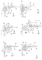
- Fig. 4 bis 6
- schematisch in einem Ausschnitt einen Teilbereich der Schutzvorrichtung nach den
Fig. 1 bis 3 in unterschiedlichen Funktionsstellungen, - Fig. 7
- in perspektivischer Darstellung die Schutzvorrichtung nach
Fig. 6 , - Fig. 8
- die Funktionsstellung gemäß
Fig. 7 unter Weglassung von Teilen der Schutzvorrichtung, - Fig. 9 bis 14
- die Schutzvorrichtung nach den
Fig. 1 bis 8 in verschiedenen Funktionsstellungen innerhalb des Laderaumes, - Fig. 15
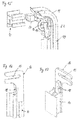
- in vergrößerter, perspektivischer Explosionsdarstellung einen Teilbereich der Schutzvorrichtung nach den
Fig. 1 bis 14 , - Fig. 16
- in perspektivischer Darstellung einen stirnseitigen Teilbereich eines Kassettengehäuses der Schutzvorrichtung nach den
Fig. 1 bis 15 und - Fig. 17
- den Teilbereich gemäß
Fig. 16 in anderer perspektivischer Darstellung. - Ein Personenkraftwagen weist gemäß den
Fig. 1 bis 3 einen Fahrzeuginnenraum 1 auf, der in einem Heckbereich einen Laderaum 2 umfasst. Der Laderaum 2 ist an seinen gegenüberliegenden Längsseiten durch jeweils eine Seitenwandung 3 des Fahrzeuginnenraumes begrenzt. Nach hinten ist der Laderaum 2 in nicht näher dargestellter Weise durch eine Heckklappe oder eine Hecktür begrenzt. Nach vorne ist der Laderaum 2 bis auf Höhe einer Fahrzeugbrüstung durch eine Rückenlehnenanordnung 5 einer Fondsitzbank begrenzt. Der Laderaum 2 weist einen Laderaumboden 4 auf, der unmittelbar hinter der Rückenlehnenanordnung 5 mit einer Vertiefung 7 versehen ist, die durch einen nicht dargestellten Deckel verschließbar sein kann. Die Vertiefung 7 ist derart gestaltet, dass ein als Aufnahmestruktur dienendes Kassettengehäuse 6 einer Schutzvorrichtung für den Laderaum 2 in die Vertiefung 7 hinein abgesenkt werden kann. Vorzugsweise schließt in abgesenkter Ruheposition eine Oberseite des Kassettengehäuses 6 bündig mit einer Oberseite des Laderaumbodens 4 ab, wobei das Kassettengehäuse 6 gleichzeitig in dieser Ruheposition die Vertiefung 7 zumindest weitgehend vollständig ausfüllt. Aufgrund der schematischen Darstellung gemäßFig. 1 ist dies aus der Zeichnung nicht klar erkennbar. - Das Kassettengehäuse 6 erstreckt sich in Fahrzeugquerrichtung und damit in Querrichtung des Laderaumes 2. Das Kassettengehäuse 6 ist in Hochrichtung des Laderaumes sowie gemäß den
Fig. 1 und 3 mit geringfügiger zusätzlicher Komponente in Längsrichtung des Laderaumes zwischen der unteren Ruheposition gemäßFig. 1 und einer oberen Funktionsposition verlagerbar, wie nachfolgend näher beschrieben wird. In dem Kassettengehäuse 6 ist eine Wickelwelle 8 drehbar gelagert. Auf der Wickelwelle 8 ist ein flexibles Flächengebilde F in Form einer Abdeckplane auf- und abwickelbar gehalten. Das Flächengebilde F ist in der Funktionsposition des Kassettengehäuses 6 aus einem nicht näher bezeichneten Längsschlitz des Kassettengehäuses 6 in Längsrichtung des Laderaumes 2 nach hinten zu dem Heckbereich etwa horizontal ausziehbar, um den Laderaum 2 zu überdecken und so einen Blick von außen auf den Laderaum 2 zu versperren. Der Wickelwelle 8 ist eine als Rückholfeder dienende Wickelfeder zugeordnet, die auf die Wickelwelle 8 ein permanentes Drehmoment in Aufwickelrichtung ausübt. Das Flächengebilde F weist an seinem in Auszugrichtung vorderen Stirnendbereich ein formstabiles Auszugprofil 9 auf, das sich über die gesamte Breite des Flächengebildes F erstreckt und an seinen gegenüberliegenden Stirnseiten in jeweils eine Führungsspur 10 bis 12 im Bereich der jeweiligen Seitenwandung 3 des Laderaumes 2 hineinragt. - Anhand der
Fig. 1 bis 14 ist erkennbar, dass die Führungsspur im Bereich von jeder der beiden gegenüberliegenden Seitenwandungen 3 einen im Wesentlichen in Hochrichtung des Laderaumes 2 erstreckten Verlagerungsabschnitt 10, einen an den Verlagerungsabschnitt 10 oben anschließenden Umlenkbereich 11 sowie einen an den Umlenkbereich 11 in Längsrichtung des Laderaumes 2 zu dem Heckbereich hin anschließenden Führungsabschnitt 12 aufweist. Der Verlagerungsabschnitt 10, der Umlenkabschnitt 11 und der Führungsabschnitt 12 gehen fluchtend ineinander über, wobei der Umlenkabschnitt kreisbogenförmig oder kreisbogenartig gestaltet ist. Der Führungsabschnitt 12 der jeweiligen Führungsspur erstreckt sich etwa horizontal in Längsrichtung des Laderaumes zu dem Heckbereich hin nach hinten. Die durch die Abschnitte gebildete Führungsspur im Bereich jeder Seitenwandung 3 des Laderaumes 2 ist an entsprechenden Abschnitten der Karosserietragstruktur des Personenkraftwagens befestigt und so stationär im Laderaum 2 angeordnet. Die jeweilige Führungsspur im Bereich der gegenüberliegenden Seitenwandungen 3 wird jeweils gebildet durch eine Profilschienenanordnung aus Metall, vorzugsweise einer Leichtmetalllegierung, deren Gestaltung anhand derFig. 7 und 8 sowie 15 bis 17 erkennbar ist. Die jeweilige Profilschienenanordnung ist vorteilhaft - in nicht näher dargestellter Weise - hinter einer entsprechenden Seitenverkleidung der jeweiligen Seitenwandung 3 angeordnet, so dass entsprechende Funktionsteile der Schutzvorrichtung, soweit sie die Führung des Kassettengehäuses 6 oder die Führung des Auszugprofils 9 betreffen, im Wesentlichen durch die entsprechende Seitenverkleidung verdeckt sind. - Das Auszugprofil 9 ragt an seinen gegenüberliegenden Stirnseiten in die jeweilige Führungsspur 10 bis 12 der gegenüberliegenden Seitenwandungen 3 hinein, um in den beiden Führungsspuren längs der Führungsspuren parallel verlagert werden zu können. Zur synchronisierten Verlagerung der beiden gegenüberliegenden Stirnseiten des Auszugprofils 9 ist in jeder Führungsspur 10 bis 12 jeweils ein Mitnehmer 14 angeordnet, der linearbeweglich in der jeweiligen Führungsspur 10 bis 12 verfahrbar ist. Der jeweilige Mitnehmer 14 nimmt das entsprechende Stirnende des Auszugprofils 9 formschlüssig auf. Jeder Mitnehmer 14 ist jedoch derart gestaltet, dass das Auszugprofil 9 bei einer starken Belastung, die insbesondere durch ein im Laderaum befindliches Hindernis bei einer Verfahrbewegung des Auszugprofils 9 auftreten kann, von den Mitnehmern 14 gelöst werden kann. Hierdurch wird vermieden, dass übermäßige Kräfte, die auf das Auszugprofil 9 wirken können, zu einer Beschädigung des Auszugprofils 9 oder der Führungsspuren 10 bis 12 führen können.
- Die beiden Mitnehmer 14 sind mithilfe jeweils eines Antriebskabels A in der jeweiligen Führungsspur längsverlagerbar. Das jeweilige Antriebskabel A ist anhand der
Fig. 9 und 12, 13 schematisch dargestellt. Die beiden Antriebskabel A sind als flexible Gewindewellen ausgeführt, die auch als Flexwellen bezeichnet werden. Die beiden Antriebskabel A sind Teil eines Antriebssystems, das einen elektrischen Antriebsmotor umfasst, der über ein entsprechendes Schneckengetriebe die Antriebskabel A synchron zueinander antreibt. Die Antriebskabel A sind zug- und drucksteif ausgeführt und flexibel gestaltet, so dass sie durch den Umlenkbereich 11 jeder Führungsspur 10 bis 12 hindurch gekrümmt verlaufen können. - Im Bereich der gegenüberliegenden Stirnseiten des Kassettengehäuses 6 ist am Kassettengehäuse 6 jeweils ein Führungsschlitten 16 befestigt, der parallel zu dem Verlagerungsabschnitt 10 der Führungsspur 10, 11, 12 in Hochrichtung des Laderaumes 2 in einem entsprechenden Schienenabschnitt der Profilschienenanordnung gleitbeweglich geführt ist (
Fig. 16 und 17 ). Der jeweilige Führungsschlitten 16 bildet jeweils ein Seitenteil des Kassettengehäuses 6 und ist fest mit dem Kassettengehäuse 6 verbunden. Der Führungsschlitten 16 weist auf Höhe des Längsschlitzes des Kassettengehäuses 6 eine Fangkulisse 13 auf, die dazu vorgesehen ist, das zugeordnete Stirnende des Auszugprofils 9 aufzunehmen. In der Funktionsposition des Kassettengehäuses 6, in der das Flächengebilde F etwa horizontal in Längsrichtung des Laderaumes nach hinten ausziehbar ist, ist die schlitzartige Fangkulisse 13 jedes Führungsschlittens 16 des Kassettengehäuses 6 fluchtend zu dem Führungsabschnitt 12 der Führungsspur 10 bis 12 jeder Seitenwandung 3 ausgerichtet. - Das Auszugprofil 9 kann daher, wenn das Flächengebilde F auf die Wickelwelle 8 innerhalb des Kassettengehäuses 6 aufgewickelt wird, in den Längsschlitz des Kassettengehäuses 6 und damit auch in die beiden zum Heckbereich hin nach hinten offenen Fangkulissen 13 der als Seitenteile für das Kassettengehäuse 6 dienenden Führungsschlitten 16 hineintauchen.
- Das Kassettengehäuse 6 wird in seiner Funktionsposition gemäß den
Fig. 2 und 3 durch zwei Verriegelungseinrichtungen gesichert, die Teil von zwei Kopplungseinrichtungen 15 sind. Jede Kopplungseinrichtung 15 ist auf Höhe des Umlenkabschnittes 11 der jeweiligen Führungsspur 10 bis 12 positioniert. Zu der jeweiligen Kopplungseinrichtung 15 zählt auch die jeweilige Fangkulisse 13 des Kassettengehäuses 6. Die beiden gegenüberliegenden Kopplungseinrichtungen wie auch die beiden gegenüberliegenden Verriegelungseinrichtungen sind identisch zueinander gestaltet. Die beiden Verriegelungseinrichtungen werden über entsprechende mechanische Steuereinrichtungen 19, 21, 22 der jeweiligen Kopplungseinrichtungen 15 synchron aus einer Verriegelungsstellung in eine Lösestellung überführt. Die beiden Verriegelungseinrichtungen dienen dazu, das Kassettengehäuse 6 in der Funktionsposition gemäß denFig. 2 und 3 zu sichern. Im Bereich der die Seitenteile des Kassettengehäuses 6 bildenden Führungsschlitten 16 ist jeweils eine keilförmige Verriegelungsaufnahme 18 vorgesehen, in die jeweils eine Sperrklinke 17 der Verriegelungseinrichtung einrastet. Die Sperrklinke 17 ist, wie anhand derFig. 9 bis 15 erkennbar ist, schwenkbeweglich gelagert zwischen einer in die Verriegelungsaufnahme 18 eingreifenden Verriegelungsstellung und einer die Verriegelungsaufnahme 18 freigebenden Freigabestellung (sieheFig. 11 und 12 ). Die entsprechende Sperrklinke 17 ist in Richtung ihrer Verriegelungsstellung federbelastet durch eine Rückstellfeder, die nicht näher dargestellt ist. - Sobald die Sperrklinken in ihre Lösestellung überführt sind, kann das Kassettengehäuse 6 mit seinen beiden Seitenteilen in Form der Führungsschlitten 16 parallel zu dem Verlagerungsabschnitt 10 für den jeweiligen Mitnehmer 14 in einen entsprechenden Schienenabschnitt der Profilschienenanordnung in Hochrichtung des Laderaumes verschoben werden. Durch die gegenüberliegenden Führungsschlitten 16 ist gewährleistet, dass das Kassettengehäuse 6 in Hochrichtung parallel verlagert wird.
- Mithilfe einer nachfolgend näher beschriebenen Zwangssteuerung wird das Kassettengehäuse 6 in Hochrichtung des Laderaumes ausschließlich in Abhängigkeit von entsprechenden Bewegungen der gegenüberliegenden Mitnehmer 14 im Bereich der Umlenkabschnitte 11 und der Verlagerungsabschnitte 10 bewegt. Hierzu weist die Kopplungseinrichtung 15 im Bereich jedes Umlenkabschnittes 11 die mechanische Steuereinrichtung auf, die eine Bewegung des jeweiligen Mitnehmers 14 zwangsläufig mit einer entsprechenden Öffnungsbewegung der jeweiligen Sperrklinke 17 koordiniert. Hierzu weist die Steuereinrichtung eine Kurbelscheibe 19 auf, die einen Steuernocken 21 aufweist, der radial von der Kurbelscheibe abragt und in die Bewegungsbahn des Mitnehmers 14 oder des Auszugprofils 9 hineinragt. Der Kurbelscheibe 19 ist zudem ein axial abragender Kurbelzapfen 22 - bezogen auf eine Drehachse der Kurbelscheibe 19 - zugeordnet, der mit einem Hebelabschnitt der Sperrklinke 17 in Kontakt ist. Sobald der Mitnehmer 14 mit dem Auszugprofil 9 in dem Führungsabschnitt 12 in Längsrichtung des Laderaumes nach vorne verschoben wird (siehe
Fig. 9 und 10 ), taucht zwangsläufig kurz vor Erreichen der aufgewickelten Ruhestellung des Flächengebildes F das Auszugprofil 9 mit seinen gegenüberliegenden Stirnenden in die Fangkulissen 13 der Führungsschlitten 16 ein. Beim weiteren Hineinverlagern des Auszugprofils 9 in die Fangkulissen 13 hinein - bei entsprechender Weiterbewegung der Mitnehmer 14 in die Umlenkabschnitte 11 - wird der Steuernocken gemäß den Darstellungen nach denFig. 9 bis 15 im Uhrzeigersinn verdreht, wodurch der Kurbelzapfen 22 zwangsläufig die Sperrklinke 17 in die Öffnungsstellung überführt. Dadurch kommt das Kassettengehäuse 6 aus der Verriegelungsstellung frei und kann in der entsprechenden Führungsbahn, die parallel zu dem Verlagerungsabschnitt 10 jeder Führungsspur nach unten verläuft, abgesenkt werden. Dadurch, dass das Auszugprofil 9 mit seinen gegenüberliegenden Stirnenden weiterhin in dem jeweiligen Mitnehmer 14 und in der Führungsspur gefangen ist und sich darüber hinaus die Fangkulissen 13 der Führungsschlitten 16 mit der Führungsspur im Bereich des Umlenkabschnittes 11 und des Verlagerungsabschnittes 10 kreuzen, ist das Auszugprofil 9 in dem Kassettengehäuse 6, genauer gesagt im Endbereich der jeweiligen Fangkulisse 13, gefangen. Dadurch stützt das Auszugprofil 9 das Kassettengehäuse 6 zwangsläufig im Bereich der Mitnehmer 14 ab, so dass das Kassettengehäuse 6 zwangsgeführt gemeinsam mit den Mitnehmern 14 nach unten abgesenkt oder auch in entgegengesetzter Richtung (sieheFig. 13 und 14 ) wieder angehoben wird. Da sich bei einem erneuten Verlagern des Auszugprofils 9 aus dem Verlagerungsabschnitt 10 nach oben in den Umlenkabschnitt 11 hinein und in Richtung des Führungsabschnittes 12 zwangsläufig die Kurbelscheibe 19 über den Steuernocken 21 wieder in die Ausgangslage zurückstellt, kann die entsprechende Rückstellfeder die jeweilige Sperrklinke 17 ebenfalls wieder in die Verriegelungsstellung zurückstellen, wodurch die Führungsschlitten 16 wieder in der Funktionsposition des Kassettengehäuses 6 formschlüssig gesichert werden. Nun kann das Auszugprofil 9 über die Mitnehmer 14 wieder in einfacher Weise aus dem Kassettengehäuse 6 und aus den Fangkulissen 13 in Richtung des Heckbereichs nach hinten herausbewegt werden. Die Ausgangslage gemäß denFig. 4 und9 ist so wiederhergestellt.
Claims (12)
- Schutzvorrichtung für einen Laderaum eines Kraftfahrzeugs mit einer formstabilen Aufnahmestruktur (6), in der eine Wickelwelle (8) drehbar gelagert ist, auf der ein flexibles Flächengebilde (F) auf- und abwickelbar gehalten ist, das an einem in Abwickelrichtung vorderen Stirnendbereich mit einem formstabilen Auszugprofil (9) versehen ist, das an seinen gegenüberliegenden Stirnseiten mit jeweils einem Mitnehmer (14) verbunden ist, der in einem in Längsrichtung des Laderaumes (2) erstreckten Führungsabschnitt (12) einer laderaumfesten Führungsspur (10 bis 12) linearbeweglich geführt ist, dadurch gekennzeichnet, dass die Aufnahmestruktur (6) in Hochrichtung des Laderaumes (2) verlagerbar ist, und dass jede Führungsspur (10 bis 12) einen Umlenkbereich (11) sowie einen in Hochrichtung des Laderaumes (2) erstreckten Verlagerungsabschnitt (10) aufweist, entlang derer der Mitnehmer (14) umlenkbar und in Hochrichtung verfahrbar ist, und dass die Aufnahmestruktur (6) eine Kopplungseinrichtung aufweist, mittels der die Aufnahmestruktur (6) abhängig von einer Position des Mitnehmers (14) gemeinsam mit dem Mitnehmer (14) höhenverlagerbar ist.
- Schutzvorrichtung nach Anspruch 1, dadurch gekennzeichnet, dass die Kopplungseinrichtung eine Fangkulisse (13) für das Auszugprofil (9) aufweist, in die das Auszugprofil (9) eintaucht abhängig von der Position des Mitnehmers (14).
- Schutzvorrichtung nach Anspruch 1 oder 2, dadurch gekennzeichnet, dass die Kopplungseinrichtung eine Verriegelungseinrichtung aufweist, die die Aufnahmestruktur (6) in einer Funktionsstellung sichert.
- Schutzvorrichtung nach Anspruch 3, dadurch gekennzeichnet, dass der Verriegelungseinrichtung eine mechanische Steuereinrichtung zugeordnet ist, die mit einer Bewegungsbahn des Mitnehmers (14) derart gekoppelt ist, dass die Verriegelungseinrichtung lösbar ist abhängig von einer Bewegung des Mitnehmers (14) in einem Bereich, in dem das Flächengebilde (F) zumindest weitgehend vollständig auf die Wickelwelle (8) aufgewickelt ist.
- Schutzvorrichtung nach einem der vorhergehenden Ansprüche, dadurch gekennzeichnet, dass die Fangkulisse (13) in Längsrichtung des Laderaumes (2) von der Wickelwelle (8) weg offen ist und zumindest weitgehend parallel zu dem Führungsabschnitt (12) für den Mitnehmer (14) ausgerichtet ist.
- Schutzvorrichtung nach Anspruch 5, dadurch gekennzeichnet, dass die Fangkulisse in der Aufnahmestruktur integriert ist.
- Schutzvorrichtung nach Anspruch 4, dadurch gekennzeichnet, dass die Steuereinrichtung ein Kurbelgetriebe aufweist, das mit einer Sperrklinke (17) der Verriegelungseinrichtung zusammenwirkt, wobei die Sperrklinke (17) die Aufnahmestruktur (6) in der Funktionsstellung formschlüssig sichert.
- Schutzvorrichtung nach einem der vorhergehenden Ansprüche, dadurch gekennzeichnet, dass die Aufnahmestruktur (6) auf jeder Stirnseite in einer laderaumfesten Führungsbahn höhenverlagerbar geführt ist, die parallel zu dem Verlagerungsabschnitt (10) für den jeweiligen Mitnehmer (14) verläuft.
- Schutzvorrichtung nach einem der vorhergehenden Ansprüche, dadurch gekennzeichnet, dass jeder Mitnehmer (14) für eine lösbare Mitnahme der Stirnseite des Auszugprofils (9) ausgestaltet ist.
- Schutzvorrichtung nach einem der vorhergehenden Ansprüche, dadurch gekennzeichnet, dass ein Antriebssystem vorgesehen ist, das für jeden Mitnehmer (14) ein flexibles Antriebskabel (A) aufweist, um die Mitnehmer (14) synchron zueinander in Längsrichtung und in Hochrichtung der jeweiligen Führungsspur (10 bis 12) zu verlagern.
- Schutzvorrichtung nach einem oder mehreren der vorhergehenden Ansprüche, dadurch gekennzeichnet, dass die Fangkulisse (13) und der in Hochrichtung erstreckte Verlagerungsabschnitt (10) der Führungsspur (10 bis 12) einander kreuzen.
- Schutzvorrichtung nach Anspruch 8, dadurch gekennzeichnet, dass die Führungsbahn für die Stirnseite der Aufnahmestruktur (6) und der Verlagerungsabschnitt 10 für den Mitnehmer (14) in einer gemeinsamen Profilschienenanordnung integriert sind.
Applications Claiming Priority (1)
| Application Number | Priority Date | Filing Date | Title |
|---|---|---|---|
| DE102015220192.9A DE102015220192B3 (de) | 2015-10-16 | 2015-10-16 | Schutzvorrichtung für einen Laderaum eines Kraftfahrzeugs |
Publications (2)
| Publication Number | Publication Date |
|---|---|
| EP3156284A1 true EP3156284A1 (de) | 2017-04-19 |
| EP3156284B1 EP3156284B1 (de) | 2018-11-07 |
Family
ID=56979442
Family Applications (1)
| Application Number | Title | Priority Date | Filing Date |
|---|---|---|---|
| EP16189775.6A Active EP3156284B1 (de) | 2015-10-16 | 2016-09-20 | Schutzvorrichtung für einen laderaum eines kraftfahrzeugs |
Country Status (6)
| Country | Link |
|---|---|
| US (1) | US10173597B2 (de) |
| EP (1) | EP3156284B1 (de) |
| JP (1) | JP2017074942A (de) |
| KR (1) | KR20170045133A (de) |
| CN (1) | CN106585502B (de) |
| DE (1) | DE102015220192B3 (de) |
Cited By (1)
| Publication number | Priority date | Publication date | Assignee | Title |
|---|---|---|---|---|
| US10173597B2 (en) * | 2015-10-16 | 2019-01-08 | Bos Gmbh & Co. Kg | Protection device for a luggage compartment of an automotive vehicle |
Families Citing this family (8)
| Publication number | Priority date | Publication date | Assignee | Title |
|---|---|---|---|---|
| DE102017109524A1 (de) * | 2017-05-04 | 2018-11-08 | Dr. Ing. H.C. F. Porsche Aktiengesellschaft | Laderaumanordnung für ein Kraftfahrzeug |
| FR3077788B1 (fr) * | 2018-02-12 | 2020-03-13 | Treves Products, Services & Innovation | Systeme de recouvrement d'un compartiment a bagages de vehicule automobile |
| CN108196077B (zh) * | 2018-02-23 | 2024-11-08 | 迈克医疗电子有限公司 | 试剂容器运载装置及运载系统 |
| KR102542953B1 (ko) * | 2018-04-12 | 2023-06-13 | 현대자동차주식회사 | 차량의 러기지룸 스크린 장치 |
| DE102018132163A1 (de) * | 2018-12-13 | 2020-06-18 | Bayerische Motoren Werke Aktiengesellschaft | Ablagevorrichtung und Fahrzeug |
| EP3725592B1 (de) * | 2019-04-17 | 2021-10-20 | Ningbo Geely Automobile Research & Development Co., Ltd. | Faltbares fahrzeugkäfigsystem |
| DE102020101952B4 (de) * | 2020-01-28 | 2025-06-18 | Bayerische Motoren Werke Aktiengesellschaft | Verfahren zum Bereitstellen eines Einklemmschutzes für ein Kraftfahrzeug |
| DE102025110742A1 (de) * | 2025-03-20 | 2026-03-19 | Audi Aktiengesellschaft | Verfahren zum Steuern von mindestens einem Kofferraumelement eines Fahrzeugs und Fahrzeuganordnung |
Citations (5)
| Publication number | Priority date | Publication date | Assignee | Title |
|---|---|---|---|---|
| EP1084907B1 (de) | 1999-09-20 | 2003-10-15 | BOS GmbH & Co. KG | Schutzvorrichtung für einen Innenraum eines Kraftfahrzeuges |
| DE10218839A1 (de) * | 2002-04-23 | 2003-11-13 | Bos Gmbh | Schutzvorrichtung für einen Laderaum eines Kraftfahrzeugs |
| DE10357153A1 (de) * | 2003-12-06 | 2005-07-14 | Bayerische Motoren Werke Ag | In Gebrauchsstellung und Verstauungsstellung am Fahrzeug anordenbare Gepäckraumteilungsvorrichtung |
| DE102009010967A1 (de) * | 2009-02-27 | 2010-09-02 | Bayerische Motoren Werke Aktiengesellschaft | Kraftfahrzeug |
| DE102014211163A1 (de) | 2013-06-28 | 2014-12-31 | Bos Gmbh & Co. Kg | Schutzvorrichtung für einen Laderaum eines Kraftfahrzeugs sowie Antriebsvorrichtung hierfür |
Family Cites Families (37)
| Publication number | Priority date | Publication date | Assignee | Title |
|---|---|---|---|---|
| US1950927A (en) * | 1930-07-08 | 1934-03-13 | Mcmillan William | Flexible cover for vehicles |
| FR2431395A1 (fr) * | 1978-07-21 | 1980-02-15 | Citroen Sa | Vehicule a plage arriere amovible |
| US5011208A (en) * | 1990-02-23 | 1991-04-30 | General Motors Corporation | Concealed integrated seat cargo screen |
| US5083831A (en) * | 1990-07-09 | 1992-01-28 | Foyen John R | Carpet protection device |
| JP3249775B2 (ja) * | 1998-03-02 | 2002-01-21 | 河西工業株式会社 | 自動車用トノカバー装置 |
| DE19906648B4 (de) * | 1999-02-18 | 2014-04-17 | Bayerische Motoren Werke Aktiengesellschaft | Vorrichtung zur Führung eines Ladebodens in einem Gepäckraum eines Personenkraftfahrzeugs |
| DE10140256B4 (de) * | 2001-08-07 | 2012-09-06 | Bos Gmbh & Co. Kg | Schutzvorrichtung für einen Laderaum eines Fahrzeugs |
| EP1332919B1 (de) * | 2002-01-31 | 2007-10-31 | BOS GmbH & Co. KG | Aufnahmevorrichtung für einen Laderaum eines Kraftfahrzeugs |
| FR2844485B1 (fr) * | 2002-09-18 | 2004-12-24 | Wagon Automotive Snc | Dispositif cache-bagages pour vehicule automobile a hayon arriere, a commande automatique, et vehicule automobile correspondant. |
| DE10331421A1 (de) * | 2003-07-10 | 2005-02-17 | Webasto Ag | Kraftfahrzeug mit verbesserter Heckfunktionalität |
| DE102004060747B4 (de) * | 2004-12-15 | 2010-09-16 | Webasto Ag | Fahrzeug mit einer auf- und abrollbar gelagerten Laderaum-Abdeckung |
| DE602006005885D1 (de) * | 2005-11-22 | 2009-05-07 | Mazda Motor | Hintere Struktur eines Kraftfahrzeugs |
| US7673921B2 (en) * | 2007-01-24 | 2010-03-09 | Mazda Motor Corporation | Tonneau cover device of vehicle |
| DE102007021428B4 (de) * | 2007-05-03 | 2012-08-30 | Bos Gmbh & Co. Kg | Abdeckungssystem für einen Heckstauraum eines Fahrzeugs |
| US7891729B2 (en) * | 2007-10-15 | 2011-02-22 | Kanto Auto Works, Ltd. | Sliding roof structure and vehicle equipped with the same |
| DE102007057073B4 (de) * | 2007-11-23 | 2011-12-29 | Bos Gmbh & Co. Kg | Abdecksystem für ein Fahrzeug |
| DE102007058255B3 (de) * | 2007-11-26 | 2009-07-02 | Bos Gmbh & Co. Kg | Staufach mit Tragrahmen und Aufnahmevorrichtung für einen Tragrahmen |
| FR2931411B1 (fr) * | 2008-05-20 | 2010-06-18 | Magna Steyr France Sas | Agencement d'un coffre de vehicule automobile et vehicule automobile comportant un tel agencement |
| WO2010079576A1 (ja) * | 2009-01-09 | 2010-07-15 | 本田技研工業株式会社 | 巻取り式トノカバー・アセンブリを収納するための荷室構造 |
| DE102010015182B4 (de) * | 2010-04-13 | 2013-08-08 | Bos Gmbh & Co. Kg | Schutzvorrichtung für einen Fahrzeuginnenraum |
| FR2992599B1 (fr) * | 2012-06-27 | 2014-08-22 | Renault Sa | Vehicule a compartiment a bagages dote d'un tendelet escamotable motorise |
| US8727414B2 (en) * | 2012-07-11 | 2014-05-20 | Honda Motor Co., Ltd. | Stowable cargo cover |
| DE102012013753A1 (de) * | 2012-07-12 | 2014-05-15 | GM Global Technology Operations LLC (n. d. Ges. d. Staates Delaware) | Kraftfahrzeug mit Höhenverstellvorrichtungfür Ladeboden |
| FR2995571A3 (fr) * | 2012-09-20 | 2014-03-21 | Renault Sa | Ensemble d'occultation reglable verticalement pour coffre arriere de vehicule automobile |
| DE102012221585B4 (de) * | 2012-11-26 | 2016-11-24 | Bos Gmbh & Co. Kg | Rückhaltevorrichtung für einen Fahrzeuginnenraum |
| DE102013009943A1 (de) * | 2013-06-13 | 2014-06-26 | Audi Ag | Abdeckvorrichtung für ein Fahrzeug mit einer im Bereich eines Laderaums des Fahrzeugs vorgesehenen Kofferraumschutzmatte |
| WO2015067301A1 (fr) * | 2013-11-05 | 2015-05-14 | Renault S.A.S. | Agencement d'un coffre pour vehicule equipe d'un tendelet escamotable |
| GB2522417B (en) * | 2014-01-22 | 2016-09-14 | Ford Global Tech Llc | Roll cover assembly |
| GB2527053B (en) * | 2014-06-10 | 2018-02-28 | Jaguar Land Rover Ltd | Load space covering device |
| EP3075601B1 (de) * | 2015-03-30 | 2017-07-12 | Toyota Boshoku Kabushiki Kaisha | Layoutsystem für laderaum eines fahrzeugs |
| DE102015208627B3 (de) * | 2015-05-08 | 2016-07-07 | Bos Gmbh & Co. Kg | Schutzvorrichtung für einen Fahrzeuginnenraum |
| DE102015110891B4 (de) * | 2015-07-06 | 2026-02-19 | Bayerische Motoren Werke Aktiengesellschaft | Abtrennvorrichtung für einen Laderaum eines Kraftfahrzeugs |
| EP3138737B1 (de) * | 2015-09-07 | 2018-01-31 | Volvo Car Corporation | Leichte kostengünstige spannende frachtabdeckung |
| EP3150439B1 (de) * | 2015-10-01 | 2018-12-12 | FKT GmbH | Abtrennvorrichtung für einen laderaum eines kraftfahrzeugs, kanalbauteil einer antriebsvorrichtung in einem kraftfahrzeug sowie kraftfahrzeug |
| DE102015220192B3 (de) * | 2015-10-16 | 2017-03-09 | Bos Gmbh & Co. Kg | Schutzvorrichtung für einen Laderaum eines Kraftfahrzeugs |
| FR3046970A3 (fr) * | 2016-01-25 | 2017-07-28 | Renault Sas | Dispositif de separation verticale entre une rangee de sieges et une zone de chargement d'un vehicule automobile |
| WO2017145310A1 (ja) * | 2016-02-25 | 2017-08-31 | 河西工業株式会社 | トノカバー装置 |
-
2015
- 2015-10-16 DE DE102015220192.9A patent/DE102015220192B3/de not_active Expired - Fee Related
-
2016
- 2016-09-20 EP EP16189775.6A patent/EP3156284B1/de active Active
- 2016-10-04 US US15/284,597 patent/US10173597B2/en not_active Expired - Fee Related
- 2016-10-14 JP JP2016202614A patent/JP2017074942A/ja active Pending
- 2016-10-14 KR KR1020160133661A patent/KR20170045133A/ko not_active Withdrawn
- 2016-10-17 CN CN201610903702.XA patent/CN106585502B/zh active Active
Patent Citations (5)
| Publication number | Priority date | Publication date | Assignee | Title |
|---|---|---|---|---|
| EP1084907B1 (de) | 1999-09-20 | 2003-10-15 | BOS GmbH & Co. KG | Schutzvorrichtung für einen Innenraum eines Kraftfahrzeuges |
| DE10218839A1 (de) * | 2002-04-23 | 2003-11-13 | Bos Gmbh | Schutzvorrichtung für einen Laderaum eines Kraftfahrzeugs |
| DE10357153A1 (de) * | 2003-12-06 | 2005-07-14 | Bayerische Motoren Werke Ag | In Gebrauchsstellung und Verstauungsstellung am Fahrzeug anordenbare Gepäckraumteilungsvorrichtung |
| DE102009010967A1 (de) * | 2009-02-27 | 2010-09-02 | Bayerische Motoren Werke Aktiengesellschaft | Kraftfahrzeug |
| DE102014211163A1 (de) | 2013-06-28 | 2014-12-31 | Bos Gmbh & Co. Kg | Schutzvorrichtung für einen Laderaum eines Kraftfahrzeugs sowie Antriebsvorrichtung hierfür |
Cited By (1)
| Publication number | Priority date | Publication date | Assignee | Title |
|---|---|---|---|---|
| US10173597B2 (en) * | 2015-10-16 | 2019-01-08 | Bos Gmbh & Co. Kg | Protection device for a luggage compartment of an automotive vehicle |
Also Published As
| Publication number | Publication date |
|---|---|
| DE102015220192B3 (de) | 2017-03-09 |
| CN106585502B (zh) | 2020-11-03 |
| US10173597B2 (en) | 2019-01-08 |
| US20170106802A1 (en) | 2017-04-20 |
| KR20170045133A (ko) | 2017-04-26 |
| EP3156284B1 (de) | 2018-11-07 |
| JP2017074942A (ja) | 2017-04-20 |
| CN106585502A (zh) | 2017-04-26 |
Similar Documents
| Publication | Publication Date | Title |
|---|---|---|
| EP3156284B1 (de) | Schutzvorrichtung für einen laderaum eines kraftfahrzeugs | |
| DE102009058293B4 (de) | Schutzvorrichtung für einen Fahrzeuginnenraum | |
| DE10324289A1 (de) | Schutzvorrichtung für einen Innenraum eines Kraftfahrzeugs | |
| EP3231649B1 (de) | Beschattungssystem für ein kraftfahrzeug | |
| DE102015225811A1 (de) | Dachsystem für ein Kraftfahrzeug | |
| DE102019203161A1 (de) | Ladebodenanordnung für einen Laderaum eines Kraftfahrzeugs | |
| DE102009036606B3 (de) | Schutzvorrichtung für einen Fahrzeuginnenraum | |
| DE102005055625C5 (de) | Laderaumabdeckung für ein Fahrzeug | |
| EP2062781A1 (de) | Abdecksystem für ein Fahrzeug | |
| WO2014090759A1 (de) | Schutzvorrichtung, insbesondere beschattungsvorrichtung, für einen fahrzeuginnenraum eines kraftfahrzeugs | |
| DE102005005769A1 (de) | Heckklappe eines Fahrzeugs | |
| EP3090901A1 (de) | Schutzvorrichtung für einen fahrzeuginnenraum | |
| DE102015110891A1 (de) | Abtrennvorrichtung für einen Laderaum eines Kraftfahrzeugs | |
| DE10320108B4 (de) | Kraftfahrzeug mit einer Abschottungseinrichtung | |
| DE102019218122B4 (de) | Beschattungsvorrichtung für eine Seitenscheibe eines Kraftfahrzeugs | |
| EP1775165A1 (de) | Abdeckvorrichtung für einen Laderaum eines Kraftfahrzeugs | |
| DE102010025213B4 (de) | Schutzvorrichtung für einen Fahrzeuginnenraum | |
| DE102016219504A1 (de) | Laderaumabdeckvorrichtung für ein Kraftfahrzeug | |
| DE102020112528A1 (de) | Kraftfahrzeug mit einer Karosserie | |
| EP3213947B1 (de) | Beschattungsvorrichtung für einen fahrzeuginnenraum | |
| DE202013010436U1 (de) | Schutzvorrichtung für einen Fahrzeuginnenraum sowie Hubmechanik hierfür | |
| DE102012215433A1 (de) | Rollosystem für einen Fahrzeuginnenraum | |
| DE102012200928A1 (de) | Funtkionsanordnung für einen Fahrzeuginnenraum | |
| DE102017220725B4 (de) | Vorrichtung zur Halterung einer Gehäusestruktur in einem Fahrzeuginnenraum | |
| DE102016213199A1 (de) | Beschattungsvorrichtung für eine Seitenscheibe eines Kraftfahrzeugs |
Legal Events
| Date | Code | Title | Description |
|---|---|---|---|
| PUAI | Public reference made under article 153(3) epc to a published international application that has entered the european phase |
Free format text: ORIGINAL CODE: 0009012 |
|
| STAA | Information on the status of an ep patent application or granted ep patent |
Free format text: STATUS: THE APPLICATION HAS BEEN PUBLISHED |
|
| AK | Designated contracting states |
Kind code of ref document: A1 Designated state(s): AL AT BE BG CH CY CZ DE DK EE ES FI FR GB GR HR HU IE IS IT LI LT LU LV MC MK MT NL NO PL PT RO RS SE SI SK SM TR |
|
| AX | Request for extension of the european patent |
Extension state: BA ME |
|
| STAA | Information on the status of an ep patent application or granted ep patent |
Free format text: STATUS: REQUEST FOR EXAMINATION WAS MADE |
|
| STAA | Information on the status of an ep patent application or granted ep patent |
Free format text: STATUS: EXAMINATION IS IN PROGRESS |
|
| 17P | Request for examination filed |
Effective date: 20170807 |
|
| RBV | Designated contracting states (corrected) |
Designated state(s): AL AT BE BG CH CY CZ DE DK EE ES FI FR GB GR HR HU IE IS IT LI LT LU LV MC MK MT NL NO PL PT RO RS SE SI SK SM TR |
|
| 17Q | First examination report despatched |
Effective date: 20170906 |
|
| GRAP | Despatch of communication of intention to grant a patent |
Free format text: ORIGINAL CODE: EPIDOSNIGR1 |
|
| STAA | Information on the status of an ep patent application or granted ep patent |
Free format text: STATUS: GRANT OF PATENT IS INTENDED |
|
| INTG | Intention to grant announced |
Effective date: 20180528 |
|
| GRAS | Grant fee paid |
Free format text: ORIGINAL CODE: EPIDOSNIGR3 |
|
| GRAA | (expected) grant |
Free format text: ORIGINAL CODE: 0009210 |
|
| STAA | Information on the status of an ep patent application or granted ep patent |
Free format text: STATUS: THE PATENT HAS BEEN GRANTED |
|
| AK | Designated contracting states |
Kind code of ref document: B1 Designated state(s): AL AT BE BG CH CY CZ DE DK EE ES FI FR GB GR HR HU IE IS IT LI LT LU LV MC MK MT NL NO PL PT RO RS SE SI SK SM TR |
|
| REG | Reference to a national code |
Ref country code: GB Ref legal event code: FG4D Free format text: NOT ENGLISH |
|
| REG | Reference to a national code |
Ref country code: CH Ref legal event code: EP Ref country code: AT Ref legal event code: REF Ref document number: 1061666 Country of ref document: AT Kind code of ref document: T Effective date: 20181115 |
|
| REG | Reference to a national code |
Ref country code: DE Ref legal event code: R096 Ref document number: 502016002423 Country of ref document: DE |
|
| REG | Reference to a national code |
Ref country code: IE Ref legal event code: FG4D Free format text: LANGUAGE OF EP DOCUMENT: GERMAN |
|
| REG | Reference to a national code |
Ref country code: NL Ref legal event code: MP Effective date: 20181107 |
|
| REG | Reference to a national code |
Ref country code: LT Ref legal event code: MG4D |
|
| PG25 | Lapsed in a contracting state [announced via postgrant information from national office to epo] |
Ref country code: ES Free format text: LAPSE BECAUSE OF FAILURE TO SUBMIT A TRANSLATION OF THE DESCRIPTION OR TO PAY THE FEE WITHIN THE PRESCRIBED TIME-LIMIT Effective date: 20181107 Ref country code: LV Free format text: LAPSE BECAUSE OF FAILURE TO SUBMIT A TRANSLATION OF THE DESCRIPTION OR TO PAY THE FEE WITHIN THE PRESCRIBED TIME-LIMIT Effective date: 20181107 Ref country code: FI Free format text: LAPSE BECAUSE OF FAILURE TO SUBMIT A TRANSLATION OF THE DESCRIPTION OR TO PAY THE FEE WITHIN THE PRESCRIBED TIME-LIMIT Effective date: 20181107 Ref country code: BG Free format text: LAPSE BECAUSE OF FAILURE TO SUBMIT A TRANSLATION OF THE DESCRIPTION OR TO PAY THE FEE WITHIN THE PRESCRIBED TIME-LIMIT Effective date: 20190207 Ref country code: HR Free format text: LAPSE BECAUSE OF FAILURE TO SUBMIT A TRANSLATION OF THE DESCRIPTION OR TO PAY THE FEE WITHIN THE PRESCRIBED TIME-LIMIT Effective date: 20181107 Ref country code: LT Free format text: LAPSE BECAUSE OF FAILURE TO SUBMIT A TRANSLATION OF THE DESCRIPTION OR TO PAY THE FEE WITHIN THE PRESCRIBED TIME-LIMIT Effective date: 20181107 Ref country code: NO Free format text: LAPSE BECAUSE OF FAILURE TO SUBMIT A TRANSLATION OF THE DESCRIPTION OR TO PAY THE FEE WITHIN THE PRESCRIBED TIME-LIMIT Effective date: 20190207 Ref country code: IS Free format text: LAPSE BECAUSE OF FAILURE TO SUBMIT A TRANSLATION OF THE DESCRIPTION OR TO PAY THE FEE WITHIN THE PRESCRIBED TIME-LIMIT Effective date: 20190307 |
|
| PG25 | Lapsed in a contracting state [announced via postgrant information from national office to epo] |
Ref country code: RS Free format text: LAPSE BECAUSE OF FAILURE TO SUBMIT A TRANSLATION OF THE DESCRIPTION OR TO PAY THE FEE WITHIN THE PRESCRIBED TIME-LIMIT Effective date: 20181107 Ref country code: GR Free format text: LAPSE BECAUSE OF FAILURE TO SUBMIT A TRANSLATION OF THE DESCRIPTION OR TO PAY THE FEE WITHIN THE PRESCRIBED TIME-LIMIT Effective date: 20190208 Ref country code: PT Free format text: LAPSE BECAUSE OF FAILURE TO SUBMIT A TRANSLATION OF THE DESCRIPTION OR TO PAY THE FEE WITHIN THE PRESCRIBED TIME-LIMIT Effective date: 20190307 Ref country code: NL Free format text: LAPSE BECAUSE OF FAILURE TO SUBMIT A TRANSLATION OF THE DESCRIPTION OR TO PAY THE FEE WITHIN THE PRESCRIBED TIME-LIMIT Effective date: 20181107 Ref country code: SE Free format text: LAPSE BECAUSE OF FAILURE TO SUBMIT A TRANSLATION OF THE DESCRIPTION OR TO PAY THE FEE WITHIN THE PRESCRIBED TIME-LIMIT Effective date: 20181107 Ref country code: AL Free format text: LAPSE BECAUSE OF FAILURE TO SUBMIT A TRANSLATION OF THE DESCRIPTION OR TO PAY THE FEE WITHIN THE PRESCRIBED TIME-LIMIT Effective date: 20181107 |
|
| PG25 | Lapsed in a contracting state [announced via postgrant information from national office to epo] |
Ref country code: CZ Free format text: LAPSE BECAUSE OF FAILURE TO SUBMIT A TRANSLATION OF THE DESCRIPTION OR TO PAY THE FEE WITHIN THE PRESCRIBED TIME-LIMIT Effective date: 20181107 Ref country code: IT Free format text: LAPSE BECAUSE OF FAILURE TO SUBMIT A TRANSLATION OF THE DESCRIPTION OR TO PAY THE FEE WITHIN THE PRESCRIBED TIME-LIMIT Effective date: 20181107 Ref country code: PL Free format text: LAPSE BECAUSE OF FAILURE TO SUBMIT A TRANSLATION OF THE DESCRIPTION OR TO PAY THE FEE WITHIN THE PRESCRIBED TIME-LIMIT Effective date: 20181107 Ref country code: DK Free format text: LAPSE BECAUSE OF FAILURE TO SUBMIT A TRANSLATION OF THE DESCRIPTION OR TO PAY THE FEE WITHIN THE PRESCRIBED TIME-LIMIT Effective date: 20181107 |
|
| REG | Reference to a national code |
Ref country code: DE Ref legal event code: R097 Ref document number: 502016002423 Country of ref document: DE |
|
| PG25 | Lapsed in a contracting state [announced via postgrant information from national office to epo] |
Ref country code: RO Free format text: LAPSE BECAUSE OF FAILURE TO SUBMIT A TRANSLATION OF THE DESCRIPTION OR TO PAY THE FEE WITHIN THE PRESCRIBED TIME-LIMIT Effective date: 20181107 Ref country code: SK Free format text: LAPSE BECAUSE OF FAILURE TO SUBMIT A TRANSLATION OF THE DESCRIPTION OR TO PAY THE FEE WITHIN THE PRESCRIBED TIME-LIMIT Effective date: 20181107 Ref country code: SM Free format text: LAPSE BECAUSE OF FAILURE TO SUBMIT A TRANSLATION OF THE DESCRIPTION OR TO PAY THE FEE WITHIN THE PRESCRIBED TIME-LIMIT Effective date: 20181107 Ref country code: EE Free format text: LAPSE BECAUSE OF FAILURE TO SUBMIT A TRANSLATION OF THE DESCRIPTION OR TO PAY THE FEE WITHIN THE PRESCRIBED TIME-LIMIT Effective date: 20181107 |
|
| PLBE | No opposition filed within time limit |
Free format text: ORIGINAL CODE: 0009261 |
|
| STAA | Information on the status of an ep patent application or granted ep patent |
Free format text: STATUS: NO OPPOSITION FILED WITHIN TIME LIMIT |
|
| 26N | No opposition filed |
Effective date: 20190808 |
|
| PG25 | Lapsed in a contracting state [announced via postgrant information from national office to epo] |
Ref country code: SI Free format text: LAPSE BECAUSE OF FAILURE TO SUBMIT A TRANSLATION OF THE DESCRIPTION OR TO PAY THE FEE WITHIN THE PRESCRIBED TIME-LIMIT Effective date: 20181107 |
|
| PG25 | Lapsed in a contracting state [announced via postgrant information from national office to epo] |
Ref country code: TR Free format text: LAPSE BECAUSE OF FAILURE TO SUBMIT A TRANSLATION OF THE DESCRIPTION OR TO PAY THE FEE WITHIN THE PRESCRIBED TIME-LIMIT Effective date: 20181107 |
|
| PG25 | Lapsed in a contracting state [announced via postgrant information from national office to epo] |
Ref country code: MC Free format text: LAPSE BECAUSE OF FAILURE TO SUBMIT A TRANSLATION OF THE DESCRIPTION OR TO PAY THE FEE WITHIN THE PRESCRIBED TIME-LIMIT Effective date: 20181107 |
|
| REG | Reference to a national code |
Ref country code: CH Ref legal event code: PL |
|
| PG25 | Lapsed in a contracting state [announced via postgrant information from national office to epo] |
Ref country code: CH Free format text: LAPSE BECAUSE OF NON-PAYMENT OF DUE FEES Effective date: 20190930 Ref country code: LI Free format text: LAPSE BECAUSE OF NON-PAYMENT OF DUE FEES Effective date: 20190930 Ref country code: IE Free format text: LAPSE BECAUSE OF NON-PAYMENT OF DUE FEES Effective date: 20190920 Ref country code: LU Free format text: LAPSE BECAUSE OF NON-PAYMENT OF DUE FEES Effective date: 20190920 |
|
| REG | Reference to a national code |
Ref country code: BE Ref legal event code: MM Effective date: 20190930 |
|
| PG25 | Lapsed in a contracting state [announced via postgrant information from national office to epo] |
Ref country code: BE Free format text: LAPSE BECAUSE OF NON-PAYMENT OF DUE FEES Effective date: 20190930 |
|
| PG25 | Lapsed in a contracting state [announced via postgrant information from national office to epo] |
Ref country code: FR Free format text: LAPSE BECAUSE OF NON-PAYMENT OF DUE FEES Effective date: 20190930 |
|
| GBPC | Gb: european patent ceased through non-payment of renewal fee |
Effective date: 20200920 |
|
| PG25 | Lapsed in a contracting state [announced via postgrant information from national office to epo] |
Ref country code: CY Free format text: LAPSE BECAUSE OF FAILURE TO SUBMIT A TRANSLATION OF THE DESCRIPTION OR TO PAY THE FEE WITHIN THE PRESCRIBED TIME-LIMIT Effective date: 20181107 |
|
| PG25 | Lapsed in a contracting state [announced via postgrant information from national office to epo] |
Ref country code: MT Free format text: LAPSE BECAUSE OF FAILURE TO SUBMIT A TRANSLATION OF THE DESCRIPTION OR TO PAY THE FEE WITHIN THE PRESCRIBED TIME-LIMIT Effective date: 20181107 Ref country code: HU Free format text: LAPSE BECAUSE OF FAILURE TO SUBMIT A TRANSLATION OF THE DESCRIPTION OR TO PAY THE FEE WITHIN THE PRESCRIBED TIME-LIMIT; INVALID AB INITIO Effective date: 20160920 |
|
| PG25 | Lapsed in a contracting state [announced via postgrant information from national office to epo] |
Ref country code: GB Free format text: LAPSE BECAUSE OF NON-PAYMENT OF DUE FEES Effective date: 20200920 |
|
| PG25 | Lapsed in a contracting state [announced via postgrant information from national office to epo] |
Ref country code: MK Free format text: LAPSE BECAUSE OF FAILURE TO SUBMIT A TRANSLATION OF THE DESCRIPTION OR TO PAY THE FEE WITHIN THE PRESCRIBED TIME-LIMIT Effective date: 20181107 |
|
| REG | Reference to a national code |
Ref country code: AT Ref legal event code: MM01 Ref document number: 1061666 Country of ref document: AT Kind code of ref document: T Effective date: 20210920 |
|
| PG25 | Lapsed in a contracting state [announced via postgrant information from national office to epo] |
Ref country code: AT Free format text: LAPSE BECAUSE OF NON-PAYMENT OF DUE FEES Effective date: 20210920 |
|
| PGFP | Annual fee paid to national office [announced via postgrant information from national office to epo] |
Ref country code: DE Payment date: 20250924 Year of fee payment: 10 |