EP1084907B1 - Schutzvorrichtung für einen Innenraum eines Kraftfahrzeuges - Google Patents
Schutzvorrichtung für einen Innenraum eines Kraftfahrzeuges Download PDFInfo
- Publication number
- EP1084907B1 EP1084907B1 EP00117360A EP00117360A EP1084907B1 EP 1084907 B1 EP1084907 B1 EP 1084907B1 EP 00117360 A EP00117360 A EP 00117360A EP 00117360 A EP00117360 A EP 00117360A EP 1084907 B1 EP1084907 B1 EP 1084907B1
- Authority
- EP
- European Patent Office
- Prior art keywords
- coupling member
- guide element
- protection device
- protective structure
- coupling
- Prior art date
- Legal status (The legal status is an assumption and is not a legal conclusion. Google has not performed a legal analysis and makes no representation as to the accuracy of the status listed.)
- Expired - Lifetime
Links
Images


Classifications
-
- B—PERFORMING OPERATIONS; TRANSPORTING
- B60—VEHICLES IN GENERAL
- B60R—VEHICLES, VEHICLE FITTINGS, OR VEHICLE PARTS, NOT OTHERWISE PROVIDED FOR
- B60R5/00—Compartments within vehicle body primarily intended or sufficiently spacious for trunks, suit-cases, or the like
- B60R5/04—Compartments within vehicle body primarily intended or sufficiently spacious for trunks, suit-cases, or the like arranged at rear of vehicle
-
- B—PERFORMING OPERATIONS; TRANSPORTING
- B60—VEHICLES IN GENERAL
- B60R—VEHICLES, VEHICLE FITTINGS, OR VEHICLE PARTS, NOT OTHERWISE PROVIDED FOR
- B60R5/00—Compartments within vehicle body primarily intended or sufficiently spacious for trunks, suit-cases, or the like
- B60R5/04—Compartments within vehicle body primarily intended or sufficiently spacious for trunks, suit-cases, or the like arranged at rear of vehicle
- B60R5/044—Compartments within vehicle body primarily intended or sufficiently spacious for trunks, suit-cases, or the like arranged at rear of vehicle luggage covering means, e.g. parcel shelves
- B60R5/045—Compartments within vehicle body primarily intended or sufficiently spacious for trunks, suit-cases, or the like arranged at rear of vehicle luggage covering means, e.g. parcel shelves collapsible or transformable
- B60R5/047—Compartments within vehicle body primarily intended or sufficiently spacious for trunks, suit-cases, or the like arranged at rear of vehicle luggage covering means, e.g. parcel shelves collapsible or transformable collapsible by rolling-up
Definitions
- the invention relates to a protective device for an interior of a motor vehicle with a spanned at least largely flat in a protective position
- Protective structure that between at least by means of a drive device two positions is movably mounted, at least with the protective structure a guide element is connected, which by means of at least one Coupling member can be carried with transmission means of the drive device.
- a protective device on which the invention is based can be used both as a load compartment cover, which can be moved horizontally, and also as a separating device a vertically extendable partition net or also as a sun protection roller blind for Darken at least one pane of the motor vehicle.
- a protective device in the form of a loading space cover is known from DE 198 25 353 A1 known.
- the well-known load compartment cover has a horizontally extendable Cover roller blind on that by means of an electric drive device between a rest position releasing the cargo space and one of the cargo space covering protective position is movably mounted.
- the roller blind has at its front end - in the pull-out direction - on a pull-out rod, their opposite ends laterally over the serving as a protective structure Protect the roller blind.
- These ends form guide elements that are in are each held a U-shaped, upwardly open coupling member.
- Each coupling member is on a toothed belt serving as a transmission medium attached, which extends in the direction of extension, i.e. aligned horizontally, extends.
- Each toothed belt can be actuated by means of an electric drive motor. Both Drive motors can be controlled coordinated, so that a parallel Extending or retracting the pull-out rod and thus the roller blind.
- the front ends of the pull-out rod that serve as guide elements can be adjusted can be removed from the coupling links at the top. In the same way the pull-out rod can be inserted between the coupling links from above are used, whereby the cover roller blind again with the drive device can be connected.
- DE 35 05 143 A1 describes a device for guiding a curtain on one Motor vehicle window is known in which the curtain over several fastening clips is connected to a steel wire serving as a control element. On the front end of the steel wire is fixed in a moving part, which is the entrainment the curtain is guaranteed when the steel wire moves.
- a Overload protection is by a slip clutch in the area of the drive motor intended.
- the object of the invention is to provide a protective device of the type mentioned to create a flawless and simple with simple means even in the event of accidents safe movement function of the protective structure guaranteed.
- the at least one coupling member for carrying the at least one guide element with at least one Receiving element is provided, which has a limited coupling force, at if the guide element is exceeded, it is released from the receiving element becomes.
- the solution according to the invention is suitable for protective structures, which only have a single guide element and also for protective structures, which have two or more guide elements.
- the drive device can be a single drive unit or have several drive units.
- the drive device has preferably a single, central electric drive, which by means of a synchronization a protective structure over two guide elements on opposite Leads parallel.
- the appropriate protective structure be it a separating network, Cover roller blind of a cargo hold cover or a sun protection roller blind
- the drive device Since the occurrence of a higher load than that of the drive device at least one guide element and thus the protective structure of the drive device is uncoupled, the drive device cannot be overloaded occur.
- the force-dependent coupling or decoupling at least will a guide element when the protective structure strikes an obstacle automatically and inevitably released from the coupling member while the Coupling member is moved further by the drive device.
- the guide element is automatically again recorded and taken with the movement of the coupling member.
- Uncoupling can also be done in a simple manner in that the protective structure manually in the direction of movement or against the direction of movement the drive device is moved, thereby decoupling the protective structure he follows.
- the coupling member has at least one receiving element thus only a limited clutch force in each Direction of movement of the at least one coupling member. Once this Coupling force (driving force) is exceeded, the protective structure of solved the at least one coupling member.
- the guide element and thus the protective structure with the at least one coupling member reconnected as soon as the coupling member the position of the guide element achieved with a correspondingly reversed movement. It is therefore essential that the guide element is always in the path of movement of the coupling member is guided.
- the at least one coupling member can be in horizontal, in vertical or inclined, vehicle-fixed guides be stored.
- the guides can be parallel or non-parallel to each other be aligned.
- the at least one coupling member is the same in each case Way positively guided, as this is the at least one guide element of the Protective structure is to the respective due to the same trajectory To be able to pick up the guide element again and again.
- To achieve a limited Coupling force for the at least one receiving element can do that Recording element be mechanically spring-loaded movable. It is also possible, the receiving element and the guide element of the protective structure with to provide corresponding magnetic elements. Other non-positive or positive Connections with a corresponding force limit can be used.
- each coupling member is fixed in the vehicle Guide profile mounted linearly movable, which also the corresponding guide element assigned. This ensures that the coupling member Find the guide profile, which is temporarily separated from the coupling member can, as soon as it runs over the position of the guide element again.
- this is at least one receiving element the coupling member mechanically effective and between a stop position and a release position transverse to the direction of movement of the coupling member movably supported against the force of a return spring. At least a receiving element thus forms a force-dependent locking element, the is designed simply and safely due to the mechanical function.
- two coupling members are on opposite Pages synchronized linearly, each one Take, release or pick up the guide element of the protective structure.
- This configuration is particularly suitable for the use of the protective device as a cargo space cover, in which the opposite ends of one Extraction profile, which serve as guide elements, each laterally in accordance linearly guided coupling members are held in a force-limited manner.
- each coupling member has two receiving elements on the opposite directions of movement of the coupling member are coordinated.
- the two receiving elements preferably take the respective guide element between them.
- this is a receiving element its driving force designed stronger than the other receiving element.
- the protective structure is independent in one direction of movement a tensile or compressive force is still exerted by the drive device. This is particularly the case with luggage compartment covers where the cover blind is held on a roller shaft loaded with a return spring. This will with manual pull-out ensures that the cover blind returns to its rest position withdrawn as soon as it is unlocked.
- To prevent the corresponding tensile or compressive force with the driving force of the drive device added and thus unintentionally loosening the at least one guide element caused by the receiving element is the described configuration intended.
- the at least one guide element at least one stationary stop to secure the protective structure in assigned to different positions, by means of the at least one coupling member in a release position permitting the movement of the protective structure is transferable.
- Such stationary, movable stops are also located thus in the path of movement of the at least one coupling member, so that when crossing the stops by the at least one coupling member these are inevitably transferred to the release position. This ensures that the protective structure through the stops in the respective position is held as long as it is not received by the coupling member.
- the stops are as spring-loaded, resilient locking elements designed with bevels for the respective coupling member are provided. This makes it easy to loosen the Stops can be achieved as soon as the coupling member reaches the corresponding position of the the respective stop.
- appropriate stops provided. in principle however, it is also possible to have only a single stop for the extended Protective position to be provided if the protective structure is in the rest position is held by a corresponding return spring.
- the solution according to the invention is described below on the basis of various Embodiments of a protective device in the form of a Load compartment cover for a station wagon described.
- the solution according to the invention is not based on limited to the described embodiments, but extends to other types of the invention
- Protective devices in particular separators between Load space and passenger compartment in a station wagon and sun blinds for vehicle windows.
- the cargo space cover 1 has a protective structure in the form of a tarpaulin 2, the roller shaft stored in a cassette housing is held.
- the cassette housing is generally known Positioned firmly in place of the cargo hold.
- the tarpaulin 2 At her in the direction of extension front end is the tarpaulin 2 with a designed as a contour part extract 3, the one extending across the entire width of the tarpaulin 2 Has pull rod.
- the pull-out rod protrudes with hers opposite ends laterally over the tarpaulin 2 and forms a guide element with these ends 4, positioned in the horizontal, vehicle-fixed Guide profiles 5 are mounted horizontally.
- each guide profile 5 there is one as a coupling member serving carriage 6 linearly movable, whose trajectory on the guideway of the associated, in the guide profile 5 protruding guide element 4 of the Cover 2 is coordinated.
- the two carrier slides 6 are in each guide profile 5 by means of a drive device 7, 9 synchronously with each other in the respective guide profile 5 moveable.
- the drive device 7, 9 has the 2 schematically illustrated embodiment according to FIG. 2nd a central, electrical drive unit.
- As a means of transmission 7 towards the carrier slide 6 serve flexible, Rigid and compression-resistant racks. In the same way can appropriate Bowden cables, threaded shafts, rope or Belt drives or differently designed transmission means are provided his.
- the drive device can also be two separate ones electric drive motors for both sides of the load compartment cover have by means of an electronic control are motion-synchronized.
- Each sled 6 is fixed to the associated transmission means 7, so that a movement of the corresponding transmission means 7 also an inevitable movement of the corresponding carriage 6 entails.
- Each carriage 6 has two receiving elements or element pairs 11, 13 in the respective direction of movement the driving carriage 6 engages or disengages of the respective guide element 4 of the tarpaulin 2.
- Each driver carriage 6 is in both directions of movement in this way relative to the guide element 4 openly designed that the respective guide element 4 between the receiving elements 11, 13 in the respective direction of movement of the carriage 6 can inevitably dip.
- the receiving elements 11, 13 are in a particularly simple, in Fig. 4 only schematically illustrated embodiment designed as resiliently curved tongues, which as separate components for the carriage 6 or also designed as one-piece molded plastic parts could be.
- the tongue-shaped receiving elements 11, 13 are transverse to the direction of movement - in the illustrated embodiment in the vertical direction - resilient, where the arched position represents the unloaded rest position, in which the spring elasticity of the tongue-shaped receiving elements 11 corresponding spring forces 12, 14 defined.
- FIGS. 9 to 11 is to the 1 to 4 embodiments described functionally equivalent, so that also for functionally equivalent Parts have the same reference numerals.
- essential Difference from the exemplary embodiment in FIGS. 9 to 11 is that the receiving elements 11, 13 are not direct are resilient, but this resilience is achieved by separate spring elements 12, 14.
- the Receiving elements 11 are designed like levers and in opposite directions aligned obliquely that the end regions of the receiving elements 11, 13 in the path of movement of the guide element 4 protrude.
- the front end of each guide element 4 is tapered. Are coordinated accordingly the ends of the receiving elements 11, 13 beveled, so that between the guide element 4 and the receiving elements 11, 13 bevels result in a force-limited Securing the guide element 4 between the two receiving elements 11, 13 enable.
- the spring forces 12, 14 of the receiving elements 11, 13 different designed to have a permanent restoring force R due to a return spring assigned to the roller blind shaft on the tarpaulin 2 balance.
- the retention force of the spring element 12 and thus the receiving element 11 is therefore in the embodiment 3 and 4 by the amount of additional Restoring force R greater than the retaining force of the spring element 14 of the other receiving element 13.
- FIGS. 5 and 6 acts on the protective structure 2 a compressive force D in to the return force R according to FIG. 3 reverse direction of rotation.
- Corresponding is also the receiving element 13a with an amount the pressure force D greater retention force of a spring element 14a provided as the receiving element 11a.
- each stop 8, 15, 17, 19 in a suitable manner at least one starting slope, which inevitably when starting of the coupling member and thus the driving carriage 6, 6a, 6b against the stop 8 a retraction of the stop 8, 15, 17, 19 against the corresponding restoring force of the associated spring arrangement 10, 16, 18, 20 causes.
- Coupling link i.e. the driver carriage 6, 6a, 6b itself removed from the respective stop 8, 15, 17, 19, is this by the corresponding spring arrangement 10, 16, 18, 20 inevitably returned to its locked position.
- the cargo hold cover 1 'according to FIG. 12 differs in this respect of the load compartment cover according to FIG. 1, as here the Drive device 9 'for moving the pull-out part 3' and thus the tarpaulin 2 'in the extended protective position is provided obliquely upwards in a comfort position.
- the basic transfer of a cargo space cover into a such comfort position is known from WO 98/24657 which is hereby additionally referred.
- the lower, horizontal protective position of the tarpaulin 2 ' is a spring-loaded by means of a spring element 21 Stop 20 assigned by the driving carriage 6 ' can be driven over. Otherwise corresponds to the design and Function of the carriage 6 'and the entire protective device the previously described embodiments, so that no further explanation is necessary at this point is.
Landscapes
- Engineering & Computer Science (AREA)
- Mechanical Engineering (AREA)
- Vehicle Step Arrangements And Article Storage (AREA)
- Operating, Guiding And Securing Of Roll- Type Closing Members (AREA)
- Fittings On The Vehicle Exterior For Carrying Loads, And Devices For Holding Or Mounting Articles (AREA)
Description
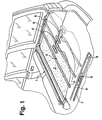
- Fig. 1
- zeigt in perspektivischer Darstellung eine Ausführungsform einer erfindungsgemäßen Schutzvorrichtung in Form einer Laderaumabdeckung,
- Fig. 2
- in schematischer Darstellung eine Draufsicht auf die Laderaumabdeckung nach Fig. 1,
- Fig. 3
- ebenfalls in schematischer Darstellung eine Seitenansicht der Schutzvorrichtung nach den Fig. 1 und 2,
- Fig. 4
- in vergrößerter, schematischer Darstellung einen Ausschnitt der Schutzvorrichtung nach Fig. 3 im Bereich eines Kupplungsgliedes,
- Fig. 5
- in schematischer Darstellung ähnlich Fig. 3 eine weitere Ausführungsform einer erfindungsgemäßen Schutzvorrichtung ähnlich Fig. 3,
- Fig. 6
- in vergrößerter, schematischer Darstellung einen Ausschnitt der Schutzvorrichtung nach Fig. 5 mit einem gegenüber der Fig. 4 geringfügig modifizierten Kupplungsglied,
- Fig. 7
- in schematischer Seitenansicht eine weitere Ausführungsform einer erfindungsgemäßen Schutzvorrichtung ähnlich den Fig. 3 und 5,
- Fig. 8
- in vergrößerter, schematischer Darstellung einen Ausschnitt der Schutzvorrichtung nach Fig. 7 im Bereich eines Kupplungsgliedes,
- Fig. 9 bis 11
- in einer Draufsicht von oben schematisch einen Ausschnitt einer Schutzvorrichtung gemäß einem Ausführungsbeispiel der Fig. 1 bis 8 im Bereich eines mit zwei Aufnahmeelementen versehenen Kupplungsgliedes in unterschiedlichen Momentanpositionen,
- Fig. 12
- in perspektivischer Darstellung eine weitere Ausführungsform einer erfindungsgemäßen Schutzvorrichtung, bei der die Kupplungsglieder für ein Anheben oder Absenken des Schutzgebildes in seitlichen Rahmenprofilen einer Heckklappe eines Kombi-Personenkraftwagens integriert sind.
Claims (8)
- Schutzvorrichtung für einen Innenraum eines Kraftfahrzeugs mit einem in einer Schutzposition zumindest weitgehend flächig aufgespannten Schutzgebilde (2), das mittels einer Antriebsvorrichtung (7, 9) zwischen wenigstens zwei Positionen beweglich gelagert ist, wobei mit dem Schutzgebilde (2) wenigstens ein Führungselement (4) verbunden ist, das mittels wenigstens eines Kupplungsgliedes (6, 6a, 6b, 6') mit Übertragungsmitteln (7) der Antriebsvorrichtung mitführbar ist,
dadurch gekennzeichnet, dass
das wenigstens eine Kupplungsglied (6, 6°, 6b 6') zum Mitführen des wenigstens einen Führungselementes (4) mit wenigstens einem Aufnahmeelement (11, 13; 11a, 13a; 11b, 13b) versehen ist, das eine begrenzte Kupplungskraft aufweist, bei deren Überschreitung das Führungselement (4) von dem Aufnahmeelement gelöst wird. - Schutzvorrichtung nach Anspruch 1, dadurch gekennzeichnet, daß jedes Kupplungsglied (6, 6a, 6b, 6') in einem fahrzeugfesten Führungsprofil (5, 5') linearbeweglich gelagert ist, dem auch das korrespondierende Führungselement (4, 4') zugeordnet ist.
- Schutzvorrichtung nach Anspruch 1 oder 2, dadurch gekennzeichnet, daß das wenigstens eine Aufnahmeelement (11, 13; 11a, 13a; 11b, 13b) des Kupplungsgliedes (6, 6a, 6b) mechanisch wirksam ist und zwischen einer Halteposition und einer Freigabeposition quer zur Bewegungsrichtung des Kupplungsgliedes (6, 6a, 6b) gegen die Kraft einer Rückstellfeder (12, 14; 12a, 14a; 12b, 14b) beweglich gelagert ist.
- Schutzvorrichtung nach Anspruch 1 oder 2, dadurch gekennzeichnet, daß zwei Kupplungsglieder (6, 6') auf gegenüberliegenden Seiten synchronisiert linearbeweglich angeordnet sind, die jeweils ein Führungselement (4, 4') des Schutzgebildes (2, 2') mitnehmen, freigeben oder aufnehmen.
- Schutzvorrichtung nach einem der vorhergehenden Ansprüche, dadurch gekennzeichnet, daß jedes Kupplungsglied (6, 6a, 6b) zwei Aufnahmeelemente (11, 13; 11a, 13a; 11b, 13b) aufweist, die auf entgegengesetzte Bewegungsrichtungen des Kupplungsgliedes (6, 6a, 6b) abgestimmt sind.
- Schutzvorrichtung nach Anspruch 5, dadurch gekennzeichnet, daß das eine Aufnahmeelement (13, 11a) bezüglich seiner Mitnahmekraft stärker ausgelegt ist als das andere Aufnahmeelement (11, 13a).
- Schutzvorrichtung nach einem der vorhergehenden Ansprüche, dadurch gekennzeichnet, daß dem wenigstens einen Führungselement (4, 4') wenigstens ein stationärer Anschlag (8, 15, 17, 19, 20) zur Sicherung des Schutzgebildes (2, 2') in verschiedenen Positionen zugeordnet ist, der mittels des wenigstens einen Kupplungsgliedes (6, 6a, 6b, 6') in eine die Bewegung des Schutzgebildes zulassende Freigabeposition überführbar ist.
- Schutzvorrichtung nach Anspruch 7, dadurch gekennzeichnet, daß die Anschläge als federbelastete, elastisch nachgiebige Sperrelemente gestaltet sind, die mit Anfahrschrägen für das jeweilige Kupplungsglied (6, 6a, 6b, 6') versehen sind.
Applications Claiming Priority (2)
| Application Number | Priority Date | Filing Date | Title |
|---|---|---|---|
| DE19944948A DE19944948C1 (de) | 1999-09-20 | 1999-09-20 | Schutzvorrichtung für einen Innenraum eines Kraftfahrzeuges |
| DE19944948 | 1999-09-20 |
Publications (3)
| Publication Number | Publication Date |
|---|---|
| EP1084907A2 EP1084907A2 (de) | 2001-03-21 |
| EP1084907A3 EP1084907A3 (de) | 2001-11-21 |
| EP1084907B1 true EP1084907B1 (de) | 2003-10-15 |
Family
ID=7922600
Family Applications (1)
| Application Number | Title | Priority Date | Filing Date |
|---|---|---|---|
| EP00117360A Expired - Lifetime EP1084907B1 (de) | 1999-09-20 | 2000-08-23 | Schutzvorrichtung für einen Innenraum eines Kraftfahrzeuges |
Country Status (5)
| Country | Link |
|---|---|
| US (1) | US6416103B1 (de) |
| EP (1) | EP1084907B1 (de) |
| JP (1) | JP3566642B2 (de) |
| KR (1) | KR100643845B1 (de) |
| DE (2) | DE19944948C1 (de) |
Cited By (1)
| Publication number | Priority date | Publication date | Assignee | Title |
|---|---|---|---|---|
| DE102015220192B3 (de) * | 2015-10-16 | 2017-03-09 | Bos Gmbh & Co. Kg | Schutzvorrichtung für einen Laderaum eines Kraftfahrzeugs |
Families Citing this family (74)
| Publication number | Priority date | Publication date | Assignee | Title |
|---|---|---|---|---|
| DE10038842A1 (de) * | 2000-08-04 | 2002-02-28 | Butz Peter Verwaltung | Laderaumabdeckung für Kraftwagen, insbesondere für Kombinations-Personenkraftwagen |
| DE10113621C1 (de) * | 2001-03-20 | 2002-10-10 | Butz Peter Verwaltung | Laderaumabdeckung für Kraftwagen, wie für Kombinations-Personenkraftwagen od. dgl. |
| DE10113616C1 (de) * | 2001-03-20 | 2002-10-10 | Butz Peter Verwaltung | Laderaumabdeckung für Kraftwagen, wie für Kombinations-Personenkraftwagen od. dgl. |
| US7928416B2 (en) * | 2006-12-22 | 2011-04-19 | Cymer, Inc. | Laser produced plasma EUV light source |
| DE10135273B4 (de) * | 2001-07-16 | 2005-10-13 | Bos Gmbh & Co. Kg | Schutzvorrichtung für einen Innenraumabschnitt eines Kraftfahrzeugs |
| JP4564690B2 (ja) * | 2001-08-02 | 2010-10-20 | 林テレンプ株式会社 | トノカバー装置 |
| DE10203743A1 (de) * | 2002-01-31 | 2003-08-21 | Stehle & Soehne Ag J | Anordnung einer Antriebseinheit zur Bewegung einer Abdeckung in einem Kraftfahrzeug |
| DE10204661B4 (de) * | 2002-02-05 | 2008-05-21 | Webasto Ag | Abdeckanordnung für einen Pritschenwagen |
| DE10229675B4 (de) * | 2002-06-27 | 2005-06-09 | Bos Gmbh & Co. Kg | Verriegelungseinrichtung für ein Kraftfahrzeug |
| DE10320108B4 (de) * | 2003-05-05 | 2006-12-28 | Webasto Ag | Kraftfahrzeug mit einer Abschottungseinrichtung |
| DE10324289A1 (de) * | 2003-05-21 | 2004-12-23 | Bayerische Motoren Werke Ag | Schutzvorrichtung für einen Innenraum eines Kraftfahrzeugs |
| DE10348892B4 (de) * | 2003-10-15 | 2006-07-06 | Bos Gmbh & Co. Kg | Schutzvorrichtung für einen Laderaum eines Kraftfahrzeugs |
| DE10356911B3 (de) * | 2003-12-02 | 2005-01-20 | Bos Gmbh & Co. Kg | Laderaumschutzvorrichtung für ein Kraftfahrzeug |
| DE102004008874A1 (de) * | 2004-02-18 | 2005-09-08 | Bos Gmbh & Co. Kg | Funktionseinheit für einen Fahrzeuginnenraum |
| FR2866276B1 (fr) * | 2004-02-18 | 2006-04-28 | Wagon Sas | Dispositif d'occultation pour vehicule automobile, et vehicule correspondant |
| FR2875758B1 (fr) * | 2004-09-29 | 2006-12-29 | Cera | Systeme de montage d'un cache-bagages comprenant un rail annexe |
| DE102004057112A1 (de) * | 2004-11-26 | 2006-06-01 | Acts Advanced Car Technology Systems Gmbh & Co.Kg | Vorrichtung zur Sicherung von Ladegut in einem Kraftfahrzeug |
| DE102006009417B4 (de) * | 2005-03-02 | 2009-08-13 | Bos Gmbh & Co. Kg | Laderaumabdeckung für ein Kraftfahrzeug |
| DE502006000664D1 (de) * | 2005-03-02 | 2008-06-05 | Bos Gmbh | Laderaumabdeckung für ein Kraftfahrzeug |
| US20060215411A1 (en) * | 2005-03-22 | 2006-09-28 | Tera Autotech Corporation | LED lamp assembly |
| DE102005018977A1 (de) * | 2005-04-23 | 2006-11-02 | Bayerische Motoren Werke Ag | Verriegelungseinrichtung für ein ausziehbares Abdeckelement, insbesondere im Gepäckraum eines Kraftfahrzeugs |
| DE102005031070B4 (de) * | 2005-06-24 | 2012-02-23 | Bos Gmbh & Co. Kg | Laderaumfunktionsvorrichtung für ein Kraftfahrzeug |
| DE102005049999A1 (de) * | 2005-10-13 | 2007-04-26 | Bos Gmbh & Co. Kg | Abdeckvorrichtung für einen Laderaum eines Kraftfahrzeugs |
| EP1787864B1 (de) * | 2005-11-22 | 2009-03-25 | Mazda Motor Corporation | Hintere Struktur eines Kraftfahrzeugs |
| DE102005055625C5 (de) * | 2005-11-22 | 2010-05-20 | Bayerische Motoren Werke Aktiengesellschaft | Laderaumabdeckung für ein Fahrzeug |
| DE102005056334C5 (de) * | 2005-11-25 | 2008-11-13 | Webasto Ag | Vorrichtung zur Sicherung von Ladegut |
| WO2007070951A1 (en) * | 2005-12-21 | 2007-06-28 | Tulli Pty Ltd | Automobile surface protector having adjustable width |
| DE102006009755B3 (de) * | 2006-03-02 | 2007-09-13 | Webasto Ag | Laderaumabtrennung |
| DE102006015546B4 (de) * | 2006-03-31 | 2015-07-02 | Toyota Boshoku Kabushiki Kaisha | Anordnung zum Verfahren eines Laderaumabdeckelements |
| DE102006017627B4 (de) * | 2006-04-12 | 2008-12-18 | Automotive Group Ise Innomotive Systems Europe Gmbh | Laderaumabtrennung und Sicherungseinheit für eine Laderaumabtrennung für Kraftfahrzeuge |
| DE102006019322B4 (de) * | 2006-04-24 | 2008-02-21 | Webasto Ag | Fahrzeugdach mit einem bewegbaren Deckel und einem unter diesem angeordneten öffnungsfähigen Rollo |
| JP4247751B2 (ja) | 2006-08-10 | 2009-04-02 | トヨタ紡織株式会社 | サンシェード装置 |
| DE102006045219B4 (de) * | 2006-09-25 | 2008-09-04 | Maxon Motor Gmbh | Antriebsvorrichtung für eine Laderaumabdeckung |
| ATE505354T1 (de) | 2006-09-27 | 2011-04-15 | Bos Gmbh | Manuell betätiges fensterrollo |
| DE102006053680A1 (de) * | 2006-11-13 | 2008-05-15 | Bos Gmbh & Co. Kg | Automatisch öffnende Laderaumabdeckung |
| DE102006046069A1 (de) * | 2006-09-27 | 2008-04-10 | Bos Gmbh & Co. Kg | Fensterrollo mit reibungsmindertem Antrieb |
| DE102006047348A1 (de) | 2006-09-29 | 2008-04-03 | Brose Fahrzeugteile Gmbh & Co. Kommanditgesellschaft, Coburg | Antriebsvorrichtung zum Bewegen eines Abdeckelementes, Türbaugruppe und Verfahren zur Montage der Antriebsvorrichtung |
| US7673921B2 (en) * | 2007-01-24 | 2010-03-09 | Mazda Motor Corporation | Tonneau cover device of vehicle |
| DE102007021428B4 (de) * | 2007-05-03 | 2012-08-30 | Bos Gmbh & Co. Kg | Abdeckungssystem für einen Heckstauraum eines Fahrzeugs |
| DE102007039859B4 (de) * | 2007-08-23 | 2025-07-17 | Dr. Ing. H.C. F. Porsche Aktiengesellschaft | Abdeckanordnung und Kraftfahrzeug |
| DE102007040282C9 (de) | 2007-08-24 | 2016-03-10 | Küster Holding GmbH | Abdeckeinrichtung für den Fahrzeuginnenraum |
| DE102007048008A1 (de) * | 2007-09-27 | 2009-04-09 | Bos Gmbh & Co. Kg | Flächengebilde für eine Schutzvorrichtung in einem Fahrzeuginnenraum |
| DE102007057073B4 (de) * | 2007-11-23 | 2011-12-29 | Bos Gmbh & Co. Kg | Abdecksystem für ein Fahrzeug |
| DE102007057080B4 (de) * | 2007-11-23 | 2010-04-08 | Bos Gmbh & Co. Kg | Rollosystem |
| DE102007057074A1 (de) | 2007-11-23 | 2009-06-04 | Bos Gmbh & Co. Kg | Rollosystem |
| DE102008025739A1 (de) * | 2008-05-29 | 2009-12-03 | GM Global Technology Operations, Inc., Detroit | Antriebskassette und Laderaumseitenverkleidungsteil für eine automatische Laderaumabdeckvorrichtung |
| DE102009023723A1 (de) * | 2009-06-03 | 2010-12-09 | Bayerische Motoren Werke Aktiengesellschaft | Kraftfahrzeug |
| JP2012206675A (ja) * | 2011-03-30 | 2012-10-25 | Tokai Rika Co Ltd | トノカバー装置 |
| DE102011076802B4 (de) | 2011-05-31 | 2013-02-21 | Bos Gmbh & Co. Kg | Schutzvorrichtung für einen Fahrzeuginnenraum |
| US20130153160A1 (en) * | 2011-11-18 | 2013-06-20 | Macauto Industrial Co., Ltd. | Sunshade assembly |
| TWM428992U (en) * | 2011-12-08 | 2012-05-11 | Macauto Ind Co Ltd | Track type sunshade device |
| DE102012202292A1 (de) * | 2012-02-15 | 2013-08-22 | Brose Fahrzeugteile Gmbh & Co. Kommanditgesellschaft, Coburg | Verstelleinrichtung für eine Laderaumabdeckung |
| KR101382879B1 (ko) * | 2012-03-05 | 2014-04-08 | 한일이화주식회사 | 차량용 전동식 카고스크린 이송장치 |
| JP6143465B2 (ja) * | 2012-04-26 | 2017-06-07 | 芦森工業株式会社 | シート引出収納装置 |
| DE102013200769A1 (de) | 2013-01-18 | 2014-07-24 | Brose Fahrzeugteile Gmbh & Co. Kg, Coburg | Verstellvorrichtung mit einer ein Endstück aufweisenden Abdeckung für einen Laderaum eines Fahrzeugs |
| DE102014211163B4 (de) | 2013-06-28 | 2023-12-21 | Bos Gmbh & Co. Kg | Schutzvorrichtung für einen Laderaum eines Kraftfahrzeugs sowie Antriebsvorrichtung hierfür |
| US9731584B2 (en) | 2015-02-13 | 2017-08-15 | Bos Automotive Products, Inc. | Automated soft tonneau cover |
| EP3075601B1 (de) * | 2015-03-30 | 2017-07-12 | Toyota Boshoku Kabushiki Kaisha | Layoutsystem für laderaum eines fahrzeugs |
| DE102015208627B3 (de) * | 2015-05-08 | 2016-07-07 | Bos Gmbh & Co. Kg | Schutzvorrichtung für einen Fahrzeuginnenraum |
| DE102015110892B4 (de) * | 2015-07-06 | 2023-08-17 | Bayerische Motoren Werke Aktiengesellschaft | Abdeckvorrichtung zum Abdecken eines Laderaums eines Kraftfahrzeugs |
| DE102015118305B4 (de) * | 2015-10-01 | 2025-07-24 | Fkt Gmbh | Abtrennvorrichtung für einen Laderaum eines Kraftfahrzeugs |
| DE102015118775B4 (de) * | 2015-11-03 | 2019-02-21 | Macauto Industrial Co., Ltd. | Laderaumabdeckung |
| DE102016006026B3 (de) | 2016-05-17 | 2017-03-30 | Audi Ag | Laderaumabdeckung für ein Kraftfahrzeug |
| DE102016215599B3 (de) * | 2016-08-19 | 2017-07-27 | Bos Gmbh & Co. Kg | Schutzvorrichtung für einen Fahrzeuginnenraum |
| EP3519218B1 (de) * | 2016-09-27 | 2020-07-29 | Stokbro BYG Invest/Jeppe Stokbro | Fahrzeug mit mindestens einer verriegelbaren tür |
| DE102016219504B4 (de) | 2016-10-07 | 2020-08-06 | Bos Gmbh & Co. Kg | Laderaumabdeckvorrichtung für ein Kraftfahrzeug |
| US11142050B2 (en) | 2018-06-21 | 2021-10-12 | Bos Automotive Products, Inc. | Rigid tonneau cover |
| US11318826B2 (en) | 2017-02-24 | 2022-05-03 | Bos Automotive Products, Inc. | Stacking rigid cover |
| WO2018156921A1 (en) | 2017-02-24 | 2018-08-30 | Bos Automotive Products, Inc. | Automated rigid tonneau cover |
| US11884145B2 (en) | 2017-02-24 | 2024-01-30 | Bos Automotive Products, Inc. | Stacking rigid cover |
| US10982450B2 (en) * | 2017-05-24 | 2021-04-20 | Charlie Burnside | Retractable floor cover |
| KR102739204B1 (ko) * | 2018-12-14 | 2024-12-05 | 현대자동차주식회사 | 차량의 카고 스크린 어셈블리 |
| FR3096631B1 (fr) | 2019-05-31 | 2021-11-12 | Inteva Products France Sas | Cache-bagages motorisé pour vehicule |
| DE102020101952B4 (de) * | 2020-01-28 | 2025-06-18 | Bayerische Motoren Werke Aktiengesellschaft | Verfahren zum Bereitstellen eines Einklemmschutzes für ein Kraftfahrzeug |
Family Cites Families (8)
| Publication number | Priority date | Publication date | Assignee | Title |
|---|---|---|---|---|
| US3819082A (en) * | 1972-01-28 | 1974-06-25 | L Rosenvold | Truck box cover device |
| DE3505143A1 (de) * | 1985-02-14 | 1986-08-14 | Zalzar GmbH, 8000 München | Vorrichtung zur fuehrung einer gardine oder dergleichen, insbesondere an kraftfahrzeugscheiben |
| EP0548148B1 (de) * | 1990-09-21 | 1996-12-11 | PETTERSON, Kalervo | Plattformabdeckvorrichtung |
| ES2150324B1 (es) * | 1996-07-09 | 2001-06-16 | Sanchez Jose Francisco Seoane | Sistema de toldaje y destoldaje de lonas para vehiculos de transporte de mercancias. |
| DE19650775C2 (de) | 1996-12-06 | 1999-03-11 | Baumeister & Ostler Gmbh Co | Abdeckrollo mit vereinfachter Bedienung |
| DE19825353C2 (de) * | 1997-06-17 | 2001-10-25 | Butz Peter Verwaltung | Laderaumabdeckung für Kraftfahrzeuge, insbesondere für Kombinations-Personenkraftwagen od. dgl. |
| US6003920A (en) | 1997-06-17 | 1999-12-21 | Peter Butz Gmbh & Co. | Cargo-space cover for motor vehicle |
| DE29818442U1 (de) * | 1997-10-17 | 1999-02-18 | Peter Butz Gmbh & Co Verwaltungs-Kg, 40764 Langenfeld | Laderaumabdeckung, wie Abdeckrollo o.dgl., für den Lade- bzw. Kofferraum eines Fahrzeugs |
-
1999
- 1999-09-20 DE DE19944948A patent/DE19944948C1/de not_active Expired - Fee Related
-
2000
- 2000-08-23 EP EP00117360A patent/EP1084907B1/de not_active Expired - Lifetime
- 2000-08-23 DE DE50004059T patent/DE50004059D1/de not_active Expired - Lifetime
- 2000-09-20 US US09/666,531 patent/US6416103B1/en not_active Expired - Lifetime
- 2000-09-20 KR KR1020000055269A patent/KR100643845B1/ko not_active Expired - Fee Related
- 2000-09-20 JP JP2000285394A patent/JP3566642B2/ja not_active Expired - Fee Related
Cited By (2)
| Publication number | Priority date | Publication date | Assignee | Title |
|---|---|---|---|---|
| DE102015220192B3 (de) * | 2015-10-16 | 2017-03-09 | Bos Gmbh & Co. Kg | Schutzvorrichtung für einen Laderaum eines Kraftfahrzeugs |
| EP3156284A1 (de) | 2015-10-16 | 2017-04-19 | BOS GmbH & Co. KG | Schutzvorrichtung für einen laderaum eines kraftfahrzeugs |
Also Published As
| Publication number | Publication date |
|---|---|
| DE50004059D1 (de) | 2003-11-20 |
| JP2001122027A (ja) | 2001-05-08 |
| EP1084907A3 (de) | 2001-11-21 |
| JP3566642B2 (ja) | 2004-09-15 |
| KR20010050539A (ko) | 2001-06-15 |
| KR100643845B1 (ko) | 2006-11-10 |
| EP1084907A2 (de) | 2001-03-21 |
| US6416103B1 (en) | 2002-07-09 |
| DE19944948C1 (de) | 2001-05-31 |
Similar Documents
| Publication | Publication Date | Title |
|---|---|---|
| EP1084907B1 (de) | Schutzvorrichtung für einen Innenraum eines Kraftfahrzeuges | |
| EP0941176B1 (de) | Abdeckrollo mit vereinfachter bedienung | |
| EP1250509B1 (de) | Sektionalhub- oder falttor | |
| EP0658679B1 (de) | Sicherung für aus Stäben zusammengesetzte Rollade, -tor oder -tür | |
| DE10356911B3 (de) | Laderaumschutzvorrichtung für ein Kraftfahrzeug | |
| EP1524152A1 (de) | Laderaumabdeckung | |
| DE102004024382B4 (de) | Fahrzeug-Rollosystem | |
| EP2062781A1 (de) | Abdecksystem für ein Fahrzeug | |
| DE102009057014A1 (de) | Vorrichtung zum Schließen einer absenkbaren Schütte eines Gepäckfachs | |
| DE10256348A1 (de) | Öffnungsloser Klappgriff | |
| DE202015006895U1 (de) | Aufstellbares Klappenscharnier | |
| EP1951551A1 (de) | Laderaumabdeckung für ein fahrzeug | |
| EP1373668A1 (de) | Sicherungsvorrichtung | |
| DE2103820A1 (de) | Rolladen | |
| DE102006024641A1 (de) | Schutzeinrichtung für Kraftfahrzeuge | |
| DE102017208711A1 (de) | Sektionaltor, umfassend eine Tür und eine passive mechanische Sicherheitsvorrichtung, welche darauf abzielt, das Öffnen der Tür in geöffneter Position des Torflügels eines solchen Tors zu verhindern und/oder zu begrenzen. | |
| DE69902751T2 (de) | Verbesserte sicherheitsanordnungen | |
| DE102012221585B4 (de) | Rückhaltevorrichtung für einen Fahrzeuginnenraum | |
| EP2325429A2 (de) | Verdeckantrieb | |
| DE102010062840B4 (de) | Windschutzeinrichtung | |
| DE102021131274B3 (de) | Warenübergabeschleuse | |
| EP1128015A2 (de) | Parallelschiebefenster- oder -türe | |
| EP1334876B1 (de) | Sicherheitsnetz zur Abtrennung eines Laderaums von einer Fahrgastzelle in einem Kraftfahrzeug | |
| DE19626582C2 (de) | Kraftfahrzeug mit einem Laderaum und Laderaumabdeckung | |
| DE102018008376A1 (de) | Beschattungsvorrichtung für eine Scheibe eines Kraftfahrzeugs |
Legal Events
| Date | Code | Title | Description |
|---|---|---|---|
| PUAI | Public reference made under article 153(3) epc to a published international application that has entered the european phase |
Free format text: ORIGINAL CODE: 0009012 |
|
| AK | Designated contracting states |
Kind code of ref document: A2 Designated state(s): AT BE CH CY DE DK ES FI FR GB GR IE IT LI LU MC NL PT SE Kind code of ref document: A2 Designated state(s): DE FR GB IT |
|
| AX | Request for extension of the european patent |
Free format text: AL;LT;LV;MK;RO;SI |
|
| PUAL | Search report despatched |
Free format text: ORIGINAL CODE: 0009013 |
|
| AK | Designated contracting states |
Kind code of ref document: A3 Designated state(s): AT BE CH CY DE DK ES FI FR GB GR IE IT LI LU MC NL PT SE |
|
| AX | Request for extension of the european patent |
Free format text: AL;LT;LV;MK;RO;SI |
|
| 17P | Request for examination filed |
Effective date: 20020508 |
|
| AKX | Designation fees paid |
Free format text: DE FR GB IT |
|
| 17Q | First examination report despatched |
Effective date: 20020725 |
|
| GRAH | Despatch of communication of intention to grant a patent |
Free format text: ORIGINAL CODE: EPIDOS IGRA |
|
| GRAH | Despatch of communication of intention to grant a patent |
Free format text: ORIGINAL CODE: EPIDOS IGRA |
|
| GRAA | (expected) grant |
Free format text: ORIGINAL CODE: 0009210 |
|
| AK | Designated contracting states |
Kind code of ref document: B1 Designated state(s): DE FR GB IT |
|
| REG | Reference to a national code |
Ref country code: GB Ref legal event code: FG4D Free format text: NOT ENGLISH |
|
| REF | Corresponds to: |
Ref document number: 50004059 Country of ref document: DE Date of ref document: 20031120 Kind code of ref document: P |
|
| GBT | Gb: translation of ep patent filed (gb section 77(6)(a)/1977) |
Effective date: 20040123 |
|
| ET | Fr: translation filed | ||
| PLBE | No opposition filed within time limit |
Free format text: ORIGINAL CODE: 0009261 |
|
| STAA | Information on the status of an ep patent application or granted ep patent |
Free format text: STATUS: NO OPPOSITION FILED WITHIN TIME LIMIT |
|
| 26N | No opposition filed |
Effective date: 20040716 |
|
| PGFP | Annual fee paid to national office [announced via postgrant information from national office to epo] |
Ref country code: GB Payment date: 20120823 Year of fee payment: 13 |
|
| PGFP | Annual fee paid to national office [announced via postgrant information from national office to epo] |
Ref country code: FR Payment date: 20120831 Year of fee payment: 13 Ref country code: IT Payment date: 20120824 Year of fee payment: 13 |
|
| GBPC | Gb: european patent ceased through non-payment of renewal fee |
Effective date: 20130823 |
|
| REG | Reference to a national code |
Ref country code: FR Ref legal event code: ST Effective date: 20140430 |
|
| PG25 | Lapsed in a contracting state [announced via postgrant information from national office to epo] |
Ref country code: IT Free format text: LAPSE BECAUSE OF NON-PAYMENT OF DUE FEES Effective date: 20130823 |
|
| PG25 | Lapsed in a contracting state [announced via postgrant information from national office to epo] |
Ref country code: GB Free format text: LAPSE BECAUSE OF NON-PAYMENT OF DUE FEES Effective date: 20130823 |
|
| PG25 | Lapsed in a contracting state [announced via postgrant information from national office to epo] |
Ref country code: FR Free format text: LAPSE BECAUSE OF NON-PAYMENT OF DUE FEES Effective date: 20130902 |
|
| PGFP | Annual fee paid to national office [announced via postgrant information from national office to epo] |
Ref country code: DE Payment date: 20160829 Year of fee payment: 17 |
|
| REG | Reference to a national code |
Ref country code: DE Ref legal event code: R119 Ref document number: 50004059 Country of ref document: DE |
|
| PG25 | Lapsed in a contracting state [announced via postgrant information from national office to epo] |
Ref country code: DE Free format text: LAPSE BECAUSE OF NON-PAYMENT OF DUE FEES Effective date: 20180301 |