EP3147101B1 - Process for forming one or more air intake holes in a laminated, blow-molded container - Google Patents
Process for forming one or more air intake holes in a laminated, blow-molded container Download PDFInfo
- Publication number
- EP3147101B1 EP3147101B1 EP16002214.1A EP16002214A EP3147101B1 EP 3147101 B1 EP3147101 B1 EP 3147101B1 EP 16002214 A EP16002214 A EP 16002214A EP 3147101 B1 EP3147101 B1 EP 3147101B1
- Authority
- EP
- European Patent Office
- Prior art keywords
- outer layer
- air intake
- cylindrical blade
- punch
- blade
- Prior art date
- Legal status (The legal status is an assumption and is not a legal conclusion. Google has not performed a legal analysis and makes no representation as to the accuracy of the status listed.)
- Active
Links
- 238000000034 method Methods 0.000 title claims description 36
- 230000002093 peripheral effect Effects 0.000 claims description 19
- 229920003002 synthetic resin Polymers 0.000 claims description 12
- 239000000057 synthetic resin Substances 0.000 claims description 12
- 238000005520 cutting process Methods 0.000 description 21
- 230000001788 irregular Effects 0.000 description 16
- 238000010586 diagram Methods 0.000 description 7
- 229920005989 resin Polymers 0.000 description 4
- 239000011347 resin Substances 0.000 description 4
- 230000007423 decrease Effects 0.000 description 3
- 229920001903 high density polyethylene Polymers 0.000 description 3
- 239000004700 high-density polyethylene Substances 0.000 description 3
- 238000000071 blow moulding Methods 0.000 description 2
- 230000000694 effects Effects 0.000 description 2
- 230000002349 favourable effect Effects 0.000 description 2
- 239000012530 fluid Substances 0.000 description 2
- 238000003475 lamination Methods 0.000 description 2
- 238000010008 shearing Methods 0.000 description 2
- 239000004677 Nylon Substances 0.000 description 1
- 230000001419 dependent effect Effects 0.000 description 1
- 230000009977 dual effect Effects 0.000 description 1
- 238000004519 manufacturing process Methods 0.000 description 1
- 239000000463 material Substances 0.000 description 1
- 238000000465 moulding Methods 0.000 description 1
- 229920001778 nylon Polymers 0.000 description 1
- 238000004080 punching Methods 0.000 description 1
- 238000011084 recovery Methods 0.000 description 1
Images


Classifications
-
- B—PERFORMING OPERATIONS; TRANSPORTING
- B65—CONVEYING; PACKING; STORING; HANDLING THIN OR FILAMENTARY MATERIAL
- B65D—CONTAINERS FOR STORAGE OR TRANSPORT OF ARTICLES OR MATERIALS, e.g. BAGS, BARRELS, BOTTLES, BOXES, CANS, CARTONS, CRATES, DRUMS, JARS, TANKS, HOPPERS, FORWARDING CONTAINERS; ACCESSORIES, CLOSURES, OR FITTINGS THEREFOR; PACKAGING ELEMENTS; PACKAGES
- B65D1/00—Containers having bodies formed in one piece, e.g. by casting metallic material, by moulding plastics, by blowing vitreous material, by throwing ceramic material, by moulding pulped fibrous material, by deep-drawing operations performed on sheet material
- B65D1/02—Bottles or similar containers with necks or like restricted apertures, designed for pouring contents
- B65D1/0223—Bottles or similar containers with necks or like restricted apertures, designed for pouring contents characterised by shape
- B65D1/023—Neck construction
-
- B—PERFORMING OPERATIONS; TRANSPORTING
- B26—HAND CUTTING TOOLS; CUTTING; SEVERING
- B26F—PERFORATING; PUNCHING; CUTTING-OUT; STAMPING-OUT; SEVERING BY MEANS OTHER THAN CUTTING
- B26F1/00—Perforating; Punching; Cutting-out; Stamping-out; Apparatus therefor
- B26F1/02—Perforating by punching, e.g. with relatively-reciprocating punch and bed
-
- B—PERFORMING OPERATIONS; TRANSPORTING
- B29—WORKING OF PLASTICS; WORKING OF SUBSTANCES IN A PLASTIC STATE IN GENERAL
- B29C—SHAPING OR JOINING OF PLASTICS; SHAPING OF MATERIAL IN A PLASTIC STATE, NOT OTHERWISE PROVIDED FOR; AFTER-TREATMENT OF THE SHAPED PRODUCTS, e.g. REPAIRING
- B29C49/00—Blow-moulding, i.e. blowing a preform or parison to a desired shape within a mould; Apparatus therefor
- B29C49/42—Component parts, details or accessories; Auxiliary operations
- B29C49/4273—Auxiliary operations after the blow-moulding operation not otherwise provided for
-
- B—PERFORMING OPERATIONS; TRANSPORTING
- B65—CONVEYING; PACKING; STORING; HANDLING THIN OR FILAMENTARY MATERIAL
- B65D—CONTAINERS FOR STORAGE OR TRANSPORT OF ARTICLES OR MATERIALS, e.g. BAGS, BARRELS, BOTTLES, BOXES, CANS, CARTONS, CRATES, DRUMS, JARS, TANKS, HOPPERS, FORWARDING CONTAINERS; ACCESSORIES, CLOSURES, OR FITTINGS THEREFOR; PACKAGING ELEMENTS; PACKAGES
- B65D1/00—Containers having bodies formed in one piece, e.g. by casting metallic material, by moulding plastics, by blowing vitreous material, by throwing ceramic material, by moulding pulped fibrous material, by deep-drawing operations performed on sheet material
- B65D1/02—Bottles or similar containers with necks or like restricted apertures, designed for pouring contents
- B65D1/0207—Bottles or similar containers with necks or like restricted apertures, designed for pouring contents characterised by material, e.g. composition, physical features
- B65D1/0215—Bottles or similar containers with necks or like restricted apertures, designed for pouring contents characterised by material, e.g. composition, physical features multilayered
-
- B—PERFORMING OPERATIONS; TRANSPORTING
- B65—CONVEYING; PACKING; STORING; HANDLING THIN OR FILAMENTARY MATERIAL
- B65D—CONTAINERS FOR STORAGE OR TRANSPORT OF ARTICLES OR MATERIALS, e.g. BAGS, BARRELS, BOTTLES, BOXES, CANS, CARTONS, CRATES, DRUMS, JARS, TANKS, HOPPERS, FORWARDING CONTAINERS; ACCESSORIES, CLOSURES, OR FITTINGS THEREFOR; PACKAGING ELEMENTS; PACKAGES
- B65D77/00—Packages formed by enclosing articles or materials in preformed containers, e.g. boxes, cartons, sacks or bags
- B65D77/04—Articles or materials enclosed in two or more containers disposed one within another
-
- B—PERFORMING OPERATIONS; TRANSPORTING
- B65—CONVEYING; PACKING; STORING; HANDLING THIN OR FILAMENTARY MATERIAL
- B65D—CONTAINERS FOR STORAGE OR TRANSPORT OF ARTICLES OR MATERIALS, e.g. BAGS, BARRELS, BOTTLES, BOXES, CANS, CARTONS, CRATES, DRUMS, JARS, TANKS, HOPPERS, FORWARDING CONTAINERS; ACCESSORIES, CLOSURES, OR FITTINGS THEREFOR; PACKAGING ELEMENTS; PACKAGES
- B65D77/00—Packages formed by enclosing articles or materials in preformed containers, e.g. boxes, cartons, sacks or bags
- B65D77/22—Details
- B65D77/225—Pressure relief-valves incorporated in a container wall, e.g. valves comprising at least one elastic element
-
- B—PERFORMING OPERATIONS; TRANSPORTING
- B26—HAND CUTTING TOOLS; CUTTING; SEVERING
- B26F—PERFORATING; PUNCHING; CUTTING-OUT; STAMPING-OUT; SEVERING BY MEANS OTHER THAN CUTTING
- B26F2210/00—Perforating, punching, cutting-out, stamping-out, severing by means other than cutting of specific products
-
- B—PERFORMING OPERATIONS; TRANSPORTING
- B29—WORKING OF PLASTICS; WORKING OF SUBSTANCES IN A PLASTIC STATE IN GENERAL
- B29C—SHAPING OR JOINING OF PLASTICS; SHAPING OF MATERIAL IN A PLASTIC STATE, NOT OTHERWISE PROVIDED FOR; AFTER-TREATMENT OF THE SHAPED PRODUCTS, e.g. REPAIRING
- B29C2793/00—Shaping techniques involving a cutting or machining operation
- B29C2793/0009—Cutting out
- B29C2793/0018—Cutting out for making a hole
-
- B—PERFORMING OPERATIONS; TRANSPORTING
- B29—WORKING OF PLASTICS; WORKING OF SUBSTANCES IN A PLASTIC STATE IN GENERAL
- B29C—SHAPING OR JOINING OF PLASTICS; SHAPING OF MATERIAL IN A PLASTIC STATE, NOT OTHERWISE PROVIDED FOR; AFTER-TREATMENT OF THE SHAPED PRODUCTS, e.g. REPAIRING
- B29C2793/00—Shaping techniques involving a cutting or machining operation
- B29C2793/009—Shaping techniques involving a cutting or machining operation after shaping
-
- B—PERFORMING OPERATIONS; TRANSPORTING
- B29—WORKING OF PLASTICS; WORKING OF SUBSTANCES IN A PLASTIC STATE IN GENERAL
- B29C—SHAPING OR JOINING OF PLASTICS; SHAPING OF MATERIAL IN A PLASTIC STATE, NOT OTHERWISE PROVIDED FOR; AFTER-TREATMENT OF THE SHAPED PRODUCTS, e.g. REPAIRING
- B29C2949/00—Indexing scheme relating to blow-moulding
- B29C2949/30—Preforms or parisons made of several components
- B29C2949/3086—Interaction between two or more components, e.g. type of or lack of bonding
- B29C2949/3094—Interaction between two or more components, e.g. type of or lack of bonding preform having at least partially loose components, e.g. at least partially loose layers
-
- B—PERFORMING OPERATIONS; TRANSPORTING
- B29—WORKING OF PLASTICS; WORKING OF SUBSTANCES IN A PLASTIC STATE IN GENERAL
- B29C—SHAPING OR JOINING OF PLASTICS; SHAPING OF MATERIAL IN A PLASTIC STATE, NOT OTHERWISE PROVIDED FOR; AFTER-TREATMENT OF THE SHAPED PRODUCTS, e.g. REPAIRING
- B29C49/00—Blow-moulding, i.e. blowing a preform or parison to a desired shape within a mould; Apparatus therefor
- B29C49/22—Blow-moulding, i.e. blowing a preform or parison to a desired shape within a mould; Apparatus therefor using multilayered preforms or parisons
-
- B—PERFORMING OPERATIONS; TRANSPORTING
- B29—WORKING OF PLASTICS; WORKING OF SUBSTANCES IN A PLASTIC STATE IN GENERAL
- B29L—INDEXING SCHEME ASSOCIATED WITH SUBCLASS B29C, RELATING TO PARTICULAR ARTICLES
- B29L2009/00—Layered products
- B29L2009/001—Layered products the layers being loose
Definitions
- This invention relates to a laminated, blow-molded container, which comprises an outer layer of a synthetic resin that forms an outer shell in a fixed shape and an inner layer that forms an inner bag to be laminated with this outer layer in a peelable manner, wherein one or more air intake holes is/are cut out in the neck to take outside air into the interspace between the outer layer and the inner layer, and to a process for forming these air intake holes.
- the laminated, blow-molded containers comprising a synthetic-resin outer layer forming an outer shell of a fixed shape and an inner layer forming an inner bag to be laminated with this outer layer in a peelable manner, i.e., the so-called easy-to-delaminate bottles, are known.
- Document JP 1996-244102 describes a process and the equipment for punch-cutting one or more air intake holes in a portion of the outer layer in the neck to take in outside air.
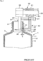
- Fig. 9 is an explanatory diagram showing schematically the process for forming an air intake hole.
- This diagram corresponds to Fig. 2 of the patent document D1 and shows a laminated, blow-molded container 1 along with a punch-cutting machine 30.
- the container 1 is an easy-to-delaminate bottle comprising a neck 2, a shoulder 3, and a body 4 and having the outer layer 11 laminated with the inner layer 12.
- the punch-cutting machine 30 mainly comprises a stationary member 31 and a cutting member 40 shown by a hatched area in the vertical section of Fig. 9 .
- the stationary member 31 comprises a support rod 34 hanging downward from a support member 32 and a cutter stop 36 disposed at a lower end portion of this support rod 34.
- the cutting member 40 comprises a sliding member 41, which is supported in a manner slidable from side to side by a support shaft 33 disposed horizontally and fitted to the support member 32, a cutter holder 42 hanging downward from this sliding member 41, and a punch-cutter 43 disposed at a lower end portion of the cutter holder 42 so that the punch-cutter 43 is opposed to the cutter stop 36 of the stationary member 31.
- the punch-cutter 43 has a cylindrical blade 44 at the tip and a through-hole 46 to take out a cut piece 11a.
- a driving means (not shown) is used to move the sliding member 41 to the left (in the X direction in Fig. 9 ) along the support shaft 33, the punch-cutter 43 also moves until the front face of a bolt 37 bumps into the support rod 34.
- the cylindrical blade 44 presses the inner layer 12 of the neck 2 of the container 1 against an opposed surface 36a of the cutter stop 36.
- the blade 44 cuts into the outer layer 11 of the neck 2 of the container 1 forcibly, and cuts out a piece of the outer layer 11 while leaving the inner layer 12 intact, thus forming one or more air intake holes to take outside air into the interspace between the inner layer 12 and the outer layer 11.
- the air intake hole can be formed solely in the outer layer 11 by adjusting the bolt 37 to set a gap, t, between the blade edge of the cylindrical blade 44 of the punch-cutter 43 and the opposed surface 36a, at a length equivalent to the thickness of the inner layer 12.
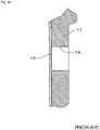
- Fig. 10 is a vertical section showing a state of lamination of the outer layer 11 and the inner layer 12 near an air intake hole 14 that has been formed as described above.
- the easy-to-delaminate bottles of this kind have the inner layer 12 and the outer layer 11 that should be peelable from each other, but in fact are in tight contact in many cases. Therefore, in some of the dispensing container products utilizing the easy-to-delaminate bottles of this kind, it is often difficult, after a content fluid has been dispensed, to utilize a pressure drop inside the bottle so as to take outside air smoothly into the interspace between the outer layer 11 and the inner layer 12 through one or more air intake holes 14.
- a vacuum pump and the like are used in many cases to suck air through the neck 2 in order to put the bottle inside forcibly under a reduced pressure condition. This causes the outer layer 11 and the inner layer 12 to be peeled from each other, and tentatively releases the tight contact of these layers over the entire region. Thereafter, air is blown through the neck 2 to bring the outer layer 11 and the inner layer 12 back to a laminated state.
- Document EP 0 759 399 A1 describes a process for forming a laminated container with an outside resin layer having an air inlet and an inside resin layer, wherein the air inlet is formed by punching from the outside of the outside layer at a mouth portion of the laminated peel container and cutting only the outside layer.
- JP 2006182389 A describes a process for manufacturing of a blow-molded container which comprises an external layer and an internal layer and which has an internal bag.
- the blow-molded container is formed with an air suction hole in a protruding section which is placed under a pressed state from the external layer section.
- the air intake holes can be cut out in the outer layer 11 alone, despite of the fluctuations in the thickness, once the gap, t, in Fig. 9 has been set at a minimum thickness of the inner layer 12. Practically, however, this process requires that the blade edge of the punch-cutter comes in direct contact with the outer peripheral surface of the inner layer 12 to cut out holes through the outer layer 11 completely. Under such a condition, a vestige of cut could remain in the inner layer 12, and there may be a fear that the thinned inner layer 12 would be broken. Besides, there is another problem in that the punch-cutting of the outer layer 11 creates cutting chips, which are difficult to remove. These remaining chips are also inconvenient for the air intake holes to open easily.
- a first technical problem of this invention is to create a shape of the air intake holes so that the peeling of the inner layer from the outer layer would go on smoothly and reliably around an inside opening of each air intake hole on the inner-surface side of the outer layer.
- Another technical problem is to create a process for forming one or more air intake holes, while keeping the inner layer intact without leaving in it any vestige of cut caused by the blade edge of the punch-cutter.
- a main feature associated with the process is a process according to claim 1 for forming one or more air intake holes in a laminated, blow-molded container comprising an outer layer of a synthetic resin that forms an outer shell in a fixed shape and an inner layer of a another synthetic resin that forms an inner bag to be laminated with this outer layer in a peelable manner, wherein the air intake hole or holes is/are cut out with a punch-cutter through the outer layer at a predetermined position or positions of the neck, characterized in that:
- the cylindrical blade edge disposed at the tip of the punch-cutter remains inside the outer layer and does not come in direct contact with the inner layer.
- one or more air intake holes can be formed, while keeping the inner layer intact without leaving in it any vestige of blade edge of the punch-cutter found in the cases of conventional processes for forming the air intake holes. Due to the function of the hooking portion or portions that can hook into a portion of the outer layer that has come inside the cylindrical blade so as to prevent the cylindrical blade from slipping out of this portion of the outer layer, this portion, i.e., a cut piece inside the cylindrical blade, is moved backward along with an uncut portion.
- diameter-reduced step portions are disposed in some places on the inner peripheral surface of the cylindrical blade of the punch-cutter, and are used as the hooking portion or portions.
- the process of this invention is characterized in that use is made of a punch-cutter provided with a hooking portion or portions disposed on the inner surface of the cylindrical blade and that an uncut portion connected to the cut piece inside the cylindrical blade is broken by utilizing the hooking portion or portions which perform(s) the function of hooking into the cut piece.
- the shape of the cylindrical blade including the hooking portion or portions can be determined appropriately by giving consideration to the ability of the cylindrical blade to cut into the outer layer forcibly and move forward, the cutting workability of the outer layer, and the easiness of the uncut portion to be broken by the function of the hooking portion or portions.
- the above-described feature is one of practical examples for the hooking portion or portions.
- the diameter-reduced step portions fully perform the function of preventing the cut piece from being left in place.
- the uncut portion can be easily broken by using this diameter-reduced step portions to hook the cut piece remaining inside the cylindrical blade.
- the shape of the diameter-reduced step portions including what distance it should take from the diameter-reduced step portions to the blade edge and to what extent the diameter should be reduced, can be appropriately determined, giving consideration to the above-described factors, such as the ability of the cylindrical blade to cut into the outer layer forcibly and move forward, the cutting workability of the outer layer, and the easiness of the uncut portion to be broken by the function of the hooking portion or portions that can hook into a portion of the outer layer that has come inside the cylindrical blade so as to prevent the cylindrical blade from slipping out of this portion of the outer layer.
- Still another feature of this invention associated with the process for forming one or more air intake holes is that, in the feature of the diameter-reduced step portions serving as the hooking portion or portions, the inner peripheral surface of the cylindrical blade is formed so that the bore diameter widens in a tapered manner over a range from the edges of the diameter-reduced step portions to the blade edge.
- Still another feature of this invention associated with the process for forming one or more air intake holes is that, in the feature of the diameter-reduced step portions serving as the hooking portion or portions, the diameter-reduced step portions are disposed at some intervals in the circumferential direction.
- the diameter-reduced step portions are disposed all along the inner peripheral surface of the cylindrical blade, there is concern that the ability of the cylindrical blade to cut into the outer layer forcibly and move forward and/or the cutting workability of the outer layer may decrease.
- the decreases can be controlled when the diameter-reduced step portions are designed to make the bore diameter widen in a tapered manner over the range from the edges of the step portions to the blade edge and to have the step portions disposed at some intervals.
- Still another feature of this invention associated with the process for forming one or more air intake holes is that, in the above-described main feature, a diameter-reduced taper portion is formed on the inner peripheral surface of the cylindrical blade of the punch-cutter by reducing the diameter toward the blade edge in a tapered manner, and this diameter-reduced taper portion is used as the hooking portion or portions.
- This feature is also one of the practical examples of the hooking portion or portions. Since the diameter-reduced taper portion is used as the hooking portion, with no step portion formed, the ability of the cylindrical blade to cut into the outer layer forcibly and move forward and the cutting workability of the outer layer can be kept at favorable levels.
- the tapered surface in the diameter-reduced taper portion performs the function of preventing the cut piece from being left in place.
- the laminated, blow-molded container of this invention is made by using the above-described process for forming one or more air intake holes of this invention.
- a main feature associated with the laminated, blow-molded container of this invention is that an inside opening of each air intake hole has a horn shape with an increased diameter on the inner-surface side of the outer layer of the laminated, blow-molded container, which comprises a synthetic resin outer layer that forms an outer shell in a fixed shape and a synthetic resin inner layer laminated to this outer layer in a peelable manner, wherein each air intake hole or holes is cut out by a punch-cutter through the outer layer at a predetermined position of the neck.
- the inner layer In the vicinity of the inside opening of each air intake hole, the inner layer is laminated with the outer layer, and totally covers the inside opening. But since this inside opening of the air intake hole has a horn shape with an increased diameter on the inner-surface side of the outer layer, according to this feature of the container, notch-like interspace is formed between the outer layer and the inner layer in the horn-shaped area along the edge of the inside opening, as observed in the vertical section of Fig. 2(a) , and this interspace grows narrower toward the periphery. Using this notch-like interspace as a starting point, the peeling of the laminated inner and outer layers begins and goes on smoothly. Outside air can be easily taken into further interspace between the outer layer and the inner layer by way of the air intake hole or holes.
- Another feature of this invention associated with the laminated, blow-molded container is that, in the above-described main feature, an irregular surface is formed along the edge of the inside opening of each air intake hole on the inner-surface side of the outer layer, as caused by tear burr that develops during the punch-cutting step using a punch-cutter
- the irregular surface caused by the tear burr is formed along the edge of the inside opening of each air intake hole on the inner-surface side of the outer layer. This irregular surface prevents the tight contact of the outer layer with the inner layer along the edge of the inside opening of the air intake hole. In addition to the existence of notch-like interspace, the irregular surface also helps the outer and inner layers to start and continue the peeling from each other reliably. Thus, outside air would be easily taken into the further interspace between the outer layer and the inner layer in other parts of the container by way of the air intake hole or holes.
- the cut piece inside the cylindrical blade is moved backward along with the uncut portion. This backward movement causes the uncut portion to be broken, and the cut piece now in a complete cut-out shape remains inside the cylindrical blade. Then, the cut piece can be taken out of each air intake hole smoothly.
- the inside opening of each air intake hole on the inner-surface side of the outer layer has a horn shape with an increased diameter along the edge of the inside opening.
- tear burr develops around the inside opening, and an irregular surface is formed.
- the cylindrical blade edge disposed at the tip of the punch-cutter remains inside the outer layer and does not come in direct contact with the inner layer.
- the air intake hole or holes can be formed while keeping the inner layer intact without leaving in it any vestige of blade edge of the punch-cutter, such as found in the cases of conventional processes for forming the air intake holes. Due to the function of the hooking portion or portions that can hook into a portion of the outer layer that has come inside the cylindrical blade so as to prevent the cylindrical blade from slipping out of this portion of the outer layer, the cut piece inside the cylindrical blade is moved backward along with the uncut portion.
- each air intake hole on the inner-surface side of the outer layer has a horn shape with an increased diameter, according to a feature of the laminated, blow-molded container of this invention. Because of this horn shape, notch-like interspace is formed between the outer layer and the inner layer along the edge of the inside opening, and this interspace grows narrower toward the periphery. Using this notch-like interspace as a starting point, the peeling of the laminated inner and outer layers begins and goes on. Outside air can be easily taken into further interspace between the outer layer and the inner layer by way of the air intake hole or holes. Furthermore, an irregular surface caused by the tear burr is formed along the edge of the inside opening on the inner-surface side of the outer layer.
- This irregular surface prevents the tight contact of the outer layer with the inner layer along the edge of the inside opening of the air intake hole. In addition to the existence of notch-like interspace, the irregular surface also helps the outer and inner layers to start and continue the peeling from each other reliably. Thus, outside air would be easily taken into the further interspace between the outer layer and the inner layer in other parts of the container by way of the air intake hole or holes.
- Fig. 1 is a side view of a dispensing container with a pump, shown partially in a vertical section, wherein the container of this invention in one embodiment is used as the container body.
- the container 1 which is an easy-to-delaminate bottle, has a laminated wall structure comprising an outer layer 11 made of a synthetic resin that forms an outer shell in a fixed shape and an inner layer 12 made of a another synthetic resin that forms an inner bag, which is laminated with the outer layer 11 in a peelable manner.
- a neck 2 is disposed at an upper end of a cylindrical body 4 having a bottom, by way of a shoulder 3 in a tapered cylindrical shape, with diameter reduced upward.
- the neck 2 has a screw thread spirally disposed on the outer peripheral surface, and one or more air intake holes 14 are cut out with a punch-cutter in a neck portion of the outer layer 11 under this screw thread.
- the container 1 of this embodiment has the outer layer 11 made of a high-density polyethylene (HDPE) and the inner layer 12 made of a nylon resin.
- a pair of air intake holes 14 is cut out in the front and rear sides (one on the right, the other on the left in Fig. 1 ).
- a dispensing pump 25 having a nozzle head 26 is fitted to the container 1 by forming a brim-like fitting flange 27 on an upper end of the main part of the dispensing pump 25, putting this brim-like fitting flange 27 on the upper end of the neck 2, with a gasket ring 28 placed in between, under a condition that the main body of the dispensing pump 25 has been inserted into the container 1, and then by pushing up the fitting flange 27 onto the underside of an inwardly-projecting top plate 23 of a cap 21 provided with a screw-threaded cylindrical wall 22, which is engaged with a screw-threaded cylindrical wall of the neck 2.
- Fig. 1 shows the outer layer 11 and the inner layer 12 in a state in which a peeled space S has been formed near the air intake hole 14.
- Fig. 2(a) is an enlarged vertical section of an important portion near an air intake hole of the container of Fig. 1
- Fig. 2(b) is a front view of the air intake hole taken from the direction of a bold arrow shown in Fig. 2(a)
- the inside opening of the air intake hole 14 has a horn shape with an increased diameter on the inner-surface side of the outer layer 11.
- a peripheral area of this inside opening of the air intake hole 14 on the inner-surface side of the outer layer 11 is cross-hatched in Figs. 2(a) and 2(b) .
- This peripheral area is an irregular surface area 11c caused by tear burr which has developed during the punch-cutting step using a punch-cutter.
- the horn-shaped area 14a and the tear burr-caused irregular surface area 11c are formed by employing the process for forming one or more air intake holes of this invention.
- the shapes of the horn-shaped area 14a and the irregular surface area 11c can be adjusted by setting appropriately the shape of the cylindrical blade 44 and the position at which the cylindrical blade 44 of the punch-cutter 43 is cut into the outer layer 11.
- notch-like interspace, N is formed between the outer layer 11 and the inner layer 12 in a peripheral area of the inside opening of the air intake hole 14, as found in the vertical section of Fig. 2(a) .
- This notch-like interspace, N performs a function as a starting point for the peeling to proceed.
- a peeled space, S is widened by allowing the laminate peeling between the outer layer 11 and the inner layer 12 to begin and go on.
- outside air, A can be easily taken into the interspace between the outer layer 11 and the inner layer 12 by way of the air intake hole or holes 14.
- the irregular surface area 11c caused by the tear burr is formed along the edge of the inside opening of each air intake hole 14 on the inner-surface side of the outer layer 11. This irregular surface area 11c prevents the tight contact of the outer layer 11 with the inner layer 12 along the edge of the inside opening of each air intake hole 14. In addition to the existence of the notch-like interspace, N, the irregular surface area 11c also helps the outer and inner layers 11, 12 to start and continue the peeling from each other reliably.
- the outer layer 11 and the inner layer 12 are peeled from each other at one time, and the tight contact of these layers is tentatively released over the entire region. Thereafter, air is blown through the neck to bring the outer layer 11 and the inner layer 12 back to a laminated state. Even in that case, it often becomes difficult to start the peeling between the outer layer 11 and the inner layer 12 because there is no portion serving as the starting point, such as the notch-like interspace, N, shown in Fig. 2 or because the layers partially return to a tight contact state.
- the dispensing container such as shown in Fig. 1 , may face with a decrease in workability in dispensing the content fluid.
- FIG. 3 is a schematic explanatory diagram showing the process for forming one or more air intake holes of this invention.
- the overall structure of the punch-cutting machine in use is similar to that shown in Fig. 9 .
- the punch-cutting machine comprises a support rod 34 having a cutter stop 36 disposed at a lower end thereof, the support rod 34 being inserted into the neck 2 of the container 1, and a punch-cutter 43 disposed at a position opposite this cutter stop 36. If a pair of the air intake holes 14 is to be formed, as is the case of the container 1 shown in Fig. 1 , then the punch-cutting machines are disposed at bilaterally symmetric positions, and a pair of punch-cutters 43 is disposed on the left as well as on the right for dual punch-cutting operations.
- Figs. 4 and 5 show the punch-cutter 43 used in this embodiment, in which Fig. 4(a) is a vertical section of the punch-cutter 43; Fig. 4(b) , an enlarged view of the cylindrical blade 44 and its vicinity; Fig. 4(c) , a further enlarged view of the blade edge 44p and its vicinity; Fig. 5(a) , a bottom view of the punch-cutter 43; and Fig. 5(b) , an enlarged view of the blade edge 44p shown in Fig. 5(a) .
- This punch-cutter 43 has the cylindrical blade 44 at the tip.
- Diameter-reduced step portions 45a are an embodiment of the hooking portion 45, and are disposed on the inner peripheral surface of this cylindrical blade 44 at four positions with a space in between.
- a range between the edges of the diameter-reduced step portions 45a and the blade edge 44p is a taper portion 45a1 where the diameter is increased in a tapered manner.
- the diameter-increased taper portion 45a1 makes it possible for the cylindrical blade 44 to cut into the outer layer 11 forcibly and to move forward or move backward.
- the blade edge 44p of this punch-cutter 43 has a diameter of 4 mm
- the taper portion 45a1 has a height, h, of 0.8 mm from the diameter-reduced step portion 45a to the blade edge 44p (See Fig. 4(b) ).
- Figs. 6(a)(b)(c) are schematic diagrams explaining the steps of forming an air intake hole 14.
- Fig. 6(a) shows a state of the cylindrical blade 44 in which it is located at a position of limit where it no longer can move forward
- Fig. 6(b) is an enlarged view of blade edge 44p, and its vicinity, of the cylindrical blade 44 shown in Fig. 6(a);
- Fig. 6(c) shows a state of the cylindrical blade 44 in which it has been moved backward from the limit for forward movement.
- the blade edge 44p is disposed at the position of limit for forward movement, and stops short of the inner peripheral wall of the outer layer 11.
- a lower portion of the neck 2 to be cut out for the air intake holes 14 has a thickness of 2.5 mm.
- the limit for forward movement is positioned at 0.02 mm from the inner peripheral surface of the outer layer 11. Under these conditions, the outer layer 11 is not cut out completely, and a cut piece 11a remains inside the cylindrical blade 44 in a state in which an uncut portion 11b is left to stay ahead of the blade edge 44p.
- the punch-cutter 43 is moved backward from the state shown in Fig. 6(a) . Because of the hooking function of the diameter-reduced step portions 45a that prevents the cut piece 11a from being left in place, the cut piece 11a remaining inside the cylindrical blade 44 is hooked and moved backward along with the uncut portion 11b that has not yet been cut out, as shown in Fig. 6(c) . This backward movement allows the uncut portion 11b to be broken, and the cut piece 11a is taken out in a completely cut shape so that the air intake hole 14 is cut out as a through-hole.
- the shape of the punch-cutter 43, and especially the shape of the hooking portion or portions 45, can be determined by paying attention to a balance among the ability of the cylindrical blade 44 to cut into the outer layer 11 forcibly and move forward, the cutting workability of the outer layer 11, and the function of the hooking portion or portions 45 that serve(s) to prevent the punch-cutter 43 from slipping out of the outer layer 11, while taking into consideration the material of the synthetic resin to be used for the outer layer 11.
- Figs. 7 and 8 show other embodiments of the punch-cutter. In the embodiment of Fig. 7 , a diameter-reduced step portion 45a is used as the hooking portion or portions 45, as is the case of the punch-cutter of Fig.
- this diameter-reduced step portion 45a is characterized in that it is disposed along the entire circumference of the inner peripheral surface of the cylindrical blade 44.
- the diameter of the step portion 45a is reduced to a less extent, and the height, h, from the edge to the blade edge 44p is set at as small as 0.4 mm, while giving consideration to the balance between the ability to cut into the outer layer 11 forcibly and move forward and the hooking function of the cylindrical blade 44.
- a diameter-reduced taper portion 45b is formed by reducing the bore diameter of the cylindrical blade 44 toward the blade edge 44p to enable the tapered surface of this diameter-reduced taper portion 45b to perform the hooking function. Since there is no step portion in this case, the punch-cutter 43 of this type has a good ability to cut into the outer layer 11 forcibly and move forward and a favorable hooking function.
- the punch-cutters to be used were described in three embodiments, but a further variety of punch-cutters can be adopted for this invention, giving consideration to the ability of the cylindrical blade 44 to cut into the outer layer 11 forcibly and move forward, and the hooking function that prevent the cut piece from being left in place.
- the punch-cutter can also have a hooking portion comprising a plural number of projections in an appropriate shape disposed along the circumference of the inner peripheral surface of the cylindrical blade.
- the laminated, blow-molded container of an easy-to-delaminate type of this invention can also be used as a dispensing container with a comb attachment fitted to the neck of the bottle, or as an easy-to-delaminate container of a squeeze type, in addition to the dispensing container with a pump.
- the process for forming one or more air intake holes of this invention allows the air intake holes to be formed while keeping the inner layer intact without leaving in it any vestige of cut caused by the blade edge of the punch-cutter.
- the laminated, blow-molded container of this invention ensures that the peeling of the inner layer from the outer layer would go on smoothly and reliably around the inside opening of each air intake hole on the inner-surface side of the outer layer.
- the container of this invention is expected to have wide applications of use in the field of easy-to-delaminate containers which are convenient to use.
Landscapes
- Engineering & Computer Science (AREA)
- Mechanical Engineering (AREA)
- Ceramic Engineering (AREA)
- Manufacturing & Machinery (AREA)
- Life Sciences & Earth Sciences (AREA)
- Forests & Forestry (AREA)
- Containers Having Bodies Formed In One Piece (AREA)
- Blow-Moulding Or Thermoforming Of Plastics Or The Like (AREA)
- Packages (AREA)
Applications Claiming Priority (2)
| Application Number | Priority Date | Filing Date | Title |
|---|---|---|---|
| JP2011188750A JP5979467B2 (ja) | 2011-08-31 | 2011-08-31 | 積層ブロー成形容器及び吸気孔の形成方法 |
| EP12827554.2A EP2752370B1 (en) | 2011-08-31 | 2012-08-08 | Laminated blow-molded container, and process for forming one or more air intake holes in such a container |
Related Parent Applications (2)
| Application Number | Title | Priority Date | Filing Date |
|---|---|---|---|
| EP12827554.2A Division-Into EP2752370B1 (en) | 2011-08-31 | 2012-08-08 | Laminated blow-molded container, and process for forming one or more air intake holes in such a container |
| EP12827554.2A Division EP2752370B1 (en) | 2011-08-31 | 2012-08-08 | Laminated blow-molded container, and process for forming one or more air intake holes in such a container |
Publications (2)
| Publication Number | Publication Date |
|---|---|
| EP3147101A1 EP3147101A1 (en) | 2017-03-29 |
| EP3147101B1 true EP3147101B1 (en) | 2018-06-13 |
Family
ID=47755996
Family Applications (2)
| Application Number | Title | Priority Date | Filing Date |
|---|---|---|---|
| EP12827554.2A Active EP2752370B1 (en) | 2011-08-31 | 2012-08-08 | Laminated blow-molded container, and process for forming one or more air intake holes in such a container |
| EP16002214.1A Active EP3147101B1 (en) | 2011-08-31 | 2012-08-08 | Process for forming one or more air intake holes in a laminated, blow-molded container |
Family Applications Before (1)
| Application Number | Title | Priority Date | Filing Date |
|---|---|---|---|
| EP12827554.2A Active EP2752370B1 (en) | 2011-08-31 | 2012-08-08 | Laminated blow-molded container, and process for forming one or more air intake holes in such a container |
Country Status (8)
| Country | Link |
|---|---|
| US (2) | US9387951B2 (ja) |
| EP (2) | EP2752370B1 (ja) |
| JP (1) | JP5979467B2 (ja) |
| KR (1) | KR101922267B1 (ja) |
| CN (1) | CN103221313B (ja) |
| AU (2) | AU2012303095B2 (ja) |
| CA (2) | CA3016941C (ja) |
| WO (1) | WO2013031494A1 (ja) |
Families Citing this family (14)
| Publication number | Priority date | Publication date | Assignee | Title |
|---|---|---|---|---|
| JP5979467B2 (ja) * | 2011-08-31 | 2016-08-24 | 株式会社吉野工業所 | 積層ブロー成形容器及び吸気孔の形成方法 |
| EP3366598B1 (en) | 2013-11-27 | 2021-01-20 | Kyoraku Co., Ltd. | Delaminatable container |
| GB2524843B (en) * | 2014-04-04 | 2018-12-19 | Pet Eng & Services S R L | Pressurised container with pressure relief valve |
| JP6561442B2 (ja) * | 2014-09-10 | 2019-08-21 | キョーラク株式会社 | 被加工物の加工方法、穴あけドリル |
| CN106809461A (zh) * | 2015-12-01 | 2017-06-09 | 威玛精密化学科技股份有限公司 | 双层容器及其制法 |
| CN109278109B (zh) * | 2017-07-22 | 2020-09-11 | 广东洛波特机器人自动化技术有限公司 | 一种基于光电探测定位的包装瓶自动打孔机 |
| CN111034354B (zh) * | 2017-08-24 | 2021-08-03 | 松下知识产权经营株式会社 | 感应加热烹调器 |
| DE102017121702B4 (de) * | 2017-09-19 | 2019-07-11 | Inotech Kunststofftechnik Gmbh | Spenderbehälter und Vorrichtung zur Herstellung des Spenderbehälters |
| WO2019093068A1 (ja) * | 2017-11-08 | 2019-05-16 | 北海製罐株式会社 | 合成樹脂製多重容器 |
| EP3733539A4 (en) * | 2017-12-28 | 2021-11-03 | Yoshino Kogyosho Co., Ltd. | RESIN CONTAINER |
| JP6910735B2 (ja) * | 2017-12-28 | 2021-07-28 | 株式会社吉野工業所 | 合成樹脂製容器、プリフォーム、及び合成樹脂製容器の製造方法 |
| WO2019173718A1 (en) * | 2018-03-09 | 2019-09-12 | Dispenser Packaging, LLC | Liquid dispense system |
| US11559914B2 (en) * | 2020-06-02 | 2023-01-24 | Frito-Lay North America, Inc. | Cutting apparatus for foodstuffs |
| DE102021116277A1 (de) * | 2021-06-23 | 2022-12-29 | Gaplast Gmbh | Verfahren zur Herstellung eines Behälters |
Family Cites Families (23)
| Publication number | Priority date | Publication date | Assignee | Title |
|---|---|---|---|---|
| US1557464A (en) * | 1924-03-20 | 1925-10-13 | Walter K Mick | Cutter drill |
| DE3220461C2 (de) * | 1982-05-29 | 1984-10-31 | Bielomatik Leuze Gmbh + Co, 7442 Neuffen | Vorrichtung zum Einbringen von Löchern in dicke Papierstapel |
| US4607553A (en) * | 1983-05-20 | 1986-08-26 | Hanger Hole Punches, Inc. | Self-clearing punch with removable blade |
| US4589807A (en) * | 1983-11-25 | 1986-05-20 | Martin Louis G | Hole production tool |
| CN1005481B (zh) * | 1985-04-01 | 1989-10-18 | 日精Asb机械公司 | 具有优良耐热性能和不透气性能的双轴向塑料容器 |
| US5242085A (en) * | 1990-12-17 | 1993-09-07 | The Coca-Cola Company | Liquid container system |
| US5344045A (en) * | 1990-12-17 | 1994-09-06 | The Coca-Cola Company | Liquid container system |
| US5301838A (en) * | 1991-01-23 | 1994-04-12 | Continental Pet Technologies, Inc. | Multilayer bottle with separable inner layer and method for forming same |
| EP0550772B1 (en) * | 1991-08-05 | 1998-12-09 | Yoshino Kogyosho Co., Ltd. | Bottle of laminate structure and method of making said bottle |
| DE69632354T2 (de) * | 1995-03-10 | 2005-05-04 | Yoshino Kogyosho Co., Ltd. | Behälter aus laminiertem, leicht schälbarem Material |
| JP3915933B2 (ja) * | 1995-05-16 | 2007-05-16 | 株式会社吉野工業所 | 積層剥離容器および初期デラミ形成方法 |
| JP3455606B2 (ja) | 1995-03-10 | 2003-10-14 | 株式会社吉野工業所 | 積層剥離ブロー容器における大気導入孔の形成方法および形成装置 |
| US5682804A (en) * | 1995-10-20 | 1997-11-04 | Graham Engineering Corporation | Apparatus for trimming the neck of blow molded plastic bottles and method |
| JP3569075B2 (ja) * | 1996-05-09 | 2004-09-22 | 株式会社吉野工業所 | 積層ブロー容器と該容器の大気導入孔形成方法 |
| JP3264847B2 (ja) * | 1997-01-17 | 2002-03-11 | 株式会社三協精機製作所 | パンチ装置 |
| JP2000117697A (ja) * | 1998-10-13 | 2000-04-25 | Carl Manufacturing Co Ltd | 孔明け装置 |
| US6408729B1 (en) * | 1999-08-18 | 2002-06-25 | Michael J. Johnson | Steel rule for scrap material ejection die |
| AU2002343802B2 (en) * | 2001-10-31 | 2007-11-22 | Yoshino Kogyosho Co., Ltd. | Blow-molded container |
| DE102004013224B4 (de) * | 2004-03-18 | 2005-12-15 | Schütz GmbH & Co. KGaA | Verfahren zur Herstellung von Kunststoffbehältern für Flüssigkeiten |
| JP4437315B2 (ja) * | 2004-12-27 | 2010-03-24 | 株式会社吉野工業所 | 合成樹脂製ブロー成形容器。 |
| JP4936249B2 (ja) * | 2007-02-28 | 2012-05-23 | 株式会社吉野工業所 | 合成樹脂製ブロー成形容器 |
| NL1034895C2 (nl) * | 2008-01-08 | 2009-07-13 | Dispensing Technologies Bv | Samengestelde houder en werkwijze voor het vervaardigen daarvan. |
| JP5979467B2 (ja) * | 2011-08-31 | 2016-08-24 | 株式会社吉野工業所 | 積層ブロー成形容器及び吸気孔の形成方法 |
-
2011
- 2011-08-31 JP JP2011188750A patent/JP5979467B2/ja active Active
-
2012
- 2012-08-08 EP EP12827554.2A patent/EP2752370B1/en active Active
- 2012-08-08 KR KR1020137016840A patent/KR101922267B1/ko active IP Right Grant
- 2012-08-08 WO PCT/JP2012/070140 patent/WO2013031494A1/ja active Application Filing
- 2012-08-08 CA CA3016941A patent/CA3016941C/en active Active
- 2012-08-08 CN CN201280003696.2A patent/CN103221313B/zh active Active
- 2012-08-08 US US14/241,176 patent/US9387951B2/en active Active
- 2012-08-08 CA CA2847329A patent/CA2847329C/en active Active
- 2012-08-08 AU AU2012303095A patent/AU2012303095B2/en active Active
- 2012-08-08 EP EP16002214.1A patent/EP3147101B1/en active Active
-
2015
- 2015-05-05 US US14/704,479 patent/US9731857B2/en active Active
-
2016
- 2016-09-26 AU AU2016231643A patent/AU2016231643B2/en active Active
Non-Patent Citations (1)
| Title |
|---|
| None * |
Also Published As
| Publication number | Publication date |
|---|---|
| US9731857B2 (en) | 2017-08-15 |
| AU2016231643B2 (en) | 2018-01-04 |
| AU2012303095B2 (en) | 2016-10-20 |
| CN103221313A (zh) | 2013-07-24 |
| CA3016941C (en) | 2020-03-31 |
| JP2013049470A (ja) | 2013-03-14 |
| AU2016231643A1 (en) | 2016-10-20 |
| CN103221313B (zh) | 2017-02-15 |
| CA2847329A1 (en) | 2013-03-07 |
| US20150266199A1 (en) | 2015-09-24 |
| EP2752370B1 (en) | 2017-10-04 |
| US20140239002A1 (en) | 2014-08-28 |
| EP2752370A1 (en) | 2014-07-09 |
| EP3147101A1 (en) | 2017-03-29 |
| WO2013031494A1 (ja) | 2013-03-07 |
| JP5979467B2 (ja) | 2016-08-24 |
| AU2012303095A1 (en) | 2014-04-17 |
| EP2752370A4 (en) | 2015-05-27 |
| CA2847329C (en) | 2020-04-14 |
| KR20140052928A (ko) | 2014-05-07 |
| KR101922267B1 (ko) | 2019-02-13 |
| CA3016941A1 (en) | 2013-03-07 |
| US9387951B2 (en) | 2016-07-12 |
Similar Documents
| Publication | Publication Date | Title |
|---|---|---|
| EP3147101B1 (en) | Process for forming one or more air intake holes in a laminated, blow-molded container | |
| EP2949596B1 (en) | Container sealing device | |
| US8650839B1 (en) | Closure with lifting mechanism | |
| BG62607B1 (bg) | Капак с неотделима лента, показваща неразрешено отваряне | |
| WO2000007897A1 (en) | Tamper-indicating plastic closure having pilfer band | |
| JP6240469B2 (ja) | 樹脂製ヒンジキャップ | |
| JP5342047B2 (ja) | 打栓性及び分別廃棄性に優れたプラスチックキャップ | |
| JP5069426B2 (ja) | 注出具 | |
| US20060094578A1 (en) | Cover for cardboard composite beverage packages, tools and methods for producing such a cover, and cardboard composite beverage packages provided therewith | |
| JP2009220848A (ja) | 打栓性及び分別廃棄性に優れたプラスチックキャップ | |
| JP6108243B2 (ja) | 積層ブロー成形容器 | |
| JP4060403B2 (ja) | 合成樹脂製容器蓋 | |
| JP4382336B2 (ja) | プラスチックキャップ | |
| EP3409609A1 (en) | Screw cap for beverage bottle and processing method | |
| JP4702713B2 (ja) | 注出キャップ | |
| JP5995464B2 (ja) | 合成樹脂製容器蓋 | |
| JP2009023703A (ja) | キャップを備えた破断開口容易な容器 | |
| EP3357828A1 (en) | Easy-opening container lid | |
| JP2021031171A (ja) | 積層剥離容器 | |
| JP2019026315A (ja) | キャップおよびキャップ付きボトル | |
| JP2012171665A (ja) | 易開閉プラスチックキャップ | |
| GB2445936A (en) | A cap for removing a closure seal |
Legal Events
| Date | Code | Title | Description |
|---|---|---|---|
| PUAI | Public reference made under article 153(3) epc to a published international application that has entered the european phase |
Free format text: ORIGINAL CODE: 0009012 |
|
| AC | Divisional application: reference to earlier application |
Ref document number: 2752370 Country of ref document: EP Kind code of ref document: P |
|
| AK | Designated contracting states |
Kind code of ref document: A1 Designated state(s): AL AT BE BG CH CY CZ DE DK EE ES FI FR GB GR HR HU IE IS IT LI LT LU LV MC MK MT NL NO PL PT RO RS SE SI SK SM TR |
|
| 17P | Request for examination filed |
Effective date: 20170922 |
|
| RBV | Designated contracting states (corrected) |
Designated state(s): AL AT BE BG CH CY CZ DE DK EE ES FI FR GB GR HR HU IE IS IT LI LT LU LV MC MK MT NL NO PL PT RO RS SE SI SK SM TR |
|
| GRAP | Despatch of communication of intention to grant a patent |
Free format text: ORIGINAL CODE: EPIDOSNIGR1 |
|
| RIC1 | Information provided on ipc code assigned before grant |
Ipc: B29C 49/42 20060101AFI20171205BHEP Ipc: B65D 77/22 20060101ALI20171205BHEP Ipc: B29L 9/00 20060101ALN20171205BHEP Ipc: B26F 1/02 20060101ALI20171205BHEP Ipc: B29C 49/22 20060101ALN20171205BHEP Ipc: B65D 1/02 20060101ALI20171205BHEP |
|
| INTG | Intention to grant announced |
Effective date: 20180109 |
|
| GRAS | Grant fee paid |
Free format text: ORIGINAL CODE: EPIDOSNIGR3 |
|
| GRAA | (expected) grant |
Free format text: ORIGINAL CODE: 0009210 |
|
| AC | Divisional application: reference to earlier application |
Ref document number: 2752370 Country of ref document: EP Kind code of ref document: P |
|
| AK | Designated contracting states |
Kind code of ref document: B1 Designated state(s): AL AT BE BG CH CY CZ DE DK EE ES FI FR GB GR HR HU IE IS IT LI LT LU LV MC MK MT NL NO PL PT RO RS SE SI SK SM TR |
|
| REG | Reference to a national code |
Ref country code: GB Ref legal event code: FG4D |
|
| REG | Reference to a national code |
Ref country code: CH Ref legal event code: EP Ref country code: AT Ref legal event code: REF Ref document number: 1008009 Country of ref document: AT Kind code of ref document: T Effective date: 20180615 |
|
| REG | Reference to a national code |
Ref country code: IE Ref legal event code: FG4D |
|
| REG | Reference to a national code |
Ref country code: DE Ref legal event code: R096 Ref document number: 602012047569 Country of ref document: DE |
|
| REG | Reference to a national code |
Ref country code: FR Ref legal event code: PLFP Year of fee payment: 7 |
|
| REG | Reference to a national code |
Ref country code: NL Ref legal event code: MP Effective date: 20180613 |
|
| REG | Reference to a national code |
Ref country code: LT Ref legal event code: MG4D |
|
| PG25 | Lapsed in a contracting state [announced via postgrant information from national office to epo] |
Ref country code: NO Free format text: LAPSE BECAUSE OF FAILURE TO SUBMIT A TRANSLATION OF THE DESCRIPTION OR TO PAY THE FEE WITHIN THE PRESCRIBED TIME-LIMIT Effective date: 20180913 Ref country code: ES Free format text: LAPSE BECAUSE OF FAILURE TO SUBMIT A TRANSLATION OF THE DESCRIPTION OR TO PAY THE FEE WITHIN THE PRESCRIBED TIME-LIMIT Effective date: 20180613 Ref country code: LT Free format text: LAPSE BECAUSE OF FAILURE TO SUBMIT A TRANSLATION OF THE DESCRIPTION OR TO PAY THE FEE WITHIN THE PRESCRIBED TIME-LIMIT Effective date: 20180613 Ref country code: SE Free format text: LAPSE BECAUSE OF FAILURE TO SUBMIT A TRANSLATION OF THE DESCRIPTION OR TO PAY THE FEE WITHIN THE PRESCRIBED TIME-LIMIT Effective date: 20180613 Ref country code: CY Free format text: LAPSE BECAUSE OF FAILURE TO SUBMIT A TRANSLATION OF THE DESCRIPTION OR TO PAY THE FEE WITHIN THE PRESCRIBED TIME-LIMIT Effective date: 20180613 Ref country code: FI Free format text: LAPSE BECAUSE OF FAILURE TO SUBMIT A TRANSLATION OF THE DESCRIPTION OR TO PAY THE FEE WITHIN THE PRESCRIBED TIME-LIMIT Effective date: 20180613 Ref country code: BG Free format text: LAPSE BECAUSE OF FAILURE TO SUBMIT A TRANSLATION OF THE DESCRIPTION OR TO PAY THE FEE WITHIN THE PRESCRIBED TIME-LIMIT Effective date: 20180913 |
|
| PG25 | Lapsed in a contracting state [announced via postgrant information from national office to epo] |
Ref country code: HR Free format text: LAPSE BECAUSE OF FAILURE TO SUBMIT A TRANSLATION OF THE DESCRIPTION OR TO PAY THE FEE WITHIN THE PRESCRIBED TIME-LIMIT Effective date: 20180613 Ref country code: LV Free format text: LAPSE BECAUSE OF FAILURE TO SUBMIT A TRANSLATION OF THE DESCRIPTION OR TO PAY THE FEE WITHIN THE PRESCRIBED TIME-LIMIT Effective date: 20180613 Ref country code: RS Free format text: LAPSE BECAUSE OF FAILURE TO SUBMIT A TRANSLATION OF THE DESCRIPTION OR TO PAY THE FEE WITHIN THE PRESCRIBED TIME-LIMIT Effective date: 20180613 Ref country code: GR Free format text: LAPSE BECAUSE OF FAILURE TO SUBMIT A TRANSLATION OF THE DESCRIPTION OR TO PAY THE FEE WITHIN THE PRESCRIBED TIME-LIMIT Effective date: 20180914 |
|
| REG | Reference to a national code |
Ref country code: AT Ref legal event code: MK05 Ref document number: 1008009 Country of ref document: AT Kind code of ref document: T Effective date: 20180613 |
|
| PG25 | Lapsed in a contracting state [announced via postgrant information from national office to epo] |
Ref country code: NL Free format text: LAPSE BECAUSE OF FAILURE TO SUBMIT A TRANSLATION OF THE DESCRIPTION OR TO PAY THE FEE WITHIN THE PRESCRIBED TIME-LIMIT Effective date: 20180613 |
|
| PG25 | Lapsed in a contracting state [announced via postgrant information from national office to epo] |
Ref country code: EE Free format text: LAPSE BECAUSE OF FAILURE TO SUBMIT A TRANSLATION OF THE DESCRIPTION OR TO PAY THE FEE WITHIN THE PRESCRIBED TIME-LIMIT Effective date: 20180613 Ref country code: PL Free format text: LAPSE BECAUSE OF FAILURE TO SUBMIT A TRANSLATION OF THE DESCRIPTION OR TO PAY THE FEE WITHIN THE PRESCRIBED TIME-LIMIT Effective date: 20180613 Ref country code: IS Free format text: LAPSE BECAUSE OF FAILURE TO SUBMIT A TRANSLATION OF THE DESCRIPTION OR TO PAY THE FEE WITHIN THE PRESCRIBED TIME-LIMIT Effective date: 20181013 Ref country code: SK Free format text: LAPSE BECAUSE OF FAILURE TO SUBMIT A TRANSLATION OF THE DESCRIPTION OR TO PAY THE FEE WITHIN THE PRESCRIBED TIME-LIMIT Effective date: 20180613 Ref country code: AT Free format text: LAPSE BECAUSE OF FAILURE TO SUBMIT A TRANSLATION OF THE DESCRIPTION OR TO PAY THE FEE WITHIN THE PRESCRIBED TIME-LIMIT Effective date: 20180613 Ref country code: RO Free format text: LAPSE BECAUSE OF FAILURE TO SUBMIT A TRANSLATION OF THE DESCRIPTION OR TO PAY THE FEE WITHIN THE PRESCRIBED TIME-LIMIT Effective date: 20180613 Ref country code: CZ Free format text: LAPSE BECAUSE OF FAILURE TO SUBMIT A TRANSLATION OF THE DESCRIPTION OR TO PAY THE FEE WITHIN THE PRESCRIBED TIME-LIMIT Effective date: 20180613 |
|
| PG25 | Lapsed in a contracting state [announced via postgrant information from national office to epo] |
Ref country code: IT Free format text: LAPSE BECAUSE OF FAILURE TO SUBMIT A TRANSLATION OF THE DESCRIPTION OR TO PAY THE FEE WITHIN THE PRESCRIBED TIME-LIMIT Effective date: 20180613 Ref country code: SM Free format text: LAPSE BECAUSE OF FAILURE TO SUBMIT A TRANSLATION OF THE DESCRIPTION OR TO PAY THE FEE WITHIN THE PRESCRIBED TIME-LIMIT Effective date: 20180613 |
|
| REG | Reference to a national code |
Ref country code: DE Ref legal event code: R097 Ref document number: 602012047569 Country of ref document: DE |
|
| PG25 | Lapsed in a contracting state [announced via postgrant information from national office to epo] |
Ref country code: MC Free format text: LAPSE BECAUSE OF FAILURE TO SUBMIT A TRANSLATION OF THE DESCRIPTION OR TO PAY THE FEE WITHIN THE PRESCRIBED TIME-LIMIT Effective date: 20180613 |
|
| REG | Reference to a national code |
Ref country code: CH Ref legal event code: PL |
|
| PLBE | No opposition filed within time limit |
Free format text: ORIGINAL CODE: 0009261 |
|
| STAA | Information on the status of an ep patent application or granted ep patent |
Free format text: STATUS: NO OPPOSITION FILED WITHIN TIME LIMIT |
|
| PG25 | Lapsed in a contracting state [announced via postgrant information from national office to epo] |
Ref country code: LI Free format text: LAPSE BECAUSE OF NON-PAYMENT OF DUE FEES Effective date: 20180831 Ref country code: CH Free format text: LAPSE BECAUSE OF NON-PAYMENT OF DUE FEES Effective date: 20180831 Ref country code: LU Free format text: LAPSE BECAUSE OF NON-PAYMENT OF DUE FEES Effective date: 20180808 |
|
| REG | Reference to a national code |
Ref country code: BE Ref legal event code: MM Effective date: 20180831 |
|
| 26N | No opposition filed |
Effective date: 20190314 |
|
| REG | Reference to a national code |
Ref country code: IE Ref legal event code: MM4A |
|
| PG25 | Lapsed in a contracting state [announced via postgrant information from national office to epo] |
Ref country code: DK Free format text: LAPSE BECAUSE OF FAILURE TO SUBMIT A TRANSLATION OF THE DESCRIPTION OR TO PAY THE FEE WITHIN THE PRESCRIBED TIME-LIMIT Effective date: 20180613 Ref country code: SI Free format text: LAPSE BECAUSE OF FAILURE TO SUBMIT A TRANSLATION OF THE DESCRIPTION OR TO PAY THE FEE WITHIN THE PRESCRIBED TIME-LIMIT Effective date: 20180613 |
|
| PG25 | Lapsed in a contracting state [announced via postgrant information from national office to epo] |
Ref country code: IE Free format text: LAPSE BECAUSE OF NON-PAYMENT OF DUE FEES Effective date: 20180808 |
|
| PG25 | Lapsed in a contracting state [announced via postgrant information from national office to epo] |
Ref country code: BE Free format text: LAPSE BECAUSE OF NON-PAYMENT OF DUE FEES Effective date: 20180831 |
|
| PG25 | Lapsed in a contracting state [announced via postgrant information from national office to epo] |
Ref country code: AL Free format text: LAPSE BECAUSE OF FAILURE TO SUBMIT A TRANSLATION OF THE DESCRIPTION OR TO PAY THE FEE WITHIN THE PRESCRIBED TIME-LIMIT Effective date: 20180613 |
|
| PG25 | Lapsed in a contracting state [announced via postgrant information from national office to epo] |
Ref country code: MT Free format text: LAPSE BECAUSE OF NON-PAYMENT OF DUE FEES Effective date: 20180808 |
|
| PG25 | Lapsed in a contracting state [announced via postgrant information from national office to epo] |
Ref country code: TR Free format text: LAPSE BECAUSE OF FAILURE TO SUBMIT A TRANSLATION OF THE DESCRIPTION OR TO PAY THE FEE WITHIN THE PRESCRIBED TIME-LIMIT Effective date: 20180613 |
|
| PG25 | Lapsed in a contracting state [announced via postgrant information from national office to epo] |
Ref country code: PT Free format text: LAPSE BECAUSE OF FAILURE TO SUBMIT A TRANSLATION OF THE DESCRIPTION OR TO PAY THE FEE WITHIN THE PRESCRIBED TIME-LIMIT Effective date: 20180613 |
|
| PG25 | Lapsed in a contracting state [announced via postgrant information from national office to epo] |
Ref country code: HU Free format text: LAPSE BECAUSE OF FAILURE TO SUBMIT A TRANSLATION OF THE DESCRIPTION OR TO PAY THE FEE WITHIN THE PRESCRIBED TIME-LIMIT; INVALID AB INITIO Effective date: 20120808 Ref country code: MK Free format text: LAPSE BECAUSE OF NON-PAYMENT OF DUE FEES Effective date: 20180613 |
|
| PGFP | Annual fee paid to national office [announced via postgrant information from national office to epo] |
Ref country code: GB Payment date: 20230629 Year of fee payment: 12 |
|
| PGFP | Annual fee paid to national office [announced via postgrant information from national office to epo] |
Ref country code: FR Payment date: 20230703 Year of fee payment: 12 Ref country code: DE Payment date: 20230627 Year of fee payment: 12 |