EP3144512B1 - Brennstoffeinspritzsystem für verbrennungsmotoren - Google Patents
Brennstoffeinspritzsystem für verbrennungsmotoren Download PDFInfo
- Publication number
- EP3144512B1 EP3144512B1 EP15792776.5A EP15792776A EP3144512B1 EP 3144512 B1 EP3144512 B1 EP 3144512B1 EP 15792776 A EP15792776 A EP 15792776A EP 3144512 B1 EP3144512 B1 EP 3144512B1
- Authority
- EP
- European Patent Office
- Prior art keywords
- booster
- voltage
- fuel injection
- circuit
- booster circuit
- Prior art date
- Legal status (The legal status is an assumption and is not a legal conclusion. Google has not performed a legal analysis and makes no representation as to the accuracy of the status listed.)
- Active
Links
- 239000000446 fuel Substances 0.000 title claims description 52
- 238000002347 injection Methods 0.000 title claims description 49
- 239000007924 injection Substances 0.000 title claims description 49
- 238000002485 combustion reaction Methods 0.000 title description 10
- 239000003990 capacitor Substances 0.000 claims description 26
- 230000006866 deterioration Effects 0.000 claims description 12
- 230000007257 malfunction Effects 0.000 claims description 8
- 238000012544 monitoring process Methods 0.000 claims description 8
- 238000010586 diagram Methods 0.000 description 12
- 238000003745 diagnosis Methods 0.000 description 7
- 238000000034 method Methods 0.000 description 6
- 238000004891 communication Methods 0.000 description 4
- 239000007789 gas Substances 0.000 description 4
- 230000005856 abnormality Effects 0.000 description 3
- QVGXLLKOCUKJST-UHFFFAOYSA-N atomic oxygen Chemical compound [O] QVGXLLKOCUKJST-UHFFFAOYSA-N 0.000 description 3
- 239000001301 oxygen Substances 0.000 description 3
- 229910052760 oxygen Inorganic materials 0.000 description 3
- 239000003054 catalyst Substances 0.000 description 2
- 230000000694 effects Effects 0.000 description 2
- 239000002828 fuel tank Substances 0.000 description 2
- 230000001419 dependent effect Effects 0.000 description 1
- 238000005259 measurement Methods 0.000 description 1
- 238000000691 measurement method Methods 0.000 description 1
- 238000000746 purification Methods 0.000 description 1
- 238000011084 recovery Methods 0.000 description 1
- 239000000243 solution Substances 0.000 description 1
- XLYOFNOQVPJJNP-UHFFFAOYSA-N water Substances O XLYOFNOQVPJJNP-UHFFFAOYSA-N 0.000 description 1
Images


Classifications
-
- F—MECHANICAL ENGINEERING; LIGHTING; HEATING; WEAPONS; BLASTING
- F02—COMBUSTION ENGINES; HOT-GAS OR COMBUSTION-PRODUCT ENGINE PLANTS
- F02D—CONTROLLING COMBUSTION ENGINES
- F02D41/00—Electrical control of supply of combustible mixture or its constituents
- F02D41/22—Safety or indicating devices for abnormal conditions
- F02D41/221—Safety or indicating devices for abnormal conditions relating to the failure of actuators or electrically driven elements
-
- F—MECHANICAL ENGINEERING; LIGHTING; HEATING; WEAPONS; BLASTING
- F02—COMBUSTION ENGINES; HOT-GAS OR COMBUSTION-PRODUCT ENGINE PLANTS
- F02D—CONTROLLING COMBUSTION ENGINES
- F02D41/00—Electrical control of supply of combustible mixture or its constituents
- F02D41/20—Output circuits, e.g. for controlling currents in command coils
-
- F—MECHANICAL ENGINEERING; LIGHTING; HEATING; WEAPONS; BLASTING
- F02—COMBUSTION ENGINES; HOT-GAS OR COMBUSTION-PRODUCT ENGINE PLANTS
- F02D—CONTROLLING COMBUSTION ENGINES
- F02D41/00—Electrical control of supply of combustible mixture or its constituents
- F02D41/22—Safety or indicating devices for abnormal conditions
-
- F—MECHANICAL ENGINEERING; LIGHTING; HEATING; WEAPONS; BLASTING
- F02—COMBUSTION ENGINES; HOT-GAS OR COMBUSTION-PRODUCT ENGINE PLANTS
- F02D—CONTROLLING COMBUSTION ENGINES
- F02D41/00—Electrical control of supply of combustible mixture or its constituents
- F02D41/30—Controlling fuel injection
- F02D41/3005—Details not otherwise provided for
-
- F—MECHANICAL ENGINEERING; LIGHTING; HEATING; WEAPONS; BLASTING
- F02—COMBUSTION ENGINES; HOT-GAS OR COMBUSTION-PRODUCT ENGINE PLANTS
- F02D—CONTROLLING COMBUSTION ENGINES
- F02D41/00—Electrical control of supply of combustible mixture or its constituents
- F02D41/30—Controlling fuel injection
- F02D41/32—Controlling fuel injection of the low pressure type
-
- F—MECHANICAL ENGINEERING; LIGHTING; HEATING; WEAPONS; BLASTING
- F02—COMBUSTION ENGINES; HOT-GAS OR COMBUSTION-PRODUCT ENGINE PLANTS
- F02D—CONTROLLING COMBUSTION ENGINES
- F02D45/00—Electrical control not provided for in groups F02D41/00 - F02D43/00
-
- F—MECHANICAL ENGINEERING; LIGHTING; HEATING; WEAPONS; BLASTING
- F02—COMBUSTION ENGINES; HOT-GAS OR COMBUSTION-PRODUCT ENGINE PLANTS
- F02D—CONTROLLING COMBUSTION ENGINES
- F02D41/00—Electrical control of supply of combustible mixture or its constituents
- F02D41/20—Output circuits, e.g. for controlling currents in command coils
- F02D2041/2003—Output circuits, e.g. for controlling currents in command coils using means for creating a boost voltage, i.e. generation or use of a voltage higher than the battery voltage, e.g. to speed up injector opening
- F02D2041/2006—Output circuits, e.g. for controlling currents in command coils using means for creating a boost voltage, i.e. generation or use of a voltage higher than the battery voltage, e.g. to speed up injector opening by using a boost capacitor
-
- F—MECHANICAL ENGINEERING; LIGHTING; HEATING; WEAPONS; BLASTING
- F02—COMBUSTION ENGINES; HOT-GAS OR COMBUSTION-PRODUCT ENGINE PLANTS
- F02D—CONTROLLING COMBUSTION ENGINES
- F02D41/00—Electrical control of supply of combustible mixture or its constituents
- F02D41/20—Output circuits, e.g. for controlling currents in command coils
- F02D2041/2003—Output circuits, e.g. for controlling currents in command coils using means for creating a boost voltage, i.e. generation or use of a voltage higher than the battery voltage, e.g. to speed up injector opening
- F02D2041/201—Output circuits, e.g. for controlling currents in command coils using means for creating a boost voltage, i.e. generation or use of a voltage higher than the battery voltage, e.g. to speed up injector opening by using a boost inductance
-
- F—MECHANICAL ENGINEERING; LIGHTING; HEATING; WEAPONS; BLASTING
- F02—COMBUSTION ENGINES; HOT-GAS OR COMBUSTION-PRODUCT ENGINE PLANTS
- F02D—CONTROLLING COMBUSTION ENGINES
- F02D41/00—Electrical control of supply of combustible mixture or its constituents
- F02D41/20—Output circuits, e.g. for controlling currents in command coils
- F02D2041/2003—Output circuits, e.g. for controlling currents in command coils using means for creating a boost voltage, i.e. generation or use of a voltage higher than the battery voltage, e.g. to speed up injector opening
- F02D2041/2013—Output circuits, e.g. for controlling currents in command coils using means for creating a boost voltage, i.e. generation or use of a voltage higher than the battery voltage, e.g. to speed up injector opening by using a boost voltage source
-
- F—MECHANICAL ENGINEERING; LIGHTING; HEATING; WEAPONS; BLASTING
- F02—COMBUSTION ENGINES; HOT-GAS OR COMBUSTION-PRODUCT ENGINE PLANTS
- F02D—CONTROLLING COMBUSTION ENGINES
- F02D41/00—Electrical control of supply of combustible mixture or its constituents
- F02D41/20—Output circuits, e.g. for controlling currents in command coils
- F02D2041/2086—Output circuits, e.g. for controlling currents in command coils with means for detecting circuit failures
-
- F—MECHANICAL ENGINEERING; LIGHTING; HEATING; WEAPONS; BLASTING
- F02—COMBUSTION ENGINES; HOT-GAS OR COMBUSTION-PRODUCT ENGINE PLANTS
- F02D—CONTROLLING COMBUSTION ENGINES
- F02D41/00—Electrical control of supply of combustible mixture or its constituents
- F02D41/22—Safety or indicating devices for abnormal conditions
- F02D2041/224—Diagnosis of the fuel system
-
- Y—GENERAL TAGGING OF NEW TECHNOLOGICAL DEVELOPMENTS; GENERAL TAGGING OF CROSS-SECTIONAL TECHNOLOGIES SPANNING OVER SEVERAL SECTIONS OF THE IPC; TECHNICAL SUBJECTS COVERED BY FORMER USPC CROSS-REFERENCE ART COLLECTIONS [XRACs] AND DIGESTS
- Y02—TECHNOLOGIES OR APPLICATIONS FOR MITIGATION OR ADAPTATION AGAINST CLIMATE CHANGE
- Y02T—CLIMATE CHANGE MITIGATION TECHNOLOGIES RELATED TO TRANSPORTATION
- Y02T10/00—Road transport of goods or passengers
- Y02T10/10—Internal combustion engine [ICE] based vehicles
- Y02T10/40—Engine management systems
Definitions
- the present invention relates to a booster circuit of a fuel injection system of an internal combustion engine.
- Examples of background art of the present field include JP 2011-247192 A .
- this publication in a booster circuit of a fuel injection system, the number of times of boost switching until restoration to a set voltage after a booster capacitor discharges is measured; and, when the criteria of a set number of times of switching is exceeded, drive of a fuel injection valve is permitted. It is not an object of this publication to carry out deterioration judgement, but is to wait for recovery of the capacitor having lowered capability in initial usage and restart operation of the booster circuit.
- examples of background art of the present field also include JP 2011-247192 A .
- a steady-state value of a charge voltage for a booster capacitor is monitored. If it is normal, a fuel injection valve is driven by a control signal indicating a normal injection pulse width and injection timing; and, if it is not normal, the injection pulse width and injection timing are corrected.
- the stead-state value is monitored for the charge voltage for the booster capacitor. However, since no change is generated in the steady-state value, it is difficult to detect the deterioration of the booster capacitor.
- JP 3 635 751 B2 discloses a solenoid valve driving unit for detecting abnormalities.
- US 2010/199 752 A1 discloses a diagnostic system for a fuel injector control system having a plurality of state monitoring modules and a fault determination module.
- PTL4 discloses a control device wherein said control device has a collection mechanism for recording a malfunction, which is caused by a valve and on the basis of the current flowing to the valve and to the supply of a discharge current and a given threshold value.
- EP 0 668 963 A1 discloses a fault diagnosis method for the injectors of internal combustion engine high-pressure injection systems.
- JP 2007-113547 A discloses a fuel injection control device that performs multi-stage injection in which the presence or absence of abnormality of a capacitor for supplying a peak current for opening an injector is detected.
- JP 2004-044429 A discloses a protection circuit for an INJ driving apparatus for a motor vehicle.
- US 2005/051 139 A1 discloses a method for diagnosing and/or determining fueling system error and/or failure based at least in part upon a characteristic of an injector booster.
- capacity decrease due to deterioration or a broken wire of a booster capacitor and failure of a current monitor circuit, a coil, an externally connected fuel injection valve, etc. can be distinguished and detected among malfunctions and characteristic changes of a booster circuit in the booster circuit used in fuel injection.
- FIG. 1 An engine 1 is provided with a piston 2, an air intake valve 3, and an air exhaust valve 4. Intake air passes through an air flow meter (AFM) 20, enters a throttle valve 19, and is supplied from a collector 15 serving as a branching part to a combustion chamber 21 of the engine 1 via an air intake pipe 10 and an air intake valve 3. Fuel is supplied from a fuel tank 23 to an internal combustion engine by a low-pressure fuel pump 24, and the pressure thereof is further increased by a high-pressure fuel pump 25 to a pressure required for fuel injection.
- AFM air flow meter
- the fuel subjected to pressure increase by the high-pressure fuel pump 25 is injected and supplied from a fuel injection valve 5 to the combustion chamber 21 of the engine 1 and is ignited by an ignition coil 7 and an ignition plug 6.
- the pressure of the fuel is measured by a fuel pressure sensor 26.
- a fuel-injection controlling device 27 is built in an ECU (engine control unit) 9; and signals of a crank angle sensor 16 of the engine 1, air-volume signals of the AFM 20, signals of an oxygen sensor 13 which detect the oxygen concentration in the exhaust gas, an accelerator opening degree of an accelerator opening-degree sensor 22, signals of a fuel pressure sensor 26, etc. are input thereto.
- the ECU 9 calculates the torque required for the engine from the signals of the accelerator opening-degree sensor 22 and judges an idle state.
- the ECU 9 is provided with a rotating-speed detecting means, which computes an engine rotating speed from the signals of the crank angle sensor 16.
- the ECU 9 calculates an intake air volume required for the engine 1 and outputs an opening-degree signal corresponding to that to the throttle valve 19. Moreover, the fuel-injection controlling device 27 of the ECU 9 calculates a fuel quantity corresponding to the intake air volume, outputs a current for the fuel injection valve 5 to carry out fuel injection, and outputs an ignition signal to the ignition plug 6.
- the air exhaust pipe 11 and the collector 15 are connected to each other by an EGR passage 18.
- An EGR valve 14 is provided at an intermediate part of the EGR passage 18. The opening degree of the EGR valve 14 is controlled by the ECU 9, and, in accordance with needs, the exhaust gas in the air exhaust pipe 11 is flowed back to the air intake pipe 10.
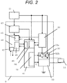
- FIG. 2 shows a circuit block diagram of a fuel-injection-system drive circuit.
- a fuel injection system is generally built in the ECU 9 shown in FIG. 1 .
- the voltage of a battery 41 is supplied to the ECU 9, and this voltage is supplied to a power source IC 43, a driver IC 47, a fuel-injection-system driving booster circuit 51, a high-side driver 52, etc.
- voltages are supplied by the power source IC 43 to a microcomputer 44, the driver IC 47, etc.
- the driver IC 47 has a communication unit 49 for the microcomputer 44, a booster-circuit driving unit 50, and a driver driving unit 48.
- a switching signal is transmitted from the booster-circuit driving unit 50 to the booster circuit 51, and the voltage increased by the booster circuit is supplied to a high-side driver 52. Meanwhile, the voltage increased by the booster circuit 51 is fed back to the booster-circuit driving unit 50, and whether a switching signal is to be transmitted again or not is determined by the driver IC 47. Meanwhile, the voltage increased by the booster circuit 51 can be fed back to an A/D converter 45 of the microcomputer 44, and, based on an A/D value, a signal can be transmitted from a communication unit 46 in the microcomputer 44 to the driver IC 47. Meanwhile, other than boost voltages, signals from a fuel pressure sensor, a temperature sensor, etc. can be input to and monitored by the A/D converter owned by the microcomputer 44.
- the microcomputer 44 has an input/output port 42, which drives an external load and/or monitors signals from outside.
- the high-side driver 52 can obtain power supplies from the booster circuit 51 and the battery 41 and has a driver 52a driven by the boost voltage and a driver 52b driven by the battery voltage. It has a role to cause a current to flow to a load 54, which has a coil, by drive signals (A, B) of the driver driving unit 48.
- a low-side driver 53 has a role to cause the current from the load 54, which has the coil, to flow to a ground electric potential by a drive signal (C) from the driver driving unit 48.
- either one of or both of the high-side driver 52 and the low-side driver 53 has a current detecting function and a terminal voltage detecting function using a shunt resistance, etc., wherein driver driving is carried out by detecting the values of the currents which flow to the driver and the load 54 and feeding back the current values. Meanwhile, by these functions, overcurrent to the driver, power-source short circuit and ground short circuit of terminals can be also detected.
- the booster circuit 51, the high-side driver 52, and the low-side driver 53 may be provided inside or outside the driver IC 47, and the driver IC 47 may be used as either role as a driver or a pre-driver.
- FIG. 3 is a diagram describing details of the booster circuit 51.
- a gate voltage Vg of a booster driver 63 When a gate voltage Vg of a booster driver 63 is turned on, a current I flows from the battery 41 to GND via a shunt resistance 61, a booster coil 62, and the booster driver 63. The current at this point is detected as a both-end voltage of the shunt resistance 61 by the booster-circuit driving unit 50.
- the booster driver 63 is turned off. At that point, the current I flows to a booster diode 64 because of back electromotive force of the booster coil 62.
- a booster capacitor 65 functions to temporarily store the current, which has flowed to the diode.
- the booster driver 63 is turned on again, and the current value is increased. By repeating this, the current is kept flowing to the booster diode 64 and storing the current in the booster capacitor 65, thereby generating a boost voltage.
- a circuit 66 which monitors the boost voltage is provided in the booster circuit; wherein, voltage boosting is carried out when the voltage is low, and the boost voltage is monitored in order to stop voltage boosting when the voltage reaches a predetermined value.
- the waveforms of a voltage boosting operation are shown by a diagram in FIG. 4 .
- the gate signal for turning on the booster driver 63 is Vg.
- a drain voltage Vd of the booster driver 63 is reduced to the vicinity of 0 V, and the current I is increased.
- the gate signal Vg of the booster driver 63 is turned off.
- Vd reaches a voltage equivalent to the boost voltage
- the current I flows to the booster diode 64 side and is stored in the booster capacitor 65; however, the current value per se is reduced along with time. Since the booster driver 63 is turned on again when the current reaches a set Min current, the operation of FIG. 4 is carried out by repeating this operation. This operation is carried out until the boost voltage reaches a set value.
- hatched parts in the diagram represent the currents which actually flow through the booster diode 64 and represent the currents which are used in boosting.
- the booster circuit has a waveform like that of the boost voltage of FIG. 4 .
- Vg is off, the current flows to the booster capacitor, and the boost voltage is therefore increased.
- Vg is on, the current does not enter the booster capacitor, and the boost voltage is therefore not increased (is slightly reduced since natural discharge is carried out).
- Voltage boosting is carried out by Vg switching until the boost voltage becomes a predetermined value as a result of the repetition thereof.
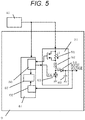
- FIG. 5 and FIG. 6 are diagrams described as embodiments of claims 1 to 3 of the present invention.
- FIG. 5 is a diagram in which a determination unit 67 for read boost signals and boost voltages is provided with respect to FIG. 3 .
- the determination unit 67 is provided inside or outside the driver IC 47 and is a part which monitors and diagnoses differences in the boost voltage and on/off drive of the booster circuit two times at measurement points.
- FIG. 6 a boost voltage waveform of a case in which the capacity of the booster capacitor 65 has been reduced is added to FIG. 4 (broken line in the diagram).
- a boost-voltage restoring operation is started; wherein, the voltage Vb of a point immediately before the booster driver 63 is turned off in order to check the voltage value increased by one time of switching and a voltage Vc at a point it is turned on are monitored.
- the difference is increased if the capacity is reduced due to deterioration or a broken wire of the booster capacitor 65 (normal case (2) ⁇ capacity reduced case (2)').
- diagnosis is carried out.
- FIG. 7 and FIG. 8 are flow charts of the contents of the description in FIG. 6 .
- the boost voltage Va before fuel injection is monitored (101), and the boost voltage Vb at the point when the fuel injection current reaches the peak is monitored (102).
- the difference (1) is obtained (103). If the difference is equal to or less than a predetermined value V1, normal drive is carried out (104). If the difference is equal to or more than V1, diagnosis is carried out (105).
- the voltage Vb at the point immediately before the booster driver 63 is turned off (when Max current is detected) is monitored (201), and the voltage Vc at the point immediately before the booster driver 63 is turned on (when Min current is detected) is also monitored (202). Then, the difference (2) therebetween is obtained (203). If the difference is equal to or less than a predetermined value V2, normal drive is carried out (204). If the difference is equal to or more than V2, diagnosis is carried out (205).
- diagnosis can be carried out when there is a difference from a normal case.
- a diagnosis method by FIG. 7 or FIG. 8 distinguishment from deterioration and characteristic variations of other elements cannot be made in some cases. Therefore, when both of FIG. 7 and FIG. 8 are used, characteristic changes due to deterioration, broken wire, etc. of the booster capacitor 65 can be specified.
- a diagram thereof is shown in FIG. 9 , and this is the diagram described as embodiments of claims 1 and 4. Examples of characteristic changes include, other than the capacity value of the booster capacitor 65, the resistance value of the shunt resistance 61 for current monitoring, inductance of the booster coil 62, and the resistance value of an externally-connected fuel injection valve.
- the changes of the voltage (1) and voltage (2) in the cases in which the numerical values thereof become large or small are shown in the diagram.
- the change of the voltage (1) is larger than that in the normal operation and is larger than the threshold value V1 and if the change of the voltage (2) is larger than that in the normal operation and is larger than the threshold value V2, it can be distinguished as abnormality (deterioration, broken wire, etc.) of the booster capacitor 65.
- the change of the voltage (1) is not different from that in the normal operation, but the change of the voltage (2) is larger than that in the normal operation and is larger than the threshold value V2, the resistance value of the shunt resistance 61 has been reduced, or the inductance of the booster coil 62 has been increased.
- the system having a drive circuit configured to control electric power distribution to a coil driven to open/close a fuel injection valve, the range of decrease in the boost voltage when the fuel injection valve is opened and the range of increase per 1 switching carried out for restoring the boost voltage are monitored.
Landscapes
- Engineering & Computer Science (AREA)
- Chemical & Material Sciences (AREA)
- Combustion & Propulsion (AREA)
- Mechanical Engineering (AREA)
- General Engineering & Computer Science (AREA)
- Electrical Control Of Air Or Fuel Supplied To Internal-Combustion Engine (AREA)
- Fuel-Injection Apparatus (AREA)
Claims (4)
- Verstärkerschaltung (51), die in einer Ansteuerschaltung verwendet wird, die konfiguriert ist, die Verteilung elektrischer Leistung zu einer Spule, die konfiguriert ist, angesteuert zu werden, um ein Kraftstoffeinspritzventil (5) zu öffnen/schließen, zu steuern, wobei die Verstärkerschaltung (51) Folgendes umfasst:- ein Verstärkungsschaltelement (63), das konfiguriert ist, eine Verstärkungsspannung zu erzeugen, die höher als eine Batteriespannung ist;- eine Spule (62);- eine Stromüberwachungsschaltung (66);- eine Diode (64) und- eine Verstärkerkondensator (65), der konfiguriert ist, die Verstärkungsspannung zu speichern; wobeidie Verstärkerschaltung (51) konfiguriert ist, eine charakteristische Änderung oder einen Fehler jedes des Verstärkerkondensators, der Stromüberwachungsschaltung (66) oder der Spule (62) und eines extern verbundenen Kraftstoffeinspritzventils (5) durch Überwachen sowohl eines Bereichs einer Abnahme der Verstärkungsspannung beim Kraftstoffeinspritzen als auch eines Bereichs der Zunahme der Spannung pro 1 Schalten bei der Verstärkungsspannungswiederherstellung zu unterscheiden.
- Verstärkerschaltung (51), wobei dann, wenn der Fehler nach Anspruch 1 eine Änderung sowohl des Bereichs der Abnahme der Verstärkungsspannung als auch des Bereichs der Zunahme der Spannung pro 1 Schalten der Verstärkerschaltung (51) umfasst, der Fehler als Alterung oder gebrochener Draht des Verstärkerkondensators unterschieden wird.
- Verstärkerschaltung (51), wobei dann, wenn der Fehler nach Anspruch 1 keine Änderung des Bereichs der Abnahme der Verstärkungsspannung umfasst, jedoch die Änderung des Bereichs der Zunahme der Spannung pro 1 Schalten der Verstärkerschaltung (51) umfasst, der Fehler als eine Änderung oder Fehlfunktion eines Widerstandswerts der Verstärkungsstromüberwachungsschaltung (66) oder der Induktivität der Spule (62) unterschieden wird.
- Verstärkerschaltung (51), wobei dann, wenn der Fehler nach Anspruch 1 die Änderung des Bereichs der Abnahme der Verstärkungsspannung umfasst und keine Änderung des Bereichs der Zunahme der Spannung pro 1 Schalten der Verstärkerschaltung (51) umfasst, der Fehler als Änderung oder Fehlfunktion eines Widerstandswerts eines Widerstandswerts des extern verbundenen Kraftstoffeinspritzventils (5) unterschieden wird.
Applications Claiming Priority (2)
| Application Number | Priority Date | Filing Date | Title |
|---|---|---|---|
| JP2014099208 | 2014-05-13 | ||
| PCT/JP2015/063163 WO2015174310A1 (ja) | 2014-05-13 | 2015-05-07 | 内燃機関の燃料噴射装置 |
Publications (3)
| Publication Number | Publication Date |
|---|---|
| EP3144512A1 EP3144512A1 (de) | 2017-03-22 |
| EP3144512A4 EP3144512A4 (de) | 2018-01-17 |
| EP3144512B1 true EP3144512B1 (de) | 2019-07-10 |
Family
ID=54479851
Family Applications (1)
| Application Number | Title | Priority Date | Filing Date |
|---|---|---|---|
| EP15792776.5A Active EP3144512B1 (de) | 2014-05-13 | 2015-05-07 | Brennstoffeinspritzsystem für verbrennungsmotoren |
Country Status (5)
| Country | Link |
|---|---|
| US (1) | US10267253B2 (de) |
| EP (1) | EP3144512B1 (de) |
| JP (1) | JP6181865B2 (de) |
| CN (1) | CN106460703B (de) |
| WO (1) | WO2015174310A1 (de) |
Families Citing this family (10)
| Publication number | Priority date | Publication date | Assignee | Title |
|---|---|---|---|---|
| US10669964B2 (en) | 2014-08-25 | 2020-06-02 | Hitachi Automotive Systems, Ltd. | Diagnosis of boost capacitor using discharge circuit |
| US10428759B2 (en) * | 2014-12-08 | 2019-10-01 | Hitachi Automotive Systems, Ltd. | Fuel control device for internal combustion engine |
| JP6393346B2 (ja) * | 2015-02-05 | 2018-09-19 | 日立オートモティブシステムズ株式会社 | 内燃機関の制御装置 |
| DE102016223564A1 (de) * | 2015-11-30 | 2017-06-01 | Robert Bosch Engineering and Business Solutions Ltd. | Ansteurungs- und steuerungsmodul für einen injektor und betriebsverfahren dafür |
| JP6466025B2 (ja) * | 2016-03-30 | 2019-02-06 | 日立オートモティブシステムズ株式会社 | 制御回路 |
| JP2018096229A (ja) * | 2016-12-09 | 2018-06-21 | 株式会社デンソー | 噴射制御装置 |
| JP6972844B2 (ja) * | 2017-09-27 | 2021-11-24 | 株式会社デンソー | インジェクタ駆動装置 |
| DE112019000244T5 (de) * | 2018-02-26 | 2020-08-20 | Hitachi Automotive Systems, Ltd. | Kraftstoffeinspritz-steuervorrichtung und kraftstoffeinspritz-steuerverfahren |
| JP6987035B2 (ja) * | 2018-09-27 | 2021-12-22 | 日立Astemo株式会社 | 電磁弁駆動装置 |
| JP7318594B2 (ja) * | 2020-06-29 | 2023-08-01 | 株式会社デンソー | 噴射制御装置 |
Family Cites Families (36)
| Publication number | Priority date | Publication date | Assignee | Title |
|---|---|---|---|---|
| US4486703A (en) * | 1982-09-27 | 1984-12-04 | The Bendix Corporation | Boost voltage generator |
| US4479161A (en) * | 1982-09-27 | 1984-10-23 | The Bendix Corporation | Switching type driver circuit for fuel injector |
| US4774624A (en) * | 1987-07-06 | 1988-09-27 | Motorola, Inc. | Boost voltage power supply for vehicle control system |
| JP2767317B2 (ja) * | 1990-10-15 | 1998-06-18 | 株式会社ユニシアジェックス | 燃料噴射弁駆動回路の断線診断装置 |
| IT1261580B (it) | 1993-09-07 | 1996-05-23 | Fiat Ricerche | Metodo di diagnosi di guasti di iniettori di impianti di iniezione ad alta pressione per motori a combustione interna |
| JP3635751B2 (ja) | 1995-11-30 | 2005-04-06 | 株式会社デンソー | 電磁弁駆動装置 |
| DE19903555C2 (de) * | 1999-01-29 | 2001-05-31 | Daimler Chrysler Ag | Vorrichtung zur Steuerung eines Piezoelement-Einspritzventils |
| DE19957181A1 (de) * | 1999-11-27 | 2001-05-31 | Bosch Gmbh Robert | Verfahren und Vorrichtung zur Ansteuerung wenigstens eines Verbrauchers |
| DE60031092D1 (de) * | 2000-04-01 | 2006-11-16 | Bosch Gmbh Robert | Kraftstoffeinspritzsystem |
| DE10028353C2 (de) * | 2000-06-08 | 2003-02-20 | Siemens Ag | Verfahren zur Überprüfung eines kapazitiven Stellgliedes |
| DE10033196A1 (de) * | 2000-07-07 | 2002-01-17 | Bosch Gmbh Robert | Verfahren bzw. Vorrichtungzur Erkennung eines Fehlerstromes an einem piezoelektrischen Aktor eines Einspritzventils oder an dessen Hochspannung führende Zuleitung |
| JP3699370B2 (ja) * | 2001-07-13 | 2005-09-28 | 三菱電機株式会社 | 燃料噴射装置の故障検出回路 |
| JP2004044429A (ja) * | 2002-07-10 | 2004-02-12 | Hitachi Ltd | 自動車用インジェクタ駆動装置の保護回路 |
| JP3894088B2 (ja) * | 2002-10-07 | 2007-03-14 | 株式会社日立製作所 | 燃料供給装置 |
| US7252072B2 (en) * | 2003-03-12 | 2007-08-07 | Cummins Inc. | Methods and systems of diagnosing fuel injection system error |
| JP4604959B2 (ja) * | 2005-10-24 | 2011-01-05 | 株式会社デンソー | 燃料噴射制御装置 |
| JP4539573B2 (ja) * | 2006-02-01 | 2010-09-08 | 株式会社デンソー | 燃料噴射制御装置 |
| EP2428670B1 (de) * | 2006-04-03 | 2021-06-09 | Delphi Technologies IP Limited | Treiberschaltung für eine Einspritzventilanordnung |
| JP4474423B2 (ja) * | 2007-01-12 | 2010-06-02 | 日立オートモティブシステムズ株式会社 | 内燃機関制御装置 |
| EP2006518B1 (de) * | 2007-06-22 | 2011-11-02 | Delphi Technologies Holding S.à.r.l. | Fehlerdetektion in einer Injektoranordnung |
| JP4375487B2 (ja) * | 2007-08-31 | 2009-12-02 | 株式会社デンソー | 燃料噴射装置及び燃料噴射システム |
| DE102007042994A1 (de) * | 2007-09-10 | 2009-03-12 | Robert Bosch Gmbh | Verfahren zum Beurteilen einer Funktionsweise eines Einspritzventils bei Anlegen einer Ansteuerspannung und entsprechende Auswertevorrichtung |
| EP2048343A1 (de) * | 2007-10-11 | 2009-04-15 | Delphi Technologies, Inc. | Fehlererkennung in einer Injektoranordnung |
| JP4926032B2 (ja) * | 2007-12-25 | 2012-05-09 | 日立オートモティブシステムズ株式会社 | 内燃機関の制御装置 |
| JP4776651B2 (ja) * | 2008-03-28 | 2011-09-21 | 日立オートモティブシステムズ株式会社 | 内燃機関制御装置 |
| GB0807854D0 (en) * | 2008-04-30 | 2008-06-04 | Delphi Tech Inc | Detection of faults in an injector arrangement |
| US7856867B2 (en) * | 2009-02-06 | 2010-12-28 | Gm Global Technology Operations, Inc. | Injector control performance diagnostic systems |
| JP5300786B2 (ja) | 2010-05-27 | 2013-09-25 | 日立オートモティブシステムズ株式会社 | 内燃機関の燃料噴射弁駆動制御装置 |
| JP5392191B2 (ja) * | 2010-06-02 | 2014-01-22 | トヨタ自動車株式会社 | 車両の制御装置および制御方法 |
| US9901378B2 (en) * | 2011-07-29 | 2018-02-27 | Aesculap Ag | Surgical instrumentation for spinal surgery |
| JP5542884B2 (ja) * | 2012-08-30 | 2014-07-09 | 三菱電機株式会社 | 車載エンジン制御装置 |
| US9097225B2 (en) * | 2013-01-10 | 2015-08-04 | Continental Automotive Systems, Inc. | Method to detect partial failure of direct-injection boost voltage |
| WO2015045503A1 (ja) * | 2013-09-27 | 2015-04-02 | 日立オートモティブシステムズ株式会社 | 内燃機関の燃料噴射制御装置 |
| US10669964B2 (en) * | 2014-08-25 | 2020-06-02 | Hitachi Automotive Systems, Ltd. | Diagnosis of boost capacitor using discharge circuit |
| JP6310094B2 (ja) * | 2014-11-21 | 2018-04-11 | 本田技研工業株式会社 | 燃料噴射システムの制御装置 |
| US10428759B2 (en) * | 2014-12-08 | 2019-10-01 | Hitachi Automotive Systems, Ltd. | Fuel control device for internal combustion engine |
-
2015
- 2015-05-07 EP EP15792776.5A patent/EP3144512B1/de active Active
- 2015-05-07 CN CN201580024205.6A patent/CN106460703B/zh active Active
- 2015-05-07 US US15/309,958 patent/US10267253B2/en active Active
- 2015-05-07 JP JP2016519220A patent/JP6181865B2/ja active Active
- 2015-05-07 WO PCT/JP2015/063163 patent/WO2015174310A1/ja active Application Filing
Non-Patent Citations (1)
| Title |
|---|
| None * |
Also Published As
| Publication number | Publication date |
|---|---|
| US20170138289A1 (en) | 2017-05-18 |
| JPWO2015174310A1 (ja) | 2017-04-20 |
| CN106460703B (zh) | 2019-06-07 |
| EP3144512A1 (de) | 2017-03-22 |
| US10267253B2 (en) | 2019-04-23 |
| CN106460703A (zh) | 2017-02-22 |
| EP3144512A4 (de) | 2018-01-17 |
| JP6181865B2 (ja) | 2017-08-16 |
| WO2015174310A1 (ja) | 2015-11-19 |
Similar Documents
| Publication | Publication Date | Title |
|---|---|---|
| EP3144512B1 (de) | Brennstoffeinspritzsystem für verbrennungsmotoren | |
| US6880530B2 (en) | Fuel supply system | |
| US8436623B2 (en) | Electromagnetic load circuit failure diagnosis device | |
| JP5198496B2 (ja) | 内燃機関のエンジンコントロールユニット | |
| US7822537B2 (en) | Detection of faults in an injector arrangement | |
| US20060016435A1 (en) | Supplemental fuel injector trigger circuit | |
| EP2007000B1 (de) | Spannungsgenerator | |
| US20070285863A1 (en) | Driving circuit | |
| CN102177063B (zh) | 电动动力转向装置 | |
| JP2004347423A (ja) | 電気負荷の異常検出装置及び電子制御装置 | |
| US9353717B2 (en) | Engine control unit for driving an electric circuit and method | |
| US6845315B2 (en) | Engine air-intake control device and engine air-intake control method | |
| US6536415B2 (en) | Method and device for diagnosing the failure of a fuel delivery device in a fuel system | |
| US20080036465A1 (en) | Electric Circuit For Triggering A Piezoelectric Element, In Particular Of A Fuel Injection System Of A Motor Vehicle | |
| JP2001342881A (ja) | 燃料供給システムの異常検出装置 | |
| KR20110021809A (ko) | 부하 강하의 진단 방법 | |
| US6389901B1 (en) | Diagnostic method for a fuel supply system | |
| JP2012184686A (ja) | エンジンコントロールユニット | |
| US8733323B2 (en) | Method for ascertaining an error in a fuel metering unit of an injection system | |
| CN202300670U (zh) | 发动机控制单元 | |
| JP6158026B2 (ja) | 昇圧装置 | |
| JP2002246667A (ja) | ピエゾアクチュエータ駆動回路および燃料噴射装置 | |
| KR20130140369A (ko) | 연료펌프 모터 구동장치 및 구동방법 | |
| JP2018207189A (ja) | 電磁負荷駆動回路 |
Legal Events
| Date | Code | Title | Description |
|---|---|---|---|
| STAA | Information on the status of an ep patent application or granted ep patent |
Free format text: STATUS: THE INTERNATIONAL PUBLICATION HAS BEEN MADE |
|
| PUAI | Public reference made under article 153(3) epc to a published international application that has entered the european phase |
Free format text: ORIGINAL CODE: 0009012 |
|
| STAA | Information on the status of an ep patent application or granted ep patent |
Free format text: STATUS: REQUEST FOR EXAMINATION WAS MADE |
|
| 17P | Request for examination filed |
Effective date: 20161213 |
|
| AK | Designated contracting states |
Kind code of ref document: A1 Designated state(s): AL AT BE BG CH CY CZ DE DK EE ES FI FR GB GR HR HU IE IS IT LI LT LU LV MC MK MT NL NO PL PT RO RS SE SI SK SM TR |
|
| AX | Request for extension of the european patent |
Extension state: BA ME |
|
| DAV | Request for validation of the european patent (deleted) | ||
| DAX | Request for extension of the european patent (deleted) | ||
| A4 | Supplementary search report drawn up and despatched |
Effective date: 20171215 |
|
| RIC1 | Information provided on ipc code assigned before grant |
Ipc: F02D 41/32 20060101ALI20171208BHEP Ipc: F02D 41/20 20060101ALN20171208BHEP Ipc: F02D 41/22 20060101AFI20171208BHEP Ipc: F02D 45/00 20060101ALI20171208BHEP |
|
| GRAP | Despatch of communication of intention to grant a patent |
Free format text: ORIGINAL CODE: EPIDOSNIGR1 |
|
| RIC1 | Information provided on ipc code assigned before grant |
Ipc: F02D 41/22 20060101AFI20181214BHEP Ipc: F02D 41/20 20060101ALN20181214BHEP Ipc: F02D 45/00 20060101ALI20181214BHEP Ipc: F02D 41/32 20060101ALI20181214BHEP |
|
| STAA | Information on the status of an ep patent application or granted ep patent |
Free format text: STATUS: GRANT OF PATENT IS INTENDED |
|
| INTG | Intention to grant announced |
Effective date: 20190124 |
|
| GRAS | Grant fee paid |
Free format text: ORIGINAL CODE: EPIDOSNIGR3 |
|
| GRAA | (expected) grant |
Free format text: ORIGINAL CODE: 0009210 |
|
| STAA | Information on the status of an ep patent application or granted ep patent |
Free format text: STATUS: THE PATENT HAS BEEN GRANTED |
|
| AK | Designated contracting states |
Kind code of ref document: B1 Designated state(s): AL AT BE BG CH CY CZ DE DK EE ES FI FR GB GR HR HU IE IS IT LI LT LU LV MC MK MT NL NO PL PT RO RS SE SI SK SM TR |
|
| REG | Reference to a national code |
Ref country code: GB Ref legal event code: FG4D |
|
| REG | Reference to a national code |
Ref country code: CH Ref legal event code: EP Ref country code: AT Ref legal event code: REF Ref document number: 1153817 Country of ref document: AT Kind code of ref document: T Effective date: 20190715 |
|
| REG | Reference to a national code |
Ref country code: DE Ref legal event code: R096 Ref document number: 602015033614 Country of ref document: DE |
|
| REG | Reference to a national code |
Ref country code: IE Ref legal event code: FG4D |
|
| REG | Reference to a national code |
Ref country code: NL Ref legal event code: MP Effective date: 20190710 |
|
| REG | Reference to a national code |
Ref country code: LT Ref legal event code: MG4D |
|
| REG | Reference to a national code |
Ref country code: AT Ref legal event code: MK05 Ref document number: 1153817 Country of ref document: AT Kind code of ref document: T Effective date: 20190710 |
|
| PG25 | Lapsed in a contracting state [announced via postgrant information from national office to epo] |
Ref country code: FI Free format text: LAPSE BECAUSE OF FAILURE TO SUBMIT A TRANSLATION OF THE DESCRIPTION OR TO PAY THE FEE WITHIN THE PRESCRIBED TIME-LIMIT Effective date: 20190710 Ref country code: AT Free format text: LAPSE BECAUSE OF FAILURE TO SUBMIT A TRANSLATION OF THE DESCRIPTION OR TO PAY THE FEE WITHIN THE PRESCRIBED TIME-LIMIT Effective date: 20190710 Ref country code: NO Free format text: LAPSE BECAUSE OF FAILURE TO SUBMIT A TRANSLATION OF THE DESCRIPTION OR TO PAY THE FEE WITHIN THE PRESCRIBED TIME-LIMIT Effective date: 20191010 Ref country code: SE Free format text: LAPSE BECAUSE OF FAILURE TO SUBMIT A TRANSLATION OF THE DESCRIPTION OR TO PAY THE FEE WITHIN THE PRESCRIBED TIME-LIMIT Effective date: 20190710 Ref country code: NL Free format text: LAPSE BECAUSE OF FAILURE TO SUBMIT A TRANSLATION OF THE DESCRIPTION OR TO PAY THE FEE WITHIN THE PRESCRIBED TIME-LIMIT Effective date: 20190710 Ref country code: BG Free format text: LAPSE BECAUSE OF FAILURE TO SUBMIT A TRANSLATION OF THE DESCRIPTION OR TO PAY THE FEE WITHIN THE PRESCRIBED TIME-LIMIT Effective date: 20191010 Ref country code: PT Free format text: LAPSE BECAUSE OF FAILURE TO SUBMIT A TRANSLATION OF THE DESCRIPTION OR TO PAY THE FEE WITHIN THE PRESCRIBED TIME-LIMIT Effective date: 20191111 Ref country code: LT Free format text: LAPSE BECAUSE OF FAILURE TO SUBMIT A TRANSLATION OF THE DESCRIPTION OR TO PAY THE FEE WITHIN THE PRESCRIBED TIME-LIMIT Effective date: 20190710 Ref country code: HR Free format text: LAPSE BECAUSE OF FAILURE TO SUBMIT A TRANSLATION OF THE DESCRIPTION OR TO PAY THE FEE WITHIN THE PRESCRIBED TIME-LIMIT Effective date: 20190710 |
|
| PG25 | Lapsed in a contracting state [announced via postgrant information from national office to epo] |
Ref country code: IS Free format text: LAPSE BECAUSE OF FAILURE TO SUBMIT A TRANSLATION OF THE DESCRIPTION OR TO PAY THE FEE WITHIN THE PRESCRIBED TIME-LIMIT Effective date: 20191110 Ref country code: RS Free format text: LAPSE BECAUSE OF FAILURE TO SUBMIT A TRANSLATION OF THE DESCRIPTION OR TO PAY THE FEE WITHIN THE PRESCRIBED TIME-LIMIT Effective date: 20190710 Ref country code: GR Free format text: LAPSE BECAUSE OF FAILURE TO SUBMIT A TRANSLATION OF THE DESCRIPTION OR TO PAY THE FEE WITHIN THE PRESCRIBED TIME-LIMIT Effective date: 20191011 Ref country code: AL Free format text: LAPSE BECAUSE OF FAILURE TO SUBMIT A TRANSLATION OF THE DESCRIPTION OR TO PAY THE FEE WITHIN THE PRESCRIBED TIME-LIMIT Effective date: 20190710 Ref country code: LV Free format text: LAPSE BECAUSE OF FAILURE TO SUBMIT A TRANSLATION OF THE DESCRIPTION OR TO PAY THE FEE WITHIN THE PRESCRIBED TIME-LIMIT Effective date: 20190710 Ref country code: ES Free format text: LAPSE BECAUSE OF FAILURE TO SUBMIT A TRANSLATION OF THE DESCRIPTION OR TO PAY THE FEE WITHIN THE PRESCRIBED TIME-LIMIT Effective date: 20190710 |
|
| PG25 | Lapsed in a contracting state [announced via postgrant information from national office to epo] |
Ref country code: TR Free format text: LAPSE BECAUSE OF FAILURE TO SUBMIT A TRANSLATION OF THE DESCRIPTION OR TO PAY THE FEE WITHIN THE PRESCRIBED TIME-LIMIT Effective date: 20190710 |
|
| PG25 | Lapsed in a contracting state [announced via postgrant information from national office to epo] |
Ref country code: IT Free format text: LAPSE BECAUSE OF FAILURE TO SUBMIT A TRANSLATION OF THE DESCRIPTION OR TO PAY THE FEE WITHIN THE PRESCRIBED TIME-LIMIT Effective date: 20190710 Ref country code: RO Free format text: LAPSE BECAUSE OF FAILURE TO SUBMIT A TRANSLATION OF THE DESCRIPTION OR TO PAY THE FEE WITHIN THE PRESCRIBED TIME-LIMIT Effective date: 20190710 Ref country code: PL Free format text: LAPSE BECAUSE OF FAILURE TO SUBMIT A TRANSLATION OF THE DESCRIPTION OR TO PAY THE FEE WITHIN THE PRESCRIBED TIME-LIMIT Effective date: 20190710 Ref country code: EE Free format text: LAPSE BECAUSE OF FAILURE TO SUBMIT A TRANSLATION OF THE DESCRIPTION OR TO PAY THE FEE WITHIN THE PRESCRIBED TIME-LIMIT Effective date: 20190710 Ref country code: DK Free format text: LAPSE BECAUSE OF FAILURE TO SUBMIT A TRANSLATION OF THE DESCRIPTION OR TO PAY THE FEE WITHIN THE PRESCRIBED TIME-LIMIT Effective date: 20190710 |
|
| PG25 | Lapsed in a contracting state [announced via postgrant information from national office to epo] |
Ref country code: SK Free format text: LAPSE BECAUSE OF FAILURE TO SUBMIT A TRANSLATION OF THE DESCRIPTION OR TO PAY THE FEE WITHIN THE PRESCRIBED TIME-LIMIT Effective date: 20190710 Ref country code: CZ Free format text: LAPSE BECAUSE OF FAILURE TO SUBMIT A TRANSLATION OF THE DESCRIPTION OR TO PAY THE FEE WITHIN THE PRESCRIBED TIME-LIMIT Effective date: 20190710 Ref country code: SM Free format text: LAPSE BECAUSE OF FAILURE TO SUBMIT A TRANSLATION OF THE DESCRIPTION OR TO PAY THE FEE WITHIN THE PRESCRIBED TIME-LIMIT Effective date: 20190710 Ref country code: IS Free format text: LAPSE BECAUSE OF FAILURE TO SUBMIT A TRANSLATION OF THE DESCRIPTION OR TO PAY THE FEE WITHIN THE PRESCRIBED TIME-LIMIT Effective date: 20200224 |
|
| REG | Reference to a national code |
Ref country code: DE Ref legal event code: R097 Ref document number: 602015033614 Country of ref document: DE |
|
| PLBE | No opposition filed within time limit |
Free format text: ORIGINAL CODE: 0009261 |
|
| STAA | Information on the status of an ep patent application or granted ep patent |
Free format text: STATUS: NO OPPOSITION FILED WITHIN TIME LIMIT |
|
| PG2D | Information on lapse in contracting state deleted |
Ref country code: IS |
|
| 26N | No opposition filed |
Effective date: 20200603 |
|
| PG25 | Lapsed in a contracting state [announced via postgrant information from national office to epo] |
Ref country code: SI Free format text: LAPSE BECAUSE OF FAILURE TO SUBMIT A TRANSLATION OF THE DESCRIPTION OR TO PAY THE FEE WITHIN THE PRESCRIBED TIME-LIMIT Effective date: 20190710 |
|
| PG25 | Lapsed in a contracting state [announced via postgrant information from national office to epo] |
Ref country code: MC Free format text: LAPSE BECAUSE OF FAILURE TO SUBMIT A TRANSLATION OF THE DESCRIPTION OR TO PAY THE FEE WITHIN THE PRESCRIBED TIME-LIMIT Effective date: 20190710 Ref country code: LI Free format text: LAPSE BECAUSE OF NON-PAYMENT OF DUE FEES Effective date: 20200531 Ref country code: CH Free format text: LAPSE BECAUSE OF NON-PAYMENT OF DUE FEES Effective date: 20200531 |
|
| REG | Reference to a national code |
Ref country code: DE Ref legal event code: R082 Ref document number: 602015033614 Country of ref document: DE Representative=s name: MERH-IP MATIAS ERNY REICHL HOFFMANN PATENTANWA, DE Ref country code: BE Ref legal event code: MM Effective date: 20200531 Ref country code: DE Ref legal event code: R081 Ref document number: 602015033614 Country of ref document: DE Owner name: HITACHI ASTEMO, LTD., HITACHINAKA-SHI, JP Free format text: FORMER OWNER: HITACHI AUTOMOTIVE SYSTEMS, LTD., HITACHINAKA-SHI, IBARAKI, JP |
|
| PG25 | Lapsed in a contracting state [announced via postgrant information from national office to epo] |
Ref country code: LU Free format text: LAPSE BECAUSE OF NON-PAYMENT OF DUE FEES Effective date: 20200507 |
|
| PG25 | Lapsed in a contracting state [announced via postgrant information from national office to epo] |
Ref country code: IE Free format text: LAPSE BECAUSE OF NON-PAYMENT OF DUE FEES Effective date: 20200507 |
|
| PG25 | Lapsed in a contracting state [announced via postgrant information from national office to epo] |
Ref country code: BE Free format text: LAPSE BECAUSE OF NON-PAYMENT OF DUE FEES Effective date: 20200531 |
|
| PG25 | Lapsed in a contracting state [announced via postgrant information from national office to epo] |
Ref country code: MT Free format text: LAPSE BECAUSE OF FAILURE TO SUBMIT A TRANSLATION OF THE DESCRIPTION OR TO PAY THE FEE WITHIN THE PRESCRIBED TIME-LIMIT Effective date: 20190710 Ref country code: CY Free format text: LAPSE BECAUSE OF FAILURE TO SUBMIT A TRANSLATION OF THE DESCRIPTION OR TO PAY THE FEE WITHIN THE PRESCRIBED TIME-LIMIT Effective date: 20190710 |
|
| PG25 | Lapsed in a contracting state [announced via postgrant information from national office to epo] |
Ref country code: MK Free format text: LAPSE BECAUSE OF FAILURE TO SUBMIT A TRANSLATION OF THE DESCRIPTION OR TO PAY THE FEE WITHIN THE PRESCRIBED TIME-LIMIT Effective date: 20190710 |
|
| REG | Reference to a national code |
Ref country code: FR Ref legal event code: PLFP Year of fee payment: 9 |
|
| PGFP | Annual fee paid to national office [announced via postgrant information from national office to epo] |
Ref country code: DE Payment date: 20230331 Year of fee payment: 9 |
|
| PGFP | Annual fee paid to national office [announced via postgrant information from national office to epo] |
Ref country code: FR Payment date: 20240328 Year of fee payment: 10 |
|
| PGFP | Annual fee paid to national office [announced via postgrant information from national office to epo] |
Ref country code: GB Payment date: 20240402 Year of fee payment: 10 |