EP3135960B2 - Schalteinrichtung zur betätigung eines schaltgetriebes eines motorrads zur durchführung eines gangwechsels bei geschlossener kupplung - Google Patents
Schalteinrichtung zur betätigung eines schaltgetriebes eines motorrads zur durchführung eines gangwechsels bei geschlossener kupplung Download PDFInfo
- Publication number
- EP3135960B2 EP3135960B2 EP16183526.9A EP16183526A EP3135960B2 EP 3135960 B2 EP3135960 B2 EP 3135960B2 EP 16183526 A EP16183526 A EP 16183526A EP 3135960 B2 EP3135960 B2 EP 3135960B2
- Authority
- EP
- European Patent Office
- Prior art keywords
- shift
- motorcycle
- switching
- sensor
- drive motor
- Prior art date
- Legal status (The legal status is an assumption and is not a legal conclusion. Google has not performed a legal analysis and makes no representation as to the accuracy of the status listed.)
- Active
Links
Images

Classifications
-
- B—PERFORMING OPERATIONS; TRANSPORTING
- B62—LAND VEHICLES FOR TRAVELLING OTHERWISE THAN ON RAILS
- B62K—CYCLES; CYCLE FRAMES; CYCLE STEERING DEVICES; RIDER-OPERATED TERMINAL CONTROLS SPECIALLY ADAPTED FOR CYCLES; CYCLE AXLE SUSPENSIONS; CYCLE SIDE-CARS, FORECARS, OR THE LIKE
- B62K23/00—Rider-operated controls specially adapted for cycles, i.e. means for initiating control operations, e.g. levers, grips
- B62K23/08—Rider-operated controls specially adapted for cycles, i.e. means for initiating control operations, e.g. levers, grips foot actuated
-
- F—MECHANICAL ENGINEERING; LIGHTING; HEATING; WEAPONS; BLASTING
- F16—ENGINEERING ELEMENTS AND UNITS; GENERAL MEASURES FOR PRODUCING AND MAINTAINING EFFECTIVE FUNCTIONING OF MACHINES OR INSTALLATIONS; THERMAL INSULATION IN GENERAL
- F16H—GEARING
- F16H59/00—Control inputs to control units of change-speed- or reversing-gearings for conveying rotary motion
- F16H59/02—Selector apparatus
- F16H59/04—Ratio selector apparatus
- F16H59/044—Ratio selector apparatus consisting of electrical switches or sensors
-
- B—PERFORMING OPERATIONS; TRANSPORTING
- B60—VEHICLES IN GENERAL
- B60W—CONJOINT CONTROL OF VEHICLE SUB-UNITS OF DIFFERENT TYPE OR DIFFERENT FUNCTION; CONTROL SYSTEMS SPECIALLY ADAPTED FOR HYBRID VEHICLES; ROAD VEHICLE DRIVE CONTROL SYSTEMS FOR PURPOSES NOT RELATED TO THE CONTROL OF A PARTICULAR SUB-UNIT
- B60W30/00—Purposes of road vehicle drive control systems not related to the control of a particular sub-unit, e.g. of systems using conjoint control of vehicle sub-units
- B60W30/18—Propelling the vehicle
- B60W30/19—Improvement of gear change, e.g. by synchronisation or smoothing gear shift
-
- B—PERFORMING OPERATIONS; TRANSPORTING
- B62—LAND VEHICLES FOR TRAVELLING OTHERWISE THAN ON RAILS
- B62M—RIDER PROPULSION OF WHEELED VEHICLES OR SLEDGES; POWERED PROPULSION OF SLEDGES OR SINGLE-TRACK CYCLES; TRANSMISSIONS SPECIALLY ADAPTED FOR SUCH VEHICLES
- B62M25/00—Actuators for gearing speed-change mechanisms specially adapted for cycles
- B62M25/02—Actuators for gearing speed-change mechanisms specially adapted for cycles with mechanical transmitting systems, e.g. cables, levers
- B62M25/06—Actuators for gearing speed-change mechanisms specially adapted for cycles with mechanical transmitting systems, e.g. cables, levers foot actuated
-
- F—MECHANICAL ENGINEERING; LIGHTING; HEATING; WEAPONS; BLASTING
- F02—COMBUSTION ENGINES; HOT-GAS OR COMBUSTION-PRODUCT ENGINE PLANTS
- F02D—CONTROLLING COMBUSTION ENGINES
- F02D41/00—Electrical control of supply of combustible mixture or its constituents
- F02D41/02—Circuit arrangements for generating control signals
- F02D41/021—Introducing corrections for particular conditions exterior to the engine
- F02D41/0215—Introducing corrections for particular conditions exterior to the engine in relation with elements of the transmission
- F02D41/023—Introducing corrections for particular conditions exterior to the engine in relation with elements of the transmission in relation with the gear ratio shifting
-
- F—MECHANICAL ENGINEERING; LIGHTING; HEATING; WEAPONS; BLASTING
- F16—ENGINEERING ELEMENTS AND UNITS; GENERAL MEASURES FOR PRODUCING AND MAINTAINING EFFECTIVE FUNCTIONING OF MACHINES OR INSTALLATIONS; THERMAL INSULATION IN GENERAL
- F16H—GEARING
- F16H63/00—Control outputs from the control unit to change-speed- or reversing-gearings for conveying rotary motion or to other devices than the final output mechanism
- F16H63/40—Control outputs from the control unit to change-speed- or reversing-gearings for conveying rotary motion or to other devices than the final output mechanism comprising signals other than signals for actuating the final output mechanisms
- F16H63/50—Signals to an engine or motor
- F16H63/502—Signals to an engine or motor for smoothing gear shifts
-
- B—PERFORMING OPERATIONS; TRANSPORTING
- B60—VEHICLES IN GENERAL
- B60W—CONJOINT CONTROL OF VEHICLE SUB-UNITS OF DIFFERENT TYPE OR DIFFERENT FUNCTION; CONTROL SYSTEMS SPECIALLY ADAPTED FOR HYBRID VEHICLES; ROAD VEHICLE DRIVE CONTROL SYSTEMS FOR PURPOSES NOT RELATED TO THE CONTROL OF A PARTICULAR SUB-UNIT
- B60W2300/00—Indexing codes relating to the type of vehicle
- B60W2300/36—Cycles; Motorcycles; Scooters
-
- B—PERFORMING OPERATIONS; TRANSPORTING
- B60—VEHICLES IN GENERAL
- B60W—CONJOINT CONTROL OF VEHICLE SUB-UNITS OF DIFFERENT TYPE OR DIFFERENT FUNCTION; CONTROL SYSTEMS SPECIALLY ADAPTED FOR HYBRID VEHICLES; ROAD VEHICLE DRIVE CONTROL SYSTEMS FOR PURPOSES NOT RELATED TO THE CONTROL OF A PARTICULAR SUB-UNIT
- B60W2540/00—Input parameters relating to occupants
- B60W2540/16—Ratio selector position
- B60W2540/165—Rate of change
-
- B—PERFORMING OPERATIONS; TRANSPORTING
- B60—VEHICLES IN GENERAL
- B60W—CONJOINT CONTROL OF VEHICLE SUB-UNITS OF DIFFERENT TYPE OR DIFFERENT FUNCTION; CONTROL SYSTEMS SPECIALLY ADAPTED FOR HYBRID VEHICLES; ROAD VEHICLE DRIVE CONTROL SYSTEMS FOR PURPOSES NOT RELATED TO THE CONTROL OF A PARTICULAR SUB-UNIT
- B60W2710/00—Output or target parameters relating to a particular sub-units
- B60W2710/06—Combustion engines, Gas turbines
- B60W2710/0666—Engine torque
-
- B—PERFORMING OPERATIONS; TRANSPORTING
- B60—VEHICLES IN GENERAL
- B60Y—INDEXING SCHEME RELATING TO ASPECTS CROSS-CUTTING VEHICLE TECHNOLOGY
- B60Y2200/00—Type of vehicle
- B60Y2200/10—Road Vehicles
- B60Y2200/12—Motorcycles, Trikes; Quads; Scooters
-
- F—MECHANICAL ENGINEERING; LIGHTING; HEATING; WEAPONS; BLASTING
- F16—ENGINEERING ELEMENTS AND UNITS; GENERAL MEASURES FOR PRODUCING AND MAINTAINING EFFECTIVE FUNCTIONING OF MACHINES OR INSTALLATIONS; THERMAL INSULATION IN GENERAL
- F16H—GEARING
- F16H59/00—Control inputs to control units of change-speed- or reversing-gearings for conveying rotary motion
- F16H59/02—Selector apparatus
- F16H2059/0234—Selectors for gearings using foot control
-
- F—MECHANICAL ENGINEERING; LIGHTING; HEATING; WEAPONS; BLASTING
- F16—ENGINEERING ELEMENTS AND UNITS; GENERAL MEASURES FOR PRODUCING AND MAINTAINING EFFECTIVE FUNCTIONING OF MACHINES OR INSTALLATIONS; THERMAL INSULATION IN GENERAL
- F16H—GEARING
- F16H59/00—Control inputs to control units of change-speed- or reversing-gearings for conveying rotary motion
- F16H59/02—Selector apparatus
- F16H2059/0239—Up- and down-shift or range or mode selection by repeated movement
-
- F—MECHANICAL ENGINEERING; LIGHTING; HEATING; WEAPONS; BLASTING
- F16—ENGINEERING ELEMENTS AND UNITS; GENERAL MEASURES FOR PRODUCING AND MAINTAINING EFFECTIVE FUNCTIONING OF MACHINES OR INSTALLATIONS; THERMAL INSULATION IN GENERAL
- F16H—GEARING
- F16H59/00—Control inputs to control units of change-speed- or reversing-gearings for conveying rotary motion
- F16H59/02—Selector apparatus
- F16H2059/026—Details or special features of the selector casing or lever support
Definitions
- the present invention relates to a motorcycle with a switching device which operates the manual transmission of the motorcycle having a drive motor to carry out a gear change with the clutch between the drive motor and the manual transmission closed, the manual transmission having a rotatable shift shaft and a rotary shift drum, the switching device having a rotary actuation of the Shifting lever provided on the switching shaft and is designed to influence the output torque of the drive motor, the switching device having a first sensor device which detects the rotational actuation of the switching shaft.
- the gear change usually takes place in such a way that the driver of the motorcycle interrupts the torque transfer between the drive motor and the gearbox by opening the clutch and then operates the shift lever, which is coupled to the shift shaft, with his foot to shift up or down the driver then closes the clutch again by releasing the pulled clutch handle.
- shift assistants have the advantage that the period of time during which the output torque provided by the drive motor to accelerate the motorcycle is interrupted can be reduced, which is particularly advantageous for sports motorcycles or racing motorcycles.
- Changing gears without the driver having to operate the clutch is also of interest for touring drivers, as this can relieve the strain on the driver's clutch hand, especially when driving long distances, and this contributes to relaxed and comfortable driving.
- a motorcycle gearshift with a shift assistant for shifting without using the clutch has become known.
- the shift assistant known from this document has a spring storage unit, which experiences a change in preload when the shift lever is actuated, and switching to another gear is initiated and carried out by the energy stored in the spring.
- the shift assistant is placed concentrically on the gearshift shaft of the transmission and protrudes laterally from it.
- a movement of the shift lever is transmitted to the switch assistant and leads to a change in the spring preload of the spring storage unit.
- the energy stored in the spring is then used to support the gear changing process, with a sensor on the housing of the shift assistant being provided to detect the driver's desire to change gear, which detects the position of the shift lever, which in turn generates the increased spring preload when actuated accordingly by the driver the spring storage unit of the switching assistant is used.
- a switching device for motorcycles which has a switching force transmission device, which is arranged between the shift lever of the motorcycle and the shift shaft of the transmission and has two compression springs which are preloaded when a switching operation is to be carried out via a corresponding actuation of the shift lever.
- the two compression springs have different spring characteristics, which means that the detection of the spring travel covered when the shift lever is actuated leads to different spring forces.
- the spring force generated in each case is monitored by an electronic device and evaluated to determine whether a switching force threshold has been reached, whereby after the respective switching force threshold has been exceeded, the motor torque delivered by the drive motor is reduced and a switching process is carried out. Reaching the switching force threshold is therefore interpreted as a gear change request from the driver, whereupon the engine torque is reduced in order to be able to carry out the actual gear change.
- a switching device that is very similar to the switching device described above has become known, but instead of using two compression springs, it only works with one compression spring loaded in both switching directions and in which the driver's gear change request is determined by the preload force of the spring generated by the actuation of the shift lever is monitored for a switching force threshold, or the spring travel covered by the spring upon actuation of the switching lever is detected via a sensor device and converted into a switching force threshold, the exceeding of which is then interpreted as the driver's desire to change gear. If the switching force threshold is exceeded, the engine torque is reduced to carry out the actual gear change process.
- the spring leads to a switching behavior that is perceived by the driver of the motorcycle as indifferent or spongy; the spring makes it particularly difficult for the driver to find the idle speed, i.e. finding the neutral position of the motorcycle transmission.
- the switching assistants mentioned have a complex and therefore expensive structure and are prone to failure, as a spring can break at any time, whereupon the function of the switching assistant is no longer guaranteed and the vehicle equipped with it can no longer be used until an appropriate repair has been carried out.
- a spring is subject to fatigue and settling amounts, which change the switching behavior of a spring-equipped switching assistant over a longer period of operation, which the driver in turn has to adapt to.
- Shift assistance systems have also become known that work without a spring in the force transmission path between the shift lever and the shift shaft. These systems make use of a measurement of the force with which the rider of the motorcycle operates the gear lever (see the US 2008/115984 A1 ).
- the measured force value In order to trigger the gear change process by influencing the engine torque, the measured force value must exceed a set threshold value. If this threshold is set high, the driver has to operate the gearshift lever with high force in order to shift gears, which is tiring for the driver. If the threshold value is set low, even a short-term accidental touch of the gearshift lever by the driver will result in the threshold being exceeded and This leads to an unwanted switching process, which is an unpleasant surprise for the driver.
- Such switching assistance systems which usually work with pressure cells or strain gauges, are manufactured, for example, by Translogic Systems Ltd. offered. This description makes it clear that the driver must adapt to the triggering behavior of the shift assistance system.
- the present invention is based on the object of creating a motorcycle with a switching device for switching without clutch actuation, which enables the driver to use the motorcycle without having to adjust to a changed switching behavior.
- the invention creates a motorcycle with a switching device which operates the manual transmission of the motorcycle having a drive motor to carry out a gear change with the clutch closed between the drive motor and the manual transmission, the manual transmission having a rotatable shift shaft and a rotatable shift drum, the switching device having a rotary actuation of the shift shaft provided shift lever and is designed to influence the output torque of the drive motor, wherein the switching device has a first sensor device that detects the rotational actuation of the shift shaft, and the first sensor device is designed to directly detect the angle of rotation of the shift shaft that is set by the rotary actuation of the shift lever and to provide a first sensor signal is and the switching device is designed to influence the output torque of the drive motor as a function of the first sensor signal of the first sensor device, and the switching shaft is provided in the area of a front end section with a support bearing designed as a cylindrical body, which can be releasably secured to the switching shaft and has a receptacle for releasably fixing a
- the present invention it is provided to provide a first sensor device for detecting the rotational actuation of the switching shaft and to develop the switching device so that it influences the engine torque on the basis of the sensor signal of the first sensor device, i.e. the switching shaft angle sensor.
- the value of this force threshold can be higher than the value of the force that the driver habitually exerts for operating the transmission, which leads to an unusual change for the driver to actuating the shift lever in accordance with the force threshold. This disadvantage is avoided by the design of the switching device.
- the switching device has a second sensor device which detects the rotational actuation of the switching drum and the switching device is designed to influence the output torque of the drive motor as a function of a sensor signal from the second sensor device.
- a second sensor signal output by the second sensor device is available, which can be functionally coupled to the first sensor signal provided by the first sensor device in such a way that the engine torque output by the engine can be influenced by means of the switching device.
- This influence can be used, for example, so that the switching device reduces the engine torque to carry out the gear change process, which can be done on the basis of the first sensor signal provided by the first sensor device, and the switching device then reduces the engine torque again based on the second sensor signal provided by the second sensor device increased, for this purpose the rotational angle position of the shift drum is detected via the second sensor device and the rotational angle position is used to detect that the gear changing process has been completed and the engine torque can be increased again.
- the shift lever is positively coupled to the shift shaft for shifting force transmission to the shift shaft or is connected to the shift shaft with the interposition of a force transmission device.
- both configuration options are taken into account, namely that the shift lever is fixed to a front end of the shift shaft or, for example, is non-positively coupled to the front end of the shift shaft with a shift lever deflection.
- Spring device which is present in the known switching assistants, can be dispensed with.
- the switching device is therefore characterized by the advantage that an indifferent and spongy switching feeling generated by the spring device in the switching force transmission path can be avoided and, in particular, the idle detection is not impaired by such a spring device.
- the switching shaft is provided at a front end section with a support bearing designed as a cylindrical body, which can be releasably secured to the switching shaft and has a receptacle for releasably fixing a magnetic device.
- a support bearing designed as a cylindrical body, which can be releasably secured to the switching shaft and has a receptacle for releasably fixing a magnetic device.
- this body for example formed from a plastic material, functional integration is achieved, namely in that the body simultaneously serves as an axial bearing for mounting the switching shaft in the motor housing or transmission housing and has a receptacle for the arrangement of a permanent magnet in the receptacle, which is connected to the first sensor device arranged, for example, outside the motor housing or gearbox housing.
- the shift drum has in the region of a front end section in the recess in which a magnet device is arranged.
- the magnet device can be a permanent magnet, the angular position of which is detected by means of the second sensor device arranged outside the motor housing or the gearbox housing to provide the second sensor signal.
- the first and/or second sensor devices can be designed as non-contact Hall sensors, which work together with the magnet device arranged on the shift shaft or the magnet device arranged on the shift drum in order to detect the respective rotational angular position of the shift shaft and the shift drum and in this way the first and Provide second sensor signal.
- the switching device is designed to change gears of the manual transmission in both switching directions with the clutch closed and the gear stage engaged. In other words, this means that the switching device allows both upshifting to a higher gear and downshifting to a lower gear with the clutch closed, without the driver of the motorcycle having to operate the clutch.
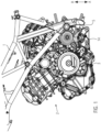
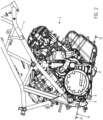
- FIG. 1 The drawing shows a side view of a representation with a motorcycle frame 1 and a drive motor 2 in the form of a V-engine.
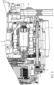
- the drive motor 2 has a gearbox 4 arranged in the motor housing 3, some components of which are in Fig. 3 can be seen in the drawing.
- the motorcycle not shown, has a shift lever 5, which is intended for actuating the gearbox 4 by the driver of the motorcycle.
- the driver can operate the shift lever 5 with his left foot, in the illustrated embodiment, in such a way that the driver moves the shift lever 5 in the direction of arrow A to downshift Fig. 1 as shown in the drawing and follow the direction of arrow B to shift up Fig. 1 .
- the rotational operation of the switching lever 5 leads to a rotational operation of the in Fig. 3
- the shift drum 7 shown in the drawing on the outer circumference of which link guides, not shown, are formed, which are in engagement with shift forks, also not shown, so that shift forks are axially displaced by a rotary actuation of the shift drum 7 by a predetermined rotation angle or pivot angle, which are axially displaceable , but can axially move gears mounted in a rotationally fixed manner on transmission shafts, which have switching claws on their side flanks and can thus produce the flow of power by engaging the switching claws or can interrupt the flow of power by releasing the engagement.
- the pivoting movement or actuation of the shift lever 5 by the driver of the motorcycle in any case leads to a rotational actuation of the shift shaft 6 by a specific rotation angle or pivot angle and to a rotational actuation of the shift drum 7 by a specific rotation angle or pivot angle.
- the driver's actuation of the shift lever leads to a rotational actuation of the shift shaft and the shift drum.
- the switching device for actuating the manual transmission 4 has an in Fig. 3
- the first sensor device, designated by reference number 8 in the drawing, is arranged on the outside of the motor housing 3 - as shown in FIG Fig. 2 can also be seen in the drawing - and in which the embodiment shown is a Hall sensor 9.
- Fig. 4 shows the Hall sensor 9 arranged on the outside of the motor housing 3 in such a way that the sensor 9 is arranged opposite a receptacle 10, which is formed on a cylindrical body 11 made of a plastic material, which at the same time serves as a support bearing 12A for the axial and radial guidance the switching shaft 6 is formed.
- a magnetic device in the form of a permanent magnet 12 is arranged in the receptacle 10, so that the angle of rotation or the pivoting angle of the switching shaft 6, which is set due to a rotational actuation of the switching lever 5 by the driver, can be detected by the Hall sensor 9 and is available as a first sensor signal Available.
- the first sensor device 8 which provides a sensor signal which comes from an electronic control device or regulating device (not shown).
- the switching device is detected and which then controls the drive motor 2 in such a way that the engine torque output by it is reduced and a gear changing process can then be carried out without the in Fig. 4
- the clutch 13 of the drive motor 2 shown in the drawing must be operated by the driver.
- the lever actuation force applied by the driver by operating the shift lever 5 in the manner known to him simultaneously provides the shifting force for the gear changing process, without him having to particularly adjust to the shifting device, i.e. changing his shifting behavior.
- This rotational operation of the shift drum 7 is carried out by an in Fig. 1 visible in the drawing and in Fig. 3
- the second sensor device 14 shown in more detail in the drawing is detected in the form of a Hall sensor 15, which can determine the change in the angle of rotation of the shift drum 7, namely via the interaction of the Hall sensor 15 with a permanent magnet 16 arranged at a front end of the shift drum 7.
- the rotary actuation of the switching drum 7 therefore leads to a change in the magnetic field built up by the permanent magnet 16, which is detected by the Hall sensor 15 and in this way provides a second sensor signal, which is also detected again by the control device or regulating device of the switching device, not shown in more detail and can be evaluated.
- This second sensor signal can also be used to influence the engine torque delivered by the drive motor 2, alone or in addition to the first sensor signal, in order to cancel the reduction in the engine torque or to increase the engine torque again.
- the switching device for switching the manual transmission without actuating the clutch of the motorcycle is characterized by the fact that, in contrast to known switching assistants, there is no spring device that can be changed by the driver's switching force in the power transmission path between the shift lever and the shift shaft and therefore the driver of the motorcycle also does not have to adjust to a switching behavior changed by such a spring.
- the actuation force applied by the driver to the shift lever to shift the gears of the transmission does not have to be recorded and evaluated and therefore a load cell or similar force detection device for detecting the actuation force does not have to be attached to the motorcycle.
- the driver's shift request can be detected and recognized via the rotary actuation of the shift shaft by means of the first sensor device working together with the shift shaft and the engine torque of the drive motor can then be reduced to carry out the gear change process, with the second sensor signal connected to the shift drum also being used to detect the shift request second sensor device working together can be evaluated.
- One or both sensor signals can then be used to correspondingly control the drive motor to reduce the drive torque to carry out the gear change process or to rebuild the drive torque.
- the switching device also has the advantage over the known switching assistants that the switching device is processed without wear, and the driver's usual low force of operating the shift lever is sufficient to initiate and carry out the gear changing process without operating the motorcycle's clutch, since with the on the Actuating force acting on the shift lever does not require a spring device to be clamped in the force transmission path between the shift lever and the shift shaft.
- the shift lever operation also has the feedback known to the driver of the motorcycle when the switching device is used, so the driver does not have to adjust to a changed switching behavior, since there is no torsion device or compression spring in the system, which creates a spongy and indifferent switching feeling.
Landscapes
- Engineering & Computer Science (AREA)
- Mechanical Engineering (AREA)
- General Engineering & Computer Science (AREA)
- Chemical & Material Sciences (AREA)
- Combustion & Propulsion (AREA)
- Transportation (AREA)
- Automation & Control Theory (AREA)
- Gear-Shifting Mechanisms (AREA)
- Control Of Transmission Device (AREA)
- Control Of Driving Devices And Active Controlling Of Vehicle (AREA)
- Control Of Vehicle Engines Or Engines For Specific Uses (AREA)
- Mechanical Control Devices (AREA)
Applications Claiming Priority (1)
| Application Number | Priority Date | Filing Date | Title |
|---|---|---|---|
| DE102015114338.0A DE102015114338A1 (de) | 2015-08-28 | 2015-08-28 | Schalteinrichtung zur Betätigung eines Schaltgetriebes eines Motorrads zur Durchführung eines Gangwechsels bei geschlossener Kupplung |
Publications (3)
| Publication Number | Publication Date |
|---|---|
| EP3135960A1 EP3135960A1 (de) | 2017-03-01 |
| EP3135960B1 EP3135960B1 (de) | 2020-05-06 |
| EP3135960B2 true EP3135960B2 (de) | 2023-09-20 |
Family
ID=56618064
Family Applications (1)
| Application Number | Title | Priority Date | Filing Date |
|---|---|---|---|
| EP16183526.9A Active EP3135960B2 (de) | 2015-08-28 | 2016-08-10 | Schalteinrichtung zur betätigung eines schaltgetriebes eines motorrads zur durchführung eines gangwechsels bei geschlossener kupplung |
Country Status (4)
| Country | Link |
|---|---|
| US (1) | US10598275B2 (enExample) |
| EP (1) | EP3135960B2 (enExample) |
| JP (2) | JP6678942B2 (enExample) |
| DE (1) | DE102015114338A1 (enExample) |
Families Citing this family (2)
| Publication number | Priority date | Publication date | Assignee | Title |
|---|---|---|---|---|
| DE102020123343A1 (de) | 2020-09-08 | 2022-03-10 | Bayerische Motoren Werke Aktiengesellschaft | Verfahren und Vorrichtung zur Überprüfung der Stellung des Schalthebels eines Getriebes eines Fahrzeugs |
| EP4675133A1 (en) * | 2024-07-01 | 2026-01-07 | Ducati Motor Holding S.p.A. | Method and device for quickly shifting the gear of the engine of a motorcycle |
Citations (1)
| Publication number | Priority date | Publication date | Assignee | Title |
|---|---|---|---|---|
| WO2015114109A1 (de) † | 2014-01-31 | 2015-08-06 | Hs Products Engineering Gmbh | Kraftübertragungsvorrichtung für ein getriebe |
Family Cites Families (21)
| Publication number | Priority date | Publication date | Assignee | Title |
|---|---|---|---|---|
| DE2742809A1 (de) | 1977-09-23 | 1979-04-05 | Sachs Systemtechnik Gmbh | Einrichtung zur erleichterung eines schnellen gangwechsels bei kraftfahrzeug-getrieben |
| DE2941556A1 (de) | 1977-09-23 | 1981-04-23 | Sachs Systemtechnik Gmbh, 8720 Schweinfurt | Einrichtung zur erleichterung eines schnellen gangwechsels |
| JPH05302531A (ja) | 1992-04-24 | 1993-11-16 | Yamaha Motor Co Ltd | 自動二輪車の変速制御装置 |
| DE29812605U1 (de) | 1998-07-15 | 1998-09-17 | Scheffler, Burkhard, 28719 Bremen | Schaltvorrichtung für ein Motorradgetriebe |
| US6426619B1 (en) | 1998-12-09 | 2002-07-30 | Cts Corporation | Pedal with integrated position sensor |
| JP2001140668A (ja) * | 1999-11-12 | 2001-05-22 | Yamaha Motor Co Ltd | 自動二輪車の変速制御装置 |
| DE102005017237B4 (de) * | 2005-04-14 | 2014-03-20 | Rudy Tellert | Vorrichtung und Verfahren zum Wechseln von Gangstufen in Getrieben von Kraftfahrzeugen |
| JP4516485B2 (ja) | 2005-06-14 | 2010-08-04 | 本田技研工業株式会社 | 自動二輪車用変速装置、自動二輪車及び自動二輪車のシミュレーション装置 |
| JP4767149B2 (ja) * | 2006-10-27 | 2011-09-07 | ヤマハ発動機株式会社 | 鞍乗型車両 |
| JP2008144756A (ja) * | 2006-11-16 | 2008-06-26 | Yamaha Motor Co Ltd | 制御システムおよびそれを備えた車両 |
| JP4762182B2 (ja) * | 2007-03-20 | 2011-08-31 | 川崎重工業株式会社 | 車両の変速制御装置及びそれを備える車両 |
| ITBG20080013U1 (it) | 2008-06-30 | 2009-12-30 | Starlane S R L | Cambio semiautomatico per veicoli con cambio avente asta di rinvio. |
| JP5238464B2 (ja) * | 2008-11-21 | 2013-07-17 | ヤマハ発動機株式会社 | 制御システムおよびそれを備えた鞍乗り型車両 |
| JP5190395B2 (ja) | 2009-02-26 | 2013-04-24 | 本田技研工業株式会社 | 鞍乗型車両の変速制御装置 |
| DE102010015037B4 (de) | 2010-04-15 | 2020-07-02 | Bayerische Motoren Werke Aktiengesellschaft | Schalteinrichtung für Motorräder |
| DE102010015036B4 (de) | 2010-04-15 | 2018-11-22 | Bayerische Motoren Werke Aktiengesellschaft | Schalteinrichtung für Motorräder |
| JP5613096B2 (ja) * | 2011-03-31 | 2014-10-22 | 本田技研工業株式会社 | シフトショック低減構造を備える車両 |
| DE102011086243A1 (de) | 2011-11-14 | 2013-05-16 | Robert Bosch Gmbh | Sensoreinheit für Schaltautomat |
| DE102012209720B4 (de) * | 2012-06-11 | 2017-09-14 | Bayerische Motoren Werke Aktiengesellschaft | Schalteinrichtung |
| DE102012209963A1 (de) | 2012-06-14 | 2013-12-19 | Robert Bosch Gmbh | Motorradschaltung mit Schaltassistent zum Schalten ohne Kupplungsbetätigung und Verfahren hierzu |
| JP2014190281A (ja) * | 2013-03-28 | 2014-10-06 | Honda Motor Co Ltd | 鞍乗型車両用アイドルストップ制御装置 |
-
2015
- 2015-08-28 DE DE102015114338.0A patent/DE102015114338A1/de not_active Ceased
-
2016
- 2016-08-10 EP EP16183526.9A patent/EP3135960B2/de active Active
- 2016-08-25 JP JP2016165101A patent/JP6678942B2/ja active Active
- 2016-08-25 US US15/247,684 patent/US10598275B2/en active Active
-
2018
- 2018-10-01 JP JP2018186810A patent/JP6660048B2/ja active Active
Patent Citations (1)
| Publication number | Priority date | Publication date | Assignee | Title |
|---|---|---|---|---|
| WO2015114109A1 (de) † | 2014-01-31 | 2015-08-06 | Hs Products Engineering Gmbh | Kraftübertragungsvorrichtung für ein getriebe |
Also Published As
| Publication number | Publication date |
|---|---|
| DE102015114338A1 (de) | 2017-03-02 |
| JP2019044971A (ja) | 2019-03-22 |
| JP2017044343A (ja) | 2017-03-02 |
| US10598275B2 (en) | 2020-03-24 |
| JP6660048B2 (ja) | 2020-03-04 |
| EP3135960A1 (de) | 2017-03-01 |
| JP6678942B2 (ja) | 2020-04-15 |
| US20170067555A1 (en) | 2017-03-09 |
| EP3135960B1 (de) | 2020-05-06 |
Similar Documents
| Publication | Publication Date | Title |
|---|---|---|
| DE19805383B4 (de) | Kraftfahrzeug-Lenkvorrichtung | |
| DE68925130T2 (de) | Servolenkung | |
| DE69809245T2 (de) | Automatisches toroidgetriebe für kraftfahrzeuge | |
| DE69806534T2 (de) | Steuerung für Servo-Schaltung | |
| DE60303081T2 (de) | Handradstellglied | |
| DE4404594C2 (de) | Bedien- und Steuereinrichtung | |
| DE19838146B4 (de) | Kraftübertragungsvorrichtung für ein Fahrzeug | |
| DE102004050486B4 (de) | System für die Erkennung der Endposition der Bewegung der Lenkung bei "Steer by Wire" Systemen | |
| DE68922248T2 (de) | Motorgetriebene Servolenkung. | |
| DE102014009517B3 (de) | Lenksystem | |
| DE102005058711B4 (de) | Fahrzeug-Steuer-/Regelvorrichtung | |
| DE19902556B4 (de) | Lenkgetrieb mit redundantem Antrieb | |
| EP2615022B1 (de) | Antriebsvorrichtung für ein Elektrofahrrad mit Kraftmessung zur Fahrerwunscherkennung | |
| DE10256694A1 (de) | Drahtlenkungs-Lenkvorrichtung mit betätigbarem Mechanismus | |
| DE3882142T2 (de) | Getriebe. | |
| DE102006048947A1 (de) | Steuereinheit und Verfahren zum Verstellen eines an ein Fahrzeug angekuppelten Anhängers | |
| EP1032522B1 (de) | Elektromotorischer stellantrieb für eine fahrzeuglenkanlage | |
| DE102018119977A1 (de) | Lenkgetriebe für ein Steer-by-Wire-Lenksystem | |
| EP3135960B2 (de) | Schalteinrichtung zur betätigung eines schaltgetriebes eines motorrads zur durchführung eines gangwechsels bei geschlossener kupplung | |
| DE10109814B4 (de) | Vorrichtung zum Konstanthalten der Fahrgeschwindigkeit eines Kraftrads | |
| DE69523075T2 (de) | Motorisch angetriebenes system zum lenken eines fahrzeugs | |
| WO2000055030A1 (de) | Vorrichtung zur lenkung eines fahrzeugs | |
| DE102014103789B4 (de) | Schaltvorrichtung für ein Getriebe | |
| DE3612619C2 (enExample) | ||
| DE102009058967A1 (de) | Fahrpedal |
Legal Events
| Date | Code | Title | Description |
|---|---|---|---|
| PUAI | Public reference made under article 153(3) epc to a published international application that has entered the european phase |
Free format text: ORIGINAL CODE: 0009012 |
|
| STAA | Information on the status of an ep patent application or granted ep patent |
Free format text: STATUS: THE APPLICATION HAS BEEN PUBLISHED |
|
| AK | Designated contracting states |
Kind code of ref document: A1 Designated state(s): AL AT BE BG CH CY CZ DE DK EE ES FI FR GB GR HR HU IE IS IT LI LT LU LV MC MK MT NL NO PL PT RO RS SE SI SK SM TR |
|
| AX | Request for extension of the european patent |
Extension state: BA ME |
|
| STAA | Information on the status of an ep patent application or granted ep patent |
Free format text: STATUS: REQUEST FOR EXAMINATION WAS MADE |
|
| 17P | Request for examination filed |
Effective date: 20170308 |
|
| RBV | Designated contracting states (corrected) |
Designated state(s): AL AT BE BG CH CY CZ DE DK EE ES FI FR GB GR HR HU IE IS IT LI LT LU LV MC MK MT NL NO PL PT RO RS SE SI SK SM TR |
|
| GRAP | Despatch of communication of intention to grant a patent |
Free format text: ORIGINAL CODE: EPIDOSNIGR1 |
|
| STAA | Information on the status of an ep patent application or granted ep patent |
Free format text: STATUS: GRANT OF PATENT IS INTENDED |
|
| RIC1 | Information provided on ipc code assigned before grant |
Ipc: B62M 25/06 20060101ALI20200121BHEP Ipc: B60K 23/08 20060101ALI20200121BHEP Ipc: B60W 30/19 20120101ALI20200121BHEP Ipc: F16H 63/50 20060101AFI20200121BHEP |
|
| INTG | Intention to grant announced |
Effective date: 20200226 |
|
| GRAS | Grant fee paid |
Free format text: ORIGINAL CODE: EPIDOSNIGR3 |
|
| GRAA | (expected) grant |
Free format text: ORIGINAL CODE: 0009210 |
|
| STAA | Information on the status of an ep patent application or granted ep patent |
Free format text: STATUS: THE PATENT HAS BEEN GRANTED |
|
| AK | Designated contracting states |
Kind code of ref document: B1 Designated state(s): AL AT BE BG CH CY CZ DE DK EE ES FI FR GB GR HR HU IE IS IT LI LT LU LV MC MK MT NL NO PL PT RO RS SE SI SK SM TR |
|
| REG | Reference to a national code |
Ref country code: GB Ref legal event code: FG4D Free format text: NOT ENGLISH |
|
| REG | Reference to a national code |
Ref country code: CH Ref legal event code: EP Ref country code: AT Ref legal event code: REF Ref document number: 1267270 Country of ref document: AT Kind code of ref document: T Effective date: 20200515 |
|
| REG | Reference to a national code |
Ref country code: IE Ref legal event code: FG4D Free format text: LANGUAGE OF EP DOCUMENT: GERMAN |
|
| REG | Reference to a national code |
Ref country code: DE Ref legal event code: R096 Ref document number: 502016009829 Country of ref document: DE |
|
| REG | Reference to a national code |
Ref country code: LT Ref legal event code: MG4D |
|
| REG | Reference to a national code |
Ref country code: NL Ref legal event code: MP Effective date: 20200506 |
|
| PG25 | Lapsed in a contracting state [announced via postgrant information from national office to epo] |
Ref country code: IS Free format text: LAPSE BECAUSE OF FAILURE TO SUBMIT A TRANSLATION OF THE DESCRIPTION OR TO PAY THE FEE WITHIN THE PRESCRIBED TIME-LIMIT Effective date: 20200906 Ref country code: FI Free format text: LAPSE BECAUSE OF FAILURE TO SUBMIT A TRANSLATION OF THE DESCRIPTION OR TO PAY THE FEE WITHIN THE PRESCRIBED TIME-LIMIT Effective date: 20200506 Ref country code: PT Free format text: LAPSE BECAUSE OF FAILURE TO SUBMIT A TRANSLATION OF THE DESCRIPTION OR TO PAY THE FEE WITHIN THE PRESCRIBED TIME-LIMIT Effective date: 20200907 Ref country code: LT Free format text: LAPSE BECAUSE OF FAILURE TO SUBMIT A TRANSLATION OF THE DESCRIPTION OR TO PAY THE FEE WITHIN THE PRESCRIBED TIME-LIMIT Effective date: 20200506 Ref country code: SE Free format text: LAPSE BECAUSE OF FAILURE TO SUBMIT A TRANSLATION OF THE DESCRIPTION OR TO PAY THE FEE WITHIN THE PRESCRIBED TIME-LIMIT Effective date: 20200506 Ref country code: NO Free format text: LAPSE BECAUSE OF FAILURE TO SUBMIT A TRANSLATION OF THE DESCRIPTION OR TO PAY THE FEE WITHIN THE PRESCRIBED TIME-LIMIT Effective date: 20200806 Ref country code: GR Free format text: LAPSE BECAUSE OF FAILURE TO SUBMIT A TRANSLATION OF THE DESCRIPTION OR TO PAY THE FEE WITHIN THE PRESCRIBED TIME-LIMIT Effective date: 20200807 |
|
| PG25 | Lapsed in a contracting state [announced via postgrant information from national office to epo] |
Ref country code: BG Free format text: LAPSE BECAUSE OF FAILURE TO SUBMIT A TRANSLATION OF THE DESCRIPTION OR TO PAY THE FEE WITHIN THE PRESCRIBED TIME-LIMIT Effective date: 20200806 Ref country code: RS Free format text: LAPSE BECAUSE OF FAILURE TO SUBMIT A TRANSLATION OF THE DESCRIPTION OR TO PAY THE FEE WITHIN THE PRESCRIBED TIME-LIMIT Effective date: 20200506 Ref country code: LV Free format text: LAPSE BECAUSE OF FAILURE TO SUBMIT A TRANSLATION OF THE DESCRIPTION OR TO PAY THE FEE WITHIN THE PRESCRIBED TIME-LIMIT Effective date: 20200506 Ref country code: HR Free format text: LAPSE BECAUSE OF FAILURE TO SUBMIT A TRANSLATION OF THE DESCRIPTION OR TO PAY THE FEE WITHIN THE PRESCRIBED TIME-LIMIT Effective date: 20200506 |
|
| PG25 | Lapsed in a contracting state [announced via postgrant information from national office to epo] |
Ref country code: AL Free format text: LAPSE BECAUSE OF FAILURE TO SUBMIT A TRANSLATION OF THE DESCRIPTION OR TO PAY THE FEE WITHIN THE PRESCRIBED TIME-LIMIT Effective date: 20200506 Ref country code: NL Free format text: LAPSE BECAUSE OF FAILURE TO SUBMIT A TRANSLATION OF THE DESCRIPTION OR TO PAY THE FEE WITHIN THE PRESCRIBED TIME-LIMIT Effective date: 20200506 |
|
| PG25 | Lapsed in a contracting state [announced via postgrant information from national office to epo] |
Ref country code: DK Free format text: LAPSE BECAUSE OF FAILURE TO SUBMIT A TRANSLATION OF THE DESCRIPTION OR TO PAY THE FEE WITHIN THE PRESCRIBED TIME-LIMIT Effective date: 20200506 Ref country code: SM Free format text: LAPSE BECAUSE OF FAILURE TO SUBMIT A TRANSLATION OF THE DESCRIPTION OR TO PAY THE FEE WITHIN THE PRESCRIBED TIME-LIMIT Effective date: 20200506 Ref country code: EE Free format text: LAPSE BECAUSE OF FAILURE TO SUBMIT A TRANSLATION OF THE DESCRIPTION OR TO PAY THE FEE WITHIN THE PRESCRIBED TIME-LIMIT Effective date: 20200506 Ref country code: RO Free format text: LAPSE BECAUSE OF FAILURE TO SUBMIT A TRANSLATION OF THE DESCRIPTION OR TO PAY THE FEE WITHIN THE PRESCRIBED TIME-LIMIT Effective date: 20200506 Ref country code: CZ Free format text: LAPSE BECAUSE OF FAILURE TO SUBMIT A TRANSLATION OF THE DESCRIPTION OR TO PAY THE FEE WITHIN THE PRESCRIBED TIME-LIMIT Effective date: 20200506 Ref country code: ES Free format text: LAPSE BECAUSE OF FAILURE TO SUBMIT A TRANSLATION OF THE DESCRIPTION OR TO PAY THE FEE WITHIN THE PRESCRIBED TIME-LIMIT Effective date: 20200506 |
|
| REG | Reference to a national code |
Ref country code: DE Ref legal event code: R026 Ref document number: 502016009829 Country of ref document: DE |
|
| PLBI | Opposition filed |
Free format text: ORIGINAL CODE: 0009260 |
|
| PLAX | Notice of opposition and request to file observation + time limit sent |
Free format text: ORIGINAL CODE: EPIDOSNOBS2 |
|
| PG25 | Lapsed in a contracting state [announced via postgrant information from national office to epo] |
Ref country code: PL Free format text: LAPSE BECAUSE OF FAILURE TO SUBMIT A TRANSLATION OF THE DESCRIPTION OR TO PAY THE FEE WITHIN THE PRESCRIBED TIME-LIMIT Effective date: 20200506 Ref country code: SK Free format text: LAPSE BECAUSE OF FAILURE TO SUBMIT A TRANSLATION OF THE DESCRIPTION OR TO PAY THE FEE WITHIN THE PRESCRIBED TIME-LIMIT Effective date: 20200506 |
|
| 26 | Opposition filed |
Opponent name: ITEK GMBH Effective date: 20210205 |
|
| PG25 | Lapsed in a contracting state [announced via postgrant information from national office to epo] |
Ref country code: MC Free format text: LAPSE BECAUSE OF FAILURE TO SUBMIT A TRANSLATION OF THE DESCRIPTION OR TO PAY THE FEE WITHIN THE PRESCRIBED TIME-LIMIT Effective date: 20200506 |
|
| REG | Reference to a national code |
Ref country code: CH Ref legal event code: PL |
|
| PG25 | Lapsed in a contracting state [announced via postgrant information from national office to epo] |
Ref country code: CH Free format text: LAPSE BECAUSE OF NON-PAYMENT OF DUE FEES Effective date: 20200831 Ref country code: LI Free format text: LAPSE BECAUSE OF NON-PAYMENT OF DUE FEES Effective date: 20200831 Ref country code: LU Free format text: LAPSE BECAUSE OF NON-PAYMENT OF DUE FEES Effective date: 20200810 |
|
| REG | Reference to a national code |
Ref country code: BE Ref legal event code: MM Effective date: 20200831 |
|
| PG25 | Lapsed in a contracting state [announced via postgrant information from national office to epo] |
Ref country code: SI Free format text: LAPSE BECAUSE OF FAILURE TO SUBMIT A TRANSLATION OF THE DESCRIPTION OR TO PAY THE FEE WITHIN THE PRESCRIBED TIME-LIMIT Effective date: 20200506 |
|
| PLBB | Reply of patent proprietor to notice(s) of opposition received |
Free format text: ORIGINAL CODE: EPIDOSNOBS3 |
|
| PG25 | Lapsed in a contracting state [announced via postgrant information from national office to epo] |
Ref country code: FR Free format text: LAPSE BECAUSE OF NON-PAYMENT OF DUE FEES Effective date: 20200831 |
|
| PG25 | Lapsed in a contracting state [announced via postgrant information from national office to epo] |
Ref country code: IE Free format text: LAPSE BECAUSE OF NON-PAYMENT OF DUE FEES Effective date: 20200810 Ref country code: BE Free format text: LAPSE BECAUSE OF NON-PAYMENT OF DUE FEES Effective date: 20200831 |
|
| PG25 | Lapsed in a contracting state [announced via postgrant information from national office to epo] |
Ref country code: TR Free format text: LAPSE BECAUSE OF FAILURE TO SUBMIT A TRANSLATION OF THE DESCRIPTION OR TO PAY THE FEE WITHIN THE PRESCRIBED TIME-LIMIT Effective date: 20200506 Ref country code: MT Free format text: LAPSE BECAUSE OF FAILURE TO SUBMIT A TRANSLATION OF THE DESCRIPTION OR TO PAY THE FEE WITHIN THE PRESCRIBED TIME-LIMIT Effective date: 20200506 Ref country code: CY Free format text: LAPSE BECAUSE OF FAILURE TO SUBMIT A TRANSLATION OF THE DESCRIPTION OR TO PAY THE FEE WITHIN THE PRESCRIBED TIME-LIMIT Effective date: 20200506 |
|
| PG25 | Lapsed in a contracting state [announced via postgrant information from national office to epo] |
Ref country code: MK Free format text: LAPSE BECAUSE OF FAILURE TO SUBMIT A TRANSLATION OF THE DESCRIPTION OR TO PAY THE FEE WITHIN THE PRESCRIBED TIME-LIMIT Effective date: 20200506 |
|
| P01 | Opt-out of the competence of the unified patent court (upc) registered |
Effective date: 20230523 |
|
| PUAH | Patent maintained in amended form |
Free format text: ORIGINAL CODE: 0009272 |
|
| STAA | Information on the status of an ep patent application or granted ep patent |
Free format text: STATUS: PATENT MAINTAINED AS AMENDED |
|
| 27A | Patent maintained in amended form |
Effective date: 20230920 |
|
| AK | Designated contracting states |
Kind code of ref document: B2 Designated state(s): AL AT BE BG CH CY CZ DE DK EE ES FI FR GB GR HR HU IE IS IT LI LT LU LV MC MK MT NL NO PL PT RO RS SE SI SK SM TR |
|
| REG | Reference to a national code |
Ref country code: DE Ref legal event code: R102 Ref document number: 502016009829 Country of ref document: DE |
|
| PGFP | Annual fee paid to national office [announced via postgrant information from national office to epo] |
Ref country code: DE Payment date: 20250605 Year of fee payment: 10 |
|
| PGFP | Annual fee paid to national office [announced via postgrant information from national office to epo] |
Ref country code: IT Payment date: 20250829 Year of fee payment: 10 |
|
| PGFP | Annual fee paid to national office [announced via postgrant information from national office to epo] |
Ref country code: GB Payment date: 20250818 Year of fee payment: 10 |
|
| PGFP | Annual fee paid to national office [announced via postgrant information from national office to epo] |
Ref country code: AT Payment date: 20250819 Year of fee payment: 10 |