EP3132987B1 - Systeme und verfahren zur fahrerassistenz - Google Patents
Systeme und verfahren zur fahrerassistenz Download PDFInfo
- Publication number
- EP3132987B1 EP3132987B1 EP16180685.6A EP16180685A EP3132987B1 EP 3132987 B1 EP3132987 B1 EP 3132987B1 EP 16180685 A EP16180685 A EP 16180685A EP 3132987 B1 EP3132987 B1 EP 3132987B1
- Authority
- EP
- European Patent Office
- Prior art keywords
- vehicle
- separation
- leading
- driver
- trailing
- Prior art date
- Legal status (The legal status is an assumption and is not a legal conclusion. Google has not performed a legal analysis and makes no representation as to the accuracy of the status listed.)
- Active
Links
- 238000000034 method Methods 0.000 title claims description 94
- 238000000926 separation method Methods 0.000 claims description 127
- 238000004891 communication Methods 0.000 claims description 71
- 238000003860 storage Methods 0.000 claims description 22
- 230000007613 environmental effect Effects 0.000 claims description 13
- 230000008878 coupling Effects 0.000 claims description 2
- 238000010168 coupling process Methods 0.000 claims description 2
- 238000005859 coupling reaction Methods 0.000 claims description 2
- 238000010276 construction Methods 0.000 description 8
- 230000005540 biological transmission Effects 0.000 description 6
- 238000001514 detection method Methods 0.000 description 6
- 230000009471 action Effects 0.000 description 5
- 230000003247 decreasing effect Effects 0.000 description 4
- 230000000694 effects Effects 0.000 description 4
- 230000001133 acceleration Effects 0.000 description 3
- 238000013475 authorization Methods 0.000 description 3
- 238000002485 combustion reaction Methods 0.000 description 3
- 238000010586 diagram Methods 0.000 description 3
- 238000009826 distribution Methods 0.000 description 3
- 230000006870 function Effects 0.000 description 3
- 230000033001 locomotion Effects 0.000 description 3
- 238000012545 processing Methods 0.000 description 3
- 230000003213 activating effect Effects 0.000 description 2
- 238000004146 energy storage Methods 0.000 description 2
- 239000000446 fuel Substances 0.000 description 2
- 239000007789 gas Substances 0.000 description 2
- 238000010438 heat treatment Methods 0.000 description 2
- 230000003340 mental effect Effects 0.000 description 2
- 230000005236 sound signal Effects 0.000 description 2
- 230000002776 aggregation Effects 0.000 description 1
- 238000004220 aggregation Methods 0.000 description 1
- 238000004378 air conditioning Methods 0.000 description 1
- 230000036626 alertness Effects 0.000 description 1
- 230000002528 anti-freeze Effects 0.000 description 1
- 230000006399 behavior Effects 0.000 description 1
- 230000010267 cellular communication Effects 0.000 description 1
- 230000001413 cellular effect Effects 0.000 description 1
- 230000008859 change Effects 0.000 description 1
- 238000006243 chemical reaction Methods 0.000 description 1
- 238000004140 cleaning Methods 0.000 description 1
- 239000000567 combustion gas Substances 0.000 description 1
- 238000001816 cooling Methods 0.000 description 1
- 230000000881 depressing effect Effects 0.000 description 1
- 238000005516 engineering process Methods 0.000 description 1
- 230000007717 exclusion Effects 0.000 description 1
- 230000001815 facial effect Effects 0.000 description 1
- 239000013529 heat transfer fluid Substances 0.000 description 1
- 230000000977 initiatory effect Effects 0.000 description 1
- 230000003993 interaction Effects 0.000 description 1
- 238000012986 modification Methods 0.000 description 1
- 230000004048 modification Effects 0.000 description 1
- 238000012544 monitoring process Methods 0.000 description 1
- 230000008569 process Effects 0.000 description 1
- 230000000644 propagated effect Effects 0.000 description 1
- 230000004044 response Effects 0.000 description 1
- 239000007787 solid Substances 0.000 description 1
- 238000010257 thawing Methods 0.000 description 1
- 238000009423 ventilation Methods 0.000 description 1
- 230000000007 visual effect Effects 0.000 description 1
- 210000000707 wrist Anatomy 0.000 description 1
Images


Classifications
-
- B—PERFORMING OPERATIONS; TRANSPORTING
- B60—VEHICLES IN GENERAL
- B60W—CONJOINT CONTROL OF VEHICLE SUB-UNITS OF DIFFERENT TYPE OR DIFFERENT FUNCTION; CONTROL SYSTEMS SPECIALLY ADAPTED FOR HYBRID VEHICLES; ROAD VEHICLE DRIVE CONTROL SYSTEMS FOR PURPOSES NOT RELATED TO THE CONTROL OF A PARTICULAR SUB-UNIT
- B60W30/00—Purposes of road vehicle drive control systems not related to the control of a particular sub-unit, e.g. of systems using conjoint control of vehicle sub-units, or advanced driver assistance systems for ensuring comfort, stability and safety or drive control systems for propelling or retarding the vehicle
- B60W30/14—Adaptive cruise control
- B60W30/16—Control of distance between vehicles, e.g. keeping a distance to preceding vehicle
-
- G—PHYSICS
- G08—SIGNALLING
- G08G—TRAFFIC CONTROL SYSTEMS
- G08G1/00—Traffic control systems for road vehicles
- G08G1/22—Platooning, i.e. convoy of communicating vehicles
-
- B—PERFORMING OPERATIONS; TRANSPORTING
- B60—VEHICLES IN GENERAL
- B60W—CONJOINT CONTROL OF VEHICLE SUB-UNITS OF DIFFERENT TYPE OR DIFFERENT FUNCTION; CONTROL SYSTEMS SPECIALLY ADAPTED FOR HYBRID VEHICLES; ROAD VEHICLE DRIVE CONTROL SYSTEMS FOR PURPOSES NOT RELATED TO THE CONTROL OF A PARTICULAR SUB-UNIT
- B60W30/00—Purposes of road vehicle drive control systems not related to the control of a particular sub-unit, e.g. of systems using conjoint control of vehicle sub-units, or advanced driver assistance systems for ensuring comfort, stability and safety or drive control systems for propelling or retarding the vehicle
- B60W30/14—Adaptive cruise control
- B60W30/16—Control of distance between vehicles, e.g. keeping a distance to preceding vehicle
- B60W30/165—Automatically following the path of a preceding lead vehicle, e.g. "electronic tow-bar"
-
- G—PHYSICS
- G05—CONTROLLING; REGULATING
- G05D—SYSTEMS FOR CONTROLLING OR REGULATING NON-ELECTRIC VARIABLES
- G05D1/00—Control of position, course or altitude of land, water, air, or space vehicles, e.g. automatic pilot
- G05D1/0011—Control of position, course or altitude of land, water, air, or space vehicles, e.g. automatic pilot associated with a remote control arrangement
- G05D1/0016—Control of position, course or altitude of land, water, air, or space vehicles, e.g. automatic pilot associated with a remote control arrangement characterised by the operator's input device
-
- G—PHYSICS
- G07—CHECKING-DEVICES
- G07C—TIME OR ATTENDANCE REGISTERS; REGISTERING OR INDICATING THE WORKING OF MACHINES; GENERATING RANDOM NUMBERS; VOTING OR LOTTERY APPARATUS; ARRANGEMENTS, SYSTEMS OR APPARATUS FOR CHECKING NOT PROVIDED FOR ELSEWHERE
- G07C5/00—Registering or indicating the working of vehicles
- G07C5/008—Registering or indicating the working of vehicles communicating information to a remotely located station
-
- H—ELECTRICITY
- H04—ELECTRIC COMMUNICATION TECHNIQUE
- H04L—TRANSMISSION OF DIGITAL INFORMATION, e.g. TELEGRAPHIC COMMUNICATION
- H04L67/00—Network arrangements or protocols for supporting network services or applications
- H04L67/01—Protocols
- H04L67/12—Protocols specially adapted for proprietary or special-purpose networking environments, e.g. medical networks, sensor networks, networks in vehicles or remote metering networks
-
- B—PERFORMING OPERATIONS; TRANSPORTING
- B60—VEHICLES IN GENERAL
- B60K—ARRANGEMENT OR MOUNTING OF PROPULSION UNITS OR OF TRANSMISSIONS IN VEHICLES; ARRANGEMENT OR MOUNTING OF PLURAL DIVERSE PRIME-MOVERS IN VEHICLES; AUXILIARY DRIVES FOR VEHICLES; INSTRUMENTATION OR DASHBOARDS FOR VEHICLES; ARRANGEMENTS IN CONNECTION WITH COOLING, AIR INTAKE, GAS EXHAUST OR FUEL SUPPLY OF PROPULSION UNITS IN VEHICLES
- B60K2310/00—Arrangements, adaptations or methods for cruise controls
- B60K2310/26—Distance setting methods, e.g. determining target distance to target vehicle
-
- B—PERFORMING OPERATIONS; TRANSPORTING
- B60—VEHICLES IN GENERAL
- B60W—CONJOINT CONTROL OF VEHICLE SUB-UNITS OF DIFFERENT TYPE OR DIFFERENT FUNCTION; CONTROL SYSTEMS SPECIALLY ADAPTED FOR HYBRID VEHICLES; ROAD VEHICLE DRIVE CONTROL SYSTEMS FOR PURPOSES NOT RELATED TO THE CONTROL OF A PARTICULAR SUB-UNIT
- B60W50/00—Details of control systems for road vehicle drive control not related to the control of a particular sub-unit, e.g. process diagnostic or vehicle driver interfaces
- B60W2050/0062—Adapting control system settings
- B60W2050/0075—Automatic parameter input, automatic initialising or calibrating means
-
- B—PERFORMING OPERATIONS; TRANSPORTING
- B60—VEHICLES IN GENERAL
- B60W—CONJOINT CONTROL OF VEHICLE SUB-UNITS OF DIFFERENT TYPE OR DIFFERENT FUNCTION; CONTROL SYSTEMS SPECIALLY ADAPTED FOR HYBRID VEHICLES; ROAD VEHICLE DRIVE CONTROL SYSTEMS FOR PURPOSES NOT RELATED TO THE CONTROL OF A PARTICULAR SUB-UNIT
- B60W2540/00—Input parameters relating to occupants
- B60W2540/215—Selection or confirmation of options
-
- B—PERFORMING OPERATIONS; TRANSPORTING
- B60—VEHICLES IN GENERAL
- B60W—CONJOINT CONTROL OF VEHICLE SUB-UNITS OF DIFFERENT TYPE OR DIFFERENT FUNCTION; CONTROL SYSTEMS SPECIALLY ADAPTED FOR HYBRID VEHICLES; ROAD VEHICLE DRIVE CONTROL SYSTEMS FOR PURPOSES NOT RELATED TO THE CONTROL OF A PARTICULAR SUB-UNIT
- B60W2540/00—Input parameters relating to occupants
- B60W2540/22—Psychological state; Stress level or workload
-
- B—PERFORMING OPERATIONS; TRANSPORTING
- B60—VEHICLES IN GENERAL
- B60W—CONJOINT CONTROL OF VEHICLE SUB-UNITS OF DIFFERENT TYPE OR DIFFERENT FUNCTION; CONTROL SYSTEMS SPECIALLY ADAPTED FOR HYBRID VEHICLES; ROAD VEHICLE DRIVE CONTROL SYSTEMS FOR PURPOSES NOT RELATED TO THE CONTROL OF A PARTICULAR SUB-UNIT
- B60W2540/00—Input parameters relating to occupants
- B60W2540/30—Driving style
-
- B—PERFORMING OPERATIONS; TRANSPORTING
- B60—VEHICLES IN GENERAL
- B60W—CONJOINT CONTROL OF VEHICLE SUB-UNITS OF DIFFERENT TYPE OR DIFFERENT FUNCTION; CONTROL SYSTEMS SPECIALLY ADAPTED FOR HYBRID VEHICLES; ROAD VEHICLE DRIVE CONTROL SYSTEMS FOR PURPOSES NOT RELATED TO THE CONTROL OF A PARTICULAR SUB-UNIT
- B60W2552/00—Input parameters relating to infrastructure
- B60W2552/05—Type of road
-
- B—PERFORMING OPERATIONS; TRANSPORTING
- B60—VEHICLES IN GENERAL
- B60W—CONJOINT CONTROL OF VEHICLE SUB-UNITS OF DIFFERENT TYPE OR DIFFERENT FUNCTION; CONTROL SYSTEMS SPECIALLY ADAPTED FOR HYBRID VEHICLES; ROAD VEHICLE DRIVE CONTROL SYSTEMS FOR PURPOSES NOT RELATED TO THE CONTROL OF A PARTICULAR SUB-UNIT
- B60W2552/00—Input parameters relating to infrastructure
- B60W2552/53—Road markings, e.g. lane marker or crosswalk
-
- B—PERFORMING OPERATIONS; TRANSPORTING
- B60—VEHICLES IN GENERAL
- B60W—CONJOINT CONTROL OF VEHICLE SUB-UNITS OF DIFFERENT TYPE OR DIFFERENT FUNCTION; CONTROL SYSTEMS SPECIALLY ADAPTED FOR HYBRID VEHICLES; ROAD VEHICLE DRIVE CONTROL SYSTEMS FOR PURPOSES NOT RELATED TO THE CONTROL OF A PARTICULAR SUB-UNIT
- B60W2554/00—Input parameters relating to objects
- B60W2554/80—Spatial relation or speed relative to objects
- B60W2554/801—Lateral distance
-
- B—PERFORMING OPERATIONS; TRANSPORTING
- B60—VEHICLES IN GENERAL
- B60W—CONJOINT CONTROL OF VEHICLE SUB-UNITS OF DIFFERENT TYPE OR DIFFERENT FUNCTION; CONTROL SYSTEMS SPECIALLY ADAPTED FOR HYBRID VEHICLES; ROAD VEHICLE DRIVE CONTROL SYSTEMS FOR PURPOSES NOT RELATED TO THE CONTROL OF A PARTICULAR SUB-UNIT
- B60W2555/00—Input parameters relating to exterior conditions, not covered by groups B60W2552/00, B60W2554/00
- B60W2555/20—Ambient conditions, e.g. wind or rain
-
- B—PERFORMING OPERATIONS; TRANSPORTING
- B60—VEHICLES IN GENERAL
- B60W—CONJOINT CONTROL OF VEHICLE SUB-UNITS OF DIFFERENT TYPE OR DIFFERENT FUNCTION; CONTROL SYSTEMS SPECIALLY ADAPTED FOR HYBRID VEHICLES; ROAD VEHICLE DRIVE CONTROL SYSTEMS FOR PURPOSES NOT RELATED TO THE CONTROL OF A PARTICULAR SUB-UNIT
- B60W2556/00—Input parameters relating to data
- B60W2556/10—Historical data
-
- B—PERFORMING OPERATIONS; TRANSPORTING
- B60—VEHICLES IN GENERAL
- B60W—CONJOINT CONTROL OF VEHICLE SUB-UNITS OF DIFFERENT TYPE OR DIFFERENT FUNCTION; CONTROL SYSTEMS SPECIALLY ADAPTED FOR HYBRID VEHICLES; ROAD VEHICLE DRIVE CONTROL SYSTEMS FOR PURPOSES NOT RELATED TO THE CONTROL OF A PARTICULAR SUB-UNIT
- B60W2556/00—Input parameters relating to data
- B60W2556/45—External transmission of data to or from the vehicle
- B60W2556/50—External transmission of data to or from the vehicle for navigation systems
-
- B—PERFORMING OPERATIONS; TRANSPORTING
- B60—VEHICLES IN GENERAL
- B60W—CONJOINT CONTROL OF VEHICLE SUB-UNITS OF DIFFERENT TYPE OR DIFFERENT FUNCTION; CONTROL SYSTEMS SPECIALLY ADAPTED FOR HYBRID VEHICLES; ROAD VEHICLE DRIVE CONTROL SYSTEMS FOR PURPOSES NOT RELATED TO THE CONTROL OF A PARTICULAR SUB-UNIT
- B60W2556/00—Input parameters relating to data
- B60W2556/45—External transmission of data to or from the vehicle
- B60W2556/65—Data transmitted between vehicles
-
- B—PERFORMING OPERATIONS; TRANSPORTING
- B60—VEHICLES IN GENERAL
- B60W—CONJOINT CONTROL OF VEHICLE SUB-UNITS OF DIFFERENT TYPE OR DIFFERENT FUNCTION; CONTROL SYSTEMS SPECIALLY ADAPTED FOR HYBRID VEHICLES; ROAD VEHICLE DRIVE CONTROL SYSTEMS FOR PURPOSES NOT RELATED TO THE CONTROL OF A PARTICULAR SUB-UNIT
- B60W2754/00—Output or target parameters relating to objects
- B60W2754/10—Spatial relation or speed relative to objects
- B60W2754/30—Longitudinal distance
-
- B—PERFORMING OPERATIONS; TRANSPORTING
- B60—VEHICLES IN GENERAL
- B60W—CONJOINT CONTROL OF VEHICLE SUB-UNITS OF DIFFERENT TYPE OR DIFFERENT FUNCTION; CONTROL SYSTEMS SPECIALLY ADAPTED FOR HYBRID VEHICLES; ROAD VEHICLE DRIVE CONTROL SYSTEMS FOR PURPOSES NOT RELATED TO THE CONTROL OF A PARTICULAR SUB-UNIT
- B60W2756/00—Output or target parameters relating to data
- B60W2756/10—Involving external transmission of data to or from the vehicle
Definitions
- the invention relates to the field of driver assistance systems, and in particular to driver assistance systems operable to perform automatic following of a leading vehicle.
- Driver assistance may include any relief that is provided to a driver during driving that may enhance driver experience, with the aim of increasing driver safety and road safety.
- Driver assistance systems may be developed to assist the driver in controlling the vehicle. These systems are designed such that when the driver desires for a break or rest from driving, these systems engage full or partial control of the vehicle, thereby reducing risks and fatalities that may arise due to driver fatigue, for example.
- the driver assistance systems may assume automatic control of the vehicle, with minimal to no driver intervention offering some respite to the driver. This respite, even if it is for short periods of time, may aid in the driver getting some much needed rest, and thus enabling the driver to focus better on driving when the driver resumes manual control of the vehicle.
- Document DE 10 2008 061 303 A1 discloses a control system for a vehicle.
- the control system comprises a control unit and a driver assistance system.
- the control unit may calculate a specified distance between a vehicle and a leading vehicle based on a car-to-car communication.
- the driver assistance system obtains this calculated specified distance directly from the vehicle control system.
- Document US 2013/0187771 A1 discloses a system for determining a recommended separation distance between a first vehicle and a second vehicle. A separation distance between the first vehicle and the second vehicle is determined. A recommended separation distance between the first vehicle and the second vehicle is determined based in part on at least one condition. The separation distance and the recommended separation distance are displayed.
- Document EP 2 738 751 A1 discloses a vehicle identification system including a communication device that receives other vehicle information related to other vehicles around a host vehicle, and a vehicle identification device that identifies a transmitting vehicle transmitting other vehicle information on the basis of the other vehicle information received by the communication devices and a result of detection by the detection device.
- the vehicle identification device is capable of switching between a capturing mode for capturing the transmitting vehicle on the basis of the other vehicle information received by the communication device and the result of detection by the detection device, and a tracking mode for identifying the transmitting vehicle on the basis of a positional relation between the host vehicle and the transmitting vehicle at the time of capturing in the capturing mode, and motion information related to the transmitting vehicle based on the other vehicle information received by the communication device, after the capturing in the capturing mode.
- Document EP 2 461 303 A1 describes that when the amount of traffic increases and is more than a threshold value, an ECU and an ACC control the inter-vehicle distance and the vehicle speed such that the amount of traffic is a predetermined value equal to or more than the threshold value.
- Embodiments are disclosed for an in-vehicle computing system.
- the system of a first vehicle comprises a user input interface configured to receive an input from a user, and an inter-vehicle communication system capable of communicating with a navigation system of a second vehicle.
- the vehicle-to-vehicle communication system also includes a processor, and a storage device storing instructions executable by the processor to receive a first separation from the user of the first vehicle, the first separation being input via the user input interface, and responsive to receiving a first separation from the user of the first vehicle, determine a space cushion between the second vehicle and the first vehicle, the space cushion being determined either based on a second separation communicated from the second vehicle via the inter-vehicle communication system, or on the first separation and the second separation, and control a distance between the first vehicle and the second vehicle based on the space cushion.
- Embodiments are also disclosed for an example of a method for a navigation system of a vehicle.
- the example method includes communicatively coupling a sensor system to cameras mounted on the vehicle and receiving information from and transmitting information to a leading vehicle.
- the method further includes, responsive to determining the vehicle to be a trailing vehicle, positioning the trailing vehicle immediately behind the leading vehicle with no vehicle there between, retrieving a desired separation at which to follow the leading vehicle, determining a space cushion between the leading vehicle and the trailing vehicle, wherein the space cushion is determined either based on a second separation communicated from the leading vehicle, or on the desired separation and the second separation, and following the leading vehicle at a final distance, the final distance being based on the space cushion.
- An example method includes receiving, from a trailing vehicle, a request to automatically follow the vehicle and responsive to receiving the request, retrieve a preferred leading distance from a storage device of a navigation system and selectively adjust the preferred leading distance based upon one or more vehicle and/or environmental conditions.
- driver assistance solutions offer some respite to drivers, by taking automatic control of the vehicle.
- the present invention describes a navigation system that establishes communication between a leading vehicle and a trailing vehicle.
- the communication includes one or more of a desire to follow the leading vehicle, a distance for which to follow, a speed at which to follow, and a separation or space cushion between the vehicles.
- the driver assistance system of the trailing vehicle takes automatic control of the trailing vehicle and follows the leading at the separation estimated based on various factors, including but not limited to inputs from drivers of both the vehicles, environmental conditions, road conditions, vehicle conditions, etc.
- Example embodiments are provided where the driver assistance system may further assist the driver by establishing vehicle-to-vehicle communication between the leading vehicle and the trailing vehicle to communicate about any emergency ahead and/or other information, thus improving vehicle and road safety.
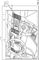
- FIG. 1 shows an example partial view of one type of environment for a driver assistance system: an interior of a cabin 100 of a vehicle 102, in which a driver and/or one or more passengers may be seated.
- Vehicle 102 of FIG. 1 may be a motor vehicle including drive wheels (not shown) and an internal combustion engine 104.
- Vehicle 102 may be a leading vehicle or a trailing vehicle.
- Internal combustion engine 104 may include one or more combustion chambers which may receive intake air via an intake passage and exhaust combustion gases via an exhaust passage.
- Vehicle 102 may be a road automobile, among other types of vehicles.
- vehicle 102 may include a hybrid propulsion system including an energy conversion device operable to absorb energy from vehicle motion and/or the engine and convert the absorbed energy to an energy form suitable for storage by an energy storage device.
- Vehicle 102 may include a fully electric vehicle, incorporating fuel cells, solar energy capturing elements, and/or other energy storage systems for powering the vehicle.
- an instrument panel 106 may include various displays and controls accessible to a driver (also referred to as the user) of vehicle 102.
- instrument panel 106 may include a touch screen 108 of an in-vehicle computing system 109 (e.g., an infotainment system), an audio system control panel, and an instrument cluster 110.
- an in-vehicle computing system 109 e.g., an infotainment system
- an audio system control panel e.g., an infotainment system
- the vehicle may include an audio system control panel, which may include controls for a conventional vehicle audio system such as a radio, compact disc player, MP3 player, etc.
- the audio system controls may include features for controlling one or more aspects of audio output via speakers 112 of a vehicle speaker system.
- the in-vehicle computing system or the audio system controls may control a volume of audio output, a distribution of sound among the individual speakers of the vehicle speaker system, an equalization of audio signals, and/or any other aspect of the audio output.
- in-vehicle computing system 109 may adjust a radio station selection, a playlist selection, a source of audio input (e.g., from radio or CD or MP3), etc., based on user input received directly via touch screen 108, or based on data regarding the user (such as a physical state and/or environment of the user) received via external devices 150 and/or mobile device 128.
- one or more hardware elements of in-vehicle computing system 109 may form an integrated head unit that is installed in instrument panel 106 of the vehicle.
- the head unit may be fixedly or removably attached in instrument panel 106.
- one or more hardware elements of the in-vehicle computing system may be modular and may be installed in multiple locations of the vehicle.
- the cabin 100 may include one or more sensors for monitoring the vehicle, the user, and/or the environment.
- the cabin 100 may include one or more seat-mounted pressure sensors configured to measure the pressure applied to the seat to determine the presence of a user, door sensors configured to monitor door activity, humidity sensors to measure the humidity content of the cabin, microphones to receive user input in the form of voice commands, to enable a user to conduct telephone calls, and/or to measure ambient noise in the cabin 100, etc.
- the above-described sensors and/or one or more additional or alternative sensors may be positioned in any suitable location of the vehicle.
- sensors may be positioned in an engine compartment, on an external surface of the vehicle, and/or in other suitable locations for providing information regarding the operation of the vehicle, ambient conditions of the vehicle, a user of the vehicle, etc.
- Information regarding ambient conditions of the vehicle, vehicle status, or vehicle driver may also be received from sensors external to/separate from the vehicle (that is, not part of the vehicle system), such as sensors coupled to external devices 150 and/or mobile device 128.
- Cabin 100 may also include one or more user objects, such as mobile device 128, that are stored in the vehicle before, during, and/or after travelling.
- the mobile device 128 may include a smart phone, a tablet, a laptop computer, a portable media player, and/or any suitable mobile computing device.
- the mobile device 128 may be connected to the in-vehicle computing system via communication link 130.
- the communication link 130 may be wired (e.g., via Universal Serial Bus [USB], Mobile High-Definition Link [MHL], High-Definition Multimedia Interface [HDMI], Ethernet, etc.) or wireless (e.g., via BLUETOOTH, WIFI, WIFI direct Near-Field Communication [NFC], cellular connectivity, etc.) and configured to provide two-way communication between the mobile device and the in-vehicle computing system.
- the mobile device 128 may include one or more wireless communication interfaces for connecting to one or more communication links (e.g., one or more of the example communication links described above).
- the wireless communication interface may include one or more physical devices, such as antenna(s) or port(s) coupled to data lines for carrying transmitted or received data, as well as one or more modules/drivers for operating the physical devices in accordance with other devices in the mobile device.
- the communication link 130 may provide sensor and/or control signals from various vehicle systems (such as vehicle audio system, climate control system, etc.) and the touch screen 108 to the mobile device 128 and may provide control and/or display signals from the mobile device 128 to the in-vehicle systems and the touch screen 108.
- the communication link 130 may also provide power to the mobile device 128 from an in-vehicle power source in order to charge an internal battery of the mobile device.
- In-vehicle computing system 109 may also be communicatively coupled to additional devices operated and/or accessed by the user but located external to vehicle 102, such as one or more external devices 150.
- external devices are located outside of vehicle 102 though it will be appreciated that in alternate embodiments, external devices may be located inside cabin 100.
- the external devices may include a server computing system, personal computing system, portable electronic device, electronic wrist band, electronic head band, portable music player, electronic activity tracking device, pedometer, smart-watch, GPS system, etc.
- External devices 150 may be connected to the in-vehicle computing system via communication link 136 which may be wired or wireless, as discussed with reference to communication link 130, and configured to provide two-way communication between the external devices and the in-vehicle computing system.
- external devices 150 may include one or more sensors and communication link 136 may transmit sensor output from external devices 150 to in-vehicle computing system 109 and touch screen 108.
- External devices 150 may also store and/or receive information regarding contextual data, user behavior/preferences, operating rules, etc. and may transmit such information from the external devices 150 to in-vehicle computing system 109 and touch screen 108.
- In-vehicle computing system 109 may analyze the input received from external devices 150, mobile device 128, and/or other input sources and select settings for various in-vehicle systems (such as climate control system or audio system), provide output via touch screen 108 and/or speakers 112, communicate with mobile device 128 and/or external devices 150, and/or perform other actions based on the assessment. In some embodiments, all or a portion of the assessment may be performed by the mobile device 128 and/or the external devices 150. In some embodiments, the external devices 150 may include in-vehicle computing devices of another vehicle, as such the vehicle may be a vehicle leading the vehicle 102, or may be a vehicle trailing behind vehicle 102.
- one or more of the external devices 150 may be communicatively coupled to in-vehicle computing system 109 indirectly, via mobile device 128 and/or another of the external devices 150.
- communication link 136 may communicatively couple external devices 150 to mobile device 128 such that output from external devices 150 is relayed to mobile device 128.
- Data received from external devices 150 may then be aggregated at mobile device 128 with data collected by mobile device 128, the aggregated data then transmitted to in-vehicle computing system 109 and touch screen 108 via communication link 130. Similar data aggregation may occur at a server system and then transmitted to in-vehicle computing system 109 and touch screen 108 via communication link 136/130.
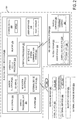
- FIG. 2 shows a block diagram of an in-vehicle computing system 200 configured and/or integrated inside vehicle 201.
- In-vehicle computing system 200 may be an example of in-vehicle computing system 109 of FIG. 1 and/or may perform one or more of the methods described herein in some embodiments.
- the in-vehicle computing system may be a vehicle infotainment system configured to provide information-based media content (audio and/or visual media content, including entertainment content, navigational services, etc.) to a vehicle user to enhance the operator's in-vehicle experience.
- information-based media content audio and/or visual media content, including entertainment content, navigational services, etc.
- the vehicle infotainment system may include, or be coupled to, various vehicle systems, sub-systems, hardware components, as well as software applications and systems that are integrated in, or integratable into, vehicle 201 in order to enhance an in-vehicle experience for a driver and/or a passenger.
- In-vehicle computing system 200 may include one or more processors including an operating system processor 214 and an interface processor 220.
- Operating system processor 214 may execute an operating system on the in-vehicle computing system, and control input/output, display, playback, and other operations of the in-vehicle computing system.
- Interface processor 220 may interface with a vehicle control system 230 via an intra-vehicle system communication module 222.
- Intra-vehicle system communication module 222 may output data to other vehicle systems 231 and vehicle control elements 261, while also receiving data input from other vehicle components and systems 231, 261, e.g. by way of vehicle control system 230. When outputting data, intra-vehicle system communication module 222 may provide a signal via a bus corresponding to any status of the vehicle, the vehicle surroundings, or the output of any other information source connected to the vehicle.
- Vehicle data outputs may include, for example, analog signals (such as current velocity), digital signals provided by individual information sources (such as clocks, thermometers, location sensors such as Global Positioning System [GPS] sensors, etc.), digital signals propagated through vehicle data networks (such as an engine controller area network [CAN] bus through which engine related information may be communicated, a climate control CAN bus through which climate control related information may be communicated, and a multimedia data network through which multimedia data is communicated between multimedia components in the vehicle).
- vehicle data networks such as an engine controller area network [CAN] bus through which engine related information may be communicated, a climate control CAN bus through which climate control related information may be communicated, and a multimedia data network through which multimedia data is communicated between multimedia components in the vehicle.
- the in-vehicle computing system may retrieve from the engine CAN bus the current speed of the vehicle estimated by the wheel sensors, a power state of the vehicle via a battery and/or power distribution system of the vehicle, an ignition state of the vehicle, etc.
- other interfacing means such as Ethernet
- a non-volatile storage device 208 may be included in in-vehicle computing system 200 to store data such as instructions executable by processors 214 and 220 in non-volatile form.
- the storage device 208 may store application data to enable the in-vehicle computing system 200 to run an application for connecting to a cloud-based server and/or collecting information for transmission to the cloud-based server.
- the application may retrieve information gathered by vehicle systems/sensors, input devices (e.g., user interface 218), devices in communication with the in-vehicle computing system (e.g., a mobile device connected via a Bluetooth link), etc.
- In-vehicle computing system 200 may further include a volatile memory 216. Volatile memory 216 may be random access memory (RAM).
- Non-transitory storage devices such as non-volatile storage device 208 and/or volatile memory 216, may store instructions and/or code that, when executed by a processor (e.g., operating system processor 214 and/or interface processor 220), controls the in-vehicle computing system 200 to perform one or more of the actions described in the invention.
- a processor e.g., operating system processor 214 and/or interface processor 220
- a microphone 202 may be included in the in-vehicle computing system 200 to receive voice commands from a user, to measure ambient noise in the vehicle, to determine whether audio from speakers of the vehicle is tuned in accordance with an acoustic environment of the vehicle, etc.
- a speech processing unit 204 may process voice commands, such as the voice commands received from the microphone 202.
- in-vehicle computing system 200 may also be able to receive voice commands and sample ambient vehicle noise using a microphone included in an audio system 232 of the vehicle.
- One or more additional sensors may be included in a sensor subsystem 210 of the in-vehicle computing system 200.
- the sensor subsystem 210 may include a camera, such as a rear view camera for assisting a user in parking the vehicle and/or a cabin camera for identifying a user (e.g., using facial recognition and/or user gestures).
- Sensor subsystem 210 of in-vehicle computing system 200 may communicate with and receive inputs from various vehicle sensors and may further receive user inputs.
- the inputs received by sensor subsystem 210 may include transmission gear position, transmission clutch position, gas pedal input, brake input, transmission selector position, vehicle speed, engine speed, mass airflow through the engine, ambient temperature, intake air temperature, etc., as well as inputs from climate control system sensors (such as heat transfer fluid temperature, antifreeze temperature, fan speed, passenger compartment temperature, desired passenger compartment temperature, ambient humidity, etc.), an audio sensor detecting voice commands issued by a user, a fob sensor receiving commands from and optionally tracking the geographic location/proximity of a fob of the vehicle, etc. While certain vehicle system sensors may communicate with sensor subsystem 210 alone, other sensors may communicate with both sensor subsystem 210 and vehicle control system 230, or may communicate with sensor subsystem 210 indirectly via vehicle control system 230.
- climate control system sensors such as heat transfer fluid temperature, antifreeze temperature, fan speed, passenger compartment temperature, desired passenger compartment temperature, ambient humidity, etc.
- an audio sensor detecting voice commands issued by a user
- a fob sensor receiving commands from and optionally tracking the geographic
- a navigation subsystem 211 of in-vehicle computing system 200 may generate and/or receive navigation information such as location information (e.g., via a GPS sensor and/or other sensors from sensor subsystem 210), route guidance, traffic information, point-of-interest (POI) identification, and/or provide other navigational services for the driver.
- location information e.g., via a GPS sensor and/or other sensors from sensor subsystem 210
- POI point-of-interest
- External device interface 212 of in-vehicle computing system 200 may be coupleable to and/or communicate with one or more external devices 240 located external to vehicle 201. While the external devices are illustrated as being located external to vehicle 201, it is to be understood that they may be temporarily housed in vehicle 201, such as when the user is operating the external devices while operating vehicle 201. In other words, the external devices 240 are not integral to vehicle 201.
- the external devices 240 may include a mobile device 242 (e.g., connected via a Bluetooth, NFC, WIFI direct, or other wireless connection) or an alternate Bluetooth-enabled device 252.
- Mobile device 242 may be a mobile phone, smart phone, wearable devices/sensors that may communicate with the in-vehicle computing system via wired and/or wireless communication, or other portable electronic device(s).
- Other external devices include external services 246.
- the external devices may include extra-vehicular devices that are separate from and located externally to the vehicle.
- Still other external devices include external storage devices 254, such as solid-state drives, pen drives, USB drives, etc.
- External devices 240 may communicate with in-vehicle computing system 200 either wirelessly or via connectors.
- external devices 240 may communicate with in-vehicle computing system 200 through the external device interface 212 over network 260, a universal serial bus (USB) connection, a direct wired connection, a direct wireless connection, and/or other communication link.
- USB universal serial bus
- the external device interface 212 may provide a communication interface to enable the in-vehicle computing system to communicate with mobile devices associated with contacts of the driver.
- the external device interface 212 may enable phone calls to be established and/or text messages (e.g., SMS, MMS, etc.) to be sent (e.g., via a cellular communications network) to a mobile device associated with a contact of the driver.
- the external device interface 212 may additionally or alternatively provide a wireless communication interface to enable the in-vehicle computing system to synchronize data with one or more devices in the vehicle (e.g., the driver's mobile device) via WIFI direct, as described in more detail below.
- One or more applications 244 may be operable on mobile device 242.
- mobile device application 244 may be operated to aggregate user data regarding interactions of the user with the mobile device.
- mobile device application 244 may aggregate data regarding music playlists listened to by the user on the mobile device, telephone call logs (including a frequency and duration of telephone calls accepted by the user), positional information including locations frequented by the user and an amount of time spent at each location, etc.
- the collected data may be transferred by application 244 to external device interface 212 over network 260.
- specific user data requests may be received at mobile device 242 from in-vehicle computing system 200 via the external device interface 212.
- the specific data requests may include requests for determining where the user is geographically located, an ambient noise level and/or music genre at the user's location, an ambient weather condition (temperature, humidity, etc.) at the user's location, etc.
- Mobile device application 244 may send control instructions to components (e.g., microphone, etc.) or other applications (e.g., navigational applications) of mobile device 242 to enable the requested data to be collected on the mobile device. Mobile device application 244 may then relay the collected information back to in-vehicle computing system 200.
- one or more applications 248 may be operable on external services 246.
- external services applications 248 may be operated to aggregate and/or analyze data from multiple data sources.
- external services applications 248 may aggregate data from one or more social media accounts of the user, data from the in-vehicle computing system (e.g., sensor data, log files, user input, etc.), data from an internet query (e.g., weather data, POI data), etc.
- the collected data may be transmitted to another device and/or analyzed by the application to determine a context of the driver, vehicle, and environment and perform an action based on the context (e.g., requesting/sending data to other devices).
- Vehicle control system 230 may include controls for controlling aspects of various vehicle systems 231 involved in different in-vehicle functions. These may include, for example, controlling aspects of vehicle audio system 232 for providing audio entertainment to the vehicle occupants, aspects of climate control system 234 for meeting the cabin cooling or heating needs of the vehicle occupants, as well as aspects of telecommunication system 236 for enabling vehicle occupants to establish telecommunication linkage with others.
- Audio system 232 may include one or more acoustic reproduction devices including electromagnetic transducers such as speakers. Vehicle audio system 232 may be passive or active such as by including a power amplifier. In some examples, in-vehicle computing system 200 may be the only audio source for the acoustic reproduction device or there may be other audio sources that are connected to the audio reproduction system (e.g., external devices such as a mobile phone). The connection of any such external devices to the audio reproduction device may be analog, digital, or any combination of analog and digital technologies.
- climate control system 234 may be configured to provide a comfortable environment within the cabin or passenger compartment of vehicle 201.
- climate control system 234 includes components enabling controlled ventilation such as air vents, a heater, an air conditioner, an integrated heater and air-conditioner system, etc.
- Other components linked to the heating and air-conditioning setup may include a windshield defrosting and defogging system capable of clearing the windshield and a ventilation-air filter for cleaning outside air that enters the passenger compartment through a fresh-air inlet.
- Vehicle control system 230 may also include controls for adjusting the settings of various vehicle controls 261 (or vehicle system control elements) related to the engine and/or auxiliary elements within a cabin of the vehicle, such as steering wheel controls 262 (e.g., steering wheel-mounted audio system controls, cruise controls, windshield wiper controls, headlight controls, turn signal controls, etc.), instrument panel controls, microphone(s), accelerator/brake/clutch pedals, a gear shift, door/window controls positioned in a driver or passenger door, seat controls, cabin light controls, audio system controls, cabin temperature controls, etc.
- steering wheel controls 262 e.g., steering wheel-mounted audio system controls, cruise controls, windshield wiper controls, headlight controls, turn signal controls, etc.
- instrument panel controls e.g., instrument panel controls, microphone(s), accelerator/brake/clutch pedals, a gear shift, door/window controls positioned in a driver or passenger door, seat controls, cabin light controls, audio system controls, cabin temperature controls, etc.
- Vehicle controls 261 may also include internal engine and vehicle operation controls (e.g., engine controller module, actuators, valves, etc.) that are configured to receive instructions via the CAN bus of the vehicle to change operation of one or more of the engine, exhaust system, transmission, and/or other vehicle system.
- the control signals may also control audio output at one or more speakers of the vehicle's audio system 232.
- the control signals may adjust audio output characteristics such as volume, equalization, audio image (e.g., the configuration of the audio signals to produce audio output that appears to a user to originate from one or more defined locations), audio distribution among a plurality of speakers, etc.
- the control signals may control vents, air conditioner, and/or heater of climate control system 234.
- the control signals may increase delivery of cooled air to a specific section of the cabin.
- Control elements positioned on an outside of a vehicle may also be connected to computing system 200, such as via communication module 222.
- the control elements of the vehicle control system may be physically and permanently positioned on and/or in the vehicle for receiving user input.
- vehicle control system 230 may also receive input from one or more external devices 240 operated by the user, such as from mobile device 242. This allows aspects of vehicle systems 231 and vehicle controls 261 to be controlled based on user input received from the external devices 240.
- In-vehicle computing system 200 may further include an antenna 206.
- Antenna 206 is shown as a single antenna, but may comprise one or more antennas in some embodiments.
- the in-vehicle computing system may obtain broadband wireless internet access via antenna 206, and may further receive broadcast signals such as radio, television, weather, traffic, and the like.
- the in-vehicle computing system may receive positioning signals such as GPS signals via one or more antennas 206.
- the in-vehicle computing system may also receive wireless commands via RF such as via antenna(s) 206 or via infrared or other means through appropriate receiving devices.
- antenna 206 may be included as part of audio system 232 or telecommunication system 236. Additionally, antenna 206 may provide AM/FM radio signals to external devices 240 (such as to mobile device 242) via external device interface 212.
- One or more elements of the in-vehicle computing system 200 may be controlled by a user via user interface 218.
- User interface 218 may include a graphical user interface presented on a touch screen, such as touch screen 108 of FIG. 1 , and/or user-actuated buttons, switches, knobs, dials, sliders, etc.
- user-actuated elements may include steering wheel controls, door and/or window controls, instrument panel controls, audio system settings, climate control system settings, and the like.
- a user may also interact with one or more applications of the in-vehicle computing system 200 and mobile device 242 via user interface 218.
- vehicle settings selected by in-vehicle control system may be displayed to a user on user interface 218.
- Notifications and other messages e.g., received messages
- navigational assistance may be displayed to the user on a display of the user interface.
- User preferences/information and/or responses to presented messages may be performed via user input to the user interface.
- FIG. 3 shows a block diagram of an example navigation system in a trailing vehicle in accordance with one or more embodiments of the present invention.
- the navigation system 300 of the trailing vehicle may communicate with a navigation system of a leading vehicle 318 as described below.
- the navigation system 300 includes a processor 302, a memory/storage device 310, a display 316, a sensor input 304, a user input interface 306, a navigation input interface 308, an inter-vehicle communication system 312, and intra-vehicle communication system 314.
- the navigation system may be configured as a component of a motor vehicle navigation system (e.g., in-vehicle computing system, 109 of FIG. 1 /in-vehicle computing system 200 of FIG. 2 ), as a handheld device, as a component of a smart phone, and/or as any other suitable computing device(s).
- the processor may be an example of the operating system, processor 214 of FIG. 2 , and may further include the interface processor 220 of FIG.
- the processor 302 may receive a user input via the user input interface 306, which may be a module or port for receiving user input from a user input device connected to the navigation system and/or from a user interface of the navigation system (e.g., a graphical user interface [GUI]).
- GUI graphical user interface
- the user (or driver) of a vehicle may input on the display 316 (e.g., a touch-sensitive display), a desire to follow a leading vehicle, for example.
- the processor 302 may communicate or transmit this information to the navigation system of the leading vehicle 318 via the inter-vehicle communication system 312.
- the inter-vehicle communication system 312 may receive additional information and/or signal(s) from the navigation system of the leading vehicle 318 and transmit it to the processor 302 for additional processing.
- the processor receives additional inputs from plurality of sensors both mounted on the vehicle, and located external to the vehicle. In some examples, the sensors are cameras. As such, pictures or videos of a region surrounding the vehicle taken by cameras mounted on the vehicle may be received by the processor 302. This input may further be analyzed to decipher information from the received images and/or videos.
- the processor 302 may additionally retrieve input stored in the memory/storage device 310. For example, the driver may store a preference to automatically follow a leading vehicle when in a no-pass zone.
- the driver may additionally or alternatively save details on a desired separation (or space cushion) to follow the leading vehicle in the memory/storage device 310 as historical data which may be subsequently retrieved by the processor 302.
- the processor 302 may be capable of adaptively learning to anticipate a driver's desire to follow a leading vehicle based on the historical data stored in the memory/storage device.
- no-passing zone ahead signal may be detected by a camera mounted on the vehicle.
- the camera mounted on the vehicle may capture images of two solid yellow line markings on the road, and, based on the images processed by the processor 302, the processor may identify that the vehicle is in a no-pass zone for example.
- the no-pass zone may also be identified based on road signs (such as "NO PASSING ZONE" or "NO-PASS ZONE” signs or signs having graphical representations of a no passing zone, such as a depiction of two cars in parallel with one another and an "x" through one of the cars) posted along the roads, or additionally and/or alternatively identified based on navigational input 308.
- the no-passing zone ahead signal may be deduced based on navigation input from a GPS. For example, based on a current location of the vehicle, the processor may receive locations of no-pass zones along a route that the current vehicle is travelling. The processor 302 may identify upcoming no-pass zones based on such navigational input. Once a no-passing zone or no-passing zone ahead signal is detected, the user or driver of the current vehicle may indicate a desire (e.g., a request) to follow a leading vehicle. As such, the request to automatically follow the leading vehicle may be stored as a user preference in memory/storage device 310, and further retrieved by the processor 302.
- a desire e.g., a request
- Automatic following may include one or more combinations of engaging auto-pilot and/or engaging an automatic vehicle control routine by increasing an amount of control of the vehicle automatically provided by one or more vehicle control systems (such as vehicle control system, 230 of FIG. 2 ), and decreasing manual control of the vehicle by the driver.
- the control of the vehicle control systems may be communicated via the intra-vehicle communication system 314 (e.g., intra-vehicle communication module, 222 of FIG. 2 ).
- the processor 302 may wait to perform the action of engaging automatic vehicle control routine until a leading vehicle is detected.
- the leading vehicle may be detected based on sensor input 304 (e.g., based on a camera mounted in the front of the vehicle capturing an image of a vehicle immediately in front of the vehicle, at a threshold distance, for example).
- sensor input 304 e.g., based on a camera mounted in the front of the vehicle capturing an image of a vehicle immediately in front of the vehicle, at a threshold distance, for example.
- the request of the driver of the current (trailing) vehicle may be communicated to a navigation system, of the leading vehicle 318, transmitted via one or more or wireless networks and Bluetooth.
- the intra-vehicle processor may transmit signals to the vehicle controls and further engage an automatic vehicle control routine and/or auto-pilot of the vehicle.
- the automatic vehicle control routine of the vehicle may include automatically adjusting vehicle control systems with minimal/decreased driver intervention/control.
- the automatic vehicle control routine of the trailing vehicle may further include details of adjusting the vehicle control systems to maintain a threshold speed of the trailing vehicle for a threshold distance at a threshold separation from the leading vehicle as described in FIG. 4 .
- one or more vehicle control commands such as steering, acceleration/speed/braking, gear shifting, and/or other commands may be provided automatically by one or more vehicle systems (e.g., based on instructions from the leading vehicle and/or from a processor of the vehicle).
- vehicle systems e.g., based on instructions from the leading vehicle and/or from a processor of the vehicle.
- driver-initiated vehicle control commands e.g., for the steering, acceleration/speed/braking, gear shifting, etc.
- the vehicle may not respond to some or all driver-initiated commands (e.g., from a driver of the vehicle to one or more driver control devices, such as a steering wheel, gas/accelerator pedal, brake pedal, parking brake, gear shifter, and/or other device for accepting driver input to control driving operation of the vehicle) during the automatic vehicle control routine.
- driver may provide an automatic vehicle control override input that enables the system to quickly return at least some controls to the driver.
- the return of the controls may be provided responsive to receiving a threshold number, type, or degree of driver-initiated control inputs during operation under the automatic vehicle control routine (e.g., a request for braking that exceeds a threshold braking request [e.g., a position of the brake pedal being moved to within a threshold distance of the fully-depressed position]).
- a threshold number, type, or degree of driver-initiated control inputs during operation under the automatic vehicle control routine
- some vehicle controls may remain responsive to driver commands even while operating the automatic vehicle control routine. For example, the driver may be able to depress a brake pedal to brake the vehicle even while operating under the automatic vehicle control routine.
- driver input to other vehicle systems may be ignored by the vehicle and/or otherwise may not be provided as control commands to an associated vehicle system (e.g., an engine, transmission, fuel injector, throttle, etc.).
- an associated vehicle system e.g., an engine, transmission, fuel injector, throttle, etc.
- all or a majority of the above-described vehicle commands may be provided by the driver and none or a minority of the above-described vehicle commands may be provided automatically by the vehicle, signals from a leading vehicle, and/or a processor of the vehicle.
- the navigation system 300 may further include a passing assistance calculator (not shown).
- the driver of the trailing vehicle may indicate a request to pass or a request not to pass, and following distance and/or other parameters may be controlled differently depending on the type of request received.
- the passing assistance calculator may calculate a distance to overtake based on engine power limits, speed of leading vehicle, distance to leading vehicle, and where in road ahead the passing is no longer allowed (e.g., when the road switches from passing allowed to passing not allowed), and further based on whether there is more than one leading vehicle.
- the parameters may further be adjusted based on acceleration and/or deceleration of forward vehicle, and based on expected grade of road that the vehicle will traverse during the passing operation.
- the navigation system 300 may then inform the driver of a recommended overtake velocity that may result in a safe, successful, and timely pass. If the request is to not pass, the following distance and/or other parameters may be maintained at a previously-determined/set level.
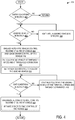
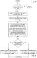
- FIG. 4 shows an example method 400 for driver assistance with respect to following a leading vehicle in accordance with one or more embodiments of the present invention. Specifically, the method includes automatic control of the vehicle when one or more entry conditions are met, and subsequently discontinuing automatic control when one or more exit conditions are met. In some examples, method 400 may be performed by the navigation system 300 illustrated in FIG. 3 .
- Method 400 begins by checking if entry conditions of a current vehicle are detected at 402.
- Entry conditions may include, but are not limited to, identifying start of one or more of a no-passing zone, a narrow lane zone, a one-lane zone, a construction/road-work ahead zone, and a slippery zone.
- the detection may be based on inputs from sensors (such as cameras, GPS, etc.). For example, when the camera mounted on the vehicle detects a "NO-PASS ZONE" sign or detects double yellow line markings on the road or detects "OVERTAKING PROHIBITED” sign, an entry condition may be considered to be detected.
- detecting a narrow-lane sign and/or a one-lane sign may indicate that an entry condition is detected.
- slippery roads may be detected based on one or more of sensor data, navigation data, and vehicle condition/traction data.
- the detection may be based on a driver preference. As such, the driver/user may enter a preference to automatically follow a leading vehicle.
- entry conditions may be considered to be met and automatic control of the vehicle may be initiated as described below.
- entry conditions are not detected at 402, then the method returns (e.g., without initiating an automatic vehicle control routine). However, if entry conditions are detected at 402, then method proceeds to 404 to determine whether a leading vehicle is detected.
- the leading vehicle may be defined as the vehicle immediately in front of the current vehicle, with no vehicle there between. In other examples, a vehicle may be considered a leading vehicle if that vehicle is at a threshold distance ahead of the current/trailing vehicle.
- the leading vehicle may be detected by the camera on the current vehicle, for example. However, if leading vehicle is not detected or the vehicle in front of the current vehicle is at a distance greater than the threshold distance, then method proceeds to 406 to wait until a leading vehicle is detected (e.g., to continue polling for the leading vehicle at 404).
- method proceeds to 408 to send control instructions to the vehicle control systems to engage autopilot and/or an automatic control routine of the current vehicle.
- Engaging autopilot and/or automatic control routine of the current vehicle at 408 may include disengaging driver control of the vehicle at 410.
- Disengaging driver control may include one or more of decreasing an amount of control of the vehicle provided by the driver of the vehicle (also referred to as manual control of the vehicle), and increasing an amount of control of the vehicle automatically provided by one or more vehicle systems at 410 (e.g., without driver intervention).
- Engaging autopilot and/or automatic vehicle control may additionally or alternatively include automatically following the leading vehicle at a threshold speed and at a threshold separation (also referred to as space cushion) at 412.
- the threshold speed may be determined based on a speed limit in the stretch of road and further adjusted based on the driving and vehicle conditions and/or user preferences (e.g., as set by the driver of the leading and/or trailing vehicle). As an example, if the speed limit on the stretch of road is 35mph, then the threshold speed for automatic control of the vehicle may be set to 35mph. However, the threshold speed may be reduced to a lower number (e.g., 25 mph) if the weather conditions include rain, snow, sleet, etc. In some other examples, the driver (one or more of the driver of the leading vehicle and the driver of the leading vehicle) may input the threshold speed. The threshold speed may further be adjusted based on the type of entry condition detected.
- the threshold speed may be adjusted to 5-10 mph lower than the speed limit posted in the zone.
- threshold separation or space cushion may be determined.
- the space cushion is described in detail in FIGS. 7-9 . Briefly, the space cushion is the separation between a leading vehicle and a trailing vehicle. The space cushion may be further adjusted based on user driving habit, user driving skill, and/or user distraction level of one or more of a driver of the leading vehicle and a driver of the trailing vehicle. In some examples, the space cushion may be a function of the road signs.
- a threshold distance to follow the leading vehicle may be determined.
- the threshold distance to follow may be based on one or more of navigation data, vehicle data, user preference, etc.
- the threshold distance may be adjusted based on the type of entry condition detected.
- the threshold distance may be determined based on the driver preference.
- the driver preference may include one or more preferences from the driver of the trailing vehicle and/or the driver of the leading vehicle.
- the threshold distance to follow a leading vehicle may correspond to the distance from a location of the vehicle when the entry condition is detected to a location of the vehicle when an exit condition is detected. For example, the trailing vehicle may automatically follow the leading vehicle until the end of the no-pass zone for example.
- Exit conditions may include identifying an end of one or more of the no-passing zone, the narrow lane zone, the one-lane zone, the construction/road work ahead zone, and the slippery road.
- the driver of one or more of the trailing and the leading vehicle may be able to override the automatic control of the trailing vehicle at any time. For example, if the driver provides a request not to automatically follow the leading vehicle, the exit conditions may be considered to be met.
- method 400 proceeds to 418, where the current vehicle may be continued to be driven via autopilot, wherein the vehicle may be automatically controlled via an automatic vehicle control routine in which manual control of the vehicle is reduced relative to a standard or manual vehicle control routine, for example. As indicated at 418, the speed and/or trailing distance of the trailing vehicle may be maintained. However, if exit conditions are detected at 416, then method 400 proceeds to 420, where the autopilot may be disengaged (e.g., automatic vehicle control is exited and a manual vehicle control routine is initiated, returning at least some control of the vehicle to the driver) and additionally, the driver may be intimated to take manual control of the vehicle at 422, following which the method returns.
- autopilot may be disengaged (e.g., automatic vehicle control is exited and a manual vehicle control routine is initiated, returning at least some control of the vehicle to the driver) and additionally, the driver may be intimated to take manual control of the vehicle at 422, following which the method returns.
- Disengaging of autopilot at 420 and intimation of driver at 422 may be performed concurrently or sequentially. In this way, the driver may be relieved from having to negotiate through mundane stretches. By not actively participating in the negotiation, and by not participating in the vehicle control, the driver may be able to get some rest and reduce mental stress. The reduced mental stress may further stave off driver fatigue. Therefore, when the driver returns to actively driving, the driver may be more alert compared to a driver who has had to negotiate through the mundane stretches.
- the method 400 is described as executed by the trailing vehicle, wherein the trailing vehicle follows the leading vehicle automatically at the threshold separation during automatic vehicle control.
- the method 400 may be additionally or alternatively executed in the leading vehicle whereby the leading vehicle may determine the space cushion at which it would like to be followed during automatic vehicle control.
- the leading vehicle may communicate the preferences to the trailing vehicle and/or the commands to control the vehicle systems of the trailing vehicle to operate the trailing vehicle according to the preferences. It is to be understood that any control signals received from outside the trailing vehicle may be accepted by the driver of the trailing vehicle before being executed.
- methods for selectively entering an automatic vehicle control routine and/or calculating a trailing distance may be executed by one or more of the leading/trailing vehicles to communicate with one or more of immediately leading/trailing vehicles respectively.
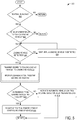
- FIG. 5 shows an example method for providing driver assistance to a trailing vehicle in a no-pass zone in accordance with one or more embodiments of the present invention. Specifically, the method includes activating autopilot or automatic control of the vehicle based on detecting the no-pass zone.
- method 500 may be performed by the navigation system 300 illustrated in FIG. 3 .
- the method includes determining if a no-pass zone is detected.
- the no-pass zone may be detected based on the cameras detecting a no-pass signal on the street, for example.
- a no-pass zone may be detected based on double yellow markings on the road as detected by cameras mounted on the front of the vehicle.
- the no-pass may additionally or alternatively be detected based on navigation input received from the GPS. If a no-pass zone is not detected, then method returns (e.g., to maintain a current level of manual vehicle control and/or without engaging an autopilot and/or automatic vehicle control routine). However, if a no-pass zone is detected, then method proceeds to 504, where a driver preference may be checked.
- the processor may determine whether the driver preference is to follow a leading vehicle. As such, when the no-pass zone is detected, the driver may be asked if he/she would like to follow the leading vehicle. If "NO", then method returns. In additional or alternative examples, the driver preference may be learned based on driving record/historical data retrieved from memory. If the driver preference is to follow the leading vehicle, then method 500 proceeds to 506, to determine whether a leading vehicle is detected.
- the leading vehicle may include the vehicle immediately ahead of the current vehicle, with no vehicle there between.
- the leading vehicle may further include vehicle at a threshold distance from the current vehicle.
- the leading vehicle may be detected by cameras mounted on the front of the current vehicle, for example.
- method proceeds to 508, where the method includes instructions to wait until a leading vehicle is detected. Once the leading vehicle is detected, then method proceeds to 510, where the desire/request to follow the leading vehicle by the current vehicle (also referred to as the trailing vehicle), is transmitted to the leading vehicle. Next, at 512, the trailing vehicle receives communication from the leading vehicle. If the communication received (or feedback from the leading vehicle) is "NO-FOLLOW" and/or otherwise indicates that the trailing vehicle is not permitted to follow the leading vehicle, then the method proceeds to 516, wherein the autopilot or automatic vehicle control routine is not activated.
- the method proceeds to 518 where autopilot or automatic vehicle control routine of the trailing vehicle is activated as described in FIG. 6 .
- the trailing vehicle may operate as though a permission to follow was received, and automatically follow the leading vehicle as described at 518 until "NO-FOLLOW" is received or another exit condition is met.
- FIG. 6 an example method 600 for determining a threshold separation, a threshold speed, and a threshold distance (e.g., total travelling distance) to follow the leading vehicle.
- method 600 may be performed by the navigation system 300 illustrated in FIG. 3 .
- the method includes determining a threshold separation (or space cushion) at which to follow the leading vehicle.
- the threshold separation may be defined as the distance at which the trailing vehicle follows the leading vehicle (e.g., the distance between the trailing vehicle and the leading vehicle).
- the threshold separation may include the distance at which the leading vehicle desires to be followed by a trailing vehicle (e.g., according to a user preference and/or vehicle system setting).
- the threshold separation may be based on environmental conditions determined at 604. For example, during rain or snow, the vehicle traction may be reduced, and the threshold separation may be increased to take this into account.
- the threshold separation may be further adjusted based on the type of road (construction zone, for example) condition of the road (slippery road, gravel road, for example), bends and curves on road, visibility, inclement weather, heavy traffic, night-time driving, vehicle speed etc.
- the separation may additionally or alternatively be based on vehicle conditions determined at 606 and/or driver preference (as retrieved at 608). In poor driving conditions such as heavy rain or snow, the vehicle traction may play a key role in the vehicle control. Depending on the condition of the tires, brakes, presence or absence of traction control system and electronic stability control, and/or other factors, the threshold separation may be further adjusted. For example, if the vehicle has good set of tires with newer threads, then the threshold separation may not be increased, however, if the tire threads are relatively shallow and worn out, and then the threshold separation may be increased at 606. The threshold separation may be reduced if the brakes in the vehicle have poor braking performance.
- the threshold separation may additionally or alternatively be adjusted based on driver preference.
- the navigation system of the trailing vehicle may determine the space cushion to be 100 ft, but the driver of the trailing vehicle may consider such a space cushion to be too close for his preference.
- the threshold separation may be increased to 150 ft, for example.
- a threshold speed at which to follow the leading vehicle is determined.
- the threshold speed may be further adjusted based on the speed limit information retrieved from navigation data, for example, as determined at 612.
- the navigation data may include information about the speed limit for the roads travelled.
- the threshold speed may be set to the speed limit.
- the threshold speed may then be further adjusted based on one or more road conditions determined at 614, and/or driver preference determined at 616.
- the threshold speed may be further adjusted based on the speed of the leading vehicle.
- the method proceeds to 618, where the threshold distance (e.g., total travelling distance) for following the leading vehicle is determined (e.g., based on a stored setting in memory).
- the threshold distance may be further adjusted based on one or more of data retrieved from sensors (at 620) and driver preference retrieved at 622.
- the data received from sensors may include information that the leading vehicle has taken a turn, and is no longer in the path directly in front of the trailing vehicle, for example.
- the data from the sensors may include navigational information indicating an end of a no-pass zone, construction zone, etc. For example, the distance until which to follow the leading vehicle may depend on the end of a no-pass zone.
- the driver may set a threshold distance for following the leading vehicle, which in some cases may be less than the determined distance to the end of the no-pass zone. In some examples, the driver may wish to continue the automatic trailing of the leading vehicle even when the no-pass zone has ended, in which case the threshold distance may be longer than the length of the no-pass zone.
- the threshold distance for following the leading vehicle may be expressed as a travelling distance (e.g., length of the road/travel), an amount of time, an exit condition, and/or a location at which to stop following the leading vehicle (e.g., a landmark, intersection, GPS coordinates, etc.).
- the method proceeds to 624 where autopilot and/or automatic vehicle control routine of the trailing vehicle is engaged/operated for the threshold distance at the threshold speed and with threshold separation (space cushion) maintained between the leading vehicle and the trailing vehicle.
- threshold separation space cushion
- the driver may have the option to stop following the leading vehicle at any point.
- the automatic vehicle control routine may be disengaged, and manual control of the vehicle may be initiated.
- the navigation system of the trailing vehicle may communicate with the navigation system of the leading vehicle via vehicle-to-vehicle communication routines, and be able to negotiate and determine the space cushion between the leading and the trailing vehicle.
- FIG. 7 shows a pictorial illustration 700 of the leading vehicle and the trailing vehicle separated by a distance determined as a space cushion in accordance with one or more embodiments of the present invention.
- 702 refers to the trailing vehicle
- 704 refers to leading vehicle, wherein the leading vehicle is the vehicle immediately ahead of the trailing vehicle with no other vehicle there between.
- Both the leading vehicle 704 and the trailing vehicle 702 are travelling along a road 714.
- the road 714 may include a single lane of a multi-lane roadway or highway, wherein the leading vehicle 704 and the trailing vehicle 702 occupy the same lane of the multi-lane roadway.
- the road 714 may include a single-lane road.
- the road 714 may further include one or more of a no-pass zone, a one-lane zone, a construction/road-work ahead zone, and a slippery road.
- the driver of the trailing vehicle may prefer to follow the leading vehicle in order to get some rest.
- the navigation system of the trailing vehicle may determine a 1 st separation, represented by the distance between points 706 (e.g., a trailing edge/rear bumper of the leading vehicle) and 708 of the road 714, based on one or more inputs as described earlier.
- the navigation system of the trailing vehicle may determine the 1 st separation based on one or more of environmental conditions, vehicle conditions, driver preference, etc.
- the 1 st separation may be further adjusted based on the speed of the leading and the trailing vehicles, speed limit, driver preference, etc.
- the navigation system of the trailing vehicle may communicate the 1 st separation to the navigation system of the leading vehicle (via inter-vehicle communication system 312 of FIG. 3 , for example).
- the leading vehicle may compute a second separation at which it would prefer to be followed.
- the 2 nd separation represented as the distance between points 706 and 712 (e.g., the leading edge/front bumper of the trailing vehicle) on the road 714, may further be based on similar conditions as explained with reference to the determination of the 1 st separation.
- the navigation system of the leading vehicle may communicate the 2 nd separation to the navigation system of the trailing vehicle.
- the 1 st separation and the 2 nd separation may be the same or may be different in some examples. If the 1 st separation is the same as the 2 nd separation, then the space cushion between the two vehicles may be set at the 1 st (also the 2 nd ) separation. However, if the 1st separation is different from the 2 nd separation, then the space cushion (represented as the distance between the points 706 and 710) may be determined based on one or more of an average of the 1 st and 2 nd separation, and a weighted average of the 1 st and the 2 nd separation.
- the weights may be based on driver preference, and further based on whether the vehicle is the leading or the trailing vehicle. In some examples, larger weights may be assigned to the leading vehicle. In additional or alternative examples, one of the leading vehicle and the trailing vehicle may override the opposing vehicle's separation request, or the largest separation request may be used for the space cushion.
- the space cushion may be determined in one or more of the navigation system of the trailing vehicle and the leading vehicle, and communicated to the respective leading/trailing vehicles.
- the trailing vehicle may only be allowed to follow the leading vehicle automatically once both drivers are satisfied and/or approve a selected/negotiated space cushion.
- the driver of the leading vehicle may communicate to the trailing vehicle to increase the space cushion.
- the trailing vehicle may then automatically increase the space cushion or may prompt the driver of the trailing vehicle to make a decision on whether to increase the space cushion or stop automatically following the lead vehicle.
- the communication between the vehicles may be accomplished via vehicle-to-vehicle communication systems.
- the leading vehicle may notice an emergency vehicle, road condition, or other environmental feature ahead and may transmit this information to the trailing vehicle.
- the trailing vehicle Responsive to the receipt of the forward perspective information from the leading vehicle, the trailing vehicle may adjust a space cushion, end/reduce an automatic vehicle control routine, and/or prompt the driver of the trailing vehicle to confirm the space cushion and/or ending/adjustment to the automatic control routine.
- vehicle and road safety may be enhanced by utilizing the additional perspective provided by the leading vehicle. For example, rear-end collisions may be avoided if the trailing vehicle is made aware of conditions that may cause the leading vehicle to come to an abrupt stop.
- FIG. 8 shows an example method 800 for determining the space cushion between a leading vehicle and a trailing vehicle based on various parameters and preferences.
- Method 800 may be performed in a trailing vehicle, such as a navigation system and/or an in-vehicle computing system of trailing vehicle 702 of FIG. 7 that requests to follow a leading vehicle, such as leading vehicle 704 of FIG. 7 .
- the method includes determining if the current vehicle is a trailing vehicle. If the vehicle is not a trailing vehicle, then method returns without determining a space cushion.
- method 800 relates to determining a space cushion in the trailing vehicle. An example method for determining a space cushion in the leading vehicle is described below with respect to FIG. 9 .
- a first separation is received from the current vehicle (e.g., the trailing vehicle).
- a value of the first separation e.g., a distance that the current vehicle is to maintain from the leading vehicle
- a second separation is received from the leading vehicle.
- the first separation is the separation at which the trailing vehicle requests to follow the leading vehicle, while the second separation is the distance at which the leading vehicle requests to be followed.
- a space cushion is determined (e.g., as described above with respect to FIGS. 6 and 7 ) at 808.
- the space cushion is determined to be and/or based on the average or weighted average of the first separation and the second separation as determined at 810.
- the space cushion may be further adjusted based on a user driving habit, a user driving skill, and a user distraction level as determined at 812.
- the space cushion may still further adjusted based on one or more of a vehicle condition, road condition, weather condition, and navigation data as indicated at 814.
- method proceeds to 816, where the space cushion is compared to the first and/or second separation to determine if the space cushion greater than or equal to one or more of the first separation and the second separation.
- the space cushion is compared to the separations to determine whether the space cushion exceeds or equals both the 1 st and the 2 nd separations in order to err on the side of following at a safer distance (e.g., where a larger space cushion is safer than a smaller space cushion).
- the space cushion is compared to the separations to determine whether the minimum requested separation condition is met (e.g., whether the space cushion is greater than or equal to either the first or the second separation).
- each separation may be assumed to represent a safe following distance, and a space cushion that satisfies at least one of the requested separation distances may be acceptable for use.
- the method proceeds to 818 where autopilot and/or automatic vehicle control routine of the trailing vehicle is engaged to follow the leading vehicle while maintaining a separation matching (e.g., substantially equal to) the space cushion (e.g., as determined at 808) between the leading vehicle and the trailing vehicle.
- a separation matching e.g., substantially equal to
- the space cushion as determined at 808 is less than one or more of the first separation and the second separation
- the method proceeds to 820, where the autopilot and/or automatic vehicle control of the trailing vehicle is not engaged (e.g., a manual vehicle control is engaged and/or the vehicle operates under a greater amount of manual control than at 818).
- the space cushion may be renegotiated between the trailing vehicle and the leading vehicle to determine a new space cushion if the space cushion is less than each of the first and the second separations.
- the trailing and/or leading vehicle may request a different separation and method 800 may be repeated with the new separation(s) to determine if a newly calculated space cushion is acceptable to both the leading vehicle and the trailing vehicle (e.g., if the newly calculated space cushion is greater than or equal to the updated requested separation from each vehicle).
- FIG. 9 shows an example method 900 for allowing or denying a request to follow a leading vehicle from a trailing vehicle, in accordance with one or more embodiments of the present invention.
- Method 900 may be executed in a leading vehicle, such as a navigation system and/or in-vehicle computing system of leading vehicle 704 in FIG. 7 , based on a request received from a trailing vehicle, such as trailing vehicle 702.
- the method includes determining if a request is received from a trailing vehicle to follow the current (e.g., leading) vehicle. If a request to follow is not received from the trailing vehicle, then the method returns without negotiating a following distance.
- a request to follow the leading vehicle is received from a trailing vehicle (e.g., "YES" at 902)
- method proceeds to 904, where a preferred leading distance is retrieved from the memory of the leading vehicle.
- the driver may input a preference at which the driver prefers to lead another vehicle, as well as a preference at which the driver prefers to follow another vehicle.
- the preferences for leading and following may be the same, but in some examples, the leading distance preference may be greater than the trailing distance preference or vice versa.
- the method includes receiving a requested trailing distance from the trailing vehicle.
- a threshold leading distance is calculated based on one or more of the retrieved preferred leading distance (indicated at 910, e.g., the preferred leading distance retrieved at 904), road/vehicle/environmental conditions as determined at 912, a speed limit as determined at 914, and/or any other suitable parameter(s).
- the method proceeds to 916, to determine if the threshold leading distance is less than or equal to the desired trailing distance. If “YES”, then method proceeds to 918, where the request to trail the leading vehicle at the desired trailing distance is allowed. However, it the method returns "NO” at 916, then method proceeds to 920, where the request to follow the leading vehicle from the trailing vehicle is denied. If the request to follow the vehicle is approved at 918, the approval may be transmitted from the leading vehicle to the trailing vehicle and/or no rejection communication may be sent to the trailing vehicle in order to allow the trailing vehicle to enable an automatic vehicle control routine and follow the leading vehicle at the requested trailing distance.
- the denial may be transmitted from the leading vehicle to the trailing vehicle and/or no allowance communication may be sent to the trailing vehicle in order to prevent the trailing vehicle from entering an automatic vehicle control routine.
- the leading vehicle may accept or deny requests from the trailing vehicle to follow the leading vehicle.
- the technical effect of establishing communication between the leading vehicle and trailing vehicle is that the leading vehicle can then relay information about accidents ahead for example, and request the trailing vehicle to readjust the space cushion or stop following the leading vehicle altogether. In this way, vehicle and road safety may be enhanced.
- a driver assistance system for a vehicle comprising a sensor module communicatively coupled to one or more sensors, a processor, and a storage device storing instructions executable by the processor to responsive to detecting an entry condition, decrease an amount of control of the vehicle provided by a driver of the vehicle, increase an amount of control of the vehicle automatically provided by one or more vehicle systems upon detecting a leading vehicle in front of the vehicle, and automatically control the vehicle to follow the leading vehicle at a threshold separation until detecting an exit condition.
- the system may additionally or alternatively include decreasing the amount of control of the vehicle provided by the driver of the vehicle comprises disengaging a manual vehicle control routine and increasing the amount of control of the vehicle automatically provided by one or more vehicle systems comprises engaging an automatic vehicle control routine, and wherein the storage device includes further instructions executable by the processor to responsive to detecting the exit condition, disengage the automatic vehicle control routine, and reengage the manual vehicle control routine.
- a second example of the driver assistance system optionally includes the first example, and further includes wherein the entry condition includes identifying start of a no-passing zone further based on inputs from the sensors, the sensors including one or more of cameras mounted on the vehicle and wherein the entry condition is further based on a driver preference.
- a third example of the driver assistance system optionally includes one or more of the first and the second examples, and further includes wherein the entry condition includes identifying start of one or more of a narrow lane zone, a one-lane zone, a construction/road-work ahead zone, and a slippery road, further based on the inputs from the sensors and wherein the entry condition is further based on the driver preference.
- a fourth example of the driver assistance system optionally includes one or more of the first through the third examples, and further includes wherein the exit condition includes identifying an end of one or more of the no-passing zone and wherein the exit condition is further based on the driver preference.
- a fifth example of the driver assistance system optionally includes one or more of the first through the fourth examples, and further includes wherein the exit condition includes identifying an end of one or more of the narrow lane zone, the one-lane zone, the construction/road-work ahead zone, and the slippery road, and wherein the exit condition is further based on the driver preference.
- a sixth example of the driver assistance system optionally includes one or more of the first through the fifth examples, and further includes wherein one or more of the entry condition and the exit condition is detected based on identifying, via images captured by one or more cameras, audio detected by one or more microphones, and/or navigation data from a navigation unit, one or more of lane markings, road signs, road geography, traffic patterns, vehicle conditions, and user input.
- a seventh example of the driver assistance system optionally includes one or more of the first through the sixth examples, and further includes wherein engaging the automatic vehicle control routine includes automatically controlling an engine control system of the vehicle to automatically follow the leading vehicle at a threshold speed and threshold separation and for a threshold time, disengaging the automatic vehicle control routine includes ceasing the automatic controlling of the engine control system and returning control of the engine control system to the driver.
- a eighth example of the driver assistance system optionally includes one or more of the first through the seventh examples, and further includes wherein the threshold speed, the threshold time, and the threshold separation are further based on one or more of the entry condition, a vehicle condition, the driver preference, the exit condition, and a road condition.
- a navigation system for a vehicle comprising a sensor subsystem communicatively coupled to one or more sensors mounted on the vehicle and/or positioned along a travelling road, an inter-vehicle communication system configured to receive and transmit information between the vehicle and a leading vehicle; a global positioning system (GPS), a processor, and a storage device storing user preferences and storing instructions executable by the processor to detect an upcoming no-pass zone based on sensor data from the sensors, and send instruction to a vehicle control system of the vehicle to activate automatic vehicle control routine to trail the leading vehicle based on the user preferences, wherein the automatic vehicle control routine includes automatically controlling movement of the vehicle with reduced driver intervention relative to driver intervention while operating the vehicle using a manual vehicle control routine.
- GPS global positioning system
- the system may additionally or alternatively include wherein the user preferences includes one or more of an authorization to follow the leading vehicle, an amount of separation to maintain between the vehicle and the leading vehicle, and a maximum travelling distance to follow the leading vehicle.
- a second example of the navigation system optionally includes the first example, and further includes wherein the user preferences are further determined based on user historical data.
- a third example of the navigation system optionally includes one or more of the first and the second examples, and further includes wherein upon activating the automatic vehicle control routine, the maximum travelling distance to follow the leading vehicle is further adjusted based on a length of a no-pass zone wherein the length of the no-pass zone is further determined based on information from one or more of the sensor subsystem, the GPS, and the user preferences.
- a fourth example of the navigation system optionally includes one or more of the first through the third examples, and further includes wherein the instructions are further executable to transmit, via the inter-vehicle communication system, the authorization to follow the leading vehicle to a vehicle communication system of the leading vehicle, receive, via the inter-vehicle communication system, feedback from a vehicle communication system of the leading vehicle, and, responsive to receiving no-follow feedback from the leading vehicle, not activate the automatic vehicle control routine.
- a fifth example of the navigation system optionally includes one or more of the first through the fourth examples, and further includes wherein detecting the upcoming no-pass zone is based on data from one of more of a navigation database, the GPS, and image data including road signs obtained via one or more cameras in communication with the navigation system.
- a sixth example of the navigation system optionally includes one or more of the first through the fifth examples, and further includes wherein the vehicle control system determines a maximum speed and a maximum travelling distance to follow the leading vehicle based on one or more environmental conditions and vehicle conditions.
- a seventh example of the navigation system optionally includes one or more of the first through the sixth examples, and further includes wherein the instructions are further executable to deactivate the automatic vehicle control routine upon termination of the no-pass zone and present an instruction to the driver to take control of the vehicle.
- the systems and methods described above also provide for a method for a navigation system of a vehicle, the method comprising responsive to detecting a no-pass zone of a roadway and receiving an authorization from a driver to trail a leading vehicle, issuing vehicle control command from the navigation system to a vehicle control system to control engine operation of the vehicle.
- the method may additionally or alternatively include wherein the vehicle control command instructs the vehicle control system to engage autopilot of the vehicle and further disengages driver control of the vehicle via one or more driver-initiated vehicle control commands to one or more driver control devices in the vehicle.
- a second example of the method optionally includes the first example, and further includes wherein the vehicle control command further includes instructions regarding one or more of a speed at which to follow the leading vehicle, a distance for which to follow the leading vehicle and a separation at which to follow the leading vehicle, and wherein the speed, the distance, and the separation are further adjusted based on one or more of a driver input, environmental conditions, and vehicle conditions.
- a vehicle-to-vehicle communication system of a first vehicle comprising a user input interface configured to receive an input from a user, an inter-vehicle communication system capable of communicating with a navigation system of a second vehicle, a processor, and a storage device storing instructions executable by the processor to receive a first separation from the user of the first vehicle, the first separation being input via the user input interface, and responsive to receiving a first separation from the user of the first vehicle, determine a space cushion between the second vehicle and the first vehicle, the space cushion is determined based on one more of the first separation, and a second separation communicated from the second vehicle via the inter-vehicle communication system, and adjust a distance between the first vehicle and the second vehicle based on the space cushion.
- the system may additionally or alternatively include wherein the first vehicle is a trailing vehicle and wherein the second vehicle is a leading vehicle immediately ahead of the trailing vehicle with no vehicle there between.
- a second example of vehicle-to-vehicle communication system optionally includes the first example, and further includes wherein the space cushion is one or more of an average of the first and the second separation, and a weighted average of the first and the second separation.
- a second example of the vehicle-to-vehicle communication system optionally includes the first example, and further includes wherein the instructions are further executable to adjust the space cushion based on user driving habit, user driving skill, and user distraction level of one or more of a driver of the first vehicle and a driver of the second vehicle.
- a third example of the vehicle-to-vehicle communication system optionally includes one or more of the first and the second example, and further includes wherein the space cushion is further adjusted based on a vehicle condition, a road condition, and a weather condition, wherein the vehicle condition includes a vehicle condition of one or more of the first vehicle and the second vehicle, and wherein the space cushion is further adjusted based on navigational data.
- a fourth example of the vehicle-to-vehicle communication system optionally includes one or more of the first through the third example, and further includes wherein the instructions are further executable to responsive to determining the space cushion is lower than one or more of the first separation and the second separation, engage an automatic vehicle control routine of the first vehicle to automatically follow the second vehicle at a distance determined as the space cushion, and decrease an amount of control of the first vehicle by the driver of the first vehicle.
- a fifth example of the vehicle-to-vehicle communication system optionally includes one or more of the first through the fourth example, and further includes wherein the instructions are further executable to disengage the automatic vehicle control routine of the first vehicle based on a request from one or more of the first vehicle and the second vehicle and readjust the space cushion between the first vehicle and second vehicle based on user preference of one or more of the driver of the first vehicle and the driver of the second vehicle.
- a sixth example of the vehicle-to-vehicle communication system optionally includes one or more of the first through the fifth example, and further includes wherein the instructions are further executable to responsive to determining the space cushion is higher than one or more of the first separation and the second separation, deactivate the automatic vehicle control routine of the first vehicle and increase the amount of control of the first vehicle by the driver of the first vehicle.
- a navigation system of a vehicle comprising a sensor system communicatively coupled to cameras mounted on the vehicle, an inter-vehicle communication system configured to receive and transmit information from the vehicle to a leading vehicle, a processor, and a storage device storing user preferences and storing instructions executable by the processor to responsive to determining the vehicle to be a trailing vehicle, the trailing vehicle being positioned immediately behind the leading vehicle with no vehicle there between, retrieving a desired separation at which to follow the leading vehicle, determine a space cushion based on one or more of the desired separation and other parameters, and follow the leading vehicle at a final distance, the final distance being the space cushion.
- the system may additionally or alternatively include determining the vehicle to be the trailing vehicle is based on input from one or more of the global positioning system, the sensor system and a user input.
- a second example of the navigation system optionally includes the first example, and further includes wherein the desired separation is a user preference input by the user.
- a third example of the navigation system optionally includes one or more of the first and the second example, and further includes wherein the other parameters include on one or more of a feedback from the leading vehicle, an environmental condition, a road condition, and a vehicle condition.
- a fourth example of the navigation system optionally includes one or more of the first through the third examples, and further includes wherein the instructions are further executable to, responsive to determining the vehicle to be a leading vehicle, retrieve a preferred separation to be followed, determine a space cushion based on one or more of the preferred separation and one or more other parameters, and lead the trailing vehicle at a final distance, the final distance being the space cushion.
- a fifth example of the navigation system optionally includes one or more of the first through the fourth examples, and further includes wherein determining the vehicle to be the leading vehicle is based on input from one or more of the global positioning system, the sensor system and a user input.
- a sixth example of the navigation system optionally includes one or more of the first through the fifth examples, and further includes wherein the preferred separation is a user preference input by the user.
- a seventh example of the navigation system optionally includes one or more of the first through the sixth examples, and further includes wherein the one or more other parameters include one or more of a feedback from the trailing vehicle, an environmental condition, a road condition, and a vehicle condition.
- the systems and methods described above also provide for a method for a navigation system of a leading vehicle, the method comprising receiving, from a trailing vehicle, a request to automatically follow the vehicle; and responsive to receiving the request, retrieve a preferred leading distance from a storage device of a navigation system and selectively adjust the preferred leading distance based upon one or more vehicle and/or environmental conditions.
- the method may additionally or alternatively include calculating a threshold leading distance based on one or more of the preferred leading distance, road conditions, environmental conditions, vehicle conditions, and a speed limit.
- a second example of the method optionally includes the first example, and further includes accepting the request to follow the vehicle if a desired trailing distance received from the trailing vehicle is higher than the threshold leading distance.
- a third example of the method optionally includes one or more of the first and the second example, and further includes denying the request to follow the vehicle, if the desired trailing distance received from the trailing vehicle is lower than the threshold leading distance.
- the methods may be performed by executing stored instructions with one or more logic devices (e.g., processors) in combination with one or more additional hardware elements, such as storage devices, memory, hardware network interfaces/antennas, switches, actuators, clock circuits, etc.
- logic devices e.g., processors
- additional hardware elements such as storage devices, memory, hardware network interfaces/antennas, switches, actuators, clock circuits, etc.
- the described methods and associated actions may also be performed in various orders in addition to the order described in this application, in parallel, and/or simultaneously.
- the described systems are exemplary in nature, and may include additional elements and/or omit elements. invention features, functions, and/or properties disclosed as defined by the appended claims.
Claims (9)
- Fahrzeuginternes Rechensystem (200) eines ersten Fahrzeugs (702), wobei das System (200) Folgendes umfasst:eine Benutzereingabeschnittstelle (218), die dazu konfiguriert ist, eine Eingabe von einem Benutzer zu empfangen;ein Kommunikationssystem (312) zwischen Fahrzeugen, das in der Lage ist, mit einem Navigationssystem (318) eines zweiten Fahrzeugs (704) zu kommunizieren;einen Prozessor (220); undeine Speichervorrichtung (208), die durch den Prozessor (220) ausführbare Anweisungen speichert, um:einen ersten Abstand von dem Benutzer des ersten Fahrzeugs (702) zu empfangen, wobei der erste Abstand über die Benutzereingabeschnittstelle (218) eingeben wird; undals Reaktion auf das Empfangen eines ersten Abstands von dem Benutzer des ersten Fahrzeugs (702), ein Raumkissen zwischen dem zweiten Fahrzeug (704) und dem ersten Fahrzeug (702) zu bestimmen, wobei das Raumkissen entweder auf Grundlage eines zweiten Abstands, der über das Kommunikationssystem (312) zwischen Fahrzeugen von dem zweiten Fahrzeug (704) kommuniziert wurde, oder auf Grundlage des ersten Abstands und des zweiten Abstands bestimmt wird; undeine Entfernung zwischen dem ersten Fahrzeug (702) und dem zweiten Fahrzeug (704) auf Grundlage des Raumkissens zu steuern.
- Fahrzeuginternes Rechensystem (200) nach Anspruch 1, wobei das erste Fahrzeug (702) ein nachfolgendes Fahrzeug ist und wobei das zweite Fahrzeug (704) ein vorausfahrendes Fahrzeug unmittelbar vor dem nachfolgenden Fahrzeug ohne Fahrzeuge dazwischen ist.
- Fahrzeuginternes Rechensystem (200) nach Anspruch 1 oder 2, wobei das Raumkissen auf einem oder mehreren von einem Durchschnitt des ersten und zweiten Abstands und einem gewichteten Durchschnitt des ersten und zweiten Abstands basiert.
- Fahrzeuginternes Rechensystem (200) nach Anspruch 2, wobei die Anweisungen ferner ausführbar sind, um das Raumkissen auf Grundlage von Benutzerfahrverhalten, Benutzerfahrkönnen und Benutzerablenkungspegel eines oder mehrerer von einem Fahrer des ersten Fahrzeugs (702) und einem Fahrer des zweiten Fahrzeugs (704) anzupassen.
- Fahrzeuginternes Rechensystem (200) nach Anspruch 4, wobei das Raumkissen ferner auf Grundlage einer Fahrzeugbedingung, einer Straßenbedingung und einer Wetterbedingung angepasst ist, wobei die Fahrzeugbedingung eine Fahrzeugbedingung eines oder mehrerer von dem ersten Fahrzeug (702) und dem zweiten Fahrzeug (704) beinhaltet und wobei das Raumkissen ferner auf Grundlage von Navigationsdaten angepasst ist.
- Fahrzeuginternes Rechensystem (200) nach Anspruch 5, wobei die Anweisungen ferner ausführbar sind, um:
als Reaktion auf Bestimmen, dass das Raumkissen kleiner als einer oder mehrere von dem ersten Abstand und dem zweiten Abstand ist, eine automatische Fahrzeugsteuerroutine des ersten Fahrzeugs (702) einzusetzen, damit es dem zweiten Fahrzeug (704) automatisch mit einer Entfernung, die als das Raumkissen bestimmt ist, folgt, und ein Ausmaß der Steuerung des ersten Fahrzeugs (702) durch den Fahrer des ersten Fahrzeugs (702) zu verringern. - Fahrzeuginternes Rechensystem (200) nach Anspruch 6, wobei die Anweisungen ferner für mindestens eines von Folgenden ausführbar sind:Beenden der automatischen Fahrzeugsteuerroutine des ersten Fahrzeugs (702) auf Grundlage einer Anforderung von einem oder mehreren von dem ersten Fahrzeug (702) und dem zweiten Fahrzeug (704) und erneutes Anpassen des Raumkissens zwischen dem ersten Fahrzeug (702) und dem zweiten Fahrzeug (704) auf Grundlage einer Benutzerpräferenz eines oder mehrerer von dem Fahrer des ersten Fahrzeugs (702) und dem Fahrer des zweiten Fahrzeugs (704); undwobei als Reaktion auf Bestimmen, dass das Raumkissen größer als einer oder mehrere von dem ersten Abstand und dem zweiten Abstand ist, die automatische Fahrzeugsteuerroutine des ersten Fahrzeugs (702) abgeschaltet und das Ausmaß der Steuerung des ersten Fahrzeugs (702) durch den Fahrer des ersten Fahrzeugs (702) erhöht wird.
- Verfahren für ein Navigationssystem eines Fahrzeugs (702), wobei das Verfahren Folgendes umfasst:kommunikatives Koppeln eines Sensorsystems (210) an Kameras, die an dem Fahrzeug (702) montiert sind;Empfangen von Informationen von einem vorausfahrenden Fahrzeug (704) und Übertragen von Informationen an dieses;als Reaktion auf Bestimmen, dass das Fahrzeug (702) das nachfolgende Fahrzeug ist, Positionieren des nachfolgenden Fahrzeugs unmittelbar hinter dem vorausfahrenden Fahrzeug ohne Fahrzeuge dazwischen,Abrufen eines gewünschten Abstands, mit dem dem vorausfahrenden Fahrzeug zu folgen ist,Bestimmen eines Raumkissens zwischen dem vorausfahrenden Fahrzeug und dem nachfolgenden Fahrzeug, wobei das Raumkissen entweder auf Grundlage eines vom vorausfahrenden Fahrzeug (704) kommunizierten zweiten Abstands oder auf Grundlage des gewünschten Abstands und des zweiten Abstands bestimmt wird, und dem vorausfahrenden Fahrzeug mit einer endgültigen Entfernung zu folgen, wobei die endgültige Entfernung auf dem Raumkissen basiert.
- Verfahren nach Anspruch 8, wobei mindestens eines von Folgenden zutrifft:das Bestimmen, dass das Fahrzeug (702) das nachfolgende Fahrzeug ist, basiert auf einer Eingabe von einem oder mehreren von einem globalen Positionsbestimmungssystem, dem Sensorsystem (210) und einer Benutzereingabe;der gewünschte Abstand ist eine durch einen Benutzer eingegebene Benutzerpräferenz; unddie anderen Parameter beinhalten eines oder mehrere von einem Feedback von dem vorausfahrenden Fahrzeug, einer Umgebungsbedingung, einer Straßenbedingung und einer Fahrzeugbedingung.
Applications Claiming Priority (1)
| Application Number | Priority Date | Filing Date | Title |
|---|---|---|---|
| US14/831,770 US9666079B2 (en) | 2015-08-20 | 2015-08-20 | Systems and methods for driver assistance |
Publications (3)
| Publication Number | Publication Date |
|---|---|
| EP3132987A2 EP3132987A2 (de) | 2017-02-22 |
| EP3132987A3 EP3132987A3 (de) | 2017-06-07 |
| EP3132987B1 true EP3132987B1 (de) | 2021-08-25 |
Family
ID=56550083
Family Applications (1)
| Application Number | Title | Priority Date | Filing Date |
|---|---|---|---|
| EP16180685.6A Active EP3132987B1 (de) | 2015-08-20 | 2016-07-22 | Systeme und verfahren zur fahrerassistenz |
Country Status (3)
| Country | Link |
|---|---|
| US (1) | US9666079B2 (de) |
| EP (1) | EP3132987B1 (de) |
| CN (1) | CN106467113B (de) |
Families Citing this family (39)
| Publication number | Priority date | Publication date | Assignee | Title |
|---|---|---|---|---|
| US11334092B2 (en) * | 2011-07-06 | 2022-05-17 | Peloton Technology, Inc. | Devices, systems, and methods for transmitting vehicle data |
| US11458970B2 (en) * | 2015-06-29 | 2022-10-04 | Hyundai Motor Company | Cooperative adaptive cruise control system based on driving pattern of target vehicle |
| US9669833B2 (en) * | 2015-07-21 | 2017-06-06 | GM Global Technology Operations LLC | Method and system for operating adaptive cruise control system |
| US10234859B2 (en) * | 2015-08-20 | 2019-03-19 | Harman International Industries, Incorporated | Systems and methods for driver assistance |
| JP6380309B2 (ja) * | 2015-09-15 | 2018-08-29 | トヨタ自動車株式会社 | 車両の制御装置 |
| US20170080948A1 (en) * | 2015-09-18 | 2017-03-23 | Faraday&Future Inc. | Vehicle mode adjusting system |
| DE102016007187A1 (de) * | 2015-12-19 | 2017-06-22 | Daimler Ag | Verfahren zum Deaktivieren einer automatisierten Fahrfunktion eines Fahrzeugs und Fahrerassistenzsystem zur Durchführung des Verfahrens |
| KR101807386B1 (ko) * | 2016-01-26 | 2018-01-10 | 주식회사 만도 | 협력주행방법 및 협력주행장치 |
| WO2017154070A1 (ja) * | 2016-03-07 | 2017-09-14 | 本田技研工業株式会社 | 車両制御装置、車両制御方法、および車両制御プログラム |
| WO2017175377A1 (ja) * | 2016-04-08 | 2017-10-12 | 本田技研工業株式会社 | 車両制御システム、車両制御方法、および車両制御プログラム |
| WO2017179151A1 (ja) * | 2016-04-13 | 2017-10-19 | 本田技研工業株式会社 | 車両制御システム、車両制御方法、および車両制御プログラム |
| JP6450980B2 (ja) * | 2016-05-02 | 2019-01-16 | 本田技研工業株式会社 | 車両制御システム、車両制御方法、および車両制御プログラム |
| BR112019002648B1 (pt) * | 2016-08-09 | 2023-01-17 | Nissan Motor Co., Ltd | Método de controle e dispositivo de controle de veículo de condução automática |
| US10473793B2 (en) * | 2017-01-19 | 2019-11-12 | Ford Global Technologies, Llc | V2V collaborative relative positioning system |
| US20180237012A1 (en) * | 2017-02-22 | 2018-08-23 | Ford Global Technologies, Llc | Autonomous vehicle towing |
| US10124804B2 (en) * | 2017-04-12 | 2018-11-13 | GM Global Technology Operations LLC | Method and apparatus for traffic control device detection optimization |
| DE102017109070A1 (de) * | 2017-04-27 | 2018-10-31 | Valeo Schalter Und Sensoren Gmbh | Fahrassistenzsystem für ein Fahrzeug mit einem Ausparkassistenten und einem Langsamfahr-Folgeassistenten |
| CN107274720A (zh) * | 2017-05-05 | 2017-10-20 | 广州汽车集团股份有限公司 | 一种自动驾驶汽车及多车协同控制方法、系统 |
| JP6822365B2 (ja) * | 2017-09-28 | 2021-01-27 | トヨタ自動車株式会社 | 車両運転支援装置 |
| US10929689B2 (en) * | 2017-10-10 | 2021-02-23 | Robert Bosch Gmbh | Using a camera to assist forward vehicles in a caravan |
| CN115782870A (zh) * | 2017-11-07 | 2023-03-14 | 北京图森未来科技有限公司 | 一种车辆自动巡航的速度动态控制方法和装置 |
| KR102452702B1 (ko) * | 2018-02-27 | 2022-10-11 | 현대자동차주식회사 | 운전자의 주행 성향 판단 장치 및 그 방법 |
| RU182697U1 (ru) * | 2018-04-26 | 2018-08-28 | Публичное акционерное общество "КАМАЗ" | Пульт управления электронной системы управления двигателем |
| US10703386B2 (en) * | 2018-10-22 | 2020-07-07 | Ebay Inc. | Intervehicle communication and notification |
| US11760377B2 (en) | 2019-02-26 | 2023-09-19 | Harman International Industries, Incorporated | Shape-shifting control surface for an autonomous vehicle |
| US11570625B2 (en) * | 2019-03-25 | 2023-01-31 | Micron Technology, Inc. | Secure vehicle communications architecture for improved blind spot and driving distance detection |
| US11210946B2 (en) * | 2019-07-15 | 2021-12-28 | Verizon Patent And Licensing Inc. | Content sharing between vehicles based on a peer-to-peer connection |
| CN112722055B (zh) * | 2019-10-28 | 2023-01-06 | 比亚迪股份有限公司 | 车辆及其控制方法、装置和存储介质 |
| JP2021142903A (ja) * | 2020-03-12 | 2021-09-24 | 本田技研工業株式会社 | 車両追従走行システム、情報処理方法、及びプログラム |
| DE102020107338B4 (de) * | 2020-03-17 | 2022-09-29 | Audi Aktiengesellschaft | Bedienvorrichtung zum Bedienen eines Infotainmentsystems, Verfahren zum Bereitstellen eines akustischen Signals für eine Bedienvorrichtung und Kraftfahrzeug mit einer Bedienvorrichtung |
| US11485360B2 (en) * | 2020-04-03 | 2022-11-01 | Baidu Usa Llc | Dynamic speed limit adjustment system based on perception results |
| US11814031B2 (en) * | 2020-06-03 | 2023-11-14 | Subaru Corporation | Driving assistance apparatus |
| US11644835B2 (en) * | 2020-07-29 | 2023-05-09 | Toyota Research Institute, Inc. | Game-theoretic planning for risk-aware interactive agents |
| US11899468B2 (en) * | 2020-12-22 | 2024-02-13 | Waymo Llc | Sensor for flashing light detection |
| JP2022138203A (ja) * | 2021-03-10 | 2022-09-26 | 本田技研工業株式会社 | 車両制御装置 |
| JP2022155283A (ja) * | 2021-03-30 | 2022-10-13 | パナソニックIpマネジメント株式会社 | 車両用表示制御装置及び車両用表示制御方法 |
| CN114197567A (zh) * | 2021-11-25 | 2022-03-18 | 四川智能建造科技股份有限公司 | 控制权转换协同方法、系统及智能装载机的控制权转换协同方法 |
| US20230182740A1 (en) * | 2021-12-09 | 2023-06-15 | GM Global Technology Operations LLC | Method for completing overtake maneuvers in variant traffic conditions |
| WO2023140958A2 (en) * | 2022-01-19 | 2023-07-27 | Kabir Azad | A computer implemented system and method to assist in patient care delivery, driving vehicles, providing safety, security, customer support and identity validation |
Family Cites Families (61)
| Publication number | Priority date | Publication date | Assignee | Title |
|---|---|---|---|---|
| JPH10338057A (ja) * | 1997-06-10 | 1998-12-22 | Hitachi Ltd | 自動車の自動走行制御装置および車間距離警報装置 |
| JP2000207685A (ja) * | 1999-01-20 | 2000-07-28 | Hitachi Ltd | 車載機及びそれを備えた車輌通信システム |
| US7382274B1 (en) * | 2000-01-21 | 2008-06-03 | Agere Systems Inc. | Vehicle interaction communication system |
| WO2005003885A2 (en) * | 2003-07-07 | 2005-01-13 | Sensomatix Ltd. | Traffic information system |
| US8041469B2 (en) * | 2005-01-05 | 2011-10-18 | GM Global Technology Operations LLC | Determining relative spatial information between vehicles |
| US20070083318A1 (en) * | 2005-10-07 | 2007-04-12 | Parikh Jayendra S | Adaptive cruise control using vehicle-to-vehicle wireless communication |
| US20070159311A1 (en) * | 2006-01-06 | 2007-07-12 | Scott Schober | Vehicle separation warning device |
| US7546182B2 (en) * | 2006-02-21 | 2009-06-09 | Gm Global Technology Operations, Inc. | Inter vehicular ad hoc routing protocol and communication system |
| WO2009074656A1 (de) | 2007-12-11 | 2009-06-18 | Continental Teves Ag & Co. Ohg | Fahrzeugsteuerung unter verwendung von fahrzeug-zu-fahrzeug-kommunikation |
| US8280560B2 (en) * | 2008-07-24 | 2012-10-02 | GM Global Technology Operations LLC | Adaptive vehicle control system with driving style recognition based on headway distance |
| US8195341B2 (en) * | 2008-07-24 | 2012-06-05 | GM Global Technology Operations LLC | Adaptive vehicle control system with driving style recognition based on maneuvers at highway on/off ramps |
| US20100023180A1 (en) * | 2008-07-24 | 2010-01-28 | Gm Global Technology Operations, Inc. | Adaptive vehicle control system with driving style recognition based on lane-change maneuvers |
| US8060260B2 (en) * | 2008-07-24 | 2011-11-15 | GM Global Technology Operations LLC | Adaptive vehicle control system with driving style recognition based on vehicle passing maneuvers |
| US20100019964A1 (en) * | 2008-07-24 | 2010-01-28 | Gm Global Technology Operations, Inc. | Adaptive vehicle control system with driving style recognition and road condition recognition |
| US20100023265A1 (en) * | 2008-07-24 | 2010-01-28 | Gm Global Technology Operations, Inc. | Adaptive vehicle control system with integrated driving style recognition |
| US8280601B2 (en) * | 2008-07-24 | 2012-10-02 | GM Global Technology Operations LLC | Adaptive vehicle control system with integrated maneuver-based driving style recognition |
| US7831407B2 (en) * | 2008-07-24 | 2010-11-09 | Gm Global Technology Operations, Inc. | Adaptive vehicle control system with driving style recognition based on vehicle U-turn maneuvers |
| US20100023197A1 (en) * | 2008-07-24 | 2010-01-28 | Gm Global Technology Operations, Inc. | Adaptive vehicle control system with driving style recognition based on behavioral diagnosis |
| US20100023216A1 (en) * | 2008-07-24 | 2010-01-28 | Gm Global Technology Operations, Inc | Adaptive vehicle control system with driving style recognition based on vehicle left/right turns |
| US8170740B2 (en) * | 2008-07-24 | 2012-05-01 | GM Global Technology Operations LLC | Adaptive vehicle control system with driving style recognition based on vehicle launching |
| US20100019880A1 (en) * | 2008-07-24 | 2010-01-28 | Gm Global Technology Operations, Inc. | Adaptive vehicle control system with driving style recognition based on traffic sensing |
| US20100152950A1 (en) * | 2008-12-15 | 2010-06-17 | Gm Global Technology Operations, Inc. | Adaptive vehicle control system with driving style recognition based on vehicle stopping |
| US20100152951A1 (en) * | 2008-12-15 | 2010-06-17 | Gm Global Technology Operations, Inc. | Adaptive vehicle control system with driving style recognition based on vehicle accelerating and decelerating |
| US20100209881A1 (en) * | 2009-02-18 | 2010-08-19 | Gm Global Technology Operations, Inc. | Driving skill recognition based on behavioral diagnosis |
| US20100209882A1 (en) * | 2009-02-18 | 2010-08-19 | Gm Global Technology Operations, Inc. | Driving skill recognition based on straight-line driving behavior |
| US20100209886A1 (en) * | 2009-02-18 | 2010-08-19 | Gm Global Technology Operations, Inc. | Driving skill recognition based on u-turn performance |
| US20100209884A1 (en) * | 2009-02-18 | 2010-08-19 | Gm Global Technology Operations, Inc. | Driving skill recognition based on vehicle left and right turns |
| US20100209892A1 (en) * | 2009-02-18 | 2010-08-19 | Gm Global Technology Operations, Inc. | Driving skill recognition based on manual transmission shift behavior |
| EP2404804B1 (de) * | 2009-03-04 | 2019-04-24 | Toyota Jidosha Kabushiki Kaisha | Folgedurchlaufs-steuervorrichtung |
| FR2947223B1 (fr) * | 2009-06-29 | 2015-05-01 | Valeo Vision | Procede de commande de faisceau d'eclairage pour vehicules |
| US9615213B2 (en) * | 2009-07-21 | 2017-04-04 | Katasi Llc | Method and system for controlling and modifying driving behaviors |
| US20120123660A1 (en) | 2009-07-28 | 2012-05-17 | Toyota Jidosha Kabushiki Kaisha | Vehicle control device, vehicle control method, and vehicle control system |
| US9150221B2 (en) * | 2009-07-29 | 2015-10-06 | Toyota Jidosha Kabushiki Kaisha | Vehicle controller, control method for vehicle and control system for vehicle |
| US8744661B2 (en) * | 2009-10-21 | 2014-06-03 | Berthold K. P. Horn | Method and apparatus for reducing motor vehicle traffic flow instabilities and increasing vehicle throughput |
| JP5126336B2 (ja) * | 2010-05-13 | 2013-01-23 | 株式会社デンソー | 車両用速度制御装置 |
| JP5573461B2 (ja) * | 2010-07-27 | 2014-08-20 | トヨタ自動車株式会社 | 車両制御システム |
| JP5668359B2 (ja) * | 2010-08-11 | 2015-02-12 | トヨタ自動車株式会社 | 車両制御装置 |
| WO2012050486A1 (en) * | 2010-10-12 | 2012-04-19 | Volvo Lastvagnar Ab | Method and arrangement for entering a preceding vehicle autonomous following mode |
| US9292471B2 (en) * | 2011-02-18 | 2016-03-22 | Honda Motor Co., Ltd. | Coordinated vehicle response system and method for driver behavior |
| DE102011006580B4 (de) * | 2011-03-31 | 2014-05-08 | Robert Bosch Gmbh | Verfahren und Steuergerät zur wegabhängigen Einstellung der Leuchtweite eines Beleuchtungssystems für ein Fahrzeug |
| JP5273213B2 (ja) * | 2011-06-27 | 2013-08-28 | 株式会社デンソー | 走行支援システム及び車両用無線通信装置 |
| US9582006B2 (en) * | 2011-07-06 | 2017-02-28 | Peloton Technology, Inc. | Systems and methods for semi-autonomous convoying of vehicles |
| CN103703497B (zh) * | 2011-07-26 | 2016-08-31 | 丰田自动车株式会社 | 车辆确定系统及车辆确定装置 |
| US20130057397A1 (en) * | 2011-09-01 | 2013-03-07 | GM Global Technology Operations LLC | Method of operating a vehicle safety system |
| US20130187771A1 (en) * | 2012-01-23 | 2013-07-25 | Ariel Inventions, Llc | System and method for display of vehicular separation distance |
| GB201201703D0 (en) * | 2012-02-01 | 2012-03-14 | Qinetiq Ltd | Detecting train separation |
| GB201202878D0 (en) * | 2012-02-20 | 2012-04-04 | Jaguar Cars | Improvements in vehicle autonomous cruise control |
| JP5977047B2 (ja) * | 2012-02-29 | 2016-08-24 | 株式会社日本自動車部品総合研究所 | 車両走行制御装置 |
| DE102012208256A1 (de) * | 2012-05-16 | 2013-11-21 | Continental Teves Ag & Co. Ohg | Verfahren und System zum autonomen Nachführen eines Folgefahrzeugs auf der Spur eines Leitfahrzeugs |
| GB2508668A (en) * | 2012-12-10 | 2014-06-11 | Jaguar Land Rover Ltd | Adaptive cruise control (ACC) means for a host vehicle having regenerative and non-regenerative braking means |
| US9659492B2 (en) * | 2013-01-11 | 2017-05-23 | Here Global B.V. | Real-time vehicle spacing control |
| US8880273B1 (en) * | 2013-01-16 | 2014-11-04 | Google Inc. | System and method for determining position and distance of objects using road fiducials |
| US8818681B1 (en) * | 2013-07-24 | 2014-08-26 | Google Inc. | Detecting and responding to tailgaters |
| US9892567B2 (en) * | 2013-10-18 | 2018-02-13 | State Farm Mutual Automobile Insurance Company | Vehicle sensor collection of other vehicle information |
| US9361650B2 (en) * | 2013-10-18 | 2016-06-07 | State Farm Mutual Automobile Insurance Company | Synchronization of vehicle sensor information |
| US20150112731A1 (en) * | 2013-10-18 | 2015-04-23 | State Farm Mutual Automobile Insurance Company | Risk assessment for an automated vehicle |
| WO2015094807A1 (en) * | 2013-12-16 | 2015-06-25 | Contour Hardening, Inc. | System and method for control of an electric vehicle |
| JP2015123831A (ja) * | 2013-12-26 | 2015-07-06 | 富士重工業株式会社 | 車両の制御装置及び制御方法 |
| CN104742906B (zh) * | 2013-12-26 | 2017-11-21 | 中国移动通信集团公司 | 实现自动驾驶的方法及系统 |
| CN103909930B (zh) * | 2014-04-02 | 2016-09-07 | 全蕊 | 跟随前车行驶的辅助控制方法 |
| US10507807B2 (en) * | 2015-04-28 | 2019-12-17 | Mobileye Vision Technologies Ltd. | Systems and methods for causing a vehicle response based on traffic light detection |
-
2015
- 2015-08-20 US US14/831,770 patent/US9666079B2/en active Active
-
2016
- 2016-07-22 EP EP16180685.6A patent/EP3132987B1/de active Active
- 2016-08-10 CN CN201610652122.8A patent/CN106467113B/zh active Active
Also Published As
| Publication number | Publication date |
|---|---|
| CN106467113A (zh) | 2017-03-01 |
| US20170053534A1 (en) | 2017-02-23 |
| US9666079B2 (en) | 2017-05-30 |
| EP3132987A2 (de) | 2017-02-22 |
| EP3132987A3 (de) | 2017-06-07 |
| CN106467113B (zh) | 2021-09-21 |
Similar Documents
| Publication | Publication Date | Title |
|---|---|---|
| EP3132987B1 (de) | Systeme und verfahren zur fahrerassistenz | |
| US10234859B2 (en) | Systems and methods for driver assistance | |
| EP3070700B1 (de) | Systeme und verfahren für priorisierte fahrerwarnungen | |
| US10532746B2 (en) | Vehicle and controlling method thereof | |
| JP6773046B2 (ja) | 運転支援装置及び運転支援方法、並びに移動体 | |
| US9605970B1 (en) | Methods and systems for driver assistance | |
| WO2021052213A1 (zh) | 调整油门踏板特性的方法和装置 | |
| US20160025497A1 (en) | Pre-caching of navigation content based on cellular network coverage | |
| EP3392801A1 (de) | Systeme und verfahren zur fahrerassistenz | |
| US20170197551A1 (en) | System and method for collision warning | |
| EP3892960A1 (de) | Systeme und verfahren für erweiterte realität in einem fahrzeug | |
| EP4344255A1 (de) | Verfahren zur steuerung von tonerzeugungsvorrichtungen sowie tonerzeugungssystem und fahrzeug | |
| CN113525373A (zh) | 一种车辆的变道控制系统、控制方法 | |
| US20240137721A1 (en) | Sound-Making Apparatus Control Method, Sound-Making System, and Vehicle | |
| CN114572219B (zh) | 自动超车方法、装置、车辆、存储介质及芯片 | |
| CN114771514B (zh) | 车辆行驶控制方法、装置、设备、介质、芯片及车辆 | |
| CN114802435B (zh) | 车辆控制方法、装置、车辆、存储介质及芯片 | |
| EP4273834A1 (de) | Informationsverarbeitungsvorrichtung, informationsverarbeitungsverfahren, programm, bewegliche vorrichtung und informationsverarbeitungssystem | |
| WO2023085064A1 (ja) | 車両制御装置 | |
| WO2023126774A1 (en) | Methods and systems for personalized adas intervention | |
| WO2023126856A1 (en) | Methods and systems for driver monitoring using in-cabin contextual awareness | |
| CN115080788A (zh) | 音乐推送方法、装置、存储介质及车辆 | |
| CN114789723A (zh) | 车辆行驶控制方法、装置、车辆、存储介质及芯片 | |
| CN114987549A (zh) | 车辆控制方法、装置、存储介质及车辆 |
Legal Events
| Date | Code | Title | Description |
|---|---|---|---|
| PUAI | Public reference made under article 153(3) epc to a published international application that has entered the european phase |
Free format text: ORIGINAL CODE: 0009012 |
|
| STAA | Information on the status of an ep patent application or granted ep patent |
Free format text: STATUS: THE APPLICATION HAS BEEN PUBLISHED |
|
| AK | Designated contracting states |
Kind code of ref document: A2 Designated state(s): AL AT BE BG CH CY CZ DE DK EE ES FI FR GB GR HR HU IE IS IT LI LT LU LV MC MK MT NL NO PL PT RO RS SE SI SK SM TR |
|
| AX | Request for extension of the european patent |
Extension state: BA ME |
|
| RIC1 | Information provided on ipc code assigned before grant |
Ipc: G08G 1/16 20060101ALI20170131BHEP Ipc: B60W 30/16 20120101AFI20170131BHEP |
|
| AK | Designated contracting states |
Kind code of ref document: A3 Designated state(s): AL AT BE BG CH CY CZ DE DK EE ES FI FR GB GR HR HU IE IS IT LI LT LU LV MC MK MT NL NO PL PT RO RS SE SI SK SM TR |
|
| AX | Request for extension of the european patent |
Extension state: BA ME |
|
| RIC1 | Information provided on ipc code assigned before grant |
Ipc: B60W 30/16 20120101AFI20170504BHEP Ipc: G08G 1/16 20060101ALI20170504BHEP |
|
| PUAL | Search report despatched |
Free format text: ORIGINAL CODE: 0009013 |
|
| STAA | Information on the status of an ep patent application or granted ep patent |
Free format text: STATUS: REQUEST FOR EXAMINATION WAS MADE |
|
| 17P | Request for examination filed |
Effective date: 20171206 |
|
| RBV | Designated contracting states (corrected) |
Designated state(s): AL AT BE BG CH CY CZ DE DK EE ES FI FR GB GR HR HU IE IS IT LI LT LU LV MC MK MT NL NO PL PT RO RS SE SI SK SM TR |
|
| GRAP | Despatch of communication of intention to grant a patent |
Free format text: ORIGINAL CODE: EPIDOSNIGR1 |
|
| STAA | Information on the status of an ep patent application or granted ep patent |
Free format text: STATUS: GRANT OF PATENT IS INTENDED |
|
| INTG | Intention to grant announced |
Effective date: 20210316 |
|
| GRAS | Grant fee paid |
Free format text: ORIGINAL CODE: EPIDOSNIGR3 |
|
| GRAA | (expected) grant |
Free format text: ORIGINAL CODE: 0009210 |
|
| STAA | Information on the status of an ep patent application or granted ep patent |
Free format text: STATUS: THE PATENT HAS BEEN GRANTED |
|
| AK | Designated contracting states |
Kind code of ref document: B1 Designated state(s): AL AT BE BG CH CY CZ DE DK EE ES FI FR GB GR HR HU IE IS IT LI LT LU LV MC MK MT NL NO PL PT RO RS SE SI SK SM TR |
|
| REG | Reference to a national code |
Ref country code: CH Ref legal event code: EP |
|
| REG | Reference to a national code |
Ref country code: IE Ref legal event code: FG4D Ref country code: AT Ref legal event code: REF Ref document number: 1423505 Country of ref document: AT Kind code of ref document: T Effective date: 20210915 |
|
| REG | Reference to a national code |
Ref country code: DE Ref legal event code: R096 Ref document number: 602016062638 Country of ref document: DE |
|
| REG | Reference to a national code |
Ref country code: LT Ref legal event code: MG9D |
|
| REG | Reference to a national code |
Ref country code: NL Ref legal event code: MP Effective date: 20210825 |
|
| REG | Reference to a national code |
Ref country code: AT Ref legal event code: MK05 Ref document number: 1423505 Country of ref document: AT Kind code of ref document: T Effective date: 20210825 |
|
| PG25 | Lapsed in a contracting state [announced via postgrant information from national office to epo] |
Ref country code: ES Free format text: LAPSE BECAUSE OF FAILURE TO SUBMIT A TRANSLATION OF THE DESCRIPTION OR TO PAY THE FEE WITHIN THE PRESCRIBED TIME-LIMIT Effective date: 20210825 Ref country code: FI Free format text: LAPSE BECAUSE OF FAILURE TO SUBMIT A TRANSLATION OF THE DESCRIPTION OR TO PAY THE FEE WITHIN THE PRESCRIBED TIME-LIMIT Effective date: 20210825 Ref country code: NO Free format text: LAPSE BECAUSE OF FAILURE TO SUBMIT A TRANSLATION OF THE DESCRIPTION OR TO PAY THE FEE WITHIN THE PRESCRIBED TIME-LIMIT Effective date: 20211125 Ref country code: PT Free format text: LAPSE BECAUSE OF FAILURE TO SUBMIT A TRANSLATION OF THE DESCRIPTION OR TO PAY THE FEE WITHIN THE PRESCRIBED TIME-LIMIT Effective date: 20211227 Ref country code: BG Free format text: LAPSE BECAUSE OF FAILURE TO SUBMIT A TRANSLATION OF THE DESCRIPTION OR TO PAY THE FEE WITHIN THE PRESCRIBED TIME-LIMIT Effective date: 20211125 Ref country code: AT Free format text: LAPSE BECAUSE OF FAILURE TO SUBMIT A TRANSLATION OF THE DESCRIPTION OR TO PAY THE FEE WITHIN THE PRESCRIBED TIME-LIMIT Effective date: 20210825 Ref country code: LT Free format text: LAPSE BECAUSE OF FAILURE TO SUBMIT A TRANSLATION OF THE DESCRIPTION OR TO PAY THE FEE WITHIN THE PRESCRIBED TIME-LIMIT Effective date: 20210825 Ref country code: HR Free format text: LAPSE BECAUSE OF FAILURE TO SUBMIT A TRANSLATION OF THE DESCRIPTION OR TO PAY THE FEE WITHIN THE PRESCRIBED TIME-LIMIT Effective date: 20210825 Ref country code: RS Free format text: LAPSE BECAUSE OF FAILURE TO SUBMIT A TRANSLATION OF THE DESCRIPTION OR TO PAY THE FEE WITHIN THE PRESCRIBED TIME-LIMIT Effective date: 20210825 Ref country code: SE Free format text: LAPSE BECAUSE OF FAILURE TO SUBMIT A TRANSLATION OF THE DESCRIPTION OR TO PAY THE FEE WITHIN THE PRESCRIBED TIME-LIMIT Effective date: 20210825 |
|
| PG25 | Lapsed in a contracting state [announced via postgrant information from national office to epo] |
Ref country code: PL Free format text: LAPSE BECAUSE OF FAILURE TO SUBMIT A TRANSLATION OF THE DESCRIPTION OR TO PAY THE FEE WITHIN THE PRESCRIBED TIME-LIMIT Effective date: 20210825 Ref country code: LV Free format text: LAPSE BECAUSE OF FAILURE TO SUBMIT A TRANSLATION OF THE DESCRIPTION OR TO PAY THE FEE WITHIN THE PRESCRIBED TIME-LIMIT Effective date: 20210825 Ref country code: GR Free format text: LAPSE BECAUSE OF FAILURE TO SUBMIT A TRANSLATION OF THE DESCRIPTION OR TO PAY THE FEE WITHIN THE PRESCRIBED TIME-LIMIT Effective date: 20211126 |
|
| PG25 | Lapsed in a contracting state [announced via postgrant information from national office to epo] |
Ref country code: NL Free format text: LAPSE BECAUSE OF FAILURE TO SUBMIT A TRANSLATION OF THE DESCRIPTION OR TO PAY THE FEE WITHIN THE PRESCRIBED TIME-LIMIT Effective date: 20210825 |
|
| PG25 | Lapsed in a contracting state [announced via postgrant information from national office to epo] |
Ref country code: DK Free format text: LAPSE BECAUSE OF FAILURE TO SUBMIT A TRANSLATION OF THE DESCRIPTION OR TO PAY THE FEE WITHIN THE PRESCRIBED TIME-LIMIT Effective date: 20210825 |
|
| REG | Reference to a national code |
Ref country code: DE Ref legal event code: R097 Ref document number: 602016062638 Country of ref document: DE |
|
| PG25 | Lapsed in a contracting state [announced via postgrant information from national office to epo] |
Ref country code: SM Free format text: LAPSE BECAUSE OF FAILURE TO SUBMIT A TRANSLATION OF THE DESCRIPTION OR TO PAY THE FEE WITHIN THE PRESCRIBED TIME-LIMIT Effective date: 20210825 Ref country code: SK Free format text: LAPSE BECAUSE OF FAILURE TO SUBMIT A TRANSLATION OF THE DESCRIPTION OR TO PAY THE FEE WITHIN THE PRESCRIBED TIME-LIMIT Effective date: 20210825 Ref country code: RO Free format text: LAPSE BECAUSE OF FAILURE TO SUBMIT A TRANSLATION OF THE DESCRIPTION OR TO PAY THE FEE WITHIN THE PRESCRIBED TIME-LIMIT Effective date: 20210825 Ref country code: EE Free format text: LAPSE BECAUSE OF FAILURE TO SUBMIT A TRANSLATION OF THE DESCRIPTION OR TO PAY THE FEE WITHIN THE PRESCRIBED TIME-LIMIT Effective date: 20210825 Ref country code: CZ Free format text: LAPSE BECAUSE OF FAILURE TO SUBMIT A TRANSLATION OF THE DESCRIPTION OR TO PAY THE FEE WITHIN THE PRESCRIBED TIME-LIMIT Effective date: 20210825 Ref country code: AL Free format text: LAPSE BECAUSE OF FAILURE TO SUBMIT A TRANSLATION OF THE DESCRIPTION OR TO PAY THE FEE WITHIN THE PRESCRIBED TIME-LIMIT Effective date: 20210825 |
|
| PLBE | No opposition filed within time limit |
Free format text: ORIGINAL CODE: 0009261 |
|
| STAA | Information on the status of an ep patent application or granted ep patent |
Free format text: STATUS: NO OPPOSITION FILED WITHIN TIME LIMIT |
|
| PG25 | Lapsed in a contracting state [announced via postgrant information from national office to epo] |
Ref country code: IT Free format text: LAPSE BECAUSE OF FAILURE TO SUBMIT A TRANSLATION OF THE DESCRIPTION OR TO PAY THE FEE WITHIN THE PRESCRIBED TIME-LIMIT Effective date: 20210825 |
|
| 26N | No opposition filed |
Effective date: 20220527 |
|
| PG25 | Lapsed in a contracting state [announced via postgrant information from national office to epo] |
Ref country code: SI Free format text: LAPSE BECAUSE OF FAILURE TO SUBMIT A TRANSLATION OF THE DESCRIPTION OR TO PAY THE FEE WITHIN THE PRESCRIBED TIME-LIMIT Effective date: 20210825 |
|
| PG25 | Lapsed in a contracting state [announced via postgrant information from national office to epo] |
Ref country code: MC Free format text: LAPSE BECAUSE OF FAILURE TO SUBMIT A TRANSLATION OF THE DESCRIPTION OR TO PAY THE FEE WITHIN THE PRESCRIBED TIME-LIMIT Effective date: 20210825 |
|
| REG | Reference to a national code |
Ref country code: CH Ref legal event code: PL |
|
| GBPC | Gb: european patent ceased through non-payment of renewal fee |
Effective date: 20220722 |
|
| REG | Reference to a national code |
Ref country code: BE Ref legal event code: MM Effective date: 20220731 |
|
| PG25 | Lapsed in a contracting state [announced via postgrant information from national office to epo] |
Ref country code: LU Free format text: LAPSE BECAUSE OF NON-PAYMENT OF DUE FEES Effective date: 20220722 Ref country code: LI Free format text: LAPSE BECAUSE OF NON-PAYMENT OF DUE FEES Effective date: 20220731 Ref country code: FR Free format text: LAPSE BECAUSE OF NON-PAYMENT OF DUE FEES Effective date: 20220731 Ref country code: CH Free format text: LAPSE BECAUSE OF NON-PAYMENT OF DUE FEES Effective date: 20220731 |
|
| PG25 | Lapsed in a contracting state [announced via postgrant information from national office to epo] |
Ref country code: GB Free format text: LAPSE BECAUSE OF NON-PAYMENT OF DUE FEES Effective date: 20220722 Ref country code: BE Free format text: LAPSE BECAUSE OF NON-PAYMENT OF DUE FEES Effective date: 20220731 |
|
| P01 | Opt-out of the competence of the unified patent court (upc) registered |
Effective date: 20230527 |
|
| PG25 | Lapsed in a contracting state [announced via postgrant information from national office to epo] |
Ref country code: IE Free format text: LAPSE BECAUSE OF NON-PAYMENT OF DUE FEES Effective date: 20220722 |
|
| PGFP | Annual fee paid to national office [announced via postgrant information from national office to epo] |
Ref country code: DE Payment date: 20230620 Year of fee payment: 8 |
|
| PG25 | Lapsed in a contracting state [announced via postgrant information from national office to epo] |
Ref country code: HU Free format text: LAPSE BECAUSE OF FAILURE TO SUBMIT A TRANSLATION OF THE DESCRIPTION OR TO PAY THE FEE WITHIN THE PRESCRIBED TIME-LIMIT; INVALID AB INITIO Effective date: 20160722 |
|
| PG25 | Lapsed in a contracting state [announced via postgrant information from national office to epo] |
Ref country code: MK Free format text: LAPSE BECAUSE OF FAILURE TO SUBMIT A TRANSLATION OF THE DESCRIPTION OR TO PAY THE FEE WITHIN THE PRESCRIBED TIME-LIMIT Effective date: 20210825 Ref country code: CY Free format text: LAPSE BECAUSE OF FAILURE TO SUBMIT A TRANSLATION OF THE DESCRIPTION OR TO PAY THE FEE WITHIN THE PRESCRIBED TIME-LIMIT Effective date: 20210825 |