WO2023085064A1 - 車両制御装置 - Google Patents
車両制御装置 Download PDFInfo
- Publication number
- WO2023085064A1 WO2023085064A1 PCT/JP2022/039488 JP2022039488W WO2023085064A1 WO 2023085064 A1 WO2023085064 A1 WO 2023085064A1 JP 2022039488 W JP2022039488 W JP 2022039488W WO 2023085064 A1 WO2023085064 A1 WO 2023085064A1
- Authority
- WO
- WIPO (PCT)
- Prior art keywords
- vehicle
- automatic driving
- state
- speed
- control unit
- Prior art date
Links
Images


Classifications
-
- B—PERFORMING OPERATIONS; TRANSPORTING
- B60—VEHICLES IN GENERAL
- B60W—CONJOINT CONTROL OF VEHICLE SUB-UNITS OF DIFFERENT TYPE OR DIFFERENT FUNCTION; CONTROL SYSTEMS SPECIALLY ADAPTED FOR HYBRID VEHICLES; ROAD VEHICLE DRIVE CONTROL SYSTEMS FOR PURPOSES NOT RELATED TO THE CONTROL OF A PARTICULAR SUB-UNIT
- B60W30/00—Purposes of road vehicle drive control systems not related to the control of a particular sub-unit, e.g. of systems using conjoint control of vehicle sub-units, or advanced driver assistance systems for ensuring comfort, stability and safety or drive control systems for propelling or retarding the vehicle
- B60W30/14—Adaptive cruise control
- B60W30/16—Control of distance between vehicles, e.g. keeping a distance to preceding vehicle
-
- B—PERFORMING OPERATIONS; TRANSPORTING
- B60—VEHICLES IN GENERAL
- B60W—CONJOINT CONTROL OF VEHICLE SUB-UNITS OF DIFFERENT TYPE OR DIFFERENT FUNCTION; CONTROL SYSTEMS SPECIALLY ADAPTED FOR HYBRID VEHICLES; ROAD VEHICLE DRIVE CONTROL SYSTEMS FOR PURPOSES NOT RELATED TO THE CONTROL OF A PARTICULAR SUB-UNIT
- B60W40/00—Estimation or calculation of non-directly measurable driving parameters for road vehicle drive control systems not related to the control of a particular sub unit, e.g. by using mathematical models
- B60W40/08—Estimation or calculation of non-directly measurable driving parameters for road vehicle drive control systems not related to the control of a particular sub unit, e.g. by using mathematical models related to drivers or passengers
-
- B—PERFORMING OPERATIONS; TRANSPORTING
- B60—VEHICLES IN GENERAL
- B60W—CONJOINT CONTROL OF VEHICLE SUB-UNITS OF DIFFERENT TYPE OR DIFFERENT FUNCTION; CONTROL SYSTEMS SPECIALLY ADAPTED FOR HYBRID VEHICLES; ROAD VEHICLE DRIVE CONTROL SYSTEMS FOR PURPOSES NOT RELATED TO THE CONTROL OF A PARTICULAR SUB-UNIT
- B60W50/00—Details of control systems for road vehicle drive control not related to the control of a particular sub-unit, e.g. process diagnostic or vehicle driver interfaces
- B60W50/08—Interaction between the driver and the control system
- B60W50/14—Means for informing the driver, warning the driver or prompting a driver intervention
-
- B—PERFORMING OPERATIONS; TRANSPORTING
- B60—VEHICLES IN GENERAL
- B60W—CONJOINT CONTROL OF VEHICLE SUB-UNITS OF DIFFERENT TYPE OR DIFFERENT FUNCTION; CONTROL SYSTEMS SPECIALLY ADAPTED FOR HYBRID VEHICLES; ROAD VEHICLE DRIVE CONTROL SYSTEMS FOR PURPOSES NOT RELATED TO THE CONTROL OF A PARTICULAR SUB-UNIT
- B60W60/00—Drive control systems specially adapted for autonomous road vehicles
-
- G—PHYSICS
- G08—SIGNALLING
- G08G—TRAFFIC CONTROL SYSTEMS
- G08G1/00—Traffic control systems for road vehicles
- G08G1/16—Anti-collision systems
Definitions
- the present disclosure relates to a vehicle control device.
- Patent Document 1 As a vehicle control device, for example, one described in Patent Document 1 is known.
- driving change control device driving change control device
- a switching section is provided before driving change to reduce the driving load (for example, speed). I'm trying This reduces the driver's anxiety when switching from automatic driving to manual driving.
- Autonomous driving is expected to be classified into Autonomous Driving Levels 3 to 5, which do not require monitoring of surroundings. Furthermore, at automatic driving levels 4 and 5, it is assumed that the driver is allowed to sleep (nap).
- the object of the present disclosure is to provide a vehicle control device that can reduce anxiety and enable appropriate speed setting according to the arousal state of the occupant at automatic driving level 4 or higher.
- another object of the present disclosure is to provide a vehicle control device capable of setting an appropriate speed or setting an appropriate inter-vehicle distance at automatic driving level 4 or higher.
- Another object of the present disclosure is to provide a vehicle control device that enables appropriate speed setting or setting of an appropriate inter-vehicle distance at automatic driving level 3 or higher.
- the first automatic driving state of automatic driving level 2 or lower with manual or surrounding monitoring obligation, and sleep is allowed without surrounding monitoring obligation
- a vehicle control device comprising a control unit that switches and controls a second automatic driving state of automatic driving level 4 or higher, A detection unit that detects the condition of the vehicle occupants,
- the control unit sets the second vehicle speed in the second automatic driving state to higher than the first vehicle speed in the first automatic driving state, Alternatively, equal to the first vehicle speed, Alternatively, acceleration control is executed to make the vehicle speed lower than the first vehicle speed and higher than the current second vehicle speed.
- acceleration control when it is determined that the driver has fallen asleep in the second automatic driving state, acceleration control is executed. Can be set to change to the higher side.
- a vehicle control device comprising a control unit that switches and controls a second automatic driving state of automatic driving level 4 or higher, a detection unit that detects the status of a vehicle occupant; an autonomous sensor that senses the surrounding environment of the vehicle;
- the second automatic driving state when the occupant is determined to be in an awake state from the detection result of the detecting unit, the surrounding environment obtained by the autonomous sensor or the second automatic driving state obtained by the detecting unit The vehicle speed in the second automatic driving state is changed according to the execution status of the passenger's second task permitted by the second automatic driving state.
- the occupant in addition to the arousal state of the occupant, by changing the vehicle speed in the second automatic driving state according to the surrounding environment during driving or the occupant's execution status of the second task, the occupant can You can relax and enjoy the scenery around you.
- a vehicle control device comprising a control unit that performs switching control between a second automatic driving state of automatic driving level 4 or higher and a third automatic driving state of automatic driving level 3 without obligation to monitor surroundings, The control unit makes the acceleration/deceleration width of the set vehicle speed in the second automatic operation state wider than the acceleration/deceleration width of the set vehicle speed in the third automatic operation state.
- the third disclosure by widening the acceleration/deceleration range of the set vehicle speed in the second automatic operation state with respect to the third automatic operation state, it becomes possible to change the set speed flexibly and smoothly. It becomes possible to run.
- the first automatic driving state of automatic driving level 2 or lower with manual or surrounding monitoring obligation, and the surrounding monitoring obligation Sleep is allowed without.
- a vehicle control device comprising a control unit that performs switching control between a second automatic driving state of automatic driving level 4 or higher and a third automatic driving state of automatic driving level 3 without obligation to monitor surroundings, Even if the set vehicle speed is the same in the second automatic driving state and the third automatic driving state, the control unit adjusts the following distance between the own vehicle and the other vehicle in the second automatic driving state and the third automatic driving state. be set differently.
- the distance between vehicles can be changed more flexibly in the second automatic driving state than in the third automatic driving state, and smooth driving is possible.
- a vehicle control device comprising a control unit for switching and controlling the above highly automated driving state, The control unit After shifting from the low-autonomous driving state to the high-autonomous driving state, the vehicle speed is increased so as to reach the second maximum speed set on the road on which the vehicle travels in the high-automatic driving state, Before the transition from the high-automatic driving state to the low-automatic driving state, the vehicle speed is reduced so as to be equal to or lower than the first maximum speed set on the road on which the vehicle travels in the low-automatic driving state.
- the vehicle speed is increased according to the speed limit of the road on which the vehicle is traveling in the highly automated driving state, so it is possible to travel at a higher speed.
- the vehicle speed is reduced in advance to the speed limit of the road corresponding to the low-automatic driving state, so that the transition can be made smoothly.
- a vehicle control device comprising a control unit for switching and controlling the above highly automated driving state, Equipped with a notification unit that notifies information about automatic driving,
- the control unit shifts from the low-autonomous driving state to the high-autonomous driving state, the control unit continues driving at the vehicle speed in the low-automatic driving state, and the continued vehicle speed is higher than the maximum speed set for the road on which the high-automatic driving state is running. If the vehicle speed is also low, the maximum speed is reported to the driver by the reporting unit, and the vehicle speed is increased to reach the maximum speed when the driver gives acceleration permission.
- the driver is notified of the maximum speed in the possible area of highly automated driving, and the driver accelerates when there is acceleration permission, so the driver recognizes The speed change (acceleration) is implemented, and the driver can travel at a higher speed without feeling uneasy.
- a vehicle control device comprising a control unit for switching and controlling the above highly automated driving state, In a high-automation area where high-autonomous driving is possible, the control unit attempts to change lanes to the lanes where the vehicle can exceed the speed limit in low-autonomous driving if there are lanes that allow the vehicle to exceed the speed limit. .
- the seventh disclosure if the lane can be changed, it becomes possible to increase the vehicle speed and travel at a higher speed.
- a vehicle control device comprising a control unit for switching and controlling the above highly automated driving state, Equipped with a notification unit that notifies information about automatic driving, The control unit notifies the driver of the restricted speed by means of the notification unit and permits the driver to decelerate when speed restrictions are being enforced due to the driving environment in a highly automated area that enables a highly automated driving state. If there is, it will decelerate to the speed limit.
- the notification unit if there is a speed restriction due to the driving environment, the notification unit notifies the driver of the restricted speed, and if the driver gives permission to decelerate, the vehicle is decelerated to reach the restricted speed. It is possible to suppress the occurrence of a sudden approach to the following vehicle due to deceleration.
- FIG. 1 is a configuration diagram showing the overall configuration of a vehicle control device;
- FIG. It is an explanatory view showing the contents of automatic operation control in a 1st embodiment. It is a flow chart (before) which shows the contents of automatic operation control in a 1st embodiment. It is a flow chart (after) which shows the contents of automatic operation control in a 1st embodiment. It is an explanatory view showing the contents of automatic operation control in a 2nd embodiment. It is a flow chart (back) which shows the contents of automatic operation control in a 2nd embodiment. It is an explanatory view showing the contents of automatic operation control in a 3rd embodiment. It is a flowchart (middle) which shows the content of the automatic operation control in 3rd Embodiment.
- the vehicle control device 100 is a device that executes control related to automatic driving of the vehicle 10, and depending on the road on which it is traveling, a first automatic driving state of automatic driving level 2 or lower with an obligation to monitor the surroundings manually or a surroundings monitoring Controls switching to the second automatic driving state of automatic driving level 4 or higher where there is no obligation (automatic driving level 3 or higher) and sleep is allowed.
- the vehicle control device 100 is formed by connecting a locator 30, a surrounding monitoring sensor 40, an in-vehicle camera 45, an in-vehicle communication device 50, an operation device 60, a control unit 70, a vehicle control ECU 80, and the like via a communication bus 90. It is
- the vehicle control device 100 is provided with a vehicle notification device 101 .
- the vehicle notification device 101 uses a plurality of display devices (various displays 110 to 130) to be described later, for example, the vehicle speed, the engine speed, the shift position of the transmission, and the navigation system (here, the locator 30). Vehicle driving information such as navigation information is notified (displayed) to a driver (driver) by means of an image or the like.
- the vehicle notification device 101 uses the audio device 140 to notify the driver of the vehicle travel information by voice. Further, the vehicle notification device 101 notifies the driver of information regarding automatic driving when the automatic driving described above is executed.
- the vehicle notification device 101 includes a notification unit 105, an HCU (Human Machine Interface Control Unit) 160, and the like.
- the vehicle notification device 101 is connected to the locator 30, the perimeter monitoring sensor 40, the in-vehicle camera 45, the in-vehicle communication device 50, the control unit 70, and the vehicle control ECU 80 via the communication bus 90 and the like. In addition, the vehicle notification device 101 is connected to the operation device 60 .
- the locator 30 forms a navigation system, and generates own vehicle position information (position information) and the like by composite positioning that combines a plurality of acquired information.
- the locator 30 includes a GNSS (Global Navigation Satellite System) receiver 31, an inertial sensor 32, a high-precision map database (hereinafter referred to as "map DB") 33, a locator ECU 34, and the like.
- GNSS Global Navigation Satellite System
- map DB high-precision map database
- the GNSS receiver 31 receives positioning signals from multiple positioning satellites.
- the inertial sensor 32 is a sensor that detects inertial force acting on the vehicle 10 .
- the inertial sensor 32 includes, for example, a gyro sensor and an acceleration sensor.
- the map DB 33 is a non-volatile memory and stores map data such as link data, node data, road shapes, and structures.
- the map data may be a three-dimensional map consisting of point groups of feature points of road shapes and structures.
- the three-dimensional map may be generated based on captured images by REM (Road Experience Management).
- the map data may also include traffic regulation information, road construction information, weather information, signal information, and the like.
- the map data stored in the map DB 33 is updated regularly or as needed based on the latest information received by the vehicle-mounted communication device 50, which will be described later.
- the locator ECU 34 mainly includes a microcomputer having a processor, a memory, an input/output interface, and a bus connecting them.
- the locator ECU 34 sequentially locates the position of the vehicle 10 (hereinafter, vehicle position) by combining the positioning signals received by the GNSS receiver 31, the measurement results of the inertial sensor 32, and the map data of the map DB 33.
- the position of the vehicle may be represented by, for example, latitude and longitude coordinates. It should be noted that the position of the vehicle may be determined using the traveling distance obtained from the signals sequentially output from the vehicle-mounted sensor 81 (vehicle speed sensor or the like) mounted on the vehicle 10 .
- the locator ECU 34 combines this three-dimensional map and the detection by the perimeter monitoring sensor 40 without using the GNSS receiver 31. The result may be used to specify the position of the own vehicle.
- the surroundings monitoring sensor 40 is an autonomous sensor that monitors (detects) the surrounding environment of the vehicle 10 .
- Perimeter monitoring sensor 40 detects moving objects such as pedestrians, cyclists, animals other than humans, and other vehicles (vehicles in front and vehicles following) from the detection range around vehicle 10, as well as falling objects on the road and guardrails. , curbs, road signs, road types (general roads, expressways, autobahns, etc.), road markings such as lanes, lane widths, lane lines, medians, and stationary objects such as roadside structures, Scenic spots, tunnels, weather information, etc. can be detected.
- the periphery monitoring sensor 40 may detect scenic spots using the map DB 33 of the locator 30 .
- the surroundings monitoring sensor 40 provides detection information of objects detected around the vehicle 10 to the control unit 70 via the communication bus 90 .
- the perimeter monitoring sensor 40 has, for example, a camera 41, a millimeter wave radar 42, etc. as a detection configuration for object detection.
- the camera 41 has a front camera and a rear camera.
- the front camera outputs, as detection information, at least one of imaging data obtained by imaging a front range (front area) of the vehicle 10 and an analysis result of the imaging data.
- the rear camera outputs, as detection information, at least one of imaging data of the rear range (rear area) of the vehicle 10 and analysis results of the imaging data.
- a plurality of millimeter wave radars 42 are arranged, for example, on the front and rear bumpers of the vehicle 10 at intervals.
- the millimeter wave radar 42 irradiates millimeter waves or quasi-millimeter waves toward a front range, a front side range, a rear range, a rear side range, and the like of the vehicle 10 .
- the millimeter wave radar 42 generates detection information by receiving reflected waves reflected by moving and stationary objects.
- other detection configurations such as LiDAR (Light Detection and Ranging/Laser Imaging Detection and Ranging) for detecting point groups of feature points of features and sonar for receiving reflected waves of ultrasonic waves are included in the perimeter monitoring sensor 40. It may be
- the in-vehicle camera 45 is a detection unit that detects the situation of the passengers (driver and fellow passengers).
- the occupant status includes the occupant's awake or sleeping state, the occupant's line of sight direction, the occupant's seating position, the occupant's posture (behavior), and the like.
- the in-vehicle camera 45 is provided in front of the ceiling of the vehicle 10 using, for example, a CCD camera, a CMOS camera, or an infrared camera.
- the in-vehicle camera 45 acquires images of the occupant's face, upper body, etc., and provides the acquired image data to the control unit 70 (second automatic operation ECU 70B) through the communication bus 90 .
- the vehicle-mounted communication device 50 is a communication module mounted on the vehicle 10 .
- the in-vehicle communication device 50 has at least a V2N (Vehicle to Cellular Network) communication function in accordance with communication standards such as LTE (Long Term Evolution) and 5G, and communicates with base stations etc. around the vehicle 10. Send and receive radio waves.
- the in-vehicle communication device 50 may further have functions such as vehicle-to-roadside infrastructure (hereinafter “V2I”) communication and vehicle-to-vehicle (hereinafter “V2V”) communication.
- V2I vehicle-to-roadside infrastructure
- V2V vehicle-to-vehicle
- the in-vehicle communication device 50 enables cooperation between the cloud and an in-vehicle system (Cloud to Car) by V2N communication. By installing the in-vehicle communication device 50, the vehicle 10 becomes a connected car that can be connected to the Internet.
- the in-vehicle communication device 50 uses VICS (Vehicle Information and Communication System Registered Trademark), for example, to acquire road traffic information, such as road traffic conditions and traffic regulations, from FM multiplex broadcasts and road beacons. do.
- VICS Vehicle Information and Communication System Registered Trademark
- the in-vehicle communication device 50 communicates with a plurality of forward vehicles and following vehicles via a predetermined center base station or between vehicles by using DCM (Data Communication Module) or vehicle-to-vehicle communication, for example. communicate. Then, the in-vehicle communication device 50 acquires information such as vehicle speeds and positions of other vehicles running on the front side and rear side of the vehicle 10, as well as execution status of automatic driving.
- DCM Data Communication Module
- vehicle-to-vehicle communication for example. communicate.
- the in-vehicle communication device 50 acquires information such as vehicle speeds and positions of other vehicles running on the front side and rear side of the vehicle 10, as well as execution status of automatic driving.
- the in-vehicle communication device 50 provides the control unit 70, the HCU 160, and the like with information (peripheral information) on other vehicles based on VICS and DCM.
- the operation device 60 is an input unit that receives user operations by a driver or the like.
- the operation device 60 receives, for example, user operations related to starting and stopping each level of the automatic driving function.
- the operation device 60 includes, for example, a steer switch provided on the spoke portion of the steering wheel, an operation lever provided on the steering column portion, a voice input device for recognizing the contents of speech by the driver, and a touch operation device for the center information display 130. icon (switch), etc.
- An input signal input by the operation device 60 is output to the control section 70 via the HCU 160 .
- Input items of the operation device 60 include whether or not a second task is requested, which will be described later.
- the control unit 70 has a first automatic driving ECU 70A and a second automatic driving ECU 70B.
- the first automatic operation ECU 70A and the second automatic operation ECU 70B are configured mainly by computers having memories 70A1 and 70B1, processors 70A2 and 70B2, input/output interfaces, and buses connecting these, respectively.
- the first automatic driving ECU 70 ⁇ /b>A and the second automatic driving ECU 70 ⁇ /b>B are ECUs capable of executing automatic driving control that partially or substantially controls driving of the vehicle 10 .
- the first automatic driving ECU 70A has a partially automatic driving function (first automatic driving state) that partially takes over the driving operation of the driver.
- first automatic driving state a partially automatic driving function
- the first automatic driving ECU 70A enables partial automatic driving control (driving assistance) of level 2 or lower with manual operation or perimeter monitoring obligation at the automatic driving level defined by the Society of Automotive Engineers of America.
- the first automatic driving ECU 70A constructs a plurality of functional units that realize the above-described driving assistance by having the driving assistance program stored in the memory 70A1 execute a plurality of commands to the processor 70A2.
- the first automatic driving ECU 70A recognizes the driving environment around the vehicle 10 based on the detection information acquired from the surroundings monitoring sensor 40.
- the first automatic driving ECU 70A stores information (lane information) indicating the relative positions and shapes of the left and right division lines or the road edge of the lane in which the vehicle 10 is currently traveling (hereinafter referred to as the current lane) as detected information that has been analyzed.
- the first automatic driving ECU 70A stores information (forward vehicle information) indicating whether or not there is a forward vehicle (another vehicle) ahead of the vehicle 10 in the current lane, and if there is a forward vehicle, its position and speed. , generated as parsed detection information.
- the first automatic driving ECU 70A executes ACC (Adaptive Cruise Control) control that realizes constant-speed running of the vehicle 10 at the target speed or follow-up running to the preceding vehicle based on the forward vehicle information.
- the first automatic driving ECU 70A performs LTA (Lane Tracing Assist) control to keep the vehicle 10 running in the lane based on the lane information.
- LTA Lane Tracing Assist
- the first automatic driving ECU 70A generates a control command for acceleration/deceleration or a steering angle, and sequentially provides it to the vehicle control ECU 80, which will be described later.
- ACC control is an example of longitudinal control
- LTA control is an example of lateral control.
- the first automated driving ECU 70A realizes automated driving at level 2 or lower by executing both ACC control and LTA control. Note that the first automatic driving ECU 70A may be able to realize level 1 automatic driving by executing either one of the ACC control and the LTA control.
- the second automatic driving ECU 70B has an automatic driving function (second automatic driving state) that can take over the driving operation of the driver.
- the second automatic driving ECU 70B enables automatic driving control (automatic driving) of level 3 or higher at the above automatic driving levels. That is, the second automatic driving ECU 70B enables automatic driving in which the driver is permitted to interrupt monitoring of the surroundings (no obligation to monitor the surroundings). In other words, the second automatic driving ECU 70B enables automatic driving in which the second task is permitted.
- a second task is an action other than driving that is permitted to the driver, and is a predetermined specific action.
- the second task for example, smartphone operation at automatic driving level 3 or higher, movie viewing on the center information display 130, reading, conversation with other occupants, etc., and sleep (nap) at automatic driving level 4 or higher. mentioned.
- the second automatic driving ECU 70B enables (permits) the driver to sleep (nap) even during driving at automatic driving level 4 or higher.
- the second automatic driving ECU 70B makes the processor 70B2 execute a plurality of instructions from the automatic driving program stored in the memory 70B1, thereby constructing a plurality of functional units that realize the above-described automatic driving.
- the second automatic driving ECU 70 ⁇ /b>B detects the surroundings of the vehicle 10 based on the vehicle position and map data obtained from the locator ECU 34 , detection information (surrounding environment) obtained from the surroundings monitoring sensor 40 , communication information obtained from the in-vehicle communication device 50 , and the like. recognizes the driving environment. For example, the second automatic driving ECU 70B recognizes the position of the current lane of the vehicle 10, the shape of the current lane, relative positions and relative velocities of moving bodies (other vehicles) around the vehicle 10, congestion conditions, and the like.
- the second automatic driving ECU 70B discriminates between the manual driving area (MD area) and the automatic driving area (AD area) in the travel area of the vehicle 10, and the non-ST section and the ST section in the AD area, and recognizes them. The results are sequentially provided to the HCU 160 described below.
- the MD area is an area where automatic driving is prohibited.
- the MD area is an area defined for the driver to perform all longitudinal control, lateral control and perimeter monitoring of the vehicle 10 .
- the MD area is an area where the traveling road is a general road.
- the AD area is an area where automated driving is permitted.
- the AD area is an area in which the vehicle 10 can replace one or more of longitudinal (front-rear) control, lateral (width) control, and perimeter monitoring.
- the AD area is an area where the driving road is a highway or a motorway.
- the AD area is divided into non-ST sections in which level 2 or lower automated driving is possible, and ST sections in which level 3 or higher automated driving is possible.
- ST sections in which level 3 or higher automated driving is possible.
- the ST section is, for example, a travel section (congested section) where traffic congestion occurs. Also, the ST section is, for example, a travel section for which a high-precision map is maintained.
- the HCU 160 determines that the vehicle 10 is in the ST section when the traveling speed of the vehicle 10 is within a range equal to or lower than the determination speed and continues for a predetermined period of time. Alternatively, the HCU 160 may use the position of the vehicle and traffic information obtained from the in-vehicle communication device 50 by VICS or the like to determine whether or not it is the ST section.
- the HCU 160 determines that the traveling road has two or more lanes, that there are other vehicles around the vehicle 10 (the same lane and adjacent lanes), that the traveling Whether or not the road is in the ST section may be determined based on conditions such as the presence of a median strip on the road and the possession of high-precision map data.
- the second automatic driving ECU 70B also controls sections where specific conditions other than congested conditions are satisfied with respect to the surrounding environment of the vehicle 10 (constant speed driving without traffic congestion on expressways, follow-up driving, LTA (lane keeping), etc. It is good also considering a possible section, such as running), as an ST section.
- the second automatic driving ECU 70B detects from the image data from the in-vehicle camera 45 whether the occupants (driver and fellow passengers) are in an awake state or in a sleeping state.
- the second automatic driving ECU 70B determines from the face image of each occupant that the occupant is in a sleeping state if, for example, the eyelids are continuously closed for a predetermined time or longer.
- the second automatic driving ECU 70 ⁇ /b>B grasps the line-of-sight direction, seating position, posture (whether or not the second task is executed), etc. of each passenger from the image data obtained by the in-vehicle camera 45 .
- the second automatic driving ECU 70B grasps the situation of the occupant as described above, and performs control in the second automatic driving state at automatic driving level 4 or higher (details will be described later).
- the vehicle 10 can perform at least automatic driving at level 2 or lower and level 3 or higher.
- Level 4 is fully automated driving under specific conditions (for example, in a limited area)
- Level 5 is fully automated driving in which automated driving is always performed.
- the vehicle control ECU 80 is an electronic control unit that performs acceleration/deceleration control and steering control of the vehicle 10 .
- the vehicle control ECU 80 includes a power unit control ECU and a brake ECU that perform acceleration/deceleration control, and a steering ECU that performs steering control.
- the vehicle control ECU 80 acquires detection signals output from each sensor such as a vehicle speed sensor and a steering angle sensor mounted on the vehicle 10, and controls each traveling control such as an electronically controlled throttle, a brake actuator, and an EPS (Electric Power Steering) motor. Outputs control signals to the device.
- the vehicle control ECU 80 acquires a control instruction for the vehicle 10 from the first automatic driving ECU 70A or the second automatic driving ECU 70B, and controls each driving control device so as to realize automatic driving according to the control instruction.
- the vehicle control ECU 80 is also connected to an in-vehicle sensor 81 that detects driving operation information of the driving member by the driver.
- the in-vehicle sensor 81 includes, for example, a pedal sensor that detects the depression amount of the accelerator pedal, a steering sensor that detects the steering amount of the steering wheel, and the like.
- the in-vehicle sensor 81 includes a vehicle speed sensor that detects the traveling speed of the vehicle 10, a rotation sensor that detects the operating rotation speed of a traveling drive unit (engine, traveling motor, etc.), a shift sensor that detects the shift position of the transmission, and the like.
- the vehicle control ECU 80 sequentially provides the detected driving operation information, vehicle operation information, and the like to the HCU 160 .
- the vehicle notification device 101 includes a notification unit 105, an HCU (Human Machine Interface Control Unit) 160, and the like.
- the notification unit 105 notifies the passenger (mainly the driver) of information regarding automatic driving, and has a plurality of display devices and an audio device 140 .
- the plurality of display devices includes a head-up display (hereinafter referred to as HUD) 110, meter display 120, center information display (hereinafter referred to as CID) 130, and the like.
- the plurality of display devices may further include respective displays EML (left view), EMR (right view) of the electronic mirror system.
- HUD 110, meter display 120, and CID 130 are display units that present image content such as still images or moving images to the driver as visual information. For example, images of the road (running lane), the vehicle 10, and other vehicles are used as the image content.
- the other vehicle includes a forward vehicle that runs beside and in front of the vehicle 10, a following vehicle that runs behind the vehicle 10, and the like.
- the HUD 110 projects the light of the image formed in front of the driver onto the projection area defined on the front windshield of the vehicle 10 or the like based on the control signal and video data obtained from the HCU 160 .
- the light of the image reflected by the front windshield toward the interior of the vehicle is perceived by the driver sitting in the driver's seat.
- the HUD 110 displays a virtual image in the space ahead of the projection area.
- the driver visually recognizes the virtual image within the angle of view displayed by the HUD 110 while superimposing it on the foreground of the vehicle 10 .
- the meter display 120 and the CID 130 are mainly composed of, for example, a liquid crystal display or an OLED (Organic Light Emitting Diode) display.
- Meter display 120 and CID 130 display various images on the display screen based on the control signal and video data obtained from HCU 160 .
- the meter display 120 is, for example, a main display section installed in front of the driver's seat.
- the CID 130 is a sub-display unit provided in the central region in the vehicle width direction in front of the driver.
- the CID 130 is installed above the center cluster in the instrument panel.
- the CID 130 has a touch panel function, and detects, for example, touch operations, swipe operations, etc. on the display screen by the driver or the like.
- meter display 120 main display section
- display section notifying means for the driver
- the audio device 140 has a plurality of speakers installed inside the vehicle. Audio device 140 presents a notification sound, voice message, or the like to the driver as auditory information based on the control signal and audio data obtained from HCU 160 . That is, the audio device 140 is an information presenting device capable of presenting information in a form different from visual information.
- the HCU 160 controls the meter display 120, based on the information acquired by the locator 30, the surrounding monitoring sensor 40, the in-vehicle camera 45, the in-vehicle communication device 50, the first automatic driving ECU 70A, the second automatic driving ECU 70B, the vehicle control ECU 80, and the like. It controls notification by the audio device 140 (details will be described later).
- the HCU 160 mainly includes a computer including a memory 161, a processor 162, an input/output interface, and a bus connecting these.
- the memory 161 stores or stores computer-readable programs and data in a non-temporary manner, and includes at least one type of non-transitional physical storage medium (non-transitional storage medium) such as a semiconductor memory, a magnetic medium, an optical medium, or the like. transitory tangible storage medium).
- non-transitional storage medium such as a semiconductor memory, a magnetic medium, an optical medium, or the like. transitory tangible storage medium.
- the memory 161 stores various programs executed by the processor 162, such as a presentation control program described later.
- the processor 162 is hardware for arithmetic processing.
- the processor 162 includes, for example, a CPU (Central Processing Unit), a GPU (Graphics Processing Unit), and a RISC (Reduced Instruction Set Computer)-CPU as a core.
- a CPU Central Processing Unit
- GPU Graphics Processing Unit
- RISC Reduced Instruction Set Computer
- the processor 162 executes multiple instructions contained in the presentation control program stored in the memory 161 . Accordingly, the HCU 160 constructs a plurality of functional units for controlling presentation to the driver. Thus, in the HCU 160, the presentation control program stored in the memory 161 causes the processor 162 to execute a plurality of instructions, thereby constructing a plurality of functional units.
- the HCU 160 acquires the driving environment recognition result from the first automatic driving ECU 70A or the second automatic driving ECU 70B.
- the HCU 160 grasps the surrounding state of the vehicle 10 based on the obtained recognition result. Specifically, the HCU 160 grasps the approach to the AD area, the entry into the AD area, the approach to the ST section (congested section, high-speed section, etc.), the entry into the ST section, and the like.
- the HCU 160 may grasp the surrounding state based on information directly obtained from the locator ECU 34, the surrounding monitoring sensor 40, or the like, instead of the recognition result obtained from the first automatic driving ECU 70A or the second automatic driving ECU 70B.
- the HCU 160 determines that automatic driving cannot be permitted when the vehicle 10 is traveling in the MD area. On the other hand, HCU 160 determines that automatic driving of level 2 or higher can be permitted when the vehicle is traveling in the AD area. Furthermore, the HCU 160 determines that automatic driving at level 2 or lower can be permitted when traveling in the non-ST section of the AD area, and determines that automatic driving at level 3 or higher can be permitted when traveling in the ST section. is permitted.
- the HCU 160 determines the level of automatic driving to be actually executed based on the surrounding environment of the vehicle 10, the state of the occupants (driver, passenger), the currently permitted automatic driving level, input information to the operation device 60, and the like. to decide. That is, the HCU 160 controls the presentation of content related to automatic driving when an instruction to start the currently permitted automatic driving level is acquired as input information. Specifically, the HCU 160 selects content to be presented on each display device (various displays 110, 120, 130) based on various information.
- the HCU 160 generates control signals and video data to be provided to each display device and control signals and audio data to be provided to the audio device 140 .
- the HCU 160 outputs the generated control signal and each data to each display device and the audio device 140 to notify the information in each display device and the audio device 140 .
- the configuration of the vehicle control device 100 including the vehicle notification device 101 is as described above, and the operation and effect of this embodiment will be described below with reference to FIGS. 2 to 4.
- FIG. The configuration of the vehicle control device 100 of the second and subsequent embodiments is basically the same as that of the present embodiment (first embodiment, FIG. 1).
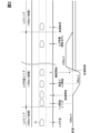
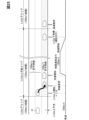
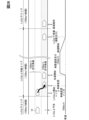
- the road on which the road is traveled is, for example, a highway, and from a road (first road) corresponding to automatic driving level 2 or lower (hereinafter, automatic driving level 2), automatic driving level A case where the road is shifted to a road (second road) capable of automatic driving level 3 or higher (here, automatic driving level 4) and further to a road corresponding to automatic driving level 2 (first road) is taken as an example.
- the road speed limit (first speed limit) corresponding to automatic driving level 2 is, for example, 100 km/h
- the road speed limit (second speed limit) corresponding to automatic driving level 4 is, for example, 120 km/h. /h.
- the vehicle speed on the road corresponding to automatic driving level 2 corresponds to the first vehicle speed of the present disclosure
- the vehicle speed on the road corresponding to automatic driving level 4 corresponds to the second vehicle speed of the present disclosure.
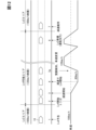
- step S100 (1 in FIG. 2), the control unit 70 determines from various information such as the locator 30, the surroundings monitoring sensor 40, and the in-vehicle communication device 50 that there is no obligation to monitor the surroundings, and the driver can sleep. It is determined whether or not the vehicle is scheduled to travel on a road on which automatic driving level 4 is possible. If an affirmative determination is made in step S100, the control unit 70 proceeds to step S102, and if a negative determination is made, the control ends.
- step S102 the control unit 70 instructs the HCU 160 to issue an advance notice.
- the HCU 160 uses the meter display 120 or the audio device 140, for example, to notify the driver of automatic driving level 4.
- the form of notification is an image (character) or voice, and the content of notification may be, for example, "The vehicle will shift to automatic driving level 4 from now on.”
- step S102 the HCU 160 informs the driver by image and sound that the vehicle speed will be changed from 100 km/h to 80 km/h as the automatic driving level 4 is reached.
- the content of the notification may be, for example, "The vehicle speed will be changed from 100 km/h to 80 km/h in the future.”
- step S104 the control unit 70 determines whether or not the vehicle is traveling on a road capable of automatic driving level 4 without surrounding monitoring obligation. If the control unit 70 makes an affirmative determination in step S104, the process proceeds to step S106, and if a negative determination is made, the process returns to step S102.
- step S106 the control unit 70 determines whether or not there is a trigger for starting automatic driving level 4 by the driver, that is, whether or not there is an input regarding starting automatic driving level 4 using the operation device 60. . If a negative determination is made in step S106, the control unit 70 repeats step S106, and if affirmative determination is made, the process proceeds to step S108.
- step S108 the control unit 70 determines whether or not the driver has given a response (input instruction) to the effect that the second task (smartphone operation, movie viewing, etc.) is to be performed. If the control unit 70 makes an affirmative determination in step S108, it proceeds to step S110, and if it makes a negative determination (continues the obligation to monitor the surroundings), it proceeds to step S112.
- step S110 the control unit 70 performs deceleration control (change from 100 km/h to 80 km/h) and instructs the HCU 160 to notify the driver of the deceleration control.
- the content of the deceleration control notification may be, for example, "Deceleration will start” and "The running speed will be changed from 100 km/h to 80 km/h.”
- step S112 the control unit 70 maintains the vehicle speed (100 km/h) as it is (chain two-dot line in FIG. 2) because the driver does not request the second task.
- step S112 the control unit 70 skips step S114 and proceeds to step S116.
- step S114 the control unit 70 determines whether the deceleration is completed (whether the vehicle speed has reached the deceleration set value of 80 km/h), and if the determination is affirmative, the process proceeds to step S116. If a negative determination is made, step S114 is repeated.
- step S116 the control unit 70 issues an instruction to the HCU 160 to notify the driver that automatic driving level 4, which does not require perimeter monitoring, has become possible.
- the content of the notification may be "The automatic driving level has shifted to level 4. From here, the second task is possible. Sleep is possible.”
- step S118 the control unit 70 determines whether or not the driver among the passengers has fallen asleep from the image data of the passengers captured by the in-vehicle camera 45 at automatic driving level 4. If the determination is affirmative, the process proceeds to step S120, and if the determination is negative, step S118 is repeated.
- step S120 the control unit 70 determines whether or not the second vehicle speed at automatic driving level 4 is lower than the first vehicle speed at automatic driving level 2. If the determination is affirmative, the process proceeds to step S122. If it transfers and a negative determination is carried out, step S120 will be repeated.
- control unit 70 executes acceleration control in step S122 (5 in FIG. 2).
- the content of the acceleration control is to (1) make the second vehicle speed at automatic driving level 4 higher than the first vehicle speed at automatic driving level 2 (120 km/h), or (2) make it equal to the first vehicle speed ( 100 km/h), or (3) lower than the first vehicle speed and higher than the current second vehicle speed (approximately 90 km/h).
- step S124 the control unit 70 changes from the automatic driving level 4, in which there is no obligation to monitor the surroundings and the driver can sleep, to the automatic driving level 2, which has the obligation to monitor the surroundings. Determine if expected. If the determination is affirmative, the control unit 70 proceeds to step S126, and if the determination is negative, the control unit 70 repeats step S124.
- step S126 the control unit 70 instructs the HCU 160 to notify the driver.
- the HCU 160 notifies the driver of the obligation to monitor the surroundings, and also notifies the driver of the change of driving.
- the content of the notification prompting the obligation to monitor the surroundings may be, for example, “Transition to automatic driving level 2. Monitoring of the surroundings is required.”
- the content of the notification for the driver change can be "Please respond to automatic driving level 2.”
- step S130 the control unit 70 determines whether or not the vehicle is traveling on an automated driving level 2 road that has an obligation to monitor the surroundings. If the determination is affirmative, the control unit 70 proceeds to step S132, and if the determination is negative, the control unit 70 repeats steps S126 and S130.
- step S132 the control unit 70 maintains the vehicle speed set by the acceleration control executed in step S122 so as to be equal to or lower than the speed limit on the automatic driving level 2 road.
- the speed is set to 100 km/h.
- the vehicle speed is set to 100 km/h by acceleration control, it is maintained at 100 km/h.
- 90 km/h is maintained.
- acceleration control when it is determined that the driver has fallen asleep in the second automatic driving state, and when the vehicle is traveling at a vehicle speed lower than the first vehicle speed, acceleration control is executed. Therefore, it is possible to change and set the vehicle speed to a higher speed within the speed limit without making the driver uneasy.
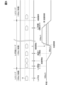
- FIGS. A second embodiment is shown in FIGS.
- the controller 70 executes the first deceleration control in contrast to the first embodiment.
- Step S128 The flowchart of the second embodiment shown in FIG. 6 is obtained by adding step S128 and changing step S132 to step S134 with respect to the flowchart (FIGS. 3 and 4) described in the first embodiment.
- Steps S100 to S116 are the same as in FIG. 3, and are omitted for explanation of the second embodiment, and only shown in FIG.
- control unit 70 executes acceleration control in step S122 (5 in FIG. 5), and then in step S124 (6 in FIG. 5), there is no obligation to monitor the surroundings, and the driver It is determined whether or not a change from automatic driving level 4, which allows the driver to sleep, to automatic driving level 2, which requires surroundings monitoring, is expected.
- step S124 the control unit 70 instructs the HCU 160 to notify the driver in step S126 (6 in FIG. 5).
- the HCU 160 notifies the driver of the obligation to monitor the surroundings, and also notifies the driver of the change of driving.
- step S128 the control unit 70 executes the first deceleration control.
- the vehicle speed for example, 100 km/h
- the first vehicle speed for example, 100 km/h
- step S134 the reduced vehicle speed is maintained by the first deceleration control. do.
- control unit 70 determines from the detection result of the in-vehicle camera 45 (detection unit) that there is a fellow passenger other than the driver as a passenger, at least one of the fellow passengers is in an awake state, it is preferable to prohibit the execution of the acceleration control.
- the vehicle speed (eg, 80 km/h) decelerated toward automatic driving level 4 is maintained and continued to next automatic driving level 2. .
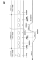
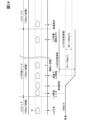
- FIGS. 7 A third embodiment is shown in FIGS.
- the controller 70 executes the second speed reduction control instead of the first speed reduction control in the first embodiment.
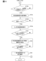
- FIGS. 8 and 9 The flowcharts of the third embodiment shown in FIGS. 8 and 9 have steps S123a to S123e added to the flowcharts (FIGS. 3 and 4) described in the first embodiment, and step S132 is changed to step S136. It has been changed. Steps S100 to S116 are the same as in FIG. 3, and are omitted for explanation of the third embodiment and shown in FIGS. 8 and 9. FIG.
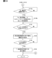
- control unit 70 After executing the acceleration control in step S122 (5 in FIG. 7), the control unit 70, in step S123a (5a in FIG. 7), selects at least It is determined whether or not one person is in an awake state.
- the control unit 70 When the control unit 70 makes an affirmative determination in step S123a, it further executes the second deceleration control in step S123e (5a in FIG. 7).
- the second deceleration control is a control for decelerating the vehicle speed to a predetermined vehicle speed (for example, 100 km/h) if the passenger is awakened after the acceleration control as described above.
- step S136 in FIG. 7
- the control unit 70 changes the vehicle speed at automatic driving level 2 to the predetermined vehicle speed set by the second deceleration control. maintain.
- the awake occupants can relax and view the surrounding scenery.
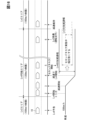
- FIGS. 10 and 11 A fourth embodiment is shown in FIGS. 10 and 11.
- the control unit 70 controls the acceleration control after the driver and at least one fellow passenger are in an awake state.
- the notification unit 105 notifies the driver to select whether or not to perform the second deceleration control for decelerating the vehicle speed after the acceleration control to a predetermined vehicle speed. It is.
- the flowchart of the fourth embodiment shown in FIG. 11 is obtained by changing steps S123a to S123e to steps S123b to S123d in the flowchart (FIGS. 8 and 9) described in the third embodiment.
- Steps S100 to S122 are the same as in FIG. 8, and are omitted for explanation of the fourth embodiment and are shown in FIG.
- control unit 70 After executing acceleration control in step S122 (5 in FIG. 10), the control unit 70 selects the driver, among the passengers, from the image data of the passengers captured by the in-vehicle camera 45 in step S123b (5a in FIG. 10). and whether or not at least one fellow passenger is awake.
- step S123c the notification unit 105 notifies the driver of whether or not to perform the second deceleration control. instruct HCU 160 to do so.
- step S123d when the control unit 70 determines in step S123d that the driver has selected to perform the second deceleration control using the operation device 60, the control unit 70 performs the second deceleration control in step S123e.
- step S136 the control unit 70 changes the vehicle speed at automatic driving level 2 to the predetermined vehicle speed set in the second deceleration control. maintain.
- the driver and at least one passenger are in an awake state after the acceleration control, the driver is made to select execution of the second deceleration control, and the second deceleration control is executed.
- an awake passenger can relax and see the surrounding scenery.
- FIGS. 12 and 13 A fifth embodiment is shown in FIGS. 12 and 13.
- FIG. 12 when the control unit 70 determines that the occupant is awake from the detection result of the in-vehicle camera 45 in the second automatic driving state, the surrounding environment or the occupant The vehicle speed in the second automatic driving state is changed according to the implementation status of the second task.
- steps S118 to S122 are changed to steps S119a to S119b in contrast to the flowchart (FIGS. 3 and 4) described in the first embodiment, and step S132 is replaced by steps S119a and S119b. It is changed to step S138.
- Steps S100 to S116 are the same as in FIG. 3, and are omitted for explanation of the fifth embodiment, and are shown in FIG.
- step S119a the control unit 70 determines whether the occupant is awake from the image data of the occupant captured by the in-vehicle camera 45. determine whether or not
- step S119b the surrounding environment obtained by the surrounding monitoring sensor 40 or the second automatic driving state obtained by the in-vehicle camera 45 is permitted.
- the vehicle speed in the second automatic driving state is changed (acceleration and deceleration) according to the execution status of the second task of the occupant.
- the control unit 70 When changing the vehicle speed, the control unit 70, for example, decelerates in a scenic spot and accelerates in a place other than a scenic spot as the surrounding environment.
- a place other than a scenic spot is a place that is not suitable for viewing the surrounding scenery while driving, for example, an area in a tunnel or an area where soundproof walls are continuously provided on the side of the road.
- the control unit 70 decelerates when the passenger's second task is completed. It should be noted that FIG. 12 shows that the vehicle accelerates immediately after deceleration. Of course it is possible.
- step S138 the control unit 70 maintains the reduced vehicle speed.
- the occupant in addition to the arousal state of the occupant, by changing the vehicle speed in the second automatic driving state according to the surrounding environment during driving or the occupant's execution status of the second task, the occupant can relax without anxiety. Views of the surrounding area can be enjoyed.
- FIG. 14 A sixth embodiment is shown in FIG.
- the control unit 70 changes the acceleration/deceleration range of the set vehicle speed in the second automatic driving state of automatic driving level 4 to the set vehicle speed in the third automatic driving state of automatic driving level 3. It is designed to be wider than the acceleration/deceleration width of
- the acceleration/deceleration range is the range (difference) between the lower limit vehicle speed and the upper limit vehicle speed set for autonomous driving levels 3 and 4.
- the acceleration/deceleration width at automatic driving level 3 is set to the lower limit vehicle speed 80 km/h to the upper limit vehicle speed 100 km/h (difference is 20 km/h)
- the acceleration/deceleration width at automatic driving level 4 is the lower limit vehicle speed 70 km/h. /h to the upper limit vehicle speed of 120 km/h (difference is 50 km/h).
- the lower limit vehicle speed at automatic driving level 4 is lower than the lower limit vehicle speed at automatic driving level 3, and the upper limit vehicle speed at automatic driving level 4 is higher than the upper limit vehicle speed at automatic driving level 3.
- a seventh embodiment is shown in FIG.
- the control unit 70 determines whether the occupant is awake or sleeping based on the detection result of the in-vehicle camera 45 (detection unit). It adjusts the acceleration/deceleration width at level 4 (second automatic operation state).
- the control unit 70 changes the acceleration/deceleration width at automatic driving level 4 to a narrower direction. Note that the changed acceleration/deceleration width at automatic driving level 4 is wider than the acceleration/deceleration width at automatic driving level 3.
- FIG. 16 An eighth embodiment is shown in FIG. In automatic driving level 4 (second automatic driving state), the passenger is permitted to perform the second task.
- the control unit 70 adjusts the acceleration/deceleration width at the automatic driving level 4 according to the occupant's execution status of the second task obtained by the in-vehicle camera 45 (detection unit). It is designed to
- the control unit 70 changes the acceleration/deceleration width at automatic driving level 4 to a narrower direction. Note that the changed acceleration/deceleration width at automatic driving level 4 is wider than the acceleration/deceleration width at automatic driving level 3.
- FIG. 17 A ninth embodiment is shown in FIG.
- the control unit 70 controls whether the occupant is in an awake state or a sleeping state when traveling on a curved road at automatic driving level 4 (second automatic driving state).
- the acceleration/deceleration width is adjusted according to whether the
- the control unit 70 changes the acceleration/deceleration range to a narrower direction. Note that the changed acceleration/deceleration width at automatic driving level 4 is wider than the acceleration/deceleration width at automatic driving level 3.
- FIG. 18 A tenth embodiment is shown in FIG.
- the control unit 70 controls whether the set vehicle speed is the same between automatic driving level 4 (second automatic driving state) and automatic driving level 3 (third automatic driving state).
- the inter-vehicle distance between the own vehicle and the other vehicle is set to be different between the automatic driving level 4 and the automatic driving level 3.
- the inter-vehicle distance includes both the inter-vehicle distance between the preceding vehicle and the host vehicle and the inter-vehicle distance between the following vehicle and the host vehicle.
- control unit 70 sets the inter-vehicle distance at automatic driving level 4 to be wider than the inter-vehicle distance at automatic driving level 3.
- the control unit 70 widens the inter-vehicle distance from the preceding vehicle by temporarily decelerating, and widens the inter-vehicle distance from the following vehicle by temporarily increasing the speed.
- FIG. 19 An eleventh embodiment is shown in FIG.
- the control unit 70 determines whether the occupant is awake or sleeping based on the detection result of the in-vehicle camera 45 (detection unit).
- the inter-vehicle distance at level 4 (second automatic driving state) is set to be different.
- control unit 70 sets the inter-vehicle distance to be narrower when the occupant is sleeping than when the occupant is awake.
- FIG. 20 A twelfth embodiment is shown in FIG.
- the control unit 70 when prompting the occupant from the sleeping state to the awake state, the control unit 70 sets the vehicle-to-vehicle distance to the side that is widened before prompting the awake state. .
- the case where the occupant is urged from the sleeping state to the awake state is, for example, when the destination is being guided by the locator 30 and the occupant is approaching the destination, when an emergency occurs, or when the automatic driving level is lowered to level 2 or lower.
- the HCU 160 urges the occupant to wake up by the sound of the audio device 140, for example, according to the instruction from the control unit 70.
- control unit 70 sets the inter-vehicle distance to be wider than before.
- FIG. 21 A thirteenth embodiment is shown in FIG.
- the control unit 70 when prompting the occupant from the wakeful state to the sleeping state, the control unit 70 sets the inter-vehicle distance to a narrower side after prompting the sleep state. . After confirming the sleep state of the occupant by the in-vehicle camera 45, the control unit 70 sets the vehicle-to-vehicle distance to a narrower side.
- FIG. 22 A fourteenth embodiment is shown in FIG.
- the control unit 70 controls the guidance route by the locator 30 (car navigation device) when traveling on a general road at the automatic driving level 4 (second automatic driving state).
- the upper limit of the set vehicle speed at automatic driving level 4 is limited to a predetermined vehicle speed on the lower side.
- a plurality of consecutive branch points are, for example, right/left turn intersections. Restrict.
- this information is used as a trigger to limit the set vehicle speed to a predetermined vehicle speed after turning at the first intersection.
- the acceleration after turning at the first intersection can be moderated, so that the comfort of the passengers at the next intersection is not hindered.
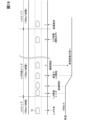
- FIG. 23 shows the fifteenth embodiment.
- the control unit 70 changes from automatic driving level 2 or lower (low automatic driving state) to automatic driving level 3 or higher (high automatic driving state, automatic driving level 3, and level 4). ), the vehicle speed is increased so as to reach the second maximum speed set for the road on which the automatic driving level is 3 or higher. Furthermore, the control unit 70 controls the vehicle speed to be equal to or lower than the first maximum speed set on the road on which the automatic driving level is 2 or lower before the transition from the automatic driving level 3 or higher to the automatic driving level 2 or lower. lower the
- the speed limit (first maximum speed) on the road (area) corresponding to automatic driving level 2 or lower is, for example, 100 km / h
- the speed limit (second maximum speed) is, for example, 120 km/h.
- the vehicle 10 is traveling at, for example, 100 km/h.
- the control unit 70 makes an advance notification regarding the transition to automatic driving level 3 or higher. Furthermore, the control unit 70 enters an area where automatic driving level 3 or higher is possible, and confirms a permission input (start trigger for level 3 or higher) from the driver regarding the start of automatic driving level 3 or higher using the operation device 60 . Then, the control unit 70 starts accelerating the vehicle speed from 100 km/h to 120 km/h, for example, and maintains the vehicle speed when the vehicle speed reaches 120 km/h.
- the control unit 70 reduces the vehicle speed from 120 km/h to 100 km/h or lower (decelerates) before shifting to automatic driving level 2 or lower. Then, the control unit 70 notifies the driver of driving change at automatic driving level 2 or lower, and performs the driving change to the driver.
- the vehicle 10 travels in an area of automatic driving level 2 or lower at a reduced vehicle speed (100 km/h).
- the vehicle is traveling at a constant speed of 100 km/h at Autonomous Driving Level 2 or lower, it may continue to run at 100 km/h at Autonomous Driving Level 3 or higher.
- the vehicle speed is increased in accordance with the speed limit of the road corresponding to automatic driving level 3 or higher, so it is possible to travel at a higher speed.
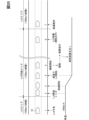
- FIG. 24 shows the sixteenth embodiment.
- the control unit 70 changes from automatic driving level 2 or lower (low automatic driving state) to automatic driving level 3 or higher (high automatic driving state). Yes, once the vehicle shifts to automatic driving level 3 and level 4), it continues to run at the vehicle speed at automatic driving level 2 or lower. Then, when the continuous vehicle speed is lower than the maximum speed set on the road on which the automatic driving level is 3 or higher, the control unit 70 notifies the driver of the maximum speed by the notification unit 105, and the driver When there is an acceleration permission by , the vehicle speed is increased to reach the maximum speed.
- the speed limit on the road (area) corresponding to automatic driving level 2 or lower is, for example, 100 km/h
- the road (possible area) corresponding to automatic driving level 3 or higher ) is, for example, 120 km/h.
- control unit 70 in the stage before shifting from automatic driving level 3 or higher to automatic driving level 2 or lower, limits set on roads traveling at automatic driving level 2 or lower Decrease the vehicle speed so that it is below the speed.
- the driver is notified of the maximum speed (120 km / h) in the area where automatic driving level 3 or higher is possible, and the driver accelerates when there is acceleration permission.
- the speed change (acceleration) will be implemented, and the driver will be able to travel at a higher speed without feeling uneasy.
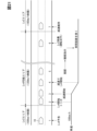
- FIG. 25 shows the seventeenth embodiment.
- the control unit 70 controls the automatic driving level 2 or lower (low automatic driving state), if there is an overpassable lane in which the speed limit can be exceeded, a lane change to the overpassable lane is attempted.
- the speed limit on roads (areas) corresponding to automated driving level 2 or lower is, for example, 100 km/h.
- roads (possible areas) corresponding to automatic driving level 3 or higher have two driving lanes on the left side with respect to the traveling direction of the vehicle 10 and an overtaking lane on the right side.
- the speed limit in the driving lane is, for example, 100 km/h
- the speed limit in the passing lane is, for example, 120 km/h.
- the vehicle 10 is traveling at, for example, 100 km/h.
- the control unit 70 changes lanes to an overtaking lane with a speed limit of 120 km/h when entering a lane with a speed limit of 100 km/h in a possible area with an automatic driving level of 3 or higher from an area with an automatic driving level of 2 or lower. Note that the vehicle 10 may not be able to change lanes depending on the running conditions of other vehicles in the overtaking lane.
- the control unit 70 starts accelerating the vehicle speed from 100 km/h to 120 km/h, and when the vehicle speed reaches 120 km/h, the vehicle speed is maintained. do.
- the control unit 70 when an area of automatic driving level 2 or lower approaches, the control unit 70 reduces the vehicle speed from 120 km/h to 100 km/h or lower before shifting to automatic driving level 2 or lower. (deceleration). Then, the control unit 70 notifies the driver of driving change at automatic driving level 2 or lower, and performs the driving change to the driver.
- the vehicle 10 travels in an area of automatic driving level 2 or lower at a reduced vehicle speed (100 km/h).
- the control unit 70 further causes the notification unit 105 to notify the lane change when it is possible to enter the overtaking lane. , the driver is notified, and lane change is performed when there is a lane change permission (trigger) from the driver.
- the control unit 70 determines whether other vehicles are running in the passing lane, that is, whether or not there is an empty space in the passing lane for lane change, and if there is a space, the driver is notified and the lane change is permitted. The lane change is performed after taking the
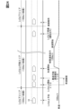
- FIG. 27 shows the eighteenth embodiment.
- the control unit 70 implements speed regulation according to the driving environment in a possible area (highly automated driving area) that enables automated driving level 3 or higher (highly automated driving state). If so, the notification unit 105 notifies the driver of the restricted speed, and if the driver gives permission to decelerate, the vehicle is decelerated to the restricted speed.
- FIG. 27 shows an example in which the original speed limit of 120 km/h is regulated to a speed limit of 50 km/h in an area where automatic driving level 3 or higher is possible.
- control unit 70 determines the speed change rate during deceleration when decelerating to the regulated speed of 50 km/h, for example, as in the fifteenth to seventeenth embodiments, from the speed change rate during acceleration when acceleration is assumed. is also set small (slope of change is gradual).
- control unit 70 notifies the driver of driving change at automatic driving level 2 or lower, and transfers driving to the driver.
- the vehicle speed is increased to the speed limit in the area of automatic driving level 2 or lower.
- the vehicle speed difference with the following vehicle that is not automatically driving will increase. As it grows (becomes abruptly approaching), the degree of danger increases.
- the driver is notified of the restricted speed by the notification unit 105, and if the driver gives permission to decelerate, the vehicle will decelerate to reach the restricted speed. It is possible to suppress the occurrence of a sudden approach to the following vehicle.
- the rate of change in speed during deceleration is set to be smaller than the rate of change in speed during acceleration when acceleration is assumed, it is possible to further suppress rapid approach with the following vehicle. Also, the acceleration that occurs in the driver during deceleration can be moderated.
- FIG. 28 A modification of the eighteenth embodiment is shown in FIG.
- the control unit 70 notifies the driver of the speed limit by the notifying unit 105, and then a predetermined time elapses. However, if there is no deceleration permission, deceleration to the regulated speed is forcibly executed without deceleration permission.
- the notification unit 105 is the meter display 120 and the audio device 140 , but the notification unit 105 may be another HUD 110 or CID 130 without being limited thereto.
- the CID 130 can realize a display related to automatic operation and an operation (touch operation) to switch to automatic operation.
- the CID 130 may be formed of, for example, a plurality of CIDs, and the meter display 120 and the plurality of CIDs may be a pillar-to-pillar type notification unit 105 arranged in a horizontal row on the instrument panel.
- the disclosure in this specification, drawings, etc. is not limited to the illustrated embodiments.
- the disclosure encompasses the illustrated embodiments and variations thereon by those skilled in the art.
- the disclosure is not limited to the combinations of parts and/or elements shown in the embodiments.
- the disclosure can be implemented in various combinations.
- the disclosure can have additional parts that can be added to the embodiments.
- the disclosure encompasses omitting parts and/or elements of the embodiments.
- the disclosure encompasses permutations or combinations of parts and/or elements between one embodiment and another.
- the disclosed technical scope is not limited to the description of the embodiments.
- the disclosed technical scope is indicated by the description of the claims, and should be understood to include all changes within the meaning and range of equivalents to the description of the claims.
- the controller 70, HCU 160, and techniques described in this disclosure are provided by configuring a processor and memory programmed to perform one or more functions embodied by a computer program. It may be implemented by a computer.
- controller 70, HCU 160 and techniques described in this disclosure may be implemented by a dedicated computer provided by configuring the processor with one or more dedicated hardware logic circuits.
- controller 70, HCU 160, and techniques described in this disclosure may be implemented by a processor and memory programmed to perform one or more functions and a processor configured by one or more hardware logic circuits. may be implemented by one or more dedicated computers configured in combination with
- the computer program may be stored in a computer-readable non-transitional tangible recording medium as instructions executed by a computer.
- each section is expressed as S100, for example. Further, each section can be divided into multiple subsections, while multiple sections can be combined into a single section. Each section thus configured may also be referred to as a device, module or means.
- a vehicle control device comprising a control unit (70) that controls switching between a second automatic driving state of driving level 4 or higher, A detection unit (45) for detecting the condition of the occupant of the vehicle, In the second automatic driving state, when it is determined from the detection result of the detecting unit that the driver among the occupants has fallen asleep, the control unit sets the second vehicle speed in the second automatic driving state to higher than the first vehicle speed in the first automatic driving state, Alternatively, equal to the first vehicle speed, Alternatively, a vehicle control device that executes acceleration control to make the vehicle speed lower than the first vehicle speed and higher than the current second vehicle speed.
- the control unit After executing the acceleration control, the control unit decelerates the vehicle speed after the acceleration control to a predetermined vehicle speed when it is determined from the detection result of the detection unit that at least one of the occupants is in an awake state.
- a vehicle control device according to any one of technical ideas 1 to 3 for executing deceleration control.
- a vehicle control device comprising a control unit (70) that controls switching between a second automatic driving state of driving level 4 or higher, a detection unit (45) for detecting the condition of a vehicle occupant; an autonomous sensor (40) for sensing the surrounding environment of the vehicle; In the second automatic driving state, when the occupant is determined to be in an awake state from the detection result of the detecting unit, the surrounding environment obtained by the autonomous sensor or the second automatic driving state obtained by the detecting unit A vehicle control device that changes the vehicle speed in the second automatic driving state according to the execution status of the passenger's second task permitted by the second automatic driving state.
- a vehicle control device comprising a control unit (70) that performs switching control between a second automatic driving state of driving level 4 or higher and a third automatic driving state of automatic driving level 3 without obligation to monitor surroundings,
- the control unit is a vehicle control device that widens the acceleration/deceleration range of the set vehicle speed in the second automatic operation state than the acceleration/deceleration range of the set vehicle speed in the third automatic operation state.
- the control unit adjusts the acceleration/deceleration width in the second automatic driving state according to whether the occupant is in an awake state or a sleeping state from the detection result of the detection unit.
- Technical idea 10 for adjusting the acceleration/deceleration range according to whether the occupant is in an awake state or in a sleep state when traveling on a curved road in the second automatic driving state.
- Vehicle controller for adjusting the acceleration/deceleration range according to whether the occupant is in an awake state or in a sleep state when traveling on a curved road in the second automatic driving state.
- a vehicle control device comprising a control unit (70) that performs switching control between a second automatic driving state of driving level 4 or higher and a third automatic driving state of automatic driving level 3 without obligation to monitor surroundings, Even if the set vehicle speed is the same in the second automatic driving state and the third automatic driving state, the control unit adjusts the following distance between the own vehicle and the other vehicle in the second automatic driving state and the third automatic driving state.
- Vehicle controllers that set different
- a detection unit (45) for detecting the condition of the occupant of the vehicle According to technical idea 14, the control unit sets the inter-vehicle distance in the second automatic driving state differently depending on whether the occupant is in an awake state or a sleeping state from the detection result of the detection unit. Vehicle controller.
- the control unit When traveling on a general road in the second automatic driving state, the control unit sets the upper limit of the set vehicle speed in the second automatic driving state to a low side when there are a plurality of consecutive branch points on the route guided by the car navigation device. 19.
- the vehicle control device according to any one of technical ideas 10 to 19, wherein the vehicle speed is limited to a predetermined vehicle speed.
- the fork is a right/left turn intersection, 21.
- a vehicle control device comprising a control unit (70) for switching and controlling an automatic driving state, The control unit After shifting from the low-autonomous driving state to the high-autonomous driving state, the vehicle speed is increased so as to reach the second maximum speed set on the road on which the vehicle travels in the high-automatic driving state, A vehicle control device that reduces the vehicle speed to a first maximum speed or less set on a road on which the vehicle travels in the low-automatic driving state before shifting from the high-automatic driving state to the low-automatic driving state.
- a vehicle control device comprising a control unit (70) for switching and controlling an automatic driving state, A notification unit (105) that notifies information about automatic driving,
- the control unit shifts from the low-autonomous driving state to the high-autonomous driving state, the control unit continues driving at the vehicle speed in the low-automatic driving state, and the continued vehicle speed is higher than the maximum speed set for the road on which the high-automatic driving state is running. If the maximum speed is low, the vehicle control device notifies the driver of the maximum speed by means of a notification unit, and increases the vehicle speed to reach the maximum speed when the driver permits acceleration.
- a vehicle control device comprising a control unit (70) for switching and controlling an automatic driving state, In a high-automation area where high-autonomous driving is possible, the control unit attempts to change lanes to the lanes where the vehicle can exceed the speed limit in low-autonomous driving if there are lanes that allow the vehicle to exceed the speed limit.
- Vehicle controller In a high-automation area where high-autonomous driving is possible, the control unit attempts to change lanes to the lanes where the vehicle can exceed the speed limit in low-autonomous driving if there are lanes that allow the vehicle to exceed the speed limit.
- a vehicle control device comprising a control unit (70) for switching and controlling an automatic driving state, A notification unit (105) that notifies information about automatic driving, The control unit notifies the driver of the restricted speed by means of the notification unit and permits the driver to decelerate when speed restrictions are being enforced due to the driving environment in a highly automated area that enables a highly automated driving state. Vehicle control device that decelerates to the regulated speed when there is
Abstract
車両(10)の自動運転を実行するにあたって、走行する道路に応じて、手動または周辺監視義務を伴う自動運転レベル(2)以下の第1自動運転状態と、周辺監視義務がなく睡眠が許容される自動運転レベル(4)以上の第2自動運転状態とを切替え制御する制御部(70)を備える車両制御装置であって、車両の乗員の状況を検出する検出部(45)を備え、制御部は、第2自動運転状態において、検出部の検出結果から、乗員のうち、運転者が睡眠状態となったと判定した場合、第2自動運転状態における第2車速を、第1自動運転状態における第1車速よりも高くする、あるいは、第1車速と同等にする、あるいは、第1車速よりも低く、かつ現在の第2車速よりも高くする加速制御を実行する。
Description
この出願は、2021年11月15日に日本に出願された特許出願第2021-185883号、および、2022年5月30日に日本に出願された特許出願第2022-087901号、および2022年8月1日に日本出願された特許出願第2022-122747号を基礎としており、基礎の出願の内容を、全体的に、参照により援用している。
本開示は、車両制御装置に関するものである。
車両制御装置として、例えば、特許文献1に記載されたものが知られている。特許文献1の車両制御装置(運転交代制御装置)では、自動運転可能エリアから手動運転エリアに移行する際に、運転交代をする前に、切替え区間を設けて、運転負荷(例えば速度)を下げるようにしている。これにより、自動運転から手動運転への運転交代にあたって、運転者の不安を軽減するようにしている。
自動運転では、周辺監視義務の伴わない自動運転レベル3~レベル5の区分けが想定されている。更に、自動運転レベル4、レベル5では、運転者の睡眠(仮眠)が許可される想定となっている。
自動運転レベル4以上では、周辺監視義務を伴わないことから、自動運転中であっても、設定車速が相対的に高い側に変更されると、運転者は不安を感じる可能性がある。一方、自動運転中に運転者が寝ている場合では、車速設定が相対的に高い側に変更されたとしても、不安を感じることはない。尚、同乗者についても同様である。
本開示の目的は、上記問題に鑑み、自動運転レベル4以上において、乗員の覚醒状態に応じて、不安を低減して、適切な速度設定を可能とする車両制御装置を提供することにある。加えて、本開示の他の目的は、自動運転レベル4以上において、適切な速度設定、あるいは適切な車間距離の設定を可能とする車両制御装置を提供することにある。本開示の他の目的は、自動運転レベル3以上において、適切な速度設定、あるいは適切な車間距離の設定を可能とする車両制御装置を提供することにある。
第1の開示では、車両の自動運転を実行するにあたって、走行する道路に応じて、手動または周辺監視義務を伴う自動運転レベル2以下の第1自動運転状態と、周辺監視義務がなく睡眠が許容される自動運転レベル4以上の第2自動運転状態とを切替え制御する制御部を備える車両制御装置であって、
車両の乗員の状況を検出する検出部を備え、
制御部は、第2自動運転状態において、検出部の検出結果から、乗員のうち、運転者が睡眠状態となったと判定した場合、第2自動運転状態における第2車速を、
第1自動運転状態における第1車速よりも高くする、
あるいは、第1車速と同等にする、
あるいは、第1車速よりも低く、かつ現在の第2車速よりも高くする加速制御を実行する。
車両の乗員の状況を検出する検出部を備え、
制御部は、第2自動運転状態において、検出部の検出結果から、乗員のうち、運転者が睡眠状態となったと判定した場合、第2自動運転状態における第2車速を、
第1自動運転状態における第1車速よりも高くする、
あるいは、第1車速と同等にする、
あるいは、第1車速よりも低く、かつ現在の第2車速よりも高くする加速制御を実行する。
第1の開示によれば、第2自動運転状態において、運転者が睡眠状態となったと判定した場合に、加速制御を実行するので、運転者に不安を与えることなく、制限速度内で車速を高い側に変更設定することができる。
自動運転中においては、乗員の覚醒状態に加えて、走行中の周辺状況、あるいはセカンドタスクの実施状況に応じても適切な車速の設定が望まれる。
第2の開示では、車両の自動運転を実行するにあたって、走行する道路に応じて、手動または周辺監視義務を伴う自動運転レベル2以下の第1自動運転状態と、周辺監視義務がなく睡眠が許容される自動運転レベル4以上の第2自動運転状態とを切替え制御する制御部を備える車両制御装置であって、
車両の乗員の状況を検出する検出部と、
車両の周辺環境を検知する自律センサと、を備え、
制御部は、第2自動運転状態において、検出部の検出結果から、乗員が覚醒状態であると判定した場合、自律センサによって得られる周辺環境、あるいは、検出部によって得られる第2自動運転状態にて許可される乗員のセカンドタスクの実施状況に応じて、第2自動運転状態における車速を変化させる。
車両の乗員の状況を検出する検出部と、
車両の周辺環境を検知する自律センサと、を備え、
制御部は、第2自動運転状態において、検出部の検出結果から、乗員が覚醒状態であると判定した場合、自律センサによって得られる周辺環境、あるいは、検出部によって得られる第2自動運転状態にて許可される乗員のセカンドタスクの実施状況に応じて、第2自動運転状態における車速を変化させる。
第2の開示によれば、乗員の覚醒状態に加えて、走行中の周辺環境、あるいは乗員のセカンドタスクの実施状況に応じて、第2自動運転状態における車速を変更することで、乗員は、不安なく、ゆったりと周辺の景色を眺めることができる。
第3の開示では、車両の自動運転を実行するにあたって、走行する道路に応じて、手動または周辺監視義務を伴う自動運転レベル2以下の第1自動運転状態と、周辺監視義務がなく睡眠が許容される自動運転レベル4以上の第2自動運転状態と、周辺監視義務のない自動運転レベル3の第3自動運転状態と、を切替え制御する制御部を備える車両制御装置であって、
制御部は、第2自動運転状態における設定車速の加減速幅を、第3自動運転状態における設定車速の加減速幅よりも広くする。
制御部は、第2自動運転状態における設定車速の加減速幅を、第3自動運転状態における設定車速の加減速幅よりも広くする。
第3の開示によれば、第3自動運転状態に対して第2自動運転状態において、設定車速の加減速幅を広くすることで、臨機応変に設定速度を変更することが可能となり、スムーズな走行が可能となる。
第4の開示では、車両の自動運転を実行するにあたって、走行する道路に応じて、手動または周辺監視義務を伴う自動運転レベル2以下の第1自動運転状態と、周辺監視義務がなく睡眠が許容される自動運転レベル4以上の第2自動運転状態と、周辺監視義務のない自動運転レベル3の第3自動運転状態と、を切替え制御する制御部を備える車両制御装置であって、
制御部は、第2自動運転状態と第3自動運転状態とで、設定車速が同一であっても、第2自動運転状態と第3自動運転状態とで、自車両と他車両との車間距離が異なるように設定する。
制御部は、第2自動運転状態と第3自動運転状態とで、設定車速が同一であっても、第2自動運転状態と第3自動運転状態とで、自車両と他車両との車間距離が異なるように設定する。
第4の開示によれば、第3自動運転状態に対して第2自動運転状態の方が、臨機応変に車間距離を変更することが可能となり、スムーズな走行が可能となる。
第5の開示では、車両の自動運転を実行するにあたって、走行する道路に応じて、手動または周辺監視義務を伴う自動運転レベル2以下の低自動運転状態と、周辺監視義務のない自動運転レベル3以上の高自動運転状態と、を切替え制御する制御部を備える車両制御装置であって、
制御部は、
低自動運転状態から高自動運転状態に移行した後に、高自動運転状態にて走行する道路にて設定される第2最高速度となるように車速を上げると共に、
高自動運転状態から低自動運転状態に移行する前段階で、低自動運転状態にて走行する道路にて設定される第1最高速度以下となるように車速を下げる。
制御部は、
低自動運転状態から高自動運転状態に移行した後に、高自動運転状態にて走行する道路にて設定される第2最高速度となるように車速を上げると共に、
高自動運転状態から低自動運転状態に移行する前段階で、低自動運転状態にて走行する道路にて設定される第1最高速度以下となるように車速を下げる。
第5の開示によれば、高自動運転状態で走行する道路の制限速度に合わせて、車速が上げられるので、より速い速度での走行が可能となる。また、高自動運転状態から再び低自動運転状態に移行する際は、事前に車速が低自動運転状態に対応した道路の制限速度に下げられるので、スムーズに移行することが可能となる。
第6の開示では、車両の自動運転を実行するにあたって、走行する道路に応じて、手動または周辺監視義務を伴う自動運転レベル2以下の低自動運転状態と、周辺監視義務のない自動運転レベル3以上の高自動運転状態と、を切替え制御する制御部を備える車両制御装置であって、
自動運転に関する情報を報知する報知部を備え、
制御部は、低自動運転状態から高自動運転状態に移行すると、低自動運転状態における車速での走行を継続し、継続した車速が高自動運転状態で走行する道路にて設定される最高速度よりも低い場合は、最高速度を報知部によって、運転者に対して報知し、運転者による加速許可があると、最高速度となるように車速を上げる。
自動運転に関する情報を報知する報知部を備え、
制御部は、低自動運転状態から高自動運転状態に移行すると、低自動運転状態における車速での走行を継続し、継続した車速が高自動運転状態で走行する道路にて設定される最高速度よりも低い場合は、最高速度を報知部によって、運転者に対して報知し、運転者による加速許可があると、最高速度となるように車速を上げる。
第6の開示によれば、高自動運転状態の可能エリアでの最高速度が運転者に報知され、運転者による加速許可があると加速するようにしているので、運転者が認識したうえでの速度変更(加速)が実施されることになり、運転者が不安を覚えることがなく、より速い速度での走行が可能となる。
第7の開示では、車両の自動運転を実行するにあたって、走行する道路に応じて、手動または周辺監視義務を伴う自動運転レベル2以下の低自動運転状態と、周辺監視義務のない自動運転レベル3以上の高自動運転状態と、を切替え制御する制御部を備える車両制御装置であって、
制御部は、高自動運転状態を可能とする高自動エリアにおいて、低自動運転状態の場合に対して、制限速度の超過が可能な超過可能車線が存在すると、超過可能車線への車線変更を試みる。
制御部は、高自動運転状態を可能とする高自動エリアにおいて、低自動運転状態の場合に対して、制限速度の超過が可能な超過可能車線が存在すると、超過可能車線への車線変更を試みる。
第7の開示によれば、車線変更が可能であると、車速を上げることが可能となり、より速い速度での走行が可能となる。
第8の開示では、車両の自動運転を実行するにあたって、走行する道路に応じて、手動または周辺監視義務を伴う自動運転レベル2以下の低自動運転状態と、周辺監視義務のない自動運転レベル3以上の高自動運転状態と、を切替え制御する制御部を備える車両制御装置であって、
自動運転に関する情報を報知する報知部を備え、
制御部は、高自動運転状態を可能とする高自動エリアにおいて、走行環境に伴う速度規制が実施されていると、規制速度を報知部によって、運転者に対して報知し、運転者による減速許可があると、規制速度に減速する。
自動運転に関する情報を報知する報知部を備え、
制御部は、高自動運転状態を可能とする高自動エリアにおいて、走行環境に伴う速度規制が実施されていると、規制速度を報知部によって、運転者に対して報知し、運転者による減速許可があると、規制速度に減速する。
第8の開示によれば、走行環境により速度規制があると、規制速度が報知部によって運転者に対して報知され、運転者による減速許可があると、規制速度に至るように減速するので、減速に伴う後続車両への急接近が発生することを抑制することができる。
以下に、図面を参照しながら本開示を実施するための複数の形態を説明する。各形態において先行する形態で説明した事項に対応する部分には同一の参照符号を付して重複する説明を省略する場合がある。各形態において構成の一部のみを説明している場合は、構成の他の部分については先行して説明した他の形態を適用することができる。各実施形態で具体的に組み合わせが可能であることを明示している部分同士の組み合わせばかりではなく、特に組み合わせに支障が生じなければ、明示していなくても実施形態同士を部分的に組み合せることも可能である。
(第1実施形態)
第1実施形態の車両制御装置100について、図1~図4を参照しながら説明する。車両制御装置100は、車両10の自動運転にかかる制御を実行する装置であり、走行する道路に応じて、手動または周辺監視義務を伴う自動運転レベル2以下の第1自動運転状態と、周辺監視義務がなく(自動運転レベル3以上)睡眠が許容される自動運転レベル4以上の第2自動運転状態とを切替え制御する。車両制御装置100は、ロケータ30、周辺監視センサ40、車内カメラ45、車載通信器50、操作デバイス60、制御部70、および車両制御ECU80等が、通信バス90を介して接続されることで形成されている。
第1実施形態の車両制御装置100について、図1~図4を参照しながら説明する。車両制御装置100は、車両10の自動運転にかかる制御を実行する装置であり、走行する道路に応じて、手動または周辺監視義務を伴う自動運転レベル2以下の第1自動運転状態と、周辺監視義務がなく(自動運転レベル3以上)睡眠が許容される自動運転レベル4以上の第2自動運転状態とを切替え制御する。車両制御装置100は、ロケータ30、周辺監視センサ40、車内カメラ45、車載通信器50、操作デバイス60、制御部70、および車両制御ECU80等が、通信バス90を介して接続されることで形成されている。
また、車両制御装置100には、車両用報知装置101が設けられている。車両用報知装置101は、後述する複数の表示デバイス(各種ディスプレイ110~130)を用いて、例えば、車速、エンジン回転数、トランスミッションのシフト位置、更には、ナビゲーションシステム(ここでは、ロケータ30)によるナビゲーション情報等の車両走行情報を画像等によってドライバ(運転者)に報知(表示)する。あるいは、車両用報知装置101は、オーディオ装置140を用いて、上記車両走行情報を音声によってドライバに報知する。更に、車両用報知装置101は、上記の自動運転が実行される際に、自動運転に関する情報をドライバに報知する。車両用報知装置101は、報知部105、およびHCU(Human Machine Interface Control Unit)160等を備えている。
車両用報知装置101は、通信バス90等を介して、ロケータ30、周辺監視センサ40、車内カメラ45、車載通信器50、制御部70、および車両制御ECU80と、接続されている。また、車両用報知装置101は、操作デバイス60と接続されている。
まず、車両制御装置100の構成について説明する。
ロケータ30は、ナビゲーションシステムを形成するものであり、複数の取得情報を組み合わせる複合測位により、自車位置情報(位置情報)等を生成する。ロケータ30は、GNSS(Global Navigation Satellite System)受信機31、慣性センサ32、高精度地図データベース(以下、「地図DB」)33、およびロケータECU34等を備えている。
GNSS受信機31は、複数の測位衛星からの測位信号を受信する。
慣性センサ32は、車両10に作用する慣性力を検出するセンサである。慣性センサ32は、例えばジャイロセンサおよび加速度センサを備える。
地図DB33は、不揮発性メモリであって、リンクデータ、ノードデータ、道路形状、構造物等の地図データを格納している。地図データは、道路形状および構造物の特徴点の点群からなる3次元地図であってもよい。尚、3次元地図は、REM(Road Experience Management)によって撮像画像をもとに生成されたものであってもよい。また、地図データには、交通規制情報、道路工事情報、気象情報、および信号情報等が含まれていてもよい。地図DB33に格納された地図データは、後述の車載通信器50にて受信される最新の情報に基づいて、定期的または随時に更新される。
ロケータECU34は、プロセッサ、メモリ、入出力インターフェース、およびこれらを接続するバス等を備えたマイクロコンピュータを主体として含む構成である。ロケータECU34は、GNSS受信機31で受信する測位信号、慣性センサ32の計測結果、および地図DB33の地図データを組み合わせることにより、車両10の位置(以下、自車位置)を逐次測位する。
自車位置は、例えば緯度経度の座標で表される構成とすればよい。尚、自車位置の測位には、車両10に搭載された車載センサ81(車速センサ等)から逐次出力される信号から求めた走行距離を用いる構成としてもよい。地図データとして、道路形状および構造物の特徴点の点群からなる3次元地図を用いる場合、ロケータECU34は、GNSS受信機31を用いずに、この3次元地図と、周辺監視センサ40での検出結果とを用いて、自車位置を特定する構成としてもよい。
周辺監視センサ40は、車両10の周辺環境を監視(検知)する自律センサである。周辺監視センサ40は、車両10の周囲の検出範囲から、例えば、歩行者、サイクリスト、人間以外の動物、および他車両(前方車、後続車)等の移動物体、また、路上の落下物、ガードレール、縁石、道路標識、また、道路種別(一般道路、高速道路、アウトバーン等)、車線、車線幅、走行区画線、中央分離帯等の路面表示、更に、道路脇の構造物等の静止物体、景勝地、トンネル、および天候情報などを検出可能である。周辺監視センサ40は、景勝地については、ロケータ30の地図DB33を用いて、検知するようにしてもよい。
周辺監視センサ40は、車両10の周囲の物体を検出した検出情報を、通信バス90を通じて、制御部70に提供する。周辺監視センサ40は、物体検出のための検出構成として、例えば、カメラ41、およびミリ波レーダ42等を有している。
カメラ41は、フロントカメラおよびリアカメラを有している。フロントカメラは、車両10の前方範囲(前方エリア)を撮影した撮像データ、および撮像データの解析結果の少なくとも一方を、検出情報として出力する。同様に、リアカメラは、車両10の後方範囲(後方エリア)を撮影した撮像データ、および撮像データの解析結果の少なくとも一方を、検出情報として出力する。
ミリ波レーダ42は、例えば、車両10の前後の各バンパーに互いに間隔を開けて複数配置されている。ミリ波レーダ42は、ミリ波または準ミリ波を、車両10の前方範囲、前側方範囲、後方範囲および後側方範囲等へ向けて照射する。ミリ波レーダ42は、移動物体および静止物体等で反射された反射波を受信する処理により、検出情報を生成する。尚、地物の特徴点の点群を検出するLiDAR(Light Detection and Ranging/Laser Imaging Detection and Ranging)、超音波の反射波を受信するソナー等の他の検出構成が、周辺監視センサ40に含まれていてもよい。
車内カメラ45は、乗員(ドライバおよび同乗者)の状況を検出する検出部である。乗員の状況は、乗員の覚醒あるいは睡眠の状態、乗員の視線方向、乗員の着座位置、乗員の姿勢(行動)等を含む。
車内カメラ45は、例えば、CCDカメラ、CMOSカメラ、あるいは赤外線カメラ等が使用されて、車両10の天井部前方に設けられている。車内カメラ45は、乗員の顔、上半身等の画像を取得し、取得した画像データを、通信バス90を通じて、制御部70(第2自動運転ECU70B)に提供する。
車載通信器50は、車両10に搭載される通信モジュールである。車載通信器50は、LTE(Long Term Evolution)および5G等の通信規格に沿ったV2N(Vehicle to cellular Network)通信の機能を少なくとも有しており、車両10の周囲の基地局等との間で電波を送受信する。車載通信器50は、路車間(Vehicle to roadside Infrastructure,以下「V2I」)通信、および車車間(Vehicle to Vehicle,以下「V2V」)通信等の機能を更に有していてもよい。車載通信器50は、V2N通信により、クラウドと車載システムとの連携(Cloud to Car)を可能にする。車載通信器50の搭載により、車両10は、インターネットに接続可能なコネクテッドカーとなる。
車載通信器50は、例えば、VICS(Vehicle information and communication System 登録商標)を用いることによって、FM多重放送や道路に設けられたビーコンから、道路上の渋滞状況や交通規制等の道路交通情報を取得する。
また、車載通信器50は、例えば、DCM(Data Communication Module)、あるいは車車間通信を用いることによって、所定のセンタ基地局を介して、あるいは車車間で、複数の前方車、および後続車との通信を行う。そして、車載通信器50は、車両10の前方側、および後方側を走行する他車両の車速、位置、更には自動運転の実行状況等の情報を入手する。
車載通信器50は、VICSやDCMに基づく他車両の情報(周辺情報)を制御部70、およびHCU160等に提供する。
操作デバイス60は、ドライバ等によるユーザ操作を受け付ける入力部である。操作デバイス60には、例えば自動運転機能の各レベルの開始および停止に関連するユーザ操作等が入力される。操作デバイス60には、例えば、ステアリングホイールのスポーク部に設けられたステアスイッチ、ステアリングコラム部に設けられた操作レバー、ドライバの発話内容を認識する音声入力装置、およびセンタインフォメーションディスプレイ130におけるタッチ操作用のアイコン(スイッチ)等が含まれる。操作デバイス60で入力された入力信号は、HCU160を介して制御部70に出力される。尚、操作デバイス60の入力項目として、後述するセカンドタスクの要求有無を含む。
制御部70は、第1自動運転ECU70A、および第2自動運転ECU70Bを有している。第1自動運転ECU70A、および第2自動運転ECU70Bは、それぞれメモリ70A1、70B1、プロセッサ70A2、70B2、入出力インターフェース、およびこれらを接続するバス等を備えたコンピュータを主体として含む構成である。第1自動運転ECU70A、および第2自動運転ECU70Bは、車両10の走行を部分的または実質全て制御する自動走行制御を実行可能なECUである。
第1自動運転ECU70Aは、ドライバの運転操作を部分的に代行する部分的自動運転機能(第1自動運転状態)を備えている。一例として、米国自動車技術会の規定する自動運転レベルにおいて、第1自動運転ECU70Aは、手動または周辺監視義務を伴うレベル2以下の部分的な自動走行制御(運転支援)を可能にする。
第1自動運転ECU70Aは、メモリ70A1に記憶された運転支援プログラムが、複数の命令をプロセッサ70A2に実行させることで、上記の運転支援を実現する複数の機能部を構築する。
第1自動運転ECU70Aは、周辺監視センサ40から取得する検出情報に基づき、車両10の周囲の走行環境を認識する。一例として、第1自動運転ECU70Aは、車両10が現在走行する車線(以下、現在車線)の左右の区画線または道路端の相対位置および形状を示す情報(車線情報)を、解析済みの検出情報として生成する。加えて、第1自動運転ECU70Aは、現在車線にて車両10に先行する前方車(他車両)の有無と、前方車が有る場合のその位置および速度と、を示す情報(前方車情報)を、解析済みの検出情報として生成する。
第1自動運転ECU70Aは、前方車情報に基づいて、目標速度での車両10の定速走行、または先行車への追従走行を実現するACC(Adaptive Cruise Control)制御を実行する。第1自動運転ECU70Aは、車線情報に基づいて、車両10の車線内走行を維持するLTA(Lane Tracing Assist)制御を実行する。具体的には、第1自動運転ECU70Aは、加減速または舵角の制御指令を生成し、後述する車両制御ECU80へと逐次提供する。ACC制御が縦方向制御の一例であり、LTA制御が横方向制御の一例である。
第1自動運転ECU70Aは、ACC制御およびLTA制御の両方を実行することで、レベル2以下の自動運転を実現する。尚、第1自動運転ECU70Aは、ACC制御およびLTA制御のいずれか一方を実行することで、レベル1の自動運転を実現可能であってもよい。
一方、第2自動運転ECU70Bは、ドライバの運転操作を代行可能な自動運転機能(第2自動運転状態)を備えている。第2自動運転ECU70Bは、上記の自動運転レベルにおいて、レベル3以上の自動走行制御(自動運転)を可能にする。すなわち、第2自動運転ECU70Bは、周辺監視の中断がドライバに許可される(周辺監視義務のない)自動運転を実施可能にする。換言すると、第2自動運転ECU70Bは、セカンドタスクが許可される自動運転を実施可能にする。
セカンドタスクとは、ドライバに対して許可される運転以外の行為であって、予め規定された特定行為である。セカンドタスクとしては、例えば、自動運転レベル3以上におけるスマートフォンの操作、センタインフォメーションディスプレイ130における映画鑑賞、読書、他の乗員との会話等、更には、自動運転レベル4以上における睡眠(仮眠)等が挙げられる。つまり、第2自動運転ECU70Bは、自動運転レベル4以上においては、走行中であっても、ドライバの睡眠(仮眠)を実施可能にする(許容する)。
第2自動運転ECU70Bは、メモリ70B1に記憶された自動運転プログラムが、複数の命令をプロセッサ70B2に実行させることで、上記の自動運転を実現する複数の機能部を構築する。
第2自動運転ECU70Bは、ロケータECU34から取得する自車位置および地図データ、周辺監視センサ40から取得する検出情報(周辺環境)、車載通信器50から取得する通信情報等に基づき、車両10の周囲の走行環境を認識する。例えば、第2自動運転ECU70Bは、車両10の現在車線の位置、現在車線の形状、並びに車両10周辺の移動体(他車両)の相対位置および相対速度、渋滞状況等を認識する。
加えて、第2自動運転ECU70Bは、車両10の走行地域における手動運転エリア(MDエリア)および自動運転エリア(ADエリア)の判別、ADエリアにおける非ST区間およびST区間の判別を行い、その認識結果を後述のHCU160に逐次提供する。
MDエリアは、自動運転が禁止されるエリアである。換言すれば、MDエリアは、車両10の縦方向制御、横方向制御および周辺監視の全てをドライバが実行すると規定されたエリアである。例えば、MDエリアは、走行路が一般道路であるエリアとされる。
ADエリアは、自動運転が許可されるエリアである。換言すれば、ADエリアは、縦方向(前後方向)制御、横方向(幅方向)制御および周辺監視のうち1つ以上を、車両10が代替可能なエリアである。例えば、ADエリアは、走行路が高速道路または自動車専用道路であるエリアとされる。
ADエリアは、レベル2以下の自動運転が可能な非ST区間と、レベル3以上の自動運転が可能なST区間とに区分される。尚、本実施形態において、レベル1の自動運転が許可される非ST区間と、レベル2の自動運転が許可される非ST区間は、同等であるとする。
ST区間は、例えば、渋滞が発生している走行区間(渋滞区間)であるとされる。また、ST区間は、例えば、高精度地図が整備された走行区間であるとされる。後述のHCU160は、車両10の走行速度が判定速度以下となる範囲内である状態が所定期間継続している場合に、ST区間であると判断する。または、HCU160は、自車位置と、VICS等によって車載通信器50から得られる渋滞情報とを用いてST区間であるか否かを判断してもよい。更には、HCU160は、車両10の走行速度(渋滞走行区間条件)に加えて、走行道路が2車線以上である、車両10の周囲(同一車線、および隣の車線)に他車両がいる、走行道路に中央分離帯がある、また、高精度地図データを保有している等の条件をもって、ST区間であるか否かを判断してもよい。
尚、第2自動運転ECU70Bは、渋滞区間に加えて、車両10の周辺環境に関して渋滞以外の特定の条件が成立する区間(高速道路で渋滞を伴わない定速走行、追従走行、LTA(レーンキープ走行))等の可能な区間をST区間としてもよい。
第2自動運転ECU70Bは、車内カメラ45による画像データから乗員(ドライバ、および同乗者)が覚醒状態にあるか、睡眠状態にあるかを検出する。第2自動運転ECU70Bは、各乗員の顔画像から、例えば、瞼が所定時間以上連続して閉じていると、その乗員は、睡眠状態にあると判定する。また、第2自動運転ECU70Bは、車内カメラ45による画像データから、各乗員の視線方向、着座位置、姿勢(セカンドタスクの実行有無)等を把握する。そして、第2自動運転ECU70Bは、上記のように乗員の状況を把握して、自動運転レベル4以上での第2自動運転状態における制御を行う(詳細後述)。
以上の第1自動運転ECU70A、および第2自動運転ECU70Bを含んで構成される自動運転システムにより、車両10においてレベル2以下、およびレベル3以上の自動運転が少なくとも実行可能となる。尚、レベル4は、特定条件下(例えば、限定地域等)における完全自動運転であり、レベル5は、常に自動運転が実施される完全自動運転である。
車両制御ECU80は、車両10の加減速制御、および操舵制御を行う電子制御装置である。車両制御ECU80としては、加減速制御を行うパワーユニット制御ECUおよびブレーキECU、更に、操舵制御を行う操舵ECU等がある。車両制御ECU80は、車両10に搭載された車速センサ、舵角センサ等の各センサから出力される検出信号を取得し、電子制御スロットル、ブレーキアクチュエータ、EPS(Electric Power Steering)モータ等の各走行制御デバイスへ制御信号を出力する。車両制御ECU80は、車両10の制御指示を第1自動運転ECU70A、または第2自動運転ECU70Bから取得することで、当該制御指示に従う自動走行を実現するように、各走行制御デバイスを制御する。
また、車両制御ECU80は、ドライバによる運転部材の運転操作情報を検出する車載センサ81と接続されている。車載センサ81は、例えば、アクセルペダルの踏込量を検出するペダルセンサ、およびステアリングの操舵量を検出するステアセンサ等を含んでいる。加えて、車載センサ81は、車両10の走行速度を検出する車速センサ、走行駆動部(エンジンや走行モータ等)の作動回転数を検出する回転センサ、およびトランスミッションのシフト位置を検出するシフトセンサ等も含んでいる。車両制御ECU80は、検出されたこれら運転操作情報、車両作動情報等を、HCU160へと逐次提供する。
次に、車両用報知装置101の構成について説明する。車両用報知装置101は、報知部105、およびHCU(Human Machine Interface Control Unit)160等を備えている。
報知部105は、自動運転に関する情報を乗員(主にドライバ)に報知するものであり、複数の表示デバイス、およびオーディオ装置140を有している。複数の表示デバイスは、ヘッドアップディスプレイ(以下、HUD)110、メータディスプレイ120、およびセンタインフォメーションディスプレイ(以下、CID)130等を含んでいる。複数の表示デバイスには、電子ミラーシステムの各ディスプレイEML(左方表示)、EMR(右方表示)が更に含まれていてもよい。HUD110、メータディスプレイ120、およびCID130は、静止画または動画等の画像コンテンツを、視覚情報としてドライバに提示する表示部である。画像コンテンツは、例えば、走行道路(走行レーン)、車両10、および他車両等の画像が使用される。他車両には、車両10の横、および前方を走行する前方車、車両10の後方を走行する後続車等が含まれる。
HUD110は、HCU160から取得する制御信号および映像データに基づき、ドライバ前方に結像される画像の光を、車両10のフロントウィンドシールド等に規定された投影領域に投影する。フロントウィンドシールドにて車室内側に反射された画像の光は、運転席に着座するドライバによって知覚される。こうしてHUD110は、投影領域よりも前方の空間中に虚像を表示させる。ドライバは、HUD110によって表示される画角内の虚像を、車両10の前景と重ねて視認する。
メータディスプレイ120、およびCID130は、例えば、液晶ディスプレイまたはOLED(Organic Light Emitting Diode)ディスプレイ等を主体とする構成である。メータディスプレイ120、およびCID130は、HCU160から取得する制御信号および映像データに基づき、種々の画像を表示画面に表示させる。メータディスプレイ120は、例えば、運転席の正面に設置されたメイン表示部である。CID130は、ドライバの前方において車幅方向の中央領域に設けられたサブ表示部である。例えば、CID130は、インストルメントパネルにおけるセンタクラスタの上方に設置されている。CID130は、タッチパネルの機能を有しており、例えばドライバ等による表示画面へのタッチ操作、およびスワイプ操作等を検出する。
本実施形態では、表示部(ドライバへの報知手段)として、メータディスプレイ120(メイン表示部)を使用した場合を例にして説明する。
オーディオ装置140は、車室内に設置された複数のスピーカを有している。オーディオ装置140は、HCU160から取得する制御信号および音声データに基づき、報知音または音声メッセージ等を、聴覚情報としてドライバに提示する。すなわち、オーディオ装置140は、視覚情報と異なる態様の情報を提示可能な情報提示デバイスである。
HCU160は、上記のロケータ30、周辺監視センサ40、車内カメラ45、車載通信器50、第1自動運転ECU70A、第2自動運転ECU70B、および車両制御ECU80等が取得した情報に基づき、メータディスプレイ120、オーディオ装置140による報知の制御を行う(詳細後述)。HCU160は、メモリ161、プロセッサ162、入出力インターフェース、およびこれらを接続するバス等を備えたコンピュータを主体として含む構成である。
メモリ161は、コンピュータにより読み取り可能なプログラムおよびデータ等を非一時的に格納または記憶する、例えば半導体メモリ、磁気媒体および光学媒体等のうち、少なくとも一種類の非遷移的実体的記憶媒体(non-transitory tangible storage medium)である。メモリ161は、後述の提示制御プログラム等、プロセッサ162によって実行される種々のプログラムを格納している。
プロセッサ162は、演算処理のためのハードウエアである。プロセッサ162は、例えば、CPU(Central Processing Unit)、GPU(Graphics Processing Unit)、およびRISC(Reduced Instruction Set Computer)-CPU等のうち、少なくとも一種類をコアとして含む。
プロセッサ162は、メモリ161に格納された提示制御プログラムに含まれる複数の命令を、実行する。これによりHCU160は、ドライバへの提示制御ための機能部を、複数構築する。このようにHCU160では、メモリ161に格納された提示制御プログラムが複数の命令をプロセッサ162に実行させることで、複数の機能部が構築される。
HCU160は、第1自動運転ECU70A、または第2自動運転ECU70Bから、走行環境の認識結果を取得する。HCU160は、取得した認識結果に基づいて、車両10の周辺状態を把握する。具体的には、HCU160は、ADエリアへの接近、ADエリアへの進入、ST区間(渋滞区間、高速区間等)への接近およびST区間への進入等を把握する。HCU160は、第1自動運転ECU70A、または第2自動運転ECU70Bから取得した認識結果に代えて、ロケータECU34や周辺監視センサ40等から直接取得した情報に基づいて周辺状態を把握してもよい。
HCU160は、車両10がMDエリアを走行している場合に、自動運転を許可できないと判断する。一方で、HCU160は、ADエリアを走行している場合に、レベル2以上の自動運転を許可できると判断する。更に、HCU160は、ADエリアのうち非ST区間を走行している場合に、レベル2以下の自動運転を許可できると判定し、ST区間を走行している場合には、レベル3以上の自動運転を許可できると判定する。
HCU160は、車両10の周辺環境、乗員(ドライバ、同乗者)の状態、および現在許可されている自動運転レベル、および操作デバイス60への入力情報等に基づいて、実際に実行する自動運転レベルを判断する。即ち、HCU160は、現在許可されている自動運転レベルの開始指示が入力情報として取得された場合に、自動運転に関するコンテンツの提示を制御する。具体的には、HCU160は、各種情報に基づき各表示デバイス(各種ディスプレイ110、120、130)に提示させるコンテンツを選定する。
HCU160は、各表示デバイスに提供する制御信号および映像データと、オーディオ装置140に提供する制御信号および音声データとを生成する。HCU160は、生成した制御信号および各データを各表示デバイス、オーディオ装置140へと出力することで、各表示デバイス、オーディオ装置140にて情報の報知を実施する。
車両用報知装置101を含む車両制御装置100の構成は、以上のようになっており、以下、図2~図4を加えて、本実施形態の作動および作用効果について説明する。尚、以下の第2実施形態以降の車両制御装置100における構成も、基本的に本実施形態(第1実施形態、図1)と同一である。
本実施形態では、図2に示すように、走行道路は、例えば、高速道路であり、自動運転レベル2以下(以下、自動運転レベル2)に対応した道路(第1道路)から、自動運転レベル3以上(ここでは、自動運転レベル4)が可能な道路(第2道路)に、更には、自動運転レベル2に対応した道路(第1道路)に移行する場合を例にしている。ここでは、自動運転レベル2に対応した道路の制限速度(第1制限速度)は、例えば、100km/h、自動運転レベル4に対応した道路の制限速度(第2制限速度)は、例えば、120km/hとなっている。自動運転レベル2に対応した道路での車速は、本開示の第1車速に対応し、また、自動運転レベル4に対応した道路での車速は、本開示の第2車速に対応する。
以下、図3、図4に示すフローチャートを用いて、制御部70が行う自動運転にかかる制御の内容、およびHCU160が行う報知にかかる制御内容を説明する。
車両10は、図2中の左側の自動運転レベル2に対応した道路を、自動運転レベル2にて、例えば、車速100km/hで運転制御されている。制御部70は、ステップS100(図2中の1)で、ロケータ30、周辺監視センサ40、および車載通信器50等の各種情報から、この先、周辺監視義務がなく、ドライバの睡眠が可能となる自動運転レベル4が可能な道路を、走行予定となるか否かを判定する。制御部70は、ステップS100で肯定判定すると、ステップS102に移行し、否定判定すると本制御を終了する。
ステップS102(図2中の1)では、制御部70は、HCU160に対して予告報知の指示を行う。HCU160は、ドライバに対して、例えば、メータディスプレイ120、あるいはオーディオ装置140を用いて、自動運転レベル4への予告報知を行う。報知形態は、画像(文字)あるいは音声であり、報知内容としては、例えば、「この先、自動運転レベル4に移行します。」とすることができる。
更に、ステップS102では、HCU160は、ドライバに対して、自動運転レベル4に伴って、車速を100km/hから80km/hに変更する旨を、画像や音声で報知する。報知内容としては、例えば、「この先、車速を100km/hから80km/hに変更します。」とすることができる。
次に、ステップS104(図2中の2)で、制御部70は、周辺監視義務のない自動運転レベル4が可能な道路を走行中か否かを判定する。制御部70は、ステップS104で肯定判定するとステップS106に移行し、否定判定するとステップS102に戻る。
ステップS106(図2中の2)では、制御部70は、ドライバによる自動運転レベル4を開始するためのトリガ、つまり操作デバイス60を用いた自動運転レベル4開始に関する入力があったか否かを判定する。制御部70は、ステップS106で否定判定するとステップS106を繰り返し、肯定判定するとステップS108に移行する。
ステップS108(図2中の2)では、制御部70は、ドライバによりセカンドタスク(スマートフォンの操作、映画鑑賞等)を行う旨の回答(入力指示)があったか否かを判定する。制御部70は、ステップS108で肯定判定するとステップS110に移行し、否定判定(周辺監視義務を継続)するとステップS112に移行する。
ステップS110(図2中の3)では、制御部70は、減速制御(100km/h→80km/hへの変更)を行うと共に、HCU160に対して、ドライバへの減速制御報知の指示を行う。減速制御報知内容としては、例えば、「減速開始します。」、「走行速度を100km/hから80km/hに変更します。」とすることができる。
一方、ステップS112(図2中の3)では、制御部70は、ドライバがセカンドタスクを要望していないことから、車速(100km/h)をそのまま維持する(図2中の2点鎖線)。ステップS112の後は、制御部70は、ステップS114を飛び越えて、ステップS116に移行する。
次に、ステップS114(図2中の4)では、制御部70は、減速が完了したか(車速が減速設定値80km/hに到達したか)を判定し、肯定判定するとステップS116に移行し、否定判定するとステップS114を繰り返す。
ステップS116(図2中の4)では、制御部70は、HCU160に指示を出して、ドライバに対して、周辺監視義務のない自動運転レベル4が可能となった旨を報知させる。報知内容としては、例えば、「自動運転レベル4に移行しました。ここから、セカンドタスクが可能です。睡眠が可能です。」とすることができる。
次に、ステップS118(図2中の5)では、制御部70は、自動運転レベル4において、車内カメラ45による乗員の画像データから、乗員のうち、ドライバが睡眠状態になったか否かを判定し、肯定判定すると、ステップS120に移行し、否定判定すると、ステップS118を繰り返す。
ステップS120(図2中の5)では、制御部70は、自動運転レベル4における第2車速は、自動運転レベル2における第1車速よりも低いか否かを判定し、肯定判定するとステップS122に移行し、否定判定すると、ステップS120を繰り返す。
つまり、制御部70は、ステップS118、およびステップS120で共に肯定判定すると、ステップS122(図2中の5)にて、加速制御を実行する。
加速制御の内容は、自動運転レベル4における第2車速を、(1)自動運転レベル2における第1車速よりも高くする(120km/h)、あるいは、(2)第1車速と同等にする(100km/h)、あるいは、(3)第1車速よりも低く、且つ現在の第2車速よりも高くする(90km/h程度)、という内容である。
そして、ステップS124(図2中の6)で、制御部70は、周辺監視義務がなく、ドライバの睡眠が可能となる自動運転レベル4から、周辺監視義務のある自動運転レベル2への変更が予想されたか否かを判定する。制御部70は、肯定判定するとステップS126に移行し、否定判定するとステップS124を繰り返す。
ステップS126(図2中の6)では、制御部70は、HCU160に対して、ドライバへの報知指示を行う。HCU160は、ドライバに対して周辺監視義務を促す報知を行うと共に、運転交代のための報知を行う。周辺監視義務を促す報知内容としては、例えば、「自動運転レベル2へ移行します。周辺監視が必要となります。」とすることができる。また、運転交代のための報知内容としては、「自動運転レベル2への対応をしてください。」とすることができる。
次に、ステップS130(図2中の7)で、制御部70は、周辺監視義務のある自動運転レベル2の道路を走行中か否かを判定する。制御部70は、肯定判定するとステップS132に移行し、否定判定するとステップS126、ステップS130を繰り返す。
そして、ステップS132(図2中の7)では、制御部70は、ステップS122で実行した加速制御によって設定した車速を、自動運転レベル2の道路における制限速度以下となるように維持する。例えば、加速制御にて車速を120km/hとした場合は、100km/hにする。また、加速制御にて車速を100km/hとした場合は、100km/hに維持する。また、加速制御にて車速を90km/hとした場合は、90km/hを維持する。
以上のように、本実施形態では、第2自動運転状態において、ドライバが睡眠状態となったと判定した場合に、更に、第1車速よりも低い車速で走行していた場合に、加速制御を実行するので、運転者に不安を与えることなく、制限速度内で車速を高い側に変更設定することが可能となる。
(第2実施形態)
第2実施形態を図5、図6に示す。第2実施形態では、図5に示すように、上記第1実施形態に対して、制御部70は、第1減速制御を実行するようにしたものである。
第2実施形態を図5、図6に示す。第2実施形態では、図5に示すように、上記第1実施形態に対して、制御部70は、第1減速制御を実行するようにしたものである。
図6に示す第2実施形態のフローチャートは、上記第1実施形態で説明したフローチャート(図3、図4)に対して、ステップS128を追加し、ステップS132をステップS134に変更したものである。ステップS100~S116は、図3と同じであり、第2実施形態の説明用としては省略し、図6のみとしている。
制御部70は、ステップS100~ステップS120の後に、ステップS122(図5中の5)にて、加速制御を実行した後に、ステップS124(図5中の6)で、周辺監視義務がなく、ドライバの睡眠が可能となる自動運転レベル4から、周辺監視義務のある自動運転レベル2への変更が予想されたか否かを判定する。
ステップS124で肯定判定をすると、制御部70は、ステップS126(図5中の6)で、HCU160に対して、ドライバへの報知指示を行う。HCU160は、ドライバに対して周辺監視義務を促す報知を行うと共に、運転交代のための報知を行う。
そして、ステップS128(図5中の6)で、制御部70は、第1減速制御を実行する。第1減速制御は、加速制御を実行した後に、第1自動運転状態に移行する際には、第2自動運転状態を開始する前の第1車速(例えば、100km/h)よりも低い車速(例えば、80km/h)へと変化させる制御である。
そして、制御部70は、ステップS130で、自動運転レベル2の道路を走行中であることを判定すると、ステップS134(図5中の7)で、第1減速制御によって、減速された車速を維持する。
これにより、第1減速制御を実行すること(第2車速を低下させること)で、自動運転レベル4から自動運転レベル2に移行する際の運転交代を安全に行うことができ、ドライバの不安を低減することができる。
(第1、第2実施形態の変形例)
上記第1、第2実施形態に対して、制御部70は、車内カメラ45(検出部)の検出結果から、乗員としてドライバ以外の同乗者が存在すると判定した場合で、同乗者の少なくとも1名が覚醒状態であると判定した場合には、加速制御の実行を禁止するようにするとよい。
上記第1、第2実施形態に対して、制御部70は、車内カメラ45(検出部)の検出結果から、乗員としてドライバ以外の同乗者が存在すると判定した場合で、同乗者の少なくとも1名が覚醒状態であると判定した場合には、加速制御の実行を禁止するようにするとよい。
この場合は、図2、図5に対して、自動運転レベル4に向けて減速された車速(例えば、80km/h)が、維持されて、次の自動運転レベル2に継続されることになる。
これにより、ドライバが睡眠状態であっても、覚醒状態の同乗者がいる場合に、加速制御を禁止することで、覚醒状態の同乗者に対して、加速に伴う不安を与えることがなくなる。
(第3実施形態)
第3実施形態を図7~図9に示す。第3実施形態では、図7に示すように、上記第1実施形態に対して、制御部70は、第1減速制御に代えて第2減速制御を実行するようにしたものである。
第3実施形態を図7~図9に示す。第3実施形態では、図7に示すように、上記第1実施形態に対して、制御部70は、第1減速制御に代えて第2減速制御を実行するようにしたものである。
図8、図9に示す第3実施形態のフローチャートは、上記第1実施形態で説明したフローチャート(図3、図4)に対して、ステップS123a~ステップS123eを追加し、ステップS132をステップS136に変更したものである。ステップS100~S116は、図3と同じであり、第3実施形態の説明用としては省略し、図8、図9としている。
制御部70は、ステップS122(図7中の5)にて、加速制御を実行した後に、ステップS123a(図7中の5a)で、車内カメラ45による乗員の画像データから、乗員のうち、少なくとも1名が覚醒状態であるか否かを判定する。
制御部70は、ステップS123aで肯定判定すると、更に、ステップS123e(図7中の5a)にて、第2減速制御を実行する。第2減速制御は、上記のように加速制御の後に、乗員の覚醒状態があると、車速を、所定の車速(例えば、100km/h)に減速する制御である。
そして、ステップS124、ステップS126、ステップS130の後に、制御部70は、ステップS136(図7中の7)にて、自動運転レベル2における車速を、第2減速制御にて設定した所定の車速に維持する。
これにより、第2減速制御を実行すること(第2車速を低下させること)で、覚醒状態の乗員は、ゆったりと周辺の景色を見ることができるようになる。
(第4実施形態)
第4実施形態を図10、図11に示す。第4実施形態では、図10に示すように、上記第3実施形態に対して、制御部70は、加速制御を実行した後に、乗員のうち、ドライバおよび少なくとも1名の同乗者が覚醒状態であると判定した場合に、報知部105によって、ドライバに対して、加速制御後の車速を所定の車速に減速する第2減速制御を実施するか否かを選択させるための報知を行うようにしたものである。
第4実施形態を図10、図11に示す。第4実施形態では、図10に示すように、上記第3実施形態に対して、制御部70は、加速制御を実行した後に、乗員のうち、ドライバおよび少なくとも1名の同乗者が覚醒状態であると判定した場合に、報知部105によって、ドライバに対して、加速制御後の車速を所定の車速に減速する第2減速制御を実施するか否かを選択させるための報知を行うようにしたものである。
図11に示す第4実施形態のフローチャートは、上記第3実施形態で説明したフローチャート(図8、図9)に対して、ステップS123a~ステップS123eをステップS123b~ステップS123dに変更したものである。ステップS100~S122は、図8と同じであり、第4実施形態の説明用としては省略し、図11としている。
制御部70は、ステップS122(図10中の5)にて、加速制御を実行した後に、ステップS123b(図10中の5a)で、車内カメラ45による乗員の画像データから、乗員のうち、ドライバおよび少なくとも1名の同乗者が覚醒状態であるか否かを判定する。
制御部70は、ステップS123bで肯定判定すると、ステップS123c(図10中の5a)にて、報知部105によって、ドライバに対して第2減速制御を実施するか否かを選択するための報知を行うように、HCU160に指示する。
そして、制御部70は、ステップS123dで、ドライバが操作デバイス60によって、第2減速制御を実施することを選択したと判定すると、ステップS123eにて第2減速制御を実行する。
そして、ステップS124、ステップS126、ステップS130の後に、制御部70は、ステップS136(図10中の7)にて、自動運転レベル2における車速を、第2減速制御にて設定した所定の車速に維持する。
これにより、加速制御の後に、ドライバおよび少なくとも1名の同乗者が覚醒状態にあると、ドライバに対して第2減速制御の実施を選択させて、第2減速制御を実施するので、ドライバは同乗者に対する配慮ができ、また、覚醒状態の同乗者は、ゆったりと周辺の景色を見ることができるようになる。
(第5実施形態)
第5実施形態を図12、図13に示す。第5実施形態では、図12に示すように、制御部70は、第2自動運転状態において、車内カメラ45の検出結果から、乗員が覚醒状態であると判定した場合、周辺環境、あるいは、乗員のセカンドタスクの実施状況に応じて、第2自動運転状態における車速を変化させるようにしたものである。
第5実施形態を図12、図13に示す。第5実施形態では、図12に示すように、制御部70は、第2自動運転状態において、車内カメラ45の検出結果から、乗員が覚醒状態であると判定した場合、周辺環境、あるいは、乗員のセカンドタスクの実施状況に応じて、第2自動運転状態における車速を変化させるようにしたものである。
図13に示す第5実施形態のフローチャートは、上記第1実施形態で説明したフローチャート(図3、図4)に対して、ステップS118~ステップS122をステップS119a~ステップS119bに変更し、ステップS132をステップS138に変更したものである。ステップS100~S116は、図3と同じであり、第5実施形態の説明用としては省略し、図13としている。
制御部70は、ステップS100~ステップS116の後に(第2自動運転状態において)、ステップS119a(図12中の5a)にて、車内カメラ45による乗員の画像データから、乗員が覚醒状態であるか否かを判定する。
制御部70は、ステップS119aで肯定判定すると、ステップS119b(図12中の5a)で、周辺監視センサ40によって得られる周辺環境、あるいは車内カメラ45によって得られる第2自動運転状態にて許可される乗員のセカンドタスクの実施状況に応じて、第2自動運転状態における車速を変化(加速および減速)させる。
車速を変化させるにあたって、制御部70は、例えば、周辺環境として、絶景地では減速し、絶景地以外では加速する。絶景地以外というのは、ドライブ中に周辺の景色として眺めるには適さない場所であり、例えば、トンネル内、あるいは道路脇に防音壁が連続して設けられたエリア等である。あるいは、車速を変化させるにあたって、制御部70は、乗員のセカンドタスクが終了した時点で、減速する。尚、図12では、減速の後に、即、加速するような表示をしているが、これは、模式的に表示したものであって、減速後に減速した車速が所定時間、継続される場合も当然あり得る。
そして、制御部70は、ステップS124、ステップS126の後に、ステップS130で、自動運転レベル2の道路を走行中であることを判定すると、ステップS138にて、減速された車速での走行を維持する。
これにより、乗員の覚醒状態に加えて、走行中の周辺環境、あるいは乗員のセカンドタスクの実施状況に応じて、第2自動運転状態における車速を変更することで、乗員は、不安なく、ゆったりと周辺の景色を眺めることができる。
つまり、絶景地では、減速されることで、周辺の景色が見やすくなり、絶景地以外では、景色を眺める必要はなく、加速することでそのエリアを通過することができる。また、乗員のセカンドタスクが終了した時点で、減速することで、乗員は、ゆったりと周辺の景色を眺めることができる。
(第6実施形態)
第6実施形態を図14に示す。第6実施形態では、図14に示すように、制御部70は、自動運転レベル4の第2自動運転状態における設定車速の加減速幅を、自動運転レベル3の第3自動運転状態における設定車速の加減速幅よりも広くするようにしたものである。
第6実施形態を図14に示す。第6実施形態では、図14に示すように、制御部70は、自動運転レベル4の第2自動運転状態における設定車速の加減速幅を、自動運転レベル3の第3自動運転状態における設定車速の加減速幅よりも広くするようにしたものである。
加減速幅は、自動運転レベル3、4における設定車速の下限車速と、上限車速との幅(差)である。例えば、自動運転レベル3における加減速幅を、下限車速80km/h~上限車速100km/h(差が20km/h)としたときに、例えば、自動運転レベル4における加減速幅は、下限車速70km/h~上限車速120km/h(差が50km/h)としている。自動運転レベル4における下限車速は、自動運転レベル3における下限車速より低く、自動運転レベル4における上限車速は、自動運転レベル3における上限車速より高い。
これにより、自動運転レベル3に対して自動運転レベル4において、設定車速の加減速幅を広くすることで、加速、減速の度合いを大きく設定することができ、臨機応変に設定速度を変更することが可能となるので、スムーズな走行が可能となる。
(第7実施形態)
第7実施形態を図15に示す。第7実施形態では、図15に示すように、制御部70は、車内カメラ45(検出部)の検出結果から、乗員の状況が覚醒状態であるか睡眠状態であるかに応じて、自動運転レベル4(第2自動運転状態)における加減速幅を調整するようにしたものである。
第7実施形態を図15に示す。第7実施形態では、図15に示すように、制御部70は、車内カメラ45(検出部)の検出結果から、乗員の状況が覚醒状態であるか睡眠状態であるかに応じて、自動運転レベル4(第2自動運転状態)における加減速幅を調整するようにしたものである。
具体的には、制御部70は、乗員が睡眠状態にあると、自動運転レベル4における加減速幅を狭くする方向に変更する。尚、自動運転レベル4における変更後の加減速幅は、自動運転レベル3における加減速幅よりも広い。
これにより、自動運転レベル4において、乗員が睡眠状態にあるときは、加減速の度合いが抑えられるので、車両10の揺れを抑制することができ、乗員の睡眠を妨げないようにすることができる。
(第8実施形態)
第8実施形態を図16に示す。自動運転レベル4(第2自動運転状態)においては、乗員に対してセカンドタスクが許可される。第8実施形態では、図16に示すように、制御部70は、車内カメラ45(検出部)によって得られる乗員のセカンドタスクの実施状況に応じて、自動運転レベル4における加減速幅を調整するようにしたものである。
第8実施形態を図16に示す。自動運転レベル4(第2自動運転状態)においては、乗員に対してセカンドタスクが許可される。第8実施形態では、図16に示すように、制御部70は、車内カメラ45(検出部)によって得られる乗員のセカンドタスクの実施状況に応じて、自動運転レベル4における加減速幅を調整するようにしたものである。
具体的には、制御部70は、乗員がセカンドタスクを実施中であると、自動運転レベル4における加減速幅を狭くする方向に変更する。尚、自動運転レベル4における変更後の加減速幅は、自動運転レベル3における加減速幅よりも広い。
これにより、自動運転レベル4において、乗員がセカンドタスクを実施中であるときは、加減速の度合いが抑えられるので、車両10の揺れを抑制することができ、乗員のセカンドタスクを妨げないようにすることができる。
(第9実施形態)
第9実施形態を図17に示す。第9実施形態では、図17に示すように、制御部70は、自動運転レベル4(第2自動運転状態)において、カーブ路を走行する場合に、乗員の状況が覚醒状態であるか睡眠状態であるかに応じて、加減速幅を調整するようにしたものである。
第9実施形態を図17に示す。第9実施形態では、図17に示すように、制御部70は、自動運転レベル4(第2自動運転状態)において、カーブ路を走行する場合に、乗員の状況が覚醒状態であるか睡眠状態であるかに応じて、加減速幅を調整するようにしたものである。
具体的には、制御部70は、自動運転レベル4において、カーブ路を走行する場合に、乗員が睡眠状態にあると、加減速幅を狭くする方向に変更する。尚、自動運転レベル4における変更後の加減速幅は、自動運転レベル3における加減速幅よりも広い。
これにより、自動運転レベル4において、カーブ路を走行する際に、乗員が睡眠状態にあるときは、遠心力による横方向の加速度の度合いが抑えられるので、車両10の揺れを抑制することができ、乗員の睡眠を妨げないようにすることができる。
(第10実施形態)
第10実施形態を図18に示す。第10実施形態では、図18に示すように、制御部70は、自動運転レベル4(第2自動運転状態)と自動運転レベル3(第3自動運転状態)とで、設定車速が同一であっても、自動運転レベル4と自動運転レベル3とで、自車両と他車両との車間距離が異なるように設定する。車間距離は、先行車両と自車両との車間距離、および後続車と自車両との車間距離との両者を含む。
第10実施形態を図18に示す。第10実施形態では、図18に示すように、制御部70は、自動運転レベル4(第2自動運転状態)と自動運転レベル3(第3自動運転状態)とで、設定車速が同一であっても、自動運転レベル4と自動運転レベル3とで、自車両と他車両との車間距離が異なるように設定する。車間距離は、先行車両と自車両との車間距離、および後続車と自車両との車間距離との両者を含む。
具体的には、制御部70は、自動運転レベル4における車間距離を、自動運転レベル3における間距離よりも広くなるように設定する。制御部70は、一時的に減速することで、先行車両との車間距離を広くし、また、一時的に増速することで、後続車両との車間距離を広くする。
これにより、自動運転レベル3に対して自動運転レベル4において、臨機応変に車間距離を変更することが可能となり、スムーズな走行が可能となる。
(第11実施形態)
第11実施形態を図19に示す。第11実施形態では、図19に示すように、制御部70は、車内カメラ45(検出部)の検出結果から、乗員の状況が覚醒状態であるか睡眠状態であるかに応じて、自動運転レベル4(第2自動運転状態)における車間距離が異なるように設定する。
第11実施形態を図19に示す。第11実施形態では、図19に示すように、制御部70は、車内カメラ45(検出部)の検出結果から、乗員の状況が覚醒状態であるか睡眠状態であるかに応じて、自動運転レベル4(第2自動運転状態)における車間距離が異なるように設定する。
具体的には、制御部70は、乗員の状況が睡眠状態であると、覚醒状態の場合に比べて車間距離が狭くなるように設定する。
これにより、車間距離を狭くすることで、先行車両によって、走行時の空気抵抗を下げることができるので、燃費を向上させることができる。このとき、乗員は睡眠状態にあるので、車間距離が狭くなっても気にならない(気がつかない)。
(第12実施形態)
第12実施形態を図20に示す。第12実施形態では、図20に示すように、制御部70は、乗員を睡眠状態から覚醒状態へと促すときに、覚醒状態を促すよりも前段階で、車間距離を広くする側へ設定する。
第12実施形態を図20に示す。第12実施形態では、図20に示すように、制御部70は、乗員を睡眠状態から覚醒状態へと促すときに、覚醒状態を促すよりも前段階で、車間距離を広くする側へ設定する。
乗員を睡眠状態から覚醒状態へと促す場合というのは、例えば、ロケータ30による目的地案内が実施されており目的地に近づいた場合、緊急事態が発生した場合、あるいは自動運転レベル2以下への切替えにおいて運転交代が必要な場合等が挙げられる。この場合、制御部70からの指示により、HCU160は、例えば、オーディオ装置140の音声によって、乗員に対して覚醒を促す。
上記のような乗員に対する覚醒を促す前段階で、制御部70は、車間距離を今までよりも広くなるように設定するのである。
これにより、乗員が覚醒したときには、車間距離が広げられており、乗員が不安を感じることがない。
(第13実施形態)
第13実施形態を図21に示す。第13実施形態では、図21に示すように、制御部70は、乗員を覚醒状態から睡眠状態へと促すときに、睡眠状態を促した後の段階で、車間距離を狭くなる側へ設定する。尚、制御部70は、車内カメラ45によって、乗員の睡眠状態を確認した後に、車間距離を狭くなる側へ設定する。
第13実施形態を図21に示す。第13実施形態では、図21に示すように、制御部70は、乗員を覚醒状態から睡眠状態へと促すときに、睡眠状態を促した後の段階で、車間距離を狭くなる側へ設定する。尚、制御部70は、車内カメラ45によって、乗員の睡眠状態を確認した後に、車間距離を狭くなる側へ設定する。
これにより、車間距離を狭くすることで、先行車両によって、走行時の空気抵抗を下げることができるので、燃費を向上させることができる。このとき、乗員は睡眠状態にあるので、車間距離が狭くなっても気にならない(気がつかない)。
(第14実施形態)
第14実施形態を図22に示す。第14実施形態では、図22に示すように、制御部70は、一般道において自動運転レベル4(第2自動運転状態)で走行するときに、ロケータ30(カーナビゲーション装置)による案内経路での分岐点が複数連続する場合には、自動運転レベル4における設定車速の上限値を低い側となる所定車速に制限する。
第14実施形態を図22に示す。第14実施形態では、図22に示すように、制御部70は、一般道において自動運転レベル4(第2自動運転状態)で走行するときに、ロケータ30(カーナビゲーション装置)による案内経路での分岐点が複数連続する場合には、自動運転レベル4における設定車速の上限値を低い側となる所定車速に制限する。
具体的には、複数連続する分岐点は、例えば、右左折交差点であり、制御部70は、右左折交差点が複数連続する場合、1つ目の交差点を曲がった後の設定車速を所定車速に制限する。
ロケータ30においては、例えば、案内経路において、進行方向を変える必要のある交差点が2つ続くと(近いと)、まとめて1つの情報として出力する。本実施形態では、この情報をトリガにして、1つ目の交差点を曲がった後の設定車速を所定車速に制限する。
これにより、1つ目の交差点を曲がった後の加速を緩やかにすることができるので、続く交差点において、乗員に対する乗り心地を妨げることがない。
(第15実施形態)
第15実施形態を図23に示す。第15実施形態では、図23に示すように、制御部70は、自動運転レベル2以下(低自動運転状態)から自動運転レベル3以上(高自動運転状態であり自動運転レベル3、およびレベル4)に移行した後に、自動運転レベル3以上にて走行する道路にて設定される第2最高速度となるように車速を上げる。更に、制御部70は、自動運転レベル3以上から自動運転レベル2以下に移行する前段階で、自動運転レベル2以下にて走行する道路にて設定される第1最高速度以下となるように車速を下げる。
第15実施形態を図23に示す。第15実施形態では、図23に示すように、制御部70は、自動運転レベル2以下(低自動運転状態)から自動運転レベル3以上(高自動運転状態であり自動運転レベル3、およびレベル4)に移行した後に、自動運転レベル3以上にて走行する道路にて設定される第2最高速度となるように車速を上げる。更に、制御部70は、自動運転レベル3以上から自動運転レベル2以下に移行する前段階で、自動運転レベル2以下にて走行する道路にて設定される第1最高速度以下となるように車速を下げる。
ここでは、自動運転レベル2以下に対応した道路(エリア)での制限速度(第1最高速度)は、例えば、100km/hであり、自動運転レベル3以上に対応した道路(可能エリア)での制限速度(第2最高速度)は、例えば、120km/hとなっている。自動運転レベル2以下では、車両10は、例えば、100km/hで走行している。
制御部70は、自動運転レベル3以上の可能エリアが近づくと、自動運転レベル3以上への移行に関する予告報知を行う。更に、制御部70は、自動運転レベル3以上の可能エリアに入って、ドライバから、操作デバイス60を用いた自動運転レベル3以上の開始に関する許可入力(レベル3以上の開始トリガ)を確認する。すると、制御部70は、例えば、車速100km/hを、車速120km/hとなるように、加速を開始し、車速が120km/hに到達すると、この車速を維持する。
更に、制御部70は、自動運転レベル2以下のエリアが近づくと、自動運転レベル2以下に移行する前段階で、車速を120km/hから、100km/h以下となるように下げる(減速)。そして、制御部70は、自動運転レベル2以下での運転交代のための報知を行い、ドライバへの運転交代を行う。車両10は、減速した車速(100km/h)にて、自動運転レベル2以下のエリアを走行する。
例えば、自動運転レベル2以下において、車速100km/hにて定速走行をしていた場合に、自動運転レベル3以上において、車速100km/hのまま継続走行されることが考えられる。しかしながら、本実施形態では、自動運転レベル3以上に対応した道路の制限速度に合わせて、車速が上げられるので、より速い速度での走行が可能となる。
また、自動運転レベル3以上から再び自動運転レベル2以下に移行する際は、事前に車速が自動運転レベル2以下に対応した道路の制限速度に下げられるので、スムーズに移行することが可能となる。
(第16実施形態)
第16実施形態を図24に示す。第16実施形態では、図24に示すように、上記第15実施形態に対して、制御部70は、自動運転レベル2以下(低自動運転状態)から自動運転レベル3以上(高自動運転状態であり自動運転レベル3、およびレベル4)に移行すると、一旦、自動運転レベル2以下における車速での走行を継続する。そして、制御部70は、継続した車速が自動運転レベル3以上で走行する道路にて設定される最高速度よりも低い場合は、この最高速度を報知部105によって、ドライバに対して報知し、ドライバによる加速許可があると、最高速度となるように車速を上げる。
第16実施形態を図24に示す。第16実施形態では、図24に示すように、上記第15実施形態に対して、制御部70は、自動運転レベル2以下(低自動運転状態)から自動運転レベル3以上(高自動運転状態であり自動運転レベル3、およびレベル4)に移行すると、一旦、自動運転レベル2以下における車速での走行を継続する。そして、制御部70は、継続した車速が自動運転レベル3以上で走行する道路にて設定される最高速度よりも低い場合は、この最高速度を報知部105によって、ドライバに対して報知し、ドライバによる加速許可があると、最高速度となるように車速を上げる。
ここでは、上記第15実施形態と同様に、自動運転レベル2以下に対応した道路(エリア)での制限速度は、例えば、100km/hであり、自動運転レベル3以上に対応した道路(可能エリア)での制限速度(最高速度)は、例えば、120km/hとなっている。
尚、制御部70は、上記第15実施形態と同様に、自動運転レベル3以上から自動運転レベル2以下に移行する前段階で、自動運転レベル2以下にて走行する道路にて設定される制限速度以下となるように車速を下げる。
本実施形態では、自動運転レベル3以上の可能エリアでの最高速度(120km/h)がドライバに報知され、ドライバによる加速許可があると加速するようにしているので、ドライバが認識したうえでの速度変更(加速)が実施されることになり、ドライバが不安を覚えることがなく、より速い速度での走行が可能となる。
(第17実施形態)
第17実施形態を図25に示す。第17実施形態では、図25に示すように、制御部70は、自動運転レベル3以上(高自動運転状態)を可能とする可能エリア(高自動エリア)において、自動運転レベル2以下(低自動運転状態)の場合に対して、制限速度の超過が可能な超過可能車線が存在すると、超過可能車線への車線変更を試みる。
第17実施形態を図25に示す。第17実施形態では、図25に示すように、制御部70は、自動運転レベル3以上(高自動運転状態)を可能とする可能エリア(高自動エリア)において、自動運転レベル2以下(低自動運転状態)の場合に対して、制限速度の超過が可能な超過可能車線が存在すると、超過可能車線への車線変更を試みる。
ここでは、自動運転レベル2以下に対応した道路(エリア)での制限速度は、例えば、100km/hである。また、自動運転レベル3以上に対応した道路(可能エリア)は、車両10の進行方向に対して左側2つが走行車線、右側が追い越し車線となっている。走行車線の制限速度は、例えば、100km/hであり、また、追い越し車線の制限速度は、例えば、120km/hである。自動運転レベル2以下では、車両10は、例えば、100km/hで走行している。
制御部70は、自動運転レベル2以下のエリアから、自動運転レベル3以上の可能エリアの制限速度100km/hの走行車線に入ると、制限速度120km/hの追い越し車線への車線変更を行う。尚、追い越し車線での他車両の走行状況によっては、車両10は、車線変更ができない場合もある。
そして、車線変更が可能であった場合に、制御部70は、車速100km/hを、車速120km/hとなるように、加速を開始し、車速が120km/hに到達すると、この車速を維持する。
尚、制御部70は、上記第15実施形態と同様に、自動運転レベル2以下のエリアが近づくと、自動運転レベル2以下に移行する前段階で、車速を120km/hから、100km/h以下となるように下げる(減速)。そして、制御部70は、自動運転レベル2以下での運転交代のための報知を行い、ドライバへの運転交代を行う。車両10は、減速した車速(100km/h)にて、自動運転レベル2以下のエリアを走行する。
本実施形態では、自動運転レベル3以上を可能とする可能エリアにおいて、自動運転レベル2以下の場合に対して、制限速度の超過が可能な追い越し車線(超過可能車線)が存在すると、追い越し車線への車線変更を試みる。これにより、車線変更が可能であると、車速を上げることが可能となり、より速い速度での走行が可能となる。
(第17実施形態の変形例)
第17実施形態の変形例を図26に示す。第17実施形態の変形例では、図26に示すように、上記第17実施形態に対して、更に、制御部70は、追い越し車線への進入が可能であると、車線変更を報知部105によって、ドライバに対して報知し、ドライバによる車線変更許可(トリガ)があると車線変更を行う。制御部70は、追い越し車線での他車両の走行状況、つまり、車線変更するための空きスペースが追い越し車線にあるか否かを判定して、スペースがある場合にドライバに報知し、車線変更許可をとってから車線変更を行うのである。
第17実施形態の変形例を図26に示す。第17実施形態の変形例では、図26に示すように、上記第17実施形態に対して、更に、制御部70は、追い越し車線への進入が可能であると、車線変更を報知部105によって、ドライバに対して報知し、ドライバによる車線変更許可(トリガ)があると車線変更を行う。制御部70は、追い越し車線での他車両の走行状況、つまり、車線変更するための空きスペースが追い越し車線にあるか否かを判定して、スペースがある場合にドライバに報知し、車線変更許可をとってから車線変更を行うのである。
これにより、追い越し車線への車線変更を確実に行うことができ、より速い速度での走行が可能となる。
(第18実施形態)
第18実施形態を図27に示す。第18実施形態では、図27に示すように、制御部70は、自動運転レベル3以上(高自動運転状態)を可能とする可能エリア(高自動エリア)において、走行環境に伴う速度規制が実施されていると、規制速度を報知部105によって、ドライバに対して報知し、ドライバによる減速許可があると、規制速度に減速する。
第18実施形態を図27に示す。第18実施形態では、図27に示すように、制御部70は、自動運転レベル3以上(高自動運転状態)を可能とする可能エリア(高自動エリア)において、走行環境に伴う速度規制が実施されていると、規制速度を報知部105によって、ドライバに対して報知し、ドライバによる減速許可があると、規制速度に減速する。
速度規制は、走行環境として、例えば、天候(雨、風、霧、雪、路面凍結等)、地震、更には、工事、交通事故等によって、本来の制限速度が低い側に規制されるものであって、図27では、自動運転レベル3以上の可能エリアにおいて、本来の制限速度120km/hが、規制速度50km/hに規制されている例を示している。
このとき、制御部70は、規制速度50km/hに減速する際の減速時速度変化率を、例えば、上記第15~17実施形態のように、加速を想定した際の加速時速度変化率よりも小さく(変化の勾配を緩やかに)設定する。
尚、制御部70は、自動運転レベル2以下のエリアが近づくと、自動運転レベル2以下での運転交代のための報知を行い、ドライバへの運転交代を行う。そして、自動運転レベル2以下に移行すると、自動運転レベル2以下のエリアにおける制限速度まで、車速を上げる。
上記のような規制速度の報知、およびドライバによる減速許可なしに、規制速度に減速させると、例えば、自動運転していない後続車両(50km/h規制に気づいていない後続車両)との車速差が大きくなって(急接近となって)、危険度が増す。
しかしながら、本実施形態では、天候等により速度規制があると、規制速度が報知部105によってドライバに対して報知され、ドライバによる減速許可があると、規制速度に至るように減速するので、減速に伴う後続車両への急接近が発生することを抑制することができる。
更に、減速時速度変化率を、加速を想定した際の加速時速度変化率よりも小さく設定するようにしているので、更に、後続車両との急接近を抑制することができる。また、ドライバに発生する減速時の加速度を和らげることができる。
(第18実施形態の変形例)
第18実施形態の変形例を図28に示す。第18実施形態の変形例では、図28に示すように、上記第18実施形態に対して、更に、制御部70は、規制速度を報知部105によってドライバに報知した後、所定時間が経過しても減速許可がないと、減速許可のない状態で規制速度への減速を強制的に実行する。
第18実施形態の変形例を図28に示す。第18実施形態の変形例では、図28に示すように、上記第18実施形態に対して、更に、制御部70は、規制速度を報知部105によってドライバに報知した後、所定時間が経過しても減速許可がないと、減速許可のない状態で規制速度への減速を強制的に実行する。
これにより、ドライバが規制速度を見落としており、減速許可を出さなかったとしても、規制速度への変更が強制実施されるので、規制速度を守った安全な運転が可能となる。
(その他の実施形態)
上記各実施形態では、報知部105をメータディスプレイ120、およびオーディオ装置140としたが、これに限定されることなく、他のHUD110、あるいはCID130を報知部105としてもよい。CID130を報知部105として使用すると、自動運転に関する表示と、自動運転に切替える操作(タッチ操作)とが、CID130にて実現できる。
上記各実施形態では、報知部105をメータディスプレイ120、およびオーディオ装置140としたが、これに限定されることなく、他のHUD110、あるいはCID130を報知部105としてもよい。CID130を報知部105として使用すると、自動運転に関する表示と、自動運転に切替える操作(タッチ操作)とが、CID130にて実現できる。
また、CID130が、例えば複数のCIDから形成されて、メータディスプレイ120、および複数のCIDが、インストルメントパネル上で横一列に配置されるピラートゥーピラータイプの報知部105としてもよい。
この明細書および図面等における開示は、例示された実施形態に制限されない。開示は、例示された実施形態と、それらに基づく当業者による変形態様を包含する。例えば、開示は、実施形態において示された部品および/または要素の組み合わせに限定されない。開示は、多様な組み合わせによって実施可能である。開示は、実施形態に追加可能な追加的な部分をもつことができる。開示は、実施形態の部品および/または要素が省略されたものを包含する。開示は、1つの実施形態と他の実施形態との間における部品および/または要素の置き換え、または組み合わせを包含する。開示される技術的範囲は、実施形態の記載に限定されない。開示されるいくつかの技術的範囲は、請求の範囲の記載によって示され、更に請求の範囲の記載と均等の意味および範囲内での全ての変更を含むものと解されるべきである。
本開示に記載の制御部70、HCU160およびその手法は、コンピュータプログラムにより具体化された1つないしは複数の機能を実行するようにプログラムされたプロセッサ、およびメモリを構成することによって提供された専用コンピュータにより、実現されてもよい。
あるいは、本開示に記載の制御部70、HCU160およびその手法は、1つ以上の専用ハードウエア論理回路によってプロセッサを構成することによって提供された専用コンピュータにより、実現されてもよい。
もしくは、本開示に記載の制御部70、HCU160およびその手法は、1つないしは複数の機能を実行するようにプログラムされたプロセッサおよびメモリと、1つ以上のハードウエア論理回路によって構成されたプロセッサとの組み合せにより構成された1つ以上の専用コンピュータにより、実現されてもよい。
また、コンピュータプログラムは、コンピュータにより実行されるインストラクションとして、コンピュータ読み取り可能な非遷移有形記録媒体に記憶されていてもよい。
ここで、本実施形態に記載されるフローチャート、あるいはフローチャートの処理は、複数のセクション(あるいはステップと言及される)から構成され、各セクションは、たとえば、S100と表現される。更に、各セクションは、複数のサブセクションに分割されることができる、一方、複数のセクションが合わさって1つのセクションにすることも可能である。また、このように構成される各セクションは、デバイス、モジュール、ミーンズとして言及されることができる。
(付記)
この明細書には、以下に列挙する複数の技術的思想1~28と、それらの複数の組み合わせが開示されている。
この明細書には、以下に列挙する複数の技術的思想1~28と、それらの複数の組み合わせが開示されている。
(技術的思想1)
車両(10)の自動運転を実行するにあたって、走行する道路に応じて、手動または周辺監視義務を伴う自動運転レベル2以下の第1自動運転状態と、周辺監視義務がなく睡眠が許容される自動運転レベル4以上の第2自動運転状態とを切替え制御する制御部(70)を備える車両制御装置であって、
車両の乗員の状況を検出する検出部(45)を備え、
制御部は、第2自動運転状態において、検出部の検出結果から、乗員のうち、運転者が睡眠状態となったと判定した場合、第2自動運転状態における第2車速を、
第1自動運転状態における第1車速よりも高くする、
あるいは、第1車速と同等にする、
あるいは、第1車速よりも低く、かつ現在の第2車速よりも高くする加速制御を実行する車両制御装置。
(技術的思想2)
制御部は、第2自動運転状態において、運転者が睡眠状態となり、かつ第1車速よりも低い車速で走行していた場合に、加速制御を実行する技術的思想1に記載の車両制御装置。
制御部は、第2自動運転状態において、運転者が睡眠状態となり、かつ第1車速よりも低い車速で走行していた場合に、加速制御を実行する技術的思想1に記載の車両制御装置。
(技術的思想3)
制御部は、加速制御を実行した後に、第1自動運転状態に移行する際には、第2自動運転状態を開始する前の第1車速よりも低い車速へと変化させる第1減速制御を実行する技術的思想1または技術的思想2に記載の車両制御装置。
制御部は、加速制御を実行した後に、第1自動運転状態に移行する際には、第2自動運転状態を開始する前の第1車速よりも低い車速へと変化させる第1減速制御を実行する技術的思想1または技術的思想2に記載の車両制御装置。
(技術的思想4)
制御部は、検出部の検出結果から、乗員のうち、同乗者が存在すると判定した場合で、且つ、同乗者の少なくとも1名が覚醒状態であると判定した場合には、加速制御の実行を禁止する技術的思想1~技術的思想3のいずれか1つに記載の車両制御装置。
制御部は、検出部の検出結果から、乗員のうち、同乗者が存在すると判定した場合で、且つ、同乗者の少なくとも1名が覚醒状態であると判定した場合には、加速制御の実行を禁止する技術的思想1~技術的思想3のいずれか1つに記載の車両制御装置。
(技術的思想5)
制御部は、加速制御を実行した後に、検出部の検出結果から、乗員のうち、少なくとも1名が覚醒状態であると判定した場合に、加速制御後の車速を所定の車速に減速する第2減速制御を実行する技術的思想1~技術的思想3のいずれか1つに記載の車両制御装置。
制御部は、加速制御を実行した後に、検出部の検出結果から、乗員のうち、少なくとも1名が覚醒状態であると判定した場合に、加速制御後の車速を所定の車速に減速する第2減速制御を実行する技術的思想1~技術的思想3のいずれか1つに記載の車両制御装置。
(技術的思想6)
自動運転に関する情報を報知する報知部(105)を備え、
制御部は、加速制御を実行した後に、検出部の検出結果から、乗員のうち、運転者および少なくとも1名の同乗者が覚醒状態であると判定した場合に、報知部によって、運転者に対して、加速制御後の車速を所定の車速に減速する第2減速制御を実施するか否かを選択させるための報知を行う技術的思想1~技術的思想3のいずれか1つに記載の車両制御装置。
自動運転に関する情報を報知する報知部(105)を備え、
制御部は、加速制御を実行した後に、検出部の検出結果から、乗員のうち、運転者および少なくとも1名の同乗者が覚醒状態であると判定した場合に、報知部によって、運転者に対して、加速制御後の車速を所定の車速に減速する第2減速制御を実施するか否かを選択させるための報知を行う技術的思想1~技術的思想3のいずれか1つに記載の車両制御装置。
(技術的思想7)
車両(10)の自動運転を実行するにあたって、走行する道路に応じて、手動または周辺監視義務を伴う自動運転レベル2以下の第1自動運転状態と、周辺監視義務がなく睡眠が許容される自動運転レベル4以上の第2自動運転状態とを切替え制御する制御部(70)を備える車両制御装置であって、
車両の乗員の状況を検出する検出部(45)と、
車両の周辺環境を検知する自律センサ(40)と、を備え、
制御部は、第2自動運転状態において、検出部の検出結果から、乗員が覚醒状態であると判定した場合、自律センサによって得られる周辺環境、あるいは、検出部によって得られる第2自動運転状態にて許可される乗員のセカンドタスクの実施状況に応じて、第2自動運転状態における車速を変化させる車両制御装置。
(技術的思想8)
制御部は、車速を変化させるにあたって、周辺環境として、絶景地では減速し、絶景地以外では加速する技術的思想7に記載の車両制御装置。
制御部は、車速を変化させるにあたって、周辺環境として、絶景地では減速し、絶景地以外では加速する技術的思想7に記載の車両制御装置。
(技術的思想9)
制御部は、車速を変化させるにあたって、乗員のセカンドタスクが終了した後に、減速する技術的思想7に記載の車両制御装置。
制御部は、車速を変化させるにあたって、乗員のセカンドタスクが終了した後に、減速する技術的思想7に記載の車両制御装置。
(技術的思想10)
車両(10)の自動運転を実行するにあたって、走行する道路に応じて、手動または周辺監視義務を伴う自動運転レベル2以下の第1自動運転状態と、周辺監視義務がなく睡眠が許容される自動運転レベル4以上の第2自動運転状態と、周辺監視義務のない自動運転レベル3の第3自動運転状態と、を切替え制御する制御部(70)を備える車両制御装置であって、
制御部は、第2自動運転状態における設定車速の加減速幅を、第3自動運転状態における設定車速の加減速幅よりも広くする車両制御装置。
車両(10)の自動運転を実行するにあたって、走行する道路に応じて、手動または周辺監視義務を伴う自動運転レベル2以下の第1自動運転状態と、周辺監視義務がなく睡眠が許容される自動運転レベル4以上の第2自動運転状態と、周辺監視義務のない自動運転レベル3の第3自動運転状態と、を切替え制御する制御部(70)を備える車両制御装置であって、
制御部は、第2自動運転状態における設定車速の加減速幅を、第3自動運転状態における設定車速の加減速幅よりも広くする車両制御装置。
(技術的思想11)
車両の乗員の状況を検出する検出部(45)を備え、
制御部は、検出部の検出結果から、乗員の状況が覚醒状態であるか睡眠状態であるかに応じて、第2自動運転状態における加減速幅を調整する技術的思想10に記載の車両制御装置。
車両の乗員の状況を検出する検出部(45)を備え、
制御部は、検出部の検出結果から、乗員の状況が覚醒状態であるか睡眠状態であるかに応じて、第2自動運転状態における加減速幅を調整する技術的思想10に記載の車両制御装置。
(技術的思想12)
車両の乗員の状況を検出する検出部(45)を備え、
制御部は、検出部によって得られる第2自動運転状態にて許可される乗員のセカンドタスクの実施状況に応じて、第2自動運転状態における加減速幅を調整する技術的思想10に記載の車両制御装置。
車両の乗員の状況を検出する検出部(45)を備え、
制御部は、検出部によって得られる第2自動運転状態にて許可される乗員のセカンドタスクの実施状況に応じて、第2自動運転状態における加減速幅を調整する技術的思想10に記載の車両制御装置。
(技術的思想13)
車両の乗員の状況を検出する検出部(45)を備え、
制御部は、第2自動運転状態において、カーブ路を走行する場合に、乗員の状況が覚醒状態であるか睡眠状態であるかに応じて、加減速幅を調整する技術的思想10に記載の車両制御装置。
車両の乗員の状況を検出する検出部(45)を備え、
制御部は、第2自動運転状態において、カーブ路を走行する場合に、乗員の状況が覚醒状態であるか睡眠状態であるかに応じて、加減速幅を調整する技術的思想10に記載の車両制御装置。
(技術的思想14)
車両(10)の自動運転を実行するにあたって、走行する道路に応じて、手動または周辺監視義務を伴う自動運転レベル2以下の第1自動運転状態と、周辺監視義務がなく睡眠が許容される自動運転レベル4以上の第2自動運転状態と、周辺監視義務のない自動運転レベル3の第3自動運転状態と、を切替え制御する制御部(70)を備える車両制御装置であって、
制御部は、第2自動運転状態と第3自動運転状態とで、設定車速が同一であっても、第2自動運転状態と第3自動運転状態とで、自車両と他車両との車間距離が異なるように設定する車両制御装置。
車両(10)の自動運転を実行するにあたって、走行する道路に応じて、手動または周辺監視義務を伴う自動運転レベル2以下の第1自動運転状態と、周辺監視義務がなく睡眠が許容される自動運転レベル4以上の第2自動運転状態と、周辺監視義務のない自動運転レベル3の第3自動運転状態と、を切替え制御する制御部(70)を備える車両制御装置であって、
制御部は、第2自動運転状態と第3自動運転状態とで、設定車速が同一であっても、第2自動運転状態と第3自動運転状態とで、自車両と他車両との車間距離が異なるように設定する車両制御装置。
(技術的思想15)
制御部は、第2自動運転状態における車間距離を、第3自動運転状態における車間距離よりも広く設定する技術的思想14に記載の車両制御装置。
制御部は、第2自動運転状態における車間距離を、第3自動運転状態における車間距離よりも広く設定する技術的思想14に記載の車両制御装置。
(技術的思想16)
車両の乗員の状況を検出する検出部(45)を備え、
制御部は、検出部の検出結果から、乗員の状況が覚醒状態であるか睡眠状態であるかに応じて、第2自動運転状態における車間距離が異なるように設定する技術的思想14に記載の車両制御装置。
車両の乗員の状況を検出する検出部(45)を備え、
制御部は、検出部の検出結果から、乗員の状況が覚醒状態であるか睡眠状態であるかに応じて、第2自動運転状態における車間距離が異なるように設定する技術的思想14に記載の車両制御装置。
(技術的思想17)
制御部は、乗員の状況が睡眠状態であると、覚醒状態の場合に比べて車間距離が狭くなるように設定する技術的思想16に記載の車両制御装置。
制御部は、乗員の状況が睡眠状態であると、覚醒状態の場合に比べて車間距離が狭くなるように設定する技術的思想16に記載の車両制御装置。
(技術的思想18)
制御部は、乗員を睡眠状態から覚醒状態へと促すときに、覚醒状態を促すよりも階で、車間距離を広くする側へ設定する技術的思想16に記載の車両制御装置。
制御部は、乗員を睡眠状態から覚醒状態へと促すときに、覚醒状態を促すよりも階で、車間距離を広くする側へ設定する技術的思想16に記載の車両制御装置。
(技術的思想19)
制御部は、乗員を覚醒状態から睡眠状態へと促すときに、睡眠状態を促した後の段階で、車間距離を狭くなる側へ設定する技術的思想16に記載の車両制御装置。
制御部は、乗員を覚醒状態から睡眠状態へと促すときに、睡眠状態を促した後の段階で、車間距離を狭くなる側へ設定する技術的思想16に記載の車両制御装置。
(技術的思想20)
制御部は、一般道において第2自動運転状態で走行するときに、カーナビゲーション装置による案内経路での分岐点が複数連続する場合には、第2自動運転状態における設定車速の上限値を低い側となる所定車速に制限する技術的思想10~技術的思想19のいずれか1つに記載の車両制御装置。
制御部は、一般道において第2自動運転状態で走行するときに、カーナビゲーション装置による案内経路での分岐点が複数連続する場合には、第2自動運転状態における設定車速の上限値を低い側となる所定車速に制限する技術的思想10~技術的思想19のいずれか1つに記載の車両制御装置。
(技術的思想21)
分岐点は、右左折交差点であり、
制御部は、右左折交差点が複数連続する場合、1つ目の交差点を曲がった後の設定車速を所定車速に制限する技術的思想20に記載の車両制御装置。
分岐点は、右左折交差点であり、
制御部は、右左折交差点が複数連続する場合、1つ目の交差点を曲がった後の設定車速を所定車速に制限する技術的思想20に記載の車両制御装置。
(技術的思想22)
車両(10)の自動運転を実行するにあたって、走行する道路に応じて、手動または周辺監視義務を伴う自動運転レベル2以下の低自動運転状態と、周辺監視義務のない自動運転レベル3以上の高自動運転状態と、を切替え制御する制御部(70)を備える車両制御装置であって、
制御部は、
低自動運転状態から高自動運転状態に移行した後に、高自動運転状態にて走行する道路にて設定される第2最高速度となるように車速を上げると共に、
高自動運転状態から低自動運転状態に移行する前段階で、低自動運転状態にて走行する道路にて設定される第1最高速度以下となるように車速を下げる車両制御装置。
車両(10)の自動運転を実行するにあたって、走行する道路に応じて、手動または周辺監視義務を伴う自動運転レベル2以下の低自動運転状態と、周辺監視義務のない自動運転レベル3以上の高自動運転状態と、を切替え制御する制御部(70)を備える車両制御装置であって、
制御部は、
低自動運転状態から高自動運転状態に移行した後に、高自動運転状態にて走行する道路にて設定される第2最高速度となるように車速を上げると共に、
高自動運転状態から低自動運転状態に移行する前段階で、低自動運転状態にて走行する道路にて設定される第1最高速度以下となるように車速を下げる車両制御装置。
(技術的思想23)
車両(10)の自動運転を実行するにあたって、走行する道路に応じて、手動または周辺監視義務を伴う自動運転レベル2以下の低自動運転状態と、周辺監視義務のない自動運転レベル3以上の高自動運転状態と、を切替え制御する制御部(70)を備える車両制御装置であって、
自動運転に関する情報を報知する報知部(105)を備え、
制御部は、低自動運転状態から高自動運転状態に移行すると、低自動運転状態における車速での走行を継続し、継続した車速が高自動運転状態で走行する道路にて設定される最高速度よりも低い場合は、最高速度を報知部によって、運転者に対して報知し、運転者による加速許可があると、最高速度となるように車速を上げる車両制御装置。
(技術的思想24)
車両(10)の自動運転を実行するにあたって、走行する道路に応じて、手動または周辺監視義務を伴う自動運転レベル2以下の低自動運転状態と、周辺監視義務のない自動運転レベル3以上の高自動運転状態と、を切替え制御する制御部(70)を備える車両制御装置であって、
制御部は、高自動運転状態を可能とする高自動エリアにおいて、低自動運転状態の場合に対して、制限速度の超過が可能な超過可能車線が存在すると、超過可能車線への車線変更を試みる車両制御装置。
車両(10)の自動運転を実行するにあたって、走行する道路に応じて、手動または周辺監視義務を伴う自動運転レベル2以下の低自動運転状態と、周辺監視義務のない自動運転レベル3以上の高自動運転状態と、を切替え制御する制御部(70)を備える車両制御装置であって、
制御部は、高自動運転状態を可能とする高自動エリアにおいて、低自動運転状態の場合に対して、制限速度の超過が可能な超過可能車線が存在すると、超過可能車線への車線変更を試みる車両制御装置。
(技術的思想25)
自動運転に関する情報を報知する報知部(105)を備え、
制御部は、超過可能車線への進入が可能であると、車線変更を報知部によって、運転者に対して報知し、運転者による車線変更許可があると車線変更を行う技術的思想24に記載の車両制御装置。
自動運転に関する情報を報知する報知部(105)を備え、
制御部は、超過可能車線への進入が可能であると、車線変更を報知部によって、運転者に対して報知し、運転者による車線変更許可があると車線変更を行う技術的思想24に記載の車両制御装置。
(技術的思想26)
車両(10)の自動運転を実行するにあたって、走行する道路に応じて、手動または周辺監視義務を伴う自動運転レベル2以下の低自動運転状態と、周辺監視義務のない自動運転レベル3以上の高自動運転状態と、を切替え制御する制御部(70)を備える車両制御装置であって、
自動運転に関する情報を報知する報知部(105)を備え、
制御部は、高自動運転状態を可能とする高自動エリアにおいて、走行環境に伴う速度規制が実施されていると、規制速度を報知部によって、運転者に対して報知し、運転者による減速許可があると、規制速度に減速する車両制御装置。
車両(10)の自動運転を実行するにあたって、走行する道路に応じて、手動または周辺監視義務を伴う自動運転レベル2以下の低自動運転状態と、周辺監視義務のない自動運転レベル3以上の高自動運転状態と、を切替え制御する制御部(70)を備える車両制御装置であって、
自動運転に関する情報を報知する報知部(105)を備え、
制御部は、高自動運転状態を可能とする高自動エリアにおいて、走行環境に伴う速度規制が実施されていると、規制速度を報知部によって、運転者に対して報知し、運転者による減速許可があると、規制速度に減速する車両制御装置。
(技術的思想27)
制御部は、規制速度に減速する際の減速時速度変化率を、加速を想定した際の加速時速度変化率よりも小さく設定する技術的思想26に記載の車両制御装置。
制御部は、規制速度に減速する際の減速時速度変化率を、加速を想定した際の加速時速度変化率よりも小さく設定する技術的思想26に記載の車両制御装置。
(技術的思想28)
制御部は、規制速度を報知部によって運転者に報知した後、所定時間が経過しても減速許可がないと、減速許可のない状態で規制速度への減速を強制的に実行する技術的思想26または技術的思想27に記載の車両制御装置。
制御部は、規制速度を報知部によって運転者に報知した後、所定時間が経過しても減速許可がないと、減速許可のない状態で規制速度への減速を強制的に実行する技術的思想26または技術的思想27に記載の車両制御装置。
Claims (28)
- 車両(10)の自動運転を実行するにあたって、走行する道路に応じて、手動または周辺監視義務を伴う自動運転レベル2以下の第1自動運転状態と、周辺監視義務がなく睡眠が許容される自動運転レベル4以上の第2自動運転状態とを切替え制御する制御部(70)を備える車両制御装置であって、
前記車両の乗員の状況を検出する検出部(45)を備え、
前記制御部は、前記第2自動運転状態において、前記検出部の検出結果から、前記乗員のうち、運転者が睡眠状態となったと判定した場合、前記第2自動運転状態における第2車速を、
前記第1自動運転状態における第1車速よりも高くする、
あるいは、前記第1車速と同等にする、
あるいは、前記第1車速よりも低く、かつ現在の前記第2車速よりも高くする加速制御を実行する車両制御装置。 - 前記制御部は、前記第2自動運転状態において、前記運転者が前記睡眠状態となり、かつ前記第1車速よりも低い車速で走行していた場合に、前記加速制御を実行する請求項1に記載の車両制御装置。
- 前記制御部は、前記加速制御を実行した後に、前記第1自動運転状態に移行する際には、前記第2自動運転状態を開始する前の前記第1車速よりも低い車速へと変化させる第1減速制御を実行する請求項1または請求項2に記載の車両制御装置。
- 前記制御部は、前記検出部の検出結果から、前記乗員のうち、同乗者が存在すると判定した場合で、且つ、前記同乗者の少なくとも1名が覚醒状態であると判定した場合には、前記加速制御の実行を禁止する請求項1または請求項2に記載の車両制御装置。
- 前記制御部は、前記加速制御を実行した後に、前記検出部の検出結果から、前記乗員のうち、少なくとも1名が覚醒状態であると判定した場合に、前記加速制御後の車速を所定の車速に減速する第2減速制御を実行する請求項1または請求項2に記載の車両制御装置。
- 前記自動運転に関する情報を報知する報知部(105)を備え、
前記制御部は、前記加速制御を実行した後に、前記検出部の検出結果から、前記乗員のうち、前記運転者および少なくとも1名の同乗者が覚醒状態であると判定した場合に、前記報知部によって、前記運転者に対して、前記加速制御後の車速を所定の車速に減速する第2減速制御を実施するか否かを選択させるための報知を行う請求項1または請求項2に記載の車両制御装置。 - 車両(10)の自動運転を実行するにあたって、走行する道路に応じて、手動または周辺監視義務を伴う自動運転レベル2以下の第1自動運転状態と、周辺監視義務がなく睡眠が許容される自動運転レベル4以上の第2自動運転状態とを切替え制御する制御部(70)を備える車両制御装置であって、
前記車両の乗員の状況を検出する検出部(45)と、
前記車両の周辺環境を検知する自律センサ(40)と、を備え、
前記制御部は、前記第2自動運転状態において、前記検出部の検出結果から、前記乗員が覚醒状態であると判定した場合、前記自律センサによって得られる前記周辺環境、あるいは、前記検出部によって得られる前記第2自動運転状態にて許可される前記乗員のセカンドタスクの実施状況に応じて、前記第2自動運転状態における車速を変化させる車両制御装置。 - 前記制御部は、前記車速を変化させるにあたって、前記周辺環境として、絶景地では減速し、前記絶景地以外では加速する請求項7に記載の車両制御装置。
- 前記制御部は、前記車速を変化させるにあたって、前記乗員の前記セカンドタスクが終了した後に、減速する請求項7に記載の車両制御装置。
- 車両(10)の自動運転を実行するにあたって、走行する道路に応じて、手動または周辺監視義務を伴う自動運転レベル2以下の第1自動運転状態と、周辺監視義務がなく睡眠が許容される自動運転レベル4以上の第2自動運転状態と、周辺監視義務のない自動運転レベル3の第3自動運転状態と、を切替え制御する制御部(70)を備える車両制御装置であって、
前記制御部は、前記第2自動運転状態における設定車速の加減速幅を、前記第3自動運転状態における前記設定車速の前記加減速幅よりも広くする車両制御装置。 - 前記車両の乗員の状況を検出する検出部(45)を備え、
前記制御部は、前記検出部の検出結果から、前記乗員の状況が覚醒状態であるか睡眠状態であるかに応じて、前記第2自動運転状態における前記加減速幅を調整する請求項10に記載の車両制御装置。 - 前記車両の乗員の状況を検出する検出部(45)を備え、
前記制御部は、前記検出部によって得られる前記第2自動運転状態にて許可される前記乗員のセカンドタスクの実施状況に応じて、前記第2自動運転状態における前記加減速幅を調整する請求項10に記載の車両制御装置。 - 前記車両の乗員の状況を検出する検出部(45)を備え、
前記制御部は、前記第2自動運転状態において、カーブ路を走行する場合に、前記乗員の状況が覚醒状態であるか睡眠状態であるかに応じて、前記加減速幅を調整する請求項10に記載の車両制御装置。 - 車両(10)の自動運転を実行するにあたって、走行する道路に応じて、手動または周辺監視義務を伴う自動運転レベル2以下の第1自動運転状態と、周辺監視義務がなく睡眠が許容される自動運転レベル4以上の第2自動運転状態と、周辺監視義務のない自動運転レベル3の第3自動運転状態と、を切替え制御する制御部(70)を備える車両制御装置であって、
前記制御部は、前記第2自動運転状態と前記第3自動運転状態とで、設定車速が同一であっても、前記第2自動運転状態と前記第3自動運転状態とで、自車両と他車両との車間距離が異なるように設定する車両制御装置。 - 前記制御部は、前記第2自動運転状態における前記車間距離を、前記第3自動運転状態における前記車間距離よりも広く設定する請求項14に記載の車両制御装置。
- 前記車両の乗員の状況を検出する検出部(45)を備え、
前記制御部は、前記検出部の検出結果から、前記乗員の状況が覚醒状態であるか睡眠状態であるかに応じて、前記第2自動運転状態における前記車間距離が異なるように設定する請求項14に記載の車両制御装置。 - 前記制御部は、前記乗員の状況が前記睡眠状態であると、前記覚醒状態の場合に比べて前記車間距離が狭くなるように設定する請求項16に記載の車両制御装置。
- 前記制御部は、前記乗員を前記睡眠状態から前記覚醒状態へと促すときに、前記覚醒状態を促すよりも前段階で、前記車間距離を広くする側へ設定する請求項16に記載の車両制御装置。
- 前記制御部は、前記乗員を前記覚醒状態から前記睡眠状態へと促すときに、前記睡眠状態を促した後の段階で、前記車間距離を狭くなる側へ設定する請求項16に記載の車両制御装置。
- 前記制御部は、一般道において前記第2自動運転状態で走行するときに、カーナビゲーション装置による案内経路での分岐点が複数連続する場合には、前記第2自動運転状態における前記設定車速の上限値を低い側となる所定車速に制限する請求項10または請求項14に記載の車両制御装置。
- 前記分岐点は、右左折交差点であり、
前記制御部は、前記右左折交差点が複数連続する場合、1つ目の交差点を曲がった後の前記設定車速を前記所定車速に制限する請求項20に記載の車両制御装置。 - 車両(10)の自動運転を実行するにあたって、走行する道路に応じて、手動または周辺監視義務を伴う自動運転レベル2以下の低自動運転状態と、周辺監視義務のない自動運転レベル3以上の高自動運転状態と、を切替え制御する制御部(70)を備える車両制御装置であって、
前記制御部は、
前記低自動運転状態から前記高自動運転状態に移行した後に、前記高自動運転状態にて走行する道路にて設定される第2最高速度となるように車速を上げると共に、
前記高自動運転状態から前記低自動運転状態に移行する前段階で、前記低自動運転状態にて走行する道路にて設定される第1最高速度以下となるように前記車速を下げる車両制御装置。 - 車両(10)の自動運転を実行するにあたって、走行する道路に応じて、手動または周辺監視義務を伴う自動運転レベル2以下の低自動運転状態と、周辺監視義務のない自動運転レベル3以上の高自動運転状態と、を切替え制御する制御部(70)を備える車両制御装置であって、
前記自動運転に関する情報を報知する報知部(105)を備え、
前記制御部は、前記低自動運転状態から前記高自動運転状態に移行すると、前記低自動運転状態における車速での走行を継続し、継続した前記車速が前記高自動運転状態で走行する道路にて設定される最高速度よりも低い場合は、前記最高速度を前記報知部によって、運転者に対して報知し、前記運転者による加速許可があると、前記最高速度となるように前記車速を上げる車両制御装置。 - 車両(10)の自動運転を実行するにあたって、走行する道路に応じて、手動または周辺監視義務を伴う自動運転レベル2以下の低自動運転状態と、周辺監視義務のない自動運転レベル3以上の高自動運転状態と、を切替え制御する制御部(70)を備える車両制御装置であって、
前記制御部は、前記高自動運転状態を可能とする高自動エリアにおいて、前記低自動運転状態の場合に対して、制限速度の超過が可能な超過可能車線が存在すると、前記超過可能車線への車線変更を試みる車両制御装置。 - 前記自動運転に関する情報を報知する報知部(105)を備え、
前記制御部は、前記超過可能車線への進入が可能であると、前記車線変更を前記報知部によって、運転者に対して報知し、前記運転者による車線変更許可があると前記車線変更を行う請求項24に記載の車両制御装置。 - 車両(10)の自動運転を実行するにあたって、走行する道路に応じて、手動または周辺監視義務を伴う自動運転レベル2以下の低自動運転状態と、周辺監視義務のない自動運転レベル3以上の高自動運転状態と、を切替え制御する制御部(70)を備える車両制御装置であって、
前記自動運転に関する情報を報知する報知部(105)を備え、
前記制御部は、前記高自動運転状態を可能とする高自動エリアにおいて、走行環境に伴う速度規制が実施されていると、規制速度を前記報知部によって、運転者に対して報知し、前記運転者による減速許可があると、前記規制速度に減速する車両制御装置。 - 前記制御部は、前記規制速度に減速する際の減速時速度変化率を、加速を想定した際の加速時速度変化率よりも小さく設定する請求項26に記載の車両制御装置。
- 前記制御部は、前記規制速度を前記報知部によって前記運転者に報知した後、所定時間が経過しても前記減速許可がないと、前記減速許可のない状態で前記規制速度への減速を強制的に実行する請求項26または請求項27に記載の車両制御装置。
Applications Claiming Priority (6)
| Application Number | Priority Date | Filing Date | Title |
|---|---|---|---|
| JP2021-185883 | 2021-11-15 | ||
| JP2021185883 | 2021-11-15 | ||
| JP2022-087901 | 2022-05-30 | ||
| JP2022087901 | 2022-05-30 | ||
| JP2022-122747 | 2022-08-01 | ||
| JP2022122747A JP2023073198A (ja) | 2021-11-15 | 2022-08-01 | 車両制御装置 |
Publications (1)
| Publication Number | Publication Date |
|---|---|
| WO2023085064A1 true WO2023085064A1 (ja) | 2023-05-19 |
Family
ID=86335722
Family Applications (1)
| Application Number | Title | Priority Date | Filing Date |
|---|---|---|---|
| PCT/JP2022/039488 WO2023085064A1 (ja) | 2021-11-15 | 2022-10-24 | 車両制御装置 |
Country Status (1)
| Country | Link |
|---|---|
| WO (1) | WO2023085064A1 (ja) |
Citations (4)
| Publication number | Priority date | Publication date | Assignee | Title |
|---|---|---|---|---|
| JP2008120271A (ja) * | 2006-11-13 | 2008-05-29 | Toyota Motor Corp | 自動運転車両 |
| JP2019185225A (ja) * | 2018-04-04 | 2019-10-24 | 株式会社デンソー | 車両の自動運転制御装置 |
| JP2021030768A (ja) * | 2019-08-19 | 2021-03-01 | 株式会社デンソー | 運転制御装置及び車両行動提案装置 |
| JP2021130451A (ja) * | 2020-02-18 | 2021-09-09 | 株式会社デンソー | 運転制御装置およびhmi制御装置 |
-
2022
- 2022-10-24 WO PCT/JP2022/039488 patent/WO2023085064A1/ja unknown
Patent Citations (4)
| Publication number | Priority date | Publication date | Assignee | Title |
|---|---|---|---|---|
| JP2008120271A (ja) * | 2006-11-13 | 2008-05-29 | Toyota Motor Corp | 自動運転車両 |
| JP2019185225A (ja) * | 2018-04-04 | 2019-10-24 | 株式会社デンソー | 車両の自動運転制御装置 |
| JP2021030768A (ja) * | 2019-08-19 | 2021-03-01 | 株式会社デンソー | 運転制御装置及び車両行動提案装置 |
| JP2021130451A (ja) * | 2020-02-18 | 2021-09-09 | 株式会社デンソー | 運転制御装置およびhmi制御装置 |
Similar Documents
| Publication | Publication Date | Title |
|---|---|---|
| US10967877B2 (en) | Vehicle control system, vehicle control method, and vehicle control program | |
| JP6946425B2 (ja) | 車両制御システム、車両制御方法、および車両制御プログラム | |
| US20200377126A1 (en) | Information output control device and information output control method | |
| WO2022044768A1 (ja) | 車両用表示装置 | |
| JP7434866B2 (ja) | 車両の走行制御方法および走行制御装置 | |
| JP2016112987A (ja) | 車両用表示制御装置及び車両用表示制御方法 | |
| US20230013492A1 (en) | Presentation control device and non-transitory computer readable storage medium | |
| US20230182572A1 (en) | Vehicle display apparatus | |
| JP7287498B2 (ja) | 運転制御方法及び運転制御装置 | |
| WO2022224721A1 (ja) | 提示制御装置、提示制御プログラム、自動運転制御装置および自動運転制御プログラム | |
| JP7363833B2 (ja) | 提示制御装置、提示制御プログラム、自動走行制御システムおよび自動走行制御プログラム | |
| JP7029689B2 (ja) | 表示制御方法およびそれを利用した表示制御装置、車両、プログラム、表示制御システム | |
| WO2023085064A1 (ja) | 車両制御装置 | |
| JP2023073198A (ja) | 車両制御装置 | |
| JP7384126B2 (ja) | 車両用渋滞判断装置、および車両用表示制御装置 | |
| JP7310851B2 (ja) | 車両用表示装置 | |
| WO2022030317A1 (ja) | 車両用表示装置、および車両用表示方法 | |
| WO2022107466A1 (ja) | 車両制御装置、および車両用報知装置 | |
| JP7327426B2 (ja) | 車両用表示装置、および表示方法 | |
| WO2021199964A1 (ja) | 提示制御装置、提示制御プログラム、自動走行制御システムおよび自動走行制御プログラム | |
| WO2023068162A1 (ja) | 自動運行装置、合流車応答制御方法 | |
| RU2792474C1 (ru) | Способ управления вождением и устройство управления вождением | |
| JP7347476B2 (ja) | 車両用表示装置 | |
| US20230019934A1 (en) | Presentation control apparatus | |
| WO2023157515A1 (ja) | 車両用表示制御装置及び車両用表示制御方法 |
Legal Events
| Date | Code | Title | Description |
|---|---|---|---|
| 121 | Ep: the epo has been informed by wipo that ep was designated in this application |
Ref document number: 22892564 Country of ref document: EP Kind code of ref document: A1 |