EP3132984B1 - Fahrzeugeigene vorrichtung mit fremdmaterialbeseitigung - Google Patents
Fahrzeugeigene vorrichtung mit fremdmaterialbeseitigung Download PDFInfo
- Publication number
- EP3132984B1 EP3132984B1 EP15779331.6A EP15779331A EP3132984B1 EP 3132984 B1 EP3132984 B1 EP 3132984B1 EP 15779331 A EP15779331 A EP 15779331A EP 3132984 B1 EP3132984 B1 EP 3132984B1
- Authority
- EP
- European Patent Office
- Prior art keywords
- piston
- rack
- space
- gear
- tooth
- Prior art date
- Legal status (The legal status is an assumption and is not a legal conclusion. Google has not performed a legal analysis and makes no representation as to the accuracy of the status listed.)
- Active
Links
Images




Classifications
-
- B—PERFORMING OPERATIONS; TRANSPORTING
- B60—VEHICLES IN GENERAL
- B60S—SERVICING, CLEANING, REPAIRING, SUPPORTING, LIFTING, OR MANOEUVRING OF VEHICLES, NOT OTHERWISE PROVIDED FOR
- B60S1/00—Cleaning of vehicles
- B60S1/02—Cleaning windscreens, windows or optical devices
- B60S1/56—Cleaning windscreens, windows or optical devices specially adapted for cleaning other parts or devices than front windows or windscreens
-
- B—PERFORMING OPERATIONS; TRANSPORTING
- B60—VEHICLES IN GENERAL
- B60S—SERVICING, CLEANING, REPAIRING, SUPPORTING, LIFTING, OR MANOEUVRING OF VEHICLES, NOT OTHERWISE PROVIDED FOR
- B60S1/00—Cleaning of vehicles
- B60S1/02—Cleaning windscreens, windows or optical devices
- B60S1/54—Cleaning windscreens, windows or optical devices using gas, e.g. hot air
-
- F—MECHANICAL ENGINEERING; LIGHTING; HEATING; WEAPONS; BLASTING
- F04—POSITIVE - DISPLACEMENT MACHINES FOR LIQUIDS; PUMPS FOR LIQUIDS OR ELASTIC FLUIDS
- F04B—POSITIVE-DISPLACEMENT MACHINES FOR LIQUIDS; PUMPS
- F04B35/00—Piston pumps specially adapted for elastic fluids and characterised by the driving means to their working members, or by combination with, or adaptation to, specific driving engines or motors, not otherwise provided for
- F04B35/01—Piston pumps specially adapted for elastic fluids and characterised by the driving means to their working members, or by combination with, or adaptation to, specific driving engines or motors, not otherwise provided for the means being mechanical
-
- F—MECHANICAL ENGINEERING; LIGHTING; HEATING; WEAPONS; BLASTING
- F04—POSITIVE - DISPLACEMENT MACHINES FOR LIQUIDS; PUMPS FOR LIQUIDS OR ELASTIC FLUIDS
- F04B—POSITIVE-DISPLACEMENT MACHINES FOR LIQUIDS; PUMPS
- F04B39/00—Component parts, details, or accessories, of pumps or pumping systems specially adapted for elastic fluids, not otherwise provided for in, or of interest apart from, groups F04B25/00 - F04B37/00
- F04B39/0005—Component parts, details, or accessories, of pumps or pumping systems specially adapted for elastic fluids, not otherwise provided for in, or of interest apart from, groups F04B25/00 - F04B37/00 adaptations of pistons
-
- F—MECHANICAL ENGINEERING; LIGHTING; HEATING; WEAPONS; BLASTING
- F04—POSITIVE - DISPLACEMENT MACHINES FOR LIQUIDS; PUMPS FOR LIQUIDS OR ELASTIC FLUIDS
- F04B—POSITIVE-DISPLACEMENT MACHINES FOR LIQUIDS; PUMPS
- F04B53/00—Component parts, details or accessories not provided for in, or of interest apart from, groups F04B1/00 - F04B23/00 or F04B39/00 - F04B47/00
- F04B53/008—Spacing or clearance between cylinder and piston
-
- F—MECHANICAL ENGINEERING; LIGHTING; HEATING; WEAPONS; BLASTING
- F04—POSITIVE - DISPLACEMENT MACHINES FOR LIQUIDS; PUMPS FOR LIQUIDS OR ELASTIC FLUIDS
- F04B—POSITIVE-DISPLACEMENT MACHINES FOR LIQUIDS; PUMPS
- F04B9/00—Piston machines or pumps characterised by the driving or driven means to or from their working members
- F04B9/02—Piston machines or pumps characterised by the driving or driven means to or from their working members the means being mechanical
Definitions
- the present invention relates to a technical field of an in-vehicle device assembly having an in-vehicle device such as a camera, a lamp, or a collision prevention sensor and a foreign material removal device for removing foreign material by injecting high-pressure air from a nozzle.
- an in-vehicle device such as a camera, a lamp, or a collision prevention sensor and a foreign material removal device for removing foreign material by injecting high-pressure air from a nozzle.
- Patent Document 1 Japanese Patent Laid-Open Publication No. 2001-171491 . Further prior art is known from documents US 2010/167236 A1 and WO 2012/ 042445 A1 .
- Various structures are provided in a structural object such as a vehicle. Out of the structures, for example, for an in-vehicle camera, a vehicle lamp or a rearview mirror, it is desirable to remove foreign material such as moisture, dirt and dust in order to ensure good visibility.
- the in-vehicle camera is utilized as a device for displaying a video on a display in order to check the rear of the vehicle or to check a position on the outside of the vehicle, which is hardly visible to a driver.
- An imaging unit of the in-vehicle camera is often contaminated by mud scattered by the driving of the vehicle or water droplets attached during rainy weather driving or the like. Thus, the video displayed on the display is blurred, which may cause a problem of interfering the checking.
- the foreign material removal device for removing the contamination of the imaging unit by such compressed air has an advantage such that a liquid storage tank is not required and the injected liquid does not remain on the imaging unit, as compared with a foreign material removal device for removing the contamination by injecting high-pressure liquid such as water.
- the foreign material removal device for removing the contamination of the imaging unit by the compressed air has the advantages as described above, it requires a mechanism for generating high-pressure air and injecting the generated high-pressure air. Depending on the structure of the mechanism, the structure becomes complicated, and thus, manufacturing cost is increased. Further, it is also required to effectively inject high-pressure air from the nozzle.
- the present invention has been made to solve the above problem and an object thereof is to ensure the structural simplification or the efficient injection state of high-pressure air from the nozzle.
- the piston is moved relative to the cylinder, so that the high-pressure air is fed from the cylinder and is injected from the nozzle.
- a biasing spring for biasing the piston in the feeding direction is provided, a moving mechanism for moving the piston to a predetermined position in a direction opposite to the feeding direction by applying a moving force to the piston is provided, the biasing force of the biasing spring is increased as the piston is moved in the direction opposite to the feeding direction by the moving mechanism, and, when the piston is moved to the predetermined position by the moving mechanism, the application of the moving force to the piston by the moving mechanism is released, the piston is moved in the feeding direction by the biasing force of the biasing spring, and high-pressure air is fed.
- the piston applies a moving force in one direction to the piston.
- the moving mechanism includes a worm which is rotated by a driving force of a drive motor and a worm wheel which is engaged with the worm and rotated by the rotation of the worm, and the driving force of the drive motor is transmitted to the piston via the worm and the worm wheel.
- a rack connected to the piston is provided, a pinion engaged by the rack is provided in the worm wheel, a gear tooth is provided in a portion of an outer periphery of the pinion, a portion of the outer periphery of the pinion where the gear tooth is not provided is formed as a toothless portion, and the portion of the outer periphery of the pinion where the gear tooth is provided is provided as a gear portion.
- a plurality of the gear portions is formed so that the gear portions are spaced with each other in a circumferential direction.
- the piston and the rack are integrally formed.
- a center axis of the piston and an engagement reference line of the rack are substantially matched.
- the worm has a lead angle of 9° or more.
- the gear portion is provided with a plurality of gear teeth
- the rack is provided with a plurality of rack teeth
- the plurality of gear teeth is composed of a first gear tooth and a second gear tooth
- the plurality of rack teeth is composed of a first rack tooth and a second rack tooth
- the first gear tooth is engageable with the first rack tooth and the second rack tooth
- the second gear tooth is engageable with the first rack tooth but is not engageable with the second rack tooth
- the second gear tooth and the second rack tooth are offset from each other when the rack is moved and the worm wheel is rotated by the movement of the piston in the feeding direction.
- a width of the second gear tooth is equal to or less than the half of a width of the first gear tooth and a width of the second rack tooth is equal to or less than the half of a width of the first rack tooth.
- an internal space of the cylinder has a first space and a second space which are continuous with each other in the movement direction of the piston, the first space is located on the feeding direction side than the second space, a diameter of at least a portion of the second space is greater than that of the first space, the piston is provided with a seal portion which is brought into close contact with an inner peripheral surface of the cylinder at least in the first space during movement, and, when the piston is moved to the bottom dead center, the whole of the seal portion is positioned in the second space and the air introduced into the second space flows from the second space toward the first space.
- an air inlet groove extending in the movement direction of the piston is formed on an outer peripheral side of the second space, and the air inlet groove is formed as the portion.
- a plurality of the air inlet grooves is formed so that the air inlet grooves are spaced at regular intervals in the circumferential direction.
- high-pressure air is injected from the nozzle toward an imaging unit of an in-vehicle camera and the nozzle is formed integrally with the in-vehicle camera.
- the foreign material removal device of the present invention is applied to a device for removing foreign material attached to an in-vehicle camera.
- the foreign material removal device of the present invention is not limited to be applied to the device for removing foreign material attached to the in-vehicle camera.
- the foreign material removal device of the present invention is widely applicable as a device for removing foreign material attached to various structures, in particular, as a foreign material removal device for removing foreign material attached to a structure provided in a vehicle, such as a vehicle lamp or a collision prevention sensor.
- the foreign material removal device described below includes a cylinder, a piston and a nozzle.
- the foreign material removal device injects high-pressure air from the nozzle as the piston is moved relative to the cylinder.
- a front-rear direction, an up-down direction and a left-right direction are represented by using a moving direction of the piston as a front-rear direction.
- the front-rear direction, the up-down direction and the left-right direction represented below are described for illustrative purpose only. The embodiments of present invention are not limited to these directions.
- a foreign material removal device 1 has a function of removing foreign material such as moisture, mud and dirt attached to an in-vehicle camera 100 for checking the rear of a vehicle, for example.
- the foreign material removal device 1 is mounted to a rear-end side portion of a vehicle body (not shown).
- the foreign material removal device I includes a nozzle unit 2, a pipe 3 and a high-pressure air generation unit 4 (see Fig. 1 ).
- the nozzle unit 2 has a mounting bracket 5 and a nozzle 6.
- the mounting bracket 5 is mounted to a rear end portion of a vehicle body.
- the nozzle 6 has a cylindrical flow portion 6a extending in the front-rear direction and an injection portion 6b continuous to a rear end of the flow portion 6a.
- the nozzle 6 is formed integrally with the mounting bracket 5.
- the nozzle unit 2 is formed integrally with the in-vehicle camera 100.
- the in-vehicle camera 100 has an imaging unit. A rear end portion of the imaging unit is a lens portion 101. Accordingly, the in-vehicle camera 100 takes an image of a subject through the lens portion 101.
- the nozzle 6 is formed integrally with the in-vehicle camera 100. Therefore, the nozzle 6 and the in-vehicle camera 100 can be simultaneously assembled to a vehicle body by a single work, and thus, an assembling work thereof to the vehicle body can be easily and quickly performed, thereby achieving the improvement in workability.
- the pipe 3 is a hose made of, for example, resin or rubber.
- a front end portion of the pipe 3 is connected to one end of a cylinder (to be described later) of the high-pressure air generation unit 4 and a rear end portion of the pipe 3 is connected to a front end portion of the flow portion 6a of the nozzle 6.
- the high-pressure air generation unit 4 includes a case body 7 and a moving mechanism 8 disposed on the inside of the case body 7 (see Fig. 2 ).
- the high-pressure air generation unit 4 is mounted to a portion of the vehicle body on the inside of the vehicle.
- An interior of the case body 7 is formed as a placement space 9 which has a motor placement portion 9a, a worm placement portion 9b and a gear placement portion 9c.
- the motor placement portion 9a and the worm placement portion 9b are positioned in a communicating state in the front-rear direction therebetween.
- the worm placement portion 9b and the gear placement portion 9c are positioned in a communicating state in the up-down direction therebetween.
- An insertion hole 9d penetrating in the front-rear direction is formed in a rear end portion of the case body 7. The insertion hole 9d is in communication with the outside of the case body 7 and the gear placement portion 9c.
- the case body 7 is provided with a support shaft portion 7a protruding laterally.
- the support shaft portion 7a is positioned in the gear placement portion 9c.
- the moving mechanism 8 includes a drive motor 10, a worm 11 and a worm wheel 12.
- the drive motor 10 has a main body portion 10a and a motor shaft 10b.
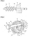
- the main body portion 10a is disposed in the motor placement portion 9a (see Figs. 2 and 3 ).
- the worm 11 is fixedly connected to the motor shaft 10b and disposed in the worm placement portion 9b.
- the worm 11 has a lead angle of 9°or more.
- the worm 11 has a cylindrical shaft portion 11a of which thickness is thin. A difference between a diameter D1 of a dedendum circle of the worm 11 and a diameter D2 of the motor shaft 10b is very small (see Fig. 3 ).
- the worm wheel 12 is made by integrally forming a driven gear (helical gear) 13 and a pinion 14 protruding laterally from the center portion of the driven gear 13 (see Figs. 2 and 4 ).
- the worm wheel 12 is disposed in the gear placement portion 9c and the center portion thereof is supported on the support shaft portion 7a of the case body 7 via a bearing 15.
- the driven gear 13 is engaged with the worm 11.
- the worm 11 has a lead angle of 9°or more. Therefore, irreversibility of the worm 11 is eliminated, so that the worm 11 is rotatable along with the rotation of the driven gear 13 even when the driven gear 13 is rotated in either direction.
- the pinion 14 is coaxial with the driven gear 13 and has an annular portion 16 supported in the state of being externally fitted on the bearing 15 and gear portions 17, 17, 17 provided on an outer peripheral side of the annular portion 16.
- the gear portions 17, 17, 17 are provided in the state of being spaced at regular intervals in the circumferential direction.
- Each gear portion 17 is configured by a plurality of gear teeth, for example, two gear teeth 17a, 17a.
- the number of the gear teeth 17a of the gear portion 17 is optional, and may be one or may be three or more.
- a diameter of an addendum circle of the pinion 14 is smaller than that of a dedendum circle of the driven gear 13. Therefore, a side surface 13a located on an outer peripheral side of the pinion 14 is formed on the side of the driven gear 13 where the pinion 14 is located. Portions between the gear portions 17, 17, 17 are respectively formed as toothless portions 14a, 14a, 14a where the gear tooth 17a is not provided. For example, three toothless portions 14a are formed in the state of being spaced in regular intervals in the circumferential direction.
- the worm wheel 12 is made by integrally forming the driven gear 13 and the pinion 14. Therefore, the number of parts can be reduced and a driving force transmitted from the drive motor 10 to the driven gear 13 can be effectively transmitted to the pinion 14, thereby reducing the size of the drive motor 10.
- the driven gear 13 and the pinion 14 are coaxially arranged, the driving force transmitted from the drive motor 10 to the driven gear 13 can be more effectively transmitted to the pinion 14, thereby further reducing the size of the drive motor 10.
- a thickness of the annular portion 16 of the pinion 14 is thin and a difference between a diameter D3 of a dedendum circle of the worm wheel 12 and a diameter D4 of the bearing 15 is very small (see Fig. 2 ).
- a cylinder 18 is coupled to a rear end portion of the case body 7.
- the cylinder 18 is coupled in a state of protruding rearward from the case body 7.
- the cylinder 18 is made by integrally forming a piston support portion 19 and a connection protruding portion 20 protruding rearward from the piston support portion 19.
- a diameter of the piston support portion 19 is greater than that of the connection protruding portion 20.
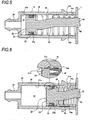
- An internal space 21 of the piston support portion 19 has a first space 21a which is an approximately rear half portion and a second space 21b which is an approximately front half portion (see Figs. 5 and 6 ).
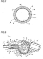
- Air inlet grooves 19a, 19a extending in the front-rear direction are formed in the state of being spaced in the circumferential direction in the second space 21b of the piston support portion 19 (see Figs. 5 to 7 ).
- the air inlet grooves 19a, 19a are arranged on 180° opposite sides, for example. Meanwhile, the number of the air inlet groove 19a is optional.
- these air inlet grooves are desirably formed at regular intervals in the circumferential direction.
- the portion of the second space 21b where the air inlet grooves 19a, 19a are formed has a diameter slightly larger than a diameter of the first space 21a.
- the portion of the second space 21b where the air inlet grooves 19a, 19a are not formed has the same diameter as the first space 21a.
- the piston 19 is configured such that stepped surfaces 21c, 21c are respectively formed at boundary portions between the first space 21a and the air inlet grooves 19a, 19a (see Fig. 6 ).
- the piston support portion 19 is formed with an air inlet hole (not shown) from which outside air is introduced into the air inlet grooves 19a, 19a.
- a center axis of the connection protruding portion 20 coincides with a center axis of the piston support portion 19.
- a front end portion of the pipe 3 is connected to the connection protruding portion 20.
- a piston 22 is movably supported in the piston support portion 19 of the cylinder 10.
- the piston 22 has a substantially cylindrical actuation portion 23 of which a thickness in the front-rear direction is thin and a connection portion 24 protruding obliquely forward and upward from the center portion of the actuation portion 23.
- An annular placement groove 23a opening outwardly is formed in the actuation portion 23.
- An outer diameter of the actuation portion 23 is slightly smaller than a diameter of the first space 21a of the piston support portion 19. Therefore, a gap 21d is formed between an outer peripheral surface of the actuation portion 23 and an inner peripheral surface of the piston support portion 19 in the first space 21a.
- a seal portion 25 is disposed in the placement groove 23a.
- the seal portion 25 is formed of, for example, an elastically deformable rubber or resin.
- An outer peripheral portion of the seal portion 25 protrudes outward from an outer peripheral surface of the actuation portion 23.
- the piston 22 reciprocates in the front-rear direction between the top dead center and the bottom dead center with respect to the cylinder 18.
- the whole of the actuation portion 23 is positioned in the first space 21a (see Fig. 5 ).
- the whole of the seal portion 25 is positioned in the second space 21b and a rear end portion of the actuation portion 23 is positioned in the first space 21a (see Fig. 6 ).
- the seal portion 25 of the piston 22 slides on an inner peripheral surface of the cylinder 18 in the first space 21a (see Fig. 5 ). Further, the seal portion 25 slides on an inner peripheral surface of the portion of the cylinder 18 other than the air inlet grooves 19a, 19a in the second space 21b.
- the seal portion 25 is spaced away from an inner peripheral surface of the piston support portion 19 of the cylinder 18 at the portion where the air inlet grooves 19a, 19a are formed (see Fig. 6 ). Therefore, in the state where the piston 22 is positioned at the bottom dead center, air (outside air) introduced into the second space 21b flows toward the first space 21a through the gap 21d along the steps 21c, 21c.
- a rack 26 extending in the front-rear direction is connected to the connection portion 24 of the piston 22.
- the rack 26 is formed integrally with the piston 22, for example.
- piston 22 and the rack 26 are integrally formed in this way, there is no need to separately form the piston 22 and the rack 26, respectively, thereby reducing the number of parts.
- the rack 26 is formed with a rack portion 27 at a position close to a front end thereof.
- the rack portion 27 is configured by, for example, three rack teeth 27a, 27a, 27a.
- the number of the rack tooth 27a of the rack portion 27 is optional and may be two or less or may be four or more.
- the rack 26 is inserted through the insertion hole 9d formed in the case body 7 and the rack portion 27 is engageable with the gear portion 17 of the pinion 14 in the worm wheel 12.
- An engagement reference line P of the rack portion 27 of the rack 26 substantially coincides with a center axis M of the piston 22.
- the movement direction of the piston 22 is substantially equal to the movement direction of the rack 26, thereby reducing the size of the drive motor 10 owing to the reduction in load of the drive motor 10.
- biasing spring 28 is supported on the inside of the piston support portion 19 of the cylinder 18.
- the biasing spring 28 is, for example, a compression coil spring.
- the piston 22 and the rack 26 are biased rearward by the biasing spring 28.
- the movement direction of the piston 22 is a feeding direction in which air is fed to the rear side.
- the piston 22 and the rack 26 are biased in the feeding direction by the biasing spring 28.
- the piston 22 In the initial state, the piston 22 is positioned at the top dead center, and the rack portion 27 of the rack 26 is not engaged with the gear portions 17, 17, 17 of the pinion 14 but is located on the toothless portion 14a.
- the piston 22 moved to the bottom dead center is moved in the feeding direction by the biasing force of the biasing spring 28 at higher speed than movement speed in the direction opposite to the feeding direction, and the air introduced into the first space 21a from the second space 21b is fed toward the nozzle 6 of the nozzle unit 2 through the connection protruding portion 20 from the piston support portion 19.
- the cylinder 18 has a configuration that the diameter of the connection protruding portion 20 is smaller than that of the piston support portion 19, the air fed through the connection protruding portion 20 from the piston support portion 19 is compressed into high-pressure air and fed toward the nozzle 6 through the pipe 3. Then, the high-pressure air is injected from the nozzle 6 and blown to the lens portion 101 of the imaging unit of the in-vehicle camera 100.
- the diameter of at least a portion of the second space 21b of the cylinder 18 is larger than that of the first space 21a. Further, when the piston 22 is moved to the bottom dead center, the whole of the seal portion 25 is located in the second space 21b and the air introduced into the second space 21b flows toward the first space 21a from the second space 21b.
- the difference between the diameter of at least a portion of the second space 21b and the diameter of the first space 21a is realized by the air inlet grooves 19a, 19a, a structure for realizing the difference between the diameter of the second space 21b and the diameter of the first space 21a can be simplified and the actuation portion 23 of the piston 22 can be moved relative to the cylinder 18 also in the second space 21b, so that the stable moving state of the piston 22 can be ensured.
- the air inlet grooves 19a, 19a are formed in the state of being spaced at a regular interval in the circumferential direction, the flow of air from the second space 21b to the first space 21a is equalized in the circumferential direction of the cylinder 18. Therefore, vibration does not occur during the movement of the piston 22, and hence, the stable movement state of the piston 22 can be ensured.
- the above-described reciprocating movement of the piston 22 between the top dead center and the bottom dead center is performed by using an engagement between the gear portion 17 of the pinion 14 and the rack portion 27 of the rack 26 and a release therebetween as one cycle, and the movement in the feeding direction of the piston 22 is performed by the presence of the toothless portion 14a of the pinion 14.
- the foreign material removal device 1 is configured in such that the gear portions 17, 17, 17 are provided at three positions spaced in the circumferential direction of the pinion 14 and three toothless portions 14a, 14a, 14a are formed, the reciprocating movement of the piston 22 between the top dead center and the bottom dead center is performed three times (three cycles) during one rotation of the pinion 14.
- the number of times of injection of the high-pressure air from the nozzle 6 during one rotation of the pinion 14 can be increased, thereby improving the injection efficiency in the foreign material removal device 1.
- the diameter of the addendum circle of the pinion 14 is smaller than that of the dedendum circle of the driven gear 13, and the piston 22 is moved in a stable state in the front-rear direction by being slid on the side surface 13a of the driven gear 13 when being reciprocated.
- the worm 11 has a lead angle of 9° or more. Therefore, when the driving of the drive motor 10 is stopped, the piston 22 is moved in the feeding direction by the biasing force of the biasing spring 28 and returns to the top dead center, and the engagement between the gear portion 17 of the pinion 14 and the rack portion 27 of the rack 26 is released. Therefore, the load of the drive motor 10 at the start of the operation of the foreign material removal device 1 can be reduced, and wear between the gear portion 17 of the pinion 14 and the rack portion 27 of the rack 26 due to vibration or the like occurring during the driving of the vehicle can be prevented.
- the foreign material removal device 1 is provided with the cylinder 18 into which air is caused to flow, the piston 22 which is movably supported in the cylinder 18 and feeds the air introduced into the cylinder 18 as high-pressure air, and the nozzle 6 which injects the high-pressure air fed by the piston 22 toward the imaging unit of the in-vehicle camera 100.
- the biasing force of the biasing spring 28 is increased as the piston 22 is moved in the direction opposite to the feeding direction by the moving mechanism 8.
- the application of the moving force of the moving mechanism 8 to the piston 22 is released and the piston 22 is moved in the feeding direction by the biasing force of the biasing spring 28, thereby feeding the high-pressure air.
- the moving mechanism 8 needs to apply a moving force in only one direction to the piston 22, the configuration of the moving mechanism 8 is simplified. Since the piston 22 is moved at a high speed in the feeding direction by the biasing spring 28 in order to generate high pressure air, it is possible to achieve the simplification of the mechanism of the foreign material removal device 1.
- a driving force of the drive motor 10 is transmitted to the piston 22 through the worm 11 and the worm wheel 12
- a reduction mechanism in which a large reduction ratio is obtained by a simple mechanism having a small number of parts is configured by using the worm 11 and the worm wheel 12.
- high conversion efficiency of the moving force of the piston 22 to the driving force of the drive motor 10 can be ensured by a simple mechanism.
- the piston 22 serves as a valve for flow and stop of air into the first space 21a of the cylinder 10 has been described.
- the foreign material removal device I may be provided with a valve (check valve).
- a valve check valve
- FIG. 11 and 11 an example where the check valve is provided will be described (see Figs. 11 and 11 ).
- An air inlet hole communicating with the first space 21a may be formed in the piston support portion 19 of the cylinder 18 and air (outside air) may flow into the first space 21a from the air inlet hole.
- each of the following examples where a check valve is provided is different only in the configuration of a rear end portion of the piston 22, as compared with the above configuration in which a check valve is not provided. Accordingly, a detailed description will be given only to the portions different from those of the above configuration, and the other portions are denoted by the same reference numeral as the above configuration and a description thereof is omitted.
- a check valve 29 is mounted to an inner side of the connection protruding portion 20 of the cylinder 18.
- the check valve 29 is configured by a plurality of elastic members 29a, 29a, ... formed of, for example, a rubber material or the like, and leading ends thereof are displaced to be curved rearward and are abutted against each other.
- the air in the first space 21a is compressed, and hence, an internal pressure of the first space 21a is increased, thereby generating high-pressure air.
- the leading ends of the elastic members 29a, 29a, ... are elastically deformed so as to be spaced apart from each other by the pressure of the high-pressure air.
- an opening is formed at the center portion of the check valve 29 and the high-pressure air flows toward the nozzle 6 through the opening of the check valve 29 from the first space 21a.
- the first space 21a becomes a negative pressure state and air (outside air) flows into the first space 21a from the air inlet hole.
- a structure that has no connection protruding portion 20 is provided as a cylinder 18A, and a cap 30 is mounted to a rear end portion of the cylinder 18A in an externally fitted state.
- the cap 30 is made by integrally forming a mounted portion 31 mounted to the rear end portion of the cylinder 18A and a connection protruding portion 32 protruding rearward from the mounted portion 31.
- a diameter of the mounted portion 31 is larger than that of the connection protruding portion 32.
- a center axis of the connection protruding portion 32 coincides with a center axis of the piston support portion 19 of the cylinder 18A.
- a front end portion of the pipe 3 is connected to the connection protruding portion 32.
- a support hole 18a penetrating in the front-rear direction is formed at the rear end portion of the cylinder 18A.
- a check valve 33 is supported in the support hole 18a so as to be movable in the front-rear direction.
- the check valve 33 is formed of an elastically deformable material such as a rubber.
- the check valve 33 is composed of a supported shaft portion 33a extending in the front-rear direction, an opening and closing portion 33b protruding outward from a rear end portion of the supported shaft portion 33a, and stopper portions 33c, 33c, ⁇ protruding outward from a front end portion of the supported shaft portion 33a.
- a length of the supported shaft portion 33a is longer than that of the support hole 18a and an outer diameter the supported shaft portion 33a is smaller than a diameter of the support hole 18a.
- the stopper portions 33c, 33c, ⁇ are projected radially from the supported shaft portion 33a and are spaced apart from each other in the circumferential direction.
- the first space 21a becomes a negative pressure state and air (outside air) is introduced into the first space 21a from the air inlet hole.
- a moving mechanism 8A according to the modification illustrated below is different from the moving mechanism 8 described above only in the structures of the worm wheel and the rack. Accordingly, a detailed description will be given only to the portions different from the moving mechanism 8, and the other portions are denoted by the same reference numeral as the moving mechanism 8 and a description thereof is omitted.
- the moving mechanism 8A includes the drive motor 10, the worm 11 and a worm wheel 12A.
- the worm wheel 12A is made by integrally forming the driven gear 13 and a pinion 14A (see Fig. 13 ).
- the pinion 14A has the annular portion 16 and gear portions 17A, 17A, 17A.
- the gear portions 17A, 17A, 17A are provided in the state of being spaced at regular intervals in the circumferential direction.
- the gear portion 17A is configured by the first gear teeth 17a, 17a and the second gear tooth 17b, for example.
- at least one first gear tooth 17a and at least one second gear tooth 17b may be respectively provided and the numbers of the first gear tooth 17a and the second gear tooth 17b are optional, respectively.
- the second gear tooth 17b has a width equal to or less than the half of a width of the first gear tooth 17a and is positioned on the driven gear 13 side, for example.
- the second gear tooth 17b is positioned on the rotation direction side of the worm wheel 12A with respect to the first gear teeth 17a, 17a.
- a rack 26A extending in the front-rear direction is connected to the connection portion 24 of the piston 22.
- the rack 26A is formed integrally with the piston 22, for example.
- a rack portion 27A is formed on a front end side of the rack 26A (see Fig. 14 ).
- the rack portion 27A is configured by, for example, a first rack tooth 27a and second rack teeth 27b, 27b, 27b. Meanwhile, in the rack portion 27A, at least one first rack tooth 27a and at least one second rack tooth 27b may be respectively provided and the numbers of the first gear tooth 27a and the second gear tooth 27b are optional, respectively.
- the first rack tooth 27a is located at a front end portion of the rack 26A.
- the second rack tooth 27b has a width equal to or less than the half of a width of the first rack tooth 27a and is positioned on the side away from the driven gear 13 in the state where the rack portion 27A is engaged with the gear portion 17A of the pinion 14A.
- the rack portion 27A is formed with a cutout portion 27c which is continuous with the second rack tooth 27b located at the rearmost side.
- the cutout portion 27c is opened to the driven gear 13 side and to the lower side and a rear end portion thereof is formed in an arcuate shape.
- the piston 22 is positioned at the top dead center and the rack 26A is positioned in a state where the first rack tooth 27a of the rack portion 27A is engageable with or engaged with the second gear tooth 17b of the gear portion 17A of the pinion 14A.
- the pinion 14A When the driving of the drive motor 10 is started in the initial state, the pinion 14A is rotated in the state where the gear portion 17A of the pinion 14A is engaged with the rack portion 27A of the rack 26A. Thus, the rack 26A is moved, together with the piston 22, in the direction opposite to the feeding direction against the biasing force of the biasing spring 28 (see Fig. 16 ).
- the second gear tooth 17b of the pinion 14A and the second rack teeth 27b, 27b, 27b of the rack 26A are offset from each other when the rack 26A is moved in the feeding direction.
- the movement amount of the piston 22 can be increased without increasing the diameter of the pinion 14A, it is possible to reduce the size of the foreign material removal device 1 and it is possible to ensure the required movement amount of the piston 22 without increasing the driving force of the drive motor 10.
- the width of the second gear tooth 17b of the pinion 14A is equal to or less than the half of the width of the first gear tooth 17a and the width of the second rack tooth 27b of the rack 26A is equal to or less than the half of the width of the first rack tooth 27a, it is possible to increase the movement amount of the piston 22 without increasing the diameter of the pinion 14A.
Landscapes
- Engineering & Computer Science (AREA)
- Mechanical Engineering (AREA)
- General Engineering & Computer Science (AREA)
- Transmission Devices (AREA)
- Cleaning In General (AREA)
- Compressors, Vaccum Pumps And Other Relevant Systems (AREA)
- Multimedia (AREA)
- Nozzles (AREA)
Claims (11)
- Eine fahrzeuginterne Vorrichtungsbaugruppe, die eine fahrzeuginterne Vorrichtung wie beispielsweise eine Kamera, eine Lampe oder einen Kollisionsverhinderungssensor und eine Fremdmaterialentfernungsvorrichtung (1) zum Entfernen von Fremdmaterial von der fahrzeuginternen Vorrichtung (100) aufweist,
wobei die Fremdmaterialentfernungsvorrichtung (1) umfasst:einen Zylinder (18), wobei Luft veranlasst wird, in diesen zu strömen;einen Kolben (22), der beweglich in dem Zylinder (18) gelagert ist und die in den Zylinder (18) eingeführte Luft in einer Einführungsrichtung als Hochdruckluft einführt;eine Düse (6), die die von dem Kolben (22) eingeführte Hochdruckluft einspeist,wobei ein Bewegungsmechanismus (8A) eine Schnecke (11), die von einer Antriebskraft eines Antriebsmotors (10) gedreht wird, und ein Schneckenrad (12) beinhaltet, das mit der Schnecke (11) in Eingriff steht und von der Drehung der Schnecke (11) gedreht wird, unddie Antriebskraft des Antriebsmotors (10) an den Kolben (22) über die Schnecke (11) und das Schneckenrad (12) übertragen wird,eine Zahnstange (26), die mit dem Kolben (22) verbunden ist, vorgesehen ist,ein Ritzel (14), das durch die Zahnstange (26) in Eingriff steht, in dem Schneckenrad (12) vorgesehen ist,ein Zahnradzahn (17a) in einem Abschnitt einer äußeren Peripherie des Ritzels (14) vorgesehen ist,ein Abschnitt der äußeren Peripherie des Ritzels (14), an dem der Zahnradzahn (17a) nicht vorgesehen ist, als ein zahnloser Abschnitt (14a) ausgebildet ist, undder Abschnitt der äußeren Peripherie des Ritzels (14), an dem der Zahnradzahn (17a) vorgesehen ist, als ein Zahnradabschnitt vorgesehen ist, undeine Vielzahl der Zahnradabschnitte (17a) so ausgebildet ist, dass die Zahnradabschnitte (17a) miteinander in einer Umfangsrichtung beabstandet sind. - Die fahrzeuginterne Vorrichtungsbaugruppe gemäß Anspruch 1, wobei die Fremdmaterialentfernungsvorrichtung (1) umfasst:eine Vorspannungsfeder (28) zum Vorspannen des Kolbens (22) in der Einführungsrichtung,der Bewegungsmechanismus (8A) zum Bewegen des Kolbens (22) an eine vorgegebene Position in einer Richtung entgegengesetzt zu der Einführungsrichtung durch Aufbringen einer Bewegungskraft auf den Kolben (22) vorgesehen ist,die Vorspannungskraft der Vorspannungsfeder (28) erhöht wird, wenn der Kolben (22) in der Richtung entgegengesetzt zu der Einführungsrichtung durch den Bewegungsmechanismus (8A) bewegt wird, undwenn der Kolben (22) an die vorgegebene Position durch den Bewegungsmechanismus (8A) bewegt wird, die Aufbringung der Bewegungskraft auf den Kolben (22) durch den Bewegungsmechanismus (8A) gelöst wird, der Kolben (22) in der Einführungsrichtung durch die Vorspannungskraft der Vorspannungsfeder (28) bewegt wird, undHochdruckluft eingeführt wird.
- Die fahrzeuginterne Vorrichtungsbaugruppe gemäß Anspruch 1, wobei der Kolben (22) und die Zahnstange (26) integral ausgebildet sind.
- Die fahrzeuginterne Vorrichtungsbaugruppe gemäß irgendeinem der Ansprüche 1 bis 3, wobei eine Mittelachse des Kolbens (22) und eine Eingriffsbezugslinie der Zahnstange (26) im Wesentlichen übereinstimmen.
- Die fahrzeuginterne Vorrichtungsbaugruppe gemäß irgendeinem der Ansprüche 1 bis 4, wobei die Schnecke (11) einen Steigungswinkel von 9° oder mehr aufweist.
- Die fahrzeuginterne Vorrichtungsbaugruppe gemäß irgendeinem der Ansprüche 1 bis 5, wobei
der Zahnradabschnitt (17a) mit einer Vielzahl von Zahnradzähnen (17) versehen ist,
die Zahnstange (26) mit einer Vielzahl von Zahnstangenzähnen (27a) versehen ist,
die Vielzahl von Zahnradzähnen (17) von einem ersten Zahnradzahn (17a) und einem zweiten Zahnradzahn (17b) zusammengesetzt ist,
die Vielzahl von Zahnstangenzähnen (27a) von einem ersten Zahnstangenzahn (27a) und einem zweiten Zahnstangenzahn (27b) zusammengesetzt ist,
der erste Zahnradzahn (17a) mit dem ersten Zahnstangenzahn (27a) und dem zweiten Zahnstangenzahn (27b) in Eingriff bringbar ist,
der zweite Zahnradzahn (17b) mit dem ersten Zahnstangenzahn (27a) in Eingriff bringbar ist, aber nicht mit dem zweiten Zahnstangenzahn (27b) in Eingriff bringbar ist, und
der zweite Zahnradzahn (17b) und der zweite Zahnstangenzahn (27b) voneinander versetzt sind, wenn die Zahnstange (26) bewegt wird und das Schneckenrad (12) durch die Bewegung des Kolbens (22) in der Einführungsrichtung gedreht wird. - Die fahrzeuginterne Vorrichtungsbaugruppe gemäß Anspruch 6, wobei
eine Breite des zweiten Zahnradzahns (17b) gleich oder weniger als die Hälfte einer Breite des ersten Zahnradzahns (17a) ist, und
eine Breite des zweiten Zahnstangenzahns (27b) gleich oder weniger als die Hälfte einer Breite des ersten Zahnstangenzahns (27a) ist. - Die fahrzeuginterne Vorrichtungsbaugruppe gemäß irgendeinem der Ansprüche 1 bis 7, wobei
ein interner Raum des Zylinders (18) einen ersten Raum (21a) und einen zweiten Raum (21b) aufweist, die miteinander in der Bewegungsrichtung des Kolbens (22) kontinuierlich sind,
der erste Raum (21a) an der Einführungsrichtungsseite als der zweite Raum (21b) gelegen ist,
ein Durchmesser von zumindest einem Abschnitt des zweiten Raums (21b) größer als ein Durchmesser des ersten Raums (21a) ist,
der Kolben (22) mit einem Dichtabschnitt (25) versehen ist, der in engen Kontakt mit einer inneren Peripherieoberfläche des Zylinders zumindest in dem ersten Raum (21a) während Bewegung gebracht ist, und
wenn der Kolben (22) zu dem unteren Totpunkt bewegt wird, der ganze Dichtabschnitt in dem zweiten Raum (21b) positioniert ist und die in den zweiten Raum (21b) eingeführte Luft von dem zweiten Raum (21b) zu dem ersten Raum (21a) strömt. - Die fahrzeuginterne Vorrichtungsbaugruppe gemäß Anspruch 8, wobei
eine Lufteinlassnut (19a), die sich in der Bewegungsrichtung des Kolbens (22) erstreckt, an einer äußeren Peripherieseite des zweiten Raums (21b) ausgebildet ist, und
die Lufteinlassnut (19a) als der Abschnitt ausgebildet ist. - Die fahrzeuginterne Vorrichtungsbaugruppe gemäß Anspruch 9, wobei
eine Vielzahl der Lufteinlassnuten (19a) so ausgebildet ist, dass die Lufteinlassnuten (19a) an regulären Intervallen in der Umfangsrichtung beabstandet sind. - Die fahrzeuginterne Vorrichtungsbaugruppe gemäß irgendeinem der Ansprüche 1 bis 10, wobei
der fahrzeuginterne Sensor eine fahrzeuginterne Kamera ist und Hochdruckluft von der Düse (6) zu einer Bildeinheit der fahrzeuginternen Kamera (100) eingespeist wird, und die Düse (6) integral mit der fahrzeuginternen Kamera (100) ausgebildet ist.
Applications Claiming Priority (5)
| Application Number | Priority Date | Filing Date | Title |
|---|---|---|---|
| JP2014082986 | 2014-04-14 | ||
| JP2014082988 | 2014-04-14 | ||
| JP2014082987 | 2014-04-14 | ||
| JP2015024478 | 2015-02-10 | ||
| PCT/JP2015/060877 WO2015159763A1 (ja) | 2014-04-14 | 2015-04-07 | 異物除去装置 |
Publications (3)
| Publication Number | Publication Date |
|---|---|
| EP3132984A1 EP3132984A1 (de) | 2017-02-22 |
| EP3132984A4 EP3132984A4 (de) | 2018-04-04 |
| EP3132984B1 true EP3132984B1 (de) | 2019-11-20 |
Family
ID=54323974
Family Applications (1)
| Application Number | Title | Priority Date | Filing Date |
|---|---|---|---|
| EP15779331.6A Active EP3132984B1 (de) | 2014-04-14 | 2015-04-07 | Fahrzeugeigene vorrichtung mit fremdmaterialbeseitigung |
Country Status (5)
| Country | Link |
|---|---|
| US (2) | US10436186B2 (de) |
| EP (1) | EP3132984B1 (de) |
| JP (1) | JP6712436B2 (de) |
| CN (1) | CN106163888B (de) |
| WO (1) | WO2015159763A1 (de) |
Families Citing this family (23)
| Publication number | Priority date | Publication date | Assignee | Title |
|---|---|---|---|---|
| JP6654145B2 (ja) * | 2014-12-22 | 2020-02-26 | 株式会社小糸製作所 | 異物除去装置、除去駆動装置 |
| JP6641369B2 (ja) * | 2015-06-30 | 2020-02-05 | 株式会社小糸製作所 | 異物除去装置および当該異物除去装置を備える車両 |
| EP3581445B1 (de) | 2015-06-30 | 2021-11-03 | Koito Manufacturing Co., Ltd. | Fremdstoffentfernungsvorrichtung und fahrzeug mit dieser fremdstoffentfernungsvorrichtung |
| EP3318454B1 (de) * | 2015-06-30 | 2021-06-02 | Koito Manufacturing Co., Ltd. | Fremdstoffbeseitigungsvorrichtung und damit ausgestattetes fahrzeug |
| EP3318453B1 (de) | 2015-06-30 | 2020-11-18 | Koito Manufacturing Co., Ltd. | Fremdstoffbeseitigungsvorrichtung und damit ausgestattetes fahrzeug |
| JP6772618B2 (ja) * | 2015-11-19 | 2020-10-21 | 株式会社デンソー | 電動エアポンプ |
| JP6654430B2 (ja) | 2015-12-28 | 2020-02-26 | 株式会社デンソーテン | 噴射装置および噴射システム |
| JP6651897B2 (ja) * | 2016-02-25 | 2020-02-19 | 株式会社富士通ゼネラル | 水滴除去機構とこれを備えた車載カメラ |
| DE112017001606T5 (de) | 2016-03-31 | 2018-12-13 | Denso Corporation | Reinigungsvorrichtung für einen bordseitigen optischen Sensor |
| CN105847760B (zh) * | 2016-05-20 | 2019-03-05 | 温州电力设计有限公司 | 一种图像监控装置 |
| JP6828350B2 (ja) * | 2016-09-30 | 2021-02-10 | 株式会社デンソー | 電動エアポンプ及び車載光学センサ洗浄装置 |
| JP6811083B2 (ja) * | 2016-12-12 | 2021-01-13 | 株式会社小糸製作所 | クリーナおよびクリーナを備える車両 |
| WO2018123517A1 (ja) | 2016-12-28 | 2018-07-05 | 株式会社小糸製作所 | 車両用クリーナシステムおよび車両用クリーナシステムを備える車両、車両用クリーナおよび車両用クリーナを備える車両 |
| JP6764385B2 (ja) | 2017-01-20 | 2020-09-30 | 株式会社ニフコ | 車両用カメラに対する流体の吹き付け装置 |
| JP6781078B2 (ja) | 2017-03-02 | 2020-11-04 | 株式会社ホンダアクセス | 噴射用ノズル部材 |
| US11225955B2 (en) | 2017-06-09 | 2022-01-18 | Denso Corporation | Electric pump device |
| JP6977514B2 (ja) | 2017-06-09 | 2021-12-08 | 株式会社デンソー | 車載センサ洗浄装置 |
| CN111051157B (zh) * | 2017-08-28 | 2023-07-07 | 株式会社小糸制作所 | 异物去除装置 |
| JP7161893B2 (ja) | 2018-08-31 | 2022-10-27 | 株式会社デンソーテン | 圧縮装置 |
| KR102000269B1 (ko) * | 2019-01-31 | 2019-07-15 | 샘찬에너지(주) | 수소가스 압축 장치 |
| CN114291037B (zh) * | 2020-10-07 | 2025-03-07 | 株式会社小糸制作所 | 车辆清洗装置、其制造方法及其组装方法 |
| JP2023170161A (ja) * | 2022-05-18 | 2023-12-01 | 株式会社デンソーテン | 気体噴射装置 |
| JPWO2024142274A1 (de) * | 2022-12-27 | 2024-07-04 |
Family Cites Families (18)
| Publication number | Priority date | Publication date | Assignee | Title |
|---|---|---|---|---|
| US2260113A (en) * | 1940-02-19 | 1941-10-21 | Frost Orley Ray | Vacuum pump control |
| US2309339A (en) * | 1941-05-21 | 1943-01-26 | Akron Lamp & Mfg Company | Pump |
| JPH03102652A (ja) * | 1989-09-18 | 1991-04-30 | Canon Inc | 光学的情報記録再生装置 |
| JPH05184546A (ja) | 1992-01-08 | 1993-07-27 | Canon Inc | 非接触眼圧計 |
| JP2581418B2 (ja) * | 1993-10-28 | 1997-02-12 | 日本電気株式会社 | 光ディスク装置 |
| JP2001171491A (ja) * | 1999-12-16 | 2001-06-26 | Matsushita Electric Ind Co Ltd | 車載カメラ装置及び車載カメラの洗浄方法 |
| JP3934302B2 (ja) * | 2000-03-27 | 2007-06-20 | ミナミ株式会社 | 実装プリント配線基板の部品に塗布した腐食防止固定材の真空脱泡装置 |
| JP2004202145A (ja) * | 2002-12-26 | 2004-07-22 | Yamanouchi Trading:Kk | エアガン用ピストンシリンダ装置及びエアガン |
| JP4133749B2 (ja) * | 2003-11-07 | 2008-08-13 | 本田技研工業株式会社 | 車両のシートベルト装置 |
| JP2007315030A (ja) * | 2006-05-25 | 2007-12-06 | Kidoh Tech Co Ltd | 石綿管の撤去方法 |
| JP2008213007A (ja) * | 2007-03-07 | 2008-09-18 | Eiji Suga | 自動組立装置における制御装置 |
| JP3137755U (ja) * | 2007-09-26 | 2007-12-06 | 高浩 浦 | 弾接触面を有するノズル、弾の発射装置及び玩具空気銃 |
| JP5654995B2 (ja) * | 2008-10-14 | 2015-01-14 | フェルトン ホールディング エスアー | 生体への衝撃波導入装置及びその利用 |
| US20100167236A1 (en) * | 2008-12-29 | 2010-07-01 | Koninklijke Philips Electronics N.V. | Non-pressurized system fore creating liquid droplets in a dental cleaning appliance |
| BR112013007026A2 (pt) | 2010-09-29 | 2020-10-13 | Koninklijke Philips Electronics N.V | aparelho para uso em um sistema de gotículas de líquido para limpeza dos dentes, para produção de impulsos sucessivos de ar e impulsos sucessivos de líquido com um conjunto de motor |
| US9796359B2 (en) * | 2012-02-23 | 2017-10-24 | The Raymond Corporation | Method and apparatus for removing and preventing lens surface contamination on a vehicle lens |
| US20140023537A1 (en) * | 2012-07-19 | 2014-01-23 | Wei-Chi Wang | Air Pump Cylinder |
| JP2014166806A (ja) * | 2013-02-28 | 2014-09-11 | Mitsubishi Heavy Ind Ltd | 管内走行装置及び管内検査装置 |
-
2015
- 2015-04-07 CN CN201580019594.3A patent/CN106163888B/zh active Active
- 2015-04-07 EP EP15779331.6A patent/EP3132984B1/de active Active
- 2015-04-07 WO PCT/JP2015/060877 patent/WO2015159763A1/ja not_active Ceased
- 2015-04-07 US US15/303,972 patent/US10436186B2/en active Active
- 2015-04-07 JP JP2016513730A patent/JP6712436B2/ja active Active
-
2019
- 2019-08-13 US US16/539,018 patent/US11225224B2/en active Active
Non-Patent Citations (1)
| Title |
|---|
| None * |
Also Published As
| Publication number | Publication date |
|---|---|
| US10436186B2 (en) | 2019-10-08 |
| CN106163888B (zh) | 2019-06-28 |
| US20170028968A1 (en) | 2017-02-02 |
| CN106163888A (zh) | 2016-11-23 |
| WO2015159763A1 (ja) | 2015-10-22 |
| JPWO2015159763A1 (ja) | 2017-04-13 |
| JP6712436B2 (ja) | 2020-06-24 |
| US20190359180A1 (en) | 2019-11-28 |
| EP3132984A4 (de) | 2018-04-04 |
| US11225224B2 (en) | 2022-01-18 |
| EP3132984A1 (de) | 2017-02-22 |
Similar Documents
| Publication | Publication Date | Title |
|---|---|---|
| US11225224B2 (en) | Foreign material removal device | |
| JP7663646B2 (ja) | 車両用クリーナシステムおよび車両用クリーナシステムを備える車両 | |
| JP6417757B2 (ja) | 車載光学センサ洗浄装置 | |
| US20210362689A1 (en) | Foreign material removing device and vehicle provided with this foreign material removing device | |
| CN110371082B (zh) | 车载光学传感器清洗装置 | |
| JP7555707B2 (ja) | ライセンスプレートランプユニットおよびライセンスプレートランプユニットを備える車両 | |
| CN108238009B (zh) | 清洗器和包括清洗器的车辆 | |
| JP7182551B2 (ja) | 異物除去装置 | |
| US20190145411A1 (en) | Gas ejection apparatus | |
| JP2026071140A (ja) | クリーナ | |
| WO2026083798A1 (ja) | クリーナ | |
| JP2022157200A (ja) | 噴射装置および噴射方法 |
Legal Events
| Date | Code | Title | Description |
|---|---|---|---|
| STAA | Information on the status of an ep patent application or granted ep patent |
Free format text: STATUS: THE INTERNATIONAL PUBLICATION HAS BEEN MADE |
|
| PUAI | Public reference made under article 153(3) epc to a published international application that has entered the european phase |
Free format text: ORIGINAL CODE: 0009012 |
|
| STAA | Information on the status of an ep patent application or granted ep patent |
Free format text: STATUS: REQUEST FOR EXAMINATION WAS MADE |
|
| 17P | Request for examination filed |
Effective date: 20161014 |
|
| AK | Designated contracting states |
Kind code of ref document: A1 Designated state(s): AL AT BE BG CH CY CZ DE DK EE ES FI FR GB GR HR HU IE IS IT LI LT LU LV MC MK MT NL NO PL PT RO RS SE SI SK SM TR |
|
| AX | Request for extension of the european patent |
Extension state: BA ME |
|
| DAV | Request for validation of the european patent (deleted) | ||
| DAX | Request for extension of the european patent (deleted) | ||
| A4 | Supplementary search report drawn up and despatched |
Effective date: 20180307 |
|
| RIC1 | Information provided on ipc code assigned before grant |
Ipc: B60S 1/60 20060101AFI20180301BHEP Ipc: F04B 9/02 20060101ALI20180301BHEP Ipc: H04N 7/18 20060101ALI20180301BHEP Ipc: H04N 5/225 20060101ALI20180301BHEP Ipc: B60R 1/00 20060101ALI20180301BHEP |
|
| STAA | Information on the status of an ep patent application or granted ep patent |
Free format text: STATUS: EXAMINATION IS IN PROGRESS |
|
| 17Q | First examination report despatched |
Effective date: 20181011 |
|
| REG | Reference to a national code |
Ref country code: DE Ref legal event code: R079 Ref document number: 602015042130 Country of ref document: DE Free format text: PREVIOUS MAIN CLASS: B60S0001600000 Ipc: B60S0001540000 |
|
| GRAP | Despatch of communication of intention to grant a patent |
Free format text: ORIGINAL CODE: EPIDOSNIGR1 |
|
| STAA | Information on the status of an ep patent application or granted ep patent |
Free format text: STATUS: GRANT OF PATENT IS INTENDED |
|
| RIC1 | Information provided on ipc code assigned before grant |
Ipc: B60S 1/60 20060101ALI20190508BHEP Ipc: B60R 1/00 20060101ALI20190508BHEP Ipc: F04B 9/02 20060101ALI20190508BHEP Ipc: H04N 7/18 20060101ALI20190508BHEP Ipc: B60S 1/54 20060101AFI20190508BHEP Ipc: H04N 5/225 20060101ALI20190508BHEP |
|
| INTG | Intention to grant announced |
Effective date: 20190606 |
|
| GRAS | Grant fee paid |
Free format text: ORIGINAL CODE: EPIDOSNIGR3 |
|
| GRAA | (expected) grant |
Free format text: ORIGINAL CODE: 0009210 |
|
| STAA | Information on the status of an ep patent application or granted ep patent |
Free format text: STATUS: THE PATENT HAS BEEN GRANTED |
|
| AK | Designated contracting states |
Kind code of ref document: B1 Designated state(s): AL AT BE BG CH CY CZ DE DK EE ES FI FR GB GR HR HU IE IS IT LI LT LU LV MC MK MT NL NO PL PT RO RS SE SI SK SM TR |
|
| REG | Reference to a national code |
Ref country code: GB Ref legal event code: FG4D |
|
| REG | Reference to a national code |
Ref country code: CH Ref legal event code: EP |
|
| REG | Reference to a national code |
Ref country code: IE Ref legal event code: FG4D |
|
| REG | Reference to a national code |
Ref country code: DE Ref legal event code: R096 Ref document number: 602015042130 Country of ref document: DE |
|
| REG | Reference to a national code |
Ref country code: AT Ref legal event code: REF Ref document number: 1203840 Country of ref document: AT Kind code of ref document: T Effective date: 20191215 |
|
| REG | Reference to a national code |
Ref country code: NL Ref legal event code: MP Effective date: 20191120 |
|
| REG | Reference to a national code |
Ref country code: LT Ref legal event code: MG4D |
|
| PG25 | Lapsed in a contracting state [announced via postgrant information from national office to epo] |
Ref country code: NL Free format text: LAPSE BECAUSE OF FAILURE TO SUBMIT A TRANSLATION OF THE DESCRIPTION OR TO PAY THE FEE WITHIN THE PRESCRIBED TIME-LIMIT Effective date: 20191120 Ref country code: GR Free format text: LAPSE BECAUSE OF FAILURE TO SUBMIT A TRANSLATION OF THE DESCRIPTION OR TO PAY THE FEE WITHIN THE PRESCRIBED TIME-LIMIT Effective date: 20200221 Ref country code: NO Free format text: LAPSE BECAUSE OF FAILURE TO SUBMIT A TRANSLATION OF THE DESCRIPTION OR TO PAY THE FEE WITHIN THE PRESCRIBED TIME-LIMIT Effective date: 20200220 Ref country code: BG Free format text: LAPSE BECAUSE OF FAILURE TO SUBMIT A TRANSLATION OF THE DESCRIPTION OR TO PAY THE FEE WITHIN THE PRESCRIBED TIME-LIMIT Effective date: 20200220 Ref country code: FI Free format text: LAPSE BECAUSE OF FAILURE TO SUBMIT A TRANSLATION OF THE DESCRIPTION OR TO PAY THE FEE WITHIN THE PRESCRIBED TIME-LIMIT Effective date: 20191120 Ref country code: LV Free format text: LAPSE BECAUSE OF FAILURE TO SUBMIT A TRANSLATION OF THE DESCRIPTION OR TO PAY THE FEE WITHIN THE PRESCRIBED TIME-LIMIT Effective date: 20191120 Ref country code: SE Free format text: LAPSE BECAUSE OF FAILURE TO SUBMIT A TRANSLATION OF THE DESCRIPTION OR TO PAY THE FEE WITHIN THE PRESCRIBED TIME-LIMIT Effective date: 20191120 Ref country code: LT Free format text: LAPSE BECAUSE OF FAILURE TO SUBMIT A TRANSLATION OF THE DESCRIPTION OR TO PAY THE FEE WITHIN THE PRESCRIBED TIME-LIMIT Effective date: 20191120 |
|
| PG25 | Lapsed in a contracting state [announced via postgrant information from national office to epo] |
Ref country code: IS Free format text: LAPSE BECAUSE OF FAILURE TO SUBMIT A TRANSLATION OF THE DESCRIPTION OR TO PAY THE FEE WITHIN THE PRESCRIBED TIME-LIMIT Effective date: 20200320 Ref country code: RS Free format text: LAPSE BECAUSE OF FAILURE TO SUBMIT A TRANSLATION OF THE DESCRIPTION OR TO PAY THE FEE WITHIN THE PRESCRIBED TIME-LIMIT Effective date: 20191120 Ref country code: HR Free format text: LAPSE BECAUSE OF FAILURE TO SUBMIT A TRANSLATION OF THE DESCRIPTION OR TO PAY THE FEE WITHIN THE PRESCRIBED TIME-LIMIT Effective date: 20191120 |
|
| PG25 | Lapsed in a contracting state [announced via postgrant information from national office to epo] |
Ref country code: AL Free format text: LAPSE BECAUSE OF FAILURE TO SUBMIT A TRANSLATION OF THE DESCRIPTION OR TO PAY THE FEE WITHIN THE PRESCRIBED TIME-LIMIT Effective date: 20191120 |
|
| PG25 | Lapsed in a contracting state [announced via postgrant information from national office to epo] |
Ref country code: DK Free format text: LAPSE BECAUSE OF FAILURE TO SUBMIT A TRANSLATION OF THE DESCRIPTION OR TO PAY THE FEE WITHIN THE PRESCRIBED TIME-LIMIT Effective date: 20191120 Ref country code: ES Free format text: LAPSE BECAUSE OF FAILURE TO SUBMIT A TRANSLATION OF THE DESCRIPTION OR TO PAY THE FEE WITHIN THE PRESCRIBED TIME-LIMIT Effective date: 20191120 Ref country code: CZ Free format text: LAPSE BECAUSE OF FAILURE TO SUBMIT A TRANSLATION OF THE DESCRIPTION OR TO PAY THE FEE WITHIN THE PRESCRIBED TIME-LIMIT Effective date: 20191120 Ref country code: RO Free format text: LAPSE BECAUSE OF FAILURE TO SUBMIT A TRANSLATION OF THE DESCRIPTION OR TO PAY THE FEE WITHIN THE PRESCRIBED TIME-LIMIT Effective date: 20191120 Ref country code: PT Free format text: LAPSE BECAUSE OF FAILURE TO SUBMIT A TRANSLATION OF THE DESCRIPTION OR TO PAY THE FEE WITHIN THE PRESCRIBED TIME-LIMIT Effective date: 20200412 Ref country code: EE Free format text: LAPSE BECAUSE OF FAILURE TO SUBMIT A TRANSLATION OF THE DESCRIPTION OR TO PAY THE FEE WITHIN THE PRESCRIBED TIME-LIMIT Effective date: 20191120 |
|
| REG | Reference to a national code |
Ref country code: AT Ref legal event code: MK05 Ref document number: 1203840 Country of ref document: AT Kind code of ref document: T Effective date: 20191120 |
|
| REG | Reference to a national code |
Ref country code: DE Ref legal event code: R097 Ref document number: 602015042130 Country of ref document: DE |
|
| PG25 | Lapsed in a contracting state [announced via postgrant information from national office to epo] |
Ref country code: SK Free format text: LAPSE BECAUSE OF FAILURE TO SUBMIT A TRANSLATION OF THE DESCRIPTION OR TO PAY THE FEE WITHIN THE PRESCRIBED TIME-LIMIT Effective date: 20191120 Ref country code: SM Free format text: LAPSE BECAUSE OF FAILURE TO SUBMIT A TRANSLATION OF THE DESCRIPTION OR TO PAY THE FEE WITHIN THE PRESCRIBED TIME-LIMIT Effective date: 20191120 |
|
| PLBE | No opposition filed within time limit |
Free format text: ORIGINAL CODE: 0009261 |
|
| STAA | Information on the status of an ep patent application or granted ep patent |
Free format text: STATUS: NO OPPOSITION FILED WITHIN TIME LIMIT |
|
| 26N | No opposition filed |
Effective date: 20200821 |
|
| PG25 | Lapsed in a contracting state [announced via postgrant information from national office to epo] |
Ref country code: SI Free format text: LAPSE BECAUSE OF FAILURE TO SUBMIT A TRANSLATION OF THE DESCRIPTION OR TO PAY THE FEE WITHIN THE PRESCRIBED TIME-LIMIT Effective date: 20191120 Ref country code: PL Free format text: LAPSE BECAUSE OF FAILURE TO SUBMIT A TRANSLATION OF THE DESCRIPTION OR TO PAY THE FEE WITHIN THE PRESCRIBED TIME-LIMIT Effective date: 20191120 Ref country code: MC Free format text: LAPSE BECAUSE OF FAILURE TO SUBMIT A TRANSLATION OF THE DESCRIPTION OR TO PAY THE FEE WITHIN THE PRESCRIBED TIME-LIMIT Effective date: 20191120 Ref country code: AT Free format text: LAPSE BECAUSE OF FAILURE TO SUBMIT A TRANSLATION OF THE DESCRIPTION OR TO PAY THE FEE WITHIN THE PRESCRIBED TIME-LIMIT Effective date: 20191120 |
|
| REG | Reference to a national code |
Ref country code: CH Ref legal event code: PL |
|
| PG25 | Lapsed in a contracting state [announced via postgrant information from national office to epo] |
Ref country code: LU Free format text: LAPSE BECAUSE OF NON-PAYMENT OF DUE FEES Effective date: 20200407 Ref country code: CH Free format text: LAPSE BECAUSE OF NON-PAYMENT OF DUE FEES Effective date: 20200430 Ref country code: LI Free format text: LAPSE BECAUSE OF NON-PAYMENT OF DUE FEES Effective date: 20200430 Ref country code: IT Free format text: LAPSE BECAUSE OF FAILURE TO SUBMIT A TRANSLATION OF THE DESCRIPTION OR TO PAY THE FEE WITHIN THE PRESCRIBED TIME-LIMIT Effective date: 20191120 |
|
| REG | Reference to a national code |
Ref country code: BE Ref legal event code: MM Effective date: 20200430 |
|
| PG25 | Lapsed in a contracting state [announced via postgrant information from national office to epo] |
Ref country code: BE Free format text: LAPSE BECAUSE OF NON-PAYMENT OF DUE FEES Effective date: 20200430 |
|
| GBPC | Gb: european patent ceased through non-payment of renewal fee |
Effective date: 20200407 |
|
| PG25 | Lapsed in a contracting state [announced via postgrant information from national office to epo] |
Ref country code: IE Free format text: LAPSE BECAUSE OF NON-PAYMENT OF DUE FEES Effective date: 20200407 Ref country code: GB Free format text: LAPSE BECAUSE OF NON-PAYMENT OF DUE FEES Effective date: 20200407 |
|
| PG25 | Lapsed in a contracting state [announced via postgrant information from national office to epo] |
Ref country code: TR Free format text: LAPSE BECAUSE OF FAILURE TO SUBMIT A TRANSLATION OF THE DESCRIPTION OR TO PAY THE FEE WITHIN THE PRESCRIBED TIME-LIMIT Effective date: 20191120 Ref country code: MT Free format text: LAPSE BECAUSE OF FAILURE TO SUBMIT A TRANSLATION OF THE DESCRIPTION OR TO PAY THE FEE WITHIN THE PRESCRIBED TIME-LIMIT Effective date: 20191120 Ref country code: CY Free format text: LAPSE BECAUSE OF FAILURE TO SUBMIT A TRANSLATION OF THE DESCRIPTION OR TO PAY THE FEE WITHIN THE PRESCRIBED TIME-LIMIT Effective date: 20191120 |
|
| PG25 | Lapsed in a contracting state [announced via postgrant information from national office to epo] |
Ref country code: MK Free format text: LAPSE BECAUSE OF FAILURE TO SUBMIT A TRANSLATION OF THE DESCRIPTION OR TO PAY THE FEE WITHIN THE PRESCRIBED TIME-LIMIT Effective date: 20191120 |
|
| P01 | Opt-out of the competence of the unified patent court (upc) registered |
Effective date: 20230509 |
|
| PGFP | Annual fee paid to national office [announced via postgrant information from national office to epo] |
Ref country code: DE Payment date: 20250305 Year of fee payment: 11 |
|
| PGFP | Annual fee paid to national office [announced via postgrant information from national office to epo] |
Ref country code: FR Payment date: 20260309 Year of fee payment: 12 |