EP3132901B1 - Method and device for coating workpieces - Google Patents
Method and device for coating workpieces Download PDFInfo
- Publication number
- EP3132901B1 EP3132901B1 EP16191750.5A EP16191750A EP3132901B1 EP 3132901 B1 EP3132901 B1 EP 3132901B1 EP 16191750 A EP16191750 A EP 16191750A EP 3132901 B1 EP3132901 B1 EP 3132901B1
- Authority
- EP
- European Patent Office
- Prior art keywords
- coating material
- adhesive
- workpiece
- energy source
- coating
- Prior art date
- Legal status (The legal status is an assumption and is not a legal conclusion. Google has not performed a legal analysis and makes no representation as to the accuracy of the status listed.)
- Active
Links
- 238000000576 coating method Methods 0.000 title claims description 93
- 239000011248 coating agent Substances 0.000 title claims description 92
- 238000000034 method Methods 0.000 title description 9
- 239000000463 material Substances 0.000 claims description 80
- 239000000853 adhesive Substances 0.000 claims description 47
- 230000001070 adhesive effect Effects 0.000 claims description 46
- 238000003825 pressing Methods 0.000 claims description 20
- 239000003795 chemical substances by application Substances 0.000 claims description 12
- 239000002023 wood Substances 0.000 claims description 8
- 239000004033 plastic Substances 0.000 claims description 7
- -1 veneer Substances 0.000 claims description 4
- 239000002184 metal Substances 0.000 claims description 3
- 229910052751 metal Inorganic materials 0.000 claims description 3
- 239000000123 paper Substances 0.000 claims description 3
- 239000004411 aluminium Substances 0.000 claims 1
- 229910052782 aluminium Inorganic materials 0.000 claims 1
- XAGFODPZIPBFFR-UHFFFAOYSA-N aluminium Chemical compound [Al] XAGFODPZIPBFFR-UHFFFAOYSA-N 0.000 claims 1
- 229920005610 lignin Polymers 0.000 description 9
- 238000011144 upstream manufacturing Methods 0.000 description 4
- 239000004831 Hot glue Substances 0.000 description 3
- 238000011161 development Methods 0.000 description 3
- 230000018109 developmental process Effects 0.000 description 3
- 239000011111 cardboard Substances 0.000 description 2
- 230000000694 effects Effects 0.000 description 2
- 238000004519 manufacturing process Methods 0.000 description 2
- 230000004048 modification Effects 0.000 description 2
- 238000012986 modification Methods 0.000 description 2
- 230000008569 process Effects 0.000 description 2
- 230000003213 activating effect Effects 0.000 description 1
- 230000004913 activation Effects 0.000 description 1
- 230000008901 benefit Effects 0.000 description 1
- 230000015572 biosynthetic process Effects 0.000 description 1
- 230000008859 change Effects 0.000 description 1
- 239000011093 chipboard Substances 0.000 description 1
- 238000011109 contamination Methods 0.000 description 1
- 230000001419 dependent effect Effects 0.000 description 1
- 238000005265 energy consumption Methods 0.000 description 1
- 230000010354 integration Effects 0.000 description 1
- 230000007257 malfunction Effects 0.000 description 1
- 230000010355 oscillation Effects 0.000 description 1
- 239000007787 solid Substances 0.000 description 1
Images

Classifications
-
- B—PERFORMING OPERATIONS; TRANSPORTING
- B27—WORKING OR PRESERVING WOOD OR SIMILAR MATERIAL; NAILING OR STAPLING MACHINES IN GENERAL
- B27D—WORKING VENEER OR PLYWOOD
- B27D5/00—Other working of veneer or plywood specially adapted to veneer or plywood
- B27D5/003—Other working of veneer or plywood specially adapted to veneer or plywood securing a veneer strip to a panel edge
Definitions
- the invention relates to a device for coating workpieces, preferably at least partially made of wood, wood materials, plastic or the like according to the preamble of claim 1.
- a device for coating workpieces preferably at least partially made of wood, wood materials, plastic or the like according to the preamble of claim 1.
- Such a device is known from EP 1 800 813 A2 known.
- edgebanders in the field of furniture and component industry.
- the DE 34 47 592 An edge banding device in which the edge material is fed via a feed device and a hot melt adhesive is applied to the surface of the edge material facing the workpiece. Subsequently, the edge material is pressed by means of a pressure roller to the surface to be coated of the workpiece.
- the invention provides an apparatus for coating workpieces according to claim 1.
- the device according to the invention is based on the idea to start at the interface between the coating material and the workpiece and to replace the previously used, preheated hot melt adhesive by novel bonding techniques.
- the invention provides that the device for coating workpieces at least one energy source for applying energy to an adhesive or adhesively feasible agent, which may be provided independently and / or may be part of the coating material and / or the workpiece.
- an adhesive or adhesively feasible agent which may be provided independently and / or may be part of the coating material and / or the workpiece.
- the energy source is designed in the context of the present invention as a microwave source, wherein the term "energy” in the context of the present invention is to be construed in a broad sense.
- Microwave energy sources operate without contact and can still add energy to the process during the pressing of the coating material.
- the pressing device is adapted to apply the coating material to a narrow surface of the workpiece.
- the coating material is preferably provided in the form of a supply in the feed device, it being possible for the coating material in the context of the present invention to be selected from a very wide variety of materials. According to one embodiment of the invention, it is preferred that the material of the coating material is selected from the group consisting of plastic, veneer, paper, cardboard, metal and combinations thereof.
- the coating material 12 at least partially has an integral or discrete layer which unfolds adhesive properties by supplying energy.
- this function can be integrated into the edge feed.
- a complete integration of the adhesive or adhesively feasible agent in the coating material allows a very simple and rapid operation of the device according to the invention.
- the formation of the adhesive or adhesively feasible agent as discrete layer, which is connected at an appropriate time with the coating material the advantage of a higher variety of variants, so must in the latter embodiment, even for a variety of types of coating materials only a single discrete layer of a Adhesive or adhesively feasible agent be kept.
- the device can also be advantageous in the context of the present invention for the device to furthermore have at least one adhesive supply device which is set up to apply an agent which is already adhering or can still be bonded by applying energy to the coating material and / or workpiece.
- the variety of variants of the device is further increased, and it can also be used with combinations of different adhesives, so that virtually any coating material can be applied to virtually any workpiece by means of the device according to the invention.
- the device has at least two adhesive supply devices, the provide each other different adhesives or adhesively feasible means.
- the at least one energy source is arranged movable, preferably transversely to the direction of a relative movement between the pressing device and the respective workpiece generated by the conveyor.
- the conveyor may be configured in the context of the present invention in various ways, for example, such that the respective workpiece is provided stationary and one or more components of the device with respect to the workpiece are movable.
- Such stationary machines are characterized by a very small footprint and high variability.
- the conveyor is set up to convey the workpieces in a direction of passage, wherein the conveying operation can be continuous or optionally also clocked. In this way, a particularly rapid and trouble-free operation of the device according to the invention with high throughput is achieved.
- the individual structural units of the device according to the invention can in principle be arranged as independent, fixed or movably mounted units. According to one embodiment of the invention, however, it is provided that at least the pressing device and the power source are combined to form a unit, which via an interface in a supply unit such as can be exchanged in the tool holder of a spindle unit.
- a highly variable and flexible device can be created, with which a wide variety of workpieces and feed materials can be processed without providing an excessively large number of components.
- the number of required drive units is reduced by the interchangeability of the unit of pressure device and energy source, since different units on the common supply unit (for example spindle unit) can be driven and supplied.
- the device has a focusing device, which is set up to direct the energy provided by the energy source to selected regions of the adhesive to be activated or to be generated.
- a focusing device which is set up to direct the energy provided by the energy source to selected regions of the adhesive to be activated or to be generated.
- the operation of the device can be easily adapted to different dimensions of the coating material, without modification work on the respective energy source are required.
- the active surface point or line but also be set flat with different dimensions.
- the intensity of the energy applied to the adhesive can also be varied via the focussing device, so that an optimum coating result can be achieved without damaging the coating material.
- the energy source and / or the focusing device are set up to oscillate. As a result, local energy peaks can be avoided, and a uniform coverage of the area to be energized can be effected.
- the energy source and / or the focusing device are set up to oscillate the faster the faster the relative movement relative to the workpiece.
- the focusing device can in principle direct the energy provided by the energy source to an arbitrary position of the coating material or optionally also of the workpiece or adhesive. According to one embodiment of the invention, however, it is provided that the focusing device is set up to direct the energy provided by the energy source in the region immediately upstream of a pressing region in which the coating material is pressed against a surface of a workpiece. As a result, it is possible to work with a minimum amount of energy, which not only reduces energy consumption but also minimizes potential damage to the energized materials.
- the device further comprises a control device, which is adapted to tune the operation, in particular the power of the energy source on the properties and dimensions of the adhesive or adhesively feasible agent and the relative speed between the energy source and adhesive.
- a control device which is adapted to tune the operation, in particular the power of the energy source on the properties and dimensions of the adhesive or adhesively feasible agent and the relative speed between the energy source and adhesive.
- FIG. 1 A coating apparatus 1 for coating workpieces 2 as a preferred embodiment of the present invention is shown in FIG FIG. 1 schematically shown in a plan view.
- the coating device 1 is used in the present embodiment for coating plate-shaped workpieces 2, which consist at least at intervals of wood-wood materials, plastic or the like, as used for example in the field of furniture and component industry today.
- This can be a variety of workpieces such as solid wood or chipboard, lightweight panels, sandwich panels, skirting, profiles for profile coating etc.
- the present invention is not limited to such workpieces.
- the coating device 1 initially comprises a conveying device 4, which in the present embodiment is designed as a continuous conveying device, for example in the form of a roller conveyor, belt conveyor or the like.
- the conveyor 4 is used to the workpieces 2 in a direction of passage (from left to right in FIG. 1 ) to promote.
- a feed device 10 for supplying a coating material 12 is arranged, wherein the coating material may be, for example, an edge material for a narrow surface of the workpiece, but also a cover material for a wide surface or any other arbitrary surface of the workpiece 2.
- the feeder 10 contains a supply of coating material 12, which may be made of a variety of materials, such as plastic, veneer, paper, cardboard, metal, etc., and various combinations thereof.
- the coating material may be provided, for example, in roll form (possibly in a cassette), but also in the form of individual sections.
- such integral coating material may be formed, for example, by a plastic material containing a layer 14 which exhibits adhesive properties due to the supply of energy.
- the remaining coating material may in principle be made of any material.
- the discrete layer 14 is arranged on the side of the coating material 12 facing the workpiece 2.
- the feeding device 10 feeds the coating material 12 to a pressing device 20 for pressing the coating material 12 against a surface 2 a of the workpiece 2.
- the pressing device 20 is a pressure roller (instead of a pressure roller belts, shoes or the like can be used, for example), which rolls on the surface 2a of the workpiece 2 and in this way the coating material 12 to the surface 2a of the workpiece 2 presses.
- the coating device 1 comprises an energy source 30 for applying energy to the adhesive or adhesively feasible agent 14.
- the energy source is designed as a microwave source.
- the energy source 30 provides energy in directed form and directs it to the adhesive agent 14 which is supplied as an integral or discrete part of the coating material 12.
- This focused energy is as in FIG. 1 represented by a outgoing from the power source 30 line.
- This passes through a focussing device 32, which is set up to direct the energy provided by the energy source 30 to selected regions of the adhesive 14 to be activated or to be taken.
- the energy source 30 can also be arranged at another suitable location in the context of the invention.
- an energy source according to a general embodiment of the invention for example, be integrated in the pressing device and / or the conveyor.
- the focusing device 32 may be a lens. However, it should be noted that depending on the energy source 30 different Focusing device 32 may be used, wherein the focusing device may be each configured to adjust the spread and, where appropriate, the intensity of the applied energy. In this way, the focusing device 32 directs the energy provided by the energy source 30 into the region immediately upstream of a pressing region 32, in which the coating material 12 is pressed against the surface 2 a of the workpiece 2.
- This operation of the power source 30 and also of the focusing device 32 is controlled by a control device not shown in detail, wherein the control device in particular the performance of the energy source 30 on the properties and dimensions of the adhesive or adhesively feasible means 14 and the relative speed between the energy source 30 and adhesive 14th tunes.
- the control device can also evaluate information from sensors which monitor the operation of the coating device, for example sensors which are arranged in the region of the pressure region 22 and, for example, detect the temperature of the applied coating material 12. On the basis of this information, the control device can control not only the energy source 30 but optionally also the focusing device 32.
- the focusing device 32 is arranged in the present embodiment, to oscillate if necessary, for example, in a direction perpendicular to the plane in FIG. 1 .
- An oscillation movement is understood here to mean a vibration having a frequency of, for example, at least 10 Hz (eg 50 Hz).
- the control device ensures that the focusing device oscillates faster, the faster the relative movement relative to the workpiece 2.
- the focusing device 32 in the present embodiment is movable together with the energy source 30, in a direction transverse to the direction of passage of the conveyor 4. This is particularly advantageous for large-scale coating tasks, such as for coating the broad surfaces of workpieces.
- the device 1 according to the invention also makes it possible to use the method according to the invention, in which lignin contained in the respective workpiece 2 is applied to the coating material 12 at the Surface 2a of the workpiece 2 is used.
- the energy source 30 for this purpose is set up and adjusted for this purpose, for example by means of the focusing device 32, such that lignin contained in the material of the workpiece 2 unfolds adhesive properties at least on the surface 2a of the workpiece to be coated. This presupposes, of course, that lignin is contained in the workpiece to be coated, i. that the workpiece at least partially made of wood, wood materials or the like.
- the coating material 12 is pressed against the surface 2a of the workpiece, so that the coating material is bonded to the workpiece using the adhesive properties of the lignin.
- the adhesive effect of the lignin can be combined with the adhesion of a separately supplied agent 14.
- the energy of the energy source 30 can be applied directly to the surface 2a to be coated. Alternatively or additionally, it is also possible to apply the energy, for example, to the coating material 12. This energy can be reflected by the coating material 12, for example, or introduced in the form of residual heat in the surface 2a of the workpiece.
- FIG. 2 schematically shown in a plan view. This is different from the one in FIG. 1 First embodiment shown primarily in that the adhesive or adhesively feasible means 14 is not supplied together with the coating material 12, but by means of an adhesive supply device in the form of an adhesive applicator roll 40 is applied to the surface 2a to be coated of the workpiece 2. Alternatively or additionally, it is of course also possible to apply the adhesive to the coating material 12 through the adhesive agent delivery device 40.
- the thus-applied adhesive 14 is then also activated or generated by energization by means of the energy source 30, again immediately upstream of a pressing region 22.
- the coating apparatus 12 of the present invention may also include other adhesive providing means, such as a second adhesive applicator roll or the like, these different adhesive providing means preferably also providing different adhesives 14 from each other.
- these different adhesive providing means preferably also providing different adhesives 14 from each other.
- FIG. 3 A third preferred embodiment of the coating device 1 according to the invention is shown in FIG. 3 schematically shown in a plan view.
- the adhesive or adhesively feasible agent 14 is provided in the form of a web material from an adhesive supply device 42.
- This sheet material 14 is fed in synchronism with the coating material 12 in a region between the coating material 12 and the workpiece 2, and then energized and adhered in the region immediately upstream of a pressing portion 22. In this way, at any time a change of the coating material 12 can be done without problems, while always with the same adhesive or adhesively feasible means can be used.
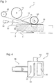
- FIG. 4 A preferred embodiment of the pressing device 20 and the energy source 30 are in FIG. 4 schematically in one Side view shown.
- the pressing device 20 and the energy source 30 are combined to form a unit 50, which can be exchanged via an interface 52 in a supply unit such as in the tool holder of a spindle unit.
- the interface 52 may be, for example, a universal interface as described in the patent application EP 0 743 139 the applicant is disclosed.
- the interchangeable unit 50 may also carry the focusing device 32 and also have a feed slot 54 for the coating material so that it can be easily fed to the pressure roller 20 and energized from the opposite side by means of the power source 30 with energy.
- a feed slot 54 for the coating material so that it can be easily fed to the pressure roller 20 and energized from the opposite side by means of the power source 30 with energy.
- an alternative or additional application of energy to the workpiece can take place.
- Such a unit is particularly well suited for stationary machines, but also for continuous machines, and allows a particularly variable and flexible operation of such machines, the number of required supply units (spindle units) can be reduced accordingly.
Description
Die Erfindung betrifft eine Vorrichtung zum Beschichten von Werkstücken, die bevorzugt zumindest abschnittsweise aus Holz, Holzwerkstoffen, Kunststoff oder dergleichen gemäß dem Oberbegriff des Anspruchs 1. Eine solche Vorrichtung ist aus der
Vorrichtungen zum Beschichten von Werkstücken der eingangs genannten Art sind beispielsweise in der Form von Kantenanleimmaschinen im Bereich der Möbel- und Bauelementindustrie seit langem bekannt. So offenbart beispielsweise die
Obgleich sich diese Technik über einen langen Zeitraum bewährt hat, lassen die in der Möbel- und Bauelementeindustrie immer weiter wachsenden Anforderungen den Wunsch nach verbesserten Lösungen für das Beschichten von Werkstücken entstehen. Wesentliche Aspekte sind hierbei einerseits die immer größer werdende Vielfalt an Beschichtungsmaterialien, die in den unterschiedlichsten Dicken und Materialien vorliegen und individuelle Lösungen erfordern. Darüber hinaus wird auch immer häufiger eine so genannte Stückzahl-1-Fertigung gefordert, bei der für jedes Werkstück ein anderes Beschichtungsmaterial vorzusehen ist. Dies erfordert eine hohe Variabilität bzw. Anpassungsfähigkeit der Beschichtungsvorrichtung.Although this technique has been proven over a long period of time, the ever increasing demands in the furniture and component industry are creating the desire for improved solutions for coating workpieces. On the one hand, essential aspects are the ever-increasing variety of coating materials, which are available in a wide variety of thicknesses and materials and require individual solutions. In addition, more and more often a so-called
Darüber hinaus kann die Handhabung und Aufbringung heißen Schmelzklebers auf das Beschichtungsmaterial zu Verunreinigungen und Störungen im Betriebsablauf führen, was die Zuverlässigkeit der Bearbeitung beeinträchtigen kann.In addition, the handling and application of hot melt adhesive to the coating material can lead to contamination and malfunction in the operation, which can affect the reliability of the processing.
Nicht zuletzt nehmen auch die Anforderungen an die Betriebsgeschwindigkeit bzw. Kapazität der Beschichtungsvorrichtungen immer weiter zu, so dass auch ein Bedarf an einer beschleunigten Arbeitsweise der Beschichtungsvorrichtung besteht.Last but not least, the demands on the operating speed or capacity of the coating devices continue to increase, so that there is also a need for an accelerated operation of the coating device.
Es ist daher Aufgabe der Erfindung, ein Beschichtungsverfahren und eine Beschichtungsvorrichtung der eingangs genannten Art bereitzustellen, die einen zuverlässigen, flexiblen und gleichzeitig zügigen Betrieb ermöglichen.It is therefore an object of the invention to provide a coating method and a coating device of the type mentioned, which allow a reliable, flexible and at the same time speedy operation.
Diese Aufgabe wird erfindungsgemäß durch eine Vorrichtung zum Beschichten von Werkstücken nach Anspruch 1 gelöst. Besonders bevorzugte Weiterbildungen der Erfindung sind in den abhängigen Ansprüchen angegeben.This object is achieved by a device for coating workpieces according to
Die Erfindung stellt eine Vorrichtung zum Beschichten von Werkstücken nach Anspruch 1 bereit. Der erfindungsgemäßen Vorrichtung liegt der Gedanke zugrunde, an der Schnittstelle zwischen Beschichtungsmaterial und Werkstück anzusetzen und den bisher zum Einsatz kommenden, vorgeheizten Schmelzkleber durch neuartige Verbindungstechniken zu ersetzen. Zu diesem Zweck ist erfindungsgemäß vorgesehen, dass die Vorrichtung zum Beschichten von Werkstücken mindestens eine Energiequelle zum Aufbringen von Energie auf ein Haftmittel bzw. haftend machbares Mittel aufweist, das eigenständig vorgesehen sein kann und/oder Teil des Beschichtungsmaterials und/oder des Werkstücks sein kann. Auf diese Weise ergeben sich deutlich weit reichendere Möglichkeiten, den Verbindungsvorgang des Beschichtungsmaterials an dem Werkstück auf die jeweiligen Anforderungen abzustimmen und so für jeden Einzelfall einen optimalen Betrieb der Beschichtungsvorrichtung zu ermöglichen. Hierdurch ergibt sich selbst bei so genannter Stückzahl-1-Fertigung eine optimale Kombination eines präzisen, flexiblen und zügigen Betriebs.The invention provides an apparatus for coating workpieces according to
Die Energiequelle ist im Rahmen der vorliegenden Erfindung als Mikrowellenquelle ausgestaltet, wobei der Begriff "Energie" im Rahmen der vorliegenden Erfindung in einem breiten Sinne aufzufassen ist.The energy source is designed in the context of the present invention as a microwave source, wherein the term "energy" in the context of the present invention is to be construed in a broad sense.
Energiequellen mit Mikrowelle arbeiten berührungslos und können auch während des Andrückens des Beschichtungsmaterials noch Energie in den Prozess einbringen. Gemäß der Erfindung ist ferner vorgesehen, dass die Andrückeinrichtung eingerichtet ist, das Beschichtungsmaterial auf eine Schmalfläche des Werkstücks aufzubringen. Somit lassen sich mit der erfindungsgemäßen Vorrichtung Werkstücke mit einer beliebigen Gestalt bei weiterhin präzisem, flexiblem und zügigem Betrieb herstellen.Microwave energy sources operate without contact and can still add energy to the process during the pressing of the coating material. According to the invention it is further provided that the pressing device is adapted to apply the coating material to a narrow surface of the workpiece. Thus, with the device according to the invention, workpieces of any desired shape can be produced with continued precise, flexible and rapid operation.
Das Beschichtungsmaterial ist im Rahmen der vorliegenden Erfindung vorzugsweise in Form eines Vorrats in der Zuführeinrichtung vorgesehen, wobei das Beschichtungsmaterial im Rahmen der vorliegenden Erfindung aus unterschiedlichsten Materialien ausgewählt sein kann. Gemäß einer Weiterbildung der Erfindung ist es dabei bevorzugt, dass das Material des Beschichtungsmaterials ausgewählt ist aus der Gruppe bestehend aus Kunststoff, Furnier, Papier, Pappe, Metall und Kombinationen hiervon.In the context of the present invention, the coating material is preferably provided in the form of a supply in the feed device, it being possible for the coating material in the context of the present invention to be selected from a very wide variety of materials. According to one embodiment of the invention, it is preferred that the material of the coating material is selected from the group consisting of plastic, veneer, paper, cardboard, metal and combinations thereof.
Gemäß einer Weiterbildung der Erfindung ist ferner vorgesehen, dass das Beschichtungsmaterial 12 zumindest abschnittsweise eine integrale oder diskrete Schicht aufweist, die durch Energiezufuhr haftende Eigenschaften entfaltet. Auf diese Weise ist es im Rahmen der Erfindung nicht mehr unbedingt erforderlich, einen herkömmlichen Haftmittelauftrag vorzusehen, sondern diese Funktion kann in die Kantenzufuhr integriert werden. Dabei ermöglicht eine vollständige Integration des Haftmittels bzw. haftend machbaren Mittels in das Beschichtungsmaterial einen sehr einfachen und zügigen Betrieb der erfindungsgemäßen Vorrichtung. Demgegenüber besitzt die Ausbildung des Haftmittels bzw. haftend machbaren Mittels als diskrete Schicht, die zu einem geeigneten Zeitpunkt mit dem Beschichtungsmaterial verbunden wird, den Vorteil einer höheren Variantenvielfalt, so muss bei der letztgenannten Ausgestaltung auch für unterschiedlichste Arten von Beschichtungsmaterialien nur eine einzelne diskrete Schicht eines Haftmittels bzw. haftend machbaren Mittels vorgehalten werden.According to one embodiment of the invention, it is further provided that the
Alternativ oder zusätzlich kann es im Rahmen der vorliegenden Erfindung jedoch weiterhin vorteilhaft sein, dass die Vorrichtung ferner mindestens eine Haftmittelbereitstellungseinrichtung aufweist, die eingerichtet ist, ein bereits haftendes oder noch durch Energiebeaufschlagung haftend zu machendes Mittel auf das Beschichtungsmaterial und/oder Werkstück aufzutragen. Hierdurch wird die Variantenvielfalt der Vorrichtung noch weiter erhöht, und es kann auch mit Kombinationen verschiedener Haftmittel gearbeitet werden, sodass mittels der erfindungsgemäßen Vorrichtung praktisch jedes Beschichtungsmaterial auf praktisch jedes Werkstück aufgebracht werden kann. Dabei ist es besonders bevorzugt, dass die Vorrichtung mindestens zwei Haftmittelbereitstellungseinrichtungen aufweist, die voneinander unterschiedliche Haftmittel bzw. haftend machbare Mittel bereitstellen.Alternatively or additionally, however, it can also be advantageous in the context of the present invention for the device to furthermore have at least one adhesive supply device which is set up to apply an agent which is already adhering or can still be bonded by applying energy to the coating material and / or workpiece. As a result, the variety of variants of the device is further increased, and it can also be used with combinations of different adhesives, so that virtually any coating material can be applied to virtually any workpiece by means of the device according to the invention. It is particularly preferred that the device has at least two adhesive supply devices, the provide each other different adhesives or adhesively feasible means.
Insbesondere bei einem Aufbringen von Beschichtungsmaterial auf eine Breitfläche des Werkstücks ist es gemäß einer Weiterbildung der Erfindung vorteilhaft, dass die mindestens eine Energiequelle verfahrbar angeordnet ist, und zwar bevorzugt quer zur Richtung einer durch die Fördereinrichtung erzeugten Relativbewegung zwischen der Andrückeinrichtung und dem jeweiligen Werkstück. Hierdurch lassen sich auch großflächige Beschichtungsmaterialien rationell mit einer einzigen bzw. einer geringen Anzahl von Energiequellen aufbringen.In particular, when applying coating material to a wide surface of the workpiece, it is advantageous according to a development of the invention that the at least one energy source is arranged movable, preferably transversely to the direction of a relative movement between the pressing device and the respective workpiece generated by the conveyor. As a result, even large-area coating materials can be applied rationally with a single or a small number of energy sources.
Die Fördereinrichtung kann im Rahmen der vorliegenden Erfindung auf unterschiedlichste Art und Weise ausgestaltet sein, beispielsweise derart, dass das jeweilige Werkstück stationär vorgesehen ist und ein oder mehrere Bauteile der Vorrichtung in Bezug auf das Werkstück verfahrbar sind. Derartige Stationärmaschinen zeichnen sich durch einen sehr geringen Platzbedarf und eine hohe Variabilität aus. Gemäß einer Weiterbildung der Erfindung ist jedoch vorgesehen, dass die Fördereinrichtung eingerichtet ist, die Werkstücke in einer Durchlaufrichtung zu fördern, wobei der Förderbetrieb kontinuierlich oder gegebenenfalls auch getaktet sein kann. Auf diese Weise wird ein besonders zügiger und störungsfreier Betrieb der erfindungsgemäßen Vorrichtung mit hohem Durchsatz erreicht.The conveyor may be configured in the context of the present invention in various ways, for example, such that the respective workpiece is provided stationary and one or more components of the device with respect to the workpiece are movable. Such stationary machines are characterized by a very small footprint and high variability. According to one embodiment of the invention, however, it is provided that the conveyor is set up to convey the workpieces in a direction of passage, wherein the conveying operation can be continuous or optionally also clocked. In this way, a particularly rapid and trouble-free operation of the device according to the invention with high throughput is achieved.
Die einzelnen Baueinheiten der erfindungsgemäßen Vorrichtung können prinzipiell als eigenständige, fest oder verfahrbar montierte Einheiten angeordnet sein. Gemäß einer Weiterbildung der Erfindung ist jedoch vorgesehen, dass zumindest die Andrückeinrichtung und die Energiequelle zu einer Einheit zusammengefasst sind, die über eine Schnittstelle in eine Versorgungseinheit wie beispielsweise in die Werkzeugaufnahme einer Spindeleinheit einwechselbar ist. Hierdurch lässt sich eine hochgradig variable und flexible Vorrichtung schaffen, mit der unterschiedlichste Werkstücke und Beschickungsmaterialien verarbeitet werden können, ohne eine übermäßig große Anzahl von Bauteilen vorzusehen. Insbesondere wird durch die Einwechselbarkeit der Einheit aus Andrückeinrichtung und Energiequelle die Anzahl der erforderlichen Antriebseinheiten vermindert, da unterschiedliche Einheiten über die gemeinsame Versorgungseinheit (beispielsweise Spindeleinheit) angetrieben und versorgt werden können.The individual structural units of the device according to the invention can in principle be arranged as independent, fixed or movably mounted units. According to one embodiment of the invention, however, it is provided that at least the pressing device and the power source are combined to form a unit, which via an interface in a supply unit such as can be exchanged in the tool holder of a spindle unit. As a result, a highly variable and flexible device can be created, with which a wide variety of workpieces and feed materials can be processed without providing an excessively large number of components. In particular, the number of required drive units is reduced by the interchangeability of the unit of pressure device and energy source, since different units on the common supply unit (for example spindle unit) can be driven and supplied.
Ferner ist gemäß einer Weiterbildung der Erfindung vorgesehen, dass die Vorrichtung eine Fokussiereinrichtung aufweist, die eingerichtet ist, die von der Energiequelle bereitgestellte Energie auf ausgewählte Bereiche des zu aktivierenden oder zu erzeugenden Haftmittels zu richten. Auf diese Weise können mehrere Effekte gleichzeitig erzielt werden. Einerseits kann der Betrieb der Vorrichtung problemlos an unterschiedliche Abmessungen des Beschichtungsmaterials abgestimmt werden, ohne dass Umbauarbeiten an der jeweiligen Energiequelle erforderlich sind. So kann die Wirkfläche punkt- oder linienförmig, aber auch flächig mit unterschiedlichen Abmessungen eingestellt werden.Furthermore, according to a development of the invention, it is provided that the device has a focusing device, which is set up to direct the energy provided by the energy source to selected regions of the adhesive to be activated or to be generated. In this way several effects can be achieved simultaneously. On the one hand, the operation of the device can be easily adapted to different dimensions of the coating material, without modification work on the respective energy source are required. Thus, the active surface point or line, but also be set flat with different dimensions.
Darüber hinaus kann über die Fokussiereinrichtung jedoch gegebenenfalls auch die Intensität der auf das Haftmittel aufgebrachten Energie variiert werden, sodass ein optimales Beschichtungsergebnis ohne Beschädigung des Beschichtungsmaterials erreicht werden kann.In addition, however, if necessary, the intensity of the energy applied to the adhesive can also be varied via the focussing device, so that an optimum coating result can be achieved without damaging the coating material.
In diesem Zusammenhang ist es besonders bevorzugt, dass die Energiequelle und/oder die Fokussiereinrichtung eingerichtet sind, zu oszillieren. Hierdurch können lokale Energiespitzen vermieden werden, und es kann eine gleichmäßige Abdeckung des mit Energie zu beaufschlagenden Bereichs bewirkt werden.In this connection, it is particularly preferred that the energy source and / or the focusing device are set up to oscillate. As a result, local energy peaks can be avoided, and a uniform coverage of the area to be energized can be effected.
Dabei ist es besonders bevorzugt, dass die Energiequelle und/oder die Fokussiereinrichtung eingerichtet sind, umso schneller zu oszillieren, je schneller die Relativbewegung gegenüber dem Werkstück ist.It is particularly preferred that the energy source and / or the focusing device are set up to oscillate the faster the faster the relative movement relative to the workpiece.
Die Fokussiereinrichtung kann die von der Energiequelle bereitgestellte Energie prinzipiell auf eine beliebige Stelle des Beschichtungsmaterials oder gegebenenfalls auch des Werkstücks oder Haftmittels richten. Gemäß einer Weiterbildung der Erfindung ist dabei jedoch vorgesehen, dass die Fokussiereinrichtung eingerichtet ist, die von der Energiequelle bereitgestellte Energie in dem Bereich unmittelbar stromaufwärts eines Andrückbereichs zu richten, in welchem das Beschichtungsmaterial an einer Oberfläche eines Werkstücks angedrückt wird. Hierdurch kann mit einer minimalen Energiemenge gearbeitet werden, was nicht nur den Energieverbrauch vermindert, sondern auch mögliche Beeinträchtigungen der mit Energie beaufschlagten Materialien minimiert.The focusing device can in principle direct the energy provided by the energy source to an arbitrary position of the coating material or optionally also of the workpiece or adhesive. According to one embodiment of the invention, however, it is provided that the focusing device is set up to direct the energy provided by the energy source in the region immediately upstream of a pressing region in which the coating material is pressed against a surface of a workpiece. As a result, it is possible to work with a minimum amount of energy, which not only reduces energy consumption but also minimizes potential damage to the energized materials.
Gemäß einer Weiterbildung der Erfindung weist die Vorrichtung ferner eine Steuereinrichtung auf, die eingerichtet ist, den Betrieb, insbesondere die Leistung der Energiequelle auf die Eigenschaften und Abmessungen des Haftmittels bzw. haftend machbaren Mittels sowie die Relativgeschwindigkeit zwischen Energiequelle und Haftmittel abzustimmen. Auf diese Weise lässt sich unter allen Betriebsbedingungen und für alle verwendeten Materialien ein optimales Beschichtungsergebnis erzielen, und zwar auch bei wirtschaftlichen Arbeitsbedingungen, in dem nämlich mit einem optimalen Energieeintrag, mit einer optimalen Haftmittelmenge, etc. gearbeitet werden kann.According to one embodiment of the invention, the device further comprises a control device, which is adapted to tune the operation, in particular the power of the energy source on the properties and dimensions of the adhesive or adhesively feasible agent and the relative speed between the energy source and adhesive. In this way, an optimal coating result can be achieved under all operating conditions and for all materials used, even in economic working conditions, namely, in which an optimum energy input, with an optimal amount of adhesive, etc. can be used.
-
Fig. 1 zeigt schematisch eine Draufsicht einer Beschichtungsvorrichtung 1 als bevorzugte Ausführungsform der vorliegenden Erfindung;Fig. 1 schematically shows a plan view of acoating apparatus 1 as a preferred embodiment of the present invention; -
Fig. 2 zeigt schematisch eine Draufsicht einer Beschichtungsvorrichtung 1 als zweite bevorzugte Ausführungsform der vorliegenden Erfindung;Fig. 2 schematically shows a plan view of acoating apparatus 1 as a second preferred embodiment of the present invention; -
Fig. 3 zeigt schematisch eine Draufsicht einer Beschichtungsvorrichtung 1 als dritte bevorzugte Ausführungsform der vorliegenden Erfindung;Fig. 3 schematically shows a plan view of acoating apparatus 1 as a third preferred embodiment of the present invention; -
Fig. 4 zeigt schematisch eine Seitenansicht einer Beschichtungseinheit für eine erfindungsgemäße Beschichtungsvorrichtung.Fig. 4 schematically shows a side view of a coating unit for a coating device according to the invention.
Bevorzugte Ausführungsformen der vorliegenden Erfindung werden nachfolgend ausführlich unter Bezugnahme auf die begleitenden Zeichnungen beschrieben.Preferred embodiments of the present invention will be described below in detail with reference to the accompanying drawings.
Eine Beschichtungsvorrichtung 1 zum Beschichten von Werkstücken 2 als bevorzugte Ausführungsform der vorliegenden Erfindung ist in
Die Beschichtungsvorrichtung 1 umfasst zunächst eine Fördereinrichtung 4, die in der vorliegenden Ausführungsform als Durchlauffördereinrichtung ausgestaltet ist, beispielsweise in Form eines Rollenförderers, Riemenförderers oder dergleichen. Dabei dient die Fördereinrichtung 4 dazu, die Werkstücke 2 in einer Durchlaufrichtung (von links nach rechts in
Neben der Fördereinrichtung 4 ist eine Zuführeinrichtung 10 zum Zuführen eines Beschichtungsmaterials 12 angeordnet, wobei es sich bei dem Beschichtungsmaterial beispielsweise um ein Kantenmaterial für eine Schmalfläche des Werkstücks, aber auch um ein Deckmaterial für eine Breitfläche oder jede andere beliebige Oberfläche des Werkstücks 2 handeln kann. Die Zuführeinrichtung 10 enthält einen Vorrat an Beschichtungsmaterial 12, das aus unterschiedlichsten Materialien bestehen kann, wie beispielsweise Kunststoff, Furnier, Papier, Pappe, Metall, etc. und vielfältigen Kombinationen hiervon. Dabei kann das Beschichtungsmaterial beispielsweise in Rollenform (ggf. in einer Kassette), aber auch in Form von Einzelabschnitten vorgesehen sein.In addition to the conveying
In der vorliegenden Ausführungsform gemäß
Die Zuführeinrichtung 10 führt das Beschichtungsmaterial 12 einer Andrückeinrichtung 20 zum Andrücken des Beschichtungsmaterials 12 an eine Oberfläche 2a des Werkstücks 2 zu. Bei der Andrückeinrichtung 20 handelt es sich in der vorliegenden Ausführungsform um eine Andrückrolle (anstelle einer Andrückrolle können beispielsweise auch Bänder, Schuhe oder dergleichen zum Einsatz kommen), die auf der Oberfläche 2a des Werkstücks 2 abrollt und auf diese Weise das Beschichtungsmaterial 12 an die Oberfläche 2a des Werkstücks 2 andrückt.The
Ferner umfasst die Beschichtungsvorrichtung 1 eine Energiequelle 30 zum Aufbringen von Energie auf das Haftmittel bzw. haftend machbare Mittel 14. Dabei ist erfindungsgemäß die Energiequelle als Mikrowellenquelle ausgebildet. Die Energiequelle 30 stellt Energie in gerichteter Form bereit und richtet diese auf das Haftmittel bzw. haftend machbare Mittel 14, das als integraler oder diskreter Teil des Beschichtungsmaterials 12 zugeführt wird.Furthermore, the
Diese gebündelte bzw. gerichtete Energie ist wie in
Im einfachsten Falle kann es sich bei der Fokussiereinrichtung 32 um eine Linse handeln. Es ist jedoch zu beachten, dass je nach Energiequelle 30 unterschiedliche Fokussiereinrichtung 32 zum Einsatz kommen können, wobei die Fokussiereinrichtung jeweils eingerichtet sein kann, die Streubreite und gegebenenfalls auch die Intensität der aufgebrachten Energie einzustellen. Auf diese Weise richtet die Fokussiereinrichtung 32 die von der Energiequelle 30 bereitgestellte Energie in den Bereich unmittelbar stromaufwärts eines Andrückbereichs 32, in welchem das Beschichtungsmaterial 12 an die Oberfläche 2a des Werkstücks 2 angedrückt wird.In the simplest case, the focusing
Dieser Betrieb der Energiequelle 30 und auch der Fokussiereinrichtung 32 wird durch eine nicht näher gezeigte Steuereinrichtung gesteuert, wobei die Steuereinrichtung insbesondere die Leistung der Energiequelle 30 auf die Eigenschaften und Abmessungen des Haftmittels bzw. haftend machbaren Mittels 14 sowie die Relativgeschwindigkeit zwischen Energiequelle 30 und Haftmittel 14 abstimmt. Zusätzlich kann die Steuereinrichtung auch Informationen von Sensoren auswerten, die den Betrieb der Beschichtungsvorrichtung überwachen, beispielsweise Sensoren, die im Bereich des Andrückbereichs 22 angeordnet sind und beispielsweise die Temperatur des aufgebrachten Beschichtungsmaterials 12 erfassen. Auf der Grundlage dieser Informationen kann die Steuereinrichtung nicht nur die Energiequelle 30, sondern gegebenenfalls auch die Fokussiereinrichtung 32 steuern.This operation of the
Dabei ist zu beachten, dass die Fokussiereinrichtung 32 in der vorliegenden Ausführungsform eingerichtet ist, bei Bedarf zu oszillieren beispielsweise in einer Richtung senkrecht zur Zeichenebene in
Ferner ist die Fokussiereinrichtung 32 in der vorliegenden Ausführungsform gemeinsam mit der Energiequelle 30 verfahrbar, und zwar in einer Richtung quer zur Durchlaufrichtung der Fördereinrichtung 4. Dies ist besonders vorteilhaft für großflächige Beschichtungsaufgaben, wie beispielsweise zur Beschichtung der Breitflächen von Werkstücken.Furthermore, the focusing
Zusätzlich oder alternativ zu einer Aktivierung eines Haftmittels bzw. haftend machbaren Mittels 14 (das in beliebiger Form zugeführt werden kann) ermöglicht die erfindungsgemäße Vorrichtung 1 jedoch auch das erfindungsgemäße Verfahren, bei welchem in dem jeweiligen Werkstück 2 enthaltenes Lignin zum Anbringen des Beschichtungsmaterials 12 an der Oberfläche 2a des Werkstücks 2 genutzt wird. Hierfür sind an der Vorrichtung 1 keine grundlegenden Modifikationen erforderlich. Allerdings wird die Energiequelle 30 hierfür, beispielsweise mithilfe der Fokussiereinrichtung 32, derart eingerichtet und eingestellt, dass in dem Material des Werkstücks 2 enthaltenes Lignin zumindest an der zu beschichtenden Oberfläche 2a des Werkstücks haftende Eigenschaften entfaltet. Dies setzt freilich voraus, dass in dem zu beschichtenden Werkstück Lignin enthalten ist, d.h. dass das Werkstück zumindest abschnittsweise aus Holz, Holzwerkstoffen oder dergleichen besteht.However, in addition or as an alternative to activating an adhesive or adhesively feasible agent 14 (which can be supplied in any desired form), the
Anschließend oder simultan zu dem Aktivieren des Lignins wird das Beschichtungsmaterial 12 an die Oberfläche 2a des Werkstücks angedrückt, sodass das Beschichtungsmaterial unter Nutzung der haftenden Eigenschaften des Lignin mit dem Werkstück verbunden wird. Insoweit bestehen hinsichtlich des Verfahrensablaufs keine grundlegenden Unterschiede zu dem oben beschriebenen Verfahren, das ausschließlich auf einem zugeführten Haftmittel bzw. haftend machbaren Mittel 14 basiert. Ferner kann, wie bereits erwähnt, die Haftwirkung des Lignin mit der Haftwirkung eines separat zugeführten Mittels 14 kombiniert werden.Subsequently or simultaneously with the activation of the lignin, the
Zur Aktivierung bzw. zum Aufschmelzen des Lignin kann die Energie der Energiequelle 30 direkt auf die zu beschichtende Oberfläche 2a aufgebracht werden. Alternativ oder zusätzlich ist es ebenso möglich, die Energie beispielsweise auf das Beschichtungsmaterial 12 aufzubringen. Diese Energie kann von dem Beschichtungsmaterial 12 beispielsweise reflektiert oder in Form von Restwärme in die Oberfläche 2a des Werkstücks eingebracht werden.To activate or melt the lignin, the energy of the
Diese Verfahrensweise, bei der die Haftwirkung des Lignin gezielt aktiviert und genutzt wird, kann auf vielfältige Weise variiert werden und insbesondere auch bei den nachfolgend beschriebenen Ausführungsformen einzeln oder in Kombination mit einem separat zugeführten Haftmittel bzw. haftend machbaren Mittel 14 zum Einsatz kommen. Ferner ist zu beachten, dass auch in dem Beschichtungsmaterial enthaltenes Lignin entsprechend aktiviert und zur Verbindung des Beschichtungsmaterials mit dem Werkstück genutzt werden kann.This procedure, in which the adhesion of the lignin is selectively activated and utilized, can be varied in many ways and, in particular in the embodiments described below, individually or in combination with a separately supplied adhesive or adhesively
Eine zweite bevorzugte Ausführungsform der erfindungsgemäßen Beschichtungsvorrichtung 1 ist in
Das derart aufgebrachte Haftmittel bzw. haftend machbare Mittel 14 wird dann ebenso durch Energiebeaufschlagung mittels der Energiequelle 30 aktiviert oder erzeugt, und zwar wiederum unmittelbar stromaufwärts eines Andrückbereichs 22.The thus-applied
Obgleich in
Eine dritte bevorzugte Ausführungsform der erfindungsgemäßen Beschichtungsvorrichtung 1 ist in
Eine bevorzugte Ausgestaltung der Andrückeinrichtung 20 und der Energiequelle 30 sind in
Die einwechselbare Einheit 50 kann ebenso die Fokussiereinrichtung 32 tragen und darüber hinaus einen Zufuhrschlitz 54 für das Beschichtungsmaterial aufweisen, damit dieses problemlos zu der Andrückwalze 20 zugeführt und von der gegenüberliegenden Seite mittels der Energiequelle 30 mit Energie beaufschlagt werden kann. Es ist jedoch zu beachten, dass auch in dieser Ausführungsform - wie generell im Rahmen der Erfindung - auch eine alternative oder zusätzliche Energiebeaufschlagung des Werkstücks erfolgen kann.The
Eine derartige Einheit eignet sich besonders gut für Stationärmaschinen, aber auch für Durchlaufmaschinen, und ermöglicht einen besonders variablen und flexiblen Betrieb derartiger Maschinen, wobei die Anzahl der benötigten Versorgungseinheiten (Spindeleinheiten) entsprechend verringert werden kann.Such a unit is particularly well suited for stationary machines, but also for continuous machines, and allows a particularly variable and flexible operation of such machines, the number of required supply units (spindle units) can be reduced accordingly.
Claims (11)
- Device (1) for coating workpieces (2) preferably consisting at least in sections of wood, wood materials, plastic, aluminium or the like, comprising:a feed device (10) for feeding a coating material (12),a pressing device (20) for pressing the coating material (12) onto a surface (2a) of a workpiece (2),a conveyor device (4) for effecting a relative movement between the pressing device (20) and the respective workpiece (2), andat least one energy source (30) for applying energy to an adhesive agent or agent (14) which can be rendered adhesive, which can be provided independently and/or can be part of the coating material (12) and/or of the workpiece (2), characterised in thatthe at least one energy source (30) is a microwave source, and the pressing device (20) is configured to apply the coating material (12) to a narrow surface area of the workpiece (2),wherein the device also comprises a control unit and sensors which monitor the operation of the coating device, wherein the control unit is configured to control an operation of the energy source (30), and is configured to evaluate information from the sensors, and the control unit is further configured to control the energy source (30) on the basis of the information from the sensors.
- Device according to claim 1, characterised in that the feed device (10) contains a supply of coating material (12), the material of which is selected from the group consisting of plastic, veneer, paper, card, metal and combinations thereof.
- Device according to one of the claims 1 and 2, characterised in that the coating material (12) has at least in sections an integral or discrete layer (14) which displays adhesive properties on the input of energy.
- Device according to one of the claims 1 to 3, characterised in that it further comprises at least one adhesive supply device (40, 42) which is configured to apply an already adhesive agent (14) or one which can be rendered adhesive to the coating material (12) and/or workpiece (2).
- Device according to claim 4, characterised in that it has at least two adhesive supply devices (40, 42) which supply different adhesive agents (14) or agents (14) which can be rendered adhesive.
- Device according to one of the claims 1 to 5, characterised in that the at least one energy source (30) is arranged moveably, preferably transversely to the direction of a relative movement between the pressing device (20) and the respective workpiece (2) generated by the conveyor device (4).
- Device according to one of the claims 1 to 6, characterised in that the conveyor device (4) is configured to transport the workpieces (2) in a throughput direction.
- Device according to one of the claims 1 to 7, characterised in that it further comprises a focusing device (32) which is configured to direct the energy supplied by the energy source (30) onto selected regions of the adhesive agent (14) which is to be activated or created.
- Device according to one of the claims 1 to 8, characterised in that the energy source (30) and/or the focusing device (32) are configured to oscillate.
- Device according to claim 9, characterised in that the energy source (30) and/or the focusing device (32) are configured to oscillate more quickly the faster the relative movement in relation to the workpiece (2).
- Device according to one of the preceding claims, characterised in that sensors are arranged in the region of the pressing region (22) and in particular register the temperature of the applied coating material (12).
Applications Claiming Priority (4)
| Application Number | Priority Date | Filing Date | Title |
|---|---|---|---|
| DE202008015878U DE202008015878U1 (en) | 2008-12-01 | 2008-12-01 | Device for coating workpieces |
| EP09002588.3A EP2191947B1 (en) | 2008-12-01 | 2009-02-24 | Method for coating workpieces |
| PCT/EP2009/066035 WO2010063668A1 (en) | 2008-12-01 | 2009-11-30 | Method and apparatus for coating workpieces |
| EP09763940.5A EP2365899B1 (en) | 2008-12-01 | 2009-11-30 | Apparatus for coating workpieces |
Related Parent Applications (1)
| Application Number | Title | Priority Date | Filing Date |
|---|---|---|---|
| EP09763940.5A Division EP2365899B1 (en) | 2008-12-01 | 2009-11-30 | Apparatus for coating workpieces |
Publications (2)
| Publication Number | Publication Date |
|---|---|
| EP3132901A1 EP3132901A1 (en) | 2017-02-22 |
| EP3132901B1 true EP3132901B1 (en) | 2019-10-23 |
Family
ID=42105528
Family Applications (3)
| Application Number | Title | Priority Date | Filing Date |
|---|---|---|---|
| EP09002588.3A Expired - Fee Related EP2191947B1 (en) | 2008-12-01 | 2009-02-24 | Method for coating workpieces |
| EP16191750.5A Active EP3132901B1 (en) | 2008-12-01 | 2009-11-30 | Method and device for coating workpieces |
| EP09763940.5A Active EP2365899B1 (en) | 2008-12-01 | 2009-11-30 | Apparatus for coating workpieces |
Family Applications Before (1)
| Application Number | Title | Priority Date | Filing Date |
|---|---|---|---|
| EP09002588.3A Expired - Fee Related EP2191947B1 (en) | 2008-12-01 | 2009-02-24 | Method for coating workpieces |
Family Applications After (1)
| Application Number | Title | Priority Date | Filing Date |
|---|---|---|---|
| EP09763940.5A Active EP2365899B1 (en) | 2008-12-01 | 2009-11-30 | Apparatus for coating workpieces |
Country Status (7)
| Country | Link |
|---|---|
| US (1) | US20120058279A1 (en) |
| EP (3) | EP2191947B1 (en) |
| CN (2) | CN102271884A (en) |
| BR (1) | BRPI0922115A2 (en) |
| DE (1) | DE202008015878U1 (en) |
| ES (2) | ES2441599T3 (en) |
| WO (1) | WO2010063668A1 (en) |
Families Citing this family (21)
| Publication number | Priority date | Publication date | Assignee | Title |
|---|---|---|---|---|
| EP2243619B2 (en) † | 2009-04-22 | 2022-03-16 | Homag Holzbearbeitungssysteme AG | Method and device for coating workpieces |
| EP2345518B1 (en) | 2010-01-18 | 2014-04-23 | Homag Holzbearbeitungssysteme AG | Method and device for coating workpieces |
| LT2622035T (en) | 2010-09-27 | 2023-06-12 | Henkel Ag & Co. Kgaa | Bonding with melt adfhesive |
| ES2416985T3 (en) * | 2010-09-27 | 2013-08-05 | Homag Holzbearbeitungssysteme Ag | Device and procedure for coating a workpiece |
| DE102012206712A1 (en) * | 2012-04-24 | 2013-10-24 | Homag Holzbearbeitungssysteme Gmbh | Method for processing workpiece used for manufacturing e.g. furniture, involves providing command acoustically input by operator using input device such as microphone to processing unit connected to control device |
| DE102013002920B4 (en) | 2013-02-21 | 2018-06-07 | Ima Klessmann Gmbh Holzbearbeitungssysteme | Bekantungsvorrichtung |
| DE102014208519A1 (en) | 2014-05-07 | 2015-11-12 | Homag Holzbearbeitungssysteme Gmbh | Processing device and processing method |
| DE102015000043A1 (en) | 2015-01-09 | 2016-07-14 | Ima Klessmann Gmbh Holzbearbeitungssysteme | Method for processing workpieces, in particular edgebands, and apparatus for carrying out the method |
| CN107708947A (en) * | 2015-04-13 | 2018-02-16 | 未来木材工机株式会社 | The manufacture method of wooden laminate |
| ITUB20150532A1 (en) | 2015-04-21 | 2016-10-21 | Scm Group Spa | EDGE BANDING DEVICE |
| ITUB20152366A1 (en) * | 2015-07-21 | 2017-01-21 | Biesse Spa | MACHINE FOR EDGEING WOODEN PANELS OR THE LIKE |
| DE102017208422A1 (en) * | 2017-05-18 | 2018-11-22 | Homag Gmbh | processing device |
| DE102017122701A1 (en) * | 2017-09-29 | 2019-04-04 | Homag Gmbh | Coating device and coating method |
| US10124536B1 (en) * | 2018-01-08 | 2018-11-13 | Oav Equipment & Tools, Inc. | Edge banding machine |
| DE102018125609B4 (en) * | 2018-10-16 | 2021-11-25 | Surteco Gmbh | Method and device for fastening an edging strip |
| DE102019113932A1 (en) * | 2019-05-24 | 2020-11-26 | Homag Gmbh | Method for coating a component and coating device |
| US11660631B2 (en) * | 2021-05-05 | 2023-05-30 | Oav Equipment And Tools, Inc. | Glue applying mechanism of edge banding machine with glue quantity regulator |
| US11541415B2 (en) * | 2021-05-26 | 2023-01-03 | Oav Equipment And Tools, Inc. | Glue applying mechanism of edge banding machine for applying glue to workpiece having oblique surface and edge banding machine using the glue applying mechanism |
| DE102021117813A1 (en) | 2021-07-09 | 2023-01-12 | Homag Gmbh | Process for coating a workpiece, coating device and computer program for setting up a coating device |
| DE102021124866B3 (en) * | 2021-09-27 | 2022-10-20 | Ima Schelling Deutschland Gmbh | Cutting device, edge processing device and method for cutting through a coating material |
| DE102022113672A1 (en) | 2022-05-31 | 2023-11-30 | Homag Gmbh | Processing device with a coating unit and method for applying adhesive |
Citations (2)
| Publication number | Priority date | Publication date | Assignee | Title |
|---|---|---|---|---|
| DE1085625B (en) * | 1958-02-27 | 1960-07-21 | Mikrowellen Ges M B H Deutsche | Microwave emitter, preferably for edge banding |
| WO2009026977A1 (en) * | 2007-08-24 | 2009-03-05 | Rehau Ag + Co | Edge trim for pieces of furniture |
Family Cites Families (26)
| Publication number | Priority date | Publication date | Assignee | Title |
|---|---|---|---|---|
| SE309900B (en) * | 1963-09-16 | 1969-04-08 | Svenska Flaektfabriken Ab | |
| GB1123526A (en) * | 1966-03-30 | 1968-08-14 | Ernst Ludvig Back | A method for sealing cellulose or lignocellulosic materials together or to other materials |
| US3676283A (en) * | 1969-08-14 | 1972-07-11 | Grace W R & Co | Laminate and process for laminating with polythiol polyene reaction product |
| BE759393A (en) * | 1970-04-09 | 1971-04-30 | Dhj Ind Inc | CONNECTION METHOD AND APPARATUS BY APPLICATION OF |
| DE3447592A1 (en) | 1984-12-28 | 1986-07-10 | Hornberger Maschinenbaugesellschaft mbH & Co KG, 7294 Schopfloch | Device for applying hot-melt adhesive to continuously moved workpieces |
| JPH03205A (en) * | 1989-05-26 | 1991-01-07 | Norin Suisansyo Shinrin Sogo Kenkyusho | High speed bonding method of wood by heating surface |
| CN1067399A (en) * | 1991-06-05 | 1992-12-30 | 蛇口招商无胶人造板新技术有限公司 | Lignocellulosic materials is made glue-free artificial board's commercial run and equipment |
| US5607536A (en) * | 1992-10-30 | 1997-03-04 | Tikka-System Oy | Method and apparatus for coating objects with a plastic film |
| DE19517808A1 (en) | 1995-05-15 | 1996-11-21 | Homag Maschinenbau Ag | Machining center with a spindle unit for holding machining tools and machining units for wood and plastic materials |
| US5643983A (en) * | 1995-08-30 | 1997-07-01 | Ashland Inc. | Moisture curable 100% solids one component plywood adhesive |
| DE19742825B4 (en) * | 1997-09-27 | 2010-01-21 | Hohenloher Spezialmöbelwerk Schaffitzel GmbH + Co. | Method for applying a ruling and panel with a ruling |
| DE19955575B4 (en) * | 1999-11-18 | 2010-04-08 | Brandt Kantentechnik Gmbh | Method and device for adhering a cover material to workpiece surfaces of continuously moving or stationarily arranged plate- or strip-shaped workpieces |
| DE10122573A1 (en) * | 2001-05-09 | 2002-11-14 | Winkler & Duennebier Ag | Gluing station for a machine for manufacturing envelopes, shipping bags and the like |
| US7066680B2 (en) * | 2001-12-04 | 2006-06-27 | Integrated Paving Concepts Inc. | Method of forming an inlaid pattern in an asphalt surface |
| US20030217807A1 (en) * | 2002-01-25 | 2003-11-27 | Leif Lesmann | Method and apparatus for gluing |
| KR100448328B1 (en) * | 2002-03-19 | 2004-09-10 | 이강 | Dry film laminating apparatus and method thereof using the microwave |
| DE10342723B4 (en) * | 2003-09-16 | 2005-12-15 | Delle Vedove Maschinenbau Gmbh | heat exchanger device |
| AT503091A2 (en) * | 2004-02-04 | 2007-07-15 | Thoma & Harms Holz Gmbh | METHOD FOR COMPRESSING A SURFACE OF A WOODEN WORKPIECE AND DEVICE THEREFOR |
| JP2006231621A (en) * | 2005-02-23 | 2006-09-07 | Eidai Co Ltd | Manufacturing method of veneer laminated decorative material and clamping board used therein |
| PL1800813T3 (en) * | 2005-11-23 | 2012-05-31 | Homag Holzbearbeitungssysteme Ag | method and device for coating components |
| JP4274573B2 (en) * | 2006-03-24 | 2009-06-10 | 株式会社森林資源利用促進研究所 | Wooden container and manufacturing method thereof |
| SE529747C2 (en) * | 2006-04-10 | 2007-11-13 | Carmen Cristescu | Binder-free process for producing lignocellulosic laminate by hot pressing, and thereby producing laminate |
| DE102006021171A1 (en) * | 2006-05-06 | 2007-11-08 | W. Döllken & Co. GmbH | cover strip |
| US7494272B2 (en) * | 2006-06-27 | 2009-02-24 | Applied Materials, Inc. | Dynamic surface annealing using addressable laser array with pyrometry feedback |
| US8540906B2 (en) * | 2007-06-14 | 2013-09-24 | Aji Co., Ltd. | Method of molding, process for producing lens, molding apparatus, process for producing stamper, master production apparatus, stamper production system, and stamper production apparatus |
| US8945333B2 (en) * | 2008-07-21 | 2015-02-03 | Karl W. Niemann Gmbh & Co. Kg | Method for applying edge strips onto narrow surfaces of in particular plate-shaped work pieces and work pieces obtained in said manner |
-
2008
- 2008-12-01 DE DE202008015878U patent/DE202008015878U1/en not_active Expired - Lifetime
-
2009
- 2009-02-24 ES ES09002588.3T patent/ES2441599T3/en active Active
- 2009-02-24 EP EP09002588.3A patent/EP2191947B1/en not_active Expired - Fee Related
- 2009-11-30 ES ES09763940.5T patent/ES2607655T3/en active Active
- 2009-11-30 EP EP16191750.5A patent/EP3132901B1/en active Active
- 2009-11-30 CN CN200980153888XA patent/CN102271884A/en active Pending
- 2009-11-30 CN CN201611051958.9A patent/CN106426431A/en active Pending
- 2009-11-30 EP EP09763940.5A patent/EP2365899B1/en active Active
- 2009-11-30 WO PCT/EP2009/066035 patent/WO2010063668A1/en active Application Filing
- 2009-11-30 US US13/132,183 patent/US20120058279A1/en not_active Abandoned
- 2009-11-30 BR BRPI0922115A patent/BRPI0922115A2/en not_active Application Discontinuation
Patent Citations (2)
| Publication number | Priority date | Publication date | Assignee | Title |
|---|---|---|---|---|
| DE1085625B (en) * | 1958-02-27 | 1960-07-21 | Mikrowellen Ges M B H Deutsche | Microwave emitter, preferably for edge banding |
| WO2009026977A1 (en) * | 2007-08-24 | 2009-03-05 | Rehau Ag + Co | Edge trim for pieces of furniture |
Also Published As
| Publication number | Publication date |
|---|---|
| ES2607655T3 (en) | 2017-04-03 |
| ES2441599T3 (en) | 2014-02-05 |
| BRPI0922115A2 (en) | 2016-01-05 |
| WO2010063668A1 (en) | 2010-06-10 |
| EP2191947B1 (en) | 2013-10-16 |
| CN106426431A (en) | 2017-02-22 |
| CN102271884A (en) | 2011-12-07 |
| EP2365899B1 (en) | 2016-10-12 |
| US20120058279A1 (en) | 2012-03-08 |
| DE202008015878U1 (en) | 2010-04-15 |
| EP3132901A1 (en) | 2017-02-22 |
| EP2365899A1 (en) | 2011-09-21 |
| EP2191947A1 (en) | 2010-06-02 |
Similar Documents
| Publication | Publication Date | Title |
|---|---|---|
| EP3132901B1 (en) | Method and device for coating workpieces | |
| EP2243619B2 (en) | Method and device for coating workpieces | |
| EP2345518B1 (en) | Method and device for coating workpieces | |
| EP3461608A1 (en) | Coating device and coating method | |
| EP1751005B1 (en) | Method and device for packaging flat articles | |
| EP2251171B1 (en) | Device for coating workpieces | |
| EP3075503B1 (en) | Edging device and method | |
| WO2001089809A1 (en) | Sealing | |
| EP2065217A1 (en) | Device and method for sampling a workpiece using web like materials | |
| EP3976329A1 (en) | Method for coating a component, and coating apparatus | |
| EP3033205B1 (en) | Coating unit | |
| EP1867488A1 (en) | Device for patterning the surface of workpieces | |
| EP2401220A1 (en) | Method and device for adhering an edge of a laminar object | |
| EP1632347A1 (en) | Method and apparatus for joining flat materials | |
| WO2021018644A1 (en) | Device and method for attaching edge bands | |
| EP3551404A1 (en) | Device and method for coating a workpiece | |
| EP3318378A1 (en) | Method for coating uneven surfaces, device and component | |
| DE102010004092A1 (en) | Workpiece edge creating device, has press member laid out in edge tape with pulsating pressure, where edge tape is advanced into region of pressure zone by relative movement of workpiece and edge tape to narrow side of workpiece | |
| DE102013008022B3 (en) | Apparatus for smoothing narrow surfaces of furniture manufacturing panels e.g. particle board used in furniture industry, has spring element that is contacted with coated or uncoated narrow surface of furniture manufacturing plate | |
| EP3546070B1 (en) | Device for applying a flowable material to a substrate | |
| DE3713773C2 (en) | Method and device for the continuous gluing of veneer strips on the edges of plate-shaped workpieces | |
| WO2005009702A1 (en) | Method and device for producing wood-based panels | |
| EP3653353B1 (en) | Device and method for coating a workpiece | |
| DE10303285A1 (en) | Application method for applying glue on packing material, involves applying glue on packing material in accordance with packing material conveying speed, thickness of glue layer to be formed on packing material, and glue viscosity | |
| CH637059A5 (en) | EDGE BANDING MACHINE. |
Legal Events
| Date | Code | Title | Description |
|---|---|---|---|
| PUAI | Public reference made under article 153(3) epc to a published international application that has entered the european phase |
Free format text: ORIGINAL CODE: 0009012 |
|
| STAA | Information on the status of an ep patent application or granted ep patent |
Free format text: STATUS: THE APPLICATION HAS BEEN PUBLISHED |
|
| AC | Divisional application: reference to earlier application |
Ref document number: 2365899 Country of ref document: EP Kind code of ref document: P |
|
| AK | Designated contracting states |
Kind code of ref document: A1 Designated state(s): AT BE BG CH CY CZ DE DK EE ES FI FR GB GR HR HU IE IS IT LI LT LU LV MC MK MT NL NO PL PT RO SE SI SK SM TR |
|
| STAA | Information on the status of an ep patent application or granted ep patent |
Free format text: STATUS: REQUEST FOR EXAMINATION WAS MADE |
|
| 17P | Request for examination filed |
Effective date: 20170529 |
|
| RBV | Designated contracting states (corrected) |
Designated state(s): AT BE BG CH CY CZ DE DK EE ES FI FR GB GR HR HU IE IS IT LI LT LU LV MC MK MT NL NO PL PT RO SE SI SK SM TR |
|
| STAA | Information on the status of an ep patent application or granted ep patent |
Free format text: STATUS: EXAMINATION IS IN PROGRESS |
|
| 17Q | First examination report despatched |
Effective date: 20171201 |
|
| GRAP | Despatch of communication of intention to grant a patent |
Free format text: ORIGINAL CODE: EPIDOSNIGR1 |
|
| STAA | Information on the status of an ep patent application or granted ep patent |
Free format text: STATUS: GRANT OF PATENT IS INTENDED |
|
| INTG | Intention to grant announced |
Effective date: 20190621 |
|
| GRAS | Grant fee paid |
Free format text: ORIGINAL CODE: EPIDOSNIGR3 |
|
| GRAA | (expected) grant |
Free format text: ORIGINAL CODE: 0009210 |
|
| STAA | Information on the status of an ep patent application or granted ep patent |
Free format text: STATUS: THE PATENT HAS BEEN GRANTED |
|
| AC | Divisional application: reference to earlier application |
Ref document number: 2365899 Country of ref document: EP Kind code of ref document: P |
|
| AK | Designated contracting states |
Kind code of ref document: B1 Designated state(s): AT BE BG CH CY CZ DE DK EE ES FI FR GB GR HR HU IE IS IT LI LT LU LV MC MK MT NL NO PL PT RO SE SI SK SM TR |
|
| REG | Reference to a national code |
Ref country code: GB Ref legal event code: FG4D Free format text: NOT ENGLISH |
|
| REG | Reference to a national code |
Ref country code: CH Ref legal event code: EP |
|
| REG | Reference to a national code |
Ref country code: IE Ref legal event code: FG4D Free format text: LANGUAGE OF EP DOCUMENT: GERMAN |
|
| REG | Reference to a national code |
Ref country code: DE Ref legal event code: R096 Ref document number: 502009015998 Country of ref document: DE |
|
| REG | Reference to a national code |
Ref country code: AT Ref legal event code: REF Ref document number: 1193175 Country of ref document: AT Kind code of ref document: T Effective date: 20191115 |
|
| REG | Reference to a national code |
Ref country code: NL Ref legal event code: MP Effective date: 20191023 |
|
| REG | Reference to a national code |
Ref country code: LT Ref legal event code: MG4D |
|
| PG25 | Lapsed in a contracting state [announced via postgrant information from national office to epo] |
Ref country code: NO Free format text: LAPSE BECAUSE OF FAILURE TO SUBMIT A TRANSLATION OF THE DESCRIPTION OR TO PAY THE FEE WITHIN THE PRESCRIBED TIME-LIMIT Effective date: 20200123 Ref country code: PL Free format text: LAPSE BECAUSE OF FAILURE TO SUBMIT A TRANSLATION OF THE DESCRIPTION OR TO PAY THE FEE WITHIN THE PRESCRIBED TIME-LIMIT Effective date: 20191023 Ref country code: GR Free format text: LAPSE BECAUSE OF FAILURE TO SUBMIT A TRANSLATION OF THE DESCRIPTION OR TO PAY THE FEE WITHIN THE PRESCRIBED TIME-LIMIT Effective date: 20200124 Ref country code: LV Free format text: LAPSE BECAUSE OF FAILURE TO SUBMIT A TRANSLATION OF THE DESCRIPTION OR TO PAY THE FEE WITHIN THE PRESCRIBED TIME-LIMIT Effective date: 20191023 Ref country code: SE Free format text: LAPSE BECAUSE OF FAILURE TO SUBMIT A TRANSLATION OF THE DESCRIPTION OR TO PAY THE FEE WITHIN THE PRESCRIBED TIME-LIMIT Effective date: 20191023 Ref country code: BG Free format text: LAPSE BECAUSE OF FAILURE TO SUBMIT A TRANSLATION OF THE DESCRIPTION OR TO PAY THE FEE WITHIN THE PRESCRIBED TIME-LIMIT Effective date: 20200123 Ref country code: FI Free format text: LAPSE BECAUSE OF FAILURE TO SUBMIT A TRANSLATION OF THE DESCRIPTION OR TO PAY THE FEE WITHIN THE PRESCRIBED TIME-LIMIT Effective date: 20191023 Ref country code: PT Free format text: LAPSE BECAUSE OF FAILURE TO SUBMIT A TRANSLATION OF THE DESCRIPTION OR TO PAY THE FEE WITHIN THE PRESCRIBED TIME-LIMIT Effective date: 20200224 Ref country code: NL Free format text: LAPSE BECAUSE OF FAILURE TO SUBMIT A TRANSLATION OF THE DESCRIPTION OR TO PAY THE FEE WITHIN THE PRESCRIBED TIME-LIMIT Effective date: 20191023 Ref country code: LT Free format text: LAPSE BECAUSE OF FAILURE TO SUBMIT A TRANSLATION OF THE DESCRIPTION OR TO PAY THE FEE WITHIN THE PRESCRIBED TIME-LIMIT Effective date: 20191023 |
|
| PG25 | Lapsed in a contracting state [announced via postgrant information from national office to epo] |
Ref country code: HR Free format text: LAPSE BECAUSE OF FAILURE TO SUBMIT A TRANSLATION OF THE DESCRIPTION OR TO PAY THE FEE WITHIN THE PRESCRIBED TIME-LIMIT Effective date: 20191023 Ref country code: IS Free format text: LAPSE BECAUSE OF FAILURE TO SUBMIT A TRANSLATION OF THE DESCRIPTION OR TO PAY THE FEE WITHIN THE PRESCRIBED TIME-LIMIT Effective date: 20200224 |
|
| REG | Reference to a national code |
Ref country code: CH Ref legal event code: PL |
|
| REG | Reference to a national code |
Ref country code: DE Ref legal event code: R097 Ref document number: 502009015998 Country of ref document: DE |
|
| PG2D | Information on lapse in contracting state deleted |
Ref country code: IS |
|
| PG25 | Lapsed in a contracting state [announced via postgrant information from national office to epo] |
Ref country code: MC Free format text: LAPSE BECAUSE OF FAILURE TO SUBMIT A TRANSLATION OF THE DESCRIPTION OR TO PAY THE FEE WITHIN THE PRESCRIBED TIME-LIMIT Effective date: 20191023 Ref country code: ES Free format text: LAPSE BECAUSE OF FAILURE TO SUBMIT A TRANSLATION OF THE DESCRIPTION OR TO PAY THE FEE WITHIN THE PRESCRIBED TIME-LIMIT Effective date: 20191023 Ref country code: CZ Free format text: LAPSE BECAUSE OF FAILURE TO SUBMIT A TRANSLATION OF THE DESCRIPTION OR TO PAY THE FEE WITHIN THE PRESCRIBED TIME-LIMIT Effective date: 20191023 Ref country code: RO Free format text: LAPSE BECAUSE OF FAILURE TO SUBMIT A TRANSLATION OF THE DESCRIPTION OR TO PAY THE FEE WITHIN THE PRESCRIBED TIME-LIMIT Effective date: 20191023 Ref country code: EE Free format text: LAPSE BECAUSE OF FAILURE TO SUBMIT A TRANSLATION OF THE DESCRIPTION OR TO PAY THE FEE WITHIN THE PRESCRIBED TIME-LIMIT Effective date: 20191023 Ref country code: CH Free format text: LAPSE BECAUSE OF NON-PAYMENT OF DUE FEES Effective date: 20191130 Ref country code: DK Free format text: LAPSE BECAUSE OF FAILURE TO SUBMIT A TRANSLATION OF THE DESCRIPTION OR TO PAY THE FEE WITHIN THE PRESCRIBED TIME-LIMIT Effective date: 20191023 Ref country code: LI Free format text: LAPSE BECAUSE OF NON-PAYMENT OF DUE FEES Effective date: 20191130 Ref country code: LU Free format text: LAPSE BECAUSE OF NON-PAYMENT OF DUE FEES Effective date: 20191130 Ref country code: IS Free format text: LAPSE BECAUSE OF FAILURE TO SUBMIT A TRANSLATION OF THE DESCRIPTION OR TO PAY THE FEE WITHIN THE PRESCRIBED TIME-LIMIT Effective date: 20200223 |
|
| REG | Reference to a national code |
Ref country code: BE Ref legal event code: MM Effective date: 20191130 |
|
| PLBE | No opposition filed within time limit |
Free format text: ORIGINAL CODE: 0009261 |
|
| STAA | Information on the status of an ep patent application or granted ep patent |
Free format text: STATUS: NO OPPOSITION FILED WITHIN TIME LIMIT |
|
| PG25 | Lapsed in a contracting state [announced via postgrant information from national office to epo] |
Ref country code: SM Free format text: LAPSE BECAUSE OF FAILURE TO SUBMIT A TRANSLATION OF THE DESCRIPTION OR TO PAY THE FEE WITHIN THE PRESCRIBED TIME-LIMIT Effective date: 20191023 Ref country code: SK Free format text: LAPSE BECAUSE OF FAILURE TO SUBMIT A TRANSLATION OF THE DESCRIPTION OR TO PAY THE FEE WITHIN THE PRESCRIBED TIME-LIMIT Effective date: 20191023 |
|
| GBPC | Gb: european patent ceased through non-payment of renewal fee |
Effective date: 20200123 |
|
| 26N | No opposition filed |
Effective date: 20200724 |
|
| PG25 | Lapsed in a contracting state [announced via postgrant information from national office to epo] |
Ref country code: GB Free format text: LAPSE BECAUSE OF NON-PAYMENT OF DUE FEES Effective date: 20200123 Ref country code: FR Free format text: LAPSE BECAUSE OF NON-PAYMENT OF DUE FEES Effective date: 20191223 Ref country code: IE Free format text: LAPSE BECAUSE OF NON-PAYMENT OF DUE FEES Effective date: 20191130 |
|
| PG25 | Lapsed in a contracting state [announced via postgrant information from national office to epo] |
Ref country code: BE Free format text: LAPSE BECAUSE OF NON-PAYMENT OF DUE FEES Effective date: 20191130 Ref country code: SI Free format text: LAPSE BECAUSE OF FAILURE TO SUBMIT A TRANSLATION OF THE DESCRIPTION OR TO PAY THE FEE WITHIN THE PRESCRIBED TIME-LIMIT Effective date: 20191023 |
|
| PG25 | Lapsed in a contracting state [announced via postgrant information from national office to epo] |
Ref country code: CY Free format text: LAPSE BECAUSE OF FAILURE TO SUBMIT A TRANSLATION OF THE DESCRIPTION OR TO PAY THE FEE WITHIN THE PRESCRIBED TIME-LIMIT Effective date: 20191023 |
|
| PG25 | Lapsed in a contracting state [announced via postgrant information from national office to epo] |
Ref country code: MT Free format text: LAPSE BECAUSE OF FAILURE TO SUBMIT A TRANSLATION OF THE DESCRIPTION OR TO PAY THE FEE WITHIN THE PRESCRIBED TIME-LIMIT Effective date: 20191023 Ref country code: HU Free format text: LAPSE BECAUSE OF FAILURE TO SUBMIT A TRANSLATION OF THE DESCRIPTION OR TO PAY THE FEE WITHIN THE PRESCRIBED TIME-LIMIT; INVALID AB INITIO Effective date: 20091130 |
|
| PG25 | Lapsed in a contracting state [announced via postgrant information from national office to epo] |
Ref country code: TR Free format text: LAPSE BECAUSE OF FAILURE TO SUBMIT A TRANSLATION OF THE DESCRIPTION OR TO PAY THE FEE WITHIN THE PRESCRIBED TIME-LIMIT Effective date: 20191023 |
|
| PG25 | Lapsed in a contracting state [announced via postgrant information from national office to epo] |
Ref country code: MK Free format text: LAPSE BECAUSE OF FAILURE TO SUBMIT A TRANSLATION OF THE DESCRIPTION OR TO PAY THE FEE WITHIN THE PRESCRIBED TIME-LIMIT Effective date: 20191023 |
|
| P01 | Opt-out of the competence of the unified patent court (upc) registered |
Effective date: 20230529 |
|
| PGFP | Annual fee paid to national office [announced via postgrant information from national office to epo] |
Ref country code: IT Payment date: 20231115 Year of fee payment: 15 Ref country code: DE Payment date: 20231106 Year of fee payment: 15 Ref country code: AT Payment date: 20231128 Year of fee payment: 15 |