EP3098541B1 - Co2 water heater - Google Patents
Co2 water heater Download PDFInfo
- Publication number
- EP3098541B1 EP3098541B1 EP15754816.5A EP15754816A EP3098541B1 EP 3098541 B1 EP3098541 B1 EP 3098541B1 EP 15754816 A EP15754816 A EP 15754816A EP 3098541 B1 EP3098541 B1 EP 3098541B1
- Authority
- EP
- European Patent Office
- Prior art keywords
- heat
- water
- source
- circulation path
- heat exchanger
- Prior art date
- Legal status (The legal status is an assumption and is not a legal conclusion. Google has not performed a legal analysis and makes no representation as to the accuracy of the status listed.)
- Active
Links
- XLYOFNOQVPJJNP-UHFFFAOYSA-N water Substances O XLYOFNOQVPJJNP-UHFFFAOYSA-N 0.000 title claims description 105
- VTVVPPOHYJJIJR-UHFFFAOYSA-N carbon dioxide;hydrate Chemical compound O.O=C=O VTVVPPOHYJJIJR-UHFFFAOYSA-N 0.000 claims description 81
- 239000000498 cooling water Substances 0.000 claims description 61
- 230000001105 regulatory effect Effects 0.000 claims description 28
- CURLTUGMZLYLDI-UHFFFAOYSA-N Carbon dioxide Chemical compound O=C=O CURLTUGMZLYLDI-UHFFFAOYSA-N 0.000 description 230
- 229910002092 carbon dioxide Inorganic materials 0.000 description 115
- RYGMFSIKBFXOCR-UHFFFAOYSA-N Copper Chemical compound [Cu] RYGMFSIKBFXOCR-UHFFFAOYSA-N 0.000 description 9
- 238000001816 cooling Methods 0.000 description 9
- 229910052802 copper Inorganic materials 0.000 description 9
- 239000010949 copper Substances 0.000 description 9
- 239000007788 liquid Substances 0.000 description 6
- 238000009423 ventilation Methods 0.000 description 6
- 238000005406 washing Methods 0.000 description 6
- 230000005611 electricity Effects 0.000 description 4
- 238000010586 diagram Methods 0.000 description 3
- 238000007710 freezing Methods 0.000 description 3
- 230000008014 freezing Effects 0.000 description 3
- 230000001276 controlling effect Effects 0.000 description 2
- 238000004378 air conditioning Methods 0.000 description 1
- 239000001569 carbon dioxide Substances 0.000 description 1
- 230000000694 effects Effects 0.000 description 1
- 230000020169 heat generation Effects 0.000 description 1
- 238000010438 heat treatment Methods 0.000 description 1
- 238000004519 manufacturing process Methods 0.000 description 1
- 239000000463 material Substances 0.000 description 1
- 231100000252 nontoxic Toxicity 0.000 description 1
- 230000003000 nontoxic effect Effects 0.000 description 1
- 239000003507 refrigerant Substances 0.000 description 1
Images

Classifications
-
- F—MECHANICAL ENGINEERING; LIGHTING; HEATING; WEAPONS; BLASTING
- F25—REFRIGERATION OR COOLING; COMBINED HEATING AND REFRIGERATION SYSTEMS; HEAT PUMP SYSTEMS; MANUFACTURE OR STORAGE OF ICE; LIQUEFACTION SOLIDIFICATION OF GASES
- F25B—REFRIGERATION MACHINES, PLANTS OR SYSTEMS; COMBINED HEATING AND REFRIGERATION SYSTEMS; HEAT PUMP SYSTEMS
- F25B5/00—Compression machines, plants or systems, with several evaporator circuits, e.g. for varying refrigerating capacity
- F25B5/02—Compression machines, plants or systems, with several evaporator circuits, e.g. for varying refrigerating capacity arranged in parallel
-
- F—MECHANICAL ENGINEERING; LIGHTING; HEATING; WEAPONS; BLASTING
- F24—HEATING; RANGES; VENTILATING
- F24D—DOMESTIC- OR SPACE-HEATING SYSTEMS, e.g. CENTRAL HEATING SYSTEMS; DOMESTIC HOT-WATER SUPPLY SYSTEMS; ELEMENTS OR COMPONENTS THEREFOR
- F24D17/00—Domestic hot-water supply systems
- F24D17/02—Domestic hot-water supply systems using heat pumps
-
- F—MECHANICAL ENGINEERING; LIGHTING; HEATING; WEAPONS; BLASTING
- F24—HEATING; RANGES; VENTILATING
- F24H—FLUID HEATERS, e.g. WATER OR AIR HEATERS, HAVING HEAT-GENERATING MEANS, e.g. HEAT PUMPS, IN GENERAL
- F24H4/00—Fluid heaters characterised by the use of heat pumps
- F24H4/02—Water heaters
-
- F—MECHANICAL ENGINEERING; LIGHTING; HEATING; WEAPONS; BLASTING
- F25—REFRIGERATION OR COOLING; COMBINED HEATING AND REFRIGERATION SYSTEMS; HEAT PUMP SYSTEMS; MANUFACTURE OR STORAGE OF ICE; LIQUEFACTION SOLIDIFICATION OF GASES
- F25B—REFRIGERATION MACHINES, PLANTS OR SYSTEMS; COMBINED HEATING AND REFRIGERATION SYSTEMS; HEAT PUMP SYSTEMS
- F25B40/00—Subcoolers, desuperheaters or superheaters
-
- F—MECHANICAL ENGINEERING; LIGHTING; HEATING; WEAPONS; BLASTING
- F25—REFRIGERATION OR COOLING; COMBINED HEATING AND REFRIGERATION SYSTEMS; HEAT PUMP SYSTEMS; MANUFACTURE OR STORAGE OF ICE; LIQUEFACTION SOLIDIFICATION OF GASES
- F25B—REFRIGERATION MACHINES, PLANTS OR SYSTEMS; COMBINED HEATING AND REFRIGERATION SYSTEMS; HEAT PUMP SYSTEMS
- F25B41/00—Fluid-circulation arrangements
- F25B41/20—Disposition of valves, e.g. of on-off valves or flow control valves
- F25B41/24—Arrangement of shut-off valves for disconnecting a part of the refrigerant cycle, e.g. an outdoor part
-
- F—MECHANICAL ENGINEERING; LIGHTING; HEATING; WEAPONS; BLASTING
- F25—REFRIGERATION OR COOLING; COMBINED HEATING AND REFRIGERATION SYSTEMS; HEAT PUMP SYSTEMS; MANUFACTURE OR STORAGE OF ICE; LIQUEFACTION SOLIDIFICATION OF GASES
- F25B—REFRIGERATION MACHINES, PLANTS OR SYSTEMS; COMBINED HEATING AND REFRIGERATION SYSTEMS; HEAT PUMP SYSTEMS
- F25B49/00—Arrangement or mounting of control or safety devices
- F25B49/02—Arrangement or mounting of control or safety devices for compression type machines, plants or systems
-
- F—MECHANICAL ENGINEERING; LIGHTING; HEATING; WEAPONS; BLASTING
- F25—REFRIGERATION OR COOLING; COMBINED HEATING AND REFRIGERATION SYSTEMS; HEAT PUMP SYSTEMS; MANUFACTURE OR STORAGE OF ICE; LIQUEFACTION SOLIDIFICATION OF GASES
- F25B—REFRIGERATION MACHINES, PLANTS OR SYSTEMS; COMBINED HEATING AND REFRIGERATION SYSTEMS; HEAT PUMP SYSTEMS
- F25B9/00—Compression machines, plants or systems, in which the refrigerant is air or other gas of low boiling point
- F25B9/002—Compression machines, plants or systems, in which the refrigerant is air or other gas of low boiling point characterised by the refrigerant
- F25B9/008—Compression machines, plants or systems, in which the refrigerant is air or other gas of low boiling point characterised by the refrigerant the refrigerant being carbon dioxide
-
- F—MECHANICAL ENGINEERING; LIGHTING; HEATING; WEAPONS; BLASTING
- F25—REFRIGERATION OR COOLING; COMBINED HEATING AND REFRIGERATION SYSTEMS; HEAT PUMP SYSTEMS; MANUFACTURE OR STORAGE OF ICE; LIQUEFACTION SOLIDIFICATION OF GASES
- F25B—REFRIGERATION MACHINES, PLANTS OR SYSTEMS; COMBINED HEATING AND REFRIGERATION SYSTEMS; HEAT PUMP SYSTEMS
- F25B2309/00—Gas cycle refrigeration machines
- F25B2309/06—Compression machines, plants or systems characterised by the refrigerant being carbon dioxide
- F25B2309/061—Compression machines, plants or systems characterised by the refrigerant being carbon dioxide with cycle highest pressure above the supercritical pressure
-
- F—MECHANICAL ENGINEERING; LIGHTING; HEATING; WEAPONS; BLASTING
- F25—REFRIGERATION OR COOLING; COMBINED HEATING AND REFRIGERATION SYSTEMS; HEAT PUMP SYSTEMS; MANUFACTURE OR STORAGE OF ICE; LIQUEFACTION SOLIDIFICATION OF GASES
- F25B—REFRIGERATION MACHINES, PLANTS OR SYSTEMS; COMBINED HEATING AND REFRIGERATION SYSTEMS; HEAT PUMP SYSTEMS
- F25B2339/00—Details of evaporators; Details of condensers
- F25B2339/04—Details of condensers
- F25B2339/047—Water-cooled condensers
-
- F—MECHANICAL ENGINEERING; LIGHTING; HEATING; WEAPONS; BLASTING
- F25—REFRIGERATION OR COOLING; COMBINED HEATING AND REFRIGERATION SYSTEMS; HEAT PUMP SYSTEMS; MANUFACTURE OR STORAGE OF ICE; LIQUEFACTION SOLIDIFICATION OF GASES
- F25B—REFRIGERATION MACHINES, PLANTS OR SYSTEMS; COMBINED HEATING AND REFRIGERATION SYSTEMS; HEAT PUMP SYSTEMS
- F25B2400/00—General features or devices for refrigeration machines, plants or systems, combined heating and refrigeration systems or heat-pump systems, i.e. not limited to a particular subgroup of F25B
- F25B2400/01—Heaters
-
- F—MECHANICAL ENGINEERING; LIGHTING; HEATING; WEAPONS; BLASTING
- F25—REFRIGERATION OR COOLING; COMBINED HEATING AND REFRIGERATION SYSTEMS; HEAT PUMP SYSTEMS; MANUFACTURE OR STORAGE OF ICE; LIQUEFACTION SOLIDIFICATION OF GASES
- F25B—REFRIGERATION MACHINES, PLANTS OR SYSTEMS; COMBINED HEATING AND REFRIGERATION SYSTEMS; HEAT PUMP SYSTEMS
- F25B2400/00—General features or devices for refrigeration machines, plants or systems, combined heating and refrigeration systems or heat-pump systems, i.e. not limited to a particular subgroup of F25B
- F25B2400/04—Refrigeration circuit bypassing means
- F25B2400/0415—Refrigeration circuit bypassing means for the receiver
-
- F—MECHANICAL ENGINEERING; LIGHTING; HEATING; WEAPONS; BLASTING
- F25—REFRIGERATION OR COOLING; COMBINED HEATING AND REFRIGERATION SYSTEMS; HEAT PUMP SYSTEMS; MANUFACTURE OR STORAGE OF ICE; LIQUEFACTION SOLIDIFICATION OF GASES
- F25B—REFRIGERATION MACHINES, PLANTS OR SYSTEMS; COMBINED HEATING AND REFRIGERATION SYSTEMS; HEAT PUMP SYSTEMS
- F25B2400/00—General features or devices for refrigeration machines, plants or systems, combined heating and refrigeration systems or heat-pump systems, i.e. not limited to a particular subgroup of F25B
- F25B2400/16—Receivers
-
- F—MECHANICAL ENGINEERING; LIGHTING; HEATING; WEAPONS; BLASTING
- F25—REFRIGERATION OR COOLING; COMBINED HEATING AND REFRIGERATION SYSTEMS; HEAT PUMP SYSTEMS; MANUFACTURE OR STORAGE OF ICE; LIQUEFACTION SOLIDIFICATION OF GASES
- F25B—REFRIGERATION MACHINES, PLANTS OR SYSTEMS; COMBINED HEATING AND REFRIGERATION SYSTEMS; HEAT PUMP SYSTEMS
- F25B2600/00—Control issues
- F25B2600/02—Compressor control
- F25B2600/021—Inverters therefor
-
- F—MECHANICAL ENGINEERING; LIGHTING; HEATING; WEAPONS; BLASTING
- F25—REFRIGERATION OR COOLING; COMBINED HEATING AND REFRIGERATION SYSTEMS; HEAT PUMP SYSTEMS; MANUFACTURE OR STORAGE OF ICE; LIQUEFACTION SOLIDIFICATION OF GASES
- F25B—REFRIGERATION MACHINES, PLANTS OR SYSTEMS; COMBINED HEATING AND REFRIGERATION SYSTEMS; HEAT PUMP SYSTEMS
- F25B2600/00—Control issues
- F25B2600/25—Control of valves
- F25B2600/2523—Receiver valves
-
- F—MECHANICAL ENGINEERING; LIGHTING; HEATING; WEAPONS; BLASTING
- F25—REFRIGERATION OR COOLING; COMBINED HEATING AND REFRIGERATION SYSTEMS; HEAT PUMP SYSTEMS; MANUFACTURE OR STORAGE OF ICE; LIQUEFACTION SOLIDIFICATION OF GASES
- F25B—REFRIGERATION MACHINES, PLANTS OR SYSTEMS; COMBINED HEATING AND REFRIGERATION SYSTEMS; HEAT PUMP SYSTEMS
- F25B2700/00—Sensing or detecting of parameters; Sensors therefor
- F25B2700/19—Pressures
- F25B2700/193—Pressures of the compressor
- F25B2700/1933—Suction pressures
-
- F—MECHANICAL ENGINEERING; LIGHTING; HEATING; WEAPONS; BLASTING
- F25—REFRIGERATION OR COOLING; COMBINED HEATING AND REFRIGERATION SYSTEMS; HEAT PUMP SYSTEMS; MANUFACTURE OR STORAGE OF ICE; LIQUEFACTION SOLIDIFICATION OF GASES
- F25B—REFRIGERATION MACHINES, PLANTS OR SYSTEMS; COMBINED HEATING AND REFRIGERATION SYSTEMS; HEAT PUMP SYSTEMS
- F25B2700/00—Sensing or detecting of parameters; Sensors therefor
- F25B2700/19—Pressures
- F25B2700/197—Pressures of the evaporator
-
- F—MECHANICAL ENGINEERING; LIGHTING; HEATING; WEAPONS; BLASTING
- F25—REFRIGERATION OR COOLING; COMBINED HEATING AND REFRIGERATION SYSTEMS; HEAT PUMP SYSTEMS; MANUFACTURE OR STORAGE OF ICE; LIQUEFACTION SOLIDIFICATION OF GASES
- F25B—REFRIGERATION MACHINES, PLANTS OR SYSTEMS; COMBINED HEATING AND REFRIGERATION SYSTEMS; HEAT PUMP SYSTEMS
- F25B2700/00—Sensing or detecting of parameters; Sensors therefor
- F25B2700/21—Temperatures
- F25B2700/2115—Temperatures of a compressor or the drive means therefor
- F25B2700/21151—Temperatures of a compressor or the drive means therefor at the suction side of the compressor
-
- F—MECHANICAL ENGINEERING; LIGHTING; HEATING; WEAPONS; BLASTING
- F25—REFRIGERATION OR COOLING; COMBINED HEATING AND REFRIGERATION SYSTEMS; HEAT PUMP SYSTEMS; MANUFACTURE OR STORAGE OF ICE; LIQUEFACTION SOLIDIFICATION OF GASES
- F25B—REFRIGERATION MACHINES, PLANTS OR SYSTEMS; COMBINED HEATING AND REFRIGERATION SYSTEMS; HEAT PUMP SYSTEMS
- F25B2700/00—Sensing or detecting of parameters; Sensors therefor
- F25B2700/21—Temperatures
- F25B2700/2116—Temperatures of a condenser
- F25B2700/21161—Temperatures of a condenser of the fluid heated by the condenser
-
- Y—GENERAL TAGGING OF NEW TECHNOLOGICAL DEVELOPMENTS; GENERAL TAGGING OF CROSS-SECTIONAL TECHNOLOGIES SPANNING OVER SEVERAL SECTIONS OF THE IPC; TECHNICAL SUBJECTS COVERED BY FORMER USPC CROSS-REFERENCE ART COLLECTIONS [XRACs] AND DIGESTS
- Y02—TECHNOLOGIES OR APPLICATIONS FOR MITIGATION OR ADAPTATION AGAINST CLIMATE CHANGE
- Y02B—CLIMATE CHANGE MITIGATION TECHNOLOGIES RELATED TO BUILDINGS, e.g. HOUSING, HOUSE APPLIANCES OR RELATED END-USER APPLICATIONS
- Y02B30/00—Energy efficient heating, ventilation or air conditioning [HVAC]
- Y02B30/70—Efficient control or regulation technologies, e.g. for control of refrigerant flow, motor or heating
Definitions
- the present invention relates to a CO2 water heater constituting a heat pump cycle using CO2 as a heat exchange medium, more specifically to a CO2 water heater operable in operating modes including an air heat source mode and a water heat source mode which are switchable to each other.
- CO2 is a natural medium having a relatively small impact on the global environment. CO2 is non-toxic and non-flammable. In addition, when compressed to high pressure by a compressor, CO2 gets into the supercritical state (a state under a temperature and a pressure above the critical point, where distinct liquid and gas phases do not exist), in which CO2 is likely to transfer a high-temperature heat to e.g. water in nature. Thus, a water heater using CO2 as the heat exchange medium is capable of making water having a high temperature of about 90°C.
- the present applicant has developed a CO2 water heater using discharged warm water from a plant as a heat source and CO2 as a heat exchange medium to form a heat pump cycle (Patent Document 1). It is possible to make water by using the water-heat-source CO2 water heater, and further it is possible to use cold water, which is secondarily generated, for cooling plant facilities or a cold water load.
- Patent Documents 2 and 3 The air-heat-source CO2 water heater is capable of making hot water at a high COP when discharged warm water is not available.
- US 2006/218948 , US 2011/041523 , and DE 10 2006 054828 disclose a cooling and/or heating system in which carbon dioxide may be used as refrigerant.
- US 2006/218948 discloses the preamble of claim 1.
- a water-heat-source CO2 water heater and an air-heat-source CO2 water heater are different in the amount of use of CO2.
- CO2 is used in a hot gas state.
- the capacities of CO2 used in the water-heat-source CO2 water heater and the air-heat-source CO2 water heater are largely different from each other. Therefore, it has been difficult to provide a CO2 water heater capable of switching operation between water-heat-source operation and air-heat-source operation.
- a CO2 water heater comprises: a CO2 circulation path configured to allow CO2 to circulate therein; a compressor, a gas cooler and an expansion valve, each of which is provided on the CO2 circulation path; a bypass passage connected to the CO2 circulation path and provided so as to bypass the expansion valve; and a CO2 reservoir tank for storing CO2 at least in a hot gas state, preferably in a supercritical state, and a first flow regulating valve, each of which is provided on the bypass passage.
- the CO2 circulation path has two CO2 branch passages branched in a parallel manner between the compressor and a connecting portion of the bypass passage on a downstream side of the expansion valve.
- the CO2 water heater further comprises: an air-heat-source heat exchanger provided on one of the CO2 branch passages; a water-heat-source heat exchanger provided on the other one of the CO2 branch passages; a flow path switching mechanism configured to switch a CO2 flow path to the one or the other one of the CO2 branch passages; and an air flow forming part for forming an air flow to be introduced to the air-heat-source heat exchanger.
- the capacity of the air-heat-source heat exchanger is set to be larger than the capacity of the water-heat-source heat exchanger because of e.g. the difference in the heat exchange efficiency with respect to the heat exchange medium between air and water, and thus, the CO2 circulation amount is set to be larger in the air heat source mode than in the water heat source mode.
- the difference in the CO2 circulation amount may be adjusted by adjusting the amount of CO2 stored in the CO2 reservoir tank.
- the CO2 water heater in a time period when cooling is necessary, by operating the CO2 water heater in the water heat source mode, it is possible to make warm water by using heat-source water such as discharged warm water from a plant, and to use cool water to be secondarily generated for cooling of plant facilities. In a time period, such as winter or night, when cooling is not necessary, it is possible to switch the operating mode to the air heat source mode to operate the CO2 water heater so as only to make warm water.
- the CO2 water heater When operated in the water heat source mode, the CO2 water heater may be used as an alternative to a cold water chiller unit, and accordingly it is possible to largely reduce the operating time of the cold water chiller unit or to make the cold water chiller unit unnecessary.
- the electricity usage may not exceed a certain amount.
- the CO2 water heater further comprises an openable and closable shutoff valve on each of the CO2 branch passages at an outlet of the air-heat-source heat exchanger and the water-heat-source heat exchanger, respectively.
- CO2 remaining in the heat exchanger provided on the other CO2 branch passage may be introduced into the CO2 circulation path.
- the above shutoff valve provided, whereby it is possible to solve the problem.
- the operating mode is switched from the air heat source mode to the water heat source mode, by permitting CO2 to remain in the air-heat-source heat exchanger, it is possible to smoothly switch the operating mode.
- the CO2 water heater further comprises: a first pressure sensor and a first temperature sensor, each of which is provided on the CO2 circulation path at an inlet of the compressor; a superheat degree calculating part configured to calculate a superheat degree of CO2 from detected values by the first pressure sensor and the first temperature sensor; and a first controller configured to control an opening degree of the first flow regulating valve on the basis of the superheat degree calculated by the superheat degree calculating part to control a superheat degree of CO2 to be introduced to the compressor.
- the CO2 output pressure of the compressor may be likely to increase due to excess CO2 circulation amount.
- the opening degree of the expansion valve may be increased to an opening degree set at the switching, whereby it may be likely that CO2 as a liquid is introduced into the compressor.
- the CO2 water heater further comprises: a heat source water circulation path connected to the water-heat-source heat exchanger; a heat source water pump provided on the heat source water circulation path and configured to supply heat source water to the water-heat-source heat exchanger; a second pressure sensor provided on the CO2 branch passage at an inlet of the water-heat-source heat exchanger; and a second controller configured to allow the heat source water pump to operate when a CO2 saturation temperature corresponding to a detected value by the second pressure sensor becomes 0 degree or lower.
- the CO2 water heater further comprises: a cooling water circulation path connected to the gas cooler; a heat exchanger which the cooling water circulation path and a secondary cooling water circulation path are connected to and which is configured to exchange heat between a cooling water circulating in the cooling water circulation path and a secondary cooling water circulating in the secondary cooling water circulation path; a second flow regulating valve provided on the secondary cooling water circulation path; a second temperature sensor provided on the cooling water circulation path at an outlet of the heat exchanger; a third temperature sensor provided on the secondary cooling water circulation path at the outlet of the heat exchanger; a third controller configured to control an opening degree of the second flow regulating valve, on the basis of detected values by the second temperature sensor and the third temperature sensor, so that a COP of the CO2 water heater becomes a setting value.
- the CO2 water heater further comprises an auxiliary blower for forming a cold air flow between components of the CO2 water heater.
- an auxiliary blower for forming a cold air flow between components of the CO2 water heater.
- the present invention it is possible to seamlessly switch the operating mode of the CO2 water heater between the water heat source mode and the air heat source mode, thereby to improve the operating rate of the CO2 water heater and to suppress increase in the electricity usage.
- a CO2 water heater 10 includes a housing 12 and a CO2 circulation path 14 provided in the housing 12, and on the CO2 circulation path 14, a compressor 16, a gas cooler 18, an expansion valve 20, an air-heat-source heat exchangers (22a, 22b), a water-heat-source heat exchanger 24 and so on are provided.
- the compressor 16 includes a driving motor 16a and an inverter 16b to enable a variable rotational speed of the driving motor 16a.
- CO2 in the supercritical state is discharged from the compressor 16 to the CO2 circulation path 14, and then is sent to the gas cooler 18.
- a cooling water circulation path 70 is connected to the gas cooler 18, by which CO2 is cooled with cooling water circulating in the cooling water circulation path 70.
- CO2 having passed through the gas cooler 18 is cooled by heat change in the internal heat exchanger 28 with CO2 having passed through the air-heat-source heat exchangers (22a, 22b) or the water-heat-source heat exchanger 24, and then is depressurized through the expansion valve 20.
- the CO2 circulation path 14 branches into CO2 branch passages 14b and 14c at a branching portion 14a on an outlet side of the expansion valve 20.
- the air-heat-source heat exchangers (22a, 22b) are provided on the CO2 branch passage 14b, and the water-heat-source heat exchanger 24 is provided on the CO2 branch passage 14c.
- the CO2 branch passages (14b, 14c) join each other at a joining portion 14d on outlet sides of the air-heat-source heat exchangers (22a, 22b) and the water-heat-source heat exchanger 24.
- CO2 having joined at the joining portion 14d is heated in the internal heat exchanger 28 with CO2 from the gas cooler 18, and then is introduced into the inlet (not shown) of the compressor 16.
- COP of the CO2 water heater 10 may be increased because of the internal heat exchanger 28.
- a bypass passage 30 is connected to the CO2 circulation path 14 between the gas cooler 18 and the internal heat exchanger 28 and between the expansion valve 20 and the branching portion 14a.
- a supercritical tank 32 for storing excess CO2 is provided on the bypass passage 30, and flow regulating valves (34, 35) are provided on the bypass passage 30 at an inlet and an outlet of the supercritical tank 32, respectively.
- the supercritical tank 32 has a heater 36. In the supercritical tank 32, the temperature and the pressure are maintained above the critical point of CO2, and CO2 stored in the supercritical tank 32 is maintained in the supercritical state.
- the air-heat-source heat exchangers 22a and 22b have the same configuration.
- the air-heat-source heat exchangers (22a, 22b) have copper tubes 40 provided in a parallel manner with a space, and the both ends of the copper tubes 40 are connected to headers 42, respectively.
- Plate-like radiator fins 44 are provided on a surface of the cupper tubes, in a parallel manner along a direction perpendicular to the extending direction of the copper tubes 40.
- the headers 42 of the air-heat-source heat exchanger 22a and the headers 42 of the air-heat-source heat exchanger 22b are connected to the CO2 branch passage 14b in a parallel manner.
- CO2 flows from the CO2 branch passage 14b to the copper tubes 40 via the headers 42. Spaces are formed around the copper tubes 40, and an air flow is formed by a blower 46 provided on the housing 12. CO2 flowing in the copper tubes 40 receives heat of the air flow.
- the blower 46 has an inverter 46b which enables variable rotational speed of the driving motor 46a.
- An electromagnetic valve 48 is provided on the CO2 branch passage 14b at inlets of the air-heat-source heat exchangers (22a, 22b), and an electromagnetic valve 50 is provided on the CO2 branch passage 14c at an inlet of the water-heat-source heat exchanger 24.
- An motor operated ball valve52 is provided on the CO2 branch passage 14b at outlets of the air-heat-source heat exchangers (22a, 22b), and an motor operated ball valve54 is provided on the CO2 branch passage 14c at an outlet of the water-heat-source heat exchanger 24.
- the motor operated ball valves (52, 54) are capable of completely shutting off the CO2 branch passage 14b or 14c when closed.
- a pressure sensor 56 and a temperature sensor 58 are provided at an inlet of the compressor 16.
- a heat source water circulation path 60 is connected to the water-heat-source heat exchanger 24, and the other end of the heat source water circulation path 60 is connected to a heat source water tank 62.
- heat source water such as discharged warm water from a plant is stored.
- the heat source water stored in the heat source water tank 62 is sent to the water-heat-source heat exchanger 24 by the heat source water pump 64 provide on the heat source water circulation path 60 and is cooled by heat exchange with CO2 in the water-heat-source heat exchanger 24.
- the cooled heat source water is sent back to the heat source water tank 62, and is used as a cold heat source for a cold water load.
- a pressure sensor 66 is provided at the inlet of the water-heat-source heat exchanger 24.
- the cooling water circulation path 70 is connected to the gas cooler 18, and the other end of the cooling water circulation path 70 is connected to a heat exchanger 72.
- a secondary cooling water circulation path 74 is connected to the heat exchanger 72.
- a flow regulating valve 76 such as an motor operated valve is provided on the cooling water circulation path 70, and a flow regulating valve 78 having the same configuration as the flow regulating valve 76 is provided on the secondary cooling water circulation path 74.
- a temperature sensor 80 composed of e.g. a resistance temperature detector is provided on the cooling water circulation path 70 at an outlet of the heat exchanger, and a temperature sensor 82 having the same configuration as the temperature sensor 80 is provided on the secondary cooling water circulation path 74 at an outlet of the heat exchanger.
- Cooling water circulating in the cooling water circulation path 70 is heated by the gas cooler 18 with CO2.
- the cooling water heated by the gas cooler 18 heats the secondary cooling water in the heat exchanger 72.
- the secondary cooling water heated by the heat exchanger 72 is used as heat source water for other uses.
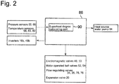
- an auxiliary ventilation fan 84 and a control panel 86 having a built-in control device 88 (see Fig. 2 ) for controlling operation of the CO2 water heater are provided.
- the ventilation fan 84 enables ventilation in the housing 12.
- the blower 46 is not operated. Accordingly, the temperature in the housing 12 may be increased by a heat released by the components.
- the ventilation fan 84 may be operated during operation in the water heat source mode to have the internal space of the housing ventilated thereby to prevent temperature increase.
- a control system for the CO2 water heater 10 will now be described with reference to Fig. 2 .
- detected values by the pressure sensors (55, 66) and temperature sensors (58, 80, 82) are inputted to the control device 88.
- the control device 88 controls operation of the inverters (16b, 46b) and the heat source water pump 64, and controls opening degrees of the expansion valve 20, the electromagnetic valves (48, 50), the flow regulating valves (34, 35, 76, 78) and the motor operated ball valves (52, 54).
- the electromagnetic valve 48 and the motor operated ball valve 52 are opened and the electromagnetic valve 50 and the motor operated ball valve 54 are closed, and the blower 46 is started to operate, and an air flow flowing on the surface of the copper tubes 40 of the air-heat-source heat exchangers (22a, 22b) is thereby formed.
- CO2 having passed through the expansion valve 20 and thus having a reduced pressure absorbs heat for its evaporative latent heat from an air flow a in the air-heat-source heat exchangers (22a, 22b).
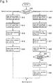
- Fig. 3 is a flowchart of an operation of switching the operating mode of the CO2 water heater 10 to an air heat source mode or a water heat source mode.
- operation steps S12 to S20 are carried out.
- the copper tubes 40 of the air-heat-source heat exchangers (22a, 22b) are formed to have a large capacity so that the CO2 circulation amount in the CO2 circulation path is larger than in the case of operation in the water heat source mode.
- the flow regulating valve 35 is opened so as to provide a suitable CO2 circulation amount for operation in the air heat source mode (S16).
- operation steps S22 to S34 are carried out.
- CO2 circulation amount becomes excessive so that the CO2 output pressure of the compressor is likely to increase.
- the opening degree of the expansion valve 20 is increased to its set opening degree to suppress increase in the output pressure of the compressor (S26).
- control device 88 has a superheat degree calculating part 90 which obtains, from a detected value by the pressure sensor 56, CO2 saturation temperature corresponding to the detected value, and which calculates a superheat degree of CO2 to be introduced into the compressor 16 from a difference between the obtained saturation temperature and a detected value by the temperature sensor 58 (S27).
- a CO2 amount to be stored in the supercritical tank 32 to provide an appropriate superheat degree to suppress liquid back and the flow regulating valve 34 is opened to store excessive CO2 in the supercritical tank 32 (S28).
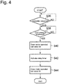
- Fig. 4 is a flowchart of an operation of equalizing a pressure to prevent pressure increase of CO2 in the water-heat-source heat exchanger 24 when it is stopped.
- S36 when the water-heat-source heat exchanger 24 is stopped (S36), if a CO2 pressure in the water-heat-source heat exchanger 24 is relatively high (S38), the motor operated ball valve 54 is opened to decrease the CO2 pressure (S40). Then a delay timer is activated (S42), and after a lapse of a set period of time after the opening of the motor operated ball valve 54, the motor operated ball valve 54 is closed (S44).
- the heat source water pump 64 is started to operate by the control device 88 to prevent the heat source water in the water-heat-source heat exchanger 24 from freezing.
- CO2 having received heat from the air flow a in the air-heat-source heat exchangers (22a, 22b) to have an increased potential heat is cooled by the gas cooler 18 with cooling water circulating in the cooling water circulation path 70.
- the detected values by the temperature sensors (80, 82) are inputted to the control device 88, and the control device 88 controls the opening degrees of the flow regulating valves (76, 78) so that the cooling water circulating in the cooling water circulation path 70 and the secondary cooling water circulating in the secondary cooling water circulation path 74 have desired temperatures, respectively.
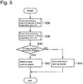
- Fig. 5 is a flowchart of an operation of the flow regulating valves (76, 78) by the control device 88.
- the flow regulating valve 76 is preliminarily maintained at a set opening degree with which a high COP is obtainable.
- PID calculation primary opening degree calculation: S36.
- an opening degree of the flow regulating valve 78 with which COP of the CO2 water heater 10 becomes higher is obtained through PID calculation (secondary opening degree calculation: S38). Then, the primary opening degree and the secondary opening degree are compared with each other (S40), and the larger one of the two is selected (S42 and S44).
- the control device 88 it is possible to seamlessly switch the operating mode to the air heat source mode or the water heat source mode without stopping the operation of the CO2 water heater 10. Accordingly, in a time period when cooling is needed, the CO2 water heater may be operated in the water heat source mode to obtain cold water which may be used for e.g. cooling of a plant facility, and in a time period when cooling is not needed such as winter or night, the operating mode may be switched to the air heat source mode to obtain warm water, whereby it is possible to improve the operating rate of the CO2 water heater 10.
- one CO2 water heater 10 may be operated in the two operating modes, increase in the electricity usage may be suppressed. Further, since it is possible to flexibly switch the operating modes taking into consideration the cold or hot heat load or the electric power condition, the CO2 water heater 10 may be easily introduced to an existing facility.
- the difference in the CO2 circulation amount between the air heat source mode and the water heat source mode may be adjusted by adjusting the amount of CO2 stored in the supercritical tank 32.
- the motor operated ball valve 52 is provided, by storing CO2 in the air-heat-source heat exchangers (22a, 22b) having a relatively large capacity during operation in the water heat source mode, it is possible to rapidly remove excess CO2 from the CO2 circulation path 14, whereby it is possible to rapidly switch the operating mode from the air heat source mode to the water heat source mode.
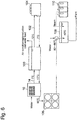
- a CO2 water heater 10 and a cold water tank 100 are connected to each other via a secondary cooling water circulation path 74.
- Secondary cooling water generated by the CO2 water heater 10 is stored in the cold water tank 100.
- the secondary cooling water stored in the cold water tank 100 may be used for air conditioning or for a cold load of a production facility.
- a part of the secondary cooling water used for a cold water load to have an increased temperature is sent to a cold water chiller 104 via a tertiary cooling water circulation path 102.
- the secondary cooling water sent to the cold water chiller 104 is cooled by the chiller 104, and then is sent back to the cold water tank 100.
- a heat source water having a temperature increased to about 90°C by a water-heat-source heat exchanger 24 of the CO2 water heater is sent to a hot-water supply tank 106.
- the warm water stored in the hot-water supply tank 106 is sent to a washing warm water tank 108 and then is supplied as washing warm water to e.g. a plant facility.
- the washing warn water stored in the washing warm water tank 108 may be maintained warm with excess steam generated by the steam boiler 110.
- the CO2 water heater 10 may be used as an alternative to the cold water chiller 104 during operation in the water heat source mode, it is possible to largely reduce the operating time of the cold water chiller 104 or to make the cold water chiller 104 unnecessary. Further, according to the above embodiment, it is possible to utilize the generated warm water as washing warm water for a plant facility.
- a CO2 water heater which is capable of seamlessly switching operating mode between operation with a water heat source and operation with an air heat source.
Priority Applications (1)
| Application Number | Priority Date | Filing Date | Title |
|---|---|---|---|
| PL15754816T PL3098541T3 (pl) | 2014-02-27 | 2015-02-10 | Podgrzewacz wody CO2 |
Applications Claiming Priority (2)
| Application Number | Priority Date | Filing Date | Title |
|---|---|---|---|
| JP2014037563A JP6301684B2 (ja) | 2014-02-27 | 2014-02-27 | Co2給湯器 |
| PCT/JP2015/053707 WO2015129456A1 (ja) | 2014-02-27 | 2015-02-10 | Co2給湯器 |
Publications (3)
| Publication Number | Publication Date |
|---|---|
| EP3098541A1 EP3098541A1 (en) | 2016-11-30 |
| EP3098541A4 EP3098541A4 (en) | 2017-03-15 |
| EP3098541B1 true EP3098541B1 (en) | 2018-06-06 |
Family
ID=54008779
Family Applications (1)
| Application Number | Title | Priority Date | Filing Date |
|---|---|---|---|
| EP15754816.5A Active EP3098541B1 (en) | 2014-02-27 | 2015-02-10 | Co2 water heater |
Country Status (11)
| Country | Link |
|---|---|
| EP (1) | EP3098541B1 (ko) |
| JP (1) | JP6301684B2 (ko) |
| KR (1) | KR101831547B1 (ko) |
| AU (1) | AU2015224225B2 (ko) |
| CL (1) | CL2016001572A1 (ko) |
| DK (1) | DK3098541T3 (ko) |
| ES (1) | ES2677253T3 (ko) |
| HU (1) | HUE038590T2 (ko) |
| MX (1) | MX2016010343A (ko) |
| PL (1) | PL3098541T3 (ko) |
| WO (1) | WO2015129456A1 (ko) |
Families Citing this family (9)
| Publication number | Priority date | Publication date | Assignee | Title |
|---|---|---|---|---|
| CN107614985B (zh) * | 2015-05-26 | 2020-04-14 | 三菱电机株式会社 | 热泵热水供给系统 |
| US10830515B2 (en) * | 2015-10-21 | 2020-11-10 | Mitsubishi Electric Research Laboratories, Inc. | System and method for controlling refrigerant in vapor compression system |
| JP6742721B2 (ja) * | 2015-12-24 | 2020-08-19 | 株式会社前川製作所 | クーラユニット |
| CN105890165B (zh) * | 2016-05-18 | 2018-11-16 | Tcl空调器(中山)有限公司 | 热水机系统及其控制方法 |
| JP2020079650A (ja) * | 2017-02-21 | 2020-05-28 | 株式会社前川製作所 | ヒートポンプ装置の制御方法及びヒートポンプ装置 |
| US10234158B2 (en) * | 2017-03-06 | 2019-03-19 | Mitsubishi Electric Research Laboratories, Inc. | Coordinated operation of multiple space-conditioning systems |
| CN109708307A (zh) * | 2018-11-20 | 2019-05-03 | 东莞市风火轮热能科技有限公司 | 超低温co2热泵热水装置 |
| US11519655B2 (en) | 2020-07-31 | 2022-12-06 | Photon Vault, Llc | Thermal energy storage and retrieval systems and methods |
| US11428476B2 (en) | 2020-09-04 | 2022-08-30 | Photon Vault, Llc | Thermal energy storage and retrieval system |
Family Cites Families (17)
| Publication number | Priority date | Publication date | Assignee | Title |
|---|---|---|---|---|
| JPH0297847A (ja) * | 1988-10-03 | 1990-04-10 | Mitsubishi Electric Corp | 多室対応分離形空気調和機 |
| JP2006125769A (ja) * | 2004-10-29 | 2006-05-18 | Denso Corp | ヒートポンプサイクル装置 |
| JP2006283989A (ja) * | 2005-03-31 | 2006-10-19 | Sanyo Electric Co Ltd | 冷暖房システム |
| JP5011713B2 (ja) | 2005-11-22 | 2012-08-29 | 株式会社デンソー | ヒートポンプ式給湯装置 |
| JP4431755B2 (ja) * | 2006-04-11 | 2010-03-17 | 株式会社前川製作所 | 給湯装置の運転方法 |
| JP5140398B2 (ja) * | 2007-11-30 | 2013-02-06 | 三洋電機株式会社 | 冷凍装置 |
| JP5035024B2 (ja) | 2008-02-29 | 2012-09-26 | ダイキン工業株式会社 | 空気調和装置および冷媒量判定方法 |
| CN102132112A (zh) * | 2008-05-14 | 2011-07-20 | 开利公司 | 制冷剂蒸汽压缩系统中的充注量管理 |
| JP2010012949A (ja) * | 2008-07-03 | 2010-01-21 | Calsonic Kansei Corp | 車両用空気調和システム |
| JP5529432B2 (ja) * | 2009-03-30 | 2014-06-25 | 三菱重工業株式会社 | ヒートポンプ装置 |
| JP5426239B2 (ja) * | 2009-06-08 | 2014-02-26 | 株式会社前川製作所 | 給湯装置及びその運転方法 |
| JP5368175B2 (ja) | 2009-06-08 | 2013-12-18 | 株式会社前川製作所 | 給湯器 |
| JP2011002207A (ja) | 2009-06-22 | 2011-01-06 | Mayekawa Mfg Co Ltd | 給湯器 |
| JP2012037203A (ja) * | 2010-08-11 | 2012-02-23 | Fuji Electric Co Ltd | 電子機器の冷却・排熱回収システム |
| JP2012177523A (ja) | 2011-02-25 | 2012-09-13 | Mayekawa Mfg Co Ltd | Co2給湯器 |
| JP5434955B2 (ja) * | 2011-04-28 | 2014-03-05 | 三菱電機株式会社 | ヒートポンプ給湯機 |
| JP2014020766A (ja) * | 2012-07-23 | 2014-02-03 | Mayekawa Mfg Co Ltd | Co2給湯器 |
-
2014
- 2014-02-27 JP JP2014037563A patent/JP6301684B2/ja active Active
-
2015
- 2015-02-10 PL PL15754816T patent/PL3098541T3/pl unknown
- 2015-02-10 ES ES15754816.5T patent/ES2677253T3/es active Active
- 2015-02-10 MX MX2016010343A patent/MX2016010343A/es active IP Right Grant
- 2015-02-10 AU AU2015224225A patent/AU2015224225B2/en active Active
- 2015-02-10 DK DK15754816.5T patent/DK3098541T3/en active
- 2015-02-10 EP EP15754816.5A patent/EP3098541B1/en active Active
- 2015-02-10 HU HUE15754816A patent/HUE038590T2/hu unknown
- 2015-02-10 KR KR1020167026186A patent/KR101831547B1/ko active IP Right Grant
- 2015-02-10 WO PCT/JP2015/053707 patent/WO2015129456A1/ja active Application Filing
-
2016
- 2016-06-17 CL CL2016001572A patent/CL2016001572A1/es unknown
Non-Patent Citations (1)
| Title |
|---|
| None * |
Also Published As
| Publication number | Publication date |
|---|---|
| EP3098541A4 (en) | 2017-03-15 |
| PL3098541T3 (pl) | 2018-09-28 |
| JP2015161465A (ja) | 2015-09-07 |
| KR20160124882A (ko) | 2016-10-28 |
| DK3098541T3 (en) | 2018-07-23 |
| ES2677253T3 (es) | 2018-07-31 |
| KR101831547B1 (ko) | 2018-02-26 |
| MX2016010343A (es) | 2016-11-11 |
| EP3098541A1 (en) | 2016-11-30 |
| AU2015224225A1 (en) | 2016-07-14 |
| WO2015129456A1 (ja) | 2015-09-03 |
| CL2016001572A1 (es) | 2017-03-03 |
| AU2015224225B2 (en) | 2017-10-26 |
| JP6301684B2 (ja) | 2018-03-28 |
| HUE038590T2 (hu) | 2018-10-29 |
Similar Documents
| Publication | Publication Date | Title |
|---|---|---|
| EP3098541B1 (en) | Co2 water heater | |
| JP5604190B2 (ja) | 蓄熱システム | |
| WO2010109632A1 (ja) | 温度調整装置、流体供給システム、暖房システム、温度調整装置の取付方法及び流体供給方法 | |
| JP5121747B2 (ja) | 地中熱ヒートポンプ装置 | |
| KR101208234B1 (ko) | 온수 공급용 히트펌프시스템 및 그 제어방법 | |
| KR102184235B1 (ko) | 액체 온조 장치 및 온도 제어 시스템 | |
| KR100852344B1 (ko) | 공기 조화 장치 | |
| JP5810042B2 (ja) | 給湯暖房システム | |
| JP6689801B2 (ja) | 太陽熱空調システム | |
| JP5746104B2 (ja) | 給湯暖房システム | |
| JP2010181088A (ja) | ヒートポンプ装置 | |
| JP5166840B2 (ja) | ヒートポンプシステム | |
| WO2019073591A1 (ja) | 空気調和システム | |
| JP6116093B2 (ja) | 熱源システム | |
| KR101236597B1 (ko) | 다용도 공기조화시스템 | |
| KR101215014B1 (ko) | 지열 냉난방 장치 | |
| JP2017072345A (ja) | 暖房装置 | |
| JP2015068577A (ja) | ヒートポンプ装置および給湯暖房装置 | |
| JP5847337B2 (ja) | 複数温度システム | |
| JP2009250580A (ja) | ヒートポンプ装置 | |
| JP6006063B2 (ja) | 貯湯式給湯機 | |
| JP6083508B2 (ja) | 給水加温システム | |
| KR102263852B1 (ko) | 발전 시스템 | |
| JP2011220680A (ja) | 空気調和装置 | |
| JP2000039229A (ja) | 空気調和装置 |
Legal Events
| Date | Code | Title | Description |
|---|---|---|---|
| PUAI | Public reference made under article 153(3) epc to a published international application that has entered the european phase |
Free format text: ORIGINAL CODE: 0009012 |
|
| 17P | Request for examination filed |
Effective date: 20160823 |
|
| AK | Designated contracting states |
Kind code of ref document: A1 Designated state(s): AL AT BE BG CH CY CZ DE DK EE ES FI FR GB GR HR HU IE IS IT LI LT LU LV MC MK MT NL NO PL PT RO RS SE SI SK SM TR |
|
| AX | Request for extension of the european patent |
Extension state: BA ME |
|
| A4 | Supplementary search report drawn up and despatched |
Effective date: 20170209 |
|
| RIC1 | Information provided on ipc code assigned before grant |
Ipc: F25B 40/00 20060101ALI20170203BHEP Ipc: F24H 1/00 20060101ALI20170203BHEP Ipc: F25B 9/00 20060101ALI20170203BHEP Ipc: F24H 4/02 20060101ALI20170203BHEP Ipc: F25B 1/00 20060101ALI20170203BHEP Ipc: F25B 41/00 20060101ALI20170203BHEP Ipc: F25B 41/04 20060101ALI20170203BHEP Ipc: F25B 5/02 20060101AFI20170203BHEP Ipc: F24D 17/02 20060101ALI20170203BHEP Ipc: F25B 49/02 20060101ALI20170203BHEP |
|
| DAX | Request for extension of the european patent (deleted) | ||
| GRAP | Despatch of communication of intention to grant a patent |
Free format text: ORIGINAL CODE: EPIDOSNIGR1 |
|
| STAA | Information on the status of an ep patent application or granted ep patent |
Free format text: STATUS: GRANT OF PATENT IS INTENDED |
|
| RIC1 | Information provided on ipc code assigned before grant |
Ipc: F24H 4/02 20060101ALI20171130BHEP Ipc: F25B 9/00 20060101ALI20171130BHEP Ipc: F25B 5/02 20060101AFI20171130BHEP Ipc: F25B 1/00 20060101ALI20171130BHEP Ipc: F24D 17/02 20060101ALI20171130BHEP Ipc: F25B 41/00 20060101ALI20171130BHEP Ipc: F25B 49/02 20060101ALI20171130BHEP Ipc: F25B 41/04 20060101ALI20171130BHEP Ipc: F24H 1/00 20060101ALI20171130BHEP Ipc: F25B 40/00 20060101ALI20171130BHEP |
|
| INTG | Intention to grant announced |
Effective date: 20171221 |
|
| GRAS | Grant fee paid |
Free format text: ORIGINAL CODE: EPIDOSNIGR3 |
|
| GRAA | (expected) grant |
Free format text: ORIGINAL CODE: 0009210 |
|
| STAA | Information on the status of an ep patent application or granted ep patent |
Free format text: STATUS: THE PATENT HAS BEEN GRANTED |
|
| AK | Designated contracting states |
Kind code of ref document: B1 Designated state(s): AL AT BE BG CH CY CZ DE DK EE ES FI FR GB GR HR HU IE IS IT LI LT LU LV MC MK MT NL NO PL PT RO RS SE SI SK SM TR |
|
| REG | Reference to a national code |
Ref country code: GB Ref legal event code: FG4D |
|
| REG | Reference to a national code |
Ref country code: CH Ref legal event code: EP Ref country code: AT Ref legal event code: REF Ref document number: 1006546 Country of ref document: AT Kind code of ref document: T Effective date: 20180615 |
|
| REG | Reference to a national code |
Ref country code: IE Ref legal event code: FG4D |
|
| REG | Reference to a national code |
Ref country code: DE Ref legal event code: R096 Ref document number: 602015012039 Country of ref document: DE |
|
| REG | Reference to a national code |
Ref country code: DK Ref legal event code: T3 Effective date: 20180717 |
|
| REG | Reference to a national code |
Ref country code: ES Ref legal event code: FG2A Ref document number: 2677253 Country of ref document: ES Kind code of ref document: T3 Effective date: 20180731 |
|
| REG | Reference to a national code |
Ref country code: NL Ref legal event code: FP |
|
| REG | Reference to a national code |
Ref country code: LT Ref legal event code: MG4D |
|
| REG | Reference to a national code |
Ref country code: HU Ref legal event code: AG4A Ref document number: E038590 Country of ref document: HU |
|
| PG25 | Lapsed in a contracting state [announced via postgrant information from national office to epo] |
Ref country code: CY Free format text: LAPSE BECAUSE OF FAILURE TO SUBMIT A TRANSLATION OF THE DESCRIPTION OR TO PAY THE FEE WITHIN THE PRESCRIBED TIME-LIMIT Effective date: 20180606 Ref country code: LT Free format text: LAPSE BECAUSE OF FAILURE TO SUBMIT A TRANSLATION OF THE DESCRIPTION OR TO PAY THE FEE WITHIN THE PRESCRIBED TIME-LIMIT Effective date: 20180606 Ref country code: FI Free format text: LAPSE BECAUSE OF FAILURE TO SUBMIT A TRANSLATION OF THE DESCRIPTION OR TO PAY THE FEE WITHIN THE PRESCRIBED TIME-LIMIT Effective date: 20180606 Ref country code: BG Free format text: LAPSE BECAUSE OF FAILURE TO SUBMIT A TRANSLATION OF THE DESCRIPTION OR TO PAY THE FEE WITHIN THE PRESCRIBED TIME-LIMIT Effective date: 20180906 Ref country code: NO Free format text: LAPSE BECAUSE OF FAILURE TO SUBMIT A TRANSLATION OF THE DESCRIPTION OR TO PAY THE FEE WITHIN THE PRESCRIBED TIME-LIMIT Effective date: 20180906 Ref country code: SE Free format text: LAPSE BECAUSE OF FAILURE TO SUBMIT A TRANSLATION OF THE DESCRIPTION OR TO PAY THE FEE WITHIN THE PRESCRIBED TIME-LIMIT Effective date: 20180606 |
|
| PG25 | Lapsed in a contracting state [announced via postgrant information from national office to epo] |
Ref country code: GR Free format text: LAPSE BECAUSE OF FAILURE TO SUBMIT A TRANSLATION OF THE DESCRIPTION OR TO PAY THE FEE WITHIN THE PRESCRIBED TIME-LIMIT Effective date: 20180907 Ref country code: LV Free format text: LAPSE BECAUSE OF FAILURE TO SUBMIT A TRANSLATION OF THE DESCRIPTION OR TO PAY THE FEE WITHIN THE PRESCRIBED TIME-LIMIT Effective date: 20180606 Ref country code: RS Free format text: LAPSE BECAUSE OF FAILURE TO SUBMIT A TRANSLATION OF THE DESCRIPTION OR TO PAY THE FEE WITHIN THE PRESCRIBED TIME-LIMIT Effective date: 20180606 Ref country code: HR Free format text: LAPSE BECAUSE OF FAILURE TO SUBMIT A TRANSLATION OF THE DESCRIPTION OR TO PAY THE FEE WITHIN THE PRESCRIBED TIME-LIMIT Effective date: 20180606 |
|
| PG25 | Lapsed in a contracting state [announced via postgrant information from national office to epo] |
Ref country code: CZ Free format text: LAPSE BECAUSE OF FAILURE TO SUBMIT A TRANSLATION OF THE DESCRIPTION OR TO PAY THE FEE WITHIN THE PRESCRIBED TIME-LIMIT Effective date: 20180606 Ref country code: SK Free format text: LAPSE BECAUSE OF FAILURE TO SUBMIT A TRANSLATION OF THE DESCRIPTION OR TO PAY THE FEE WITHIN THE PRESCRIBED TIME-LIMIT Effective date: 20180606 Ref country code: RO Free format text: LAPSE BECAUSE OF FAILURE TO SUBMIT A TRANSLATION OF THE DESCRIPTION OR TO PAY THE FEE WITHIN THE PRESCRIBED TIME-LIMIT Effective date: 20180606 Ref country code: EE Free format text: LAPSE BECAUSE OF FAILURE TO SUBMIT A TRANSLATION OF THE DESCRIPTION OR TO PAY THE FEE WITHIN THE PRESCRIBED TIME-LIMIT Effective date: 20180606 Ref country code: IS Free format text: LAPSE BECAUSE OF FAILURE TO SUBMIT A TRANSLATION OF THE DESCRIPTION OR TO PAY THE FEE WITHIN THE PRESCRIBED TIME-LIMIT Effective date: 20181006 |
|
| PG25 | Lapsed in a contracting state [announced via postgrant information from national office to epo] |
Ref country code: SM Free format text: LAPSE BECAUSE OF FAILURE TO SUBMIT A TRANSLATION OF THE DESCRIPTION OR TO PAY THE FEE WITHIN THE PRESCRIBED TIME-LIMIT Effective date: 20180606 |
|
| REG | Reference to a national code |
Ref country code: DE Ref legal event code: R097 Ref document number: 602015012039 Country of ref document: DE |
|
| PLBE | No opposition filed within time limit |
Free format text: ORIGINAL CODE: 0009261 |
|
| STAA | Information on the status of an ep patent application or granted ep patent |
Free format text: STATUS: NO OPPOSITION FILED WITHIN TIME LIMIT |
|
| 26N | No opposition filed |
Effective date: 20190307 |
|
| PG25 | Lapsed in a contracting state [announced via postgrant information from national office to epo] |
Ref country code: SI Free format text: LAPSE BECAUSE OF FAILURE TO SUBMIT A TRANSLATION OF THE DESCRIPTION OR TO PAY THE FEE WITHIN THE PRESCRIBED TIME-LIMIT Effective date: 20180606 |
|
| GBPC | Gb: european patent ceased through non-payment of renewal fee |
Effective date: 20190210 |
|
| PG25 | Lapsed in a contracting state [announced via postgrant information from national office to epo] |
Ref country code: MC Free format text: LAPSE BECAUSE OF FAILURE TO SUBMIT A TRANSLATION OF THE DESCRIPTION OR TO PAY THE FEE WITHIN THE PRESCRIBED TIME-LIMIT Effective date: 20180606 Ref country code: LU Free format text: LAPSE BECAUSE OF NON-PAYMENT OF DUE FEES Effective date: 20190210 |
|
| REG | Reference to a national code |
Ref country code: IE Ref legal event code: MM4A |
|
| PG25 | Lapsed in a contracting state [announced via postgrant information from national office to epo] |
Ref country code: AL Free format text: LAPSE BECAUSE OF FAILURE TO SUBMIT A TRANSLATION OF THE DESCRIPTION OR TO PAY THE FEE WITHIN THE PRESCRIBED TIME-LIMIT Effective date: 20180606 |
|
| PG25 | Lapsed in a contracting state [announced via postgrant information from national office to epo] |
Ref country code: IE Free format text: LAPSE BECAUSE OF NON-PAYMENT OF DUE FEES Effective date: 20190210 Ref country code: GB Free format text: LAPSE BECAUSE OF NON-PAYMENT OF DUE FEES Effective date: 20190210 |
|
| PG25 | Lapsed in a contracting state [announced via postgrant information from national office to epo] |
Ref country code: TR Free format text: LAPSE BECAUSE OF FAILURE TO SUBMIT A TRANSLATION OF THE DESCRIPTION OR TO PAY THE FEE WITHIN THE PRESCRIBED TIME-LIMIT Effective date: 20180606 |
|
| PG25 | Lapsed in a contracting state [announced via postgrant information from national office to epo] |
Ref country code: MT Free format text: LAPSE BECAUSE OF NON-PAYMENT OF DUE FEES Effective date: 20190210 Ref country code: PT Free format text: LAPSE BECAUSE OF FAILURE TO SUBMIT A TRANSLATION OF THE DESCRIPTION OR TO PAY THE FEE WITHIN THE PRESCRIBED TIME-LIMIT Effective date: 20181008 |
|
| REG | Reference to a national code |
Ref country code: AT Ref legal event code: UEP Ref document number: 1006546 Country of ref document: AT Kind code of ref document: T Effective date: 20180606 |
|
| PG25 | Lapsed in a contracting state [announced via postgrant information from national office to epo] |
Ref country code: MK Free format text: LAPSE BECAUSE OF FAILURE TO SUBMIT A TRANSLATION OF THE DESCRIPTION OR TO PAY THE FEE WITHIN THE PRESCRIBED TIME-LIMIT Effective date: 20180606 |
|
| PGFP | Annual fee paid to national office [announced via postgrant information from national office to epo] |
Ref country code: PL Payment date: 20221230 Year of fee payment: 9 |
|
| PGFP | Annual fee paid to national office [announced via postgrant information from national office to epo] |
Ref country code: FR Payment date: 20230110 Year of fee payment: 9 Ref country code: ES Payment date: 20230310 Year of fee payment: 9 Ref country code: DK Payment date: 20230213 Year of fee payment: 9 Ref country code: CH Payment date: 20230307 Year of fee payment: 9 Ref country code: AT Payment date: 20230125 Year of fee payment: 9 |
|
| PGFP | Annual fee paid to national office [announced via postgrant information from national office to epo] |
Ref country code: IT Payment date: 20230110 Year of fee payment: 9 Ref country code: HU Payment date: 20230118 Year of fee payment: 9 Ref country code: DE Payment date: 20221229 Year of fee payment: 9 Ref country code: BE Payment date: 20230117 Year of fee payment: 9 |
|
| PGFP | Annual fee paid to national office [announced via postgrant information from national office to epo] |
Ref country code: NL Payment date: 20230113 Year of fee payment: 9 |
|
| PGFP | Annual fee paid to national office [announced via postgrant information from national office to epo] |
Ref country code: PL Payment date: 20231229 Year of fee payment: 10 Ref country code: NL Payment date: 20240108 Year of fee payment: 10 |