EP3089350B1 - Wischervorrichtung und wischervorrichtungsteuerungsverfahren - Google Patents
Wischervorrichtung und wischervorrichtungsteuerungsverfahren Download PDFInfo
- Publication number
- EP3089350B1 EP3089350B1 EP14874596.1A EP14874596A EP3089350B1 EP 3089350 B1 EP3089350 B1 EP 3089350B1 EP 14874596 A EP14874596 A EP 14874596A EP 3089350 B1 EP3089350 B1 EP 3089350B1
- Authority
- EP
- European Patent Office
- Prior art keywords
- energization
- timing
- rotor
- control
- electric angle
- Prior art date
- Legal status (The legal status is an assumption and is not a legal conclusion. Google has not performed a legal analysis and makes no representation as to the accuracy of the status listed.)
- Active
Links
Images


Classifications
-
- H—ELECTRICITY
- H02—GENERATION; CONVERSION OR DISTRIBUTION OF ELECTRIC POWER
- H02P—CONTROL OR REGULATION OF ELECTRIC MOTORS, ELECTRIC GENERATORS OR DYNAMO-ELECTRIC CONVERTERS; CONTROLLING TRANSFORMERS, REACTORS OR CHOKE COILS
- H02P6/00—Arrangements for controlling synchronous motors or other dynamo-electric motors using electronic commutation dependent on the rotor position; Electronic commutators therefor
- H02P6/10—Arrangements for controlling torque ripple, e.g. providing reduced torque ripple
-
- B—PERFORMING OPERATIONS; TRANSPORTING
- B60—VEHICLES IN GENERAL
- B60S—SERVICING, CLEANING, REPAIRING, SUPPORTING, LIFTING, OR MANOEUVRING OF VEHICLES, NOT OTHERWISE PROVIDED FOR
- B60S1/00—Cleaning of vehicles
- B60S1/02—Cleaning windscreens, windows or optical devices
- B60S1/04—Wipers or the like, e.g. scrapers
- B60S1/06—Wipers or the like, e.g. scrapers characterised by the drive
- B60S1/08—Wipers or the like, e.g. scrapers characterised by the drive electrically driven
-
- B—PERFORMING OPERATIONS; TRANSPORTING
- B60—VEHICLES IN GENERAL
- B60S—SERVICING, CLEANING, REPAIRING, SUPPORTING, LIFTING, OR MANOEUVRING OF VEHICLES, NOT OTHERWISE PROVIDED FOR
- B60S1/00—Cleaning of vehicles
- B60S1/02—Cleaning windscreens, windows or optical devices
- B60S1/04—Wipers or the like, e.g. scrapers
- B60S1/06—Wipers or the like, e.g. scrapers characterised by the drive
- B60S1/16—Means for transmitting drive
- B60S1/166—Means for transmitting drive characterised by the combination of a motor-reduction unit and a mechanism for converting rotary into oscillatory movement
-
- H—ELECTRICITY
- H02—GENERATION; CONVERSION OR DISTRIBUTION OF ELECTRIC POWER
- H02P—CONTROL OR REGULATION OF ELECTRIC MOTORS, ELECTRIC GENERATORS OR DYNAMO-ELECTRIC CONVERTERS; CONTROLLING TRANSFORMERS, REACTORS OR CHOKE COILS
- H02P27/00—Arrangements or methods for the control of AC motors characterised by the kind of supply voltage
- H02P27/04—Arrangements or methods for the control of AC motors characterised by the kind of supply voltage using variable-frequency supply voltage, e.g. inverter or converter supply voltage
- H02P27/06—Arrangements or methods for the control of AC motors characterised by the kind of supply voltage using variable-frequency supply voltage, e.g. inverter or converter supply voltage using DC to AC converters or inverters
- H02P27/08—Arrangements or methods for the control of AC motors characterised by the kind of supply voltage using variable-frequency supply voltage, e.g. inverter or converter supply voltage using DC to AC converters or inverters with pulse width modulation
Definitions
- the present invention relates to a brushless motor and a wiper apparatus, each of which has a stator and a rotor, and can control the rotation number of the rotor.
- the present invention relates to a motor apparatus having a sensor for sensing a phase in rotation direction of a rotor, and a control method for the motor apparatus.
- the electric motor described in each of Patent Documents 1 and 2 is an electric motor with brush, provided with: a magnet (stator) serving as a field fixed to a case; and a rotor serving as an armature rotatably provided in the case. Furthermore, the electric rotor is provided with: a core around which coils is wound; and a commutator connected to the coil. In addition, the electric rotor is further provided with: a common brush which contacts the commutator; a low-speed-driving brush; and a high-speed-driving brush.
- the brushes are disposed in the phases mutually different in the rotation direction of the electric rotor, and switching elements are provided at the respective paths which supply electric power to the brushes.
- the switching elements are turned on or off, the brush to supply a current is switched, and the rotation number of the electric rotor is controlled to a low speed or a high speed.
- the motor described in Patent Document 3 is not provided with a brush, but is provided with a stator (stationary part), which is serving as an armature in a case, and a rotor serving as a field rotatably provided in the case.
- the stator phases in other words, a U-phase, a V-phase, and a W-phase are supplied, and the coils are disposed so that the phases are mutually shifted in the rotation direction of the rotor.
- switching elements electrically connected to the respective coils.
- Patent Document 4 one example of a conventional motor apparatus is described in Patent Document 4.
- the motor apparatus described in Patent Document 4 is provided with a brushless motor, an inverter circuit, a control circuit, a speed control arithmetic unit, etc.
- the brushless motor has: a rotor to which permanent magnets and a sensor magnet are attached; and a stator provided in the outer peripheral side of the rotor.
- the stator ha a core which is a stack of steel plates or the like; and three coils corresponding to three phases, in other words, a U-phase, a V-phase, and a W-phase wound around the core.
- the inverter circuit is used for connecting/ shutting-off the three coils and an electric power source, and it is provided with positive-electrode switching elements and negative-electrode switching elements corresponding to the U-phase, the V-phase and the W-phase. Furthermore, the control circuit separately turns on/off the switching elements.
- three sensors which output signals are provided to correspond to the U-phase, the V-phase, and the W-phase.
- the three sensors are disposed at an interval of a mechanical angle 120° outside the sensor magnet.
- the signals output from the sensors are input to the speed control arithmetic unit, and the speed control arithmetic unit controls on/off of the switching elements of the inverter circuit.
- the electric motors as described in the Patent Documents 1 to 3 have problems that, regardless of whether the electric motor is provided with brushes or not, torque ripples at the rotor are increased depending on control conditions.
- An abject of the present invention is to provide a brushless motor and a wiper apparatus capable of suppressing the torque ripples at the rotor.
- Patent document 5 discloses a wiper apparatus according to the preamble of claim 1.
- the wiper apparatus of the present invention comprises: a mode switching unit which switches and selects one of a low-speed mode to move the wiper arm at a speed determined in advance; and a high-speed mode to move the wiper arm at a speed faster than the low-speed mode, wherein the control unit executes the second energization control when the high-speed mode is selected.
- a motor apparatus is a motor apparatus which supplies currents to a plurality of coils and rotates a rotor, the motor apparatus comprising: a plurality of switching elements which separately turn on or off current supply paths connected to the coils; a plurality of sensors which are different in phase from each other, provided in a rotation direction of the rotor, and detects a phase of the rotor in the rotation direction to generate output signals; a signal correcting unit which uses an output signal of any one sensor among the sensors as a reference signal, and corrects the output signal of the other sensor; and an element control unit which separately turns on or off the switching elements on the basis of the reference signal and the corrected output signal.
- the element control unit switches and selectively executes: first energization control to start energization to the coils at first timing to control an output of the rotor; and second energization control to start energization to the coils at second timing advanced by a predetermined electric angle with respect to the first timing to control the output of the rotor.
- the element control unit executes third energization control to continue energization to the coil for the time longer than the time in which the energization to the coil is continued in the second energization
- the motor apparatus according to the present invention is provided with a control board to which the switching elements, the sensors, the signal correcting unit, and the element control unit are attached.
- the rotor has: a rotor shaft having a rotor core attached to an outer peripheral surface thereof; and has four permanent magnets disposed on the outer peripheral surface of the rotor core along a circumferential direction of the rotor shaft, wherein a stator having the coils is provided outside the rotor; and the coils are provided with six slots at intervals in the circumferential direction of the rotor shaft.
- the motor apparatus is provided with a power transmitting mechanism that transmits torque of the rotor to a wiper arm which wipes off a window glass of a vehicle.
- a control method for the above-described motor apparatus for controlling an output of a rotor comprises:
- the brushless motor and the wiper apparatus of the present invention it is possible to suppress torque ripples of the rotor.
- the motor apparatus and the control method for the motor apparatus of the present invention on the basis of the signal of one of the sensors, the signal of the other sensor is corrected, and the rotation phases of the rotor are detected by the sensors. Therefore, it is possible to effectively utilize the signals of the sensors.
- a vehicle 10 shown in FIG. 1 has a windshield 11. Furthermore, the vehicle 10 has a first wiper apparatus 12 and a second wiper apparatus 13, which wipe off the windshield 11.
- the first wiper apparatus 12 and the second wiper apparatus 13 are disposed at positions different from each other in the width direction of the vehicle 10. Since the first wiper apparatus 12 and the second wiper apparatus 13 have approximately left-right symmetric structures, hereinafter, the first wiper apparatus 12 will be described for the sake of convenience.
- the first wiper apparatus 12 has: a wiper arm 15 which swings about a pivot shaft 14; and a wiper blade 16 which is attached to the wiper arm 15.
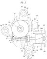
- the first wiper apparatus 12 has a motor apparatus 17 serving as a drive apparatus which drives the wiper arm 15.
- the motor apparatus 17 is provided with: a brushless motor 18; and a speed reduction mechanism 19 which transmits the power of the brushless motor 18 to the pivot shaft 14.
- the brushless motor 18 is formed as shown in FIGS. 2 to 4 .
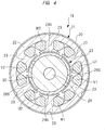
- the brushless motor 18 in this embodiment has a motor case 20 formed into a bottomed cylindrical shape, and an armature 21 serving as a stator is provided on an inner periphery of the motor case 20.
- the armature 21 has a stator core 22 and armature coils V1, V2, U1, U2, W1, and W2 wound around the stator core 22.
- the stator core 22 is stacked electrically-conductive metal plates, and, on the inner periphery of the stator core 22, a plurality of, specifically, six teeth 23 are provided at intervals in the circumferential direction.
- the armature coils V1, V2, U1, U2, W1, and W2 are separately wound around the six teeth 23, respectively.
- the armature coils V1 and V2 correspond to V-phases
- the armature coils U1 and U2 correspond to U-phases
- the armature coils W1 and W2 correspond to W-phases.
- clockwise with respect to the armature 21 the armature coil U1, the armature coil V1, the armature coil W1, the armature coil U2, the armature coil V2, and the armature coil W2 are provided in this order.
- the armature coils V1 and V2, the armature coils U1 and U2, and the armature coils W1 and W2 have mutually different phases of energization period.
- an end “Ua” of the armature coil U1 and an end “Ub” of the armature coil W2 are connected by a terminal 24.
- an end “Vb” of the armature coil U2 and an end “Va” of the armature coil V1 are connected by a terminal 25.
- an end “Wa” of the armature coil W1 and an end “Wb” of the armature coil V2 are connected by a terminal 26.
- the brushless motor 18 employs delta connections as the connection structure of the six armature coils.
- the brushless motor 18 has a rotor 27, and the rotor 27 is provided in the inner side of the armature 21.
- the brushless motor 18 has an inner-rotor-type structure in which the rotor 27 is disposed in the inner side of the armature 21, which is serving as a stator.
- the rotor 27 has a rotor shaft 28 and permanent magnets 29N and 29S of four polarities fixed to an outer periphery of the rotor shaft 28 via a rotor core 30.
- the polarity of the two permanent magnets 29N is the N pole
- the polarity of the two permanent magnets 29S is the S pole
- the permanent magnets 29N and the permanent magnets 29S are alternately disposed along the circumferential direction of the rotor shaft 28.
- the brushless motor 18 has 4 as the number of the permanent magnets, has 6 as the number of the armature coils, and has a four-pole six-slot structure.
- the brushless motor 18 has a SPM (Surface Permanent Magnet) structure.
- the SPM structure is a structure in which the permanent magnets 29N and 29S are fixed to the outer peripheral surface of the rotor core 30.
- the rotor core 30 is formed of an iron-based magnetic material.
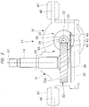
- the rotor shaft 28 is rotatably supported by a plurality of bearings 49.
- the motor apparatus 17 is provided with a gear case 31 which houses the speed reduction mechanism 19, and the gear case 31 and the motor case 20 are fixed by a fastener member (not shown).
- Part of the rotor shaft 28 in the length direction is disposed in the motor case 20, and the remaining part thereof is disposed in the gear case 31.
- a worm 32 is formed on the outer periphery of the part of the rotor shaft 28 that is disposed in the gear case 31.
- a worm wheel 33 is provided in the gear case 31.
- a gear 33a is formed on the outer periphery of the worm wheel 33, and the gear 33a and the worm 32 are meshed with each other.
- the pivot shaft 14 is disposed concentrically with the worm wheel 33, and the pivot shaft 14 is integrally rotated with the worm wheel 33.
- the worm 32 and the gear 33a are the speed reduction mechanism 19 in this embodiment.
- the speed reduction mechanism 19 is a mechanism which reduces the rotation number (output rotation number) of the pivot shaft 14 with respect to the rotation number (input rotation number) of the rotor 27 when the power of the rotor 27 is transmitted to the pivot shaft 14.
- the rotation number in this embodiment is the rotation number per unit time and synonymous with a rotation speed.
- a shaft hole (not shown) is provided in an upper part of the gear case 31 .
- the end of the pivot shaft 14 that is in the opposite side of the end to which the worm wheel 33 is fixed is exposed to outside via the shaft hole of the gear case 31.
- the wiper arm 15 is coupled to the part of the pivot shaft 14 that is exposed to outside the gear case 31.
- a sensor magnet 34 is attached to the part of the rotor shaft 28 that is disposed in the gear case 31.
- the sensor magnet 34 is integrally rotated with the rotor shaft 28.
- the sensor magnet 34 has a cylindrical shape, and the sensor magnet 34 is magnetized so that N poles and S poles are alternately juxtaposed along the circumferential direction of the rotor shaft 28.
- An opening is provided at a part of the gear case 31 that is in the opposite side of the shaft hole thereof. This opening is formed for inserting the worm wheel 33, the pivot shaft 14, etc. into the gear case 31.
- An under cover 35 which closes the opening, is provided.
- the under cover 35 has a tray shape, and a control board 36 is provided in the space surrounded by the under cover 35 and the gear case 31.
- a drive apparatus 37 which controls the brushless motor 18, is provided on the control board 36.
- the drive apparatus 37 has an inverter circuit 38, which controls energization to the six armature coils V1, V2, U1, U2, W1, and W2.
- the inverter circuit 38 is connected to the terminals 24, 25, and 26.
- the under cover 35 is provided with a connector 39; and, when an electric-power-source cable connected to an external electric power source 40 is connected to the connector 39, the external electric power source 40 and the inverter circuit 38 are connected to each other.
- the external electric power source 40 includes a battery, a capacitor, or the like mounted on the vehicle 10.
- the inverter circuit 38 is provided with a plurality of switching elements 38a, which separately connect or shut off the external electric power source 40 and the six armature coils V1, V2, U1, U2, W1, and W2.
- the switching elements 38a are composed of, for example, semiconductor elements such as FETs. More specifically, the switching elements include three positive-electrode-side switching elements corresponding to the U-phase, the V-phase, and the W-phase and connected to a positive electrode of the external electric power source 40 and include three negative-electrode-side switching elements corresponding to the U-phase, the V-phase, and the W-phase and connected to the negative-electrode side of the external electric power source 40.
- the number of the switching elements 38a provided is six in total.
- a control circuit (controller) 50 which switches on and off of the switching elements 38a, is connected to the inverter circuit 38.
- the control circuit 50 is a publicly-known microcomputer provided with a CPU, a RAM, a ROM, etc. Furthermore, the drive apparatus 37 has a PWM-signal generating circuit 51, and the signals of the PWM-signal generating circuit 51 are input to the control circuit 50.
- the control circuit 50 outputs drive signals which control the three negative-electrode-side switching elements, and the PWM signals are superimposed on the drive signals. Therefore, the three negative-electrode-side switching elements are driven by PWM control and are intermittently turned on in respective energization periods.
- the values of the currents supplied to the six armature coils V1, V2, U1, U2, W1, and W2 are controlled by controlling the rates at which the three negative-electrode-side switching elements are separately turned on, in other words, duty ratios.
- the energization periods in which electric power is supplied to the six armature coils V1, V2, U1, U2, W1, and W2 can be increased/reduced between 0% and 100% with respect to the entire period in which electric power can be distributed.
- the control circuit 50 stores data, programs, etc. for controlling the rotation number of the rotor 27 of the brushless motor 18.
- the brushless motor 18 in this embodiment can rotate the rotor 27 forward/backward by carrying out switching control of on and off of the switching elements 38a and inverting the directions of energization to the six armature coils V1, V2, U1, U2, W1, and W2. If the switching elements 38a are turned on, the external electric power source 40 and the armature coils V1, V2, U1, U2, W1, and W2 are separately connected; and, if the switching elements 38a are turned off, the external electric power source 40 and the armature coils V1, V2, U1, U2, W1, and W2 are separately shut off.
- the control board 36 is disposed along the planar direction which is perpendicular to a first axis A1 of the pivot shaft 14.
- the first axis A1 serves as a center when the pivot shaft 14 rotates.
- Three sensors 41, 42, and 43 are attached to the control board 36. All of the three sensors 41, 42, and 43 are Hall ICs, and the three sensors 41, 42, and 43 are fixed to the control board 36 without contacting the sensor magnet 34.
- the three sensors 41, 42, and 43 are arranged in the direction intersecting with a second axis B1 of the rotor shaft 28 as shown in FIG. 2 by a planar view of the control board 36.
- the second axis B1 serves as a center when the rotor shaft 28 rotates.
- the disposition range of the three sensors 41, 42, and 43 and the disposition range of the sensor magnet 34 are overlapped with each other at least partially in the direction along the second axis B1. Furthermore, if it is assumed that the control board 36 is horizontally disposed, as shown in FIG. 3 , the single sensor 42 is disposed immediately below the second axis B1. The three sensors 41, 42, and 43 are disposed at equal intervals in the direction intersecting with the second axis B1. Furthermore, the sensor 42 is disposed between the sensor 41 and the sensor 43.
- the control circuit 50 can detect the rotation angle and the rotation number of the rotor 27.
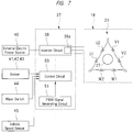
- a wiper switch 44 is provided in the interior of the vehicle 10. When a driver manipulates the wiper switch 44 and selects a low-speed mode or a high-speed mode, manipulation signals of the wiper switch 44 are input to the control circuit 50.
- a vehicle-speed sensor 45 which detects the travelling speed of the vehicle 10, is provided, and detection signals of the vehicle-speed sensor 45 are input to the control circuit 50.
- the control circuit 50 stores, in advance, data, arithmetic expressions, etc. that control the timing to turn on/off the switching elements 38a of the inverter circuit 38, the duration time to turn on the switching elements 38a, etc. on the basis of various conditions such as the manipulation signals of the wiper switch 44, the detection signals of the vehicle-speed sensor 45, and the actuation load of the wiper arm 15.
- the actuation load of the wiper arm 15 can be specifically estimated from the signals of the sensors 41, 42, and 43.
- a target rotation number of the rotor 27 to achieve a target wiping speed of the wiper arm 15 is obtained, and energization control is carried out so that the actual rotation number of the rotor 27 becomes the target rotation number.
- the action resistance of the wiper arm 15, in other words, the actuation load of the wiper arm 15 is increased by snow or the like.
- the actuation load of the wiper arm 15 is different.
- the inclination angle of the windshield 11 is expressed by the acute-angle-side inclination angle of the windshield 11 with respect to the horizontal plane.
- the actuation load of the wiper arm 15 is varied depending on the length of the wiper blade 16.
- the gear case 31 is provided with attachment parts 46, for example, three attachment parts, and the attachment parts 46 are provided with shaft holes, respectively. Furthermore, buffer materials 47 are attached to the shaft holes of the attachment parts 46, respectively.
- the buffer materials 47 are annularly formed synthetic rubbers, and screw members are inserted to holes 47a of the buffer materials 47 to attach the motor apparatus 17 to a vehicle body 48.
- the control circuit 50 estimates the rotation position of the rotor 27, in other words, the angle thereof in a rotation direction and carries out energization control on the basis of the rotation position of the rotor 27.
- the positive-electrode-side switching elements of the phases are sequentially turned on respectively by predetermined angles in electric angles, in other words, energization angles
- the negative-electrode-side switching elements of the phases which are different from the positive-electrode-side switching elements, are sequentially turned on by predetermined energization angles, thereby switching the energization state with respect to the armature coils U1, U2, V1, V2, W1, and W2 and commutating phase currents.
- a rotating magnetic field is formed by the armature 21, and the rotor 27 is rotated.
- the brushless motor 18 can subject the rotor 27 to forward rotations, stop, and backward rotations by subjecting the on and off of the switching elements 38a to switching control and inverting the directions of electric distribution to the armature coils U1, U2, V1, V2, W1, and W2. If the power of the rotor 27 is transmitted to the pivot shaft 14 via the speed reduction mechanism 19, the wiper arm 15 reciprocates within the range of a predetermined angle, and the windshield 11 is wiped off by the wiper blade 16.
- the brushless motor 18 has a characteristic that the rotation number of the rotor 27 is increased as the current value is increased. Furthermore, the brushless motor 18 has a characteristic that the torque of the rotor 27 is reduced as the rotation number of the rotor 27 is increased.
- the brushless motor 18 of this embodiment when the brushless motor 18 of this embodiment is to control the output, in other words, the rotation number and torque of the rotor 27, the brushless motor 18 can switch and execute first energization control, weak field control, and second energization control.
- the first energization control, the weak field control, and the second energization control are switched by various conditions such as the detection signals of the wiper switch 44, the detection signals of the vehicle-speed sensor 45, and the load of the wiper arm 15.
- the weak field control is executed when there is a request to increase the rotation number of the rotor 27 compared with the first energization control.
- the second energization control is executed when there is a request to increase the torque of the rotor 27 compared with the first energization control.
- the first energization control, the weak field control, and the second energization control will be described by FIG. 8 .
- the angles 0° to 360° shown in FIG. 8 are the energization angles expressing the energization periods in one cycle of electric signals.
- the positive expresses that electric power is distributed from the positive electrode to the armature coils V1, V2, U1, U2, W1, and W2, and the negative expresses that electric power is distributed from the negative electrode to the armature coils V1, V2, U1, U2, W1, and W2.
- the energization control shown in FIG. 8 exemplifies the state of energization to a predetermined single armature coil.
- FIG. 8A shows the first energization control.
- the first energization control uses an energization angle 0° as a reference, starts energization from the positive electrode to the predetermined armature coil at the position of an energization angle 30°, maintains the energization in the range of an energization angle 120°, and then terminates the energization from the positive electrode.
- the first energization control has an interval in the range of an energization angle 60° after the energization from the positive electrode is terminated, starts energization from the negative electrode to the predetermined armature coil, maintains the energization in the range of an energization angle 120°, and then terminates the energization.
- FIG. 8B shows the weak field control.
- an energization angle 0° serves as a reference, energization from the positive electrode is started at the position of an energization angle 15°, the energization from the positive electrode is maintained in the range of an energization angle 120°, and, then, the energization from the positive electrode is terminated.
- the position of the energization angle 15° at which the energization from the positive electrode is started in FIG. 8B is the timing earlier than the position of the energization angle 30° shown in FIG. 8A .
- the position of the energization angle 15° has undergone angle advancement by the amount corresponding to the energization angle 15°.
- an energization angle 0° serves as a reference
- energization from the positive electrode is started at the position of an energization angle 15°
- the energization from the positive electrode is maintained in the range of an energization angle 120°+ ⁇
- the energization from the positive electrode is terminated at the position of an energization angle 165°.
- energization from the positive electrode is terminated, energization from the negative electrode is started at an energization angle 195°, the energization from the negative electrode is maintained in the range of an energization angle 120°+ ⁇ , and, then, the energization from the negative electrode is terminated.
- the energization timing in the second energization control is earlier than the energization starting timing of the first energization control by the range of the energization angle 15°, and the range of the energization angle 120°+ ⁇ , in which the energization is continued in the second energization control, is wider than the range of the energization angle 120° in which the energization is continued in the first energization control.
- the range of the energization angle 120° is a first period of the present invention
- the range of the energization angle 120°+ ⁇ is a second period of the present invention.
- the first energization control is executed, for example, when the low-speed mode is selected.
- the first energization control causes the actual rotation number of the rotor 27 to be closer to the required target rotation number by controlling the duty ration without carrying out the weak field control.
- the timing to start energization to the armature coils U1, U2, V1, V2, W1, and W2 is at the position of a fixed value determined in advance, in other words, the energization angle 30°.
- the weak field control or the second energization control is executed, for example, when the high-speed mode is selected.
- the weak field control is executed without changing the current values supplied to the armature coils U1, U2, V1, V2, W1, and W2.
- the weak field control is the control in which the magnetic field formed by the armature 21 is weakened as much as possible by supplying currents to the armature coils U1, U2, V1, V2, W1, and W2.
- this weak field control is carried out, the back electromotive force generated at the armature coils U1, U2, V1, V2, W1, and W2 is reduced, and the rotation number of the rotor 27 is increased.
- the second energization control is to cause the energization period to be longer than that of the first energization control and the second energization control in addition to the weak field control.
- FIG. 9 is a diagram showing characteristics of the brushless motor 18.
- the rotation number of the brushless motor 18 is shown by a vertical axis
- the torque of the brushless motor 18 is shown by a horizontal axis.
- FIG. 9 shows an example of the characteristics for the low-speed mode and an example of high-speed mode characteristics.
- a single characteristic is present at the position shown by a solid line so that the rotation number and torque corresponding to the low-speed mode characteristic of FIG. 9 can be obtained when the rating thereof is set. Therefore, if the low-speed mode is selected, the required rotation number and torque can be obtained in the range equal to and blow the single characteristic by executing the first energization control.
- the single characteristic is the target output of the case in which the actual vehicle speed of the vehicle 10 is equal to or less than a reference vehicle speed, in other words, is the characteristic that satisfies the low-speed mode.
- An apparent characteristic is the target output of the case in which the actual vehicle speed of the vehicle 10 exceeds the reference vehicle speed, in other words, is the characteristic that satisfies the high-speed mode.
- the target output can be expressed by the rotation number and torque of the rotor 27.
- the conditions that determine the target output include various conditions such as the detection signals of the wiper switch 44, the detection signals of the vehicle-speed sensor 45, and the load of the wiper arm 15.
- the rotation number and torque exceeding the single characteristic can be obtained by executing the weak field control or the second energization control by the control circuit 50.
- the characteristic of the brushless motor 18 is equivalent to the presence at the positions shown by a dashed-dotted line in FIG. 9 in terms of appearance.
- the brushless motor 18 can be subjected to determination of the rating thereof while using the low-speed mode as a reference in terms of design, and the size of the brushless motor 18 can be reduced as much as possible.
- the fact that the rotation number of the brushless motor 18 can be increased and the torque can be increased without changing the current value means that a torque constant is relatively increased.
- the brushless motor 18 of this embodiment can generate high torque as much as possible with smaller electric power consumption, and motor efficiency is improved.
- the characteristics of the brushless motor 18 of the case in which the weak field control or the second energization control is carried out will be described on the basis of the characteristic diagrams of FIGS. 10A and 10B .
- torque is shown by horizontal axes
- rotation numbers are shown by vertical axes.
- the characteristic diagram of FIG. 10A shows the characteristics of the brushless motor 18 in the case in which the second energization control is executed.
- a solid line represents the characteristic of an advance angle 30°
- a broken line represents the characteristic of an advance angle 45°
- a dashed-dotted line represents the characteristic of an advance angle 60°.
- advance angle 30°, advance angle 45°, and advance angle 60° mean that the energization to the armature coil is started at the timing earlier by the advance angle 30°, the advance angle 45°, and the advance angle 60° than the position of the energization angle 30°, which is the timing at which the energization to the armature coil is started in the first energization control.
- the period of the energization to the armature coil is continued across the range of the energization angle 120° regardless of the advance angle.
- FIG. 10A it can be understood that the rotation number of the rotor is relatively increased as the advance angle is increased even if the torque of the rotor is the same. Furthermore, in the three characteristics, the rotation number is reduced as the torque of the rotor is increased. Furthermore, as the torque of the rotor is increased, the differences in the rotation numbers of the rotor in the three characteristics are reduced.
- a solid line represents the characteristic of an energization angle 120° with an advance angle 30°
- a broken line represents the characteristic of an energization angle 135° with an advance angle 37.5°
- a dashed-dotted line represents the characteristic of an energization angle 150° with an advance angle 45°
- a dashed two-dotted line represents the characteristic of an energization angle 165° with an advance angle 52.5°.
- the basic characteristics of the brushless motor 18 shown in FIG. 10B are the same as the basic characteristics of the brushless motor 18 shown in FIG. 10A .
- the differences in the rotation numbers in the high-torque region are larger in the characteristics of the brushless motor 18 shown in FIG. 10B than the characteristics of the brushless motor 18 shown in FIG. 10A .
- FIG. 11 is a graph chart showing the relation between the advance angles, the energization angles, and torque ripple rates.
- the horizontal axis shows the energization angles.
- Torque ripples mean changes, in other words, pulsations of the torque of the rotor.
- the torque ripple rate is the ratio of the pulsation width of the torque with respect to the average of the torque.
- the torque ripple rates of the rotor with respect to an advance angle 0°, an advance angle 15°, and an advance angle 30°, respectively, are shown.
- the advance angle 0° corresponds to first timing of the present invention
- the advance angle 15° and the advance angle 30° correspond to second timing of the present invention.
- the advance angle 15° means advancing the timing to start energization by the amount corresponding to the energization angle 15° with respect to the advance angle 0°
- the advance angle 30° means to advance the timing to start energization by the amount corresponding to the energization angle 30° with respect to the advance angle 0°.
- the torque ripple rate in the case in which the second energization control is executed can be reduced more than the torque ripple rate in the case in which the first energization control is executed.
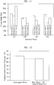
- FIG. 12 shows an example of comparing the radiated sound (sound pressures) generated around the brushless motor in the case in which control is carried out by using rectangular waves as current waveforms and the case in which control is carried out by the waveforms smoother than the rectangular waves when control of the energization to the armature coil of the brushless motor 18 is executed.
- the current waveform becomes a rectangular wave.
- the second energization control is executed, the current waveform becomes a smooth waveform. According to FIG. 12 , it can be understood that the sound pressure in the case in which the second energization control is executed is lower than the sound pressure of the case in which the first energization control is executed.
- FIG. 13 shows the waveforms showing the relations between currents and electric signals in the case in which the energization to the armature coil of the brushless motor 18 is executed.
- the waveform of the advance angle 60° and the energization angle 165° is shown by a solid line
- the waveform of the advance angle 0° and the energization angle 120° is shown by a dashed two-dotted line
- the waveform of the advance angle 30° and the energization angle 150° is shown by a broken line
- the waveform of the advance angle 15° and the energization angle 120° is shown by a dashed-dotted line.
- the waveform of the advance angle 60° and the energization angle 165° has a most smoothly changed current and approximates a sine wave. More specifically, the waveform of the advance angle 60° and the energization angle 165° has the lowest radiated sound (sound pressure) generated around the brushless motor compared with the other waveforms and can reduce the actuation sound of the brushless motor 18.
- FIG. 14 is a graph chart showing the relations between the advance angles, the energization angles, and sound pressures.
- FIG. 14 shows the sound pressures at the energization angle 120° with the advance angle 0°, the advance angle 15°, and the advance angle 30°, shows the sound pressures at the energization angle 150° with the advance angle 15° and the advance angle 30°, and shows the sound pressures at the energization angle 165° with the advance angle 60°.
- the sound pressure at the advance angle 15° and the energization angle 150° and the sound pressure at the advance angle 60° and the energization angle 165° are lower than the sound pressures at the other advance angles and energization angles.
- the advance angle 0° is the first timing
- the advance angle 15° and the advance angle 30° are the second timing
- the advance angle 60° may be the second timing at which the timing to start energization is advanced by the amount corresponding to the energization angle 60° with respect to the advance angle 0°, which is the first timing.
- the advance angle and the energization angle can be controlled in accordance with various conditions such as the selected mode, the vehicle speed, and the load of the wiper arm 15 so that the torque ripple rate becomes small. Furthermore, when the energization to the armature coil of the brushless motor 18 is controlled, the advance angle and the energization angle can be controlled in accordance with the various conditions so that the sound pressure becomes low.
- the rigidity, the attachment position, etc. of the vehicle body 48 to which the motor apparatus 17 is attached is different in every vehicle model, and the resonant frequency in the case in which the brushless motor 18 is actuated is different in every vehicle model. Therefore, the advance angle and the energization angle can be tuned for every vehicle model so that the sound pressure generated around the brushless motor 18 becomes low.
- the drive apparatus of the present invention is not limited to that of the above described first embodiment, and it goes without saying that various modifications can be made within the range not deviating from the gist thereof.
- the brushless motor of the present invention includes the structure of a star connection in which armature coils are connected in Y shapes.
- the brushless motor of the present invention includes one in which the rotor has an IPM (Interior Permanent Magnet) structure. In the IPM structure, permanent magnets are buried in the rotor core.
- the first period is not limited to the energization angle 120°, but may be less than the energization angle 120°, or may exceed the energization angle 120°.
- the brushless motor of the present invention includes the inner-rotor-type structure in which the rotor is disposed in the inner side of the stator and an outer-rotor-type structure in which the rotor is disposed in the outer side of the stator.
- the wiper apparatus of the present invention includes a wiper apparatus in which the wiper blade wipes off a rear glass.
- the wind glass of the wiper apparatus of the present invention includes a windshield and a rear glass.
- the wiper apparatus of the present invention includes a configuration in which two wiper arms are singularly driven by a single brushless motor.
- the brushless motor of the first embodiment includes, other than the wiper motor that operates the wiper apparatus, brushless motors provided for operating action members such as a door, a roof, a glass, etc. in, for example, a power slide door apparatus, a sunroof apparatus, or a power window apparatus provided in a vehicle.
- the drive apparatus 37 corresponds to a control unit and a mode switching unit of the present invention.
- the second embodiment is one example of a motor apparatus applied to the vehicle.
- FIGS. 2-5 and 9 used in the first embodiment will be used also in the second embodiment.
- a vehicle 10 shown in FIG. 15 has a windshield 11. Furthermore, the vehicle 10 has a first wiper apparatus 12 and a second wiper apparatus 13, which wipe off the windshield 11. The first wiper apparatus 12 and the second wiper apparatus 13 are disposed at the positions which are different from each other in the width direction of the vehicle 10. Since the first wiper apparatus 12 and the second wiper apparatus 13 have approximately left-right symmetric structures, the first wiper apparatus 12 will be described hereinafter for the sake of convenience.
- the first wiper apparatus 12 has: a wiper arm 15 which swings about a pivot shaft 14; and a wiper blade 16 which is attached to the wiper arm 15. Furthermore, the first wiper apparatus 12 has a motor apparatus 17 which drives the wiper arm 15.
- the motor apparatus 17 is provided with: a brushless motor 18; and a speed reduction mechanism 19 which transmits the power of the brushless motor 18 to the pivot shaft 14.
- the brushless motor 18 is formed as shown in FIGS. 2 to 4 .
- the brushless motor 18 in this embodiment has a motor case 20 formed into a bottomed cylindrical shape, and an armature 21 serving as a stator is provided on an inner periphery of the motor case 20.
- the armature 21 has a stator core 22 and armature coils V1, V2, U1, U2, W1, and W2 wound around the stator core 22.
- the stator core 22 is stacked electrically-conductive metal plates, and, on the inner periphery of the stator core 22, a plurality of, specifically, six teeth 23 are provided at intervals in the circumferential direction and disposed at a mechanical angle of 60°.
- the armature coils V1, V2, U1, U2, W1, and W2 are separately wound around the six teeth 23, respectively.
- the armature coils V1 and V2 correspond to V-phases
- the armature coils U1 and U2 correspond to U-phases
- the armature coils W1 and W2 correspond to W-phases.
- clockwise with respect to the armature 21 the armature coil U1, the armature coil V1, the armature coil W1, the armature coil U2, the armature coil V2, and the armature coil W2 are provided in this order.
- the armature coils U1 and U2 are in positional relationship of mechanical angle 180° with each other, the armature coils V1 and V2 are in positional relationship of mechanical angle 180° with each other, and the armature coils U1 and U2 are in positional relationship of mechanical angle 180° with each other.
- the armature coils U1 and U2 are connected in series, the armature coils V1 and V2 are connected in series, and the armature coils W1 and W2 are connected in series, Furthermore, an end “Ua” of the armature coil U1 and an end “Ub” of the armature coil W2 are connected by a terminal 24. Also, an end “Vb” of the armature coil U2 and an end “Va” of the armature coil V1 are connected by a terminal 25. Furthermore, an end “Wa” of the armature coil W1 and an end “Wb” of the armature coil V2 are connected by a terminal 26. In this manner, the brushless motor 18 employs delta connections as the connection structure of the six armature coils V1, V2, U1, U2, W1, and W2.
- the brushless motor 18 has a rotor 27, and the rotor 27 is provided in the inner side of the armature 21.
- the brushless motor 18 has an inner-rotor-type structure in which the rotor 27 is disposed in the inner side of the armature 21, which is serving as a stator.
- the rotor 27 has a rotor shaft 28 and permanent magnets 29N and 29S of four polarities fixed to an outer periphery of the rotor shaft 28 via a rotor core 30.
- the polarity of the two permanent magnets 29N is the N pole
- the polarity of the two permanent magnets 29S is the S pole
- the permanent magnets 29N and the permanent magnets 29S are alternately disposed along the circumferential direction of the rotor shaft 28.
- the brushless motor 18 has four permanent magnets, six armature coils, and a four-pole six-slot structure.
- the brushless motor 18 has a SPM (Surface Permanent Magnet) structure.
- the SPM structure is a structure in which the permanent magnets 29N and 29S are fixed to the outer peripheral surface of the rotor core 30.
- the rotor core 30 is formed of an iron-based magnetic material.
- the rotor shaft 28 is rotatably supported by a plurality of, specifically, two bearings 49.
- the motor apparatus 17 is provided with a gear case 31, which houses the speed reduction mechanism 19, and the gear case 31 and the motor case 20 are fixed by a fastener member (not shown).
- a gear case 31 which houses the speed reduction mechanism 19, and the gear case 31 and the motor case 20 are fixed by a fastener member (not shown).
- Part of the rotor shaft 28 in the length direction is disposed in the motor case 20, and the remaining part thereof is disposed in the gear case 31.
- a worm 32 is formed on the outer periphery of the part of the rotor shaft 28 that is disposed in the gear case 31.
- a worm wheel 33 is provided in the gear case 31.
- a gear 33a is formed on the outer periphery of the worm wheel 33, and the gear 33a and the worm 32 are meshed with each other.
- the pivot shaft 14 is disposed concentrically with the worm wheel 33, and the pivot shaft 14 is integrally rotated with the worm wheel 33.
- the worm 32 and the gear 33a are the speed reduction mechanism 19 in this embodiment.
- the speed reduction mechanism 19 is a mechanism which reduces the rotation number (output rotation number) of the pivot shaft 14 with respect to the rotation number (input rotation number) of the rotor 27 when the power of the rotor 27 is transmitted to the pivot shaft 14.
- the rotation number in this embodiment is the rotation number per unit time and is synonymous with a rotation speed.
- a shaft hole (not shown) is provided in an upper part of the gear case 31 .
- the end of the pivot shaft 14 that is in the opposite side of the end to which the worm wheel 33 is fixed is exposed to outside via the shaft hole of the gear case 31.
- the wiper arm 15 is coupled to the part of the pivot shaft 14 that is exposed to outside the gear case 31.
- a sensor magnet 34 is attached to the part of the rotor shaft 28 that is disposed in the gear case 31.
- the sensor magnet 34 is integrally rotated with the rotor shaft 28.
- the sensor magnet 34 has a cylindrical shape, and the sensor magnet 34 is magnetized so that N poles and S poles are alternately juxtaposed along the circumferential direction of the rotor shaft 28.
- An opening is provided at a part of the gear case 31 that is in the opposite side of the shaft hole thereof. This opening is formed for inserting the worm wheel 33, the pivot shaft 14, etc. into the gear case 31.
- An under cover 35 which closes the opening, is provided.
- the under cover 35 has a tray shape, and a control board 36 is provided in the space surrounded by the under cover 35 and the gear case 31.
- a drive apparatus 37 which controls the brushless motor 18, is provided on the control board 36.
- the drive apparatus 37 has an inverter circuit 38, which controls energization to the six armature coils V1, V2, U1, U2, W1, and W2.
- the inverter circuit 38 is connected to the terminals 24, 25, and 26.
- the under cover 35 is provided with a connector 39; and, when an electric-power-source cable connected to an external electric power source 40 is connected to the connector 39, the external electric power source 40 and the inverter circuit 38 are connected to each other.
- the external electric power source 40 includes a battery, a capacitor, or the like mounted on the vehicle 10.
- the inverter circuit 38 is provided with a plurality of, specifically, six switching elements 38a to 38f which separately connect or shut off supply paths between the external electric power source 40 and the six armature coils V1, V2, U1, U2, W1, and W2.
- the six switching elements 38a to 38f are composed of, for example, semiconductor elements such as FETs. More specifically, the positive-electrode-side switching element 38b corresponding to the U-phase and connected to the positive electrode of the external electric power source 40 and the negative-electrode-side switching element 38e corresponding to the U-phase and connected to the negative electrode side of the external electric power source 40 are provided.
- the positive-electrode-side switching element 38b corresponding to the V-phase and connected to the positive electrode of the external electric power source 40 and the negative-electrode-side switching element 38e corresponding to the V-phase and connected to the negative electrode side of the external electric power source 40 are provided. Furthermore, the positive-electrode-side switching element 38c corresponding to the W-phase and connected to the positive electrode of the external electric power source 40 and the negative-electrode-side switching element 38f corresponding to the W-phase and connected to the negative electrode side of the external electric power source 40 are provided.
- the switching elements 38a, 38b, and 38c are connected in mutually parallel, and the switching elements 38d, 38e, and 38f are connected in mutually parallel. Furthermore, the switching element 38a and the switching element 38d are connected in series, the switching element 38b and the switching element 38e are connected in series, and the switching element 38c and the switching element 38f are connected in series. Furthermore, a source of the switching element 38a and a drain of the switching element 38d are connected to the terminal 24. Furthermore, a source of the switching element 38b and a drain of the switching element 38e are connected to the terminal 25. Furthermore, a source of the switching element 38c and a drain of a switching element 38f are connected to the terminal 26.
- the drive apparatus 37 is provided with a control circuit 50 for controlling the six switching elements 38a to 38f.
- the control circuit 50 is a publicly-known microcomputer provided with a CPU, a RAM, a ROM, etc.
- the drive apparatus 37 has a PWM-signal generating circuit 51, and the signals of the PWM-signal generating circuit 51 are input to the control circuit 50.
- the control circuit 50 outputs drive signals which separately control the six switching elements 38a to 38f, and the PWM signals are superimposed on the drive signals. Therefore, the switching elements 38a to 38f are driven by PWM control and are intermittently turned on/off in respective energization periods.
- the values of the currents supplied to the six armature coils V1, V2, U1, U2, W1, and W2 are controlled by controlling ratios at which the switching elements 38a to 38f are separately turned on, in other words, "duty ratios".
- the energization periods in which electric power is supplied to the six armature coils V1, V2, U1, U2, W1, and W2 can be increased/reduced between 0% and 100% with respect to the entire period in which electric power can be distributed.
- waves of currents to be respectively supplied to the armature coils V1, V2, U1, U2, W1, and W2 are represented by electric angles, the "energization periods" have important implications.
- the brushless motor 18 of this embodiment can rotate the rotor 27 forward/backward by subjecting the on and off of the switching element 38a to switching control and inverting the directions of energization to the six armature coils V1, V2, U1, U2, W1, and W2.
- the control board 36 is disposed along the planar direction which is perpendicular to a first axis A1 of the pivot shaft 14.
- the first axis A1 serves as a center when the pivot shaft 14 rotates.
- Three sensors 41, 42, and 43 are attached to the control board 36. All of the three sensors 41, 42, and 43 are Hall ICs, and the three sensors 41, 42, and 43 are fixed to the control board 36 without contacting the sensor magnet 34.
- the sensor 41 outputs a switching signal corresponding to the W-phase
- the sensor 42 outputs a switching signal corresponding to the V-phase
- the sensor 43 outputs a switching signal corresponding to the U-phase.
- the three sensors 41, 42, and 43 are arranged in the direction intersecting with a second axis B1 of the rotor shaft 28 as shown in FIG. 2 by a planar view of the control board 36.
- the second axis B1 serves as a center when the rotor shaft 28 rotates.
- the disposition range of the three sensors 41, 42, and 43 and the disposition range of the sensor magnet 34 are overlapped with each other at least partially in the direction along the second axis B1. Furthermore, if it is assumed that the control board 36 is horizontally disposed, as shown in FIG. 3 , the single sensor 42 corresponding to V-phase is disposed immediately below the second axis B1. The three sensors 41, 42, and 43 are disposed at equal intervals in the direction intersecting with the second axis B1. Furthermore, the sensor 42 is disposed between the sensor 41 and the sensor 43.
- the control circuit 50 can detect the rotation phase and the rotation number of the rotor 27.
- the rotation phase of the rotor 27 is an angle or a position in a rotation direction defined with respect to a reference position.
- the control circuit 50 further has a function to estimate an actuation load on the basis of the switching signals of the three sensors 41, 42, and 43.
- a wiper switch 44 is provided in the interior of the vehicle 10. When a driver manipulates the wiper switch 44 and selects a low-speed mode or a high-speed mode, manipulation signals of the wiper switch 44 are input to the control circuit 50. Furthermore, a vehicle-speed sensor 45, which detects the travelling speed of the vehicle 10, is provided, and detection signals of the vehicle-speed sensor 45 are input to the control circuit 50.
- control circuit 50 stores, in advance, data of outputs from the rotor 27 of the brushless motor 18, that is, data of energization pattern and the like of the six armature coils V1, V2, U1, U2, W1, and W2, in order to control the rotation number and the torque. More specifically, the control circuit 50 stores, in advance, data, arithmetic expressions, etc. that control the timing to turn on/off the switching elements 38a of the inverter circuit 38, the duration time to turn on the switching elements 38a to 38f on the basis of various conditions such as the manipulation signals of the wiper switch 44, the detection signals of the vehicle-speed sensor 45, and the actuation load of the wiper arm 15.
- the actuation load of the wiper arm 15 can be specifically estimated from the switching signals of the sensors 41, 42, and 43.
- the control circuit 50 for example, it is assumed that the high-speed mode is selected, a target rotation number of the rotor 27 to achieve a target wiping speed of the wiper arm 15 is obtained, and energization control is carried out so that the actual rotation number of the rotor 27 becomes the target rotation number.
- the control circuit 50 if the actual rotation number of the rotor 27 does not become the target rotation number, it can be estimated that the action resistance of the wiper arm 15, in other words, the actuation load of the wiper arm 15 is increased by snow or the like.
- the actuation load of the wiper arm 15 is changed depending on the vehicle speed. Furthermore, the wind pressure received by the wiper arm 15 is changed depending on the inclination angle of the windshield 11, and, therefore, the actuation load of the wiper arm 15 is changed depending on the inclination angle of the windshield 11.
- the inclination angle of the windshield 11 is expressed by the acute-angle-side inclination angle of the windshield 11 with respect to the horizontal plane. Furthermore, the actuation load of the wiper arm 15 is changed depending on the length of the wiper blade 16.
- the gear case 31 is provided with attachment parts 46 at plural, for example, three locations, and the attachment parts 46 are provided with shaft holes, respectively. Furthermore, buffer materials 47 are attached to the shaft holes of the attachment parts 46, respectively.
- the buffer materials 47 are annularly formed synthetic rubbers, and screw members are inserted to holes 47a of the buffer materials 47 to attach the motor apparatus 17 to a vehicle body 48.
- the control circuit 50 of the motor apparatus 17 the on/off of the switching elements 38a are controlled by the manipulation signals of the wiper switch 44 or a condition other than the manipulation signals of the wiper switch 44. Furthermore, on the basis of the detection signals of the three sensors 41, 42, and 43, the control circuit 50 estimates the rotation phase of the rotor 27, in other words, the angle thereof in a rotation direction and carries out energization control on the basis of the rotation phase of the rotor 27.
- the positive-electrode-side switching elements 38a 38b, and 38c are sequentially turned on/off respectively by predetermined electric angles, in other words, energization angles
- the negative-electrode-side switching elements 38d, 38e, and 38f are sequentially turned on/off by predetermined electric angles, thereby switching the energization state with respect to the armature coils U1, U2, V1, V2, W1, and W2 and commutating phase currents.
- a rotating magnetic field is formed by the armature 21, and the rotor 27 is rotated.
- the brushless motor 18 can subject the rotor 27 to forward rotations, stop, and backward rotations by subjecting the on and off of the switching elements 38a to 38f to switching control and inverting the directions of electric distribution to the armature coils U1, U2, V1, V2, W1, and W2. If the power of the rotor 27 is transmitted to the pivot shaft 14 via the speed reduction mechanism 19, the wiper arm 15 reciprocates within the range of a predetermined angle, and the windshield 11 is wiped off by the wiper blade 16.
- the wiper arm 15 reciprocates, for example, between a lower inverting position D1 shown by a solid line and an upper inverting position D2 shown by a dashed two-dotted line.
- the upper inverting position D2 is at a position which is more distant than the lower inverting position D1 is from the vehicle body 48 to which the motor apparatus 17 is attached.
- the location at which the motor apparatus 17 is attached is, for example, a lower side of a louver.
- the range in which the wiper arm 15 is moved from the lower inverting position toward the upper inverting position D2 is a forward path
- the range in which the wiper arm 15 is moved from the upper inverting position D2 toward the lower inverting position D1 is a return path. Note that it is assumed that, if the wiper arm 15 is moved in the forward path, the rotor 27 shown in FIG. 3 is rotated, for example, counterclockwise; and, if the wiper arm 15 is moved in the return path, the rotor 27 is rotated clockwise.
- the control circuit 50 can control output of the rotor 27 by controlling the timing of the electric angles to turn on or off the switching elements 38a to 38f, the sections of the electric angles to turn on the switching elements 38a to 38f, etc.
- the timing of the electric angles can be also referred to as the points of the electric angles.
- the brushless motor 18 has a characteristic that the rotation number of the rotor 27 is increased as the current value is increased. Furthermore, the brushless motor 18 has a characteristic that the torque of the rotor 27 is reduced as the rotation number of the rotor 27 is increased.
- the brushless motor 18 of this embodiment controls the output, in other words, the rotation number and torque of the rotor 27, the brushless motor 18 can switch and execute first energization control, weak field control, and third energization control.
- the first energization control, the weak field control, and the third energization control are switched by various conditions such as the detection signals of the wiper switch 44, the detection signals of the vehicle-speed sensor 45, the load of the wiper arm 15, and the moving direction of the wiper arm 15.
- the weak field control can be executed when there is a request to increase the rotation number of the rotor 27 compared with the first energization control.
- the third energization control can be executed when there is a request to increase the torque of the rotor 27 compared with the first energization control. That is, the third energization control is executed when the actuation load of the wiper arm 15 is increased by snow and the like deposited on the front windshield 11.
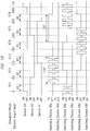
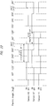
- FIG. 17 shows the drive patterns of the switching elements 38a to 38f in the case in which the wiper arm 15 is moved in the forward path
- FIG. 18 shows the drive patterns of the switching elements 38a to 38f in the case in which the wiper arm 15 is moved in the return path.
- the drive patterns of FIGS. 17 and 18 are divided into six energization stages ST1 to ST6, which are started from rising edges or falling edges of the switching signals output from the sensors 41, 42, and 43, and, in this case, the energization stages are divided by the electric angles (degrees) determined in advance. In the examples of FIGS. 17 and 18 , the energization stages are divided by the ranges (sections) of the electric angle 60°.
- the rising of the switching signal means switching of the switching signal from "off' to "on", and the falling of the switching signal means switching of the switching signal from "on" to "off'.
- the on-section of each of the switching signals of the sensors 41, 42, and 43 is set to an electric angle 180°, and the on-sections of the switching signals of the sensors 41, 42, and 43 are set so as to be mutually shifted by the electric angle 60°.
- FIG. 17 shows the drive patterns corresponding to the forward path of the wiper arm 15, wherein the switching signal of the sensor 43 corresponding to the U-phase is turned on at the timing of an electric angle 0° and is turned off at the timing of the electric angle 180°. While the switching signal of the sensor 43 corresponding to the U-phase is turned on, the switching signal of the sensor 41 corresponding to the W-phase is turned on at the timing of the electric angle 60°. The switching signal of the sensor 43 corresponding to the U-phase is turned off at the timing of an electric angle 240°.
- the switching signal of the sensor 41 corresponding to the W-phase is turned on
- the switching signal of the sensor 42 corresponding to the V-phase is turned on at the timing of the electric angle 120°.
- the switching signal of the sensor 42 corresponding to the V-phase is turned off at the timing of an electric angle 300°.
- the control circuit 50 controls the switching elements 38a to 38f in a below manner on the basis of the switching signals of the sensors 41, 42, and 43.
- the positive-electrode-side switching element 38a of the U-phase is constantly turned on in the section of an electric angle 120° from the timing of an electric angle 30° to the timing of an electric angle 150° and is alternately switched to "on” and “off' in the section of an electric angle 120° from the timing of an electric angle 210° to the timing of an electric angle 330°. Meanwhile, the negative-electrode-side switching element 38d of the U-phase is alternately switched to "on” and "off' in the section of an electric angle 120° from the timing of the electric angle 210° to the timing of the electric angle 330°.
- the positive-electrode-side switching element 38b of the V-phase is alternately switched to "on” and “off' in the section of an electric angle 120° from the timing of the electric angle 330° to the timing of an electric angle 90°. Furthermore, the positive-electrode-side switching element 38b of the V-phase is turned on at the timing of the electric angle 150° and is constantly turned on until it is turned off at the timing of an electric angle 270°. On the other hand, the negative-electrode-side switching element 38e of the V-phase is alternately switched to "on” and "off' in the section of an electric angle 120° from the timing of the electric angle 330° to the timing of the electric angle 90°.
- the positive-electrode-side switching element 38c of the W-phase is constantly turned on in the section of an electric angle 120° from the timing of the electric angle 270° to the timing of the electric angle 30°, and positive-electrode-side switching element 38c of the W-phase is alternately switched to "on” and “off' in the section of an electric angle 120° from the timing of the electric angle 90° to the timing of the electric angle 210°. Furthermore, the negative-electrode-side switching element 38c of the W-phase is alternately switched to "on” and "off' in the section of an electric angle 120° from the timing of the electric angle 90° to the timing of the electric angle 210°.
- FIG. 18 shows the drive patterns corresponding to the return path, wherein the switching signal of the sensor 43 corresponding to the U-phase is turned on at the timing of the electric angle 0° and is turned off at the timing of the electric angle 180°. While the switching signal of the sensor 43 corresponding to the U-phase is turned on, the switching signal of the sensor 42 corresponding to the V-phase is turned on at the timing of the electric angle 60°. The switching signal of the sensor 42 corresponding to the V-phase is turned off at the timing of the electric angle 240°.
- the switching signal of the sensor 42 corresponding to the V-phase is turned on
- the switching signal of the sensor 41 corresponding to the W-phase is turned on at the timing of the electric angle 120°.
- the switching signal of the sensor 41 corresponding to the W-phase is turned off at the timing of the electric angle 300°.
- the control circuit 50 controls the switching elements 38a to 38f in a below manner on the basis of the switching signals of the sensors 41, 42, and 43.
- the positive-electrode-side switching element 38a of the U-phase is alternately switched to "on” and “off' in the section of an electric angle 120° from the timing of the electric angle 30° to the timing of the electric angle 150°. Meanwhile, in the section of an electric angle 120° from the timing of the electric angle 210° to the timing of the electric angle 330°, the switching element 38a is constantly turned on. On the other hand, the negative-electrode-side switching element 38d of the U-phase is alternately switched to "on” and "off' in the section of an electric angle 120° from the timing of the electric angle 30° to the timing of the electric angle 150°.
- the positive-electrode-side switching element 38b of the V-phase is constantly turned on in the section of an electric angle 120° from the timing of the electric angle 90° to the timing of the electric angle 210°. Furthermore, the positive-electrode-side switching element 38b of the V-phase is alternately switched to "on” and “off' in the section of an electric angle 120° from the timing of an electric angle 270° to the timing of the electric angle 30°. On the other hand, the negative-electrode-side switching element 38e of the V-phase is alternately switched to "on” and "off' in the section of an electric angle 120° from the timing of the electric angle 270° to the timing of the electric angle 30°.
- the positive-electrode-side switching element 38c of the W-phase is constantly turned on in the section of an electric angle 120° from the timing of the electric angle 330° to the timing of the electric angle 90°, the positive-electrode-side switching element 38c of the W-phase is alternately switched to "on” and “off' in the section of an electric angle 120° from the timing of the electric angle 150° to the timing of the electric angle 270°, and, the negative-electrode-side switching element 38f of the W-phase is alternately switched to "on” and "off' in the section of an electric angle 120° from the timing of the electric angle 150° to the timing of the electric angle 270°.
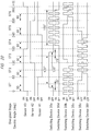
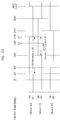
- the drive patterns of the switching elements 38a to 38f in the weak field control which is the second energization control, will be described on the basis of FIG. 19 .
- the weak field control is executed when the wiper arm 15 is moved in the forward path; and, when the wiper arm 15 is moved in the return path, the first energization control is executed.
- the energization stage ST1 to the energization stage ST6 and the electric angle 0° to the electric angle 360° are shown.
- the on/off timing of the switching signals of the sensors 41 to 43 are the same as the on/off timing of the switching signals of the sensors 41 to 43 in FIG. 17 .
- FIG. 19 shows the drive patterns of the switching elements 38a to 38f corresponding to the forward path of the wiper arm 15, and the control timing of the switching elements 38a to 38f shown in FIG. 19 is forward, in other words, by the amount corresponding to the section of an electric angle 30° compared with the control timing of the switching elements 38a to 38f shown in FIG. 7 .
- the positive-electrode-side switching element 38a of the U-phase is constantly turned on in the section of an electric angle 120° from the timing of an electric angle 15° to the timing of an electric angle 135° and is alternately switched to "on” and “off' in the section of an electric angle 120° from the timing of an electric angle 195° to the timing of an electric angle 315°.
- the negative-electrode-side switching element 38d of the U-phase is alternately switched to "on” and "off' in the section of an electric angle 120° from the timing of the electric angle 195° to the timing of the electric angle 315°.
- the positive-electrode-side switching element 38b of the V-phase is alternately switched to "on” and “off' in the section of an electric angle 120° from the timing of the electric angle 315° to the timing of the electric angle 75°, and the positive-electrode-side switching element 38b of the V-phase is constantly turned on while it is turned on at the timing of the electric angle 135° and turned off at the timing of an electric angle 255°.
- the negative-electrode-side switching element 38e of the V-phase is alternately switched to "on” and “off” in the section of an electric angle 120° from the timing of the electric angle 315° to the timing of the electric angle 75°.
- the positive-electrode-side switching element 38c of the W-phase is constantly turned on in the section of an electric angle 120° from the timing of the electric angle 255° to the timing of the electric angle 15°, the positive-electrode-side switching element 38c of the W-phase is alternately switched to "on” and “off' in the section of an electric angle 120° from the timing of the electric angle 75° to the timing of the electric angle 195°, and the negative-electrode-side switching element 38f of the W-phase is alternately switched to "on” and "off' in the section of an electric angle 120° from the timing of the electric angle 75° to the timing of the electric angle 195°.
- FIG. 9 is a diagram showing characteristics of the brushless motor 18.
- the rotation number of the brushless motor 18 is shown by a vertical axis
- the torque of the brushless motor 18 is shown by a horizontal axis.
- FIG. 9 shows an example of the characteristics for the low-speed mode and an example of high-speed mode characteristics. It is possible to switch between the low-speed mode and an example of high-speed mode when the driver manipulates the wiper switch 44 and selects the low-speed mode or the high-speed mode.
- a single characteristic is present at the position shown by a solid line so that the rotation number and torque corresponding to the low-speed mode characteristic of FIG. 9 can be obtained when the rating thereof is set. Therefore, if the low-speed mode is selected, the required rotation number and torque can be obtained in the range equal to and blow the single characteristic by executing the first energization control.
- the single characteristic is the target output of the case in which the actual vehicle speed of the vehicle 10 is equal to or less than a reference vehicle speed, in other words, is the characteristic that satisfies the low-speed mode.
- An apparent characteristic is the target output of the case in which the actual vehicle speed of the vehicle 10 exceeds the reference vehicle speed, in other words, is the characteristic that satisfies the high-speed mode.
- the target output can be expressed by the rotation number and torque of the rotor 27.
- the conditions that determine the target output include various conditions such as the detection signals of the wiper switch 44, the detection signals of the vehicle-speed sensor 45, and the load of the wiper arm 15.
- the rotation number and torque exceeding the single characteristic can be obtained by executing the weak field control or the second energization control by the control circuit 50.
- the characteristic of the brushless motor 18 is equivalent to the presence at the positions shown by a dashed-dotted line in FIG. 9 in terms of appearance.
- the brushless motor 18 can be subjected to determination of the rating thereof while using the low-speed mode as a reference in terms of design, and the size of the brushless motor 18 can be reduced as much as possible.
- the fact that the rotation number of the brushless motor 18 can be increased and the torque can be increased without changing the current value means that a torque constant is relatively increased.
- the brushless motor 18 of this embodiment can generate high torque as much as possible with smaller electric power consumption, and motor efficiency is improved.
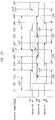
- the third energization control is executed when the wiper arm 15 is moved in the forward path; and, when the wiper arm 15 is moved in the return path, the first energization control is executed.
- the control circuit 50 detects in which one of the forward path and the return path the wiper arm 15 is moved.
- FIG. 20 also shows the energization stage ST1 to the energization stage ST6 and the electric angle 0° to the electric angle 360° as well as FIG. 17 .
- the on/off timing of the switching signals of the sensors 41 to 43 is the same as the on/off timing of the switching signals of the sensors 41 to 43 in FIG. 17 .
- the control timing of the switching elements 38a to 38f shown in FIG. 20 is advanced by the amount corresponding to the section of an electric angle 15° compared with the control timing of the switching elements 38a to 38f shown in FIG. 17 . This point is the same as the weak field control.
- the positive-electrode-side switching element 38a of the U-phase is constantly turned on in the section of an electric angle 150° from the timing of the electric angle 15° to the timing of an electric angle 165° and is alternately switched to "on” and “off' in the section of an electric angle 150° from the timing of the electric angle 195° to the timing of an electric angle 345°.
- the negative-electrode-side switching element 38d of the U-phase is alternately switched to "on” and "off' in the section of an electric angle 150° from the timing of the electric angle 195° to the timing of the electric angle 345°.
- the positive-electrode-side switching element 38b of the V-phase is alternately switched to "on” and “off' in the section of an electric angle 150° from the timing of the electric angle 315° to the timing of an electric angle 105°. Furthermore, the positive-electrode-side switching element 38b of the V-phase is turned on at the timing of the electric angle 135° and is constantly turned on in the section of an electric angle 150° until it is turned off at the timing of an electric angle 285°. On the other hand, the negative-electrode-side switching element 38e of the V-phase is alternately switched to "on” and "off” in the section of an electric angle 150° from the timing of the electric angle 315° to the timing of the electric angle 105°.
- the positive-electrode-side switching element 38c of the W-phase is constantly turned on in the section of an electric angle 150° from the timing of the electric angle 255° to the timing of the electric angle 45°, the positive-electrode-side switching element 38c of the W-phase is alternately switched to "on” and “off' in the section of an electric angle 150° from the timing of the electric angle 75° to the timing of an electric angle 225°, and the negative-electrode-side switching element 38c of the W-phase is alternately switched to "on” and "off' in the section of an electric angle 150° from the timing of the electric angle 75° to the timing of the electric angle 225°.
- the section of the electric angle 150° in which each of the switching elements 38a to 38f is turned on is longer by the amount corresponding to an electric angle 30° than the section of the electric angle 120° in which each of the switching elements 38a to 38f is turned on in the first energization control and the weak field control. In other words, it is longer by the amount corresponding to an electric angle 15° at each of the beginning and the end of the section of the electric angle 120°.
- the drive apparatus 37 can carry out control as described below.
- a time chart of FIG. 21 shows electric angles by the sections each corresponding to 60° for the sake of convenience.
- the ideal waveforms of the switching signals of the sensors 41 to 43 switch edges from “on” to “off”, and switch edges from "off' to "on” at every electric angle 60°.
- the drive apparatus 37 estimates the edge switching timing which occurs thereafter.
- the edge switching timing ahead by an electric angle 120° is calculated at every switching of edge timing
- the edge switching timing of the switching signal of the sensor 42 of the V-phase is estimated.
- the edge switching timing of the switching signal of the sensor 41 of the W-phase is estimated.
- the edge switching timing of the switching signal of the sensor 43 of the U-phase is estimated.
- a method of calculating the ideal edge switching timing of the sensor 42 of the V-phase ahead by the electric angle 120° on the basis of the edge switching timing of the switching signal of the sensor 43 of the U-phase can be expressed by the following Equations (1) and (2).
- the time corresponding to the electric angle 120 ° ⁇ t 120 ⁇ t 180 ⁇ 0.67
- the timing ahead by the electric angle 120 ° p 120 ⁇ t120 + FRT
- the drive apparatus 37 of this embodiment obtains, by an electric angle, the phase difference between the ideal switching timing and the switching timing of the actually detected switching signal and corrects the phase difference, thereby obtaining the ideal waveform of the switching signal.
- the drive apparatus 37 controls on/off of the switching elements 38a to 38f on the basis of the ideal waveforms of the switching signals.
- the switching signals of the sensors 41 to 43 shown in FIG. 23 are the same as the switching signals of the sensors 41 to 43 shown in FIG. 17 .
- the time chart of FIG. 23 shows electric angles by the sections each corresponding to 60° for the sake of convenience.
- the ideal waveform of the switching signal of the sensor 43 is turned on at the electric angle 0°, continues to be on for the section of an electric angle 180°, and is then switched to off at the timing of the electric angle 180°. More specifically, the ideal waveform of the switching signal of the sensor 43 is turned off at the timing of the electric angle 180° (p1) delayed by a section of an electric angle 60° from the timing of the electric angle 120° at which the switching signal of the sensor 42 is turned on.
- the drive apparatus 37 is constantly detecting time ⁇ t180 corresponding to the section of the electric angle 180° in the switching signal of the sensor 43. Then, ideal time ⁇ t60 corresponding to the section of the ideal electric angle 60° from the timing at which the sensor 42 is turned on to the timing at which the sensor 43 is turned off is calculated. Furthermore, the drive apparatus 37 calculates actual measurement time ⁇ trea160 corresponding to the section of the actual electric angle 90° from the timing at which the sensor 42 is turned on to the timing at which the sensor 43 is turned off. Furthermore, the drive apparatus 37 obtains an adjustment value (correction value) "AdjPhase" of the switching signal of the sensor 43 from the difference between the ideal time ⁇ t60 and the actual measurement time ⁇ trea160. This process can be expressed by Equation (4) and Equation (5).
- ⁇ t 60 ⁇ t 180 ⁇ 0.334
- AdjPhase ⁇ t 60 ⁇ ⁇ treal 60
- 0.334 is a coefficient of the section of the electric angle 60° with respect to the section of the electric angle 180° in which on or off of the switching signal is continued.
- the drive apparatus 37 carries out a process of correcting the off-timing of the switching signal of the sensor 43 to the timing of the electric angle 180° (p1), which has been advanced by the section of the electric angle 30° from the electric angle 210°.
- the section of the electric angle from the timing at which the switching signal of the sensor 42 is turned on to the timing at which the switching signal of the sensor 43 is turned off can be changed to the ideal electric angle 60°.
- the switching signals of the sensors 41 to 43 shown in FIG. 24 are the same as the switching signals of the sensors 41 to 43 shown in FIG. 17 .
- the timing chart of FIG. 24 shows electric angles by the sections each corresponding to 60° for the sake of convenience. As shown by broken lines, the ideal waveform of the switching signal of the sensor 41 is turned off at the electric angle 60°, maintains to be off for the section of an electric angle 180°, and is then switched to on at the electric angle 240°.
- the ideal waveform of the switching signal of the sensor 41 is turned on at the timing of the electric angle 240° (p1) which is delayed by the section of an electric angle 120° from the timing of the electric angle 120° at which the switching signal of the sensor 42 is turned on.
- the control circuit 50 turns on the switching signal of the sensor 43 at the timing of the electric angle 360° (p2) having an interval of a section of an electric angle 120° from the electric angle 240°, which is the on-timing of the corrected switching signal of the sensor 41.
- the section of the electric angle from the timing at which the switching signal of the sensor 41 is turned on to the timing at which the switching signal of the sensor 43 is turned on can be changed to the ideal electric angle 120°.
- This Equation (8) means that it is possible to obtain, by using the adjustment value (correction value) "AdjPhase", the timing P2 of the electric angle of the switching signal which is turned on at the timing having an interval of an electric angle 120° (p120) from the timing of the electric angle 240°.
- step S1 If the drive apparatus 37 detects the edge switching timing of any of the sensor among the sensor 43 of the U-phase, the sensor 42 of the V-phase, and the sensor of the W-phase (step S1), the drive apparatus 37 executes the processes of step S2 to step S5.
- step S2 to step S4 mean to update the measurement time of the one-time-before to three-time-before electric angles 60°.
- the drive apparatus 37 acquires the latest measurement time corresponding to the section of the electric angle 60° in step S5.
- step S6 subsequent to step S5, the drive apparatus 37 judges whether it is the timing at which the edge of the switching signal of the sensor 43 of the U-phase is switched or not. If the drive apparatus 37 judges YES in step S6, the drive apparatus 37 proceeds to step S7. For example, the example in which YES is judged in step S6 is at the timing of the electric angle 360° of FIG. 22 . Then, in step S7, the drive apparatus 37 obtains the time ⁇ t120 corresponding to the section of the electric angle 120° from the time ⁇ t180 corresponding to the section of the electric angle 180° of the switching signal of the sensor 43.
- step S7 the drive apparatus 37 executes the processes of step S8 to step S11, executes the process of step S17, and terminates a control routine.
- the processes of step S8 to step S11 are the processes described by referencing the time chart of FIG. 23 .
- the process of step S8 is the process of obtaining the ideal time ⁇ t60 corresponding to the section of the ideal electric angle 60° from the time ⁇ t180 corresponding to the section of the electric angle 180° of the switching signal of the sensor 43 of the U-phase.
- step S9 is the process of obtaining the actual measurement time ⁇ trea160 corresponding to the actual section of the electric angle 60° from the timing at which the sensor 42 is turned on to the timing at which the sensor 43 is turned off.
- ⁇ t60' has the same meaning as ⁇ trea160 in Equation (5)
- step S11 the process of correcting the off-timing of the switching signal of the sensor 43 to the timing of the electric angle 180° (p1), which has been advanced by the section of the electric angle 30° from the electric angle 210°.
- step S17 selects and executes any of the first energization control, the weak field control, and the third energization control by using the switching signal, which serves as a reference, and the corrected switching signal.
- step S6 the drive apparatus 37 judges NO in step S6 whether it is the timing at which the switching signal of the sensor 41 is switched or not. If the drive apparatus 37 judges YES in step S12, the drive apparatus 37 executes the processes of step S13 to step S16 and, after step S17, terminates the control routine.
- step S13 is the process of obtaining the ideal time ⁇ t120 corresponding to the ideal section of the electric angle 120°from the time ⁇ t180 corresponding to the section of the electric angle 180° of the switching signal of the sensor 41 of the W-phase.
- step S15 is the process of obtaining the phase difference (shifting) between the ideal section of the electric angle 120° and the actual section of the electric angle 90°. This process is expressed by the following equation.
- the phase difference ⁇ t 120 ⁇ ⁇ t 120 ' .
- step S16 the process of correcting the timing of the switching signal of the sensor 41 to the timing of the electric angle 240° (p1), which is delayed by the section of the electric angle 30° from the electric angle 210°, is carried out.
- the motor apparatus 17 can correct the switching signal of the sensors 41 or 43 on the basis of the switching signal of the sensor 42. Therefore, even if there is an error in the mutual distances between the sensors 41, 42, and 43 with respect to ideal distances, the first energization control, the weak field control, or the third energization control can be appropriately carried out by using the corrected switching signal. Therefore, in accordance with the conditions such as the movement position, movement direction, load, mode, etc. of the wiper arm 15, the rotation number, the torque, etc. of the rotor 27 of the brushless motor 18 can be obtained. Therefore, efficiency of the motor apparatus 17 can be improved, noise can be suppressed, and vibrations can be avoided.
- the sensors 41, 42, and 43 can be disposed on the same plane of the control board 36. Therefore, dedicated sensor supporting members for attaching the three sensors are not required to be provided around the rotor. Therefore, lead wires, etc. for connecting the three sensors provided at the dedicated sensor supporting members and the control circuit are not required to be provided. Therefore, the size and cost of the motor apparatus 17 can be reduced.
- the drive apparatus 37 described in the above described second embodiment corresponds to a signal correcting unit and an element control unit of the present invention.
- the timing of the electric angle 30° at which the switching element 38a is turned on corresponds to first timing of the present invention
- the timing of the electric angle 15° at which the switching element 38a is turned on in the weak field control or the third energization control corresponds to second timing of the present invention.
- the speed reduction mechanism 19 and the pivot shaft 14 correspond to a power transmitting mechanism of the present invention.
- step S7 to step S11 and step S13 to step S16 correspond to a first step of the present invention
- step S17 corresponds to a second step of the present invention.
- the drive apparatus of the present invention is not limited to that of the second embodiment, and it goes without saying that various modifications can be made within the range not deviating from the appended claims.
- the brushless motor of the present invention includes the structure of a star connection in which armature coils are connected in Y shapes.
- the brushless motor of the present invention includes one in which the rotor has an IPM (Interior Permanent Magnet) structure. In the IPM structure, permanent magnets are buried in the rotor core.
- the first period is not limited to the electric angle 120°, but may be less than the electric angle 120°, or may exceed the electric angle 120°.
- the brushless motor of the present invention includes the inner-rotor-type structure in which the rotor is disposed in the inner side of the stator and an outer-rotor-type structure in which the rotor is disposed in the outer side of the stator.
- the wiper apparatus of the present invention includes a wiper apparatus in which the wiper blade wipes off a rear glass.
- the wind glass of the wiper apparatus of the present invention includes a windshield and a rear glass.
- the wiper apparatus of the present invention includes a configuration in which two wiper arms are singularly driven by a single brushless motor.
Landscapes
- Engineering & Computer Science (AREA)
- Mechanical Engineering (AREA)
- Power Engineering (AREA)
- Control Of Motors That Do Not Use Commutators (AREA)
Claims (8)
- Wischervorrichtung, umfassend:einen bürstenlosen Motor (18), der Spulen (U1, U2, V1, V2, W1, W2) mit Strom versorgt und einen Rotor (27) in Drehung versetzt;einen Wischerarm (15), der Energie von dem Rotor des bürstenlosen Motors empfängt und so bewegt wird, dass er eine Fensterscheibe eines Fahrzeugs (10) wischt; undeine Steuereinheit (37), die schaltet und selektiv Folgendes ausführt:eine erste Erregungssteuerung, um das Erregen der Spulen zu einem ersten Zeitpunkt zu starten und das Erregen für eine erste Zeitdauer fortzusetzen, um die Drehzahl des Rotors zu steuern; undeine zweite Erregungssteuerung, um das Erregen der Spulen zu einem zweiten Zeitpunkt zu starten, der um einen elektrischen Winkel in Bezug auf den ersten Zeitpunkt vorgerückt ist, und um das Erregen für einen zweiten Zeitraum fortzusetzen, der länger als der erste Zeitraum ist, um die Drehzahl des Rotors zu steuern,dadurch gekennzeichnet, dassder zweite Zeitpunkt in Bezug auf den ersten Zeitpunkt um einen elektrischen Winkel, der gleich oder größer als 30 Grad und gleich oder kleiner als 60 Grad ist, vorgerückt ist,der erste Zeitraum auf einen elektrischen Winkel von 120 Grad eingestellt ist,der zweite Zeitraum basierend auf dem elektrischen Winkel, um den der zweite Zeitpunkt in Bezug auf den ersten Zeitpunkt vorgerückt ist, innerhalb eines Bereichs eingestellt ist, der gleich oder größer als ein elektrischer Winkel von 135 Grad und gleich oder kleiner als ein elektrischer Winkel von 165 Grad ist,eine Drehmomentwelligkeitsrate, wenn die zweite Erregungssteuerung ausgeführt wird, stärker reduziert wird als eine Drehmomentwelligkeitsrate, wenn die erste Erregungssteuerung ausgeführt wird, unddie Steuereinheit (37) aufweist:eine Modusumschalteinheit (37), die eines von einem Niedriggeschwindigkeitsmodus schaltet und auswählt, um den Wischerarm mit einer im Voraus bestimmten Geschwindigkeit zu bewegen, und einen Hochgeschwindigkeitsmodus, um den Wischerarm mit einer Geschwindigkeit zu bewegen, die schneller als der Niedriggeschwindigkeitsmodus ist, und einen von den Niedriggeschwindigkeits- und Hochgeschwindigkeitsmodi auswählt; undeine Vielzahl von Sensoren (41, 42, 43) zum Erkennen von Drehphasen des Rotors,wobei gemäß den Bedingungen, basierend auf dem Niedriggeschwindigkeits- oder Hochgeschwindigkeitsmodus, ausgewählt durch die Modusumschalteinheit, und einer Betätigungslast des Wischerarms, die aus den Ausgangssignalen der Sensoren geschätzt wird, die erste Erregungssteuerung, deren Stromwellenform zu einer Rechteckwelle gemacht wird, ausgeführt wird, oder die zweite Erregungssteuerung, deren Stromwellenform glatter als die Rechteckwelle ist, ausgeführt wird, und der um den bürstenlosen Motor herum erzeugte abgestrahlte Schall reduziert wird.
- Wischervorrichtung nach Anspruch 1, wobei der Rotor (27) aufweist:eine Rotorwelle (28), die einen Rotorkern aufweist, der an einer Außenumfangsfläche davon befestigt ist; undvier Permanentmagnete (29N, 29S), die an der Außenumfangsfläche des Rotorkerns entlang einer Umfangsrichtung der Rotorwelle angeordnet sind,die Spulen an einem Stator (21) bereitgestellt sind, der außerhalb des Rotors angeordnet ist,der Stator sechs Zähne (23) aufweist, die in Abständen in Umfangsrichtung der Rotorwelle angeordnet sind, wobei die Spulen um die Zähne gewickelt sind,die Spulen, die um die Zähne gewickelt sind, sechs Schlitze aufweisen, und elektrisch in Dreieckschaltung miteinander verbunden sind, unddie Steuereinheit (37) durch die erste Erregungssteuerung die Spulen mit einem Strom der Rechteckwelle versorgt, und durch die zweite Erregungssteuerung die Spulen mit einem Strom einer glatteren Welle als die Rechteckwelle versorgt, wodurch der Schalldruck in einem Fall, in dem die zweite Erregungssteuerung ausgeführt wird, geringer ist als der Schalldruck in einem Fall, in dem die erste Erregungssteuerung ausgeführt wird.
- Wischervorrichtung nach Anspruch 1, wobei
die Steuereinheit (37) die erste Erregungssteuerung ausführt, um die Spulen mit einem Rechteckstrom zu versorgen, und die zweite Erregungssteuerung ausführt, um die Spulen mit einem Strom zu versorgen, der eine glattere Wellenform aufweist als der Rechteckstrom, um den Schalldruck des Schalls, der von dem bürstenlosen Motor abgestrahlt werden soll, im Vergleich zum Schalldruck des Schalls, der von dem bürstenlosen Motor durch die erste Erregungssteuerung abgestrahlt werden soll, zu verringern. - Wischervorrichtung nach Anspruch 1,
wobei die Steuereinheit (37) die zweite Erregungssteuerung ausführt, wenn der Hochgeschwindigkeitsmodus ausgewählt ist. - Wischervorrichtung nach einem der Ansprüche 1 bis 4, ferner umfassend eine Motorvorrichtung (17), einschließlich:einen Stator (21), der die Spulen außerhalb des Rotors (27) aufweist;den Rotor (27), der durch ein rotierendes Magnetfeld gedreht wird, das durch den Stator (21) gebildet wird;den bürstenlosen Motor (18);eine Antriebsvorrichtung (37), die den bürstenlosen Motor (18) steuert; undeine Steuerplatine (36), die mit der Antriebsvorrichtung bereitgestellt wird,wobei die Vielzahl von Sensoren (41, 42, 43) an der Steuerplatine (36) so angebracht sind, dass sie in einer Drehrichtung des Rotors (27) angeordnet sind, und in der Phase voneinander verschieden sind, unddie Antriebsvorrichtung (37) umfasst:eine Wechselrichterschaltung (38), die eine Vielzahl von Schaltelementen (38a) aufweist, die die mit den Spulen verbundenen Stromversorgungspfade getrennt ein- oder ausschalten, um das Erregen jeder der Spulen zu steuern;eine Signalkorrektureinheit (37), die das Ausgangssignal von einem der Sensoren als Referenzsignal verwendet und die Ausgangssignale der verbleibenden Sensoren basierend auf dem Referenzsignal korrigiert; undeine Elementsteuereinheit (37), die die Schaltelemente durch Schalten der ersten Erregungssteuerung oder der zweiten Erregungssteuerung steuert.
- Wischervorrichtung nach Anspruch 5, wobei
die Elementsteuereinheit (37) eine dritte Erregungssteuerung ausführt, um das Erregen der Spulen für die Zeit fortzusetzen, die länger ist als die Zeit, in der das Erregen der Spulen in der zweiten Erregungssteuerung fortgesetzt wird. - Wischervorrichtung nach Anspruch 5 oder 6, wobei die Elementsteuereinheit (37) Daten von Erregungsmustern der Spulen darin gespeichert aufweist.
- Steuerungsverfahren für die Wischervorrichtung nach Anspruch 6, wobei das Steuerungsverfahren die folgenden Schritte umfasst:Verwenden des Ausgangssignals von einem der Sensoren (41, 42, 43) als das Referenzsignal, und Korrigieren der Ausgangssignale der verbleibenden Sensoren basierend auf dem Referenzsignal;Steuern der Schaltelemente (38a) basierend auf dem Referenzsignal und den korrigierten Ausgangssignalen, sodass die erste Erregungssteuerung, die zweite Erregungssteuerung oder die dritte Erregungssteuerung auch dann geschaltet und selektiv ausgeführt wird, wenn die gegenseitigen Abstände zwischen den Sensoren in Bezug auf die idealen Abstände fehlerhaft sind,Vorverlegen des zweiten Zeitpunkts in Bezug auf den ersten Zeitpunkt durch einen elektrischen Winkel, der gleich oder größer als 30 Grad und gleich oder kleiner als 60 Grad ist;Einstellen des ersten Zeitraums auf einen elektrischen Winkel von 120 Grad;Einstellen des zweiten Zeitraums basierend auf dem elektrischen Winkel, um den der zweite Zeitpunkt in Bezug auf den ersten Zeitpunkt vorgerückt ist innerhalb eines Bereichs, der gleich oder größer als ein elektrischer Winkel von 135 Grad und gleich oder kleiner als ein elektrischer Winkel von 165 Grad ist;Verringern einer Drehmomentwelligkeitsrate, wenn die zweite Erregungssteuerung ausgeführt wird, stärker als eine Drehmomentwelligkeitsrate, wenn die erste Erregungssteuerung ausgeführt wird; undSchalten und Auswählen eines von einem Niedriggeschwindigkeitsmodus, um den Wischerarm mit einer im Voraus bestimmten Geschwindigkeit zu bewegen, und einem Hochgeschwindigkeitsmodus, um den Wischerarm mit einer Geschwindigkeit zu bewegen, die schneller als der Niedriggeschwindigkeitsmodus ist, und Auswählen eines von den Niedriggeschwindigkeits- und Hochgeschwindigkeitsmodi durch die Modusumschalteinheit (37); undErkennen von Rotationsphasen des Rotors durch die Vielzahl von Sensoren (41, 42, 43);wobei, gemäß Bedingungen basierend auf dem Niedriggeschwindigkeits- oder Hochgeschwindigkeitsmodus, ausgewählt durch die Modusumschalteinheit, und einer Betätigungslast des Wischerarms, geschätzt aus den Ausgangssignalen der Sensoren, die erste Erregungssteuerung, deren Stromwellenform zu einer Rechteckwelle gemacht wird, ausgeführt wird, oder die zweite Erregungssteuerung, deren Stromwellenform glatter als die Rechteckwelle ist, ausgeführt wird, und der abgestrahlte Schall, der um den bürstenlosen Motor erzeugt wird, reduziert wird.
Applications Claiming Priority (3)
| Application Number | Priority Date | Filing Date | Title |
|---|---|---|---|
| JP2013267085A JP6239378B2 (ja) | 2013-12-25 | 2013-12-25 | ワイパ装置及びワイパ装置の制御方法 |
| JP2013267084A JP6239377B2 (ja) | 2013-12-25 | 2013-12-25 | ブラシレスモータ及びワイパ装置 |
| PCT/JP2014/083821 WO2015098789A1 (ja) | 2013-12-25 | 2014-12-22 | ブラシレスモータ及びワイパ装置、モータ装置及びモータ装置の制御方法 |
Publications (3)
| Publication Number | Publication Date |
|---|---|
| EP3089350A1 EP3089350A1 (de) | 2016-11-02 |
| EP3089350A4 EP3089350A4 (de) | 2017-11-22 |
| EP3089350B1 true EP3089350B1 (de) | 2021-09-15 |
Family
ID=53478644
Family Applications (1)
| Application Number | Title | Priority Date | Filing Date |
|---|---|---|---|
| EP14874596.1A Active EP3089350B1 (de) | 2013-12-25 | 2014-12-22 | Wischervorrichtung und wischervorrichtungsteuerungsverfahren |
Country Status (4)
| Country | Link |
|---|---|
| US (2) | US20160322921A1 (de) |
| EP (1) | EP3089350B1 (de) |
| CN (1) | CN105850027A (de) |
| WO (1) | WO2015098789A1 (de) |
Families Citing this family (7)
| Publication number | Priority date | Publication date | Assignee | Title |
|---|---|---|---|---|
| JPWO2017159214A1 (ja) * | 2016-03-16 | 2019-01-24 | 株式会社ミツバ | モータ制御装置及びモータユニット |
| FR3059174B1 (fr) * | 2016-11-21 | 2019-01-25 | Valeo Systemes D'essuyage | Moto-reducteur, systeme d'essuyage et procede de commande associes |
| JP6816576B2 (ja) * | 2017-03-13 | 2021-01-20 | 株式会社デンソー | ワイパ装置 |
| JP6921687B2 (ja) * | 2017-08-31 | 2021-08-18 | 株式会社ミツバ | ワイパ装置 |
| FR3074979B1 (fr) * | 2017-12-08 | 2021-07-30 | Valeo Systemes Dessuyage | Moteur electrique a courant continu sans balais pour systeme d'essuyage de vehicule automobile |
| JP2022111673A (ja) * | 2021-01-20 | 2022-08-01 | 株式会社アイシン | 車両用開閉体制御装置 |
| CN113252743B (zh) * | 2021-06-02 | 2024-05-17 | 爱德森(厦门)电子有限公司 | 一种利用电磁原理检测电化学腐蚀防护层的方法及装置 |
Family Cites Families (45)
| Publication number | Priority date | Publication date | Assignee | Title |
|---|---|---|---|---|
| JPH01142357U (de) | 1988-03-25 | 1989-09-29 | ||
| US6111378A (en) * | 1995-04-28 | 2000-08-29 | Ut Automotive Dearborn, Inc. | Window wiper motor system for an automotive vehicle |
| US6002250A (en) * | 1996-05-13 | 1999-12-14 | Mitutoyo Corporation | Electronic linear scale using a self-contained, low-power inductive position transducer |
| KR20010058813A (ko) | 1999-12-30 | 2001-07-06 | 문승 | 차량용 와이퍼의 구동장치 |
| DE10011842B4 (de) | 2000-03-10 | 2011-02-24 | Volkswagen Ag | Scheibenwischeranlage mit einem Reversiermotor |
| DE10045573A1 (de) | 2000-09-14 | 2002-04-04 | Bosch Gmbh Robert | Wischerantrieb |
| DE10153173B4 (de) | 2001-02-27 | 2019-09-05 | Robert Bosch Gmbh | Elektrischer Antrieb mit einem Wärmeleitelement zur Wärmeabführung von einer elektrischen Schaltung |
| JP3904963B2 (ja) | 2001-05-21 | 2007-04-11 | アスモ株式会社 | モータ制御装置 |
| JP3888247B2 (ja) * | 2002-07-15 | 2007-02-28 | 松下電器産業株式会社 | モータ駆動装置 |
| JP4543669B2 (ja) * | 2003-02-18 | 2010-09-15 | パナソニック株式会社 | モータ駆動装置、モータ、機器 |
| EP1576720B1 (de) * | 2003-02-18 | 2007-06-06 | Matsushita Electric Industrial Co., Ltd. | Motorantriebsvorrichtung, von derselben vorrichtung angetriebener motor und vorrichtung für den gebrauch desselben motors |
| JP2005086855A (ja) | 2003-09-05 | 2005-03-31 | Showa Corp | 電動パワーステアリング装置のモータ制御回路組付構造 |
| EP1663740A4 (de) | 2003-09-15 | 2010-04-14 | Magna Closures Inc | Umkehrmotor-windschutzscheibenwischersystem |
| JP4319597B2 (ja) | 2003-11-07 | 2009-08-26 | アスモ株式会社 | モータ装置、及びワイパモータ |
| JP2005168133A (ja) | 2003-12-01 | 2005-06-23 | Mitsuba Corp | 電動モータ |
| JP4545428B2 (ja) * | 2003-12-16 | 2010-09-15 | 株式会社ミツバ | 電動モータ |
| US7687945B2 (en) | 2004-09-25 | 2010-03-30 | Bluwav Systems LLC. | Method and system for cooling a motor or motor enclosure |
| JP2006197762A (ja) * | 2005-01-17 | 2006-07-27 | Toshiba Lsi System Support Kk | モータのセンサ信号補正回路 |
| JP4129875B2 (ja) | 2005-03-08 | 2008-08-06 | 東京パーツ工業株式会社 | 減速機構付き電動モータ |
| JP4667132B2 (ja) * | 2005-06-17 | 2011-04-06 | ローム株式会社 | モータ駆動装置及びこれを用いた電気機器 |
| JP4664154B2 (ja) | 2005-08-23 | 2011-04-06 | アスモ株式会社 | モータ |
| JP2007097352A (ja) | 2005-09-30 | 2007-04-12 | Mitsuba Corp | 電動モータ |
| JP5006537B2 (ja) | 2005-11-17 | 2012-08-22 | 株式会社ミツバ | ワイパモータ |
| JP2007202391A (ja) | 2005-12-28 | 2007-08-09 | Mitsuba Corp | 速度切り替え式モータ |
| JP2008103618A (ja) | 2006-10-20 | 2008-05-01 | Mitsuba Corp | 回路基板 |
| DE102006060621A1 (de) | 2006-12-21 | 2008-06-26 | Robert Bosch Gmbh | Elektrische Antriebsvorrichtung mit einer elektronischen Steuerungseinheit |
| US8453290B2 (en) * | 2006-12-26 | 2013-06-04 | Mitsuba Corporation | Wiper driving apparatus |
| JP5029170B2 (ja) | 2007-06-27 | 2012-09-19 | ダイキン工業株式会社 | 電子回路装置 |
| DE102007059905B4 (de) | 2007-12-12 | 2017-05-24 | Robert Bosch Gmbh | Scheibenwischerantrieb |
| JP5397652B2 (ja) | 2008-02-12 | 2014-01-22 | 株式会社ジェイテクト | 車両用操舵装置 |
| JP4912334B2 (ja) | 2008-02-15 | 2012-04-11 | 株式会社ミツバ | ワイパ装置 |
| CN101978576A (zh) * | 2008-03-19 | 2011-02-16 | 三洋电机株式会社 | 永久磁铁同步电动机 |
| CN101667770B (zh) * | 2008-09-03 | 2013-09-04 | 德昌电机(深圳)有限公司 | 一种燃料泵及其无刷直流马达 |
| WO2010034410A1 (de) | 2008-09-25 | 2010-04-01 | MAPAL Fabrik für Präzisionswerkzeuge Dr. Kress KG | Werkzeug zur spanenden bearbeitung |
| JP2010093977A (ja) | 2008-10-09 | 2010-04-22 | Asmo Co Ltd | 減速機構付きモータ |
| JP5522978B2 (ja) | 2009-06-12 | 2014-06-18 | 株式会社ミツバ | 減速機構付き電動モータ |
| JP5517650B2 (ja) | 2010-02-01 | 2014-06-11 | 三菱重工業株式会社 | インバータ一体型電動圧縮機 |
| CN103098366B (zh) * | 2010-07-12 | 2016-05-18 | 松下电器产业株式会社 | 相位偏移检测装置、马达驱动装置、无刷马达以及相位偏移检测方法 |
| EP2639119B1 (de) * | 2010-12-10 | 2019-05-01 | Mitsuba Corporation | Scheibenwischermotor |
| JP5572577B2 (ja) | 2011-03-30 | 2014-08-13 | 日立オートモティブシステムズ株式会社 | 電動モータの電子制御装置 |
| JP5943556B2 (ja) | 2011-05-30 | 2016-07-05 | 三菱電機株式会社 | ファン駆動用電動機 |
| DE102011077191A1 (de) | 2011-06-08 | 2012-12-13 | Robert Bosch Gmbh | Wischanlage für ein Fahrzeug |
| US9738259B2 (en) * | 2012-01-17 | 2017-08-22 | Nelson And Nelson Enterprises, Llc | Wiper with ice removal apparatus |
| JP5979924B2 (ja) | 2012-03-16 | 2016-08-31 | 株式会社ミツバ | ワイパ装置 |
| BR112014025606B1 (pt) * | 2012-04-16 | 2018-03-13 | Mitsuba Corporation | Aparelho Limpador |
-
2014
- 2014-12-22 EP EP14874596.1A patent/EP3089350B1/de active Active
- 2014-12-22 US US15/107,658 patent/US20160322921A1/en not_active Abandoned
- 2014-12-22 CN CN201480071145.9A patent/CN105850027A/zh active Pending
- 2014-12-22 WO PCT/JP2014/083821 patent/WO2015098789A1/ja not_active Ceased
-
2018
- 2018-04-20 US US15/958,095 patent/US10594233B2/en active Active
Also Published As
| Publication number | Publication date |
|---|---|
| EP3089350A4 (de) | 2017-11-22 |
| US10594233B2 (en) | 2020-03-17 |
| CN105850027A (zh) | 2016-08-10 |
| EP3089350A1 (de) | 2016-11-02 |
| US20160322921A1 (en) | 2016-11-03 |
| US20180323733A1 (en) | 2018-11-08 |
| WO2015098789A1 (ja) | 2015-07-02 |
Similar Documents
| Publication | Publication Date | Title |
|---|---|---|
| US10594233B2 (en) | Brushless motor, wiper apparatus, motor apparatus and control method for motor apparatus | |
| CN104272579B (zh) | 无刷电动机及雨刮装置 | |
| US10439527B2 (en) | Motor control device | |
| US8054030B2 (en) | Permanent magnet AC motor systems and control algorithm restart methods | |
| EP2704307A1 (de) | Vorrichtung zur steuerung eines bürstenlosen motors und verfahren zur steuerung eines bürstenlosen motors | |
| EP1265348A1 (de) | Verfahren zum Antreiben eines bürstenlosen Gleichstrommotors und Gerät zum präzisen Steuern der Rotor-Startposition | |
| CN103918173B (zh) | 同步电动机控制系统 | |
| JP6239377B2 (ja) | ブラシレスモータ及びワイパ装置 | |
| JP2013198188A (ja) | ブラシレスモータ及びワイパ装置 | |
| US9000704B2 (en) | Three-phase motor driving apparatus and three-phase motor driving method | |
| US10432114B2 (en) | Electric motor, gear motor, wiping system and associated control method | |
| EP3331152B1 (de) | Motorsteuerungsverfahren und motorsteuerungsvorrichtung | |
| KR20160098890A (ko) | 자동차의 전동식 파워 스티어링 시스템 및 방법 | |
| JP6239378B2 (ja) | ワイパ装置及びワイパ装置の制御方法 | |
| CN109379901B (zh) | 无刷电动机以及控制方法 | |
| US9035580B2 (en) | AC motor control apparatus | |
| EP3450266B1 (de) | Wischervorrichtung | |
| JP2001145381A (ja) | モータの制御装置 | |
| EP2704308A1 (de) | Vorrichtung zur steuerung eines bürstenlosen motors und verfahren zur steuerung eines bürstenlosen motors | |
| JP2001128479A (ja) | 直流無整流子モータの駆動制御方法および装置 | |
| US12273065B2 (en) | Motor control device and electric pump device | |
| JP2001128483A (ja) | 直流無整流子モータの駆動制御方法および装置 |
Legal Events
| Date | Code | Title | Description |
|---|---|---|---|
| PUAI | Public reference made under article 153(3) epc to a published international application that has entered the european phase |
Free format text: ORIGINAL CODE: 0009012 |
|
| 17P | Request for examination filed |
Effective date: 20160623 |
|
| AK | Designated contracting states |
Kind code of ref document: A1 Designated state(s): AL AT BE BG CH CY CZ DE DK EE ES FI FR GB GR HR HU IE IS IT LI LT LU LV MC MK MT NL NO PL PT RO RS SE SI SK SM TR |
|
| AX | Request for extension of the european patent |
Extension state: BA ME |
|
| DAX | Request for extension of the european patent (deleted) | ||
| A4 | Supplementary search report drawn up and despatched |
Effective date: 20171019 |
|
| RIC1 | Information provided on ipc code assigned before grant |
Ipc: H02K 21/14 20060101ALI20171013BHEP Ipc: H02P 27/08 20060101ALI20171013BHEP Ipc: B60S 1/08 20060101ALI20171013BHEP Ipc: B60S 1/46 20060101ALI20171013BHEP Ipc: H02P 6/10 20060101AFI20171013BHEP Ipc: B60S 1/16 20060101ALI20171013BHEP Ipc: H02K 1/27 20060101ALI20171013BHEP |
|
| STAA | Information on the status of an ep patent application or granted ep patent |
Free format text: STATUS: EXAMINATION IS IN PROGRESS |
|
| 17Q | First examination report despatched |
Effective date: 20190628 |
|
| GRAP | Despatch of communication of intention to grant a patent |
Free format text: ORIGINAL CODE: EPIDOSNIGR1 |
|
| STAA | Information on the status of an ep patent application or granted ep patent |
Free format text: STATUS: GRANT OF PATENT IS INTENDED |
|
| INTG | Intention to grant announced |
Effective date: 20210416 |
|
| GRAS | Grant fee paid |
Free format text: ORIGINAL CODE: EPIDOSNIGR3 |
|
| GRAA | (expected) grant |
Free format text: ORIGINAL CODE: 0009210 |
|
| STAA | Information on the status of an ep patent application or granted ep patent |
Free format text: STATUS: THE PATENT HAS BEEN GRANTED |
|
| AK | Designated contracting states |
Kind code of ref document: B1 Designated state(s): AL AT BE BG CH CY CZ DE DK EE ES FI FR GB GR HR HU IE IS IT LI LT LU LV MC MK MT NL NO PL PT RO RS SE SI SK SM TR |
|
| REG | Reference to a national code |
Ref country code: CH Ref legal event code: EP Ref country code: GB Ref legal event code: FG4D |
|
| REG | Reference to a national code |
Ref country code: DE Ref legal event code: R096 Ref document number: 602014080186 Country of ref document: DE |
|
| REG | Reference to a national code |
Ref country code: IE Ref legal event code: FG4D |
|
| REG | Reference to a national code |
Ref country code: AT Ref legal event code: REF Ref document number: 1431316 Country of ref document: AT Kind code of ref document: T Effective date: 20211015 |
|
| REG | Reference to a national code |
Ref country code: LT Ref legal event code: MG9D |
|
| REG | Reference to a national code |
Ref country code: NL Ref legal event code: MP Effective date: 20210915 |
|
| PG25 | Lapsed in a contracting state [announced via postgrant information from national office to epo] |
Ref country code: LT Free format text: LAPSE BECAUSE OF FAILURE TO SUBMIT A TRANSLATION OF THE DESCRIPTION OR TO PAY THE FEE WITHIN THE PRESCRIBED TIME-LIMIT Effective date: 20210915 Ref country code: BG Free format text: LAPSE BECAUSE OF FAILURE TO SUBMIT A TRANSLATION OF THE DESCRIPTION OR TO PAY THE FEE WITHIN THE PRESCRIBED TIME-LIMIT Effective date: 20211215 Ref country code: FI Free format text: LAPSE BECAUSE OF FAILURE TO SUBMIT A TRANSLATION OF THE DESCRIPTION OR TO PAY THE FEE WITHIN THE PRESCRIBED TIME-LIMIT Effective date: 20210915 Ref country code: NO Free format text: LAPSE BECAUSE OF FAILURE TO SUBMIT A TRANSLATION OF THE DESCRIPTION OR TO PAY THE FEE WITHIN THE PRESCRIBED TIME-LIMIT Effective date: 20211215 Ref country code: HR Free format text: LAPSE BECAUSE OF FAILURE TO SUBMIT A TRANSLATION OF THE DESCRIPTION OR TO PAY THE FEE WITHIN THE PRESCRIBED TIME-LIMIT Effective date: 20210915 Ref country code: SE Free format text: LAPSE BECAUSE OF FAILURE TO SUBMIT A TRANSLATION OF THE DESCRIPTION OR TO PAY THE FEE WITHIN THE PRESCRIBED TIME-LIMIT Effective date: 20210915 Ref country code: RS Free format text: LAPSE BECAUSE OF FAILURE TO SUBMIT A TRANSLATION OF THE DESCRIPTION OR TO PAY THE FEE WITHIN THE PRESCRIBED TIME-LIMIT Effective date: 20210915 |
|
| REG | Reference to a national code |
Ref country code: AT Ref legal event code: MK05 Ref document number: 1431316 Country of ref document: AT Kind code of ref document: T Effective date: 20210915 |
|
| PG25 | Lapsed in a contracting state [announced via postgrant information from national office to epo] |
Ref country code: LV Free format text: LAPSE BECAUSE OF FAILURE TO SUBMIT A TRANSLATION OF THE DESCRIPTION OR TO PAY THE FEE WITHIN THE PRESCRIBED TIME-LIMIT Effective date: 20210915 Ref country code: GR Free format text: LAPSE BECAUSE OF FAILURE TO SUBMIT A TRANSLATION OF THE DESCRIPTION OR TO PAY THE FEE WITHIN THE PRESCRIBED TIME-LIMIT Effective date: 20211216 |
|
| PG25 | Lapsed in a contracting state [announced via postgrant information from national office to epo] |
Ref country code: AT Free format text: LAPSE BECAUSE OF FAILURE TO SUBMIT A TRANSLATION OF THE DESCRIPTION OR TO PAY THE FEE WITHIN THE PRESCRIBED TIME-LIMIT Effective date: 20210915 |
|
| PG25 | Lapsed in a contracting state [announced via postgrant information from national office to epo] |
Ref country code: IS Free format text: LAPSE BECAUSE OF FAILURE TO SUBMIT A TRANSLATION OF THE DESCRIPTION OR TO PAY THE FEE WITHIN THE PRESCRIBED TIME-LIMIT Effective date: 20220115 Ref country code: SM Free format text: LAPSE BECAUSE OF FAILURE TO SUBMIT A TRANSLATION OF THE DESCRIPTION OR TO PAY THE FEE WITHIN THE PRESCRIBED TIME-LIMIT Effective date: 20210915 Ref country code: SK Free format text: LAPSE BECAUSE OF FAILURE TO SUBMIT A TRANSLATION OF THE DESCRIPTION OR TO PAY THE FEE WITHIN THE PRESCRIBED TIME-LIMIT Effective date: 20210915 Ref country code: RO Free format text: LAPSE BECAUSE OF FAILURE TO SUBMIT A TRANSLATION OF THE DESCRIPTION OR TO PAY THE FEE WITHIN THE PRESCRIBED TIME-LIMIT Effective date: 20210915 Ref country code: PT Free format text: LAPSE BECAUSE OF FAILURE TO SUBMIT A TRANSLATION OF THE DESCRIPTION OR TO PAY THE FEE WITHIN THE PRESCRIBED TIME-LIMIT Effective date: 20220117 Ref country code: PL Free format text: LAPSE BECAUSE OF FAILURE TO SUBMIT A TRANSLATION OF THE DESCRIPTION OR TO PAY THE FEE WITHIN THE PRESCRIBED TIME-LIMIT Effective date: 20210915 Ref country code: NL Free format text: LAPSE BECAUSE OF FAILURE TO SUBMIT A TRANSLATION OF THE DESCRIPTION OR TO PAY THE FEE WITHIN THE PRESCRIBED TIME-LIMIT Effective date: 20210915 Ref country code: ES Free format text: LAPSE BECAUSE OF FAILURE TO SUBMIT A TRANSLATION OF THE DESCRIPTION OR TO PAY THE FEE WITHIN THE PRESCRIBED TIME-LIMIT Effective date: 20210915 Ref country code: EE Free format text: LAPSE BECAUSE OF FAILURE TO SUBMIT A TRANSLATION OF THE DESCRIPTION OR TO PAY THE FEE WITHIN THE PRESCRIBED TIME-LIMIT Effective date: 20210915 Ref country code: CZ Free format text: LAPSE BECAUSE OF FAILURE TO SUBMIT A TRANSLATION OF THE DESCRIPTION OR TO PAY THE FEE WITHIN THE PRESCRIBED TIME-LIMIT Effective date: 20210915 Ref country code: AL Free format text: LAPSE BECAUSE OF FAILURE TO SUBMIT A TRANSLATION OF THE DESCRIPTION OR TO PAY THE FEE WITHIN THE PRESCRIBED TIME-LIMIT Effective date: 20210915 |
|
| REG | Reference to a national code |
Ref country code: DE Ref legal event code: R097 Ref document number: 602014080186 Country of ref document: DE |
|
| PLBE | No opposition filed within time limit |
Free format text: ORIGINAL CODE: 0009261 |
|
| STAA | Information on the status of an ep patent application or granted ep patent |
Free format text: STATUS: NO OPPOSITION FILED WITHIN TIME LIMIT |
|
| PG25 | Lapsed in a contracting state [announced via postgrant information from national office to epo] |
Ref country code: MC Free format text: LAPSE BECAUSE OF FAILURE TO SUBMIT A TRANSLATION OF THE DESCRIPTION OR TO PAY THE FEE WITHIN THE PRESCRIBED TIME-LIMIT Effective date: 20210915 Ref country code: DK Free format text: LAPSE BECAUSE OF FAILURE TO SUBMIT A TRANSLATION OF THE DESCRIPTION OR TO PAY THE FEE WITHIN THE PRESCRIBED TIME-LIMIT Effective date: 20210915 |
|
| REG | Reference to a national code |
Ref country code: CH Ref legal event code: PL |
|
| 26N | No opposition filed |
Effective date: 20220616 |
|
| GBPC | Gb: european patent ceased through non-payment of renewal fee |
Effective date: 20211222 |
|
| PG25 | Lapsed in a contracting state [announced via postgrant information from national office to epo] |
Ref country code: SI Free format text: LAPSE BECAUSE OF FAILURE TO SUBMIT A TRANSLATION OF THE DESCRIPTION OR TO PAY THE FEE WITHIN THE PRESCRIBED TIME-LIMIT Effective date: 20210915 |
|
| REG | Reference to a national code |
Ref country code: BE Ref legal event code: MM Effective date: 20211231 |
|
| PG25 | Lapsed in a contracting state [announced via postgrant information from national office to epo] |
Ref country code: LU Free format text: LAPSE BECAUSE OF NON-PAYMENT OF DUE FEES Effective date: 20211222 Ref country code: IE Free format text: LAPSE BECAUSE OF NON-PAYMENT OF DUE FEES Effective date: 20211222 Ref country code: GB Free format text: LAPSE BECAUSE OF NON-PAYMENT OF DUE FEES Effective date: 20211222 |
|
| PG25 | Lapsed in a contracting state [announced via postgrant information from national office to epo] |
Ref country code: BE Free format text: LAPSE BECAUSE OF NON-PAYMENT OF DUE FEES Effective date: 20211231 |
|
| PG25 | Lapsed in a contracting state [announced via postgrant information from national office to epo] |
Ref country code: LI Free format text: LAPSE BECAUSE OF NON-PAYMENT OF DUE FEES Effective date: 20211231 Ref country code: CH Free format text: LAPSE BECAUSE OF NON-PAYMENT OF DUE FEES Effective date: 20211231 |
|
| PG25 | Lapsed in a contracting state [announced via postgrant information from national office to epo] |
Ref country code: IT Free format text: LAPSE BECAUSE OF FAILURE TO SUBMIT A TRANSLATION OF THE DESCRIPTION OR TO PAY THE FEE WITHIN THE PRESCRIBED TIME-LIMIT Effective date: 20210915 |
|
| PG25 | Lapsed in a contracting state [announced via postgrant information from national office to epo] |
Ref country code: HU Free format text: LAPSE BECAUSE OF FAILURE TO SUBMIT A TRANSLATION OF THE DESCRIPTION OR TO PAY THE FEE WITHIN THE PRESCRIBED TIME-LIMIT; INVALID AB INITIO Effective date: 20141222 |
|
| PG25 | Lapsed in a contracting state [announced via postgrant information from national office to epo] |
Ref country code: CY Free format text: LAPSE BECAUSE OF FAILURE TO SUBMIT A TRANSLATION OF THE DESCRIPTION OR TO PAY THE FEE WITHIN THE PRESCRIBED TIME-LIMIT Effective date: 20210915 |
|
| PG25 | Lapsed in a contracting state [announced via postgrant information from national office to epo] |
Ref country code: MK Free format text: LAPSE BECAUSE OF FAILURE TO SUBMIT A TRANSLATION OF THE DESCRIPTION OR TO PAY THE FEE WITHIN THE PRESCRIBED TIME-LIMIT Effective date: 20210915 |
|
| PG25 | Lapsed in a contracting state [announced via postgrant information from national office to epo] |
Ref country code: MT Free format text: LAPSE BECAUSE OF FAILURE TO SUBMIT A TRANSLATION OF THE DESCRIPTION OR TO PAY THE FEE WITHIN THE PRESCRIBED TIME-LIMIT Effective date: 20210915 |
|
| PG25 | Lapsed in a contracting state [announced via postgrant information from national office to epo] |
Ref country code: TR Free format text: LAPSE BECAUSE OF FAILURE TO SUBMIT A TRANSLATION OF THE DESCRIPTION OR TO PAY THE FEE WITHIN THE PRESCRIBED TIME-LIMIT Effective date: 20210915 |
|
| PGFP | Annual fee paid to national office [announced via postgrant information from national office to epo] |
Ref country code: DE Payment date: 20251028 Year of fee payment: 12 |
|
| PGFP | Annual fee paid to national office [announced via postgrant information from national office to epo] |
Ref country code: FR Payment date: 20251110 Year of fee payment: 12 |