EP3085502B1 - Procede de decoupage des rebords d'un produit imprime - Google Patents
Procede de decoupage des rebords d'un produit imprime Download PDFInfo
- Publication number
- EP3085502B1 EP3085502B1 EP16152142.2A EP16152142A EP3085502B1 EP 3085502 B1 EP3085502 B1 EP 3085502B1 EP 16152142 A EP16152142 A EP 16152142A EP 3085502 B1 EP3085502 B1 EP 3085502B1
- Authority
- EP
- European Patent Office
- Prior art keywords
- printed product
- cutting
- clamping
- cutting location
- book block
- Prior art date
- Legal status (The legal status is an assumption and is not a legal conclusion. Google has not performed a legal analysis and makes no representation as to the accuracy of the status listed.)
- Active
Links
- 238000005520 cutting process Methods 0.000 title claims description 284
- 238000000034 method Methods 0.000 title claims description 53
- 238000003825 pressing Methods 0.000 claims description 68
- 230000005484 gravity Effects 0.000 claims description 22
- 238000012546 transfer Methods 0.000 claims description 20
- 230000001419 dependent effect Effects 0.000 claims description 10
- 230000009471 action Effects 0.000 claims description 9
- 230000006978 adaptation Effects 0.000 claims description 4
- 230000003044 adaptive effect Effects 0.000 claims description 2
- 239000000047 product Substances 0.000 description 192
- 230000032258 transport Effects 0.000 description 41
- 238000003780 insertion Methods 0.000 description 13
- 230000037431 insertion Effects 0.000 description 13
- 230000008569 process Effects 0.000 description 9
- 238000009966 trimming Methods 0.000 description 8
- 230000027455 binding Effects 0.000 description 7
- 238000009739 binding Methods 0.000 description 7
- 241001295925 Gegenes Species 0.000 description 6
- 238000012545 processing Methods 0.000 description 6
- 230000008859 change Effects 0.000 description 5
- 230000008901 benefit Effects 0.000 description 4
- 238000004519 manufacturing process Methods 0.000 description 4
- 230000007423 decrease Effects 0.000 description 3
- 238000013461 design Methods 0.000 description 3
- 238000001514 detection method Methods 0.000 description 3
- 230000000694 effects Effects 0.000 description 3
- 238000009776 industrial production Methods 0.000 description 3
- 230000001788 irregular Effects 0.000 description 3
- 239000007787 solid Substances 0.000 description 3
- 210000001520 comb Anatomy 0.000 description 2
- 238000011161 development Methods 0.000 description 2
- 238000010586 diagram Methods 0.000 description 2
- 239000000463 material Substances 0.000 description 2
- 210000000056 organ Anatomy 0.000 description 2
- 239000013589 supplement Substances 0.000 description 2
- 239000000853 adhesive Substances 0.000 description 1
- 230000001070 adhesive effect Effects 0.000 description 1
- 238000013459 approach Methods 0.000 description 1
- 239000011230 binding agent Substances 0.000 description 1
- 230000015572 biosynthetic process Effects 0.000 description 1
- 238000006243 chemical reaction Methods 0.000 description 1
- 230000001427 coherent effect Effects 0.000 description 1
- 239000002131 composite material Substances 0.000 description 1
- 230000001627 detrimental effect Effects 0.000 description 1
- 238000005516 engineering process Methods 0.000 description 1
- 238000009499 grossing Methods 0.000 description 1
- 238000013507 mapping Methods 0.000 description 1
- 230000010363 phase shift Effects 0.000 description 1
- 238000005070 sampling Methods 0.000 description 1
- 230000001360 synchronised effect Effects 0.000 description 1
- 230000007704 transition Effects 0.000 description 1
- 238000013519 translation Methods 0.000 description 1
- 239000013598 vector Substances 0.000 description 1
Images


Classifications
-
- B—PERFORMING OPERATIONS; TRANSPORTING
- B26—HAND CUTTING TOOLS; CUTTING; SEVERING
- B26D—CUTTING; DETAILS COMMON TO MACHINES FOR PERFORATING, PUNCHING, CUTTING-OUT, STAMPING-OUT OR SEVERING
- B26D1/00—Cutting through work characterised by the nature or movement of the cutting member or particular materials not otherwise provided for; Apparatus or machines therefor; Cutting members therefor
- B26D1/01—Cutting through work characterised by the nature or movement of the cutting member or particular materials not otherwise provided for; Apparatus or machines therefor; Cutting members therefor involving a cutting member which does not travel with the work
- B26D1/04—Cutting through work characterised by the nature or movement of the cutting member or particular materials not otherwise provided for; Apparatus or machines therefor; Cutting members therefor involving a cutting member which does not travel with the work having a linearly-movable cutting member
- B26D1/06—Cutting through work characterised by the nature or movement of the cutting member or particular materials not otherwise provided for; Apparatus or machines therefor; Cutting members therefor involving a cutting member which does not travel with the work having a linearly-movable cutting member wherein the cutting member reciprocates
- B26D1/08—Cutting through work characterised by the nature or movement of the cutting member or particular materials not otherwise provided for; Apparatus or machines therefor; Cutting members therefor involving a cutting member which does not travel with the work having a linearly-movable cutting member wherein the cutting member reciprocates of the guillotine type
- B26D1/09—Cutting through work characterised by the nature or movement of the cutting member or particular materials not otherwise provided for; Apparatus or machines therefor; Cutting members therefor involving a cutting member which does not travel with the work having a linearly-movable cutting member wherein the cutting member reciprocates of the guillotine type with a plurality of cutting members
-
- B—PERFORMING OPERATIONS; TRANSPORTING
- B26—HAND CUTTING TOOLS; CUTTING; SEVERING
- B26D—CUTTING; DETAILS COMMON TO MACHINES FOR PERFORATING, PUNCHING, CUTTING-OUT, STAMPING-OUT OR SEVERING
- B26D7/00—Details of apparatus for cutting, cutting-out, stamping-out, punching, perforating, or severing by means other than cutting
- B26D7/01—Means for holding or positioning work
- B26D7/02—Means for holding or positioning work with clamping means
- B26D7/025—Means for holding or positioning work with clamping means acting upon planar surfaces
-
- B—PERFORMING OPERATIONS; TRANSPORTING
- B26—HAND CUTTING TOOLS; CUTTING; SEVERING
- B26D—CUTTING; DETAILS COMMON TO MACHINES FOR PERFORATING, PUNCHING, CUTTING-OUT, STAMPING-OUT OR SEVERING
- B26D11/00—Combinations of several similar cutting apparatus
-
- B—PERFORMING OPERATIONS; TRANSPORTING
- B26—HAND CUTTING TOOLS; CUTTING; SEVERING
- B26D—CUTTING; DETAILS COMMON TO MACHINES FOR PERFORATING, PUNCHING, CUTTING-OUT, STAMPING-OUT OR SEVERING
- B26D7/00—Details of apparatus for cutting, cutting-out, stamping-out, punching, perforating, or severing by means other than cutting
- B26D7/06—Arrangements for feeding or delivering work of other than sheet, web, or filamentary form
- B26D7/0625—Arrangements for feeding or delivering work of other than sheet, web, or filamentary form by endless conveyors, e.g. belts
- B26D7/0633—Arrangements for feeding or delivering work of other than sheet, web, or filamentary form by endless conveyors, e.g. belts by grippers
-
- B—PERFORMING OPERATIONS; TRANSPORTING
- B26—HAND CUTTING TOOLS; CUTTING; SEVERING
- B26D—CUTTING; DETAILS COMMON TO MACHINES FOR PERFORATING, PUNCHING, CUTTING-OUT, STAMPING-OUT OR SEVERING
- B26D7/00—Details of apparatus for cutting, cutting-out, stamping-out, punching, perforating, or severing by means other than cutting
- B26D7/06—Arrangements for feeding or delivering work of other than sheet, web, or filamentary form
- B26D7/0675—Arrangements for feeding or delivering work of other than sheet, web, or filamentary form specially adapted for piles of sheets
-
- B—PERFORMING OPERATIONS; TRANSPORTING
- B26—HAND CUTTING TOOLS; CUTTING; SEVERING
- B26D—CUTTING; DETAILS COMMON TO MACHINES FOR PERFORATING, PUNCHING, CUTTING-OUT, STAMPING-OUT OR SEVERING
- B26D7/00—Details of apparatus for cutting, cutting-out, stamping-out, punching, perforating, or severing by means other than cutting
- B26D2007/0012—Details, accessories or auxiliary or special operations not otherwise provided for
- B26D2007/0056—Rotating a pile of sheets in the plane of the sheets
-
- B—PERFORMING OPERATIONS; TRANSPORTING
- B26—HAND CUTTING TOOLS; CUTTING; SEVERING
- B26D—CUTTING; DETAILS COMMON TO MACHINES FOR PERFORATING, PUNCHING, CUTTING-OUT, STAMPING-OUT OR SEVERING
- B26D7/00—Details of apparatus for cutting, cutting-out, stamping-out, punching, perforating, or severing by means other than cutting
- B26D2007/0012—Details, accessories or auxiliary or special operations not otherwise provided for
- B26D2007/0081—Cutting on three sides, e.g. trilateral trimming
-
- B—PERFORMING OPERATIONS; TRANSPORTING
- B65—CONVEYING; PACKING; STORING; HANDLING THIN OR FILAMENTARY MATERIAL
- B65H—HANDLING THIN OR FILAMENTARY MATERIAL, e.g. SHEETS, WEBS, CABLES
- B65H2301/00—Handling processes for sheets or webs
- B65H2301/40—Type of handling process
- B65H2301/44—Moving, forwarding, guiding material
- B65H2301/447—Moving, forwarding, guiding material transferring material between transport devices
- B65H2301/4471—Grippers, e.g. moved in paths enclosing an area
- B65H2301/44714—Grippers, e.g. moved in paths enclosing an area carried by rotating members
Definitions
- the present invention relates to a method for operating a device for performing cutting operations open format edges of at least one printed product, namely for the trimming of at least one head, front, foot edge according to the preamble of claim 1, such as from EP-A-1 504 860 known.
- open format edges is thus understood to mean head, front and foot parts of the printed product, regardless of whether this is composed of individual pages or signatures.
- the book blocks or brochures are cut to the final format at the head, foot and front for a given thickness.
- the book blocks or brochures have a binding on the back. Suitable bindings are all known methods, such as; Thread stitching, perfect binding, saddle stitching, etc., into consideration.
- the three-knife trimmer should be able to be used both as a solo machine and as a machine in a line network with other production machines.
- the task of the device is to cut the printed products, ie mostly book blocks and / or brochures, at the three open sides. This is done by clamping the book block or booklet (hereafter referred to as the book block) at a standstill between press bars or press plates and three cutters trimming the three above-mentioned pages of the book block.
- the cutting devices can be designed as counter-knife units in which two blades cut as a pair of scissors or as blade units with cutting strips, in which a knife cuts against a plastic strip and easily penetrates into the plastic strip in the end position.
- the head and foot trimming is usually carried out in a first phase and the front trimming is carried out in a second phase.
- the order is not mandatory, it can be the other way around. Furthermore, it is possible to perform on the book block only the head and foot section or only the front section, which is needed for example for the production of English brochures.
- a three-knife trimmer in which the book blocks to be trimmed are detected by a positioning device and fed to the cutting devices with a feed device.
- There are a plurality of spaced-apart cutting devices are provided, in which the book block are positioned by the delivery device successively each for a side section. In each cutter, a side cut is made on the positioned print product.
- the aligned book blocks are moved with an intake gripper by a linear stroke in a transition position, wherein the orientation of the book block is not changed.
- the delivery of the book blocks is done with a multiple planetary gear.
- adjustable control gates are provided for positioning of the book blocks in the cutting devices. The device allows easy and quick changeover to other formats.
- Each cutting device consists of a frame-fixed lower blade and a top blade to which a press plate is coupled via a guide and a pneumatic cylinder.
- the press plate clamps the book block before cutting between the press plate and the stationary lower knife.
- the book block is not a large area, but only in the cutting area pressed by the press plate and the lower blade, and the feed device.
- the areas of the book block that are not pressed tend to "sag" and therefore may result in insufficient cut quality. This is especially the case when soft and / or thin paper is used for the book blocks.
- a three-knife trimmer is introduced, which can process different book formats in the sequence and in which the outer sides of the book are not damaged.
- a gripping unit for gripping the back of the printed product is mounted, the gripping unit having a reference surface for positioning the spine of the printed product.
- the moving member is moved by a controller in a vertical plane and positioned correctly for the cutting operations on the three open sides of the printed product, so that the, moving in the horizontal direction, cutting knife can cut the printed product.
- the printed product is aligned, thereby enabling the controller, together with the format data, to approach the positions required for the respective cut and to properly position the printed product for the cut.
- the disadvantage of this three-knife trimmer is the limited ability to vary the book format. Due to the fact that one clamping unit holds the printed product for all three sections, the clamping unit has to be designed substantially smaller than the smallest printed product to be processed. If the printed product has a much larger format, then the plates, which are additionally used to support the printed product during cutting, must be provided with a large area of exception. A large exception, however, has a detrimental effect on the quality of cut.
- the clamping unit can dive more or less deeply into the exception area of the plates.
- the printed matter is properly supported only when the gripping unit is inserted deeply into the exception area of the plates. So that the printed product, without replacement of the plates, sufficiently supported can be editable, only a small book width difference with the three-knife trimmer.
- the present invention is based on the object to propose a method for operating a device designed as a three-cutter, which is able to continuously process printed products of the same or different formats and thicknesses with high cutting performance and quality of cut, ie by definition to cut to size.
- the inventive three-knife trimmer and its operation are also suitable for trimming stacked brochures according to the same procedure as is the case with a book block.
- the three-knife trimmer is used for trimming open format edges, also called side edges of printed products, such as books, brochures, magazines.
- open format edges also called side edges of printed products, such as books, brochures, magazines.
- printed product selectively “book block” or “booklet” will be used hereinafter ,
- the three-knife trimmer according to the invention By means of the three-knife trimmer according to the invention and its operation, a secure processing of very small runs up to the minimum number of pieces 1 without stoppages due to a change from one to the next format can be provided.
- the three-cutter can be supplied with book block formats of different sizes and / or the production of book blocks can be processed by different sections to be cut off at the edges.
- the present invention is accomplished by a method in which the print product is transferred from a first cutting location in which the first side cutting operation occurs to a second cutting location in which the second side cutting operation takes place Print product after the cutting operation performed at the second cutting location, a third cutting location, in which the cutting operation for a third side edge takes place, is supplied, wherein the transfer of the printed product from one cutting location to the next is accomplished by at least one transport unit.
- the format change takes place during the course of the machine, preferably during the period of time that is available for the loading and unloading of the printed product.
- Another significant advantage of the invention is the fact that the three-knife trimmer is simple and is operated reliably, so that its operation can be done even by auxiliary personnel.
- the inventive method in the operation of the three-cutter thus ensures a high quality of cut even with larger print product thicknesses by the Print product maximized over the entire surface is clamped by at least one clamping device between the first and last page, during which the cutting operations at the upcoming open side edges, so that in this cutting operation, the risk of a quality-reducing "nose" can be excluded.
- the full-surface detection of the printed product can be achieved if required by a plurality of press plates, or recordable by segmented press plates, or individually operable pressing elements.
- the printed products are lying, fed to the back bound by a method ahead and with approximately the same pitch on a conveyor belt to the three-knife trimmer.
- the approximately uniform pitch is given either by a clocked supply of the printed products to the conveyor belt of the three-knife trimmer, or such feeding is produced by known devices and methods in front of the conveyor belt.
- the printed products with an irregular pitch are fed to the conveyor belt of the three-knife trimmer.
- a clocking device ensures that minimal divisions (distance between the leading book spine edge and the spine edge of the subsequent product) are not undershot.
- a sensor detects when the printed product arrives at the conveyor belt of the three-knife trimmer.
- the spacing between the printed products is greater than the minimum spacing, it may be provided as the first preferred variant that the printed products located within the three-cutter process are finished, and then the infeed is resumed.
- the control reduces the speed of the three-knife trimmer and synchronizes the three-knife trimmer to the cycle of the printed product. If the division then exceeds a maximum dimension, then it can also be optionally provided that the controller generates empty cycles on the three-knife trimmer.
- the first support / gripper transfers this printed product to the second cutting location, positions there the printed product for the execution of the second cutting operation and then returns to the starting position at the first cutting location, where the renewed takeover of a nachumble printed product, after this the first cutting operation on the first Cutting location was performed.
- the second support with the second gripper returns to the second cutting location, where there is already a printed product replenished by the first support / gripper and already trimmed, which is then guided to the third cutting location.
- the head part is cut at the first cutting location, the front part at the second cutting location, and the foot portion of the printed product at the third cutting location.
- This procedure is in the three-cutter itself, in particular as regards the processing sequence of the first and third cutting location, not mandatory, according to which it must always be at the head circumference in the first circumcision, but it is readily possible at the first cutting the foot section and then edit the head section at the third cutting location, wherein at the second cutting location as before, the circumference of the front part of the printed product is carried out to make this optimally related to the present invention based on translational movements.
- Whether the head or foot section is machined at the first cutting location depends on how the feed of the printed product to the three-knife trimmer is scheduled, i.e., whether the reading front side of the printed product is directed up or down on the conveyor belt. In both cases, the back edge of the printed product remains in transit to the three-cutter prior. If such a change (head / foot section) is made, then it must be ensured that appropriate control-technical precautions are taken for the sections to be cut off, in particular when head and foot sections with different section lengths are to be processed.
- the gripper itself is end equipped with pressure-product-related jaws, said gripper resp. the support (s) at the cutting locations have an additional translatory degree of freedom in all the above-mentioned planes (X, Y, Z).
- the seizure of the respective printed product is maximized at its center of gravity, and / or the seizure of the printed product as a function of the sections to be cut off at the open side edges (head, Front, foot) coincides with the best possible geometric location, with the latter possibility a medium to strong deviation from the theoretical center of gravity of the printed product is possible.
- the cutting stations of the three-knife trimmer are in operative connection with at least one stationary, quasi-stationary or movable force-acting clamping device, which is responsible for the basic detection and generation of the pressing force on the printed product to be trimmed, this clamping device is tuned to the format size of the printed product, so a Has optimized fixed contact surface, or in the course of operation by simultaneous adjustments to the respective format sizes of the printed product is adjustable.
- the closing force of the jaws of the gripper does not affect the pressing force of the clamping device and its vectors on the printed product. This means that the pressing force of the clamping device relative to the closing force of the jaws of the gripper behaves absolutely effective and Kräftgiandominant.
- At least one clamping device within the three-knife trimmer can consist of two clamping plates which execute at least one force-exerting closing movement relative to one another. Furthermore, at least one further clamping device can be made of individual composite pressure bars at a suitable cutting location, which force the pressing force on the pressing surfaces of the printed product exercise, these pressure bars in their entirety form a pressure strip battery.
- the delivery device so the insertion wheel rotates on it by two bars by 90 ° on and brings the book block in a now hanging position.
- the first rake-like guide and an operatively connected second guide are pivoted away from the book block, such that the freestanding pages or signatures of the book block hang vertically downwards solely by gravity, during which the book block in the region of its back through said Clamping unit is held.
- the delivery device rotates by two bars by 90 ° and brings the booklets in a now hanging position.
- the first rake-type guide and an operatively second guide are pivoted away from the booklets so that the freestanding pages or signatures of the brochures hang vertically downwards solely by gravity, while the booklets are in the region of their backs through the clamping unit being held.
- this feeding device is in operative operative connection with a movable plate equipped with clamping plates Transport clamp, which performs the function of the clamping device, and which takes over the printed product from the feed device according to the above-described kinematics, and this the first cutting operation supplies.
- a flush valve is in operative connection with the delivery device, and is intended to supplement the already explained measures to achieve a secure positioning of the book block against the stop surfaces.
- An abutment surface is used on the one hand both in individual books as well as in a stack of brochures for the orientation of the back side of the printed products against a fixed predetermined contact surface within the delivery device basis. On the other hand, it must be ensured that the head and / or foot of the printed products before the first cutting operation, a corresponding hanging elongated positioning of the printed products in the flow direction is ensured.
- lateral means preferably further leveling pushers, will be provided prior to the first cutting operation to ensure uniform horizontal alignment of the cutting edge edges of this package.
- the function of the delivery device is therefore to pivot a foldable, rake-like running guide against the printed product, so that this after a 90 ° rotation, lying on his back, not fanned and can not fall over.
- the rake-like guide is coupled to a clamping unit, which clamps the printed product in a lying on the back position short term and is kinematically designed so that this rake-like guide can be converted into a thickness-dependent position.
- the clamping unit opens a little again, so that the back of the printed product, following the gravity, gets the opportunity to align itself with the stop surface of the delivery device. Then the clamping unit closes again, whereupon the printed product is held in a defined position.
- the printed products in particular the book blocks, are in most cases finished with an envelope which has a relatively large overhang from the enclosed body on all sides (head, foot, front).
- This overhang does not imply any limitations on the cutting process, but must be detected with additional sensors for accurate trimming of the printed product within the various cutting operations. Due to logistical aspects, it is advantageous to operate with the same envelope sizes as possible, thus covering a wide range of different book block formats can. So it can be assumed that the majority operates with a relatively large overhang.
- the two front cover overhangs of the book block are detected by an optimally oriented in the Anhuiebene system of brush combs or by other flexible mechanical or pneumatically driven means so that the resulting pressure force can be transferred via Umtschschreib für Stunsky Kunststoff on the body of the printed product, such that this then rests securely on the scheduled within the delivery device stop surface.
- this procedure can also be provided when it comes to an adequate lateral pressure force on the head or foot section of the printed product to form a uniform level, even if the package consists of different leaflets, so that then this uniform edge of the printed product is registered by a sensor, and the cutting operations are then controlled accordingly.
- the clamping device at the second cutting location is the operation with pressing strips which are arranged on both sides of the pressing surfaces of the printed product, and which pressing strips simultaneously or subsequently press the printed product from at least one side.
- the number of operatively used pressure bars on both sides is determined in each case depending on the format size of the processed print product control technology, and it is also possible that the released for use pressure bars for the exercise of the pressing force on the printed product perform a counter-directed movements be it with equal force, be it through a controlled graduated development of force, with the same or different movement profiles.
- the pressing action i. the Presskraftentfaltung
- the first pressure bar in the region of the back of the printed product to then continue continuously by a subsequenten or semi-consecutive sequence to approximately in the region of the edge to be cut.
- another force-exerting clamping device is used, which is constructed according to a four-clamp system, wherein a different subdivision is also possible.
- This four-staple system can simultaneously, directly or indirectly, fulfill the function of a print product related requester.
- the rotatable four-staple system moves 90 ° during each cycle, and thus also a staple with the book block or leaflets orthogonal to the knife movement at the third cutting location away from the knife. In this position, the book block or brochures are then removed from the four-staple system and transferred to a conveyor belt.
- the cutting operations in the cutting locations of the three-knife trimmer are carried out with respect to the trimming of the individual open side edges of the printed product, each with an individually driven cutting device, wherein at least one cutting device is operated with a single-acting cutting blade.
- This cutting device is preferably of modular design, and it consists of at least three cutting stations for the cutting of the head-front and foot edge, which cutting stations are arranged U-shaped with the open side down.
- the operation in the cutting operations is then in operative connection with at least one locally arranged pressing beam, wherein the pressing beam acts against the inner planes of the U-shape. Due to this U-shaped configuration, the cut sections of the book block or brochures all fall down.
- the inventive almost full-surface pressure of the printed product is achieved in the simplest way. It is not necessary to provide format-dependent webs, support elements or support strips. As a result, a high power density can be achieved at high cycle rates during operation of the inventive three-knife trimmer.
- the envelope on the uppermost side of the printed product is not the same size as on the last side of the same. If the height of the printed product varies, then the envelope is more or less dependent on the printed product. Typically, the printed products are made with a solid overhang of the envelope on one side and a variable overhang on the other side. For such products, the alignment of the book block is inappropriate, as in the three-cutter with cutting cassettes and press dies.
- the variable projections of the envelope in terms of width, and possibly also the height, of the printed product play no role.
- the three-cutter control product data For each printed product to be cut, the three-cutter control product data must be known, from which the necessary movements of the transport organs can be calculated so that at the end a cut print product is produced, which has the desired format dimensions.
- the printed products are clocked fed to the three-knife trimmer.
- the three-cutter control is provided with the information necessary to cut the printed product to the correct dimension.
- data supplied with the printed product can be supplemented by data from a database.
- Another possibility is to make the data known to the three-knife trimmer with an order of the printed products before their feeding takes place.
- the three-knife trimmer processes the next data set in the given order with each printed product being fed.
- the feeding of the printed products must be done in the right order.
- a feature reader can be used in addition, which controls the order.
- the printed products lying, with the machined side are advanced and fed with approximately the same pitch via a conveyor belt to the three-knife trimmer.
- the approximately uniform pitch is either given by a clocked delivery of the printed products to the conveyor belt of the three-knife trimmer, or it is produced by prior art devices and methods in front of the conveyor belt.
- the printed products with an irregular pitch are fed to the conveyor belt of the three-knife trimmer.
- a clock device ensures that minimal divisions (distance from the spine edge to the spine edge of the next product) are not undershot.
- a sensor detects when a book block arrives at the conveyor belt of the three-knife trimmer. If the distance between the book blocks is greater than the minimum spacing, it can be provided as the first preferred variant that the printed products located within the three-cutter process are finished and then the infeed is resumed.
- control reduces the speed of the three-knife trimmer and synchronizes the three-knife trimmer to the cycle of the printed product. If the division exceeds a maximum dimension, then it can also be optionally provided that the control generates empty cycles on the three-knife trimmer, as has already been explained above in connection with the operation of the delivery device.
- the printed product is generally referred to as a book block, which then has room to respond to other types of printed products, such as brochures.
- FIG. 1 1 schematically shows the translational movements of a transport unit belonging to a three-knife trimmer 100 whose movements are carried out by two printed product-related movable supports 101, 102, these supports being in operative operative connection with one another, as will be explained in more detail later in the description of the remaining figures.
- the supports have at the end pressure-product-related grippers 103, 104 with clamping jaws which capture the printed product A to be trimmed on the spine side A R in succession.
- the supports themselves carry out the following coordinated control-supported translational movements in relation to the cutting locations 1, 2, 3, also called cutting stations:
- the first support 101 actively takes over the printed product A after the first cutting operation at the first cutting location 1. Then, the first support transfers this printed product A to the second cutting location 2, and returns to the starting position 1 at the first cutting location 1 for a new takeover of the printed product nachumble printed product A, this after the first cutting operation has been performed at the first cutting location 1.
- the second support 102 accepts the printed product A immediately after the cutting operation at the second cutting site 2 has been completed, and transfers this printed product to the third cutting site 3 where the third cutting operation takes place. Thereafter, the second support 102 returns to the second cutting location 2, where already again provided by the first support and already trimmed further printed product A for picking up and transfer to the third cutting location 3 is ready.
- a third plane Z (not shown in detail) is then used in which, as required, a lateral adaptation (offset movement) takes place relative to the printed product-related stationary clamping elements at the respective cutting location of the three-knife trimmer 100.
- FIGS. 2 and 3 show the three-knife trimmer 100 in a 3D representation.
- the book blocks A n are lying, with the book block back and at about the same pitch, fed via a conveyor belt 110 to the three-knife trimmer 100.
- the approximately uniform pitch is either given by a clocked feeding of the book blocks to the conveyor belt of the three-knife trimmer, or it is generated by prior art known devices in front of the conveyor belt.
- the book block with an irregular division of the conveyor belt 110 of the three-cutter 100 are supplied.
- a clock device ensures that minimal divisions (distance from one leading book edge to the book back edge of the next book block) are not undershot.
- the controller By a sensor not shown in detail that time is detected in which a book block arrives at the conveyor belt of the three-knife trimmer. If the distance between the book blocks is greater than the minimum spacing, the controller will change the speed reduces the translation movements of the three-knife trimmer, whereupon the three-knife trimmer is synchronized to the clock of the delivered book block. If the pitch exceeds a maximum dimension, the controller is programmed so that it is capable of generating empty cycles on the three-knife trimmer.
- the book blocks A n are aligned on the conveyor belt 110 by a fixed stop on the head or foot side. This can be done by a transport route with slightly skewed transport rollers, or by other methods known from the prior art methods.
- a flush valve 125 (See Figures 3 and 14 ) is in operative connection with the insertion wheel 120 (delivery device), and should serve as a supplement to the measures already explained, in order to achieve a secure positioning of the book block with respect to its abutment surfaces.
- An abutment surface is used on the one hand both in individual book block as well as in a stack of brochures for the alignment of the back side of the printed products against a fixed predetermined contact surface within the insertion wheel 120 basis. On the other hand, it must be ensured that the head and / or foot of the printed products before the first cutting operation have a corresponding hanging longitudinal positioning in the flow direction.
- lateral means should then preferably be provided prior to the first cutting operation, which ensure a uniform alignment of the cutting edge edges of this package.
- the function of the insertion wheel 120 is therefore to pivot a hinged, rake-like running guide against the book block, so that this after a 90 ° rotation, lying on his back, not fanned and can not fall over.
- the rake-like guide is coupled to the clamping unit, which clamps the book block in a lying on the back position short term and is kinematically designed so that this rake-like leadership can be converted into a buchdickenconnecte position.
- the clamping unit opens a little again, so that the book block, following gravity, gets the opportunity to align itself on its book block back side against the stop surface of the insertion wheel. Then the clamping unit closes again, whereupon the book block is held in a defined position.
- the book blocks are usually made up with an envelope, which faces a relatively large overhang on all sides (head, foot, front) having the original book block body.
- This overhang in itself forms no restrictions on the cutting process, but offers logistical advantages because of its unification, insofar as a large range of different book block formats can be recorded with the same envelope size. So it can be assumed that the relatively large overhang will be used by a majority.
- the two front cover overhangs of the book block of in the pressure plane angle optimally aligned brush combs (see Figures 14 . 15 ) or detected by other flexible mechanical or pneumatically controlled means, so that the resulting pressing force transmits via envelope overhangs on the body of the book block A, such that it then rests securely on the disposed within the insertion wheel 120 stop surface or otherwise positioned horizontally.
- this pressure force can also be provided when it is a matter by a suitable means in the form of another flush valve 126 (see Figures 3 and 15) to exert a lateral pressure force on the head or foot section of the printed product in general, with the aim of the formation of a uniform level over all the printed products of the package, so that this edge can then be reliably detected by a sensor in order to create that optimal positioning within the transport clamp device 130, so that the subsequent cutting operations (head and foot) can be performed properly.
- a suitable means in the form of another flush valve 126 see Figures 3 and 15
- the book blocks are pressed by slightly skewed transport rollers 113 in the transport direction 112 against a fixed stop 111 and then transported on to the three-knife trimmer 100.
- the fixed stop 111 may be formed with a revolving belt not shown in detail or even as a solid plate.
- the book block A n then pass into a transfer position, from which they are raised, for example, by a rotating Einschubrad 120 and brought by rotation in position.
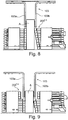
- FIG. 5 As can be seen, during a first 90 ° rotation of the insertion wheel 120, which fulfills the function of a delivery device against a subsequent operation, a hinged, rake-like guide 121 is pivoted against the book block A, so that the book block after the 90 ° rotation, on the back lying, not fanning and can not fall over.
- the rake-type guide 121 is coupled to a clamping unit 122, which clamps the book block in a lying on the back position short-term, and is kinematically designed so that the rake-like guide 121 in a buchdickenone Position can be transferred.
- the clamping unit 122 opens a little again, so that the book block A, following the gravity, gets the opportunity to align itself at its book block back against the stop surface 123 of the insertion wheel 120. Then the clamping unit 122 closes again, whereupon the book block is held firmly in a defined position.
- the four-part insertion wheel 120 now rotates for two cycles by 90 ° each and ensures the printed product generally in a now hanging position for further processing.
- first rake-like guide 121 and a second rake-type guide 124 operatively associated therewith are pivoted slightly away from the book block so that the pages of the book block hang vertically downwards solely by gravity while the book block is passing through the book block back the clamping unit 122 is held.
- this transport clamp 130 consists of two jaws 131, 132.
- the transport clamp operates so that the one jaw 131 performs no stroke, while the other jaw 132 makes the entire stroke.
- the two jaws 131, 132 drive two different offsets, which are related to whether the printed product is being transported in general or an empty run is being made.
- the stroke of the two clamping jaws 131, 132 of the transporting clip 130 is designed individually, ie that identical or different paths are taken until the final pressing position is completed.
- the transport clamp 130 can be moved horizontally by a linear motion device 133.
- a not shown in detail controlled drive moves the transport clamp 130 positionally accurate against a book block compliant transfer position. This takeover position is always dependent on the section to be cut off, which is to be made on the top or bottom of the book block. Then, in the transfer position closes the transport bracket 130 and thereby pinches the book block between its front and back surfaces over a large area. Only the back area and the section area of the book block to be cut off remain free. For this purpose, the description of FIG. 12 directed.
- the clamping unit 122 opens now and releases the book block back.
- the transport clamp 130 then moves horizontally and transports the book block in the first cutting position (see also FIG. 1 , Pos. 1) of a modular multi-cutting device.
- the two jaws 131, 132 can also be operated according to the following criteria: Each jaw is directly or indirectly in operative connection with a drive operating for the non-positive clamping action.
- the guided by the drives jaws have adjustable and / or predictively controlled lifting and adhesion profile on any Formataus Weggung of the submitted print product, so that the force applied by the jaws force detection of the printed product with respect to the center line is designed for symmetry or quasi-symmetry.
- the jaws perform at least during the operative phase for exerting the clamping action on the printed product a mutually tuned uniform, non-uniform or adaptive velocity profile. This operation can be provided for all operatively connected jaws, which are part of this application.
- the modular cutter 140 includes three cutting stations extending from a first station 141 at the cutting site 1 (see FIG. 1 ), a second station 142 at the cutting location 2 (see FIG. 1 ) and a third station 143 at the cutting location 3 (see FIG. 1 ) consist.
- a pressing plate 145 For the respective cutting operation of the book block by a pressing plate 145 and in addition with pressed a pressing bar 144, such that the book block by clamping bars 144 and the already mentioned press plates in the area between the transport clamp and the cutting edge during the cutting operation maximally clamped resp. is pressed.
- a knife 150b preferably moves in an oblique section against a per se fixed cutting bar.
- the remaining two cutting locations are operated by the knives 150a and 150c, which follow substantially the same pressing and cutting philosophy.
- the head portion of the book block is cut (see also FIG. 1 ).
- FIGS. 1 . 2, 3 engages during the cutting operation in vertical (Y-plane, see FIG. 1 ) as well as in the horizontal direction (X-plane, see FIG. 1 ) a movable, open first gripper 103, wherein in the vertical direction, the gripper is directed against the book block back.
- the first gripper 103 takes over the book block on the back and the transport clamp 130 opens. This transport clamp then moves to the takeover position for the next book block.
- the first gripper 103 transports the book block from this first cutting operation ( FIG. 1 , Pos. 1) vertically upwards (Y-plane) and moves by a superimposed, horizontal movement in the second cutting position ( FIG. 1 , Pos. 2).
- the moving distance of the first gripper 103 in the vertical direction is controlled by the machine control depending on the width of the cut book block, and also the moving distance of the gripper can be controlled individually in the horizontal direction with respect to the book block, as if a special gripping position is sought. For example, if the format and the sections to be cut in the respective book block an asymmetric or quasi-asymmetric or a one-sided focus-related clamping effect necessary.
- the book block In the second cutting position ( FIG. 1 , Pos. 2), the book block is formed by a plurality of pressure strips, the pressure bar to a battery ( Fig. 2, 3rd , Pos. 200), with which the book blocks are clamped between the front and the back.
- a battery Fig. 2, 3rd , Pos. 200
- FIG. 2 the pressure bar battery appears in the closed state while in FIG. 3 the pressure bar battery are shown in the open state.
- the first gripper 103 can let go of the book block and in its takeover position (cutting location 1, FIG. 1 ) for the next book block.
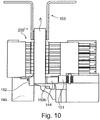
- FIG. 10 the ultimate force-related support of the book block A on the occasion of the cutting operation to ensure that the cut can be carried out with high quality by means of the knife 150b shown.
- the used pressure bars 200 1-n see the FIGS. 8, 9
- grip pressing bar which exercise the immediate contact force on the book block in the immediate cutting area.
- this force must be designed predominantly with respect to the pressing force exerted by the pressure bars, so that the cut carried out by knife 150b enables a cutting edge which is sharpened at right angles.
- the pressing device consists of a fixed stop 152 as part of a press plate 145 (see also FIG. 7 ) on one side of the book block and from an opposite movable press beam 144 on the other side, which is pressed against the book block by a press stud 151.
- the stopper 152 may also be made movable in a further embodiment to take into account the thickness and / or thickness consistency of the book block recessed from above, in other words, for the purpose that the leading edges of the inserted book block can not be pushed open. This dynamic adaptation of the stop 152 can be done by the already mentioned machine control.
- the press stud 151 for the press beam 144 may be driven by a motor, hydraulic, or pneumatic, thus exerting the predetermined pressing force on the book block.
- the second cutting operation front cut
- a second gripper 104 moves (see FIG. 1 ) in the position above the pressure bar battery and engages the book block in an analogous manner as was the case with the first gripper 103.
- the position of the second gripper 104, in which he clamps the book block is dependent on the cut book block height.
- the controller brings the second gripper 104 into the previously calculated gripping position, so that by the third cutting operation (see FIG. 1 , Pos. 3) on the book block, the correct book block height arises.
- the pressure bar battery 200 opens and the second gripper 104 moves the printed product through a vertical (out of the cutting position), then horizontal (feed to the next cutting position) and finally back to the cutting position for the vertical movement third circumcision (foot part) continues (see FIGS. 1 . 2 ).
- the loaded gripper in question still performs, as required, a lateral offset movement with respect to a clamping surface of the clamping device.
- the rotatable Entitiesvoroplasty (four-clamp system) 160 moves according to FIG. 11 and thus also the clip 161 with the book block orthogonal to the knife movement away from the knife.
- the rotatable four-clamp system 160 rotates 90 degrees during each stroke.
- FIG. 11 the position of the clip 161 in the cutting position 162 at which a movable jaw 163 is still open.
- Another bracket acts within the demand position 164. In this position, the book block A can be removed.
- the operation of the four-clamp system 160 ensures that the Book block A during the cutting process at the third cutting location 3 (see FIGS. 1 . 7 ) and the rotational movement of the four-clamp system is sustainably pressed between the movable jaw 163 and the fixed jaw 165.
- two states of the bracket 161 can be seen, namely a completely closed 166 and completely open 167 intermediate position. Specifically, one or the other variant can be considered within this quadrant, according to the prevailing space available during the rotation.
- sampling device may for example be a conveyor belt, which is equipped for the promotion of the book block with movable rollers.
- Other devices known in the art may also be provided.
- FIG. 12 shows the ultimate pressure of the book block by pressing bars 144 during the cutting operation. Such contact pressure corresponds to the effect of those under FIG. 10 has been described.
- the infeed direction is marked Pos. 170.
- FIG. 13 shows the interdependence of the various pressing elements (clamping devices) on the printed product, which, based on the cutting location 2, is exerted by the various clamping devices 103, 200, 144, wherein at this cutting location the one clamping device 200 consists of a pressure bar battery 200.
- the clamping forces of the various clamping devices in the diagram must also be understood only qualitatively.
- the clamping force of the gripper 103 which is provided for the transport 210 of the printed product from one cutting location to the next, is smaller in comparison with the cutting location-related clamping forces 200 and 144 per se, since this is only a force which is only for the secure clamping action of the printed product during transport must be sufficient.
- the clamping force of the pressure bars 200 1-n belonging to the pressure strip battery is then built up simultaneously or subsequently, so that the contact force of the gripper 103 immediately decreases 211 (acceptance point), as soon as the final clamping force of the Anpressangn is reached on the printed product.
- the extent to which the contact force of the gripper decreases to the printed product is set individually and also depends on the weight of the respective printed product.
- the final clamping force on the printed product which is important for the qualitative cutting quality, is then exerted by the already mentioned pressing bar 144, which assumes its position fully parallel to the plane of the cutting blade.
- the pressing bar 144 preferably deploys the greatest clamping force, which is variably and phase-shifted 212 (engaging plane) with respect to the other clamping devices, as shown by the parallel lines of interruption 212a, 212b (phase shift interval).
- the knife performs the cutting operation 213.
- the pressing bar 144 remains briefly in the cutting plane 215 until the contact force of the gripper has built up so far that a secure onward transport 214 of the printed product is ensured.
- the clamping forces of the remaining elements 144, 200 after a certain decrease curve 217 subsequent from, so that the further transport plane 216 is open again with the fully grasped by the gripper 103 printed product.
- this dynamic also applies to the second support 102 (see FIG. 1 ) belonging gripper 104 in operative connection with the respective clamping devices.
- FIG. 14 shows the configuration of a flush valve 125 (see also FIG. 3 ).
- This consists of a receiving plate acting from above 180, which carries printed product side brush body 181, 182, which exert pressure on the front over the printed product A protruding end turns 183, so that the back of the printed product coincides with the support surface within the insertion wheel 120. Since the turnup ends 184 lie in front of the same alignment plane, they can be seen better under the positions 185 and 186 (on the head or foot of the printed product A).
- Both brush bodies 181 and 182 each consist of two partial brush bodies 181a, 181b; 182a, 182b, which is angular stand each other, such that the respective turnup end is detected in a wedge shape and can be pressed parallel down accordingly, so that the turn-ends experienced no harmful bulge.
- FIG. 15 shows the configuration of another flush valve 126 (See also FIG. 3 ).
- This consists of one of the side (head or foot side) acting receiving plate 190 which carries printed product side brush body 191, 192, which exert pressure on the head or foot side over the printed product A projecting turnup ends 184, 185, so that the printed product A for the cutting operations are positioned accordingly.
- the overhanging ends are shown here in relation to the back part 193 of the printed product A.
- Both brush bodies 191 and 192 each consist of two partial brush bodies 191a, 191b; 192a, 192b, which are at an angle to each other, in such a way that the respective end of the envelope of the brush bodies detected in a wedge shape and the entire printed product body can be positioned laterally according to specification, so that the turn ends do not experience any harmful bulge.
- the three cutting stations 141, 142, 143 of the cutting device are arranged U-shaped with the open side of the U down against each other.
- the section of book block to be cut is operative in all three cutting operations in association with the pressing bars 144 (see FIG FIG. 7 , and particularly FIG. 10 ) against the inside of the U-shape.
- the book block height varies, depending on the envelope, the book is more or less in front of the book.
- the book blocks are made with a solid overhang of the envelope on one side and a variable overhang on the other side.
- the uncut book block or the uncut booklets are aligned at the foot or head edge and the processed back edge.
- the variable projections of the envelope in the book block height and the book width play no role.
- the three-cutter control product data For each book block to be cut or for each booklet to be cut, the three-cutter control product data must be known, from which the necessary movements of the transport organs can be expected, so that at the end a cut book is produced, which has the desired format dimensions.
- the book blocks are clocked fed to the three-knife trimmer.
- the three-cutter control is supplied with the information necessary to cut the book block to the correct dimension.
- data supplied with the book block can be supplemented with data from a database.
- Another possibility is to make the data known to the three-knife trimmer with an order of the book blocks before the book blocks are fed.
- the three-knife trimmer processes the next record in the given order with each book block being fed.
- the feeding of the book blocks must be done in the right order.
- a feature reader can be used in addition, which controls the order.
Claims (25)
- Procédé d'actionnement d'un appareil dévolu à l'exécution d'opérations de massicotage sur au moins un bord libre formaté d'au moins un produit imprimé, ledit appareil étant en liaison opérante avec un dispositif de présentation dédié aux produits imprimés, en vue de la première opération de massicotage, et avec un dispositif d'enlèvement qui est dédié auxdits produits imprimés et agit après la dernière opération de massicotage, chaque opération de massicotage affectant les bords étant exécutée par au moins un dispositif de sectionnement,
sachant que le produit imprimé (A) est transféré d'un premier site de coupe (1), auquel l'opération de massicotage est exécutée pour un premier bord formaté dudit produit imprimé, à un deuxième site de coupe (2) auquel ladite opération de massicotage s'effectue pour un deuxième bord formaté,
ledit produit imprimé étant transféré, après l'opération de massicotage exécutée audit deuxième site de coupe, à un troisième site de coupe (3) auquel ladite opération de massicotage s'effectue pour un troisième bord formaté, et
le transfert dudit produit imprimé, d'un site de coupe au site suivant, étant provoqué par l'intermédiaire d'au moins une unité de transport (101, 102, ...),
caractérisé par le fait
que l'unité de transport est pourvue d'au moins un moyen qui saisit le produit imprimé au niveau du dos afin de le convoyer, à l'état suspendu, d'un site de coupe jusqu'au site suivant. - Procédé selon la revendication 1, caractérisé par le fait que le produit imprimé, voué au massicotage, consiste en au moins un corps d'ouvrage unitaire, en des brochures individuelles ou en un certain nombre de brochures empilées.
- Procédé selon la revendication 1, caractérisé par le fait que les produits imprimés présentent, avant et/ou après les opérations de massicotage, des dimensions de format identiques ou variables moyennant des cotes en épaisseur identiques ou différentes.
- Procédé selon la revendication 1, caractérisé par le fait que le premier bord voué au massicotage concerne la tranche de tête, au premier site de coupe (1), que le deuxième bord voué au massicotage concerne la gouttière, au deuxième site de coupe (2), et que le troisième bord voué au massicotage concerne la tranche de queue du produit imprimé, au troisième site de coupe (3) ; ou par le fait que le premier bord voué au massicotage concerne la tranche de queue, audit premier site de coupe (1), que le deuxième bord voué au massicotage concerne la gouttière, audit deuxième site de coupe (2), et que le troisième bord voué au massicotage concerne la tranche de tête dudit produit imprimé, audit troisième site de coupe (3).
- Procédé selon la revendication 1, caractérisé par le fait que le dispositif de présentation, dévolu à l'orientation de la position d'un produit imprimé réalisé en tant que corps d'ouvrage (A), revêt la forme d'une roue d'insertion (120) en plusieurs parties qui est actionnée en conformité avec les critères suivants :a) au cours d'une première rotation de 90° de la roue d'insertion (120), un guide rabattable (121), du type râteau, accomplit un mouvement pivotant vers le corps d'ouvrage (A) de façon telle que ledit corps d'ouvrage (A) repose sur le dos (AR), à l'issue de la rotation de 90°, en étant ainsi protégé d'une ouverture en éventail et/ou d'un basculement ;b) le guide (121), du type râteau, est couplé à un groupe de coincement (122) par l'intermédiaire duquel le corps d'ouvrage (A) est brièvement coincé dans une position reposant sur le dos, ce groupe de coincement étant actionné cinématiquement de façon telle que ledit guide (121), du type râteau, soit transféré à un emplacement tributaire de l'épaisseur dudit corps d'ouvrage ;c) ledit groupe de coincement (122) s'ouvre ensuite de nouveau légèrement, de sorte que le dos (AR) dudit corps d'ouvrage s'oriente, sous l'effet de la gravité, vers une surface de butée (123) à l'intérieur de la roue d'insertion (120) ;d) ledit groupe de coincement (122) se ferme ensuite une fois encore, après quoi ledit corps d'ouvrage (A) présente un emplacement bien défini ;e) ladite roue d'insertion (120) poursuit alors sa rotation de deux cadences d'horloge, de 90° chacune, puis transfère ledit corps d'ouvrage (A) à une position désormais en suspension par rapport aux sites de coupe (1, 2, 3) ;f) au cours de ce mouvement rotatoire mentionné en dernier lieu, le premier guide (121) du type râteau, et un second guide (124) du type râteau relié de manière opérante, sont éloignés dudit bloc d'ouvrage par pivotement, et ledit bloc d'ouvrage (A) est alors retenu par ledit groupe de coincement (122), dans la région d'au moins une partie de son dos (AR), tandis que la partie dudit corps d'ouvrage (A), libérée par lesdits guides (121, 124), est suspendue verticalement vers le bas sous l'unique effet de la gravité.
- Procédé selon la revendication 1, caractérisé par le fait que le dispositif de présentation, dédié à des produits imprimés constitués d'au moins une brochure, revêt la forme d'une roue d'insertion (120) en plusieurs parties qui est actionnée en conformité avec les critères suivants :a) au cours d'une première rotation de 90° de la roue d'insertion (120), un guide rabattable (121), du type râteau, accomplit un mouvement pivotant vers la brochure de façon telle que ladite brochure repose sur le dos (AR), à l'issue de la rotation de 90°, en étant ainsi protégée d'une ouverture en éventail et/ou d'un basculement ;b) le guide (121), du type râteau, est couplé à un groupe de coincement (122) par l'intermédiaire duquel la brochure est brièvement coincée dans une position reposant sur le dos, ce groupe de coincement étant actionné cinématiquement de façon telle que ledit guide (121), du type râteau, soit transféré à un emplacement tributaire de l'épaisseur du corps d'ouvrage ;c) ledit groupe de coincement (122) s'ouvre ensuite de nouveau légèrement, de sorte que le dos de ladite brochure est orienté, sous l'effet de la gravité, vers une surface de butée (123) à l'intérieur de la roue d'insertion (120) ;d) ledit groupe de coincement (122) se ferme ensuite une fois encore, après quoi ladite brochure présente un emplacement bien défini ;e) ladite roue d'insertion (120) poursuit alors sa rotation de deux cadences d'horloge, de 90° chacune, puis transfère ladite brochure à une position désormais en suspension par rapport aux sites de coupe (1, 2, 3) ;f) au cours de ce mouvement rotatoire, le premier guide (121) du type râteau, et un second guide (124) du type râteau relié de manière opérante, sont éloignés de ladite brochure par pivotement, et ladite brochure est alors retenue par ledit groupe de coincement (122) dans la région d'au moins une partie de son dos (AR), tandis que la partie de ladite brochure, libérée par lesdits guides (121, 124), est suspendue verticalement vers le bas sous l'unique effet de la gravité.
- Procédé selon l'une des revendications 5 ou 6, caractérisé par le fait que des moyens supplémentaires, agissant par en haut (125) et/ou par le côté (126) à l'état ouvert du groupe de coincement (122), exercent une pression de courte durée sur des corps d'ouvrage ou sur des brochures, directement ou indirectement, en vue d'assurer l'emplacement extrême de ceux (celles)-ci par rapport à la surface de butée (123), ou un emplacement préétabli dans le sens horizontal.
- Procédé selon l'une ou plusieurs des revendications 1, 5 ou 6, caractérisé par le fait que le dispositif de présentation (120) est en liaison opérante, dans la région du premier site de coupe (1), avec un dispositif mobile de coincement (130) qui est équipé de platines de coincement (131, 132) et prélève le produit imprimé à partir dudit dispositif de présentation (120), après quoi ledit produit imprimé est dirigé vers la première opération de massicotage.
- Procédé selon la revendication 1, caractérisé par le fait que l'unité de transport est composée, pour l'essentiel, de deux supports (101, 102) dédiés aux produits imprimés et comportant chacun un organe de préhension (103, 104) ; par le fait que les organes de préhension saisissent, au niveau du dos (AR), le produit imprimé voué au massicotage ; par le fait que les deux supports/organes de préhension sont mutuellement en liaison opérante ; et par le fait que les mouvements translatoires mentionnés ci-après, assistés par commande, sont assignés auxdits supports/organes de préhension par rapport aux sites de coupe (1, 2, 3) :a) le premier organe de préhension (103) du premier support (101) prélève le produit imprimé après que la première opération de massicotage a été exécutée au premier site de coupe (1) ;b) ledit premier support se déplace ensuite, avec ce produit imprimé, vers le deuxième site de coupe (2) auquel il positionne ledit produit imprimé, en vue de l'exécution de la deuxième opération de massicotage, puis retourne à vide vers ledit premier site de coupe (1) auquel s'effectue le prélèvement réitéré d'un produit imprimé délivré après coup et déjà traité à ce site de coupe (1) ;c) dans l'entre-temps, le second support (102)/organe de préhension (104) prélève ledit produit imprimé audit deuxième site de coupe (2), immédiatement après une opération de massicotage achevée audit site, puis transfère ledit produit au troisième site de coupe (3) auquel la troisième opération de massicotage est exécutée ;d) le second support (102)/organe de préhension (104) retourne ensuite, à vide, vers ledit deuxième site de coupe (2) auquel se trouve un produit imprimé délivré après coup et massicoté une nouvelle fois, après quoi ledit second support (102)/organe de préhension (104) se déplace de nouveau, avec ce produit imprimé, vers ledit troisième site de coupe (3) auquel ladite troisième opération de massicotage est exécutée.
- Procédé selon l'une des revendications 1 ou 9, caractérisé par le fait que les organes de préhension (103, 104) sont équipés, aux extrémités, de mâchoires de coincement (103a, 103b ; 104a, 104b) agissant sur le produit imprimé ; et par le fait qu'au moins un organe de préhension chargé d'un produit imprimé accomplit dans la région d'au moins un site de coupe (1, 2, 3), avant et/ou après l'opération de massicotage, au moins un mouvement délibéré de décalage latéral par rapport à une surface de pression d'au moins un dispositif (103, 104, 130, 160/161, 200, 144) de coincement localisé.
- Procédé selon l'une ou plusieurs des revendications 1, 9 ou 10, caractérisé par le fait que le produit imprimé considéré est saisi, par les mâchoires de coincement de l'organe de préhension (103, 104) respectif, de manière symétrique, quasi symétrique, asymétrique ou maximalisée au centre de gravité dudit organe, et/ou en fonction des longueurs des bords devant être sectionnées.
- Procédé selon l'une ou plusieurs des revendications 1, 9 à 11, caractérisé par le fait qu'au moins un organe de préhension (103, 104) accomplit à au moins un site de coupe (1, 2, 3), avant et/ou après l'opération de massicotage considérée, un mouvement supplémentaire à effet de positionnement, dans au moins un plan, par rapport à une surface stationnaire de pression d'un dispositif de coincement.
- Procédé selon la revendication 1, caractérisé par le fait que le dispositif d'enlèvement (160) agit au troisième site de coupe (3) et est actionné en conformité avec les critères suivants :a) le dispositif d'enlèvement est actionné par l'intermédiaire d'une roue opérant en plusieurs parties ;b) ledit dispositif d'enlèvement est doté d'un dispositif de coincement (161) comprenant au moins une première mâchoire (163) et une seconde mâchoire (165), mâchoires au moyen desquelles un effet de coincement est exercé sur le produit imprimé (A) à l'occasion du processus de sectionnement ;c) à l'issue de l'opération de massicotage, ladite roue en plusieurs parties accomplit une rotation partielle par laquelle ledit produit imprimé est amené à l'emplacement d'évacuation.
- Procédé selon la revendication 1, caractérisé par le fait que l'un (150 a-c) des dispositifs de sectionnement est en liaison opérante, à chaque site de coupe (1, 2, 3), avec un dispositif respectif de coincement (130, 161, 200, 144) stationnaire ou quasi stationnaire ; par le fait que le dispositif de coincement applique au moins une force de pression au produit imprimé voué au massicotage ; par le fait que ledit dispositif de coincement comporte des surfaces de pression à action simple ou multiple, pouvant être commandées et faisant partie d'au moins une mâchoire de coincement ; et par le fait que ledit dispositif de coincement est coordonné avec la taille de format dudit produit imprimé ou est réglé au cours de l'actionnement, par des adaptations simultanées, sur les tailles de format respectives dudit produit imprimé.
- Procédé selon l'une ou plusieurs des revendications 1-14, caractérisé par le fait que des dispositifs de coincement (103, 104, 130, 160/161, 200, 144) développant des forces, mutuellement en liaison opérante, sont utilisés à chaque site de coupe (1, 2, 3) ; par le fait que la force de coincement de l'organe de préhension (103, 104), destiné au transport du produit imprimé d'un site de coupe (1, 2, 3) au site suivant, est plus petite comparativement à celles des premiers dispositifs de coincement (130, 160/161, 200) développant des forces ; et par le fait que ces premiers dispositifs de coincement (130, 160/161, 200) développant des forces appliquent, audit produit imprimé, une force de coincement inférieure à celle d'un second dispositif de coincement (144) affecté aux sites de coupe.
- Procédé selon la revendication 14 ou 15, caractérisé par le fait que les mâchoires de coincement d'au moins un dispositif de coincement accomplissent des mouvements relatifs en conformité avec les critères suivants :a) chaque mâchoire de coincement est, directement ou indirectement, en liaison opérante avec un entraînement exerçant activement l'effet de coincement par engagement positif, les mâchoires de coincement, guidées par les entraînements, appliquant des profils de course et d'engagement positif, réglables et/ou régulés en mode prédictif, à une quelconque démarcation de format du produit imprimé considéré ;b) le profil de mouvement par engagement positif dudit produit imprimé, accompli par l'intermédiaire desdites mâchoires de coincement, est détecté symétriquement ou quasi symétriquement par rapport à la ligne médiane dudit produit ;c) un profil de vitesse et/ou un profil de mouvement uniforme(s), non uniforme(s) ou adaptatif(s) est (sont) appliqué(s) avec coordination mutuelle par l'intermédiaire desdites mâchoires de coincement, au moins durant la phase active, en vue d'appliquer la force de coincement audit produit imprimé.
- Procédé selon la revendication 1, caractérisé par le fait que le produit imprimé est soumis à chaque poste de coupe, avant, pendant et après l'opération de massicotage, à l'action des forces de pression suivantes :a) une force de pression est appliquée, au produit imprimé, par l'intermédiaire des mâchoires de coincement (103a, 103b ; 104a, 104b) faisant partie de l'organe de préhension (103, 104), laquelle force de pression est conçue en vue du transport dudit produit imprimé d'un site de coupe au site suivant ;b) une force supplémentaire de pression est appliquée, audit produit imprimé, par l'intermédiaire d'un premier dispositif de coincement (130, 160/161, 200) opérant à chaque site de coupe, laquelle force de pression agit de manière stationnaire, sur ledit produit imprimé, dans la région du site de coupe respectif ;c) une force supplémentaire de pression, appliquée audit produit imprimé, est développée par un second dispositif de coincement (144) opérant à chaque site de coupe, laquelle force de pression agit directement dans la région du site de coupe respectif.
- Procédé selon la revendication 17, caractérisé par le fait qu'un premier dispositif de coincement (130) agit au premier site de coupe (1) ; par le fait qu'un premier dispositif de coincement (200) supplémentaire agit au deuxième site de coupe (2) ; par le fait qu'un premier dispositif de coincement (160/161) supplémentaire agit au troisième site de coupe (3) ; et par le fait que le second dispositif de coincement (144) agit en plus, respectivement, à chaque site de coupe (1, 2, 3).
- Procédé selon la revendication 17, caractérisé par le fait qu'un premier dispositif de coincement (200), actionné au moins au deuxième site de coupe (2), est constitué par des listels individuels de pression (2001-n) implantés verticalement ou quasi verticalement en aval ; et par le fait que les listels de pression placés sur l'un des côtés du produit imprimé sont positionnés rigidement, tandis que les listels de pression placés sur l'autre côté dudit produit imprimé accomplissent le mouvement de venue en applique par engagement positif.
- Procédé selon la revendication 17, caractérisé par le fait qu'un premier dispositif de coincement (200), actionné au moins au deuxième site de coupe (2), est constitué par des listels individuels de pression (2001-n) implantés verticalement ou quasi verticalement en aval ; et par le fait que les listels de pression placés des deux côtés du produit imprimé accomplissent un mouvement de venue en applique par engagement positif, uniforme ou quasi uniforme, dirigé vers ledit produit imprimé.
- Procédé selon la revendication 17, caractérisé par le fait qu'un premier dispositif de coincement (200), actionné au moins au deuxième site de coupe (2), est constitué par des listels individuels de pression (2001-n) implantés verticalement ou quasi verticalement en aval ; et par le fait que les listels de pression placés de part et d'autre du produit imprimé accomplissent des mouvements de venue en applique par engagement positif, leurs mouvements impliquant une symétrie ou une quasi-symétrie par rapport à la ligne médiane dudit produit imprimé.
- Procédé selon l'une ou plusieurs des revendications 17-21, caractérisé par le fait que, lors d'un mouvement subséquent de venue en applique des listels de pression (2001-n) vers le produit imprimé, l'effet de pression dudit mouvement débute par le premier listel de pression dans la région du dos dudit produit imprimé, pour se prolonger ensuite en continu par l'entrée en action des autres listels de pression, approximativement jusque dans le plan du bord voué au massicotage.
- Procédé selon la revendication 22, caractérisé par le fait que l'air, piégé entre les feuillets du produit imprimé, est expulsé continûment suite au pilotage subséquent des listels de pression à partir du dos dudit produit imprimé, jusqu'au bord voué au massicotage.
- Procédé selon l'une des revendications 1-23, caractérisé par le fait que l'opération de massicotage, ciblant les bords formatés individuels du produit imprimé, est exécutée par une opération de massicotage se déroulant individuellement au site de coupe (1, 2, 3) considéré.
- Procédé selon la revendication 24, caractérisé par le fait qu'au moins une opération de massicotage est conduite à l'aide d'une lame de sectionnement à action simple.
Applications Claiming Priority (1)
| Application Number | Priority Date | Filing Date | Title |
|---|---|---|---|
| CH5492015 | 2015-04-21 |
Publications (2)
| Publication Number | Publication Date |
|---|---|
| EP3085502A1 EP3085502A1 (fr) | 2016-10-26 |
| EP3085502B1 true EP3085502B1 (fr) | 2017-11-01 |
Family
ID=53008220
Family Applications (3)
| Application Number | Title | Priority Date | Filing Date |
|---|---|---|---|
| EP16152125.7A Active EP3085501B1 (fr) | 2015-04-21 | 2016-01-20 | Appareil de decoupage des rebords d'un produit imprime |
| EP16152142.2A Active EP3085502B1 (fr) | 2015-04-21 | 2016-01-20 | Procede de decoupage des rebords d'un produit imprime |
| EP16716455.7A Active EP3285978B1 (fr) | 2015-04-21 | 2016-03-29 | Dispositif pour effectuer des operations de coupe de bords de format ouvert d'un produit d'impression |
Family Applications Before (1)
| Application Number | Title | Priority Date | Filing Date |
|---|---|---|---|
| EP16152125.7A Active EP3085501B1 (fr) | 2015-04-21 | 2016-01-20 | Appareil de decoupage des rebords d'un produit imprime |
Family Applications After (1)
| Application Number | Title | Priority Date | Filing Date |
|---|---|---|---|
| EP16716455.7A Active EP3285978B1 (fr) | 2015-04-21 | 2016-03-29 | Dispositif pour effectuer des operations de coupe de bords de format ouvert d'un produit d'impression |
Country Status (5)
| Country | Link |
|---|---|
| US (3) | US10611041B2 (fr) |
| EP (3) | EP3085501B1 (fr) |
| JP (3) | JP6752026B2 (fr) |
| CN (3) | CN106064401B (fr) |
| WO (1) | WO2016168945A1 (fr) |
Families Citing this family (9)
| Publication number | Priority date | Publication date | Assignee | Title |
|---|---|---|---|---|
| EP3085501B1 (fr) | 2015-04-21 | 2017-12-20 | Müller Martini Holding AG | Appareil de decoupage des rebords d'un produit imprime |
| JP7107814B2 (ja) * | 2017-11-08 | 2022-07-27 | ミュラー・マルティニ・ホルディング・アクチエンゲゼルシヤフト | 印刷製品の綴じられていないフォーマットの余白の断裁動作を実行するための装置 |
| EP3599104A1 (fr) * | 2018-07-25 | 2020-01-29 | Müller Martini Holding AG | Installation de transport de produits imprimés d'une épaisseur similaire ou différente et leur procédé de transfert vers une réception |
| US11214078B2 (en) * | 2019-07-03 | 2022-01-04 | Primera Technology, Inc. | Label printer and cutter assembly |
| CN110802665B (zh) * | 2019-11-24 | 2020-09-01 | 浙江武义钓鱼实业有限公司 | 一种印刷纸张切割设备 |
| CN115648333A (zh) * | 2021-02-05 | 2023-01-31 | 兰溪合利机械有限公司 | 联本条分切设备 |
| CN113019972B (zh) * | 2021-03-11 | 2021-09-17 | 绍兴精翔机械制造有限公司 | 一种胶片金属探测及半幅自动剔除装置 |
| DE102021111394A1 (de) | 2021-05-03 | 2022-11-03 | Müller Martini Holding AG | Vorrichtung und Verfahren zum Pressen von Buchblocks |
| DE102022124182A1 (de) | 2022-09-21 | 2024-03-21 | Müller Martini Holding AG | Dynamischer Nutzenwechsel |
Family Cites Families (42)
| Publication number | Priority date | Publication date | Assignee | Title |
|---|---|---|---|---|
| GB834667A (en) * | 1955-11-05 | 1960-05-11 | Hans Biel | Improvements in and relating to a method and machine for trimming and cutting paper articles, sheet piles and the like, e.g. exercise books |
| DE1266275B (de) * | 1966-04-02 | 1968-04-18 | Guenther Schick Dipl Ing | Schneidemaschine zum vorzugsweise dreiseitigen Beschneiden von Buechern, Broschueren u. ae. mit ebenso vielen Messern |
| US3570350A (en) * | 1969-04-16 | 1971-03-16 | Comstock & Wescott | Cutter for book binding |
| US3722336A (en) * | 1971-02-10 | 1973-03-27 | North American Rockwell | Feed, transport and delivery mechanism for book trimmers and the like |
| US3822626A (en) * | 1973-06-01 | 1974-07-09 | Comstock & Wescott | Precision book cutting apparatus |
| CA1330033C (fr) * | 1988-10-31 | 1994-06-07 | Walter Reist | Methode et appareil de coupe de produits imprimes |
| DE59506928D1 (de) * | 1994-06-08 | 1999-11-04 | Ferag Ag | Einrichtung zum Beschneiden von Druckereierzeugnissen, wie z.B. Zeitungen, Zeitschriften und Broschüren, an wenigstens zwei Rändern |
| JP3793232B2 (ja) * | 1995-04-11 | 2006-07-05 | グラファ−ホルディング・アクチェンゲゼルシャフト | 印刷物ストリームの搬送方法及び装置 |
| DE19515705C2 (de) * | 1995-04-28 | 2003-04-10 | Kg Schneider Senator Verkaufs | Einrichtung zur Bearbeitung von Blattstapeln |
| US5950511A (en) * | 1995-05-02 | 1999-09-14 | Grapha-Holding Ag | Process and device for handling printed products |
| CN1082931C (zh) * | 1996-07-19 | 2002-04-17 | 费拉格有限公司 | 传送设备 |
| US6516695B2 (en) * | 1999-11-24 | 2003-02-11 | Heidelberger Druckmashcinen Ag | Device and method for trimming printed products |
| JP2001252890A (ja) * | 2000-03-08 | 2001-09-18 | Horizon International Inc | 三方断裁機 |
| US20030041712A1 (en) * | 2000-03-31 | 2003-03-06 | Masao Tsuruta | Apparatus for and method of manufacturing sheets |
| DE50011457D1 (de) * | 2000-08-07 | 2005-12-01 | Grapha Holding Ag | Einrichtung zum selbsttätigen Beschneiden der offenen Seitenkanten gebundener Druckprodukte |
| JP2002086395A (ja) * | 2000-09-13 | 2002-03-26 | Uht Corp | 穿孔または切断装置 |
| DE10101843B4 (de) * | 2001-01-17 | 2007-04-26 | Rathert, Horst, Dipl.-Ing. | Dreischneider insbesondere für Kleinauflagen |
| EP1234791B1 (fr) * | 2001-02-19 | 2004-10-06 | Grapha-Holding AG | Dispositif de prélèvement et de transmission de produits imprimés |
| ATE302154T1 (de) * | 2001-07-30 | 2005-09-15 | Ferag Ag | Verfahren und vorrichtung zum zusammenbringen und gemeinsamen weitertransportieren von flächigen gegenständen |
| DE10204296A1 (de) * | 2002-02-02 | 2003-08-14 | Kolbus Gmbh & Co Kg | Vorrichtung zum dreiseitigen Beschneiden von Druckprodukten |
| ITMI20030875A1 (it) * | 2003-04-30 | 2004-11-01 | Heidelberger Druckmasch Ag | Dispositivo per tagliare a misura blocchi di libri |
| DE10321370A1 (de) * | 2003-05-13 | 2004-12-02 | Kolbus Gmbh & Co. Kg | Vorrichtung zum Beladen einer Dreimesserschneidemaschine |
| EP1504860A1 (fr) | 2003-08-07 | 2005-02-09 | Müller Martini Holding AG | Méthode et dispositif d'ébarbage des bords latéraux de produits imprimés |
| ES2349126T3 (es) * | 2004-02-17 | 2010-12-28 | Muller Martini Holding Ag | Sistema para recortar el borde superior, el bordeinferior y el borde de apertura de un producto impreso. |
| ATE513662T1 (de) | 2004-10-18 | 2011-07-15 | Mueller Martini Holding Ag | Verfahren zum beschneiden mehrerer kanten eines druckproduktes |
| JP2006159385A (ja) * | 2004-12-10 | 2006-06-22 | Horizon International Inc | 厚み検出器付断裁機 |
| EP1683612B1 (fr) * | 2005-01-21 | 2016-08-03 | Ferag AG | Procédé et dispositif pour transporter des produits plats flexibles, et pour les découper au même temps |
| DE102005040799A1 (de) * | 2005-08-29 | 2007-03-01 | Heidelberger Druckmaschinen Ag | Vorrichtung zum dreiseitigen Beschnitt von Produkten |
| JP4924021B2 (ja) * | 2006-05-18 | 2012-04-25 | コニカミノルタビジネステクノロジーズ株式会社 | 断裁装置、後処理装置及び製本システム |
| AU2009208038B2 (en) * | 2008-01-24 | 2013-05-16 | Ferag Ag | Method and device for conveying planar products |
| EP2090441B1 (fr) * | 2008-02-18 | 2011-03-30 | Müller Martini Holding AG | Dispositif et procédé de fabrication de produits d'impression |
| EP2147759B1 (fr) * | 2008-07-24 | 2013-10-30 | Müller Martini Holding AG | Procédé et dispositif pour la coupe d'au moins un bord latéral de produits d'impression reliés |
| JP5318654B2 (ja) * | 2009-05-01 | 2013-10-16 | ニスカ株式会社 | 断裁装置及びこれを備えた製本装置 |
| US20110044786A1 (en) * | 2009-08-18 | 2011-02-24 | Perfect Systems, Llc | Apparatus for and method of clamping and trimming a perfect bound book |
| US8167293B2 (en) * | 2009-08-25 | 2012-05-01 | Lasermax Roll Systems, Inc. | System and method for inline cutting and stacking of sheets for formation of books |
| JP2012218114A (ja) | 2011-04-08 | 2012-11-12 | Yoshino Machinery Co Ltd | 断裁機 |
| DE102011105253B4 (de) | 2011-06-17 | 2015-06-11 | Dgr-Graphic Gmbh | Dreischneider |
| WO2013179380A1 (fr) * | 2012-05-29 | 2013-12-05 | ホリゾン・インターナショナル株式会社 | Appareil de coupe de reliure destiné à couper des bords à deux reprises |
| JP6458221B2 (ja) * | 2015-01-05 | 2019-01-30 | 芳野Ymマシナリー株式会社 | 冊子搬送装置、冊子搬送方法 |
| PL3253542T3 (pl) * | 2015-02-03 | 2019-04-30 | Mtorres Tissue S R L | Urządzenie do mocowania beli podczas jej cięcia oraz piła maszynowa zawierająca to urządzenie |
| EP3085501B1 (fr) * | 2015-04-21 | 2017-12-20 | Müller Martini Holding AG | Appareil de decoupage des rebords d'un produit imprime |
| DK3115325T3 (da) * | 2015-07-06 | 2018-11-12 | Mueller Martini Holding Ag | Indretning og fremgangsmåde til dannelse af en stabel af reklamesamlinger |
-
2016
- 2016-01-20 EP EP16152125.7A patent/EP3085501B1/fr active Active
- 2016-01-20 EP EP16152142.2A patent/EP3085502B1/fr active Active
- 2016-02-19 JP JP2016029692A patent/JP6752026B2/ja active Active
- 2016-02-19 JP JP2016029690A patent/JP6718695B2/ja active Active
- 2016-02-29 CN CN201610110172.3A patent/CN106064401B/zh active Active
- 2016-02-29 CN CN201610121336.2A patent/CN106064402B/zh active Active
- 2016-03-29 WO PCT/CH2016/000053 patent/WO2016168945A1/fr unknown
- 2016-03-29 CN CN201680023049.6A patent/CN107848131B/zh active Active
- 2016-03-29 EP EP16716455.7A patent/EP3285978B1/fr active Active
- 2016-03-29 JP JP2017554825A patent/JP6752225B2/ja active Active
- 2016-04-20 US US15/133,238 patent/US10611041B2/en active Active
- 2016-04-20 US US15/133,239 patent/US10639809B2/en active Active
-
2017
- 2017-10-20 US US15/788,818 patent/US10059014B2/en active Active
Non-Patent Citations (1)
| Title |
|---|
| None * |
Also Published As
| Publication number | Publication date |
|---|---|
| EP3085501B1 (fr) | 2017-12-20 |
| JP6752225B2 (ja) | 2020-09-09 |
| CN107848131B (zh) | 2020-06-19 |
| US10059014B2 (en) | 2018-08-28 |
| US20160311126A1 (en) | 2016-10-27 |
| JP2018513026A (ja) | 2018-05-24 |
| EP3085501A1 (fr) | 2016-10-26 |
| JP6718695B2 (ja) | 2020-07-08 |
| JP2016203364A (ja) | 2016-12-08 |
| CN107848131A (zh) | 2018-03-27 |
| EP3085502A1 (fr) | 2016-10-26 |
| JP2016203363A (ja) | 2016-12-08 |
| US10611041B2 (en) | 2020-04-07 |
| EP3285978A1 (fr) | 2018-02-28 |
| CN106064401B (zh) | 2020-07-14 |
| CN106064402A (zh) | 2016-11-02 |
| JP6752026B2 (ja) | 2020-09-09 |
| WO2016168945A1 (fr) | 2016-10-27 |
| CN106064401A (zh) | 2016-11-02 |
| EP3285978B1 (fr) | 2019-03-06 |
| US20180056537A1 (en) | 2018-03-01 |
| CN106064402B (zh) | 2020-10-23 |
| US20160311125A1 (en) | 2016-10-27 |
| US10639809B2 (en) | 2020-05-05 |
Similar Documents
| Publication | Publication Date | Title |
|---|---|---|
| EP3085502B1 (fr) | Procede de decoupage des rebords d'un produit imprime | |
| EP2457738B1 (fr) | Procédé de reliure par collage d'un bloc de livre avec feuille de garde | |
| EP2508353A2 (fr) | Machine destinée à la fabrication de livres, notamment livres photo et/ou livres illustrés | |
| EP2377688B1 (fr) | Dispositif de fabrication de produits à reliure adhésive | |
| EP1690696A1 (fr) | Dispositif et procédé pour l'endossage mécanique des signatures | |
| EP0675005A1 (fr) | Dispositif pour la reliure adhésive de produits imprimés | |
| EP2397339B2 (fr) | Procédé et dispositif destinés à la fabrication de couvertures de livre | |
| EP3482892A2 (fr) | Dispositif pour l'exécution d'opérations de coupe de bords de format ouverts d'un produit imprimé | |
| DE3934217A1 (de) | Vorrichtung zum anbringen von verstaerkungen an registereinlagen | |
| DE10039908A1 (de) | Verfahren und Vorrichtung zum maschinellen Heften von mehrteiligen Druckereiprodukten mittels Drahtklammern | |
| EP3406456A1 (fr) | Encolleuse | |
| EP1683612B1 (fr) | Procédé et dispositif pour transporter des produits plats flexibles, et pour les découper au même temps | |
| DE10124068A1 (de) | Vorrichtung und Verfahren zum automatischen Positionieren und Beschneiden von Schneidgut aus Papierwerkstoffen oder papierwerkstoffähnlichen, stapelbaren Materialien | |
| DE102020108423A1 (de) | Einrichtung und Verfahren für die Durchführung von Schneidoperationen im Bereich der offenen Formatkanten von Druckprodukten | |
| EP2323938B1 (fr) | Dispositif de collecte et de transport d'empilements formés de couches de feuilles | |
| DE2220567A1 (de) | Verfahren und vorrichtung zum buchbinden | |
| DE3444576A1 (de) | Verfahren und vorrichtung zur herstellung von buechern, insbesondere taschenbuechern, broschueren und zeitschriften | |
| DE10014360B4 (de) | Vorrichtung zum Vorderbeschnitt eines blattförmigen Druckerzeugnisses | |
| EP1182052B1 (fr) | Méthode et dispositif pour le traitement des produits imprimés en forme de feuille | |
| EP2508351A2 (fr) | Dispositif destiné à la fabrication d'un bloc de livre | |
| DE261144C (fr) | ||
| DE10001946A1 (de) | Vorrichtung zur buchbinderischen Verarbeitung von Papierstapeln | |
| EP4034390A1 (fr) | Dispositif et procédé de fabrication automatique de couvertures de reliures de livres et/ou de couvertures de boîtes | |
| DE267552C (fr) | ||
| AT23895B (de) | Maschine zur Herstellung von gefütterten und einfachen Papiersäcken mit Kreuzboden von quadratischer oder oblonger Form. |
Legal Events
| Date | Code | Title | Description |
|---|---|---|---|
| PUAI | Public reference made under article 153(3) epc to a published international application that has entered the european phase |
Free format text: ORIGINAL CODE: 0009012 |
|
| AK | Designated contracting states |
Kind code of ref document: A1 Designated state(s): AL AT BE BG CH CY CZ DE DK EE ES FI FR GB GR HR HU IE IS IT LI LT LU LV MC MK MT NL NO PL PT RO RS SE SI SK SM TR |
|
| AX | Request for extension of the european patent |
Extension state: BA ME |
|
| 17P | Request for examination filed |
Effective date: 20170221 |
|
| GRAP | Despatch of communication of intention to grant a patent |
Free format text: ORIGINAL CODE: EPIDOSNIGR1 |
|
| RBV | Designated contracting states (corrected) |
Designated state(s): AL AT BE BG CH CY CZ DE DK EE ES FI FR GB GR HR HU IE IS IT LI LT LU LV MC MK MT NL NO PL PT RO RS SE SI SK SM TR |
|
| INTG | Intention to grant announced |
Effective date: 20170330 |
|
| GRAS | Grant fee paid |
Free format text: ORIGINAL CODE: EPIDOSNIGR3 |
|
| GRAJ | Information related to disapproval of communication of intention to grant by the applicant or resumption of examination proceedings by the epo deleted |
Free format text: ORIGINAL CODE: EPIDOSDIGR1 |
|
| GRAL | Information related to payment of fee for publishing/printing deleted |
Free format text: ORIGINAL CODE: EPIDOSDIGR3 |
|
| INTC | Intention to grant announced (deleted) | ||
| GRAP | Despatch of communication of intention to grant a patent |
Free format text: ORIGINAL CODE: EPIDOSNIGR1 |
|
| INTG | Intention to grant announced |
Effective date: 20170831 |
|
| GRAA | (expected) grant |
Free format text: ORIGINAL CODE: 0009210 |
|
| AK | Designated contracting states |
Kind code of ref document: B1 Designated state(s): AL AT BE BG CH CY CZ DE DK EE ES FI FR GB GR HR HU IE IS IT LI LT LU LV MC MK MT NL NO PL PT RO RS SE SI SK SM TR |
|
| REG | Reference to a national code |
Ref country code: GB Ref legal event code: FG4D Free format text: NOT ENGLISH |
|
| REG | Reference to a national code |
Ref country code: CH Ref legal event code: EP Ref country code: AT Ref legal event code: REF Ref document number: 941605 Country of ref document: AT Kind code of ref document: T Effective date: 20171115 |
|
| REG | Reference to a national code |
Ref country code: IE Ref legal event code: FG4D Free format text: LANGUAGE OF EP DOCUMENT: GERMAN |
|
| REG | Reference to a national code |
Ref country code: DE Ref legal event code: R096 Ref document number: 502016000236 Country of ref document: DE |
|
| REG | Reference to a national code |
Ref country code: FR Ref legal event code: PLFP Year of fee payment: 3 |
|
| REG | Reference to a national code |
Ref country code: NL Ref legal event code: MP Effective date: 20171101 |
|
| REG | Reference to a national code |
Ref country code: LT Ref legal event code: MG4D |
|
| PG25 | Lapsed in a contracting state [announced via postgrant information from national office to epo] |
Ref country code: SE Free format text: LAPSE BECAUSE OF FAILURE TO SUBMIT A TRANSLATION OF THE DESCRIPTION OR TO PAY THE FEE WITHIN THE PRESCRIBED TIME-LIMIT Effective date: 20171101 Ref country code: NO Free format text: LAPSE BECAUSE OF FAILURE TO SUBMIT A TRANSLATION OF THE DESCRIPTION OR TO PAY THE FEE WITHIN THE PRESCRIBED TIME-LIMIT Effective date: 20180201 Ref country code: FI Free format text: LAPSE BECAUSE OF FAILURE TO SUBMIT A TRANSLATION OF THE DESCRIPTION OR TO PAY THE FEE WITHIN THE PRESCRIBED TIME-LIMIT Effective date: 20171101 Ref country code: ES Free format text: LAPSE BECAUSE OF FAILURE TO SUBMIT A TRANSLATION OF THE DESCRIPTION OR TO PAY THE FEE WITHIN THE PRESCRIBED TIME-LIMIT Effective date: 20171101 Ref country code: NL Free format text: LAPSE BECAUSE OF FAILURE TO SUBMIT A TRANSLATION OF THE DESCRIPTION OR TO PAY THE FEE WITHIN THE PRESCRIBED TIME-LIMIT Effective date: 20171101 Ref country code: LT Free format text: LAPSE BECAUSE OF FAILURE TO SUBMIT A TRANSLATION OF THE DESCRIPTION OR TO PAY THE FEE WITHIN THE PRESCRIBED TIME-LIMIT Effective date: 20171101 |
|
| PG25 | Lapsed in a contracting state [announced via postgrant information from national office to epo] |
Ref country code: RS Free format text: LAPSE BECAUSE OF FAILURE TO SUBMIT A TRANSLATION OF THE DESCRIPTION OR TO PAY THE FEE WITHIN THE PRESCRIBED TIME-LIMIT Effective date: 20171101 Ref country code: IS Free format text: LAPSE BECAUSE OF FAILURE TO SUBMIT A TRANSLATION OF THE DESCRIPTION OR TO PAY THE FEE WITHIN THE PRESCRIBED TIME-LIMIT Effective date: 20180301 Ref country code: HR Free format text: LAPSE BECAUSE OF FAILURE TO SUBMIT A TRANSLATION OF THE DESCRIPTION OR TO PAY THE FEE WITHIN THE PRESCRIBED TIME-LIMIT Effective date: 20171101 Ref country code: BG Free format text: LAPSE BECAUSE OF FAILURE TO SUBMIT A TRANSLATION OF THE DESCRIPTION OR TO PAY THE FEE WITHIN THE PRESCRIBED TIME-LIMIT Effective date: 20180201 Ref country code: LV Free format text: LAPSE BECAUSE OF FAILURE TO SUBMIT A TRANSLATION OF THE DESCRIPTION OR TO PAY THE FEE WITHIN THE PRESCRIBED TIME-LIMIT Effective date: 20171101 Ref country code: GR Free format text: LAPSE BECAUSE OF FAILURE TO SUBMIT A TRANSLATION OF THE DESCRIPTION OR TO PAY THE FEE WITHIN THE PRESCRIBED TIME-LIMIT Effective date: 20180202 |
|
| PG25 | Lapsed in a contracting state [announced via postgrant information from national office to epo] |
Ref country code: CZ Free format text: LAPSE BECAUSE OF FAILURE TO SUBMIT A TRANSLATION OF THE DESCRIPTION OR TO PAY THE FEE WITHIN THE PRESCRIBED TIME-LIMIT Effective date: 20171101 Ref country code: SK Free format text: LAPSE BECAUSE OF FAILURE TO SUBMIT A TRANSLATION OF THE DESCRIPTION OR TO PAY THE FEE WITHIN THE PRESCRIBED TIME-LIMIT Effective date: 20171101 Ref country code: EE Free format text: LAPSE BECAUSE OF FAILURE TO SUBMIT A TRANSLATION OF THE DESCRIPTION OR TO PAY THE FEE WITHIN THE PRESCRIBED TIME-LIMIT Effective date: 20171101 Ref country code: DK Free format text: LAPSE BECAUSE OF FAILURE TO SUBMIT A TRANSLATION OF THE DESCRIPTION OR TO PAY THE FEE WITHIN THE PRESCRIBED TIME-LIMIT Effective date: 20171101 Ref country code: CY Free format text: LAPSE BECAUSE OF FAILURE TO SUBMIT A TRANSLATION OF THE DESCRIPTION OR TO PAY THE FEE WITHIN THE PRESCRIBED TIME-LIMIT Effective date: 20171101 |
|
| REG | Reference to a national code |
Ref country code: DE Ref legal event code: R097 Ref document number: 502016000236 Country of ref document: DE |
|
| PG25 | Lapsed in a contracting state [announced via postgrant information from national office to epo] |
Ref country code: RO Free format text: LAPSE BECAUSE OF FAILURE TO SUBMIT A TRANSLATION OF THE DESCRIPTION OR TO PAY THE FEE WITHIN THE PRESCRIBED TIME-LIMIT Effective date: 20171101 Ref country code: SM Free format text: LAPSE BECAUSE OF FAILURE TO SUBMIT A TRANSLATION OF THE DESCRIPTION OR TO PAY THE FEE WITHIN THE PRESCRIBED TIME-LIMIT Effective date: 20171101 Ref country code: PL Free format text: LAPSE BECAUSE OF FAILURE TO SUBMIT A TRANSLATION OF THE DESCRIPTION OR TO PAY THE FEE WITHIN THE PRESCRIBED TIME-LIMIT Effective date: 20171101 |
|
| PLBE | No opposition filed within time limit |
Free format text: ORIGINAL CODE: 0009261 |
|
| STAA | Information on the status of an ep patent application or granted ep patent |
Free format text: STATUS: NO OPPOSITION FILED WITHIN TIME LIMIT |
|
| PG25 | Lapsed in a contracting state [announced via postgrant information from national office to epo] |
Ref country code: MT Free format text: LAPSE BECAUSE OF FAILURE TO SUBMIT A TRANSLATION OF THE DESCRIPTION OR TO PAY THE FEE WITHIN THE PRESCRIBED TIME-LIMIT Effective date: 20171101 |
|
| 26N | No opposition filed |
Effective date: 20180802 |
|
| PG25 | Lapsed in a contracting state [announced via postgrant information from national office to epo] |
Ref country code: LU Free format text: LAPSE BECAUSE OF NON-PAYMENT OF DUE FEES Effective date: 20180120 |
|
| REG | Reference to a national code |
Ref country code: IE Ref legal event code: MM4A |
|
| REG | Reference to a national code |
Ref country code: BE Ref legal event code: MM Effective date: 20180131 |
|
| PG25 | Lapsed in a contracting state [announced via postgrant information from national office to epo] |
Ref country code: SI Free format text: LAPSE BECAUSE OF FAILURE TO SUBMIT A TRANSLATION OF THE DESCRIPTION OR TO PAY THE FEE WITHIN THE PRESCRIBED TIME-LIMIT Effective date: 20171101 Ref country code: BE Free format text: LAPSE BECAUSE OF NON-PAYMENT OF DUE FEES Effective date: 20180131 |
|
| PG25 | Lapsed in a contracting state [announced via postgrant information from national office to epo] |
Ref country code: IE Free format text: LAPSE BECAUSE OF NON-PAYMENT OF DUE FEES Effective date: 20180120 |
|
| PG25 | Lapsed in a contracting state [announced via postgrant information from national office to epo] |
Ref country code: MC Free format text: LAPSE BECAUSE OF FAILURE TO SUBMIT A TRANSLATION OF THE DESCRIPTION OR TO PAY THE FEE WITHIN THE PRESCRIBED TIME-LIMIT Effective date: 20171101 |
|
| PG25 | Lapsed in a contracting state [announced via postgrant information from national office to epo] |
Ref country code: TR Free format text: LAPSE BECAUSE OF FAILURE TO SUBMIT A TRANSLATION OF THE DESCRIPTION OR TO PAY THE FEE WITHIN THE PRESCRIBED TIME-LIMIT Effective date: 20171101 |
|
| PG25 | Lapsed in a contracting state [announced via postgrant information from national office to epo] |
Ref country code: PT Free format text: LAPSE BECAUSE OF FAILURE TO SUBMIT A TRANSLATION OF THE DESCRIPTION OR TO PAY THE FEE WITHIN THE PRESCRIBED TIME-LIMIT Effective date: 20171101 |
|
| PG25 | Lapsed in a contracting state [announced via postgrant information from national office to epo] |
Ref country code: MK Free format text: LAPSE BECAUSE OF NON-PAYMENT OF DUE FEES Effective date: 20171101 Ref country code: HU Free format text: LAPSE BECAUSE OF FAILURE TO SUBMIT A TRANSLATION OF THE DESCRIPTION OR TO PAY THE FEE WITHIN THE PRESCRIBED TIME-LIMIT; INVALID AB INITIO Effective date: 20160120 |
|
| PG25 | Lapsed in a contracting state [announced via postgrant information from national office to epo] |
Ref country code: AL Free format text: LAPSE BECAUSE OF FAILURE TO SUBMIT A TRANSLATION OF THE DESCRIPTION OR TO PAY THE FEE WITHIN THE PRESCRIBED TIME-LIMIT Effective date: 20171101 |
|
| GBPC | Gb: european patent ceased through non-payment of renewal fee |
Effective date: 20200120 |
|
| PG25 | Lapsed in a contracting state [announced via postgrant information from national office to epo] |
Ref country code: GB Free format text: LAPSE BECAUSE OF NON-PAYMENT OF DUE FEES Effective date: 20200120 |
|
| REG | Reference to a national code |
Ref country code: AT Ref legal event code: MM01 Ref document number: 941605 Country of ref document: AT Kind code of ref document: T Effective date: 20210120 |
|
| PG25 | Lapsed in a contracting state [announced via postgrant information from national office to epo] |
Ref country code: AT Free format text: LAPSE BECAUSE OF NON-PAYMENT OF DUE FEES Effective date: 20210120 |
|
| PGFP | Annual fee paid to national office [announced via postgrant information from national office to epo] |
Ref country code: CH Payment date: 20220121 Year of fee payment: 7 |
|
| PGFP | Annual fee paid to national office [announced via postgrant information from national office to epo] |
Ref country code: FR Payment date: 20220124 Year of fee payment: 7 |
|
| PGFP | Annual fee paid to national office [announced via postgrant information from national office to epo] |
Ref country code: IT Payment date: 20230131 Year of fee payment: 8 Ref country code: DE Payment date: 20230126 Year of fee payment: 8 |
|
| REG | Reference to a national code |
Ref country code: CH Ref legal event code: PL |
|
| PG25 | Lapsed in a contracting state [announced via postgrant information from national office to epo] |
Ref country code: LI Free format text: LAPSE BECAUSE OF NON-PAYMENT OF DUE FEES Effective date: 20230131 Ref country code: CH Free format text: LAPSE BECAUSE OF NON-PAYMENT OF DUE FEES Effective date: 20230131 |
|
| PG25 | Lapsed in a contracting state [announced via postgrant information from national office to epo] |
Ref country code: FR Free format text: LAPSE BECAUSE OF NON-PAYMENT OF DUE FEES Effective date: 20230131 |