EP2508351A2 - Dispositif destiné à la fabrication d'un bloc de livre - Google Patents
Dispositif destiné à la fabrication d'un bloc de livre Download PDFInfo
- Publication number
- EP2508351A2 EP2508351A2 EP12162044A EP12162044A EP2508351A2 EP 2508351 A2 EP2508351 A2 EP 2508351A2 EP 12162044 A EP12162044 A EP 12162044A EP 12162044 A EP12162044 A EP 12162044A EP 2508351 A2 EP2508351 A2 EP 2508351A2
- Authority
- EP
- European Patent Office
- Prior art keywords
- stack
- sheet
- folded
- station
- outer side
- Prior art date
- Legal status (The legal status is an assumption and is not a legal conclusion. Google has not performed a legal analysis and makes no representation as to the accuracy of the status listed.)
- Withdrawn
Links
Images


Classifications
-
- B—PERFORMING OPERATIONS; TRANSPORTING
- B42—BOOKBINDING; ALBUMS; FILES; SPECIAL PRINTED MATTER
- B42C—BOOKBINDING
- B42C19/00—Multi-step processes for making books
- B42C19/02—Multi-step processes for making books starting with single sheets
Definitions
- the invention relates to a device for producing a book block, which consists of layers of folded and folded along a folding edge fold line, with a stacking station, in a stacking area on its first outer side provided with glue, folded sheets into a stack for forming a book block and has a stacking area limiting means for holding the stack and a pressing means having at least one pressing means which is adapted to generate pressure on the top of the stack to press the stack against the abutment means.
- Such a device is used in particular for laminating folded or folded sheets for the purpose of producing a photobook block and is normally part of a system for producing photobook blocks or the like.
- a material web unwound from a roll is printed in a printing station, for example; Alternatively or additionally, it is also conceivable that the wound on the roll material web has been previously printed and / or coated. From the web are then separated by cross-cutting printed sheets. The sheets are folded along a folding or folding line, so that the folding or folding line a folding or folding edge forms.
- the folded sheets are provided with adhesive before being stacked in a stacking station by connecting two adjacent sides of the folded sheets together through the adhesive to form a common side.
- the overlapping folding edges of the sheets in the stack together form the spine of the book block formed from the stack. Subsequently, the finished stack is removed from the stack formation area of the stack forming station and transported to a subsequent station for further processing, in particular for the completion of the book block.
- the DE 41 41 767 A1 describes a method and arrangement for making books and booklets that consist of folded layers of interconnected sheets with the top and bottom sheets of the folded layers adhered to rigid covers.
- multi-use layers are successively conveyed and their sheets connected in at least one connection station by a mechanical bond and then folded or folded in a folding station.
- the top and bottom sheets of folded or folded sheets are fed with blankets which are glued to the sheets.
- On the backs of the layers limzelstMail be glued in a Klalzelstation.
- the multi-use folded laminated and provided with DesilzelstMail layers are cut in a cutting station to individual use in book size.
- the invention is an object of the invention to provide a device of the type mentioned, which is suitable for automatic production with high performance and accuracy, and in particular allows an accurate alignment of the sheet within the stack to be formed.
- a device for producing a book block which consists of layers of interconnected and folded along a folding edge fold line with a stacking station, in a stacking area on its first outer side provided with glue, folded sheets into a stack for forming a book block and comprising a stacking area limiting means for holding the stack and a pressing means having at least one pressing means, which is designed to generate pressure on the top of the stack to press the stack against the abutment means, characterized in that the pressing means is simultaneously movable along the top of the stack through the stacking area during the generation of pressure on the top of the stack, and the stacking station comprises an aligning means having a folded sheet with its adhesive with adhesive aligning the first outer side to the abutment means and thus to a sheet or stack already held on the abutment means, wherein the pressing means is further configured such that the pressing means generates pressure on the second outer side of each folded sheet after this sheet from the aligning means with its adhesive provided first outside to the attachment means and thus has been aligned to
- a special feature of the present invention is thus to form and arrange the pressing means so that it not only generates pressure on the top of the stack, but also moves along the top of the stack through the stack formation area meanwhile.
- the new sheet with its adhesive provided with the first outer side to the investment means and thus to an already held on the investment means sheet or stack using an inventively provided alignment aligned accordingly. Due to the inventive movement of the pressing means on the top of the stack along a particularly high and uniform adhesive effect is achieved for a secure connection of two adjacent layers of the folded sheet and thus for a secure stack formation.
- the solution according to the invention leads to a fully automatic, safe and efficient lamination of folded sheets in order to form a book block with very high quality.
- the at least one pressing means is preferably designed as a roller which is unrolled on the surface of the upper side of the stack.
- a pressing, pressing or laminating roller is used as the pressing means, which drives the respective uppermost folded sheet against or onto the previously formed sheet stack and presses it with it.
- a plurality of pressing means is provided, of which a pressing means generates pressure on the second outer side of each one of the aligning device aligned new sheet.
- a pressing means can be provided for each new sheet, which is assigned to this sheet.
- the pressing means are moved successively through the stack formation area.
- the pressing means may preferably be movably mounted along a closed guideway extending through the stack forming region.
- the pressing means operate in circulation mode, which is advantageous for a continuous process and in particular for fully automatic operation.
- the pressure means should be equidistant in the previously described development along the guideway be arranged to each other, so that the distance between each two adjacent pressing means is substantially constant.
- a further preferred embodiment of the invention is characterized in that the abutment means has a stacking area bounding, substantially vertical abutment plane on which the stack can be applied, and the alignment is formed such that it adjacent to the abutment means in a Spaces in which the arc is aligned at an angle, preferably at an angle of at least 45 ° and at most 85 ° to the horizontal.
- the alignment device preferably has a lower stop which is adjacent to the abutment means and also delimits the stack formation area and is designed such that it brings a folded sheet with its folded edge into abutment with the lower stop.
- the movement sequence according to the two preferred embodiments of the invention given above is particularly advantageous for an automatic process and a continuous operation.
- the fact that the sheets are spent in particular from a horizontal orientation in a downwardly inclined or substantially even vertical position it is possible to support the sheet on its underside and to guide so that without problems whose top first provided with adhesive and thus glued and then aligned to the investment means and thus to the stack already formed there.
- the pressing means is moved by the stack formation area in the upward direction.
- the advantage of this development is in particular that both already by the movement of the pressing means on the newly delivered and aligned sheet along with simultaneous pressurization in the direction of the stack previously formed at the investment means already folded layers of this sheet on the one hand and on the other hand come to rest flat on the previously formed stack.
- a further preferred embodiment of the invention is characterized in that the pressing device has an additional pressing element, which is arranged substantially stationary adjacent to the abutment means and is formed, pressure on the second outer side of each folded sheet in a folding edge adjacent or adjacent to the folded edge To produce edge portion to press this edge portion of the sheet in the direction of the abutment means and thus against the stack.
- the additional pressing element is arranged adjacent to the lower stop.
- the additional pressure element between a working position in which it creates pressure on the second outer side of each folded sheet in a folding edge adjacent or adjacent to the fold edge edge portion and a rest position engageable, preferably pivotable, arranged and thereby preferably plate-shaped and with its lower Section to be mounted pivotably about a substantially horizontal pivot axis.
- the additional pressure element advantageously provides for an additional stationary fixation of the respectively newly supplied sheet to the previously formed stack, which has a positive effect on the quality of the stack formation.
- the holding means holding the stack is adjustable by an adjusting device such that during the formation of the stack whose upper side remains substantially stationary in substantially the same, preferably approximately vertical, plane.
- the sequence in the alignment and arrangement of the respectively newly supplied sheet on the top of the stack already formed on the investment means can be simplified, since a substantially stationary and spatially invariable position is available for the alignment and arrangement of the sheet. This applies in particular to the case that the pressing means is guided along a fixed path or a fixed path through the stack formation area.
- a further preferred embodiment with a conveying device which is provided for removing a, preferably finished, stack from the stack formation area, is characterized in that the conveying device has a pliers arranged adjacent to the abutment means, preferably below the abutment means, which are aligned and formed in this way is that their jaws can be brought into clamping engagement with an adjacent to the folding edges of the sheet or adjacent to the folding edges of the sheet edge portion of the stack.
- an adhesive applicator station is used to apply adhesive to the first outer side of the folded sheets, the first outer side of the sheets being the top, and a conveyor is provided which already folds folded sheets with their folded edge about horizontal in orientation Substantially one after the other in the adhesive application station promotes. Thus, the top of the sheet is glued when they are approximately in a horizontal orientation and thereby passed through the adhesive application station.
- a transfer device is additionally provided in this embodiment, which connects the adhesive application station to the downstream stacking station and has a conveying means on which the folded sheet provided with adhesive rest with its second outer side forming the lower side and with its folded edge substantially successively from the Adhesive application station are transferred to the stack forming station.
- the conveying means is designed in such a way that it removes the adhesive-provided folded sheets from the substantially horizontal alignment in the region of the adhesive application station transferred to the above-mentioned downwardly inclined position in the alignment device.
- it is particularly advantageous to use as conveyor an endlessly circulating, preferably designed as a suction belt, conveyor belt whose upper run, which carries the provided on its upper side with adhesive folded sheet on the underside, has a vertically curved downward course.
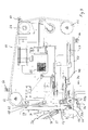
- the device shown in the figures is used in particular for laminating folded sheets for the purpose of producing a photobook block and is part of a system for producing such book blocks.
- a unwound from a roll material web is printed in a printing station, not shown in the figures; Alternatively or additionally, however, it is also conceivable that the material web delivered wound up on the roll has already been printed and / or coated and / or exposed. From the web are then separated by cross-cutting printed sheets. Alternatively you can also finished printed and / or coated and / or exposed sheets are provided for example by means of a sheet feeder. The sheets are folded or folded along a fold line, so that the fold line forms a folded or folded edge.
- the folded sheets which are also not shown in the figures, are transported by means of a transport station 2, which is part of the in Fig. 1 is shown arrangement.
- the transport station 2 has an endless conveyor belt 4, which is guided around a plurality of rollers 5 and 5a.
- the conveyor belt 4 is driven by a drive motor 6 whose output shaft is coupled in the illustrated embodiment via a drive belt 8 with the downstream roller 5a, around which also the conveyor belt 4 is deflected.
- several of these conveyor belts are provided as parallel spaced individual narrow conveyor belts.
- the conveyor belt 4 can also be designed as a suction conveyor belt.
- the transport station 2 is used in the illustrated arrangement to transport the sheet, not shown in the transport direction according to arrow A, which also indicates the process direction, in a downstream adhesive application station 10, at the same time an alignment of the sheet on the aforementioned side web and thus on the machine zero edge takes place.
- Fig. 2 can recognize the adhesive application station 10, a pair of feed rollers 12, a glue nozzle strip 14, a Glimdüsenance 14 connected to the Glue apparatus 16, a further transport roller 18 and a Glimauffangang20.
- the conveyor belt 4 of the transport station 2 is aligned with its upper run 4a so that it transports a sheet to the feed rollers 12, which feed the sheet into the adhesive application station 10 at the same speed.
- the feed rollers 12 are also driven by the drive motor 6 via the drive belt 8.
- the further transport roller 18 is arranged in the illustrated embodiment and lies below the Leimdüsenance 14.
- the glue nozzle strip 14 or the entire glue apparatus 16 with the glue nozzle strip 14 can be brought between a rest position and a working position and, for example, pivotably supported between an upper rest position and a lower working position.
- the glueing apparatus 16 is mounted in the illustrated embodiment on a frame 17 which is rotatably mounted about a pivot point 17a on a scaffold, not shown, and is offset by an eccentric 17b, which is offset by a drive, not shown in a corresponding rotational movement, against the tensile force of a Spring 17c is pivoted between the upper rest position and the lower working position.
- the Leimdüsenology 14 is divided for a format width change into segments, which is also not shown in the figures.
- the transport roller 18 may be pivotally mounted below the Leimdüsenology 14 between a working position in which it can be brought for the transport of a sheet in engagement with the underside, and a rest position, which is also not shown in the figures.
- a sensor also not shown in the figures, which detects the arrival and the presence of a sheet is arranged in the adhesive application station 10. Due to a corresponding signal from such a sensor, the sizing apparatus 16 is then controlled accordingly to apply glue from the glue jet bar 14 to the top of the sheet.
- the Glimdüsenance 14 and the transport roller 18 perform a movement to each other to the sheet with defined pressure against the Leimdüsenology 14 to press.
- the glue nozzle strip 14 and the transport roller 18 are mounted correspondingly movable, which is also not shown in the figures.
- the glue supply is switched on in Glimapparat 16 and applied the glue from the Glimdüsenance 14 on top of the sheet.
- the sheet driven by the feed rollers 12 and by the transport roller 18, is glued under the glue nozzle bar 14 on its upper side, recognizes the aforementioned, but not shown in the figures, the sensor sensor trailing edge and thus the end of the sheet and passes with a defined time delay, the interruption of the glue flow and thus switching off the glue device 14 a.
- the mentioned defined time delay is such that the top of the sheet is completely glued and the glue delivery from the Leimdüsenology 14 is switched off shortly after reaching the end of the arc.
- glue glue bar 14 and the transport roller 18 can each be spent in its rest position or pivoted and thereby moved apart.
- a Leimauffangor 20 is arranged, which extends as the Leimdüsenance 14 over the entire width of the transport path.
- the Leimauffangor 20 is disposed on the upper free end of a lever 22 which is pivotable about a hinge 24 between a rest position and a working position.
- the lever 22 is shown in its downwardly pivoted rest position with solid lines and in the upwardly pivoted working position with dashed lines.
- the glue tray 20 can be used during the gluing process to catch excess glue.
- an essential task of the glue tray 20 is related to see with the rinsing of Leimdüsenance 14. Because in a format change in width, the glue nozzle strip 14 and thus the nozzles located therein should be rinsed. Because the flushing causes a complete filling of Leimdüsenance 14, which then leads to a uniform glue application. The amount of glue that emerges during the rinsing process from the glue nozzle strip 14 can be collected with the glue collecting strip 20 and then removed from it.
- a transfer station 30 which forms an interface between the adhesive application station 10 and a stacking station 40, which will be explained in more detail later in the description.
- the transfer station 30 has an endlessly circulating suction belt 32, the upper run 32a of which forms a continuation of the transport path for the sheets out of the adhesive application station 10.
- the upper run 32a of the suction belt 32 has a downwardly curved course, from a substantially horizontal orientation in its upstream portion in the region of the adhesive application station 10 in an inclined by about 70 ° downward orientation at its downstream located adjacent to the stack forming station 40 at a location in Fig.
- suction belt 32 is denoted by the reference numeral "34" and on which the suction belt 32 is deflected.
- a plurality of such suction belts can be provided, which are arranged in parallel spaced from each other.
- the suction belt 32 should meet high temperature requirements at this point
- the suction belt 32 essentially runs around a suction box 36, in which a negative pressure is generated by a suction device, not shown in the figures.
- a suction box 36 In the top of the suction box 36, on which the upper run 32a of the suction belt 32 rests, suction holes are formed, which are not visible in the figures.
- the suction belt 32 is provided with holes, which are also not visible in the figures.
- the transfer station 30 ensures that the folded sheet is transported with its folded edge ahead in the vertical and thereby transferred to a strongly downwardly inclined orientation in the area indicated by the reference numeral "34", there is a risk that the now Essentially folded over folded sheet unintentionally unfolds.
- the unfolding of the sheet is favored in particular by the fact that the sheet adheres only to the underside of its lower layer on the suction belt 32, while the upper layer is not fixed in this respect and is even weighted with the glue, whereby an unintentional opening is even favored.
- spring plates are arranged on the inside of the side plates at a relatively short distance from the top of the upper run 32a of the suction belt 32, which serve as a plant or attacks and their schematic Presentation in Fig. 2 designated by the reference numeral "38".
- the stack is formed on the surface 42a of the abutment plate 42 in the horizontal direction and therefore is not horizontal, but stands upright or edgewise.
- FIG. Fig. 3 is marked by a dashed circle, which is designated by the reference numeral "44".
- These include a horizontally arranged, plate-shaped bottom slide 46 whose surface 46a (FIG. Fig. 4 ) forms a horizontal plane in the illustrated embodiment.
- the bottom slide 46 is displaceably mounted by means of an adjusting device 47 between a rest position and a working position. In the rest position, the bottom slide 46, which like the adjusting device 47 belongs to the stack forming station 40, is fully retracted into the stack forming station 40; in the Figures 3 and 4 the bottom slide 46 is shown in its working position.
- a plurality of clamping fingers 50 are arranged, which in the illustrated embodiment between a rest position and a working position can be pivoted by 90 °.
- the pivot fingers are aligned in the horizontal direction parallel to the top 46 a and the edge 46 b of the bottom slide 46.
- the clamping fingers 50 are pivoted by 90 ° upwards so that they now protrude above the top 46a of the bottom slide 46 also upwards, which is not shown in the figures.
- the alignment region 44 also includes a pressure plate 52, which is arranged adjacent below the point indicated by the reference numeral "34" and thus the downstream end of the transfer station 30.
- the pressure plate 52 can be moved between an open position and a closed position, preferably pivotably mounted. In the FIGS. 1 to 3 the pressure plate 52 is shown in its closed position. In the open position, the distance of the pressure plate 52 to the contact plate 42 is greater, so that the pressure plate 52 in the representation of FIGS. 1 to 3 to move to the left is to spend it in the open position.
- the pressure plate 52 has the function to spend the sheet in the direction of the surface 42 a of the abutment plate 42 and thus to lead to the stacking station 40.
- the pressure plate 52 is initially in its open position.
- the pressure plate 52 is moved to its closed position and brought into abutment against the lower edge portion of the sheet adjacent to its folded edge.
- the sheet reaches its folded edge in support on the top 46a of the already extended in its working position bottom slide 46, while the clamping fingers 50 are still in their rest position.
- the pressure plate 52 the sheet is then pressed in the direction of the contact plate 42 and thereby against the stack already formed there.
- the clamping fingers 50 are pivoted into their upright working position to grip the sheet and fix it on the bottom slide 46.
- Fig. 4 can also be seen, along the two vertical sides of the surface 42a of the abutment plate 42 inwardly bent spring plates 54 are arranged, which serve to fix the already formed on the support plate 42 stack.
- the surface 42a of the abutment plate 42 is provided with a plurality of holes, which are suction ports, which are connected via not shown hoses and / or pipes to a suction device, also not shown. From these intake ports, for example, a few suction in Fig. 4 marked with the reference numeral "56".
- the abutment plate 42 acts as a suction plate.
- the abutment plate 42 is provided with a first recess 42b, in which a first retaining finger 58 is seated, which is movably supported by an adjusting device, not shown, between a retracted rest position and an extended working position in the stack forming station 40.
- the abutment plate 42 is provided with a further recess 42c which extends almost over the entire width of the abutment plate 42 and receives a second retaining finger 59 which not only by means of an adjustment, not shown between a retracted into the stack forming station 40 and rest position one out of this extended working position, but also over the entire length of the recess 42c is adjustable.
- These retention fingers 58, 59 are used as an alternative to the bent spring plates 54 in narrower formats to stabilize the stack abutting the surface 42a of the abutment plate 42.
- the newly supplied Sheet to press all over against the already formed stack. This is done in the illustrated embodiment by means of a laminating or pressure roller 60, which moves through the stack forming area 48 from bottom to top and like a dough roller the new sheet rubs against the stack.
- a plurality of pressure rollers 60 are movably mounted along a closed guide track extending through the stack formation area 48, which is not shown in the figures, and in this case are arranged substantially equidistant from one another.
- two spaced-apart conveyor chains are provided in the illustrated embodiment, of which a conveyor chain is arranged on one side of the stack forming station 40 and the other conveyor chain on the opposite other side of the stack forming station 40 and guided over deflection rollers.
- Fig. 3 is the viewer facing conveyor chain 62 recognizable, which is guided by gears 64 and deflected to this, which are rotatably mounted in the stacking station 40.
- the arrangement and the course of the two conveyor chains 62 are identical. Between the two conveyor chains 62, the pressure rollers 60 are arranged horizontally, by a pin 60a at its respective end ( Fig. 4 ) are mounted in a bearing element, not shown, which is attached to the associated conveyor chain 62.
- At least one of the rollers 64 is set in rotation by an unspecified drive unit.
- the circulation operation takes place in the clockwise direction.
- a pressure roller 60 is provided for each newly delivered sheet.
- the distance between two adjacent pressure rollers and the working stroke of the system are to be dimensioned or adjusted in dependence on each other such that a new pressure roller 60 is provided for each newly delivered sheet.
- the same procedure described above applies to each additional glued sheet delivered.
- the clamping fingers 50 ( Fig. 4 ) hold the already formed and laminated stack back and ensure a precise hiring of the newly delivered and to be laminated bow.
- one of the pressure rollers 60 moves up through the stack formation area 48 and rubs the new sheet against the stack on the support plate 42.
- the stacking station 40 which can alternatively also be referred to as a laminating station, has an adjusting device 66 in order to adjust the abutment plate 42 in the horizontal direction and thus perpendicularly to its vertical surface 42a.
- the abutment plate 42 is cyclically retracted during the stack formation by the adjusting device 66 such that the upper side of the stack remains substantially stationary. Accordingly, the abutment plate 42 is continuously displaced to the stacking station 40 by the adjustment device 66, depending on the thickness of the stack and in dependence on the increasing height or thickness of the growing stack, and thus, according to the illustration of the figures, to the right.
- the distance of the pressure rollers 60 guided through the stack forming area 48 does not need to be readjusted individually depending on the instantaneous height or thickness of the stack formed up to that point, but a constant guidance is sufficient for all the pressure rollers 60 through the stack formation area 48. which is constructively advantageous.
- the bottom slide 46 After completion of the stack with the respective predetermined number of sheets and completion of the previously described laminating the bottom slide 46 is moved by the adjusting device 47 of his in the Figures 3 and 4 shown working position in the representation according to the Figures 3 and 4 pulled back to the right to the rest position.
- the bottom stop of the stack formation area 48 disappears or the bottom opens, and the stack falls vertically downwards in the direction of its longitudinal extent.
- the stack is caught by an underlying pliers 70, which in the Figures 3 and 4 is shown recognizable.
- the forceps 70 has two to each other movable jaws 72a, 72b for opening and closing the pliers 70 and a stop 74 on.
- the pliers 70 is movably arranged on a holder, not shown, and is actuated by a drive, also not shown, which preferably operates electropneumatically or electromechanically and may preferably be designed as a linear drive.
Applications Claiming Priority (1)
| Application Number | Priority Date | Filing Date | Title |
|---|---|---|---|
| DE102011006896A DE102011006896A1 (de) | 2011-04-06 | 2011-04-06 | Vorrichtung zur Herstellung eines Buchblockes |
Publications (1)
| Publication Number | Publication Date |
|---|---|
| EP2508351A2 true EP2508351A2 (fr) | 2012-10-10 |
Family
ID=45992074
Family Applications (1)
| Application Number | Title | Priority Date | Filing Date |
|---|---|---|---|
| EP12162044A Withdrawn EP2508351A2 (fr) | 2011-04-06 | 2012-03-29 | Dispositif destiné à la fabrication d'un bloc de livre |
Country Status (6)
| Country | Link |
|---|---|
| US (1) | US20120257947A1 (fr) |
| EP (1) | EP2508351A2 (fr) |
| JP (1) | JP2012218444A (fr) |
| CN (1) | CN102815108A (fr) |
| BR (1) | BR102012008186A2 (fr) |
| DE (1) | DE102011006896A1 (fr) |
Families Citing this family (1)
| Publication number | Priority date | Publication date | Assignee | Title |
|---|---|---|---|---|
| ITMI20111016A1 (it) * | 2011-06-06 | 2012-12-07 | Sitma Machinery S P A | Gruppo e metodo per la realizzazione in continuo di sovracopertine di varie dimensioni a partire da una pellicola avvolta in bobina |
Citations (2)
| Publication number | Priority date | Publication date | Assignee | Title |
|---|---|---|---|---|
| DE4141767A1 (de) | 1991-12-18 | 1993-06-24 | Will E C H Gmbh & Co | Verfahren und anordnung zum herstellen von buechern und broschueren |
| EP0791478A1 (fr) | 1996-02-23 | 1997-08-27 | Kabushiki Kaisha Kanpuri | Dispositif et méthode pour relier |
Family Cites Families (6)
| Publication number | Priority date | Publication date | Assignee | Title |
|---|---|---|---|---|
| US6616135B1 (en) * | 1999-11-08 | 2003-09-09 | Konica Corporation | Bookbinding apparatus using pasting process |
| EP1116600A3 (fr) * | 2000-01-11 | 2002-03-06 | Hewlett-Packard Company, A Delaware Corporation | Dispositif et méthode pour relier des feuilles |
| AUPR157500A0 (en) * | 2000-11-20 | 2000-12-14 | Silverbrook Research Pty. Ltd. | An apparatus and method (bin02) |
| US6799759B1 (en) * | 2003-03-27 | 2004-10-05 | Xerox Corporation | Booklet maker with contact member |
| JP4541906B2 (ja) * | 2004-01-27 | 2010-09-08 | キヤノン株式会社 | シート束背面折り部平坦処理装置、シート処理装置、及び画像形成装置 |
| JP4857064B2 (ja) * | 2006-09-29 | 2012-01-18 | キヤノン株式会社 | 製本装置 |
-
2011
- 2011-04-06 DE DE102011006896A patent/DE102011006896A1/de not_active Ceased
-
2012
- 2012-03-29 EP EP12162044A patent/EP2508351A2/fr not_active Withdrawn
- 2012-04-05 JP JP2012086814A patent/JP2012218444A/ja active Pending
- 2012-04-05 US US13/440,161 patent/US20120257947A1/en not_active Abandoned
- 2012-04-06 CN CN201210288485.XA patent/CN102815108A/zh active Pending
- 2012-04-09 BR BR102012008186-5A patent/BR102012008186A2/pt not_active IP Right Cessation
Patent Citations (2)
| Publication number | Priority date | Publication date | Assignee | Title |
|---|---|---|---|---|
| DE4141767A1 (de) | 1991-12-18 | 1993-06-24 | Will E C H Gmbh & Co | Verfahren und anordnung zum herstellen von buechern und broschueren |
| EP0791478A1 (fr) | 1996-02-23 | 1997-08-27 | Kabushiki Kaisha Kanpuri | Dispositif et méthode pour relier |
Also Published As
| Publication number | Publication date |
|---|---|
| BR102012008186A2 (pt) | 2014-02-11 |
| CN102815108A (zh) | 2012-12-12 |
| DE102011006896A1 (de) | 2012-10-11 |
| US20120257947A1 (en) | 2012-10-11 |
| JP2012218444A (ja) | 2012-11-12 |
Similar Documents
| Publication | Publication Date | Title |
|---|---|---|
| EP2457738B1 (fr) | Procédé de reliure par collage d'un bloc de livre avec feuille de garde | |
| EP1764232B1 (fr) | Méthode et dispositif pour la fabrication des journaux imprimés de façon numérique | |
| EP2727869B1 (fr) | Dispositif et procédé destinés à plier des feuilles imprimées | |
| EP2508353A2 (fr) | Machine destinée à la fabrication de livres, notamment livres photo et/ou livres illustrés | |
| EP3085502B1 (fr) | Procede de decoupage des rebords d'un produit imprime | |
| EP1344655A2 (fr) | Dispositif pour la production des blocs de livres et des brochures reliés par colle, particulièrement pour petits lots | |
| EP2508352A2 (fr) | Dispositif d'assemblage de blocs de livres et de couvertures de livres | |
| EP2517892B1 (fr) | Dispositif et procédé de fabrication d'un bloc de livre relié présentant une bande à onglets ou une couverture | |
| EP1914165A1 (fr) | Procédé et dispositif destinés à former une rangée d'objets plats | |
| EP2397339A2 (fr) | Procédé et dispositif destinés à la fabrication de couvertures de livre | |
| EP1939008A2 (fr) | Assembleuse et brocheuse dotée d'une chaîne variable | |
| EP1528023B1 (fr) | Méthode et dispositif pour changer un flux d'articles plats | |
| EP3482892A2 (fr) | Dispositif pour l'exécution d'opérations de coupe de bords de format ouverts d'un produit imprimé | |
| EP0169489B1 (fr) | Dispositif pour plier et transformer des imprimés | |
| EP1834804B1 (fr) | Procédé et dispositif destinés à l'installation d'une enveloppe | |
| DE2741332A1 (de) | Verfahren zur herstellung eines buchblocks sowie vorrichtung zur durchfuehrung des verfahrens | |
| EP2508351A2 (fr) | Dispositif destiné à la fabrication d'un bloc de livre | |
| EP3059092B1 (fr) | Dispositif de fabrication de produits imprimes relies par encollage | |
| EP2165847A1 (fr) | Procédé et dispositif de fabrication de produits d'impression | |
| DE102010022618A1 (de) | Klebebinder insbesondere für hochqualitative Kleinauflagen | |
| DE3444576A1 (de) | Verfahren und vorrichtung zur herstellung von buechern, insbesondere taschenbuechern, broschueren und zeitschriften | |
| DE19602610B4 (de) | Verfahren und Vorrichtung zur Bearbeitung von Bogenstapeln | |
| DE3419610A1 (de) | Verfahren und vorrichtung zum anbringen von deckblaettern an bloecken | |
| EP3210918B1 (fr) | Amenée de produits imprimés de différentes épaisseurs | |
| EP2275278B1 (fr) | Dispositif transversale et procédé pour adhérer le papier garniture |
Legal Events
| Date | Code | Title | Description |
|---|---|---|---|
| PUAI | Public reference made under article 153(3) epc to a published international application that has entered the european phase |
Free format text: ORIGINAL CODE: 0009012 |
|
| AK | Designated contracting states |
Kind code of ref document: A2 Designated state(s): AL AT BE BG CH CY CZ DE DK EE ES FI FR GB GR HR HU IE IS IT LI LT LU LV MC MK MT NL NO PL PT RO RS SE SI SK SM TR |
|
| AX | Request for extension of the european patent |
Extension state: BA ME |
|
| STAA | Information on the status of an ep patent application or granted ep patent |
Free format text: STATUS: THE APPLICATION IS DEEMED TO BE WITHDRAWN |
|
| 18D | Application deemed to be withdrawn |
Effective date: 20151001 |