EP3085485B1 - Resistance spot welding method - Google Patents
Resistance spot welding method Download PDFInfo
- Publication number
- EP3085485B1 EP3085485B1 EP14870854.8A EP14870854A EP3085485B1 EP 3085485 B1 EP3085485 B1 EP 3085485B1 EP 14870854 A EP14870854 A EP 14870854A EP 3085485 B1 EP3085485 B1 EP 3085485B1
- Authority
- EP
- European Patent Office
- Prior art keywords
- current
- conduction
- pulsation
- spatter
- spot welding
- Prior art date
- Legal status (The legal status is an assumption and is not a legal conclusion. Google has not performed a legal analysis and makes no representation as to the accuracy of the status listed.)
- Not-in-force
Links
- 238000003466 welding Methods 0.000 title claims description 115
- 238000000034 method Methods 0.000 title claims description 53
- 230000010349 pulsation Effects 0.000 claims description 140
- 229910000831 Steel Inorganic materials 0.000 claims description 131
- 239000010959 steel Substances 0.000 claims description 131
- 229910052782 aluminium Inorganic materials 0.000 claims description 12
- XAGFODPZIPBFFR-UHFFFAOYSA-N aluminium Chemical compound [Al] XAGFODPZIPBFFR-UHFFFAOYSA-N 0.000 claims description 12
- 239000011701 zinc Substances 0.000 claims description 9
- 229910052725 zinc Inorganic materials 0.000 claims description 8
- HCHKCACWOHOZIP-UHFFFAOYSA-N Zinc Chemical compound [Zn] HCHKCACWOHOZIP-UHFFFAOYSA-N 0.000 claims description 7
- 239000011248 coating agent Substances 0.000 claims description 3
- 238000000576 coating method Methods 0.000 claims description 3
- XLOMVQKBTHCTTD-UHFFFAOYSA-N Zinc monoxide Chemical compound [Zn]=O XLOMVQKBTHCTTD-UHFFFAOYSA-N 0.000 description 18
- 230000000694 effects Effects 0.000 description 15
- 238000007747 plating Methods 0.000 description 14
- 238000003825 pressing Methods 0.000 description 13
- 239000000463 material Substances 0.000 description 12
- 230000020169 heat generation Effects 0.000 description 11
- XEEYBQQBJWHFJM-UHFFFAOYSA-N Iron Chemical compound [Fe] XEEYBQQBJWHFJM-UHFFFAOYSA-N 0.000 description 10
- 238000001816 cooling Methods 0.000 description 10
- 238000010438 heat treatment Methods 0.000 description 9
- 239000011787 zinc oxide Substances 0.000 description 9
- RYGMFSIKBFXOCR-UHFFFAOYSA-N Copper Chemical compound [Cu] RYGMFSIKBFXOCR-UHFFFAOYSA-N 0.000 description 7
- 229910052802 copper Inorganic materials 0.000 description 7
- 239000010949 copper Substances 0.000 description 7
- 229910052751 metal Inorganic materials 0.000 description 7
- 239000002184 metal Substances 0.000 description 7
- 230000000052 comparative effect Effects 0.000 description 6
- 229910052742 iron Inorganic materials 0.000 description 5
- 238000002844 melting Methods 0.000 description 5
- 230000008018 melting Effects 0.000 description 5
- 230000015572 biosynthetic process Effects 0.000 description 4
- 238000004519 manufacturing process Methods 0.000 description 4
- 230000008602 contraction Effects 0.000 description 3
- 230000008021 deposition Effects 0.000 description 3
- 239000007787 solid Substances 0.000 description 3
- 239000000243 solution Substances 0.000 description 3
- VYZAMTAEIAYCRO-UHFFFAOYSA-N Chromium Chemical compound [Cr] VYZAMTAEIAYCRO-UHFFFAOYSA-N 0.000 description 2
- 238000005275 alloying Methods 0.000 description 2
- 239000010960 cold rolled steel Substances 0.000 description 2
- 229910000765 intermetallic Inorganic materials 0.000 description 2
- 238000012886 linear function Methods 0.000 description 2
- 238000012887 quadratic function Methods 0.000 description 2
- 230000000630 rising effect Effects 0.000 description 2
- 238000007711 solidification Methods 0.000 description 2
- 230000008023 solidification Effects 0.000 description 2
- XLYOFNOQVPJJNP-UHFFFAOYSA-N water Substances O XLYOFNOQVPJJNP-UHFFFAOYSA-N 0.000 description 2
- 229910018125 Al-Si Inorganic materials 0.000 description 1
- 229910018520 Al—Si Inorganic materials 0.000 description 1
- 229910003023 Mg-Al Inorganic materials 0.000 description 1
- OAICVXFJPJFONN-UHFFFAOYSA-N Phosphorus Chemical compound [P] OAICVXFJPJFONN-UHFFFAOYSA-N 0.000 description 1
- 229910000797 Ultra-high-strength steel Inorganic materials 0.000 description 1
- 229910009369 Zn Mg Inorganic materials 0.000 description 1
- 229910007570 Zn-Al Inorganic materials 0.000 description 1
- 229910007573 Zn-Mg Inorganic materials 0.000 description 1
- 229910007567 Zn-Ni Inorganic materials 0.000 description 1
- 229910007614 Zn—Ni Inorganic materials 0.000 description 1
- 229910045601 alloy Inorganic materials 0.000 description 1
- 239000000956 alloy Substances 0.000 description 1
- 238000000137 annealing Methods 0.000 description 1
- 239000011230 binding agent Substances 0.000 description 1
- 239000006229 carbon black Substances 0.000 description 1
- 238000006243 chemical reaction Methods 0.000 description 1
- 238000004040 coloring Methods 0.000 description 1
- 230000007797 corrosion Effects 0.000 description 1
- 238000005260 corrosion Methods 0.000 description 1
- 238000005336 cracking Methods 0.000 description 1
- 230000001419 dependent effect Effects 0.000 description 1
- 239000007772 electrode material Substances 0.000 description 1
- 238000011156 evaluation Methods 0.000 description 1
- 238000000227 grinding Methods 0.000 description 1
- 235000019589 hardness Nutrition 0.000 description 1
- 238000005304 joining Methods 0.000 description 1
- 229910000734 martensite Inorganic materials 0.000 description 1
- 229910052698 phosphorus Inorganic materials 0.000 description 1
- 239000011574 phosphorus Substances 0.000 description 1
- 238000001556 precipitation Methods 0.000 description 1
- 230000002265 prevention Effects 0.000 description 1
- 229920006395 saturated elastomer Polymers 0.000 description 1
- 238000005204 segregation Methods 0.000 description 1
- 238000004904 shortening Methods 0.000 description 1
- 239000002002 slurry Substances 0.000 description 1
- 239000006104 solid solution Substances 0.000 description 1
- 230000001629 suppression Effects 0.000 description 1
- 230000003746 surface roughness Effects 0.000 description 1
- 229920002803 thermoplastic polyurethane Polymers 0.000 description 1
Images


Classifications
-
- B—PERFORMING OPERATIONS; TRANSPORTING
- B23—MACHINE TOOLS; METAL-WORKING NOT OTHERWISE PROVIDED FOR
- B23K—SOLDERING OR UNSOLDERING; WELDING; CLADDING OR PLATING BY SOLDERING OR WELDING; CUTTING BY APPLYING HEAT LOCALLY, e.g. FLAME CUTTING; WORKING BY LASER BEAM
- B23K11/00—Resistance welding; Severing by resistance heating
- B23K11/24—Electric supply or control circuits therefor
-
- B—PERFORMING OPERATIONS; TRANSPORTING
- B23—MACHINE TOOLS; METAL-WORKING NOT OTHERWISE PROVIDED FOR
- B23K—SOLDERING OR UNSOLDERING; WELDING; CLADDING OR PLATING BY SOLDERING OR WELDING; CUTTING BY APPLYING HEAT LOCALLY, e.g. FLAME CUTTING; WORKING BY LASER BEAM
- B23K11/00—Resistance welding; Severing by resistance heating
- B23K11/10—Spot welding; Stitch welding
- B23K11/11—Spot welding
- B23K11/115—Spot welding by means of two electrodes placed opposite one another on both sides of the welded parts
-
- B—PERFORMING OPERATIONS; TRANSPORTING
- B23—MACHINE TOOLS; METAL-WORKING NOT OTHERWISE PROVIDED FOR
- B23K—SOLDERING OR UNSOLDERING; WELDING; CLADDING OR PLATING BY SOLDERING OR WELDING; CUTTING BY APPLYING HEAT LOCALLY, e.g. FLAME CUTTING; WORKING BY LASER BEAM
- B23K11/00—Resistance welding; Severing by resistance heating
- B23K11/16—Resistance welding; Severing by resistance heating taking account of the properties of the material to be welded
- B23K11/163—Welding of coated materials
-
- B—PERFORMING OPERATIONS; TRANSPORTING
- B23—MACHINE TOOLS; METAL-WORKING NOT OTHERWISE PROVIDED FOR
- B23K—SOLDERING OR UNSOLDERING; WELDING; CLADDING OR PLATING BY SOLDERING OR WELDING; CUTTING BY APPLYING HEAT LOCALLY, e.g. FLAME CUTTING; WORKING BY LASER BEAM
- B23K11/00—Resistance welding; Severing by resistance heating
- B23K11/24—Electric supply or control circuits therefor
- B23K11/241—Electric supplies
Definitions
- the present invention relates to a resistance spot welding method for welding a plurality of steel sheets according to the preamble of claim 1 (see, for example, US 2013/087533 A1 ), more particularly relates to a resistance spot welding method using an inverter DC power supply.
- Car bodies are mainly assembled by joining press-formed steel sheets by resistance spot welding.
- resistance spot welding used in the assembly of car bodies, both securing a nugget size corresponding to the sheet thickness and suppressing the occurrence of spatter are sought.
- a range defined by a current value giving a 4 ⁇ t ("t" shows the sheet thickness (mm)) or other reference nugget size as a lower limit (below, referred to as the “lower limit current” or “4 ⁇ t current”) and a current value where spatter occurs as an upper limit (below, referred to as “upper limit current” or “spatter current”) (below, referred to as a "suitable current range”) is considered an important indicator relating to spot welding of steel sheets.
- the lower limit current and the upper limit current are measured in the ideal state at the test piece.
- Spatter includes inner spatter (the phenomenon of metal of the base material melted by the welding scattering from the superposed surfaces of the steel sheets) and outer spatter (the phenomenon of the base material metal melted by the welding scattering from the contact surfaces of the steel sheets and electrodes).
- inner spatter the phenomenon of metal of the base material melted by the welding scattering from the superposed surfaces of the steel sheets
- outer spatter the phenomenon of the base material metal melted by the welding scattering from the contact surfaces of the steel sheets and electrodes.
- the surface quality is lowered by scattering and sticking to the car body. Further, sticking to the moving parts of a welding robot causes poor operation of the equipment.
- the outer spatter remaining in needle shapes on the surface of a spot welded part becomes a cause of damage to the wire harnesses of automobiles etc., so a grinder has to be used for grinding away the spatter. For this reason, it is required that in resistance spot welding, inner spatter and outer spatter be avoided and a predetermined nugget size be secured
- the lower limit current is evaluated in the ideal state at the test piece level.
- a current value of 1.0 kA or more, preferably 1.5 kA or more, higher than the current giving 4 ⁇ t at the test piece level as a realistic lower limit current value.
- the suitable current range in evaluation at the test piece level is required to be 1.0 kA or more, preferably 1.5 kA or more. This is because if a predetermined suitable current range cannot be secured at the test piece level, it is necessary to set the current value at a current where spatter occurs to stably secure a 4 ⁇ t nugget size in spot welding at the actual worksite where there are many outside disturbances.
- inverter DC type instead of the single-phase AC type have increasingly been used.
- the inverter DC type enables the transformer to be made smaller, so there is the merit of enabling a robot with a small carrying load to carry it, so this is particularly often used on automated lines.
- the inverter DC type does not turn the current on and off like the conventionally used single-phase AC system but continuously applies current, so the heat generation efficiency is good. For this reason, it is reported that even in the case of a zinc-plated material of thin sheet soft steel where formation of a nugget is difficult, a nugget is formed from a low current and the suitable current range is broader than the single-phase AC system.
- JP 2010-188408 A discloses a method employing a two-stage conduction system using preliminary conduction to improve the fit between contact surfaces of the steel sheets, then perform the main conduction so as to suppress the occurrence of spatter in resistance spot welding of high tensile steel sheets.
- JP 2003-236674 A discloses a method employing a conduction system using preliminary conduction to improve the fit between contact surfaces of the steel sheets, then stopping the current, then using main conduction so as to suppress the occurrence of spatter in resistance spot welding of high tensile steel sheets.
- JP 2010-207909 A has a three-stage conduction process. That is, it is comprised of a first step of forming a nugget as a preliminary conduction step, a second step of making the current fall after the preliminary conduction and increasing a corona bond area around the nugget, and a third step of running a current larger than the preliminary conduction current after the second step and enlarging the nugget size as a main conduction step.
- JP 2010-207909 A discloses making the third step a pulsation conduction system to thereby make the effect of expansion of the conduction diameter greater and suppress the occurrence of spatter compared with the continuous conduction system.
- JP 2006-181621 A discloses a method of using resistance spot welding repeating an up-down change of current while raising the current value to suppress the occurrence of spatter in resistance spot welding of high tensile steel sheets.
- the surface of a steel sheet used for hot stamping is sometimes nonplated and sometimes zinc-based plated, aluminum-based plated, or otherwise surface-treated to prevent formation of iron scale when heated to a high temperature.
- a hot stamped steel sheet is in many cases not a flat sheet but a shape.
- high tensile steel sheet which is hot stamped will be referred to as "hot stamped steel sheet” including the case of shapes.
- zinc-based plated steel sheet, aluminum-based plated steel sheet, or such steel sheet further coated on the surface which is hot stamped will be referred to as "surface-treated hot stamped steel sheet".
- surface-treated hot stamped steel sheet becomes more susceptible to inner spatter along with outer spatter and remarkably narrower in suitable current range with an inverter DC power supply. For this reason, the nugget size obtained without the occurrence of spatter also becomes smaller.
- inner spatter may occur as follows: At the spot welded part, there is a press bonded part (corona bond part) pressed by the electrodes around the melted and solidified nugget in which the molten metal is sealed. If the inside pressure of the molten metal exceeds the outside pressure acting on the corona bond part, it no longer becomes possible to seal in the molten metal and inner spatter will occur. In general, if the press bonded part becomes narrower, the internal pressure will no longer be able to be withstood and spatter will easily occur. For this reason, to suppress the occurrence of spatter, it is necessary to improve the fit between one steel sheet and the other steel sheet and widen the press bonded part and to avoid sudden heat generation so that the nugget gradually grows.
- the surface-treated hot stamped steel sheet has an oxide film mainly comprised of metal derived from the plating at the steel sheet surface (for example, if zinc-based plating, zinc, while if aluminum-based plating, aluminum) or an oxide film derived from the surface coating. For this reason, compared with bare steel sheet, the position where current flows at the steel sheet surface becomes local and increased current density is apt to cause rapid generation of heat. On the other hand, in the hot stamping process, alloying of the plating and steel proceeds and the melting point of the alloy formed at the steel sheet surface also becomes a high temperature close to iron. For this reason, compared with steel sheet provided with a plating film before heating, the contact parts of the steel sheets soften, so expansion of the conduction path is suppressed.
- the inverter DC system is higher in heat generation efficiency compared with the single-phase AC system due to the continuous input of current, so the formation of the nugget at the initial stage of conduction is extremely fast. For this reason, it is believed the growth of the press bonded part around the nugget cannot be kept up with and the molten metal can no longer be sealed in, so inner spatter occurs.
- the cause of occurrence of outer spatter is similar. Due to the effect of the oxide film etc., the resistance becomes higher at the contact parts of the steel and electrodes and the amount of heat generation becomes larger.
- the inverter DC system is a continuous conduction system. There is no current idle time such as with the single-phase AC system, so the cooling efficiency by the copper electrode becomes hard to obtain. For this reason, it is believed that the nugget easily grows in the sheet thickness direction, the melted part reaches up to right below the outermost layer of the steel sheet, and outer spatter occurs.
- JP 2010-188408 A is a resistance spot welding method of high tensile steel sheet.
- the current value able to be given without causing spatter in the initial first conduction is low, but the effect of suppression of spatter by widening the conduction path and lowering the current density is not sufficient. For this reason, if raising the current in the second half of conduction, cases are recognized where inner spatter and and outer spatter occur. This is insufficient for securing a suitable current range.
- JP2003-236674 A in the same way as in JP 2010-188408 A , is lower in current value able to be given in the initial first conduction without causing spatter in surface-treated hot stamped steel sheet.
- the upper limit current rises, but if raising the current in the second stage, cases of occurrence of inner spatter are observed. This method was still insufficient for securing a suitable current range.
- JP 2010-207909 A only shows examples of single-phase AC spot welding machines.
- the case of inverter DC spot welding machines is not confirmed.
- the case of 980 MPa high tensile steel is explained, but the case of surface-treated hot stamped material susceptible to spatter is not explained.
- the inventors used an inverter DC spot welding machine to investigate the effect of the art of JP 2010-207909 A in surface-treated hot stamped steel sheet.
- the effect was still insufficient. This could not be directly applied to resistance welding of surface-treated hot stamped steel sheet susceptible to surface spatter.
- this is even truer in resistance welding using an inverter DC power supply when the current density becomes higher compared with a single-phase AC power supply system.
- JP 2006-181621 A has the effect of broadening the suitable current range up to steel materials with a tensile strength of the 980 MPa class, but in higher strength surface-treated hot stamped steel sheet, inner spatter and outer spatter easily occur at the time of the second or third upward change in current.
- This conduction pattern is not suitable for welding hot stamped materials.
- US 2013/087533 A1 discloses methods and systems for resistance spot welding using direct current micro pulses, in which the methods comprise forming a weld joint by applying a plurality of direct current micro pulses to at least two pieces of materials through a first electrode and a second electrode.
- US 2013/088037 A1 discloses a lightweight steel door for vehicle and method for manufacturing the same.
- GB 1 023 305 A discloses an apparatus for welding employing controllable power pulses, the apparatus including control means for controlling the conduction of the controllable solid state switching device so as to produce the discrete welding current pulses with a duration and frequency independently variable in order to regulate precisely the power supplied to the welding electrodes.
- the present invention has as its object to apply an inverter DC power supply to lap resistance spot welding of surface-treated hot stamped steel sheets and hot stamped steel sheets. That is, it has as its object to provide an inverter DC power supply system resistance spot welding method which can suppress the occurrence of outer spatter and inner spatter and can secure a broad suitable current range.
- the inventors used an inverter DC type spot welding power supply, engaged in studies using 1500 MPa class surface-treated hot stamped steel sheets, and thereby obtained the following discoveries.
- the present invention in resistance spot welding of high tensile steel sheets superposed, even if using an inverter DC power supply, it is possible to suppress the occurrence of outer spatter and inner spatter while enlarging the nugget size in resistance spot welding. Therefore, if using the resistance spot welding method according to the present invention, even with steel sheets extremely susceptible to spatter such as surface-treated hot stamped steel sheets, efficient, stable resistance spot welding becomes possible.
- the combination of sheets covered by the present invention is comprised of two or more steel sheets, at least one of which is a 590 MPa class or more high tensile steel sheet, superposed. In normal assembly of car bodies, two or three steel sheets superposed are welded by resistance spot welding.
- the type of the high tensile steel sheet is not particularly limited.
- the invention can be applied to precipitation strengthened steel sheet, DP steel sheet, TRIP (work induced transformed) steel sheet, hot stamped steel sheet, or other tensile strength 590 MPa or more high tensile steel sheet.
- the resistance spot welding method according to the present invention exhibits its effect by being performed on combinations of sheets including tensile strength 980 MPa or more high tensile steel sheet.
- the method is preferably applied to a combination of sheets including a high tensile steel sheet with a tensile strength of 1200 MPa or more, more preferably is applied to a combination of sheets including a high tensile steel sheet with a tensile strength of 1500 MPa or more.
- the high tensile steel sheet may be cold rolled steel sheet or may be hot rolled steel sheet. Furthermore, the presence or absence of plating is not an issue. Plated steel sheet is acceptable while nonplated steel sheet is also possible. Further, in the case of plated steel sheet, the type of plating is also not particularly limited.
- the present invention is effective for various high tensile steel sheets, but the effect of the present invention is particularly exhibited in surface-treated hot stamped steel sheet with a narrow suitable current range.
- the surface-treated hot stamped steel sheet is formed on its surface with a solid solution of intermetallic compounds and iron by an alloying reaction between a zinc-based (pure Zn, Zn-Fe, Zn-Ni, Zn-Al, Zn-Mg, Zn-Mg-Al, etc.) or aluminum-based (Al-Si etc.) plating film and the steel of the base material. Furthermore, these surfaces are formed with an oxide layer mainly comprised of zinc or aluminum.
- the surface of the film mainly comprised of intermetallic compounds of iron and aluminum is formed with a film mainly comprised of zinc oxide for improving the corrosion resistance.
- the surface-treated hot stamped steel sheet includes such oxides at its surface, so it is believed that inner spatter and outer spatter easily occur.
- the suitable current range is often less than 1 kA.
- the thickness of the high tensile steel sheet is not particularly limited. In general, the thickness of the steel sheet used in auto parts or car bodies is 0.6 to 3.2 mm. The resistance spot welding according to the present invention has sufficient effect in this range.
- the welding machine used in the present invention is an inverter DC system resistance spot welding machine.
- Resistance spot welding machines include the single-phase AC system and inverter DC system.
- On the other hand, with the inverter DC system while a high heat generation efficiency is exhibited, inner spatter and outer spatter occur more easily with a low current value. For this reason, the inverter DC system is narrower in suitable current range.
- the resistance spot welding method according to the present invention is predicated on solution of the problem of inverter DC type spot welding.
- the pressing mechanism in the resistance spot welding may be pressing by a servo motor or pressing by air. Further, for the shape of the gun, a stationary type, C-type, or X-type may be used.
- the pressing force at the time of welding is not particularly limited. During the resistance spot welding, the pressing force may be constant or the pressing force may be changed at the different steps.
- the pressing force is preferably 200 to 600 kgf.
- the electrodes in the resistance spot welding are also not particularly limited. DR type electrodes with tip diameters of 6 to 8 mm may be mentioned. As the most representative example, there are DR type electrodes with tip diameters of 6 mm and tip R40 mm.
- the electrode material either chrome copper or aluminum dispersed copper electrodes may be used, but from the viewpoint of prevention of fusing and outer spatter, aluminum dispersed copper is preferable.
- the pulsation conduction system is employed.
- Pulsation conduction means application of a pulse-like constant current while pressing one location in resistance spot welding and is comprised of one or more current pulses.
- an inverter DC power supply is used, so the current pulse (below, also simply referred to as a "pulse") becomes a rectangular or trapezoidal pulse waveform.
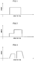
- FIG. 8A shows a typical pulse waveform of a rectangular pulse waveform.
- the abscissa shows the time, while the ordinate shows the weld current applied.
- Ia corresponding to the height of the rectangle is the applied weld current.
- the ta corresponding to the width of the rectangle is the conduction time of the pulse, while the interval ti with the adjoining pulse is the conduction idle time of pulses, the so-called interval.
- the conduction time, conduction idle time, and weld current can be variably controlled for each pulse. By controlling these, it is possible to realize a conduction pattern suitable for the welding conditions.
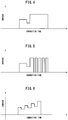
- FIG. 8B is an example of the changes in pulse when the weld current draws any curve.
- the shape of the pulses is not limited to a rectangle.
- the rising part and the trailing part may also be slanted with respect to time. That is, they may be trapezoidal or in extreme cases may be triangular.
- a "pulsation step” means a group of current pulses where the relationship between the conduction time and conduction idle time and the weld current can be expressed uniformly in a consecutive plurality of current pulses. For example, when a plurality of consecutive pulses are constant in conduction time ta and idle time ti and the weld current of a pulse becomes a function of time, the group of current pulses which can be expressed by that function becomes a single pulsation step.
- FIG. 8C shows an example of the pulsation step where the conduction time ta and idle time ti are constant and the weld current of a pulse becomes a linear function of time.
- FIG. 8D shows an example of the pulsation step where the conduction time ta and idle time ti are constant and the weld current of a pulse becomes a quadratic function of time. That is, if the relationship between the pulses can be uniformly expressed, the group of pulses can be referred to as a "pulsation step".
- FIG. 8E is an explanatory view schematically showing a conduction pattern discovered by the inventors suitable for when welding general hot stamped steel sheet and surface-treated hot stamped steel sheet by resistance spot welding.
- This resistance spot welding method has a plurality of pulsation steps. It is provided with an initial step of a first pulsation step and a succeeding second pulsation step.
- the minimum weld current in the second pulsation step is higher than the maximum weld current in the first pulsation step.
- the "maximum weld current in the first pulsation step” means the maximum value of the weld current of the pulses in the first pulsation step.
- the "minimum weld current in the second pulsation step” means the minimum value of the weld current of the pulses in the second pulsation step.
- the conduction time, idle time, and number of pulses can be adjusted by the type of the material, sheet thickness, and combination of sheets.
- the first pulsation step can be used to make use of the cooling efficiency of the electrodes while improving the fit of the contact surfaces of the steel sheets in a short time and to expand the press bonded part.
- the oxide layer at the steel sheet surface is locally broken and the part where the oxide layer is broken remarkably rises in current density whereby rapid melting rises and spatter easily occurs. Due to the first pulsation step where conduction and idling are repeated, the contact surfaces can be made to vibrate by heat expansion and contraction, so the high melting point oxide layer can be effectively broken.
- the conduction time per pulse in the first pulsation step is preferably 5 to 60 msec. If the conduction time is less than 5 msec, the heating time is short and the heat generation not sufficient, while if over 60 msec, the heating time is too long and the rate of occurrence of outer spatter and inner spatter is liable to rise.
- the conduction time is more preferably 15 msec or more. Further, the conduction time is more preferably 45 msec or less, still more preferably 25 msec or less.
- the weld current in the first pulsation step is preferably 5.0 to 14.0 kA. Normally, if the conduction time in pulsation increases, the upper limit current falls.
- the weld current is preferably suitably adjusted so that spatter does not occur in the first pulsation step in the range of 5.0 to 14.0 kA from the balance with the conduction time.
- the weld current is preferably set to a range of I 1 -3.0 to I 1 -0.2kA when making the upper limit current in the first pulsation step I 1 (kA). Further, to simplify the setting of the current control apparatus of the spot welding machine, it is preferable to set the weld current in the first pulsation step at a constant value.
- the conduction idle time in the first pulsation step (below, also referred to as the "idle time") is preferably 5 to 60 msec. If the idle time is less than 5 msec, the idling becomes short and cooling insufficient so inner spatter and outer spatter are liable to occur. On the other hand, if the idle time is over 60 msec, the cooling efficiency becomes too great and the nugget shape in the later explained second pulsation step is liable to become insufficient.
- the idle time is more preferably 15 msec or more. Further, the idle time is still more preferably 45 msec or less, even more preferably 25 msec or less.
- the current waveform at the first pulsation step is preferably a rectangular wave shape with a constant conduction time and idle time, but may also be a waveform including an up slope (rising part slanting to increase with respect to time) or down slope (trailing part slanting to decrease with respect to time).
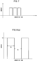
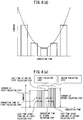
- the conduction system at the first pulsation step of the present invention is shown in FIG. 9.
- FIG. 9A shows a rectangular wave shape
- FIG. 9B shows an up slope waveform
- FIG. 9C shows a waveform including the rectangular shape after the up slope.
- FIG. 9D shows the down slope waveform after a rectangular wave shape
- FIG. 9E shows a waveform including both an up slope and down slope
- FIG. 9F shows a waveform becoming an up slope only at the first conduction.
- the number of pulses of the first pulsation step is preferably made at least two or more. This is because, in the case of surface-treated hot stamped steel sheet, if not performing the pulsation two times or more, sometimes the effect of suppressing spatter cannot be obtained.
- the number of pulses is more preferably three or more. In general, the larger the total sheet thickness, the more the number of pulses should be increased, but the number of pulses is preferably 50 or less.
- the present invention When applying the present invention to surface-treated hot stamped steel sheet treated on its surface by zinc oxide, as the first pulsation step, for example, it is preferable to repeat conduction and idling of 5.5 to 12kA at 8.3 to 20 msec (0.5 to 1 cycle at 50Hz or 60Hz) three to 25 times.
- the resistance spot welding method of the present invention is provided with a second pulsation step after the first pulsation step. It is possible to perform the first pulsation step to expand the conduction path (corona bond) and, after that, perform the second pulsation step to enlarge the nugget size.
- the second pulsation step makes the current a pulsation form (pulse shape) and thereby gently promotes the heat generation of the steel sheet.
- the minimum weld current in the second pulsation step is increased higher than the maximum weld current in the first pulsation step.
- the minimum weld current at the second pulsation step is preferably higher than the maximum weld current at the first pulsation step by 0.5 kA or more.
- the conduction time per pulse in the second pulsation step is preferably 5 to 60 msec. If the conduction time is less than 5 msec, the heating time becomes short and the heat generation is not sufficient, while if over 60 msec, the heating time is too long and the rate of occurrence of outer spatter and inner spatter is liable to rise.
- the conduction time is more preferably 15 msec or more. Further, the conduction time is more preferably 45 msec or less, still more preferably 25 msec or less .
- the weld current in the second pulsation step is preferably 5.0 to 16.0 kA. Normally, if the conduction time in a pulsation increases, the upper limit current falls.
- the weld current is preferably suitably adjusted so that spatter does not occur in the range of 5.0 to 16.0 kA from the balance with the conduction time.
- the weld current is preferably set to a range of I 2 -0.3 kA or less when making the upper limit current in the second pulsation step I 2 (kA). Further, to simplify the setting of the current control apparatus of the spot welding machine, it is preferable to set the weld current in the first pulsation step at a constant value.
- the conduction idle time in the second pulsation step is preferably 5 to 60 msec except at the end. If the idle time is less than 5 msec, the idling becomes short and cooling is insufficient so inner spatter and outer spatter are liable to occur. On the other hand, if the idle time is over 60 msec, the cooling efficiency becomes too great and expansion of the nugget size is liable to become difficult.
- the idle time is preferably 45 msec or more, more preferably 25 msec or less.
- the conduction idle time between the first pulsation step and the second pulsation step is preferably 5 to 120 msec. If this idle time is less than 5 msec, a large heat generation occurs at the time of the second pulsation step. Spatter occurs even with a low current value. On the other hand, if this idle time is over 120 msec, the nugget is cooled, the lower limit current for obtaining the target nugget size rises in the second pulsation step, and, as a result, the suitable current range becomes narrower.
- the idle time between the steps is preferably 10 msec or more, more preferably 15 msec or more. Further, the idle time between these steps is preferably 60 msec or less, more preferably 50 msec or less. Note that, when there is a pulsation step following the second pulsation step, the idle time between the second and third pulsation steps is not particularly limited.
- the number of pulses in the second pulsation step is at least three times or more. This is because if three times or less, sometimes the effect of enlargement of the nugget size cannot sufficiently be explained. More preferably, it is six times or more. In general, the larger the total sheet thickness, the more the number of pulses should be increased, but even if causing pulsation over 50 times, the effect tends to be saturated, so the number of pulses is preferably 50 times or less.
- the second pulsation step it is also possible to perform a further consecutive conduction or pulsation after the second pulsation step.
- the solidification segregation of phosphorus in the nugget is eased and the nugget is made a tempered martensite structure, so the merits are obtained that the toughness of the nugget is improved and the strength of the spot welded joint can be improved.
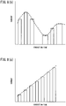
- FIG. 10A uses an up slope in the second pulsation
- FIG. 10B uses a rectangular wave shape after the up slope
- FIG. 10C is a waveform including a down slope after the rectangular wave shape and the up slope and down slope of FIG. 10D
- FIG. 10E is a waveform of an up slope only at the start of the second pulsation.
- FIG. 10F is a view showing a pattern of further pulsation conduction after the second pulsation.
- the resistance spot welding method according to the present invention may be further provided with a holding step of not running current, but using the electrodes to press against the steel sheets after the first pulsation step and second pulsation step.
- a holding step By providing the holding step, it is possible to reduce solidification cracking in the nugget.
- the holding time when providing a holding step is not particularly limited, but if the holding time is too long, it leads to an increase in the tact time, so 300 msec or less is preferable.
- an air pressure type inverter DC spot welding machine provided with a DR type electrode (aluminum dispersed copper) with a tip diameter of 6 mm and a tip R40 mm, two thickness 1.0 mm 1500 MPa class furnace heated ZnO-coated Al-plated hot stamped steel sheets were superposed and welded by resistance spot welding.
- the shape of the test piece on which the resistance spot welding is performed was made a strip of a width of 30 mm and length of 100 mm. Note that, the ZnO-coated Al-plated hot stamped steel sheet used in the present embodiment was fabricated by the following method.
- the Sendzimir method was used for Al plating.
- the annealing temperature at this time was about 800°C.
- the Al-plating bath contained Si: 9% and also contained Fe eluted from the steel strip.
- the amount of plating deposition was adjusted by the gas wiping method to adjust it to a single-sided 40 g/m 2 .
- water was sprayed at the time of cooling after plating. After cooling the Al plated steel sheet, a treatment solution was coated by a roll coater and the sheet was baked at about 80°C.
- the treatment solution was comprised of Nanotek Slurry made by C.I.
- the current value in the second pulsation step was changed and the nugget size and state of occurrence of spatter were investigated.
- the weld currents in the first pulsation step and the second pulsation step were respectively made constant values.
- the suitable current ranges of the second pulsation step at the different test numbers are shown in Table 2.
- the invention examples enable the upper limit currents to be raised in the second pulsation step even when superposing ZnO-coated Al-plated hot stamped steel sheets.
- an air pressure type inverter DC spot welding machine provided with a DR type electrode (aluminum dispersed copper) with a tip diameter of 6 mm and a tip R40 mm, thickness 0.7 mm 270 MPa class GA plated steel sheet, thickness 1.0 mm 1500 MPa class furnace heated ZnO-coated Al-plated hot stamped steel sheet, and thickness 1.2 mm 440 MPa class nonplated steel sheet were superposed and welded by resistance spot welding.
- the shape of the test piece in resistance spot welding was made a strip shape of a width of 30 mm and a length of 100 mm.
- the ZnO film-coated Al-plated hot stamped steel sheet was fabricated by the same method as in Example 1. The welding method is shown in Table 2. Note that, the pressing force was made a constant value (350 kgf) in the first pulsation step and second pulsation step.
- Example 2 In the same way as Example 1, after performing the first pulsation step at the current value shown in Table 1, the current value at the second pulsation step was changed to investigate the nugget size and the state of occurrence of spatter.
- the weld currents at the first pulsation step and second pulsation step were respectively made constant values.
- the suitable current ranges in the second pulsation steps in the test numbers are shown in Table 3.
- the invention examples can raise the upper limit current at the second pulsation step, so it is possible to obtain a broader suitable current range compared with the comparative examples having no pulsation step and performing single stage conduction.
- the present invention enables a broad suitable current range over 2.0 kA at the test piece level even with a combination of sheets envisioning resistance spot welding of three superposed sheets around a door opening such as roof rails, B-pillars, side seals, etc. of a car. Due to this, in the present invention, by setting the current value of the second pulsation step to a value of the 4 ⁇ t current +1.5kA to the spatter current, spatter will not occur even when welding actual parts and even if there is disturbance due to shunting and wear of electrodes, it is possible to stably secure a spot welded part with a nugget size of 4 ⁇ t or more. On the other hand, in the comparative examples, if setting the current to 4 ⁇ tcurrent +1.5kA, spatter is caused.
- a servo pressing type inverter DC spot welding machine provided with a DR type electrode (chrome copper) with a tip diameter of 6 mm and a tip R40 mm, two thickness 1.6 mm 1500 MPa class GA-plated hot stamped steel sheets (amount of plating deposition before hot stamping: 55 g/m 2 per side, heating conditions: 900°C, 4 minutes, furnace heating) were superposed and welded by resistance spot welding.
- the welding method is shown in Table 3.
- the shape of the test piece in the resistance spot welding is made a strip of a width of 30 mm and a length of 100 mm.
- the pressing force is a constant value (350 kgf) in the first pulsation step and second pulsation step.
- Example 2 the inventors performed the first pulsation step at the current value shown in Table 1, then changed the current value in the second pulsation step and investigated the nugget size and state of occurrence of spatter.
- the weld currents in the first pulsation step and second pulsation step are respectively made constant values.
- the suitable current ranges of the second pulsation step at the different test numbers are shown in Table 4.
- the invention examples enable the upper limit current in the second pulsation step to be raised, so it is possible to obtain a broad 1.5 kA or more suitable current range at the test piece level even compared with the comparative examples which have no pulsation step and perform a single stage of conduction. Due to this, in the present invention, by setting the current value of the second pulsation step to 4 ⁇ tcurrent +1.5kA to the spatter current, spatter will not occur even when welding actual parts and even if there is disturbance due to shunting and wear of electrodes, it is possible to stably secure a spot welded part with a nugget size of 4 ⁇ t or more.
- the present invention in resistance spot welding of superposed high tensile steel sheets, it is possible to suppress the occurrence of both outer spatter and inner spatter while enlarging the nugget size in resistance spot welding even if using an inverter DC power supply. Therefore, if using the resistance spot welding method according to the present invention, it becomes possible to efficiently and stably perform resistance spot welding even with steel sheet where spatter easily occurs such as surface-treated hot stamped steel sheet.
- the resistance spot welding method it is possible to improve the quality of appearance of a the side panels and other parts of a car body by suppressing the occurrence of spatter. Further, it is possible to prevent spatter from sticking to the moving parts of the robot and therefore improve the operating rate of the robot. Further, it is possible to eliminate later processes accompanying the occurrence of spatter such as deburring, so it is possible to improve the work efficiency.
Landscapes
- Engineering & Computer Science (AREA)
- Mechanical Engineering (AREA)
- Resistance Welding (AREA)
Applications Claiming Priority (2)
| Application Number | Priority Date | Filing Date | Title |
|---|---|---|---|
| JP2013263272 | 2013-12-20 | ||
| PCT/JP2014/083571 WO2015093568A1 (ja) | 2013-12-20 | 2014-12-18 | 抵抗スポット溶接方法 |
Publications (3)
| Publication Number | Publication Date |
|---|---|
| EP3085485A1 EP3085485A1 (en) | 2016-10-26 |
| EP3085485A4 EP3085485A4 (en) | 2017-08-23 |
| EP3085485B1 true EP3085485B1 (en) | 2019-10-23 |
Family
ID=53402910
Family Applications (1)
| Application Number | Title | Priority Date | Filing Date |
|---|---|---|---|
| EP14870854.8A Not-in-force EP3085485B1 (en) | 2013-12-20 | 2014-12-18 | Resistance spot welding method |
Country Status (10)
| Country | Link |
|---|---|
| US (1) | US10406627B2 (ko) |
| EP (1) | EP3085485B1 (ko) |
| JP (1) | JP6137337B2 (ko) |
| KR (1) | KR101887789B1 (ko) |
| CN (1) | CN105636735B (ko) |
| CA (1) | CA2926914A1 (ko) |
| ES (1) | ES2764835T3 (ko) |
| MX (1) | MX2016006347A (ko) |
| RU (1) | RU2663659C2 (ko) |
| WO (1) | WO2015093568A1 (ko) |
Cited By (1)
| Publication number | Priority date | Publication date | Assignee | Title |
|---|---|---|---|---|
| DE102022104981A1 (de) | 2022-03-03 | 2023-09-07 | Thyssenkrupp Steel Europe Ag | Verfahren zum Widerstandspunktschweißen von gehärteten Stahlblechbauteilen |
Families Citing this family (25)
| Publication number | Priority date | Publication date | Assignee | Title |
|---|---|---|---|---|
| JP6493093B2 (ja) * | 2015-08-27 | 2019-04-03 | 新日鐵住金株式会社 | 抵抗スポット溶接用電源装置 |
| US10272515B2 (en) * | 2015-09-15 | 2019-04-30 | GM Global Technology Operations LLC | Power pulse method for controlling resistance weld nugget growth and properties during steel spot welding |
| CN108015401B (zh) * | 2016-11-04 | 2020-06-23 | 宝山钢铁股份有限公司 | 具有良好接头性能的镀锌高强钢电阻点焊方法 |
| CN110461527A (zh) * | 2017-03-30 | 2019-11-15 | 日本制铁株式会社 | 焊接接头的制造方法及焊接接头 |
| CN106994551A (zh) * | 2017-05-17 | 2017-08-01 | 中南大学 | 一种能有效提高先进高强钢钢板焊点强度的电阻点焊工艺 |
| JP6913062B2 (ja) * | 2017-08-18 | 2021-08-04 | Jfeスチール株式会社 | 抵抗スポット溶接方法および溶接部材の製造方法 |
| JP6945929B2 (ja) * | 2017-09-28 | 2021-10-06 | ダイハツ工業株式会社 | スポット溶接方法及び鋼板部品の製造方法 |
| WO2019124467A1 (ja) | 2017-12-19 | 2019-06-27 | 日本製鉄株式会社 | 抵抗スポット溶接継手の製造方法 |
| WO2019180923A1 (ja) * | 2018-03-23 | 2019-09-26 | 本田技研工業株式会社 | スポット溶接方法 |
| JP6963282B2 (ja) * | 2018-04-20 | 2021-11-05 | 株式会社神戸製鋼所 | アルミニウム材の抵抗スポット溶接継手、及びアルミニウム材の抵抗スポット溶接方法 |
| WO2020045678A1 (ja) * | 2018-08-31 | 2020-03-05 | 豊田鉄工株式会社 | 抵抗スポット溶接方法 |
| CN112533725A (zh) * | 2018-09-13 | 2021-03-19 | 安赛乐米塔尔公司 | 至少两个金属基底的组件 |
| MX2021002859A (es) * | 2018-09-13 | 2021-05-28 | Arcelormittal | Un metodo de soldadura para la fabricacion de un montaje de al menos 2 sustratos metalicos. |
| KR102456479B1 (ko) * | 2018-09-13 | 2022-10-18 | 아르셀러미탈 | 적어도 2개의 금속성 기재들의 조립체 |
| JP7364849B2 (ja) * | 2019-03-28 | 2023-10-19 | 日本製鉄株式会社 | スポット溶接継手の製造方法及びスポット溶接機 |
| US20220288718A1 (en) * | 2019-08-20 | 2022-09-15 | Honda Motor Co., Ltd. | Spot welding method |
| JP7240672B2 (ja) * | 2019-10-18 | 2023-03-16 | 株式会社神戸製鋼所 | アルミニウム材の抵抗スポット溶接方法、アルミニウム材の抵抗スポット溶接制御装置、および抵抗スポット溶接機 |
| KR102370405B1 (ko) * | 2020-02-07 | 2022-03-04 | 서울대학교산학협력단 | 고엔트로피 합금의 접합 방법, 고엔트로피 합금의 접합 장치 및 고엔트로피 합금의 접합 구조체 |
| KR20230148379A (ko) | 2021-04-12 | 2023-10-24 | 제이에프이 스틸 가부시키가이샤 | 저항 스폿 용접 방법 |
| CN113441826A (zh) * | 2021-07-16 | 2021-09-28 | 上海交通大学 | 抑制镀锌高强钢电阻点焊接头液态金属脆裂纹的点焊工艺 |
| CN114101883B (zh) * | 2021-11-26 | 2023-06-02 | 中国科学院上海光学精密机械研究所 | 一种用于低熔点涂镀层钢工件的电阻点焊方法 |
| CN114192953A (zh) * | 2021-12-20 | 2022-03-18 | 南昌江铃集团协和传动技术有限公司 | 二次脉冲焊接镀锌板工艺 |
| CN115106633A (zh) * | 2022-06-27 | 2022-09-27 | 河钢股份有限公司 | 一种用于热镀锌热成形钢的电阻点焊方法 |
| WO2024006657A1 (en) * | 2022-06-30 | 2024-01-04 | Novelis Inc. | Systems and methods for improving resistance spot welding with cast aluminum |
| CN115446437B (zh) * | 2022-09-14 | 2023-11-10 | 首钢集团有限公司 | 一种电阻点焊方法、装置、设备及存储介质 |
Family Cites Families (21)
| Publication number | Priority date | Publication date | Assignee | Title |
|---|---|---|---|---|
| US3233116A (en) * | 1961-11-28 | 1966-02-01 | Gen Electric | Control rectifiers having timing means energized in response to load effecting commutation |
| SU1197796A1 (ru) | 1984-05-08 | 1985-12-15 | Центральный Научно-Исследовательский И Проектно-Конструкторский Институт Механизации И Энергетики Лесной Промышленности | Способ заточки пил |
| CH686617A5 (de) * | 1992-03-09 | 1996-05-15 | Max Breitmeier | Elektrische Speiseschaltung zur Erzeugung von einzeln steuerbaren Stromimpulsen. |
| JP3236662B2 (ja) * | 1992-04-21 | 2001-12-10 | 亮拿 佐藤 | スポット溶接装置 |
| JP2003236674A (ja) | 2002-02-15 | 2003-08-26 | Mazda Motor Corp | 高張力鋼板のスポット溶接方法およびその装置 |
| RU2243071C2 (ru) * | 2002-07-01 | 2004-12-27 | Открытое акционерное общество "АВТОВАЗ" | Способ контактной точечной сварки оцинкованных стальных листов |
| JP4753411B2 (ja) | 2004-12-28 | 2011-08-24 | ダイハツ工業株式会社 | スポット抵抗溶接の通電制御方法 |
| JP4728926B2 (ja) | 2006-10-16 | 2011-07-20 | 新日本製鐵株式会社 | 重ね抵抗スポット溶接方法 |
| US8835795B2 (en) * | 2008-11-14 | 2014-09-16 | Toyota Motor Engineering & Manufacturing North America, Inc. | Method for implementing spatter-less welding |
| JP5359571B2 (ja) | 2009-02-12 | 2013-12-04 | 新日鐵住金株式会社 | 高張力鋼板の抵抗溶接方法および抵抗溶接継手の製造方法 |
| JP2010188408A (ja) | 2009-02-20 | 2010-09-02 | Honda Motor Co Ltd | 抵抗溶接の通電方法 |
| JP5332857B2 (ja) * | 2009-04-20 | 2013-11-06 | 新日鐵住金株式会社 | 高張力鋼板の抵抗溶接方法 |
| CN102596481B (zh) * | 2009-07-31 | 2015-04-15 | 高周波热炼株式会社 | 焊接构造构件及焊接方法 |
| US8278598B2 (en) * | 2009-08-14 | 2012-10-02 | Arcelormittal Investigacion Y Desarrollo, S.L. | Methods and systems for resistance spot welding using direct current micro pulses |
| KR101593642B1 (ko) * | 2010-06-29 | 2016-02-16 | 한양대학교 산학협력단 | 인버터 직류 저항 점 용접 시스템, 그의 용접 공정 제어방법 및 그의 퍼지 제어기 설계방법 |
| JP5653116B2 (ja) * | 2010-08-03 | 2015-01-14 | 株式会社ダイヘン | メッキ鋼板の抵抗溶接制御方法 |
| JP5063757B2 (ja) * | 2010-08-17 | 2012-10-31 | 本田技研工業株式会社 | 車体側部構造 |
| JP5770523B2 (ja) * | 2011-04-28 | 2015-08-26 | 三栄商事株式会社 | せん断補強筋のスポット溶接方法 |
| CN103687780A (zh) * | 2011-07-12 | 2014-03-26 | 本田技研工业株式会社 | 车辆的侧外面板 |
| UA112663C2 (uk) * | 2011-09-30 | 2016-10-10 | Арселормітталь Інвестігасіон І Десаррольо, С.Л. | Легкі сталеві двері для транспортного засобу і спосіб для їх виготовлення |
| US9737956B2 (en) * | 2013-06-14 | 2017-08-22 | GM Global Technology Operations LLC | Resistance spot welding thin gauge steels |
-
2014
- 2014-12-18 JP JP2015553603A patent/JP6137337B2/ja active Active
- 2014-12-18 WO PCT/JP2014/083571 patent/WO2015093568A1/ja active Application Filing
- 2014-12-18 CA CA2926914A patent/CA2926914A1/en not_active Abandoned
- 2014-12-18 ES ES14870854T patent/ES2764835T3/es active Active
- 2014-12-18 RU RU2016124112A patent/RU2663659C2/ru not_active IP Right Cessation
- 2014-12-18 MX MX2016006347A patent/MX2016006347A/es unknown
- 2014-12-18 US US15/025,459 patent/US10406627B2/en not_active Expired - Fee Related
- 2014-12-18 CN CN201480056857.3A patent/CN105636735B/zh not_active Expired - Fee Related
- 2014-12-18 KR KR1020167007798A patent/KR101887789B1/ko active IP Right Grant
- 2014-12-18 EP EP14870854.8A patent/EP3085485B1/en not_active Not-in-force
Non-Patent Citations (1)
| Title |
|---|
| None * |
Cited By (1)
| Publication number | Priority date | Publication date | Assignee | Title |
|---|---|---|---|---|
| DE102022104981A1 (de) | 2022-03-03 | 2023-09-07 | Thyssenkrupp Steel Europe Ag | Verfahren zum Widerstandspunktschweißen von gehärteten Stahlblechbauteilen |
Also Published As
| Publication number | Publication date |
|---|---|
| US20160228973A1 (en) | 2016-08-11 |
| MX2016006347A (es) | 2016-08-01 |
| CN105636735B (zh) | 2019-05-07 |
| KR20160045892A (ko) | 2016-04-27 |
| ES2764835T3 (es) | 2020-06-04 |
| EP3085485A1 (en) | 2016-10-26 |
| EP3085485A4 (en) | 2017-08-23 |
| JPWO2015093568A1 (ja) | 2017-03-23 |
| KR101887789B1 (ko) | 2018-08-10 |
| JP6137337B2 (ja) | 2017-05-31 |
| WO2015093568A1 (ja) | 2015-06-25 |
| US10406627B2 (en) | 2019-09-10 |
| RU2016124112A (ru) | 2018-01-25 |
| RU2663659C2 (ru) | 2018-08-08 |
| CN105636735A (zh) | 2016-06-01 |
| CA2926914A1 (en) | 2015-06-25 |
Similar Documents
| Publication | Publication Date | Title |
|---|---|---|
| EP3085485B1 (en) | Resistance spot welding method | |
| JP6094676B2 (ja) | 抵抗スポット溶接方法 | |
| JP7383718B2 (ja) | アルミニウム又はアルミニウム合金メッキ層付きの鋼製薄肉溶接等強度部品の製造方法 | |
| US9157138B2 (en) | Complex metallographic structured high strength steel and method of manufacturing | |
| CN107350613B (zh) | 带有涂镀层的钢工件的电阻点焊工艺方法 | |
| CN108025387B (zh) | 点焊方法 | |
| CA3056594A1 (en) | Multiphase, cold-rolled ultra-high strength steel | |
| WO2022097736A1 (ja) | 亜鉛めっき鋼板,電着塗装鋼板,自動車部品,電着塗装鋼板の製造方法,及び亜鉛めっき鋼板の製造方法 | |
| US20210323083A1 (en) | A welding method for the manufacture of an assembly of at least 2 metallic substrates | |
| JP5741364B2 (ja) | 接着強度に優れた合金化溶融亜鉛めっき鋼板とその製造方法 | |
| JP3843042B2 (ja) | 抵抗溶接性に優れたアルミニウムめっき鋼板とこれを用いた加工部品 | |
| JP3849525B2 (ja) | 高張力亜鉛系めっき鋼板のスポット溶接方法 | |
| JP7522977B2 (ja) | 抵抗スポット溶接方法 | |
| JPH04371371A (ja) | 抵抗スポット溶接方法 |
Legal Events
| Date | Code | Title | Description |
|---|---|---|---|
| PUAI | Public reference made under article 153(3) epc to a published international application that has entered the european phase |
Free format text: ORIGINAL CODE: 0009012 |
|
| 17P | Request for examination filed |
Effective date: 20160331 |
|
| AK | Designated contracting states |
Kind code of ref document: A1 Designated state(s): AL AT BE BG CH CY CZ DE DK EE ES FI FR GB GR HR HU IE IS IT LI LT LU LV MC MK MT NL NO PL PT RO RS SE SI SK SM TR |
|
| AX | Request for extension of the european patent |
Extension state: BA ME |
|
| DAX | Request for extension of the european patent (deleted) | ||
| A4 | Supplementary search report drawn up and despatched |
Effective date: 20170726 |
|
| RIC1 | Information provided on ipc code assigned before grant |
Ipc: B23K 11/16 20060101ALI20170720BHEP Ipc: B23K 11/24 20060101ALI20170720BHEP Ipc: B23K 11/11 20060101AFI20170720BHEP |
|
| STAA | Information on the status of an ep patent application or granted ep patent |
Free format text: STATUS: EXAMINATION IS IN PROGRESS |
|
| 17Q | First examination report despatched |
Effective date: 20180517 |
|
| GRAP | Despatch of communication of intention to grant a patent |
Free format text: ORIGINAL CODE: EPIDOSNIGR1 |
|
| STAA | Information on the status of an ep patent application or granted ep patent |
Free format text: STATUS: GRANT OF PATENT IS INTENDED |
|
| INTG | Intention to grant announced |
Effective date: 20190430 |
|
| RAP1 | Party data changed (applicant data changed or rights of an application transferred) |
Owner name: NIPPON STEEL CORPORATION |
|
| GRAS | Grant fee paid |
Free format text: ORIGINAL CODE: EPIDOSNIGR3 |
|
| GRAA | (expected) grant |
Free format text: ORIGINAL CODE: 0009210 |
|
| STAA | Information on the status of an ep patent application or granted ep patent |
Free format text: STATUS: THE PATENT HAS BEEN GRANTED |
|
| AK | Designated contracting states |
Kind code of ref document: B1 Designated state(s): AL AT BE BG CH CY CZ DE DK EE ES FI FR GB GR HR HU IE IS IT LI LT LU LV MC MK MT NL NO PL PT RO RS SE SI SK SM TR |
|
| REG | Reference to a national code |
Ref country code: GB Ref legal event code: FG4D |
|
| REG | Reference to a national code |
Ref country code: CH Ref legal event code: EP |
|
| REG | Reference to a national code |
Ref country code: IE Ref legal event code: FG4D |
|
| REG | Reference to a national code |
Ref country code: DE Ref legal event code: R096 Ref document number: 602014055746 Country of ref document: DE |
|
| REG | Reference to a national code |
Ref country code: AT Ref legal event code: REF Ref document number: 1193134 Country of ref document: AT Kind code of ref document: T Effective date: 20191115 |
|
| REG | Reference to a national code |
Ref country code: NL Ref legal event code: MP Effective date: 20191023 |
|
| REG | Reference to a national code |
Ref country code: LT Ref legal event code: MG4D |
|
| PGFP | Annual fee paid to national office [announced via postgrant information from national office to epo] |
Ref country code: TR Payment date: 20191118 Year of fee payment: 6 |
|
| PG25 | Lapsed in a contracting state [announced via postgrant information from national office to epo] |
Ref country code: BG Free format text: LAPSE BECAUSE OF FAILURE TO SUBMIT A TRANSLATION OF THE DESCRIPTION OR TO PAY THE FEE WITHIN THE PRESCRIBED TIME-LIMIT Effective date: 20200123 Ref country code: FI Free format text: LAPSE BECAUSE OF FAILURE TO SUBMIT A TRANSLATION OF THE DESCRIPTION OR TO PAY THE FEE WITHIN THE PRESCRIBED TIME-LIMIT Effective date: 20191023 Ref country code: PT Free format text: LAPSE BECAUSE OF FAILURE TO SUBMIT A TRANSLATION OF THE DESCRIPTION OR TO PAY THE FEE WITHIN THE PRESCRIBED TIME-LIMIT Effective date: 20200224 Ref country code: NL Free format text: LAPSE BECAUSE OF FAILURE TO SUBMIT A TRANSLATION OF THE DESCRIPTION OR TO PAY THE FEE WITHIN THE PRESCRIBED TIME-LIMIT Effective date: 20191023 Ref country code: LV Free format text: LAPSE BECAUSE OF FAILURE TO SUBMIT A TRANSLATION OF THE DESCRIPTION OR TO PAY THE FEE WITHIN THE PRESCRIBED TIME-LIMIT Effective date: 20191023 Ref country code: SE Free format text: LAPSE BECAUSE OF FAILURE TO SUBMIT A TRANSLATION OF THE DESCRIPTION OR TO PAY THE FEE WITHIN THE PRESCRIBED TIME-LIMIT Effective date: 20191023 Ref country code: PL Free format text: LAPSE BECAUSE OF FAILURE TO SUBMIT A TRANSLATION OF THE DESCRIPTION OR TO PAY THE FEE WITHIN THE PRESCRIBED TIME-LIMIT Effective date: 20191023 Ref country code: NO Free format text: LAPSE BECAUSE OF FAILURE TO SUBMIT A TRANSLATION OF THE DESCRIPTION OR TO PAY THE FEE WITHIN THE PRESCRIBED TIME-LIMIT Effective date: 20200123 Ref country code: GR Free format text: LAPSE BECAUSE OF FAILURE TO SUBMIT A TRANSLATION OF THE DESCRIPTION OR TO PAY THE FEE WITHIN THE PRESCRIBED TIME-LIMIT Effective date: 20200124 Ref country code: LT Free format text: LAPSE BECAUSE OF FAILURE TO SUBMIT A TRANSLATION OF THE DESCRIPTION OR TO PAY THE FEE WITHIN THE PRESCRIBED TIME-LIMIT Effective date: 20191023 |
|
| PGFP | Annual fee paid to national office [announced via postgrant information from national office to epo] |
Ref country code: ES Payment date: 20200109 Year of fee payment: 6 |
|
| PG25 | Lapsed in a contracting state [announced via postgrant information from national office to epo] |
Ref country code: HR Free format text: LAPSE BECAUSE OF FAILURE TO SUBMIT A TRANSLATION OF THE DESCRIPTION OR TO PAY THE FEE WITHIN THE PRESCRIBED TIME-LIMIT Effective date: 20191023 Ref country code: IS Free format text: LAPSE BECAUSE OF FAILURE TO SUBMIT A TRANSLATION OF THE DESCRIPTION OR TO PAY THE FEE WITHIN THE PRESCRIBED TIME-LIMIT Effective date: 20200224 Ref country code: RS Free format text: LAPSE BECAUSE OF FAILURE TO SUBMIT A TRANSLATION OF THE DESCRIPTION OR TO PAY THE FEE WITHIN THE PRESCRIBED TIME-LIMIT Effective date: 20191023 |
|
| REG | Reference to a national code |
Ref country code: ES Ref legal event code: FG2A Ref document number: 2764835 Country of ref document: ES Kind code of ref document: T3 Effective date: 20200604 |
|
| PG25 | Lapsed in a contracting state [announced via postgrant information from national office to epo] |
Ref country code: AL Free format text: LAPSE BECAUSE OF FAILURE TO SUBMIT A TRANSLATION OF THE DESCRIPTION OR TO PAY THE FEE WITHIN THE PRESCRIBED TIME-LIMIT Effective date: 20191023 |
|
| REG | Reference to a national code |
Ref country code: DE Ref legal event code: R097 Ref document number: 602014055746 Country of ref document: DE |
|
| PG2D | Information on lapse in contracting state deleted |
Ref country code: IS |
|
| PG25 | Lapsed in a contracting state [announced via postgrant information from national office to epo] |
Ref country code: DK Free format text: LAPSE BECAUSE OF FAILURE TO SUBMIT A TRANSLATION OF THE DESCRIPTION OR TO PAY THE FEE WITHIN THE PRESCRIBED TIME-LIMIT Effective date: 20191023 Ref country code: EE Free format text: LAPSE BECAUSE OF FAILURE TO SUBMIT A TRANSLATION OF THE DESCRIPTION OR TO PAY THE FEE WITHIN THE PRESCRIBED TIME-LIMIT Effective date: 20191023 Ref country code: RO Free format text: LAPSE BECAUSE OF FAILURE TO SUBMIT A TRANSLATION OF THE DESCRIPTION OR TO PAY THE FEE WITHIN THE PRESCRIBED TIME-LIMIT Effective date: 20191023 Ref country code: CZ Free format text: LAPSE BECAUSE OF FAILURE TO SUBMIT A TRANSLATION OF THE DESCRIPTION OR TO PAY THE FEE WITHIN THE PRESCRIBED TIME-LIMIT Effective date: 20191023 Ref country code: IS Free format text: LAPSE BECAUSE OF FAILURE TO SUBMIT A TRANSLATION OF THE DESCRIPTION OR TO PAY THE FEE WITHIN THE PRESCRIBED TIME-LIMIT Effective date: 20200223 |
|
| REG | Reference to a national code |
Ref country code: CH Ref legal event code: PL |
|
| REG | Reference to a national code |
Ref country code: AT Ref legal event code: MK05 Ref document number: 1193134 Country of ref document: AT Kind code of ref document: T Effective date: 20191023 |
|
| REG | Reference to a national code |
Ref country code: BE Ref legal event code: MM Effective date: 20191231 |
|
| PLBE | No opposition filed within time limit |
Free format text: ORIGINAL CODE: 0009261 |
|
| STAA | Information on the status of an ep patent application or granted ep patent |
Free format text: STATUS: NO OPPOSITION FILED WITHIN TIME LIMIT |
|
| PG25 | Lapsed in a contracting state [announced via postgrant information from national office to epo] |
Ref country code: SM Free format text: LAPSE BECAUSE OF FAILURE TO SUBMIT A TRANSLATION OF THE DESCRIPTION OR TO PAY THE FEE WITHIN THE PRESCRIBED TIME-LIMIT Effective date: 20191023 Ref country code: IT Free format text: LAPSE BECAUSE OF FAILURE TO SUBMIT A TRANSLATION OF THE DESCRIPTION OR TO PAY THE FEE WITHIN THE PRESCRIBED TIME-LIMIT Effective date: 20191023 Ref country code: MC Free format text: LAPSE BECAUSE OF FAILURE TO SUBMIT A TRANSLATION OF THE DESCRIPTION OR TO PAY THE FEE WITHIN THE PRESCRIBED TIME-LIMIT Effective date: 20191023 Ref country code: SK Free format text: LAPSE BECAUSE OF FAILURE TO SUBMIT A TRANSLATION OF THE DESCRIPTION OR TO PAY THE FEE WITHIN THE PRESCRIBED TIME-LIMIT Effective date: 20191023 |
|
| GBPC | Gb: european patent ceased through non-payment of renewal fee |
Effective date: 20200123 |
|
| 26N | No opposition filed |
Effective date: 20200724 |
|
| PG25 | Lapsed in a contracting state [announced via postgrant information from national office to epo] |
Ref country code: GB Free format text: LAPSE BECAUSE OF NON-PAYMENT OF DUE FEES Effective date: 20200123 Ref country code: IE Free format text: LAPSE BECAUSE OF NON-PAYMENT OF DUE FEES Effective date: 20191218 Ref country code: LU Free format text: LAPSE BECAUSE OF NON-PAYMENT OF DUE FEES Effective date: 20191218 |
|
| PG25 | Lapsed in a contracting state [announced via postgrant information from national office to epo] |
Ref country code: BE Free format text: LAPSE BECAUSE OF NON-PAYMENT OF DUE FEES Effective date: 20191231 Ref country code: CH Free format text: LAPSE BECAUSE OF NON-PAYMENT OF DUE FEES Effective date: 20191231 Ref country code: AT Free format text: LAPSE BECAUSE OF FAILURE TO SUBMIT A TRANSLATION OF THE DESCRIPTION OR TO PAY THE FEE WITHIN THE PRESCRIBED TIME-LIMIT Effective date: 20191023 Ref country code: LI Free format text: LAPSE BECAUSE OF NON-PAYMENT OF DUE FEES Effective date: 20191231 Ref country code: SI Free format text: LAPSE BECAUSE OF FAILURE TO SUBMIT A TRANSLATION OF THE DESCRIPTION OR TO PAY THE FEE WITHIN THE PRESCRIBED TIME-LIMIT Effective date: 20191023 |
|
| PG25 | Lapsed in a contracting state [announced via postgrant information from national office to epo] |
Ref country code: CY Free format text: LAPSE BECAUSE OF FAILURE TO SUBMIT A TRANSLATION OF THE DESCRIPTION OR TO PAY THE FEE WITHIN THE PRESCRIBED TIME-LIMIT Effective date: 20191023 |
|
| PG25 | Lapsed in a contracting state [announced via postgrant information from national office to epo] |
Ref country code: HU Free format text: LAPSE BECAUSE OF FAILURE TO SUBMIT A TRANSLATION OF THE DESCRIPTION OR TO PAY THE FEE WITHIN THE PRESCRIBED TIME-LIMIT; INVALID AB INITIO Effective date: 20141218 Ref country code: MT Free format text: LAPSE BECAUSE OF FAILURE TO SUBMIT A TRANSLATION OF THE DESCRIPTION OR TO PAY THE FEE WITHIN THE PRESCRIBED TIME-LIMIT Effective date: 20191023 |
|
| PGFP | Annual fee paid to national office [announced via postgrant information from national office to epo] |
Ref country code: FR Payment date: 20211109 Year of fee payment: 8 Ref country code: DE Payment date: 20211102 Year of fee payment: 8 |
|
| REG | Reference to a national code |
Ref country code: ES Ref legal event code: FD2A Effective date: 20220221 |
|
| PG25 | Lapsed in a contracting state [announced via postgrant information from national office to epo] |
Ref country code: ES Free format text: LAPSE BECAUSE OF NON-PAYMENT OF DUE FEES Effective date: 20201219 |
|
| PG25 | Lapsed in a contracting state [announced via postgrant information from national office to epo] |
Ref country code: TR Free format text: LAPSE BECAUSE OF NON-PAYMENT OF DUE FEES Effective date: 20201218 Ref country code: MK Free format text: LAPSE BECAUSE OF FAILURE TO SUBMIT A TRANSLATION OF THE DESCRIPTION OR TO PAY THE FEE WITHIN THE PRESCRIBED TIME-LIMIT Effective date: 20191023 |
|
| REG | Reference to a national code |
Ref country code: DE Ref legal event code: R119 Ref document number: 602014055746 Country of ref document: DE |
|
| PG25 | Lapsed in a contracting state [announced via postgrant information from national office to epo] |
Ref country code: DE Free format text: LAPSE BECAUSE OF NON-PAYMENT OF DUE FEES Effective date: 20230701 |
|
| PG25 | Lapsed in a contracting state [announced via postgrant information from national office to epo] |
Ref country code: FR Free format text: LAPSE BECAUSE OF NON-PAYMENT OF DUE FEES Effective date: 20221231 |